EP3470831A1 - Chemical for test used in hazardous substance sensing device, hazardous substance sensing device, and hazardous substance sensing method - Google Patents
Chemical for test used in hazardous substance sensing device, hazardous substance sensing device, and hazardous substance sensing method Download PDFInfo
- Publication number
- EP3470831A1 EP3470831A1 EP17813002.7A EP17813002A EP3470831A1 EP 3470831 A1 EP3470831 A1 EP 3470831A1 EP 17813002 A EP17813002 A EP 17813002A EP 3470831 A1 EP3470831 A1 EP 3470831A1
- Authority
- EP
- European Patent Office
- Prior art keywords
- substance
- hazardous substance
- reagent
- hazardous
- sensing device
- Prior art date
- Legal status (The legal status is an assumption and is not a legal conclusion. Google has not performed a legal analysis and makes no representation as to the accuracy of the status listed.)
- Granted
Links
Images




Classifications
-
- G—PHYSICS
- G01—MEASURING; TESTING
- G01N—INVESTIGATING OR ANALYSING MATERIALS BY DETERMINING THEIR CHEMICAL OR PHYSICAL PROPERTIES
- G01N33/00—Investigating or analysing materials by specific methods not covered by groups G01N1/00 - G01N31/00
- G01N33/22—Fuels; Explosives
- G01N33/227—Explosives, e.g. combustive properties thereof
-
- H—ELECTRICITY
- H01—ELECTRIC ELEMENTS
- H01J—ELECTRIC DISCHARGE TUBES OR DISCHARGE LAMPS
- H01J49/00—Particle spectrometers or separator tubes
- H01J49/26—Mass spectrometers or separator tubes
- H01J49/34—Dynamic spectrometers
- H01J49/42—Stability-of-path spectrometers, e.g. monopole, quadrupole, multipole, farvitrons
- H01J49/4205—Device types
- H01J49/422—Two-dimensional RF ion traps
-
- H—ELECTRICITY
- H01—ELECTRIC ELEMENTS
- H01J—ELECTRIC DISCHARGE TUBES OR DISCHARGE LAMPS
- H01J49/00—Particle spectrometers or separator tubes
- H01J49/26—Mass spectrometers or separator tubes
- H01J49/34—Dynamic spectrometers
- H01J49/42—Stability-of-path spectrometers, e.g. monopole, quadrupole, multipole, farvitrons
- H01J49/4205—Device types
- H01J49/422—Two-dimensional RF ion traps
- H01J49/4225—Multipole linear ion traps, e.g. quadrupoles, hexapoles
-
- H—ELECTRICITY
- H01—ELECTRIC ELEMENTS
- H01J—ELECTRIC DISCHARGE TUBES OR DISCHARGE LAMPS
- H01J49/00—Particle spectrometers or separator tubes
- H01J49/26—Mass spectrometers or separator tubes
Definitions
- the present invention relates to a chemical for a test used in a hazardous substance sensing device, a hazardous substance sensing device, and a hazardous substance sensing method.
- a threat of terrorism is globally increased and countermeasures against terrorism due to a hazardous substance such as explosives are required for important facilities such as a nuclear power plant.
- terrorism and crime due to the explosives are a threat in daily life.
- a case such as arresting a suspect who tried suicide bombing inside the commuter train is reported.
- a device for sensing such hazardous substance there is known a device in which an inspection target is sampled, the inspection target is mass analyzed by applying a mass spectrometry technique, and the fact that the hazardous substance is detected is displayed on a display, when a substance corresponding to an ion of the hazardous substance is detected in a mass analysis result.
- the operation of the device is confirmed in many cases by inputting a reagent containing the same substance as a hazardous substance.
- the reagent containing the same substance as the hazardous substance is input, the same mass spectrum as the hazardous substance is measured.
- the hazardous substance reagent may remain in the device. There was a problem that it was impossible to distinguish between erroneous sensing due to the hazardous substance reagent remaining when the hazardous substance was sensed during operation and sensing of the hazardous substance due to a real hazardous substance.
- An object of the present invention is to provide a chemical for a test used in a hazardous substance sensing device, a hazardous substance sensing device, and a hazardous substance sensing method capable of suppressing malfunction even in a case where a reagent (reagent chemical) corresponding to a hazardous substance is used.
- a hazardous substance sensing device using a reagent chemical to which an indicator substance different from a hazardous substance as a detection target is added and calibrated based on the detection target included in the reagent chemical, the device including an analysis unit performing mass analysis, and a determination unit determining that the detection target is included, in a case where a peak corresponding to the indicator substance is not included and a peak corresponding to the substance as the detection target is included in a spectrum as an analysis result of the analysis unit.
- a chemical for a test of a hazardous substance sensing device including a hazardous substance as a detection target, and an additional substance as an indicator substance different from the hazardous substance.
- the trace type hazardous substance sensing device having a mass spectrometer used for the hazardous substance sensing
- a technique that can distinguish whether the hazardous substance reagent is a real hazardous substance or a remaining hazardous substance reagent is proposed.
- the trace type hazardous substance sensing device mainly determines the substance contained in an inspection substance from the obtained mass spectrum from the result of generating ions from the inspection substance and performing mass analysis. Therefore, the indicator substance is added to the hazardous substance reagent so that the mass spectrum which does not originally occur in a case where the hazardous substance is inspected is measured.
- a mass spectrum of a hazardous substance sensing and a mass spectrum of a reagent indicator substance sensing are set in the trace type hazardous substance sensing device, and even in a case where the mass spectrum of the hazardous substance sensing is sensed at the time of inspecting the hazardous substance, in a case where the mass spectrum of the reagent indicator substance sensing is sensed simultaneously, immediately before, or immediately after, a configuration of an alarm condition such as excluding from the alarm condition of the hazardous substance sensing is adopted. Therefore, a chemical for a test is excluded from an alarm and it is possible to prevent erroneous sensing due to the chemical for the test during operation. Therefore, even if the chemical for the test is mistakenly mixed in the operation of the trace type hazardous substance sensing device, it is possible to determine that it is the chemical for the test without determining it as the hazardous substance.
- FIG. 1 is a diagram illustrating an example of a configuration of a fine particle inspection device as a trace type hazardous substance sensing device.
- gas and/or fine particles of a detection target substance attached to an inspection target 18 above an authentication unit 19 is separated by an air flow from an air supply unit 17.
- a separated sample is sucked from a suction port 20, condensed and collected by a fine particle collection unit 21.
- Ions of the sample are generated by an ion source unit 22, and a mass analysis unit 23 performs mass analysis.
- a cyclone, a filter, and an impactor may be used for the fine particle collection unit.
- a calibrant generator 24 is used for confirming the operation of the device, correcting the intensity of the mass spectrum, or adjusting the mass axis by generating a certain amount of calibration gas by inserting the calibration substance.
- a calibration substance lactic acid, tribromorescorcinol, and bromochlorophenol are used for measurement of negative ions, and 3'-nitroacetophenone is used for measurement of positive ions.
- four types of calibration substances are described as an example, and other calibration substances may be used if a calibration gas is generated. In addition, these calibration substances may be used as dopants.
- the calibrant generator 24 may be used only by a combination of the ion source 22 and the mass analysis unit 23.
- the device in Fig. 1 In order to confirm the soundness of the device, it is necessary to confirm whether or not the fine particles of the hazardous substance attached to the card can be collected. Therefore, it is desirable for the device in Fig. 1 to inspect whether the reagent can be sensed by inspection flow by attaching a small amount of reagent to the inspection target 18 when checking the soundness.
- a mass spectrometer is used as an explanation.
- other methods such as a linear ion trap mass spectrometer, a quadrupole ion trap mass spectrometer, a triple quadrupole mass spectrometer, a time-of-flight type mass spectrometer, a magnetic field type mass spectrometer, and an ion mobility may be used as an analysis method.
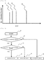
- Fig. 2 is a diagram illustrating an example of an outline of a mass spectrum graph of a chemical for a test (also referred to as reagent) of the invention.
- the indicator substance is added to the chemical for the test of a hazardous substance A so that the spectrum of peak 4 is sensed simultaneously with the mass spectrum of hazardous substance A as the mass spectrum of the indicator substance.
- the peak 1, the peak 2, and the peak 3 correspond to the components contained in the hazardous substance
- the peak 4 is used as a reagent indicator substance and is a component that is not normally contained in the hazardous substance.
- Fig. 3 is a diagram illustrating an example of a detection flow for distinguishing the chemical for the test from a real explosive. This operation is performed in the mass analysis unit 23 of the fine particle inspection device as the trace type hazardous substance sensing device. That is, the mass analysis unit 23 incorporates an electronic computer and software for operating the electronic calculator, or has the electronic computer and software externally, and the detection flow of Fig. 3 is executed by the software.
- Step 11 the analysis related to the sensing of the hazardous substance A is started.
- the fine particle inspection device is calibrated using the chemical for the test.
- Step 12 it is determined whether or not the hazardous substance A is sensed.
- mass spectra 1, 2, and 3 of the hazardous substance in Fig. 2 are sensed as mass spectra when the hazardous substance A is mass analyzed
- the chemical for the test of the hazardous substance A is input to the fine particle inspection device (trace type hazardous substance sensing device)
- peaks of the mass spectra of the hazardous substance 1, 2 and 3 in Fig. 2 are generated and it is determined as the hazardous substance.
- Step 16 If the hazardous substance A is not sensed in Step 12, it is determined in Step 16 that there is no detection target (hazardous substance A) and the fact of "no detection target" is displayed on a display device (not illustrated) . The flow is ended.
- Step 12 If the hazardous substance A is sensed in Step 12, it is determined in Step 13 whether a reagent indicator substance is sensed. That is, it is determined whether the peak 4 in Fig. 2 is detected.
- Step 15 If the reagent indicator substance is not sensed in Step 12, it is determined in Step 15 that the detection target (hazardous substance A) is detected. The fact that there was "detection target" is displayed on the display device (not illustrated). Here, since the peak 4 in Fig. 2 included in the reagent indicator substance used at the time of calibration is not detected, it is regarded that there is no influence of the reagent indicator substance. The flow is ended.
- Step 12 If the reagent indicator substance is sensed in Step 12, it is determined that the chemical for the test is included in Step 14 and the fact that "chemical for test" is detected is displayed on the display device (not illustrated) . The flow is ended.
- the peak 4 is set as the reagent indicator substance condition of the detection flow of Fig. 3 in the hazardous substance sensing device.
- Fig. 4 is a graph illustrating an example of a mass spectrum graph of fine particles of the pseudo hazardous substance to which an indicator substance DNT is added, instead of the chemical for the test illustrated in Fig. 2 .
- detection target hazardous substance
- added substance reagent indicator substance
- TNT contained 0.1% of TNT and 0.1% of DNT, and were prepared by injecting 200 ⁇ L of a DNT solution having a concentration of 0.1 ⁇ g/ ⁇ L diluted with acetone and drying for 2 days, so that DNT has DNT content of approximately 0.1% based on the total amount with respect to 20 mg of silica gel having a particle diameter of 20 to 30 ⁇ m/piece, to which 0.1% of TNT (trinitrotoluene) is attached.
- a DNT solution having a concentration of 0.1 ⁇ g/ ⁇ L diluted with acetone and drying for 2 days, so that DNT has DNT content of approximately 0.1% based on the total amount with respect to 20 mg of silica gel having a particle diameter of 20 to 30 ⁇ m/piece, to which 0.1% of TNT (trinitrotoluene) is attached.
- the trace type hazardous substance sensing device having a mass spectrometer When the fine particles of the pseudo hazardous substance to which DNT is added is measured with the trace type hazardous substance sensing device having a mass spectrometer, the peaks of two mass spectra are simultaneously measured, and DNT is simultaneously sensed for a regent that is sensed as TNT in the reagent alone of the fine particles of the pseudo hazardous substance. Therefore, it can be determined that the fine particles of the pseudo hazardous substance are being measured.
- acetone was used as an example this time.
- solvents or mixed solvents such as methanol, acetonitrile, ethanol, hexane, or the like may be used.
- other explosive particles such as RDX (hexogen) or PETN (pen slit) are used in the same manner as described above, it can be applied to other types of explosives.
- similar reagents can be prepared by adding an explosive solution to fine particles to which DNTs are attached rather than fine particles to which explosives are attached. Furthermore, after drying, it is dissolved again in a solvent such as acetone and dried again, so that it is likely to adhere to the silica gel. Silica gel is used this time.
- the reagent may be a solid or liquid such as glass beads, plastic beads, granules such as metal and ceramic.
- the indicator substance to be added may be a substance such as trichlorophenol (TCP) and tribromophenol (TBP) in addition to DNT, and any substance may be used as long as the substance in which the inspection target and the mass spectrum are not overlapped.
- Fig. 5 is a graph illustrating an example of a mass spectrum graph of the fine particles of the pseudo hazardous substance to which an indicator substance TCP is added.
- Fig. 5 illustrates a mass spectrum of the fine particles of the pseudo hazardous substance having 0.1% of TNT and 0.1% of TCP %, prepared by the same technique as DNT.
- DNT it is possible to determine that peaks of two mass spectra derived from an explosive and an indicator substance are simultaneously measured, and the fine particles of the pseudo hazardous substance are measured. Particularly, in a case where a plurality of peaks are detected as in TCP, it is more likely to determine that it is derived from the indicator substance.
- the technique of adding the indicator substance it is possible to add the indicator substance not only in a solid such as silica gel but also in a solution.
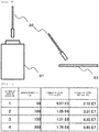
- Fig. 6 is a diagram illustrating an example of a technique for attaching the fine particles quantitatively on a card. It is not easy to attach an amount that cannot be measured with an electronic balance or the like on the card.
- a technique of putting a cotton swab 32 in a container 31 containing the fine particles of the pseudo hazardous substance as illustrated in Fig. 6 attaching the fine particles of the pseudo hazardous substance to the tip end of the cotton swab 32, and attaching the cotton swab to the surface of the card 33 (used as inspection target 18 in Fig. 1 ) with the fine particles of the pseudo hazardous substance attached to the tip end thereof, the adhesion amount can be controlled by the area of the tip end of the cotton swab 32.
- Fig. 7 is a table illustrating an example of the number of times the fine particles are attached to the card with a cotton swab and a mass spectrum intensity.
- Fig. 7 illustrates the adhesion amount and the signal intensity of the detected mass spectrum when the fine particles of the pseudo hazardous substance with TNT of 0.1% and DNT of 0.1% are attached to the card surface by the above-described technique using the cotton swab with a tip of ⁇ 2.0 and inspected by the device of Fig. 6 .
- the fine particles of the pseudo hazardous substance to be attached this time are the fine particles of the pseudo hazardous substance to which the indicator substance of the invention is added, since false alarms are not issued even if the fine particles of the pseudo hazardous substance adheres to the periphery of the device and erroneously enters during inspection at the time of operation, it is possible to prevent a decrease in throughput.
- description is made using the cotton swab of ⁇ 2.0 in the example. Alternatively, by changing the size of the cotton swab, the adhesion amount can be changed.
- Fig. 8 is a diagram illustrating an example of a method of attaching the fine particles to the card. Attachment to the inspection target with the cotton swab was described this time. Alternatively, by attaching the fine particles of the pseudo hazardous substance 35 to an adhesive one such as the seal 34 as illustrated in Fig. 8 and transferring to the card 33, it is possible to attach the fine particles of the pseudo hazardous substance 35 to the inspection target.
- the adhesion target is a card. Alternatively, the adhesion target may be attached to another inspection target such as a bag, a card holder, clothes, a hand or the like. In the example, the cotton swab is used.
- a portion having a controlled tip area such as metal, paper, wood, plastic, ceramic, adhesive material or the like may be used.
- the fine particles of the pseudo hazardous substance prepared with silica gel this time are described.
- a certain amount of other individual fine particles can be attached to the inspection target in the same manner.
- FIG. 9 is a diagram illustrating an example of a technique for quantitatively attaching the fine particles to the card (used as inspection target 18 in Fig. 1 ).
- the technique of Example 3 it is possible to simply attach minute amounts of fine particles to the card.
- adhesion amount by the inspector there are many variations in adhesion amount by the inspector, so that to use for sensitivity confirmation that requires quantitative evaluation, error is large and accuracy is poor.
- the card holder 22 in which holes are opened as illustrated in Fig. 9 was used.
- the card holder 42 is prepared in which one or a plurality of non-penetrating holes 41 are opened on the card surface.
- the hole After filling the hole 41 with fine particles for inspection and eliminating excess fine particles with a spatula 43 or the like, the hole is closed with a lid 46 and extra fine particles on the card holder are cleaned with a brush 44, air 45 or the like around the periphery.
- the amount of fine particles on the card can be set to a fixed amount, and quantitative sensitivity confirmation can be performed.
- Fig. 10 is a diagram illustrating an example of a technique for quantitatively attaching the fine particles to the card.
- a sheet 47 in which a hole 48 is opened may be pasted.
- the positions of the holes are also near the center in Fig. 9 .
- the positions of the holes are not limited.
- the card holder is used as a description.
- the inspection target may be attached to another inspection target such as a bag or clothing.
- Fig. 11 is a diagram illustrating an example of a mechanism for quantitatively attaching the fine particles to the card. If the structure is such that the hole 52 can be covered with a slide 51 as illustrated in Fig. 11 , by sliding the slide 51, since an effect equivalent to that of the spatula 43 can be obtained and can be simultaneously covered, so that the work to be performed with the spatula and the lid can be simultaneously performed.
- Fig. 12 is a diagram illustrating an example of a mechanism for quantitatively attaching the fine particles to the card. In Fig. 11 , a sliding mechanism is described as being in a shape of a circle. Alternatively, any shape such as square, rhombus or the like is acceptable, as long as the container is maintained as illustrated in Fig. 12 .
- the slide in the rotation direction is used. Alternatively, it may be slid laterally or slid in the vertical direction as illustrated in Fig. 12 , or the rotation shaft may not be at the center.
- a sheet may be stuck on the surface of the inspection target as described above.
- the inspection can be performed on the spot even in an environment where it is difficult to fill the fine particles.
- the above-described embodiment describes the mass spectrum and the detection flow in detail and concretely in order to describe the invention easily, and it is not necessarily limited to those having all the configurations described.
- the configuration of another Example can be added to the configuration of one Example.
Landscapes
- Chemical & Material Sciences (AREA)
- Analytical Chemistry (AREA)
- Life Sciences & Earth Sciences (AREA)
- Health & Medical Sciences (AREA)
- Engineering & Computer Science (AREA)
- Physics & Mathematics (AREA)
- Biochemistry (AREA)
- General Health & Medical Sciences (AREA)
- General Physics & Mathematics (AREA)
- Immunology (AREA)
- Pathology (AREA)
- Food Science & Technology (AREA)
- Medicinal Chemistry (AREA)
- Combustion & Propulsion (AREA)
- Other Investigation Or Analysis Of Materials By Electrical Means (AREA)
- Chemical Kinetics & Catalysis (AREA)
- Electrochemistry (AREA)
Abstract
Description
- The present invention relates to a chemical for a test used in a hazardous substance sensing device, a hazardous substance sensing device, and a hazardous substance sensing method.
- A threat of terrorism is globally increased and countermeasures against terrorism due to a hazardous substance such as explosives are required for important facilities such as a nuclear power plant. As a method of manufacturing the explosives using everyday goods is widely known, terrorism and crime due to the explosives are a threat in daily life. Simultaneous multiple terror aimed at subways and buses globally occurred and numerous casualties were reported. In addition, a case such as arresting a suspect who tried suicide bombing inside the commuter train is reported.
- As a device for sensing such hazardous substance, there is known a device in which an inspection target is sampled, the inspection target is mass analyzed by applying a mass spectrometry technique, and the fact that the hazardous substance is detected is displayed on a display, when a substance corresponding to an ion of the hazardous substance is detected in a mass analysis result.
- Such a technique is described, for example, in
JP-A-2000-28579 - PTL 1:
JP-A-2000-28579 - In routine checking of the soundness of the device, for example, in a trace type hazardous substance sensing device having a mass spectrometer, the operation of the device is confirmed in many cases by inputting a reagent containing the same substance as a hazardous substance. In particular, in a case where the reagent containing the same substance as the hazardous substance is input, the same mass spectrum as the hazardous substance is measured. However, in a case where a hazardous substance reagent is used for operation confirmation, there is a possibility that the hazardous substance reagent may remain in the device. There was a problem that it was impossible to distinguish between erroneous sensing due to the hazardous substance reagent remaining when the hazardous substance was sensed during operation and sensing of the hazardous substance due to a real hazardous substance. As a result, it is expected that the erroneous sensing occurs frequently due to the hazardous substance reagent adhering to a periphery of the device after performing the operation confirmation. In particular, in facilities where thousands or tens of thousands of people go through each day, reduction in throughput due to the erroneous sensing is a big problem, so that it is extremely important to suppress the erroneous sensing by the unnecessary hazardous substance reagent.
- Although it is one method to prevent false alarms during operation by confirming the operation of the device by inputting a substance different from the hazardous substance, in order to confirm the reliable performance, it is necessary to confirm the operation of the device by putting the same substance as an inspection target.
- In addition, there is a technique of adhering to the inspection target with a pen or the like containing a reagent solution in a normal hazardous substance sensing device. However, there was a problem that it is difficult to adhere the reagent quantitatively to the inspection target.
- An object of the present invention is to provide a chemical for a test used in a hazardous substance sensing device, a hazardous substance sensing device, and a hazardous substance sensing method capable of suppressing malfunction even in a case where a reagent (reagent chemical) corresponding to a hazardous substance is used.
- In the invention, in order to achieve the above object, there is provided a hazardous substance sensing device using a reagent chemical to which an indicator substance different from a hazardous substance as a detection target is added and calibrated based on the detection target included in the reagent chemical, the device including an analysis unit performing mass analysis, and a determination unit determining that the detection target is included, in a case where a peak corresponding to the indicator substance is not included and a peak corresponding to the substance as the detection target is included in a spectrum as an analysis result of the analysis unit.
- Alternatively, a chemical for a test of a hazardous substance sensing device, including a hazardous substance as a detection target, and an additional substance as an indicator substance different from the hazardous substance.
- Specifically, when the hazardous substance reagent is input to the trace type hazardous substance sensing device having a mass spectrometer used for the hazardous substance sensing, a technique that can distinguish whether the hazardous substance reagent is a real hazardous substance or a remaining hazardous substance reagent is proposed. The trace type hazardous substance sensing device mainly determines the substance contained in an inspection substance from the obtained mass spectrum from the result of generating ions from the inspection substance and performing mass analysis. Therefore, the indicator substance is added to the hazardous substance reagent so that the mass spectrum which does not originally occur in a case where the hazardous substance is inspected is measured. Therefore, even in a case where the hazardous substance reagent is inspected, a mass spectrum different from a mass spectrum of the hazardous substance is measured, and it can be determined that the inspected substance is the hazardous substance reagent. This technique can be applied not only to a solution but also to solids such as fine particles.
- According to the invention, even in a case where the reagent corresponding to the hazardous substance is used, malfunction can be suppressed.
-
-
Fig. 1 is a diagram illustrating an example of a configuration of a fine particle inspection device as a trace type hazardous substance sensing device. -
Fig. 2 is a diagram illustrating an example of an outline of a mass spectrum graph. -
Fig. 3 is a flow illustrating an example of a detection flow of the trace type hazardous substance sensing device. -
Fig. 4 is a graph illustrating an example of a mass spectrum graph of fine particles of a pseudo hazardous substance to which an indicator substance DNT is added. -
Fig. 5 is a graph illustrating an example of a mass spectrum graph of fine particles of a pseudo hazardous substance to which an indicator substance TCP is added. -
Fig. 6 is a diagram illustrating an example of a technique for attaching fine particles quantitatively on a card. -
Fig. 7 is a table illustrating an example of the number of times the fine particles are attached to the card with a cotton swab and a mass spectrum intensity. -
Fig. 8 is a diagram illustrating an example of a method of attaching the fine particles to the card. -
Fig. 9 is a diagram illustrating an example of a technique for quantitatively attaching the fine particles to the card. -
Fig. 10 is a diagram illustrating an example of a technique for quantitatively attaching the fine particles to the card. -
Fig. 11 is a diagram illustrating an example of a mechanism for quantitatively attaching the fine particles to the card. -
Fig. 12 is a diagram illustrating an example of a mechanism for quantitatively attaching the fine particles to the card. -
Fig. 13 is a diagram illustrating an example of a method of providing a jig to which the fine particles are attached. - As a mode for performing the invention, a chemical for a test used in a trace type hazardous substance sensing device, an inspection technique, and a detection flow will be described in detail with reference to the drawings.
- First, a basic concept will be described. A mass spectrum of a hazardous substance sensing and a mass spectrum of a reagent indicator substance sensing are set in the trace type hazardous substance sensing device, and even in a case where the mass spectrum of the hazardous substance sensing is sensed at the time of inspecting the hazardous substance, in a case where the mass spectrum of the reagent indicator substance sensing is sensed simultaneously, immediately before, or immediately after, a configuration of an alarm condition such as excluding from the alarm condition of the hazardous substance sensing is adopted. Therefore, a chemical for a test is excluded from an alarm and it is possible to prevent erroneous sensing due to the chemical for the test during operation. Therefore, even if the chemical for the test is mistakenly mixed in the operation of the trace type hazardous substance sensing device, it is possible to determine that it is the chemical for the test without determining it as the hazardous substance.
- In addition, by adding an indicator substance so that mass spectra of a plurality of indicator substances is measured in the chemical for the test, a plurality of patterns of mass spectra of the hazardous substance reagent can be prepared, and it is possible to prevent illegal carry-in of the hazardous substance due to the determination of the indicator substance. Therefore, by changing a combination of additive substances according to the installation environment and operation situation, even if one pattern of additional substance is specified, it is possible to prevent expansion of illegal carry-in.
- An example of a fine particle inspection method as a trace type hazardous substance sensing will be described for an example of the invention.
Fig. 1 is a diagram illustrating an example of a configuration of a fine particle inspection device as a trace type hazardous substance sensing device. InFig. 1 , gas and/or fine particles of a detection target substance attached to aninspection target 18 above anauthentication unit 19 is separated by an air flow from anair supply unit 17. A separated sample is sucked from asuction port 20, condensed and collected by a fineparticle collection unit 21. Ions of the sample are generated by anion source unit 22, and amass analysis unit 23 performs mass analysis. A cyclone, a filter, and an impactor may be used for the fine particle collection unit. It is for determining the presence or absence of a mass spectrum derived from the detection target substance from the obtained mass spectrum. In addition, not only an intensity but also a mass axis can be adjusted by the collected sample. Acalibrant generator 24 is used for confirming the operation of the device, correcting the intensity of the mass spectrum, or adjusting the mass axis by generating a certain amount of calibration gas by inserting the calibration substance. As an example of a calibration substance, lactic acid, tribromorescorcinol, and bromochlorophenol are used for measurement of negative ions, and 3'-nitroacetophenone is used for measurement of positive ions. In the above description, four types of calibration substances are described as an example, and other calibration substances may be used if a calibration gas is generated. In addition, these calibration substances may be used as dopants. Thecalibrant generator 24 may be used only by a combination of theion source 22 and themass analysis unit 23. - In order to confirm the soundness of the device, it is necessary to confirm whether or not the fine particles of the hazardous substance attached to the card can be collected. Therefore, it is desirable for the device in
Fig. 1 to inspect whether the reagent can be sensed by inspection flow by attaching a small amount of reagent to theinspection target 18 when checking the soundness. - In the example, a mass spectrometer is used as an explanation. Alternatively, other methods such as a linear ion trap mass spectrometer, a quadrupole ion trap mass spectrometer, a triple quadrupole mass spectrometer, a time-of-flight type mass spectrometer, a magnetic field type mass spectrometer, and an ion mobility may be used as an analysis method.
-
Fig. 2 is a diagram illustrating an example of an outline of a mass spectrum graph of a chemical for a test (also referred to as reagent) of the invention. The indicator substance is added to the chemical for the test of a hazardous substance A so that the spectrum ofpeak 4 is sensed simultaneously with the mass spectrum of hazardous substance A as the mass spectrum of the indicator substance. - The chemical for the test is a chemical for a test such that peak 1 (count A1, mass (m/z) = B1), peak 2 (count A2, mass B2), peak 3 (count A3, mass B3), and peak 4 (count A4, mass A4) are output if the fine particle inspection device (trace type hazardous substance sensing device) is in a state that can be analyzed with correct accuracy. Here, the
peak 1, thepeak 2, and thepeak 3 correspond to the components contained in the hazardous substance, and thepeak 4 is used as a reagent indicator substance and is a component that is not normally contained in the hazardous substance. - Before identifying the hazardous substance A with the fine particle inspection device, the fine particle inspection device is calibrated using the chemical for the test. That is, in a case where the result of analyzing the chemical for the test with the fine particle inspection device is different from the spectrum illustrated in
Fig. 2 in count (amount on vertical axis illustrated inFig. 2 ) and mass (amount on horizontal axis illustrated inFig. 2 ), the parameters of the fine particle inspection device are adjusted and the parameters are adjusted until the same (or substantially the same) spectrum as the spectrum illustrated inFig. 2 is output (until (count A1, mass (m/z) = B1), (count A2, mass B2), (count A3, mass B3), and (count A4, mass A4) are output). -
Fig. 3 is a diagram illustrating an example of a detection flow for distinguishing the chemical for the test from a real explosive. This operation is performed in themass analysis unit 23 of the fine particle inspection device as the trace type hazardous substance sensing device. That is, themass analysis unit 23 incorporates an electronic computer and software for operating the electronic calculator, or has the electronic computer and software externally, and the detection flow ofFig. 3 is executed by the software. - In Step 11, the analysis related to the sensing of the hazardous substance A is started. Here, at the start of the analysis, it is premised that the fine particle inspection device is calibrated using the chemical for the test.
- In
Step 12, it is determined whether or not the hazardous substance A is sensed. In a case wheremass spectra Fig. 2 are sensed as mass spectra when the hazardous substance A is mass analyzed, when the chemical for the test of the hazardous substance A is input to the fine particle inspection device (trace type hazardous substance sensing device), peaks of the mass spectra of thehazardous substance Fig. 2 are generated and it is determined as the hazardous substance. - If the hazardous substance A is not sensed in
Step 12, it is determined inStep 16 that there is no detection target (hazardous substance A) and the fact of "no detection target" is displayed on a display device (not illustrated) . The flow is ended. - If the hazardous substance A is sensed in
Step 12, it is determined inStep 13 whether a reagent indicator substance is sensed. That is, it is determined whether thepeak 4 inFig. 2 is detected. - If the reagent indicator substance is not sensed in
Step 12, it is determined inStep 15 that the detection target (hazardous substance A) is detected. The fact that there was "detection target" is displayed on the display device (not illustrated). Here, since thepeak 4 inFig. 2 included in the reagent indicator substance used at the time of calibration is not detected, it is regarded that there is no influence of the reagent indicator substance. The flow is ended. - If the reagent indicator substance is sensed in
Step 12, it is determined that the chemical for the test is included inStep 14 and the fact that "chemical for test" is detected is displayed on the display device (not illustrated) . The flow is ended. - In this manner, the
peak 4 is set as the reagent indicator substance condition of the detection flow ofFig. 3 in the hazardous substance sensing device. As a result, even if the hazardous substance A is sensed, it can be determined that the hazardous substance A is the chemical for the test by sensing the indicator substance. - As another application example, an example used as a reference for cleaning after confirming the soundness of the device will be described. In a case where the spectrum of
peak 4 is detected, it is determined that the chemical for the test remains. Therefore, physical cleaning such as heating temperature rise, air blowing, wiping off or the like is performed until thepeak 4 disappears. - An example when DNT (dinitrotoluene) is added as an indicator substance for Example 2 of the invention will be described. Differences from Example 1 will be described. Therefore, a portion in which the description is omitted is similar to Example 1.
Fig. 4 is a graph illustrating an example of a mass spectrum graph of fine particles of the pseudo hazardous substance to which an indicator substance DNT is added, instead of the chemical for the test illustrated inFig. 2 . In the flow illustrated inFig. 2 , the following detection target (hazardous substance) and added substance (reagent indicator substance) are used. The fine particles of the pseudo hazardous substance illustrated inFig. 4 contained 0.1% of TNT and 0.1% of DNT, and were prepared by injecting 200 µL of a DNT solution having a concentration of 0.1 µg/µL diluted with acetone and drying for 2 days, so that DNT has DNT content of approximately 0.1% based on the total amount with respect to 20 mg of silica gel having a particle diameter of 20 to 30 µm/piece, to which 0.1% of TNT (trinitrotoluene) is attached. When the fine particles of the pseudo hazardous substance to which DNT is added is measured with the trace type hazardous substance sensing device having a mass spectrometer, the peaks of two mass spectra are simultaneously measured, and DNT is simultaneously sensed for a regent that is sensed as TNT in the reagent alone of the fine particles of the pseudo hazardous substance. Therefore, it can be determined that the fine particles of the pseudo hazardous substance are being measured. - For a diluted solution of an additional indicator substance, acetone was used as an example this time. Alternatively, other solvents or mixed solvents such as methanol, acetonitrile, ethanol, hexane, or the like may be used. If other explosive particles such as RDX (hexogen) or PETN (pen slit) are used in the same manner as described above, it can be applied to other types of explosives. In addition, similar reagents can be prepared by adding an explosive solution to fine particles to which DNTs are attached rather than fine particles to which explosives are attached. Furthermore, after drying, it is dissolved again in a solvent such as acetone and dried again, so that it is likely to adhere to the silica gel. Silica gel is used this time. Alternatively, if it is possible to attach the reagent, it may be a solid or liquid such as glass beads, plastic beads, granules such as metal and ceramic. The indicator substance to be added may be a substance such as trichlorophenol (TCP) and tribromophenol (TBP) in addition to DNT, and any substance may be used as long as the substance in which the inspection target and the mass spectrum are not overlapped. By increasing the number of substances to be added to the reagent to multiple, the mass spectrum of the reagent indicator can be increased.
-
Fig. 5 is a graph illustrating an example of a mass spectrum graph of the fine particles of the pseudo hazardous substance to which an indicator substance TCP is added.Fig. 5 illustrates a mass spectrum of the fine particles of the pseudo hazardous substance having 0.1% of TNT and 0.1% of TCP %, prepared by the same technique as DNT. Similarly to DNT, it is possible to determine that peaks of two mass spectra derived from an explosive and an indicator substance are simultaneously measured, and the fine particles of the pseudo hazardous substance are measured. Particularly, in a case where a plurality of peaks are detected as in TCP, it is more likely to determine that it is derived from the indicator substance. In the technique of adding the indicator substance, it is possible to add the indicator substance not only in a solid such as silica gel but also in a solution. - Example 3 is described.
Fig. 6 is a diagram illustrating an example of a technique for attaching the fine particles quantitatively on a card. It is not easy to attach an amount that cannot be measured with an electronic balance or the like on the card. By using a technique of putting acotton swab 32 in acontainer 31 containing the fine particles of the pseudo hazardous substance as illustrated inFig. 6 , attaching the fine particles of the pseudo hazardous substance to the tip end of thecotton swab 32, and attaching the cotton swab to the surface of the card 33 (used asinspection target 18 inFig. 1 ) with the fine particles of the pseudo hazardous substance attached to the tip end thereof, the adhesion amount can be controlled by the area of the tip end of thecotton swab 32. -
Fig. 7 is a table illustrating an example of the number of times the fine particles are attached to the card with a cotton swab and a mass spectrum intensity.Fig. 7 illustrates the adhesion amount and the signal intensity of the detected mass spectrum when the fine particles of the pseudo hazardous substance with TNT of 0.1% and DNT of 0.1% are attached to the card surface by the above-described technique using the cotton swab with a tip of Φ 2.0 and inspected by the device ofFig. 6 . At this time, it can be understood that approximately 50 µg of fine particles containing approximately 50 ng of TNT and approximately 50 ng of DNT per one adhesion of the cotton swab are attached to the card, the adhesion number and the signal intensity of the mass spectrum are in a proportional relationship, and a certain amount of the fine particles of the pseudo hazardous substance of tens of micro order on the surface of thecard 33 is attached. If the fine particles of the pseudo hazardous substance to be attached this time are the fine particles of the pseudo hazardous substance to which the indicator substance of the invention is added, since false alarms are not issued even if the fine particles of the pseudo hazardous substance adheres to the periphery of the device and erroneously enters during inspection at the time of operation, it is possible to prevent a decrease in throughput. In addition, description is made using the cotton swab of Φ 2.0 in the example. Alternatively, by changing the size of the cotton swab, the adhesion amount can be changed. -
Fig. 8 is a diagram illustrating an example of a method of attaching the fine particles to the card. Attachment to the inspection target with the cotton swab was described this time. Alternatively, by attaching the fine particles of the pseudohazardous substance 35 to an adhesive one such as theseal 34 as illustrated inFig. 8 and transferring to thecard 33, it is possible to attach the fine particles of the pseudohazardous substance 35 to the inspection target. In the example, the adhesion target is a card. Alternatively, the adhesion target may be attached to another inspection target such as a bag, a card holder, clothes, a hand or the like. In the example, the cotton swab is used. Alternatively, a portion having a controlled tip area such as metal, paper, wood, plastic, ceramic, adhesive material or the like may be used. In addition, the fine particles of the pseudo hazardous substance prepared with silica gel this time are described. Alternatively, a certain amount of other individual fine particles can be attached to the inspection target in the same manner. - An example of attaching quantitative fine particles to the inspection target for Example 4 of the invention will be described.
Fig. 9 is a diagram illustrating an example of a technique for quantitatively attaching the fine particles to the card (used asinspection target 18 inFig. 1 ). When the technique of Example 3 is used, it is possible to simply attach minute amounts of fine particles to the card. Alternatively, there are many variations in adhesion amount by the inspector, so that to use for sensitivity confirmation that requires quantitative evaluation, error is large and accuracy is poor. In order to solve this problem, thecard holder 22 in which holes are opened as illustrated inFig. 9 was used. As illustrated inFig. 9 , thecard holder 42 is prepared in which one or a plurality ofnon-penetrating holes 41 are opened on the card surface. After filling thehole 41 with fine particles for inspection and eliminating excess fine particles with aspatula 43 or the like, the hole is closed with alid 46 and extra fine particles on the card holder are cleaned with abrush 44,air 45 or the like around the periphery. As a result, since only the fine particles corresponding to the volume of the hole remain on thecard holder 42, the amount of fine particles on the card can be set to a fixed amount, and quantitative sensitivity confirmation can be performed. -
Fig. 10 is a diagram illustrating an example of a technique for quantitatively attaching the fine particles to the card. In a case where it is difficult to prepare the card or the card holder in which the holes are opened, as illustrated inFig. 10 , asheet 47 in which ahole 48 is opened may be pasted. The positions of the holes are also near the center inFig. 9 . Alternatively, the positions of the holes are not limited. The card holder is used as a description. Alternatively, the inspection target may be attached to another inspection target such as a bag or clothing. - In addition,
Fig. 11 is a diagram illustrating an example of a mechanism for quantitatively attaching the fine particles to the card. If the structure is such that thehole 52 can be covered with aslide 51 as illustrated inFig. 11 , by sliding theslide 51, since an effect equivalent to that of thespatula 43 can be obtained and can be simultaneously covered, so that the work to be performed with the spatula and the lid can be simultaneously performed.Fig. 12 is a diagram illustrating an example of a mechanism for quantitatively attaching the fine particles to the card. InFig. 11 , a sliding mechanism is described as being in a shape of a circle. Alternatively, any shape such as square, rhombus or the like is acceptable, as long as the container is maintained as illustrated inFig. 12 . InFig. 11 , the slide in the rotation direction is used. Alternatively, it may be slid laterally or slid in the vertical direction as illustrated inFig. 12 , or the rotation shaft may not be at the center. In a case where it is difficult to drill a hole in the inspection target, a sheet may be stuck on the surface of the inspection target as described above. In addition, in a case where it is difficult to fill the reagent fine particles at the inspection site, by previously filling the fine particles and previously covering with a sheet or the like as thelid 46 as illustrated in the figure illustrating an example of a method of providing a jig to which the fine particles are attached inFig. 13 , the inspection can be performed on the spot even in an environment where it is difficult to fill the fine particles. - The invention is not limited to the embodiments described above and it goes without saying that various other applications and modifications can be made without departing from the gist of the invention described in the aspects.
- For example, the above-described embodiment describes the mass spectrum and the detection flow in detail and concretely in order to describe the invention easily, and it is not necessarily limited to those having all the configurations described. In addition, it is possible to replace a portion of the configuration of one Example with the configuration of another Example. Furthermore, the configuration of another Example can be added to the configuration of one Example. In addition, it is also possible to add, delete, and replace other configurations with respect to a portion of the configuration of each Example.
-
- 1
- mass spectrum of hazardous substance
- 2
- mass spectrum of hazardous substance
- 3
- mass spectrum of hazardous substance
- 4
- mass spectrum of indicator substance
- 10
- start of measurement
- 12
- presence or absence of hazardous substance sensing
- 13
- presence or absence of indicator substance sensing
- 14
- reagent sensing
- 15
- hazardous substance sensing
- 16
- absence of hazardous substance
- 17
- air supply unit
- 18
- inspection target
- 19
- authentication unit
- 20
- suction unit
- 21
- collection unit
- 22
- ion source unit
- 23
- mass analysis unit
- 24
- calibrant generator
- 31
- container
- 32
- cotton swab
- 33
- card
- 41
- reagent filling hole
- 42
- card holder
- 43
- spatula
- 44
- air supply unit
- 45
- spatula
- 46
- lid
- 47
- sheet
- 48
- reagent filling hole
- 51
- sliding mechanism
- 52
- reagent filling hole
- 53
- inspection target
Claims (9)
- A hazardous substance sensing device using a reagent chemical to which an indicator substance different from a hazardous substance as a detection target is added and calibrated based on the detection target included in the reagent chemical, the device comprising:an analysis unit performing mass analysis; anda determination unit determining that the detection target is included, in a case where a peak corresponding to the indicator substance is not included and a peak corresponding to the substance as the detection target is included in a spectrum as an analysis result of the analysis unit.
- The hazardous substance sensing device according to Claim 1, further comprising:
a fine particle collection unit for collecting the substance as the detection target and the reagent indicator substance. - The hazardous substance sensing device according to Claims 1 or 2,
wherein fine particles are used as the reagent indicator substance. - The hazardous substance sensing device according to any one of Claims 1 to 3,
wherein the analysis unit is configured to include any one of a linear ion trap mass spectrometer, a quadrupole ion trap mass spectrometer, a triple quadrupole mass spectrometer, a time-of-flight type mass spectrometer, a magnetic field type mass spectrometer, and an ion mobility. - The hazardous substance sensing device according to Claim 1,
wherein the reagent indicator substance is supplied by being attached to a jig capable of holding the reagent indicator substance in a certain area. - The hazardous substance sensing device according to Claim 1,
wherein the reagent indicator substance is supplied by being attached to a jig capable of holding reagent indicator substance in a certain volume. - The hazardous substance sensing device according to Claim 6,
wherein a lid is provided on the jig. - A hazardous substance sensing method comprising:using a reagent chemical to which an indicator substance different from a hazardous substance as a detection target is added and performing calibration based on the detection target included in the reagent chemical;performing mass analysis; anddetermining that the detection target is included, in a case where a peak corresponding to the indicator substance is not included and a peak corresponding to the substance as the detection target is included in a spectrum as an analysis result.
- A chemical for a test of a hazardous substance sensing device, comprising:a hazardous substance as a detection target; andan additional substance as an indicator substance different from the hazardous substance.
Applications Claiming Priority (2)
| Application Number | Priority Date | Filing Date | Title |
|---|---|---|---|
| JP2016117580A JP6710108B2 (en) | 2016-06-14 | 2016-06-14 | Chemicals for testing dangerous goods detection equipment, dangerous goods detection equipment and dangerous goods detection method |
| PCT/JP2017/015082 WO2017217096A1 (en) | 2016-06-14 | 2017-04-13 | Chemical for test used in hazardous substance sensing device, hazardous substance sensing device, and hazardous substance sensing method |
Publications (3)
| Publication Number | Publication Date |
|---|---|
| EP3470831A1 true EP3470831A1 (en) | 2019-04-17 |
| EP3470831A4 EP3470831A4 (en) | 2020-03-11 |
| EP3470831B1 EP3470831B1 (en) | 2023-05-24 |
Family
ID=60664335
Family Applications (1)
| Application Number | Title | Priority Date | Filing Date |
|---|---|---|---|
| EP17813002.7A Active EP3470831B1 (en) | 2016-06-14 | 2017-04-13 | Hazardous substance sensing device and method |
Country Status (5)
| Country | Link |
|---|---|
| US (1) | US10955401B2 (en) |
| EP (1) | EP3470831B1 (en) |
| JP (1) | JP6710108B2 (en) |
| CN (1) | CN109073594B (en) |
| WO (1) | WO2017217096A1 (en) |
Families Citing this family (2)
| Publication number | Priority date | Publication date | Assignee | Title |
|---|---|---|---|---|
| JP7446487B2 (en) | 2021-01-19 | 2024-03-08 | 株式会社日立ハイテク | particle separator |
| JP2023088420A (en) * | 2021-12-15 | 2023-06-27 | 株式会社日立製作所 | Analyzer, Hazardous Material Detector, and Selection Screen Interface |
Family Cites Families (21)
| Publication number | Priority date | Publication date | Assignee | Title |
|---|---|---|---|---|
| CA1109706A (en) | 1980-02-04 | 1981-09-29 | Joseph R. Bonnycastle | Explosive booster manufacture |
| CN1162993A (en) * | 1994-08-20 | 1997-10-22 | 雷尼肖公司 | detector for explosives |
| JP2000028579A (en) | 1998-07-08 | 2000-01-28 | Hitachi Ltd | Sample gas sampling device and dangerous substance detection device |
| JP4356410B2 (en) * | 2003-09-22 | 2009-11-04 | 株式会社日立製作所 | Chemical substance detection apparatus and chemical substance detection method |
| US7751999B1 (en) * | 2005-04-12 | 2010-07-06 | The United States Of America As Represented By The Secretary Of The Navy | Method and system for field calibrating an ion mobility spectrometer or other trace vapor detection instrument |
| US8173959B1 (en) | 2007-07-21 | 2012-05-08 | Implant Sciences Corporation | Real-time trace detection by high field and low field ion mobility and mass spectrometry |
| JP5183221B2 (en) * | 2008-01-22 | 2013-04-17 | 株式会社日立製作所 | Security system, security center apparatus, and security management method |
| US8067731B2 (en) * | 2008-03-08 | 2011-11-29 | Scott Technologies, Inc. | Chemical detection method and system |
| CN101644686B (en) | 2008-08-08 | 2013-07-24 | 李海洋 | United on-line detector for explosive and poison and application thereof |
| US8237118B2 (en) * | 2008-08-21 | 2012-08-07 | University Of Florida Research Foundation, Inc. | Partial ovoidal FAIMS electrode |
| CN101498705A (en) * | 2009-02-18 | 2009-08-05 | 王利兵 | Nitryl suspicious explosive intelligent detector based on chemical sensor array technology |
| JP2011117885A (en) | 2009-12-07 | 2011-06-16 | Hitachi High-Tech Control Systems Corp | Foreign substance detection method and foreign substance detection device |
| CN101949889B (en) * | 2010-08-10 | 2012-10-17 | 公安部第三研究所 | Ion mobility spectrometry detection device for narcotics and explosives |
| CN105223043B (en) * | 2010-11-11 | 2017-12-19 | 株式会社日立制作所 | Particle capture device |
| CN103512946B (en) * | 2012-06-29 | 2015-09-23 | 中国科学院大连化学物理研究所 | A kind of ion mobility spectrometry is by the method for time variant voltage pattern-recognition explosive |
| CN103884770B (en) * | 2012-12-19 | 2016-12-28 | 中国科学院大连化学物理研究所 | A kind of detection method of explosive |
| CN103399075B (en) * | 2013-07-25 | 2015-06-17 | 中国科学院生态环境研究中心 | Double-mode detecting method and kit for detecting for organic explosive residues |
| EP3132250B1 (en) * | 2014-04-17 | 2020-05-06 | Battelle Memorial Institute | Explosives detection using raman spectroscopy |
| US8921774B1 (en) * | 2014-05-02 | 2014-12-30 | 908 Devices Inc. | High pressure mass spectrometry systems and methods |
| CN104122298A (en) * | 2014-06-25 | 2014-10-29 | 安徽芯核防务装备技术股份有限公司 | Gas sensitive element and gas sensitive sensor for monitoring dangerous goods in public traffic safety |
| US9726655B2 (en) * | 2014-09-22 | 2017-08-08 | Morpho Detection, Llc | Selective ion chemistry for nitrate detection |
-
2016
- 2016-06-14 JP JP2016117580A patent/JP6710108B2/en active Active
-
2017
- 2017-04-13 US US16/309,310 patent/US10955401B2/en not_active Expired - Fee Related
- 2017-04-13 EP EP17813002.7A patent/EP3470831B1/en active Active
- 2017-04-13 WO PCT/JP2017/015082 patent/WO2017217096A1/en not_active Ceased
- 2017-04-13 CN CN201780024019.1A patent/CN109073594B/en not_active Expired - Fee Related
Also Published As
| Publication number | Publication date |
|---|---|
| EP3470831A4 (en) | 2020-03-11 |
| JP2017223482A (en) | 2017-12-21 |
| US20190178865A1 (en) | 2019-06-13 |
| CN109073594B (en) | 2022-08-19 |
| WO2017217096A1 (en) | 2017-12-21 |
| EP3470831B1 (en) | 2023-05-24 |
| JP6710108B2 (en) | 2020-06-17 |
| US10955401B2 (en) | 2021-03-23 |
| CN109073594A (en) | 2018-12-21 |
Similar Documents
| Publication | Publication Date | Title |
|---|---|---|
| US10281366B2 (en) | Sampling device including mechanical force feedback mechanism | |
| US20160161413A1 (en) | System and method for detection of contaminants | |
| CN101858897A (en) | Detection method of phthalate plasticizer | |
| CN107807178A (en) | Septicemia product and resisting mental disease class medicine liquid chromatography-mass spectrography detection method | |
| EP3470831B1 (en) | Hazardous substance sensing device and method | |
| Namieśnik et al. | Preparation of environmental samples for the determination of trace constituents | |
| Couch et al. | Development of a novel seized drug screening method utilizing DART-MS and used weigh paper | |
| Pueyo et al. | A new organic-rich soil reference material certified for its EDTA-and acetic acid-extractable contents of Cd, Cr, Cu, Ni, Pb and Zn, following collaboratively tested and harmonised procedures | |
| CN103852499B (en) | Illegal method of adding biguanides in quick detection goods | |
| CN103424388B (en) | A kind of TNT colorimetric fluorescent detection probe and application process thereof | |
| JP2006284378A (en) | Simple analysis method for heavy metals in crops | |
| Butler et al. | Analytical protocol for the sensitive determination of mannitol, sorbitol and glucose containing powders in pharmaceutical workplaces by ion chromatography using a pulsed amperometric detector | |
| Bradley et al. | Mapping of uranium particles on J-type swipes with microextraction-ICP-MS | |
| Ashley et al. | Evaluation of sequential extraction procedures for soluble and insoluble hexavalent chromium compounds in workplace air samples | |
| CN105067726A (en) | Method for measuring content of isocyanate in plastic sample | |
| Ashley | Field-portable methods for monitoring occupational exposures to metals | |
| Grohse et al. | Development of a Field-Test Method for the Determination of Lead in Paint and Paint-Contaminated Dust and Soil | |
| Singh et al. | Analytical method development and validation | |
| Gillen et al. | Review of the National Institute of Standards and Technology Research Program in Trace Contraband Detection | |
| CN110749591A (en) | A colorimetric detection method for nitrates in explosives | |
| Zischka et al. | Reliability of and measurement uncertainty for the determination of Au, Pd, Pt and Rh by ICP-MS in environmentally relevant samples | |
| Jaret et al. | A new technique for measuring Ir concentrations via ICP-MS | |
| Morton et al. | Method development for ultra-trace quantification and isotope ratio measurement of uranium in urine | |
| CN109507338A (en) | Measuring method of the liquid chromatogram-high resolution mass spectrometry for morphine in human urine | |
| Augustyniak et al. | Explosives field detectors–state of the art and prospects of development |
Legal Events
| Date | Code | Title | Description |
|---|---|---|---|
| STAA | Information on the status of an ep patent application or granted ep patent |
Free format text: STATUS: THE INTERNATIONAL PUBLICATION HAS BEEN MADE |
|
| PUAI | Public reference made under article 153(3) epc to a published international application that has entered the european phase |
Free format text: ORIGINAL CODE: 0009012 |
|
| STAA | Information on the status of an ep patent application or granted ep patent |
Free format text: STATUS: REQUEST FOR EXAMINATION WAS MADE |
|
| 17P | Request for examination filed |
Effective date: 20190114 |
|
| AK | Designated contracting states |
Kind code of ref document: A1 Designated state(s): AL AT BE BG CH CY CZ DE DK EE ES FI FR GB GR HR HU IE IS IT LI LT LU LV MC MK MT NL NO PL PT RO RS SE SI SK SM TR |
|
| AX | Request for extension of the european patent |
Extension state: BA ME |
|
| DAV | Request for validation of the european patent (deleted) | ||
| DAX | Request for extension of the european patent (deleted) | ||
| A4 | Supplementary search report drawn up and despatched |
Effective date: 20200210 |
|
| RIC1 | Information provided on ipc code assigned before grant |
Ipc: H01J 49/26 20060101ALN20200204BHEP Ipc: G01N 33/22 20060101AFI20200204BHEP |
|
| REG | Reference to a national code |
Ref country code: DE Ref legal event code: R079 Ref document number: 602017069045 Country of ref document: DE Free format text: PREVIOUS MAIN CLASS: G01N0027620000 Ipc: G01N0033220000 |
|
| RIC1 | Information provided on ipc code assigned before grant |
Ipc: H01J 49/26 20060101ALN20221110BHEP Ipc: G01N 33/22 20060101AFI20221110BHEP |
|
| GRAP | Despatch of communication of intention to grant a patent |
Free format text: ORIGINAL CODE: EPIDOSNIGR1 |
|
| STAA | Information on the status of an ep patent application or granted ep patent |
Free format text: STATUS: GRANT OF PATENT IS INTENDED |
|
| RIC1 | Information provided on ipc code assigned before grant |
Ipc: H01J 49/26 20060101ALN20221121BHEP Ipc: G01N 33/22 20060101AFI20221121BHEP |
|
| RIC1 | Information provided on ipc code assigned before grant |
Ipc: H01J 49/26 20060101ALN20221129BHEP Ipc: G01N 33/22 20060101AFI20221129BHEP |
|
| INTG | Intention to grant announced |
Effective date: 20221216 |
|
| GRAS | Grant fee paid |
Free format text: ORIGINAL CODE: EPIDOSNIGR3 |
|
| GRAA | (expected) grant |
Free format text: ORIGINAL CODE: 0009210 |
|
| STAA | Information on the status of an ep patent application or granted ep patent |
Free format text: STATUS: THE PATENT HAS BEEN GRANTED |
|
| AK | Designated contracting states |
Kind code of ref document: B1 Designated state(s): AL AT BE BG CH CY CZ DE DK EE ES FI FR GB GR HR HU IE IS IT LI LT LU LV MC MK MT NL NO PL PT RO RS SE SI SK SM TR |
|
| REG | Reference to a national code |
Ref country code: GB Ref legal event code: FG4D |
|
| REG | Reference to a national code |
Ref country code: CH Ref legal event code: EP |
|
| REG | Reference to a national code |
Ref country code: DE Ref legal event code: R096 Ref document number: 602017069045 Country of ref document: DE |
|
| REG | Reference to a national code |
Ref country code: AT Ref legal event code: REF Ref document number: 1569811 Country of ref document: AT Kind code of ref document: T Effective date: 20230615 |
|
| REG | Reference to a national code |
Ref country code: IE Ref legal event code: FG4D |
|
| REG | Reference to a national code |
Ref country code: LT Ref legal event code: MG9D |
|
| REG | Reference to a national code |
Ref country code: NL Ref legal event code: MP Effective date: 20230524 |
|
| REG | Reference to a national code |
Ref country code: AT Ref legal event code: MK05 Ref document number: 1569811 Country of ref document: AT Kind code of ref document: T Effective date: 20230524 |
|
| PG25 | Lapsed in a contracting state [announced via postgrant information from national office to epo] |
Ref country code: SE Free format text: LAPSE BECAUSE OF FAILURE TO SUBMIT A TRANSLATION OF THE DESCRIPTION OR TO PAY THE FEE WITHIN THE PRESCRIBED TIME-LIMIT Effective date: 20230524 Ref country code: PT Free format text: LAPSE BECAUSE OF FAILURE TO SUBMIT A TRANSLATION OF THE DESCRIPTION OR TO PAY THE FEE WITHIN THE PRESCRIBED TIME-LIMIT Effective date: 20230925 Ref country code: NO Free format text: LAPSE BECAUSE OF FAILURE TO SUBMIT A TRANSLATION OF THE DESCRIPTION OR TO PAY THE FEE WITHIN THE PRESCRIBED TIME-LIMIT Effective date: 20230824 Ref country code: NL Free format text: LAPSE BECAUSE OF FAILURE TO SUBMIT A TRANSLATION OF THE DESCRIPTION OR TO PAY THE FEE WITHIN THE PRESCRIBED TIME-LIMIT Effective date: 20230524 Ref country code: ES Free format text: LAPSE BECAUSE OF FAILURE TO SUBMIT A TRANSLATION OF THE DESCRIPTION OR TO PAY THE FEE WITHIN THE PRESCRIBED TIME-LIMIT Effective date: 20230524 Ref country code: AT Free format text: LAPSE BECAUSE OF FAILURE TO SUBMIT A TRANSLATION OF THE DESCRIPTION OR TO PAY THE FEE WITHIN THE PRESCRIBED TIME-LIMIT Effective date: 20230524 |
|
| PG25 | Lapsed in a contracting state [announced via postgrant information from national office to epo] |
Ref country code: RS Free format text: LAPSE BECAUSE OF FAILURE TO SUBMIT A TRANSLATION OF THE DESCRIPTION OR TO PAY THE FEE WITHIN THE PRESCRIBED TIME-LIMIT Effective date: 20230524 Ref country code: PL Free format text: LAPSE BECAUSE OF FAILURE TO SUBMIT A TRANSLATION OF THE DESCRIPTION OR TO PAY THE FEE WITHIN THE PRESCRIBED TIME-LIMIT Effective date: 20230524 Ref country code: LV Free format text: LAPSE BECAUSE OF FAILURE TO SUBMIT A TRANSLATION OF THE DESCRIPTION OR TO PAY THE FEE WITHIN THE PRESCRIBED TIME-LIMIT Effective date: 20230524 Ref country code: LT Free format text: LAPSE BECAUSE OF FAILURE TO SUBMIT A TRANSLATION OF THE DESCRIPTION OR TO PAY THE FEE WITHIN THE PRESCRIBED TIME-LIMIT Effective date: 20230524 Ref country code: IS Free format text: LAPSE BECAUSE OF FAILURE TO SUBMIT A TRANSLATION OF THE DESCRIPTION OR TO PAY THE FEE WITHIN THE PRESCRIBED TIME-LIMIT Effective date: 20230924 Ref country code: HR Free format text: LAPSE BECAUSE OF FAILURE TO SUBMIT A TRANSLATION OF THE DESCRIPTION OR TO PAY THE FEE WITHIN THE PRESCRIBED TIME-LIMIT Effective date: 20230524 Ref country code: GR Free format text: LAPSE BECAUSE OF FAILURE TO SUBMIT A TRANSLATION OF THE DESCRIPTION OR TO PAY THE FEE WITHIN THE PRESCRIBED TIME-LIMIT Effective date: 20230825 |
|
| PG25 | Lapsed in a contracting state [announced via postgrant information from national office to epo] |
Ref country code: FI Free format text: LAPSE BECAUSE OF FAILURE TO SUBMIT A TRANSLATION OF THE DESCRIPTION OR TO PAY THE FEE WITHIN THE PRESCRIBED TIME-LIMIT Effective date: 20230524 |
|
| PG25 | Lapsed in a contracting state [announced via postgrant information from national office to epo] |
Ref country code: SK Free format text: LAPSE BECAUSE OF FAILURE TO SUBMIT A TRANSLATION OF THE DESCRIPTION OR TO PAY THE FEE WITHIN THE PRESCRIBED TIME-LIMIT Effective date: 20230524 |
|
| PG25 | Lapsed in a contracting state [announced via postgrant information from national office to epo] |
Ref country code: SM Free format text: LAPSE BECAUSE OF FAILURE TO SUBMIT A TRANSLATION OF THE DESCRIPTION OR TO PAY THE FEE WITHIN THE PRESCRIBED TIME-LIMIT Effective date: 20230524 Ref country code: SK Free format text: LAPSE BECAUSE OF FAILURE TO SUBMIT A TRANSLATION OF THE DESCRIPTION OR TO PAY THE FEE WITHIN THE PRESCRIBED TIME-LIMIT Effective date: 20230524 Ref country code: RO Free format text: LAPSE BECAUSE OF FAILURE TO SUBMIT A TRANSLATION OF THE DESCRIPTION OR TO PAY THE FEE WITHIN THE PRESCRIBED TIME-LIMIT Effective date: 20230524 Ref country code: EE Free format text: LAPSE BECAUSE OF FAILURE TO SUBMIT A TRANSLATION OF THE DESCRIPTION OR TO PAY THE FEE WITHIN THE PRESCRIBED TIME-LIMIT Effective date: 20230524 Ref country code: DK Free format text: LAPSE BECAUSE OF FAILURE TO SUBMIT A TRANSLATION OF THE DESCRIPTION OR TO PAY THE FEE WITHIN THE PRESCRIBED TIME-LIMIT Effective date: 20230524 Ref country code: CZ Free format text: LAPSE BECAUSE OF FAILURE TO SUBMIT A TRANSLATION OF THE DESCRIPTION OR TO PAY THE FEE WITHIN THE PRESCRIBED TIME-LIMIT Effective date: 20230524 |
|
| REG | Reference to a national code |
Ref country code: DE Ref legal event code: R097 Ref document number: 602017069045 Country of ref document: DE |
|
| PLBE | No opposition filed within time limit |
Free format text: ORIGINAL CODE: 0009261 |
|
| STAA | Information on the status of an ep patent application or granted ep patent |
Free format text: STATUS: NO OPPOSITION FILED WITHIN TIME LIMIT |
|
| 26N | No opposition filed |
Effective date: 20240227 |
|
| PG25 | Lapsed in a contracting state [announced via postgrant information from national office to epo] |
Ref country code: SI Free format text: LAPSE BECAUSE OF FAILURE TO SUBMIT A TRANSLATION OF THE DESCRIPTION OR TO PAY THE FEE WITHIN THE PRESCRIBED TIME-LIMIT Effective date: 20230524 |
|
| PG25 | Lapsed in a contracting state [announced via postgrant information from national office to epo] |
Ref country code: SI Free format text: LAPSE BECAUSE OF FAILURE TO SUBMIT A TRANSLATION OF THE DESCRIPTION OR TO PAY THE FEE WITHIN THE PRESCRIBED TIME-LIMIT Effective date: 20230524 Ref country code: IT Free format text: LAPSE BECAUSE OF FAILURE TO SUBMIT A TRANSLATION OF THE DESCRIPTION OR TO PAY THE FEE WITHIN THE PRESCRIBED TIME-LIMIT Effective date: 20230524 |
|
| REG | Reference to a national code |
Ref country code: DE Ref legal event code: R119 Ref document number: 602017069045 Country of ref document: DE |
|
| PG25 | Lapsed in a contracting state [announced via postgrant information from national office to epo] |
Ref country code: BG Free format text: LAPSE BECAUSE OF FAILURE TO SUBMIT A TRANSLATION OF THE DESCRIPTION OR TO PAY THE FEE WITHIN THE PRESCRIBED TIME-LIMIT Effective date: 20230524 |
|
| PG25 | Lapsed in a contracting state [announced via postgrant information from national office to epo] |
Ref country code: MC Free format text: LAPSE BECAUSE OF FAILURE TO SUBMIT A TRANSLATION OF THE DESCRIPTION OR TO PAY THE FEE WITHIN THE PRESCRIBED TIME-LIMIT Effective date: 20230524 |
|
| PG25 | Lapsed in a contracting state [announced via postgrant information from national office to epo] |
Ref country code: MC Free format text: LAPSE BECAUSE OF FAILURE TO SUBMIT A TRANSLATION OF THE DESCRIPTION OR TO PAY THE FEE WITHIN THE PRESCRIBED TIME-LIMIT Effective date: 20230524 Ref country code: BG Free format text: LAPSE BECAUSE OF FAILURE TO SUBMIT A TRANSLATION OF THE DESCRIPTION OR TO PAY THE FEE WITHIN THE PRESCRIBED TIME-LIMIT Effective date: 20230524 |
|
| REG | Reference to a national code |
Ref country code: CH Ref legal event code: PL |
|
| PG25 | Lapsed in a contracting state [announced via postgrant information from national office to epo] |
Ref country code: LU Free format text: LAPSE BECAUSE OF NON-PAYMENT OF DUE FEES Effective date: 20240413 |
|
| REG | Reference to a national code |
Ref country code: BE Ref legal event code: MM Effective date: 20240430 |
|
| PG25 | Lapsed in a contracting state [announced via postgrant information from national office to epo] |
Ref country code: LU Free format text: LAPSE BECAUSE OF NON-PAYMENT OF DUE FEES Effective date: 20240413 |
|
| PG25 | Lapsed in a contracting state [announced via postgrant information from national office to epo] |
Ref country code: DE Free format text: LAPSE BECAUSE OF NON-PAYMENT OF DUE FEES Effective date: 20241105 |
|
| PG25 | Lapsed in a contracting state [announced via postgrant information from national office to epo] |
Ref country code: BE Free format text: LAPSE BECAUSE OF NON-PAYMENT OF DUE FEES Effective date: 20240430 |
|
| PG25 | Lapsed in a contracting state [announced via postgrant information from national office to epo] |
Ref country code: FR Free format text: LAPSE BECAUSE OF NON-PAYMENT OF DUE FEES Effective date: 20240430 |
|
| PG25 | Lapsed in a contracting state [announced via postgrant information from national office to epo] |
Ref country code: FR Free format text: LAPSE BECAUSE OF NON-PAYMENT OF DUE FEES Effective date: 20240430 Ref country code: DE Free format text: LAPSE BECAUSE OF NON-PAYMENT OF DUE FEES Effective date: 20241105 Ref country code: BE Free format text: LAPSE BECAUSE OF NON-PAYMENT OF DUE FEES Effective date: 20240430 Ref country code: CH Free format text: LAPSE BECAUSE OF NON-PAYMENT OF DUE FEES Effective date: 20240430 |
|
| PG25 | Lapsed in a contracting state [announced via postgrant information from national office to epo] |
Ref country code: IE Free format text: LAPSE BECAUSE OF NON-PAYMENT OF DUE FEES Effective date: 20240413 |
|
| PG25 | Lapsed in a contracting state [announced via postgrant information from national office to epo] |
Ref country code: CY Free format text: LAPSE BECAUSE OF FAILURE TO SUBMIT A TRANSLATION OF THE DESCRIPTION OR TO PAY THE FEE WITHIN THE PRESCRIBED TIME-LIMIT; INVALID AB INITIO Effective date: 20170413 |
|
| PG25 | Lapsed in a contracting state [announced via postgrant information from national office to epo] |
Ref country code: HU Free format text: LAPSE BECAUSE OF FAILURE TO SUBMIT A TRANSLATION OF THE DESCRIPTION OR TO PAY THE FEE WITHIN THE PRESCRIBED TIME-LIMIT; INVALID AB INITIO Effective date: 20170413 |
|
| PGFP | Annual fee paid to national office [announced via postgrant information from national office to epo] |
Ref country code: GB Payment date: 20260319 Year of fee payment: 10 |