EP3470698B1 - Outer-rotor motor - Google Patents
Outer-rotor motor Download PDFInfo
- Publication number
- EP3470698B1 EP3470698B1 EP18195140.1A EP18195140A EP3470698B1 EP 3470698 B1 EP3470698 B1 EP 3470698B1 EP 18195140 A EP18195140 A EP 18195140A EP 3470698 B1 EP3470698 B1 EP 3470698B1
- Authority
- EP
- European Patent Office
- Prior art keywords
- bearing
- bearing seat
- hole
- slit
- race
- Prior art date
- Legal status (The legal status is an assumption and is not a legal conclusion. Google has not performed a legal analysis and makes no representation as to the accuracy of the status listed.)
- Active
Links
Images






Classifications
-
- H—ELECTRICITY
- H02—GENERATION; CONVERSION OR DISTRIBUTION OF ELECTRIC POWER
- H02K—DYNAMO-ELECTRIC MACHINES
- H02K5/00—Casings; Enclosures; Supports
- H02K5/04—Casings or enclosures characterised by the shape, form or construction thereof
- H02K5/16—Means for supporting bearings, e.g. insulating supports or means for fitting bearings in the bearing-shields
- H02K5/173—Means for supporting bearings, e.g. insulating supports or means for fitting bearings in the bearing-shields using bearings with rolling contact, e.g. ball bearings
- H02K5/1732—Means for supporting bearings, e.g. insulating supports or means for fitting bearings in the bearing-shields using bearings with rolling contact, e.g. ball bearings radially supporting the rotary shaft at both ends of the rotor
-
- F—MECHANICAL ENGINEERING; LIGHTING; HEATING; WEAPONS; BLASTING
- F16—ENGINEERING ELEMENTS AND UNITS; GENERAL MEASURES FOR PRODUCING AND MAINTAINING EFFECTIVE FUNCTIONING OF MACHINES OR INSTALLATIONS; THERMAL INSULATION IN GENERAL
- F16C—SHAFTS; FLEXIBLE SHAFTS; ELEMENTS OR CRANKSHAFT MECHANISMS; ROTARY BODIES OTHER THAN GEARING ELEMENTS; BEARINGS
- F16C19/00—Bearings with rolling contact, for exclusively rotary movement
- F16C19/02—Bearings with rolling contact, for exclusively rotary movement with bearing balls essentially of the same size in one or more circular rows
-
- F—MECHANICAL ENGINEERING; LIGHTING; HEATING; WEAPONS; BLASTING
- F16—ENGINEERING ELEMENTS AND UNITS; GENERAL MEASURES FOR PRODUCING AND MAINTAINING EFFECTIVE FUNCTIONING OF MACHINES OR INSTALLATIONS; THERMAL INSULATION IN GENERAL
- F16C—SHAFTS; FLEXIBLE SHAFTS; ELEMENTS OR CRANKSHAFT MECHANISMS; ROTARY BODIES OTHER THAN GEARING ELEMENTS; BEARINGS
- F16C19/00—Bearings with rolling contact, for exclusively rotary movement
- F16C19/02—Bearings with rolling contact, for exclusively rotary movement with bearing balls essentially of the same size in one or more circular rows
- F16C19/04—Bearings with rolling contact, for exclusively rotary movement with bearing balls essentially of the same size in one or more circular rows for radial load mainly
- F16C19/06—Bearings with rolling contact, for exclusively rotary movement with bearing balls essentially of the same size in one or more circular rows for radial load mainly with a single row or balls
-
- F—MECHANICAL ENGINEERING; LIGHTING; HEATING; WEAPONS; BLASTING
- F16—ENGINEERING ELEMENTS AND UNITS; GENERAL MEASURES FOR PRODUCING AND MAINTAINING EFFECTIVE FUNCTIONING OF MACHINES OR INSTALLATIONS; THERMAL INSULATION IN GENERAL
- F16C—SHAFTS; FLEXIBLE SHAFTS; ELEMENTS OR CRANKSHAFT MECHANISMS; ROTARY BODIES OTHER THAN GEARING ELEMENTS; BEARINGS
- F16C19/00—Bearings with rolling contact, for exclusively rotary movement
- F16C19/52—Bearings with rolling contact, for exclusively rotary movement with devices affected by abnormal or undesired conditions
-
- F—MECHANICAL ENGINEERING; LIGHTING; HEATING; WEAPONS; BLASTING
- F16—ENGINEERING ELEMENTS AND UNITS; GENERAL MEASURES FOR PRODUCING AND MAINTAINING EFFECTIVE FUNCTIONING OF MACHINES OR INSTALLATIONS; THERMAL INSULATION IN GENERAL
- F16C—SHAFTS; FLEXIBLE SHAFTS; ELEMENTS OR CRANKSHAFT MECHANISMS; ROTARY BODIES OTHER THAN GEARING ELEMENTS; BEARINGS
- F16C19/00—Bearings with rolling contact, for exclusively rotary movement
- F16C19/52—Bearings with rolling contact, for exclusively rotary movement with devices affected by abnormal or undesired conditions
- F16C19/527—Bearings with rolling contact, for exclusively rotary movement with devices affected by abnormal or undesired conditions related to vibration and noise
-
- F—MECHANICAL ENGINEERING; LIGHTING; HEATING; WEAPONS; BLASTING
- F16—ENGINEERING ELEMENTS AND UNITS; GENERAL MEASURES FOR PRODUCING AND MAINTAINING EFFECTIVE FUNCTIONING OF MACHINES OR INSTALLATIONS; THERMAL INSULATION IN GENERAL
- F16C—SHAFTS; FLEXIBLE SHAFTS; ELEMENTS OR CRANKSHAFT MECHANISMS; ROTARY BODIES OTHER THAN GEARING ELEMENTS; BEARINGS
- F16C25/00—Bearings for exclusively rotary movement adjustable for wear or play
- F16C25/06—Ball or roller bearings
-
- F—MECHANICAL ENGINEERING; LIGHTING; HEATING; WEAPONS; BLASTING
- F16—ENGINEERING ELEMENTS AND UNITS; GENERAL MEASURES FOR PRODUCING AND MAINTAINING EFFECTIVE FUNCTIONING OF MACHINES OR INSTALLATIONS; THERMAL INSULATION IN GENERAL
- F16C—SHAFTS; FLEXIBLE SHAFTS; ELEMENTS OR CRANKSHAFT MECHANISMS; ROTARY BODIES OTHER THAN GEARING ELEMENTS; BEARINGS
- F16C25/00—Bearings for exclusively rotary movement adjustable for wear or play
- F16C25/06—Ball or roller bearings
- F16C25/08—Ball or roller bearings self-adjusting
-
- F—MECHANICAL ENGINEERING; LIGHTING; HEATING; WEAPONS; BLASTING
- F16—ENGINEERING ELEMENTS AND UNITS; GENERAL MEASURES FOR PRODUCING AND MAINTAINING EFFECTIVE FUNCTIONING OF MACHINES OR INSTALLATIONS; THERMAL INSULATION IN GENERAL
- F16C—SHAFTS; FLEXIBLE SHAFTS; ELEMENTS OR CRANKSHAFT MECHANISMS; ROTARY BODIES OTHER THAN GEARING ELEMENTS; BEARINGS
- F16C25/00—Bearings for exclusively rotary movement adjustable for wear or play
- F16C25/06—Ball or roller bearings
- F16C25/08—Ball or roller bearings self-adjusting
- F16C25/083—Ball or roller bearings self-adjusting with resilient means acting axially on a race ring to preload the bearing
-
- F—MECHANICAL ENGINEERING; LIGHTING; HEATING; WEAPONS; BLASTING
- F16—ENGINEERING ELEMENTS AND UNITS; GENERAL MEASURES FOR PRODUCING AND MAINTAINING EFFECTIVE FUNCTIONING OF MACHINES OR INSTALLATIONS; THERMAL INSULATION IN GENERAL
- F16C—SHAFTS; FLEXIBLE SHAFTS; ELEMENTS OR CRANKSHAFT MECHANISMS; ROTARY BODIES OTHER THAN GEARING ELEMENTS; BEARINGS
- F16C27/00—Elastic or yielding bearings or bearing supports, for exclusively rotary movement
- F16C27/04—Ball or roller bearings, e.g. with resilient rolling bodies
-
- F—MECHANICAL ENGINEERING; LIGHTING; HEATING; WEAPONS; BLASTING
- F16—ENGINEERING ELEMENTS AND UNITS; GENERAL MEASURES FOR PRODUCING AND MAINTAINING EFFECTIVE FUNCTIONING OF MACHINES OR INSTALLATIONS; THERMAL INSULATION IN GENERAL
- F16C—SHAFTS; FLEXIBLE SHAFTS; ELEMENTS OR CRANKSHAFT MECHANISMS; ROTARY BODIES OTHER THAN GEARING ELEMENTS; BEARINGS
- F16C27/00—Elastic or yielding bearings or bearing supports, for exclusively rotary movement
- F16C27/06—Elastic or yielding bearings or bearing supports, for exclusively rotary movement by means of parts of rubber or like materials
-
- F—MECHANICAL ENGINEERING; LIGHTING; HEATING; WEAPONS; BLASTING
- F16—ENGINEERING ELEMENTS AND UNITS; GENERAL MEASURES FOR PRODUCING AND MAINTAINING EFFECTIVE FUNCTIONING OF MACHINES OR INSTALLATIONS; THERMAL INSULATION IN GENERAL
- F16C—SHAFTS; FLEXIBLE SHAFTS; ELEMENTS OR CRANKSHAFT MECHANISMS; ROTARY BODIES OTHER THAN GEARING ELEMENTS; BEARINGS
- F16C27/00—Elastic or yielding bearings or bearing supports, for exclusively rotary movement
- F16C27/06—Elastic or yielding bearings or bearing supports, for exclusively rotary movement by means of parts of rubber or like materials
- F16C27/066—Ball or roller bearings
-
- F—MECHANICAL ENGINEERING; LIGHTING; HEATING; WEAPONS; BLASTING
- F16—ENGINEERING ELEMENTS AND UNITS; GENERAL MEASURES FOR PRODUCING AND MAINTAINING EFFECTIVE FUNCTIONING OF MACHINES OR INSTALLATIONS; THERMAL INSULATION IN GENERAL
- F16C—SHAFTS; FLEXIBLE SHAFTS; ELEMENTS OR CRANKSHAFT MECHANISMS; ROTARY BODIES OTHER THAN GEARING ELEMENTS; BEARINGS
- F16C29/00—Bearings for parts moving only linearly
- F16C29/12—Arrangements for adjusting play
-
- F—MECHANICAL ENGINEERING; LIGHTING; HEATING; WEAPONS; BLASTING
- F16—ENGINEERING ELEMENTS AND UNITS; GENERAL MEASURES FOR PRODUCING AND MAINTAINING EFFECTIVE FUNCTIONING OF MACHINES OR INSTALLATIONS; THERMAL INSULATION IN GENERAL
- F16C—SHAFTS; FLEXIBLE SHAFTS; ELEMENTS OR CRANKSHAFT MECHANISMS; ROTARY BODIES OTHER THAN GEARING ELEMENTS; BEARINGS
- F16C29/00—Bearings for parts moving only linearly
- F16C29/12—Arrangements for adjusting play
- F16C29/123—Arrangements for adjusting play using elastic means
-
- F—MECHANICAL ENGINEERING; LIGHTING; HEATING; WEAPONS; BLASTING
- F16—ENGINEERING ELEMENTS AND UNITS; GENERAL MEASURES FOR PRODUCING AND MAINTAINING EFFECTIVE FUNCTIONING OF MACHINES OR INSTALLATIONS; THERMAL INSULATION IN GENERAL
- F16C—SHAFTS; FLEXIBLE SHAFTS; ELEMENTS OR CRANKSHAFT MECHANISMS; ROTARY BODIES OTHER THAN GEARING ELEMENTS; BEARINGS
- F16C33/00—Parts of bearings; Special methods for making bearings or parts thereof
- F16C33/30—Parts of ball or roller bearings
-
- F—MECHANICAL ENGINEERING; LIGHTING; HEATING; WEAPONS; BLASTING
- F16—ENGINEERING ELEMENTS AND UNITS; GENERAL MEASURES FOR PRODUCING AND MAINTAINING EFFECTIVE FUNCTIONING OF MACHINES OR INSTALLATIONS; THERMAL INSULATION IN GENERAL
- F16C—SHAFTS; FLEXIBLE SHAFTS; ELEMENTS OR CRANKSHAFT MECHANISMS; ROTARY BODIES OTHER THAN GEARING ELEMENTS; BEARINGS
- F16C35/00—Rigid support of bearing units; Housings, e.g. caps, covers
- F16C35/04—Rigid support of bearing units; Housings, e.g. caps, covers in the case of ball or roller bearings
-
- F—MECHANICAL ENGINEERING; LIGHTING; HEATING; WEAPONS; BLASTING
- F16—ENGINEERING ELEMENTS AND UNITS; GENERAL MEASURES FOR PRODUCING AND MAINTAINING EFFECTIVE FUNCTIONING OF MACHINES OR INSTALLATIONS; THERMAL INSULATION IN GENERAL
- F16C—SHAFTS; FLEXIBLE SHAFTS; ELEMENTS OR CRANKSHAFT MECHANISMS; ROTARY BODIES OTHER THAN GEARING ELEMENTS; BEARINGS
- F16C35/00—Rigid support of bearing units; Housings, e.g. caps, covers
- F16C35/04—Rigid support of bearing units; Housings, e.g. caps, covers in the case of ball or roller bearings
- F16C35/042—Housings for rolling element bearings for rotary movement
-
- F—MECHANICAL ENGINEERING; LIGHTING; HEATING; WEAPONS; BLASTING
- F16—ENGINEERING ELEMENTS AND UNITS; GENERAL MEASURES FOR PRODUCING AND MAINTAINING EFFECTIVE FUNCTIONING OF MACHINES OR INSTALLATIONS; THERMAL INSULATION IN GENERAL
- F16C—SHAFTS; FLEXIBLE SHAFTS; ELEMENTS OR CRANKSHAFT MECHANISMS; ROTARY BODIES OTHER THAN GEARING ELEMENTS; BEARINGS
- F16C35/00—Rigid support of bearing units; Housings, e.g. caps, covers
- F16C35/04—Rigid support of bearing units; Housings, e.g. caps, covers in the case of ball or roller bearings
- F16C35/06—Mounting or dismounting of ball or roller bearings; Fixing them onto shaft or in housing
- F16C35/067—Fixing them in a housing
-
- F—MECHANICAL ENGINEERING; LIGHTING; HEATING; WEAPONS; BLASTING
- F16—ENGINEERING ELEMENTS AND UNITS; GENERAL MEASURES FOR PRODUCING AND MAINTAINING EFFECTIVE FUNCTIONING OF MACHINES OR INSTALLATIONS; THERMAL INSULATION IN GENERAL
- F16C—SHAFTS; FLEXIBLE SHAFTS; ELEMENTS OR CRANKSHAFT MECHANISMS; ROTARY BODIES OTHER THAN GEARING ELEMENTS; BEARINGS
- F16C35/00—Rigid support of bearing units; Housings, e.g. caps, covers
- F16C35/04—Rigid support of bearing units; Housings, e.g. caps, covers in the case of ball or roller bearings
- F16C35/06—Mounting or dismounting of ball or roller bearings; Fixing them onto shaft or in housing
- F16C35/07—Fixing them on the shaft or housing with interposition of an element
- F16C35/077—Fixing them on the shaft or housing with interposition of an element between housing and outer race ring
-
- H—ELECTRICITY
- H02—GENERATION; CONVERSION OR DISTRIBUTION OF ELECTRIC POWER
- H02K—DYNAMO-ELECTRIC MACHINES
- H02K5/00—Casings; Enclosures; Supports
- H02K5/04—Casings or enclosures characterised by the shape, form or construction thereof
- H02K5/16—Means for supporting bearings, e.g. insulating supports or means for fitting bearings in the bearing-shields
- H02K5/173—Means for supporting bearings, e.g. insulating supports or means for fitting bearings in the bearing-shields using bearings with rolling contact, e.g. ball bearings
-
- H—ELECTRICITY
- H02—GENERATION; CONVERSION OR DISTRIBUTION OF ELECTRIC POWER
- H02K—DYNAMO-ELECTRIC MACHINES
- H02K5/00—Casings; Enclosures; Supports
- H02K5/04—Casings or enclosures characterised by the shape, form or construction thereof
- H02K5/16—Means for supporting bearings, e.g. insulating supports or means for fitting bearings in the bearing-shields
- H02K5/173—Means for supporting bearings, e.g. insulating supports or means for fitting bearings in the bearing-shields using bearings with rolling contact, e.g. ball bearings
- H02K5/1735—Means for supporting bearings, e.g. insulating supports or means for fitting bearings in the bearing-shields using bearings with rolling contact, e.g. ball bearings radially supporting the rotary shaft at only one end of the rotor
-
- H—ELECTRICITY
- H02—GENERATION; CONVERSION OR DISTRIBUTION OF ELECTRIC POWER
- H02K—DYNAMO-ELECTRIC MACHINES
- H02K5/00—Casings; Enclosures; Supports
- H02K5/24—Casings; Enclosures; Supports specially adapted for suppression or reduction of noise or vibrations
-
- H—ELECTRICITY
- H02—GENERATION; CONVERSION OR DISTRIBUTION OF ELECTRIC POWER
- H02K—DYNAMO-ELECTRIC MACHINES
- H02K7/00—Arrangements for handling mechanical energy structurally associated with dynamo-electric machines, e.g. structural association with mechanical driving motors or auxiliary dynamo-electric machines
- H02K7/003—Couplings; Details of shafts
-
- H—ELECTRICITY
- H02—GENERATION; CONVERSION OR DISTRIBUTION OF ELECTRIC POWER
- H02K—DYNAMO-ELECTRIC MACHINES
- H02K7/00—Arrangements for handling mechanical energy structurally associated with dynamo-electric machines, e.g. structural association with mechanical driving motors or auxiliary dynamo-electric machines
- H02K7/08—Structural association with bearings
-
- H—ELECTRICITY
- H02—GENERATION; CONVERSION OR DISTRIBUTION OF ELECTRIC POWER
- H02K—DYNAMO-ELECTRIC MACHINES
- H02K7/00—Arrangements for handling mechanical energy structurally associated with dynamo-electric machines, e.g. structural association with mechanical driving motors or auxiliary dynamo-electric machines
- H02K7/08—Structural association with bearings
- H02K7/083—Structural association with bearings radially supporting the rotary shaft at both ends of the rotor
-
- F—MECHANICAL ENGINEERING; LIGHTING; HEATING; WEAPONS; BLASTING
- F16—ENGINEERING ELEMENTS AND UNITS; GENERAL MEASURES FOR PRODUCING AND MAINTAINING EFFECTIVE FUNCTIONING OF MACHINES OR INSTALLATIONS; THERMAL INSULATION IN GENERAL
- F16C—SHAFTS; FLEXIBLE SHAFTS; ELEMENTS OR CRANKSHAFT MECHANISMS; ROTARY BODIES OTHER THAN GEARING ELEMENTS; BEARINGS
- F16C2380/00—Electrical apparatus
- F16C2380/26—Dynamo-electric machines or combinations therewith, e.g. electro-motors and generators
-
- H—ELECTRICITY
- H02—GENERATION; CONVERSION OR DISTRIBUTION OF ELECTRIC POWER
- H02K—DYNAMO-ELECTRIC MACHINES
- H02K2205/00—Specific aspects not provided for in the other groups of this subclass relating to casings, enclosures, supports
- H02K2205/03—Machines characterised by thrust bearings
-
- H—ELECTRICITY
- H02—GENERATION; CONVERSION OR DISTRIBUTION OF ELECTRIC POWER
- H02K—DYNAMO-ELECTRIC MACHINES
- H02K2213/00—Specific aspects, not otherwise provided for and not covered by codes H02K2201/00 - H02K2211/00
- H02K2213/03—Machines characterised by numerical values, ranges, mathematical expressions or similar information
Definitions
- the present invention generally relates to a ball bearing and, more particularly, to a bearing assembly capable of adjusting the gaps between the balls and the inner and outer races thereof.
- the present invention generally relates to a motor and, more particularly, to a motor including a bearing assembly.
- the shaft of the conventional motor is coupled with at least one bearing which may be a self-lubricating bearing or a ball bearing.
- the at least one bearing is disposed into a bearing seat.
- the ball bearing there are two ball bearings (each including inner and outer races) used. The two ball bearings are spaced from each other in the bearing seat.
- the inner race is press fit around the shaft, and the outer race is press fit with the bearing seat.
- an adhesive is applied between the outer race and the bearing seat to fix the outer race to the bearing seat.
- the balls of the ball bearing can be securely coupled with the inner and outer races of the ball bearing to prevent the noise during the operation of the motor and to prolong the service life of the motor.
- a bearing assembly including a bearing seat, at least one bearing and a shaft
- the bearing seat includes a chamber, an assembly hole and a shaft hole. The assembly hole and the shaft hole intercommunicate with the chamber.
- the bearing seat has a slit which is adjustable.
- the at least one bearing is received in the chamber.
- the shaft extends through the shaft hole and the at least one bearing and includes at least one abutment portion. The at least one bearing abuts the at least one abutment portion.
- a motor including a bearing assembly is disclosed.
- a motor including a bearing assembly includes a housing, a stator received in the housing, a bearing seat mounted to the housing and having a slit which is adjustable, a bearing received in the bearing seat and including an inner race and an outer race, a shaft extending through the bearing, and a rotor coupled with the shaft and rotating relatively to the stator.
- the bearing assembly according to the invention can misalign the inner race with the outer race by applying pressure to the inner race or the outer race when gaps are formed between the balls and the inner race and the outer race due to the friction therebetween.
- a positioning member is tightened up to adjust the slit in a size as required, such that the balls securely couple with the inner race and the outer race. Therefore, the motor including the bearing assembly can achieve the advantages of reducing the noise in rotation and increasing the lifespan of the bearings.
- the bearing assembly further includes a cover coupled with the bearing seat. Thus, the cover is able to abut the bearing.
- the at least one bearing includes an upper bearing relatively distant to the cover and a lower bearing relatively adjacent to the cover.
- Each of the upper and lower bearings includes an inner race and an outer race.
- An elastic member is disposed between the cover and the outer race of the lower bearing.
- the outer race includes an outer wall fitted with a rubber ring.
- a vibration reduction effect can be provided.
- the cover includes a central hole, and an annular lip is provided at an edge of the central hole and protrudes from a face of the cover facing the bearing seat.
- the elastic member can be positioned.
- the inner race has an outer diameter and the outer race has an outer diameter
- the annular lip includes a diameter larger than the outer diameter of the inner race and smaller than the outer diameter of the outer race.
- the bearing seat includes a plurality of engaging holes on one end face of the bearing seat where the assembly hole is.
- the cover has a plurality of through-holes.
- a plurality of fasteners respectively extends through the plurality of through-holes and is threadedly engaged with the plurality of engaging holes of the bearing seat, respectively.
- the bearing seat has a horizontal through-hole extending through the slit, and a positioning member extends through the horizontal through-hole to adjust the slit.
- a positioning member extends through the horizontal through-hole to adjust the slit.
- the slit is formed on an end of the bearing seat where the assembly hole is, and the slit is radially aligned with one of the at least one bearing.
- the fastening effect is improved.
- the slit is radially aligned with one of the upper and lower bearings.
- the fastening effect is improved.
- the slit extends through the bearing seat from an inner periphery to an outer periphery of the bearing seat and intercommunicates with the chamber.
- the adjustment of the slit is convenient.
- the positioning member includes a screw and a nut.
- the assembly is convenient.
- the horizontal through-hole is provided with inner threads
- the positioning member is provided with outer threads and is threaded through the inner threads of the horizontal through-hole.
- the elastic member is a rubber ring, a spring or a spring washer.
- pressure can be applied to the bearing.
- the elastic member surrounds the annular lip and abuts the outer race.
- the outer race can be misaligned with the inner race under the arrangement of the slit.
- the shaft includes an expansion portion.
- the expansion portion has an end forming an upper abutment portion and another end forming a lower abutment portion.
- the inner race of the upper bearing abuts the upper abutment portion, and the outer race of the upper bearing abuts an inner periphery of the bearing seat delimiting the chamber.
- the inner race of the lower bearing abuts the lower abutment portion, and the outer race of the upper bearing abuts the elastic member.
- the bearing seat further includes a protrusion protruding from a top of the bearing seat where the shaft hole is.
- the protrusion includes a slit extending through the protrusion and intercommunicating with the shaft hole.
- the protrusion includes a horizontal through-hole extending through the protrusion.
- a positioning member extends through the horizontal through-hole of the protrusion to adjust the slit. Thus, the adjustment of the slit is convenient.
- the positioning member is a screw and a nut.
- the assembly is convenient.
- the horizontal through-hole of the protrusion is provided with inner threads
- the positioning member is provided with outer threads and is threaded through the inner threads of the horizontal through-hole.
- the slit of the protrusion intercommunicates with the slit of the bearing seat.
- the adjustment of the slits is convenient.
- the slit is formed on an end of the bearing seat where the shaft hole is and intercommunicates with the shaft hole.
- the adjustment of the slits is convenient.
- the bearing seat includes a disc at an end of the bearing seat where the assembly hole is.
- the slit extends through the disc and towards another end of the bearing seat where the shaft hole is.
- the disc includes a cutoff portion intercommunicating with the horizontal through-hole.
- a bottom plate is coupled with a bottom of the housing and includes a seat coupled with an end of the shaft.
- the rotating shaft can be supported.
- a support is disposed between the shaft and the seat and is a self-lubricating bearing, an oil bearing or a ball bearing.
- the rotating shaft can be positioned more stably.
- the inner race has an outer diameter and the outer race has an outer diameter.
- the bearing seat has a shaft hole.
- the shaft hole has a diameter larger than the outer diameter of the inner race and smaller than the outer diameter of the outer race.
- a positioning ring is disposed between the rotor and the shaft and has an end connected to the inner race of the bearing.
- the rotor is able to couple with the shaft.
- the shaft is coupled with an elastic element.
- the elastic element has an end connected to an end of the positioning ring, as well as another end connected to an end of the support. Thus, pressure can be applied to the bearing.
- the bearing seat includes a horizontal through-hole extending through the slit, and a positioning member extends through the horizontal through-hole to adjust the slit.
- a positioning member extends through the horizontal through-hole to adjust the slit.
- the positioning member includes a screw and a nut.
- the assembly is convenient.
- the horizontal through-hole is provided with inner threads
- the positioning member is provided with outer threads and is threaded through the inner threads of the horizontal through-hole.
- the motor further includes a positioning ring fit around the bearing seat via a hole thereof.
- the positioning ring includes a slit extending through the positioning ring from an inner periphery delimiting the hole to an outer periphery of the positioning ring.
- a horizontal through-hole extends through the slit.
- a positioning member extends through the horizontal through-hole to adjust the slit.
- FIG. 1 shows a bearing assembly for a motor according to a first embodiment of the invention.
- the bearing assembly includes a bearing seat 1 and a shaft 2 extending through the bearing seat 1.
- the bearing seat 1 includes a chamber S, an assembly hole 11 and a shaft hole 12 which are intercommunicating with each other.
- the assembly hole 11 and the shaft hole 12 are located at two ends of the bearing seat 1, respectively.
- at least one bearing 13 can be disposed into the chamber S via the assembly hole 11.
- Each of the upper bearing 13a and the lower bearing 13b includes an inner race 131, an outer race 132 and a plurality of balls 133.
- the plurality of balls 133 is disposed between the inner race 131 and the outer race 132 to permit the inner race 131 and the outer race 132 to rotate relatively to each other.
- the inner race 131 has an outer diameter D1 and the outer race 132 has an outer diameter D2.
- the outer race 132 further includes an outer wall 132a fitted with a rubber ring 134.
- the rubber ring 134 is located between the outer race 132 and an inner wall of the bearing seat 1 to provide a vibration reduction effect.
- the rubber ring 134 is made of a flexible material such as rubber or silicon.
- the rubber ring 134 is in an "L" shape and is fit around the outer wall 132a of the outer race 132, as is shown with the upper bearing 13a in FIG. 3 .
- the rubber ring 134 is in the form of a sleeve fit around the outer wall 132a of the outer race 132, as is shown with the lower bearing 13b in FIG. 3 .
- the bearing seat 1 further includes a plurality of engaging holes 14 on one end face of the bearing seat 1 where the assembly hole 11 is. Each of the plurality of engaging holes 14 can be engaged with a fastener 32.
- the bearing seat 1 further includes a slit 15 which is adjustable and preferably radially aligned with the bearing 13.
- the slit 15 extends through the bearing seat 1 and intercommunicates with the chamber S and the assembly hole 11.
- the bearing seat 1 has a horizontal through-hole 16 extending through the slit 15 and radially aligned with the bearing 13.
- a positioning member 17 extends through the horizontal through-hole 16 to adjust the slit 15 in a size as required.
- the positioning member 17 includes a screw and a nut.
- the horizontal through-hole 16 is provided with inner threads.
- the positioning member 17 is provided with outer threads and threaded through the inner threads of the horizontal through-hole 16, thereby adjusting the size of the slit 15. Accordingly, the bearing seat 1 can firmly clamp the bearing 13.
- the shaft 2 extends through the chamber S of the bearing seat 1. Two ends of the shaft 2 extend out of the assembly hole 11 and the shaft hole 12 of the bearing seat 1, respectively.
- the shaft 2 includes at least one abutment portion 21.
- the inner race 131 of the bearing 13 abuts the abutment portion 21.
- the shaft 2 includes an expansion portion 20.
- the expansion portion 20 has an end forming an upper abutment portion 21a and another end forming a lower abutment portion 21b.
- the abutment portion 21(s) can be formed in an integral or mold-injecting manner or is press fit with a sleeve to form a diameter difference between the sleeve and the shaft 2.
- the bearing assembly for the motor further may include a cover 3 having a plurality of through-holes 31 and a plurality of fasteners 32.
- Each of the plurality of through-holes 31 is aligned with a respective engaging hole 14.
- Each of the plurality of fasteners 32 can extend through a respective through-hole 31 and a respective engaging hole 14.
- the fastener 32 preferably couples with the engaging hole 14 by threaded engagement to fix the cover 3 to the end of the bearing seat 1 where the assembly hole 11 is.
- the cover 3 further includes a central hole 33.
- An annular lip 34 is provided at an edge of the central hole 33 and protrudes from the face of the cover 3 facing the bearing seat 1.
- the annular lip 34 includes a diameter D3 larger than the outer diameter D1 of the inner race 131 and smaller than the outer diameter D2 of the outer race 132.
- an elastic member 35 may be disposed between the annular lip 34 and the outer race 132.
- the elastic member 35 is preferably disposed on the outer periphery of the annular lip 34 and abuts the outer race 132. Therefore, the elastic member 35 can apply pressure to the outer race 132.
- the elastic member 35 can be a conventional rubber ring, a spring or a spring washer.
- the shaft 2 extends through the bearing seat 1 in a manner that the two ends of the shaft 2 extend out of the assembly hole 11 and the shaft hole 12 of the bearing seat 1, respectively.
- the inner races 131 of the bearings 13 are securely coupled with the shaft 2, and the outer races 132 of the bearings 13 are securely coupled with an inner periphery of the bearing seat 1 delimiting the chamber S.
- the cover 3 is fixed to the end of the bearing seat 1 where the assembly hole 11 is.
- the inner race 131 of the upper bearing 13a abuts the upper abutment portion 21a of the shaft 2, and the outer race 132 of the upper bearing 13a abuts the bearing seat 1.
- the inner race 131 of the lower bearing 13b abuts the lower abutment portion 21b of the shaft 2, and the elastic member 35 abuts the outer race 132 of the lower bearing 13b. Therefore, the bearings 13 are coupled with the shaft 2.
- the positioning member 17 by extending the positioning member 17 through the horizontal through-hole 16, the tops of the inner race 131 and the outer race 132 are aligned with each other and the bottoms of the inner race 131 and the outer race 132 are aligned with each other.
- the plurality of balls 133 can be firmly coupled with the inner race 131 and the outer race 132.
- the positioning member 17 can be loosened. Since the elastic member 35 surrounds the annular lip 34 and abuts the outer race 132, the pressure that the outer race 132 exerts on the inner race 131 can be adjusted to reduce the distance between the cover 3 and the top of the bearing seat 1. As a result, the outer race 132 is misaligned with the inner race 131, causing misalignment between the tops of the inner race 131 and the outer race 132 and between the bottoms of the inner race 131 and the outer race 132.
- the positioning member 17 can be tightened to reduce the slit 15 of the bearing seat 1, such that the bearing seat 1 can properly clamp the bearing 13.
- the bearing seat 1 further includes an engagement face 10 having a plurality of positioning holes 101.
- a fastener 8 extends into a respective positioning hole 101 to couple a housing 4 of a motor with the bearing seat 1.
- the housing 4 accommodates a stator 42, a circuit board 43, and a permanent magnet 7 mounted to an inner periphery of the housing 4.
- the housing 4 and the bearing seat 1 can rotate relatively to the stator 42.
- the positioning member 17 can be loosened for the elastic member 35 to adjust the pressure the outer race 132 exerts on the inner race 131.
- the outer race 132 is misaligned with the inner race 131 to permit the balls 133 to firmly connect to the inner race 131 and the outer race 132 again. Then, the positioning member 17 is tightened up to permit the bearing seat 1 to properly clamp the bearing 13.
- the housing 4 and the bearing seat 1 can smoothly rotate relatively to the stator 42 to reduce the noise in rotation and to increase the lifespan of the bearings 13.
- FIG. 8 shows a bearing assembly for a motor according to a second embodiment of the invention.
- the bearing seat 1 in the second embodiment further includes a protrusion 18 protruding from a top of the bearing seat 1 where the shaft hole 12 is.
- the protrusion 18 also includes a slit 15' which is adjustable.
- the slit 15' extends through the protrusion 18 and intercommunicates with the shaft hole 12.
- the protrusion 18 also includes a horizontal through-hole 16' extending through the protrusion 18.
- a positioning member 17 can extend through the horizontal through-hole 16'.
- the positioning member 17 may be a screw and a nut.
- the horizontal through-hole 16' includes inner threads such that the threaded positioning member 17 can be directly screwed through the horizontal through-hole 16' to adjust the slit 15'.
- each positioning member 17 can be operated to adjust a corresponding slit 15 or 15' in a size as required when the motor is used for a long time where gaps are formed between the balls 133 and the inner race 131 and the outer race 132 due to the friction therebetween. This permits the bearing seat 1 to firmly clamp the bearing 13 as shown in FIG. 2 .
- FIG. 9 shows a bearing assembly for a motor according to a third embodiment of the invention.
- the slit 15 in this embodiment intercommunicates with the slit 15' of the protrusion 18.
- a positioning member 17 can extend through the horizontal through-hole 16, and another positioning member 17 can also extend through the horizontal through-hole 16' of the protrusion 18.
- each positioning member 17 can be operated to adjust a corresponding slit 15 or 15' in a size as required.
- the bearing seat 1 is able to clamp the bearing 13 more securely as is shown in FIG 2 .
- FIG. 10 shows a bearing assembly for a motor according to a fourth embodiment of the invention.
- the bearing seat 1 in the fourth embodiment further includes a protrusion 18 protruding from an outer periphery of the bearing seat 1 at an end of the shaft hole 12.
- the protrusion 18 also includes a slit 15' which is adjustable.
- the slit 15' extends through the protrusion 18 and intercommunicates with the shaft hole 12.
- the protrusion 18 includes a horizontal through-hole 16' extending through the protrusion 18.
- a positioning member 17 can extend through the horizontal through-hole 16'.
- the positioning member 17 may be a screw and a nut.
- the horizontal through-hole 16' includes inner threads such that the threaded positioning member 17 can be directly screwed through the horizontal through-hole 16' to adjust the slit 15' in a size as required.
- each positioning member 17 can be operated to adjust a corresponding slit 15 or 15' in a size as required when the motor is used for a long time where gaps are formed between the balls 133 and the inner race 131 and the outer race 132 due to the friction therebetween. This permits the bearing seat 1 to firmly clamp the bearing 13 as shown in FIG. 2 .
- FIG. 11 shows a bearing assembly for a motor according to a fifth embodiment of the invention.
- the slit 15' is formed on an end of the bearing seat 1 where the shaft hole 12 is.
- the slit 15' extends through the bearing seat 1 from the inner periphery to the outer periphery thereof and intercommunicates with the shaft hole 12.
- the horizontal through-hole 16' extends through the slit 15'.
- a positioning member 17 can extend through the horizontal through-hole 16'.
- the positioning member 17 may be a screw and a nut.
- the horizontal through-hole 16' includes inner threads such that the threaded positioning member 17 can be directly screwed through the horizontal through-hole 16' to adjust the slit 15' in a size as required.
- each positioning member 17 can be operated to adjust the slit 15 in a size as required when the motor is used for a long time where gaps are formed between the balls 133 and the inner race 131 and the outer race 132 due to the friction therebetween. This permits the bearing seat 1 to firmly clamp the bearing 13 as shown in FIG. 2 .
- FIG. 12 shows a bearing assembly for a motor according to a sixth embodiment of the invention.
- the bearing seat 1 includes a disc 19 at an end of the bearing seat 1 where the assembly hole 11 is.
- the slit 15 extends through the disc 19 and towards another end of the bearing seat 1 where the shaft hole 12 is.
- the horizontal through-hole 16 extends through the slit 15.
- the disc 19 includes a cutoff portion 191 intercommunicating with the horizontal through-hole 16 to permit the positioning member 17 to extend into the horizontal through-hole 16.
- the slit 15 can be adjusted in a size as required for the bearing seat 1 to firmly clamp the bearing 13 as is shown in FIG. 2 .
- FIGS. 13 and 14 show a motor including the bearing assembly according to an embodiment of the invention.
- the motor includes a housing 4 having a compartment R.
- the compartment R has an opening coupled with a bottom plate 41.
- the bottom plate 41 is located at an end of the housing 4.
- the housing 4 includes a stator 42 and a circuit board 43.
- the bottom plate 41 includes a seat 44 that can support a shaft 5 that rotates.
- a support 45 is preferably disposed between the shaft 5 and the seat 44.
- the support 45 may be a conventional self-lubricating bearing, an oil bearing, a ball bearing or the like that provides the shaft 5 with stable rotation.
- the support 45 is a ball bearing in this embodiment.
- the housing 4 further includes a bearing seat 46 having a shaft hole 461.
- the shaft hole 461 has a diameter D4.
- a bearing 13 is received in the bearing seat 46 and includes an inner race 131, an outer race 132 and a plurality of balls 133.
- the inner race 131 has an outer diameter D1 and the outer race 132 has an outer diameter D2.
- the diameter D4 of the shaft hole 461 is larger than the outer diameter D1 of the inner race 131 but is smaller than the outer diameter D2 of the outer race 132, permitting the top of the bearing seat 46 to abut the outer race 132.
- the bearing seat 46 includes a slit 462 and a horizontal through-hole 463.
- the slit 462 is adjustable.
- a positioning member 17 can extend through the horizontal through-hole 463 to adjust the slit 462 in a size as required.
- the shaft 5 has an end that abuts the support 45 and rotates thereupon.
- the shaft 5 is coupled with a rotor 51 and an elastic element 52.
- the rotor 51 rotates relatively to the stator 42.
- a positioning ring 53 is preferably disposed between the rotor 51 and the shaft 5, such that the rotor 51 can be coupled with the shaft 5.
- the elastic element 52 has an end connected to the support 45, as well as another end connected to an end of the positioning ring 53. Another end of the positioning ring 53 is connected to the other inner race 131 of the other bearing 13.
- the elastic element 52 can apply pressure to the inner race 131, thereby securely coupling the plurality of balls 133 with the inner race 131 and the outer race 132.
- the positioning member 17 can be loosened. Due to the arrangement of the elastic element 52, the elastic element 52 pushes the positioning ring 53 and the shaft 5 upwards in an axial direction by applying pressure thereto. Accordingly, the inner race 131 moves relatively to the outer race 132. This permits the plurality of balls 133 to securely couple with the inner race 131 and the outer race 132 again. In this regard, the positioning member 17 can be tightened up to reduce the slit 15 of the bearing seat 46, permitting the bearing seat 46 to firmly clamp the bearing 13. In this arrangement, the shaft 5 can smoothly rotate relatively to the bearing seat 46 again, thus reducing the noise during the operation and increasing the lifespan of the bearing 13.
- FIGS. 14 and 15 show a motor including the bearing assembly according to another embodiment of the invention.
- the slit 462 can be adjusted by a positioning ring 6.
- the positioning ring 6 includes a hole 61, a slit 62 and a horizontal through-hole 63.
- the positioning ring 6 is fit around the bearing seat 46.
- the slit 62 extends through the positioning ring 6 from an inner periphery delimiting the hole 61 to an outer periphery thereof.
- the horizontal through-hole 63 extends through the slit 62.
- a positioning member 17 can extend through the horizontal through-hole 63 to adjust the slit 62 in a size as required. Therefore, via the use of the positioning ring 6, the bearing 13 can be rotation and increasing the lifespan of the bearing 13.
- the bearing assembly according to the invention can misalign the inner race with the outer race by applying pressure to the inner race or the outer race when gaps are formed between the balls and the inner race and the outer race due to the friction therebetween.
- a positioning member can be tightened up to adjust the slit in a size as required, such that the balls can be securely coupled with the inner race and the outer race. Therefore, the motor including the bearing assembly can achieve the advantages of reducing the noise in rotation and increasing the lifespan of the bearings.
Landscapes
- Engineering & Computer Science (AREA)
- General Engineering & Computer Science (AREA)
- Mechanical Engineering (AREA)
- Power Engineering (AREA)
- Support Of The Bearing (AREA)
- Motor Or Generator Frames (AREA)
Description
- The present invention generally relates to a ball bearing and, more particularly, to a bearing assembly capable of adjusting the gaps between the balls and the inner and outer races thereof.
- The present invention generally relates to a motor and, more particularly, to a motor including a bearing assembly.
- To increase the rotating speed of the rotor, the shaft of the conventional motor is coupled with at least one bearing which may be a self-lubricating bearing or a ball bearing. The at least one bearing is disposed into a bearing seat. As an example of the ball bearing, there are two ball bearings (each including inner and outer races) used. The two ball bearings are spaced from each other in the bearing seat. The inner race is press fit around the shaft, and the outer race is press fit with the bearing seat. Alternatively, an adhesive is applied between the outer race and the bearing seat to fix the outer race to the bearing seat.
- No matter the outer race is coupled with the bearing seat by press fitting, via the use of the adhesive or in another way, like for example disclosed in
WO 2004/048791 A1 , the ball bearings can rotate smoothly and do not produce noise in the early time. However, after a certain period of time, the gaps between the balls and the inner and outer races will become larger due to the friction. Thus, noise is generated during the operation of the motor. In a worse case, the ball bearings are even broken and cannot operate anymore. - In light of this, it is necessary to improve the bearing structure of the conventional motor.
- It is therefore the objective of this invention to provide a bearing assembly which has a slit that is adjustable. Specifically, a gap between the outer race of the ball bearing and the bearing seat can be adjusted to permit the outer race of the ball bearing to be securely fixed in the bearing seat.
- It is another objective of this invention to provide a bearing assembly which has a slit that is adjustable. The balls of the ball bearing can be securely coupled with the inner and outer races of the ball bearing to prevent the noise during the operation of the motor and to prolong the service life of the motor.
- In an aspect, a bearing assembly including a bearing seat, at least one bearing and a shaft is disclosed. The bearing seat includes a chamber, an assembly hole and a shaft hole. The assembly hole and the shaft hole intercommunicate with the chamber. The bearing seat has a slit which is adjustable. The at least one bearing is received in the chamber. The shaft extends through the shaft hole and the at least one bearing and includes at least one abutment portion. The at least one bearing abuts the at least one abutment portion.
- In another possible aspect, a motor including a bearing assembly is disclosed.
- In a further possible aspect, a motor including a bearing assembly is disclosed. The motor includes a housing, a stator received in the housing, a bearing seat mounted to the housing and having a slit which is adjustable, a bearing received in the bearing seat and including an inner race and an outer race, a shaft extending through the bearing, and a rotor coupled with the shaft and rotating relatively to the stator.
- Based on the above, via the arrangement of the slit, the bearing assembly according to the invention can misalign the inner race with the outer race by applying pressure to the inner race or the outer race when gaps are formed between the balls and the inner race and the outer race due to the friction therebetween. In this regard, a positioning member is tightened up to adjust the slit in a size as required, such that the balls securely couple with the inner race and the outer race. Therefore, the motor including the bearing assembly can achieve the advantages of reducing the noise in rotation and increasing the lifespan of the bearings.
- The bearing assembly further includes a cover coupled with the bearing seat. Thus, the cover is able to abut the bearing.
- The at least one bearing includes an upper bearing relatively distant to the cover and a lower bearing relatively adjacent to the cover. Each of the upper and lower bearings includes an inner race and an outer race. An elastic member is disposed between the cover and the outer race of the lower bearing.
- In an example, the outer race includes an outer wall fitted with a rubber ring. Thus, a vibration reduction effect can be provided.
- In an example, the cover includes a central hole, and an annular lip is provided at an edge of the central hole and protrudes from a face of the cover facing the bearing seat. Thus, the elastic member can be positioned.
- In an example, the inner race has an outer diameter and the outer race has an outer diameter, and the annular lip includes a diameter larger than the outer diameter of the inner race and smaller than the outer diameter of the outer race. Thus, the elastic member can be aligned with the outer race.
- In an example, the bearing seat includes a plurality of engaging holes on one end face of the bearing seat where the assembly hole is. The cover has a plurality of through-holes. A plurality of fasteners respectively extends through the plurality of through-holes and is threadedly engaged with the plurality of engaging holes of the bearing seat, respectively. Thus, the assembly is convenient.
- The bearing seat has a horizontal through-hole extending through the slit, and a positioning member extends through the horizontal through-hole to adjust the slit. Thus, the adjustment of the slit is convenient.
- In an example, the slit is formed on an end of the bearing seat where the assembly hole is, and the slit is radially aligned with one of the at least one bearing. Thus, the fastening effect is improved.
- In an example, the slit is radially aligned with one of the upper and lower bearings. Thus, the fastening effect is improved.
- In an example, the slit extends through the bearing seat from an inner periphery to an outer periphery of the bearing seat and intercommunicates with the chamber. Thus, the adjustment of the slit is convenient.
- In an example, the positioning member includes a screw and a nut. Thus, the assembly is convenient.
- In an example, the horizontal through-hole is provided with inner threads, and the positioning member is provided with outer threads and is threaded through the inner threads of the horizontal through-hole. Thus, the assembly is convenient.
- In an example, the elastic member is a rubber ring, a spring or a spring washer. Thus, pressure can be applied to the bearing.
- In an example, the elastic member surrounds the annular lip and abuts the outer race. Thus, the outer race can be misaligned with the inner race under the arrangement of the slit.
- In an example, the shaft includes an expansion portion. The expansion portion has an end forming an upper abutment portion and another end forming a lower abutment portion. The inner race of the upper bearing abuts the upper abutment portion, and the outer race of the upper bearing abuts an inner periphery of the bearing seat delimiting the chamber. The inner race of the lower bearing abuts the lower abutment portion, and the outer race of the upper bearing abuts the elastic member. Thus, the upper and lower bearings can be positioned with respect to the shaft.
- In an example, the bearing seat further includes a protrusion protruding from a top of the bearing seat where the shaft hole is. The protrusion includes a slit extending through the protrusion and intercommunicating with the shaft hole. The protrusion includes a horizontal through-hole extending through the protrusion. A positioning member extends through the horizontal through-hole of the protrusion to adjust the slit. Thus, the adjustment of the slit is convenient.
- In an example, the positioning member is a screw and a nut. Thus, the assembly is convenient.
- In an example, the horizontal through-hole of the protrusion is provided with inner threads, and the positioning member is provided with outer threads and is threaded through the inner threads of the horizontal through-hole. Thus, the assembly is convenient.
- In an example, the slit of the protrusion intercommunicates with the slit of the bearing seat. Thus, the adjustment of the slits is convenient.
- In an example, the slit is formed on an end of the bearing seat where the shaft hole is and intercommunicates with the shaft hole. Thus, the adjustment of the slits is convenient.
- In an example, the bearing seat includes a disc at an end of the bearing seat where the assembly hole is. The slit extends through the disc and towards another end of the bearing seat where the shaft hole is. The disc includes a cutoff portion intercommunicating with the horizontal through-hole. Thus, the adjustment of the slits is convenient.
- In an example, a bottom plate is coupled with a bottom of the housing and includes a seat coupled with an end of the shaft. Thus, the rotating shaft can be supported.
- In an example, a support is disposed between the shaft and the seat and is a self-lubricating bearing, an oil bearing or a ball bearing. Thus, the rotating shaft can be positioned more stably.
- In an example, the inner race has an outer diameter and the outer race has an outer diameter. The bearing seat has a shaft hole. The shaft hole has a diameter larger than the outer diameter of the inner race and smaller than the outer diameter of the outer race. Thus, the top of the bearing seat is able to abut the outer race.
- In an example, a positioning ring is disposed between the rotor and the shaft and has an end connected to the inner race of the bearing. Thus, the rotor is able to couple with the shaft.
- In an example, the shaft is coupled with an elastic element. The elastic element has an end connected to an end of the positioning ring, as well as another end connected to an end of the support. Thus, pressure can be applied to the bearing.
- The bearing seat includes a horizontal through-hole extending through the slit, and a positioning member extends through the horizontal through-hole to adjust the slit. Thus, the adjustment of the slit is convenient.
- In an example, the positioning member includes a screw and a nut. Thus, the assembly is convenient.
- In an example, the horizontal through-hole is provided with inner threads, and the positioning member is provided with outer threads and is threaded through the inner threads of the horizontal through-hole. Thus, the assembly is convenient.
- In an example, the motor further includes a positioning ring fit around the bearing seat via a hole thereof. The positioning ring includes a slit extending through the positioning ring from an inner periphery delimiting the hole to an outer periphery of the positioning ring. A horizontal through-hole extends through the slit. A positioning member extends through the horizontal through-hole to adjust the slit. Thus, the bearing can be clamped by the bearing seat more securely.
- The present invention will become more fully understood from the detailed description given hereinafter and the accompanying drawings which are given by way of illustration only, and thus are not limitative of the present invention, and wherein:
-
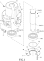
FIG. 1 is a perspective, exploded view of a bearing assembly for a motor according to a first embodiment of the invention. -
FIG. 2 is a cross sectional, assembled view of the bearing assembly for the motor according to the first embodiment of the invention. -
FIG. 3 shows the bearing assembly ofFIG. 2 which further includes a rubber ring coupled with each outer race of a bearing of the bearing assembly. -
FIG. 4 is a cross sectional view of the bearing assembly for the motor taken along line 4-4 inFIG. 2 . -
FIG. 5 is a partially enlarged view ofFIG. 2 before a cover is assembled. -
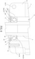
FIG. 6 is a partially enlarged view ofFIG. 2 after the cover is assembled. -
FIG. 7 is a cross sectional view of a motor including the bearing assembly of the first embodiment of the invention. -
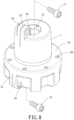
FIG. 8 is a perspective view of a bearing assembly for a motor according to a second embodiment of the invention. -
FIG. 9 is a perspective view of a bearing assembly for a motor according to a third embodiment of the invention. -
FIG. 10 is a perspective view of a bearing assembly for a motor according to a fourth embodiment of the invention. -
FIG. 11 is a perspective view of a bearing assembly for a motor according to a fifth embodiment of the invention. -
FIG. 12 is a perspective view of a bearing assembly for a motor according to a sixth embodiment of the invention. -
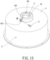
FIG. 13 is a perspective view of a bearing assembly for a motor according to a seventh embodiment of the invention. -
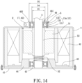
FIG. 14 is a cross sectional view of an assembled motor including a bearing assembly according to an eighth embodiment of the invention. -
FIG. 15 is perspective view of a bearing assembly for a motor according to a ninth embodiment of the invention. - In the various figures of the drawings, the same numerals designate the same or similar parts. Furthermore, when the terms "first", "second", "inner", "outer", "top", "bottom", "axial", "radial" and similar terms are used hereinafter, it should be understood that these terms have reference only to the structure shown in the drawings as it would appear to a person viewing the drawings, and are utilized only to facilitate describing the invention.
-
FIG. 1 shows a bearing assembly for a motor according to a first embodiment of the invention. The bearing assembly includes abearing seat 1 and ashaft 2 extending through thebearing seat 1. - Referring to
FIGS. 1 and2 , the bearingseat 1 includes a chamber S, anassembly hole 11 and ashaft hole 12 which are intercommunicating with each other. Theassembly hole 11 and theshaft hole 12 are located at two ends of thebearing seat 1, respectively. Thus, at least onebearing 13 can be disposed into the chamber S via theassembly hole 11. In this embodiment, there are twobearings 13 disposed in the chamber S, including anupper bearing 13a and alower bearing 13b. Each of theupper bearing 13a and thelower bearing 13b includes aninner race 131, anouter race 132 and a plurality ofballs 133. The plurality ofballs 133 is disposed between theinner race 131 and theouter race 132 to permit theinner race 131 and theouter race 132 to rotate relatively to each other. Theinner race 131 has an outer diameter D1 and theouter race 132 has an outer diameter D2. - Referring to
FIG. 3 , theouter race 132 further includes anouter wall 132a fitted with arubber ring 134. When thebearing 13 is disposed in the chamber S, therubber ring 134 is located between theouter race 132 and an inner wall of thebearing seat 1 to provide a vibration reduction effect. Therubber ring 134 is made of a flexible material such as rubber or silicon. Therubber ring 134 is in an "L" shape and is fit around theouter wall 132a of theouter race 132, as is shown with theupper bearing 13a inFIG. 3 . Alternatively, therubber ring 134 is in the form of a sleeve fit around theouter wall 132a of theouter race 132, as is shown with thelower bearing 13b inFIG. 3 . - Referring to
FIGS. 1 and2 , the bearingseat 1 further includes a plurality of engagingholes 14 on one end face of thebearing seat 1 where theassembly hole 11 is. Each of the plurality of engagingholes 14 can be engaged with afastener 32. Thebearing seat 1 further includes aslit 15 which is adjustable and preferably radially aligned with thebearing 13. Theslit 15 extends through thebearing seat 1 and intercommunicates with the chamber S and theassembly hole 11. Thebearing seat 1 has a horizontal through-hole 16 extending through theslit 15 and radially aligned with thebearing 13. A positioningmember 17 extends through the horizontal through-hole 16 to adjust theslit 15 in a size as required. The positioningmember 17 includes a screw and a nut. Alternatively, the horizontal through-hole 16 is provided with inner threads. In this regard, the positioningmember 17 is provided with outer threads and threaded through the inner threads of the horizontal through-hole 16, thereby adjusting the size of theslit 15. Accordingly, the bearingseat 1 can firmly clamp thebearing 13. - Referring to
FIGS. 1 and2 , theshaft 2 extends through the chamber S of thebearing seat 1. Two ends of theshaft 2 extend out of theassembly hole 11 and theshaft hole 12 of thebearing seat 1, respectively. To couple theshaft 2 with thebearing seat 1 without relative rotation, theshaft 2 includes at least oneabutment portion 21. Theinner race 131 of thebearing 13 abuts theabutment portion 21. In this embodiment, theshaft 2 includes anexpansion portion 20. Theexpansion portion 20 has an end forming anupper abutment portion 21a and another end forming alower abutment portion 21b. Furthermore, the abutment portion 21(s) can be formed in an integral or mold-injecting manner or is press fit with a sleeve to form a diameter difference between the sleeve and theshaft 2. - Referring to
FIGS. 1 and2 , the bearing assembly for the motor according to the first embodiment of the invention further may include acover 3 having a plurality of through-holes 31 and a plurality offasteners 32. Each of the plurality of through-holes 31 is aligned with a respectiveengaging hole 14. Each of the plurality offasteners 32 can extend through a respective through-hole 31 and a respectiveengaging hole 14. Thefastener 32 preferably couples with the engaginghole 14 by threaded engagement to fix thecover 3 to the end of thebearing seat 1 where theassembly hole 11 is. Thecover 3 further includes acentral hole 33. Anannular lip 34 is provided at an edge of thecentral hole 33 and protrudes from the face of thecover 3 facing thebearing seat 1. Theannular lip 34 includes a diameter D3 larger than the outer diameter D1 of theinner race 131 and smaller than the outer diameter D2 of theouter race 132. - Referring to
FIGS. 1 and2 , anelastic member 35 may be disposed between theannular lip 34 and theouter race 132. Theelastic member 35 is preferably disposed on the outer periphery of theannular lip 34 and abuts theouter race 132. Therefore, theelastic member 35 can apply pressure to theouter race 132. Theelastic member 35 can be a conventional rubber ring, a spring or a spring washer. - Referring to
FIGS. 2 ,4 and5 , theshaft 2 extends through thebearing seat 1 in a manner that the two ends of theshaft 2 extend out of theassembly hole 11 and theshaft hole 12 of thebearing seat 1, respectively. Theinner races 131 of thebearings 13 are securely coupled with theshaft 2, and theouter races 132 of thebearings 13 are securely coupled with an inner periphery of thebearing seat 1 delimiting the chamber S. Thecover 3 is fixed to the end of thebearing seat 1 where theassembly hole 11 is. Theinner race 131 of theupper bearing 13a abuts theupper abutment portion 21a of theshaft 2, and theouter race 132 of theupper bearing 13a abuts thebearing seat 1. Theinner race 131 of thelower bearing 13b abuts thelower abutment portion 21b of theshaft 2, and theelastic member 35 abuts theouter race 132 of thelower bearing 13b. Therefore, thebearings 13 are coupled with theshaft 2. In addition, by extending the positioningmember 17 through the horizontal through-hole 16, the tops of theinner race 131 and theouter race 132 are aligned with each other and the bottoms of theinner race 131 and theouter race 132 are aligned with each other. Thus, the plurality ofballs 133 can be firmly coupled with theinner race 131 and theouter race 132. - Referring to
FIG. 6 , after the motor is used for a long time, gaps are formed between theballs 133 and theinner race 131 and theouter race 132 due to the friction therebetween. In this situation, the positioningmember 17 can be loosened. Since theelastic member 35 surrounds theannular lip 34 and abuts theouter race 132, the pressure that theouter race 132 exerts on theinner race 131 can be adjusted to reduce the distance between thecover 3 and the top of thebearing seat 1. As a result, theouter race 132 is misaligned with theinner race 131, causing misalignment between the tops of theinner race 131 and theouter race 132 and between the bottoms of theinner race 131 and theouter race 132. This enables the plurality ofballs 133 to be firmly coupled with theinner race 131 and theouter race 132 again. At this time, the positioningmember 17 can be tightened to reduce theslit 15 of thebearing seat 1, such that thebearing seat 1 can properly clamp thebearing 13. - Referring to
FIG. 7 , the bearingseat 1 further includes anengagement face 10 having a plurality of positioning holes 101. Afastener 8 extends into arespective positioning hole 101 to couple ahousing 4 of a motor with thebearing seat 1. Thehousing 4 accommodates astator 42, acircuit board 43, and apermanent magnet 7 mounted to an inner periphery of thehousing 4. Thehousing 4 and thebearing seat 1 can rotate relatively to thestator 42. As the motor is used for a long time where gaps are formed between theballs 133 and theinner race 131 and theouter race 132 due to the friction therebetween, the positioningmember 17 can be loosened for theelastic member 35 to adjust the pressure theouter race 132 exerts on theinner race 131. In this regard, theouter race 132 is misaligned with theinner race 131 to permit theballs 133 to firmly connect to theinner race 131 and theouter race 132 again. Then, the positioningmember 17 is tightened up to permit thebearing seat 1 to properly clamp thebearing 13. Thus, thehousing 4 and thebearing seat 1 can smoothly rotate relatively to thestator 42 to reduce the noise in rotation and to increase the lifespan of thebearings 13. -
FIG. 8 shows a bearing assembly for a motor according to a second embodiment of the invention. As compared with the first embodiment, the bearingseat 1 in the second embodiment further includes aprotrusion 18 protruding from a top of thebearing seat 1 where theshaft hole 12 is. Theprotrusion 18 also includes a slit 15' which is adjustable. The slit 15' extends through theprotrusion 18 and intercommunicates with theshaft hole 12. Theprotrusion 18 also includes a horizontal through-hole 16' extending through theprotrusion 18. A positioningmember 17 can extend through the horizontal through-hole 16'. The positioningmember 17 may be a screw and a nut. Alternatively, the horizontal through-hole 16' includes inner threads such that the threadedpositioning member 17 can be directly screwed through the horizontal through-hole 16' to adjust the slit 15'. In this regard, since thebearing seat 1 includes twoslits 15 and 15' and two horizontal through-holes 16 and 16', each positioningmember 17 can be operated to adjust acorresponding slit 15 or 15' in a size as required when the motor is used for a long time where gaps are formed between theballs 133 and theinner race 131 and theouter race 132 due to the friction therebetween. This permits thebearing seat 1 to firmly clamp thebearing 13 as shown inFIG. 2 . -
FIG. 9 shows a bearing assembly for a motor according to a third embodiment of the invention. As compared with the second embodiment, theslit 15 in this embodiment intercommunicates with the slit 15' of theprotrusion 18. A positioningmember 17 can extend through the horizontal through-hole 16, and another positioningmember 17 can also extend through the horizontal through-hole 16' of theprotrusion 18. In this arrangement, as the motor is used for a long time where gaps are formed between theballs 133 and theinner race 131 and theouter race 132 due to the friction therebetween, each positioningmember 17 can be operated to adjust acorresponding slit 15 or 15' in a size as required. Advantageously, the bearingseat 1 is able to clamp thebearing 13 more securely as is shown inFIG 2 . -
FIG. 10 shows a bearing assembly for a motor according to a fourth embodiment of the invention. As compared with the second embodiment, the bearingseat 1 in the fourth embodiment further includes aprotrusion 18 protruding from an outer periphery of thebearing seat 1 at an end of theshaft hole 12. Theprotrusion 18 also includes a slit 15' which is adjustable. The slit 15' extends through theprotrusion 18 and intercommunicates with theshaft hole 12. Theprotrusion 18 includes a horizontal through-hole 16' extending through theprotrusion 18. A positioningmember 17 can extend through the horizontal through-hole 16'. The positioningmember 17 may be a screw and a nut. Alternatively, the horizontal through-hole 16' includes inner threads such that the threadedpositioning member 17 can be directly screwed through the horizontal through-hole 16' to adjust the slit 15' in a size as required. In this regard, since thebearing seat 1 includes twoslits 15 and 15' and two horizontal through-holes 16 and 16', each positioningmember 17 can be operated to adjust acorresponding slit 15 or 15' in a size as required when the motor is used for a long time where gaps are formed between theballs 133 and theinner race 131 and theouter race 132 due to the friction therebetween. This permits thebearing seat 1 to firmly clamp thebearing 13 as shown inFIG. 2 . -
FIG. 11 shows a bearing assembly for a motor according to a fifth embodiment of the invention. As compared with the fourth embodiment, the slit 15' is formed on an end of thebearing seat 1 where theshaft hole 12 is. The slit 15' extends through thebearing seat 1 from the inner periphery to the outer periphery thereof and intercommunicates with theshaft hole 12. The horizontal through-hole 16' extends through the slit 15'. A positioningmember 17 can extend through the horizontal through-hole 16'. The positioningmember 17 may be a screw and a nut. Alternatively, the horizontal through-hole 16' includes inner threads such that the threadedpositioning member 17 can be directly screwed through the horizontal through-hole 16' to adjust the slit 15' in a size as required. In this regard, each positioningmember 17 can be operated to adjust theslit 15 in a size as required when the motor is used for a long time where gaps are formed between theballs 133 and theinner race 131 and theouter race 132 due to the friction therebetween. This permits thebearing seat 1 to firmly clamp thebearing 13 as shown inFIG. 2 . -
FIG. 12 shows a bearing assembly for a motor according to a sixth embodiment of the invention. As compared with the fifth embodiment, the bearingseat 1 includes adisc 19 at an end of thebearing seat 1 where theassembly hole 11 is. Theslit 15 extends through thedisc 19 and towards another end of thebearing seat 1 where theshaft hole 12 is. The horizontal through-hole 16 extends through theslit 15. Thedisc 19 includes acutoff portion 191 intercommunicating with the horizontal through-hole 16 to permit the positioningmember 17 to extend into the horizontal through-hole 16. In this arrangement, theslit 15 can be adjusted in a size as required for thebearing seat 1 to firmly clamp thebearing 13 as is shown inFIG. 2 . -
FIGS. 13 and14 show a motor including the bearing assembly according to an embodiment of the invention. The motor includes ahousing 4 having a compartment R. The compartment R has an opening coupled with abottom plate 41. Thebottom plate 41 is located at an end of thehousing 4. Thehousing 4 includes astator 42 and acircuit board 43. Thebottom plate 41 includes aseat 44 that can support ashaft 5 that rotates. Asupport 45 is preferably disposed between theshaft 5 and theseat 44. Thesupport 45 may be a conventional self-lubricating bearing, an oil bearing, a ball bearing or the like that provides theshaft 5 with stable rotation. Thesupport 45 is a ball bearing in this embodiment. Thehousing 4 further includes a bearingseat 46 having ashaft hole 461. Theshaft hole 461 has a diameter D4. An end of theshaft 5 extends through theshaft hole 461. Abearing 13 is received in the bearingseat 46 and includes aninner race 131, anouter race 132 and a plurality ofballs 133. Theinner race 131 has an outer diameter D1 and theouter race 132 has an outer diameter D2. The diameter D4 of theshaft hole 461 is larger than the outer diameter D1 of theinner race 131 but is smaller than the outer diameter D2 of theouter race 132, permitting the top of the bearingseat 46 to abut theouter race 132. The bearingseat 46 includes aslit 462 and a horizontal through-hole 463. Theslit 462 is adjustable. A positioningmember 17 can extend through the horizontal through-hole 463 to adjust theslit 462 in a size as required. - Referring to
FIGS. 13 and14 , theshaft 5 has an end that abuts thesupport 45 and rotates thereupon. Theshaft 5 is coupled with arotor 51 and anelastic element 52. Therotor 51 rotates relatively to thestator 42. Apositioning ring 53 is preferably disposed between therotor 51 and theshaft 5, such that therotor 51 can be coupled with theshaft 5. Theelastic element 52 has an end connected to thesupport 45, as well as another end connected to an end of thepositioning ring 53. Another end of thepositioning ring 53 is connected to the otherinner race 131 of theother bearing 13. Theelastic element 52 can apply pressure to theinner race 131, thereby securely coupling the plurality ofballs 133 with theinner race 131 and theouter race 132. - Referring to
FIGS. 13 and14 again, as the motor is used for a long time where gaps are formed between theballs 133 and theinner race 131 and theouter race 132 due to the friction therebetween, the positioningmember 17 can be loosened. Due to the arrangement of theelastic element 52, theelastic element 52 pushes thepositioning ring 53 and theshaft 5 upwards in an axial direction by applying pressure thereto. Accordingly, theinner race 131 moves relatively to theouter race 132. This permits the plurality ofballs 133 to securely couple with theinner race 131 and theouter race 132 again. In this regard, the positioningmember 17 can be tightened up to reduce theslit 15 of the bearingseat 46, permitting the bearingseat 46 to firmly clamp thebearing 13. In this arrangement, theshaft 5 can smoothly rotate relatively to the bearingseat 46 again, thus reducing the noise during the operation and increasing the lifespan of thebearing 13. -
FIGS. 14 and15 show a motor including the bearing assembly according to another embodiment of the invention. In this embodiment. Theslit 462 can be adjusted by apositioning ring 6. Thepositioning ring 6 includes ahole 61, aslit 62 and a horizontal through-hole 63. Thepositioning ring 6 is fit around the bearingseat 46. Theslit 62 extends through thepositioning ring 6 from an inner periphery delimiting thehole 61 to an outer periphery thereof. The horizontal through-hole 63 extends through theslit 62. A positioningmember 17 can extend through the horizontal through-hole 63 to adjust theslit 62 in a size as required. Therefore, via the use of thepositioning ring 6, the bearing 13 can be rotation and increasing the lifespan of thebearing 13. - In summary, via the arrangement of the slit, the bearing assembly according to the invention can misalign the inner race with the outer race by applying pressure to the inner race or the outer race when gaps are formed between the balls and the inner race and the outer race due to the friction therebetween. In this regard, a positioning member can be tightened up to adjust the slit in a size as required, such that the balls can be securely coupled with the inner race and the outer race. Therefore, the motor including the bearing assembly can achieve the advantages of reducing the noise in rotation and increasing the lifespan of the bearings.
Claims (11)
- An outer-rotor motor comprising:a bearing seat (1) including a chamber (S), an engagement face (10), an assembly hole (11) and a shaft hole (12), wherein the assembly hole (11) and the shaft hole (12) intercommunicate with the chamber (S);a stator (42);at least one bearing (13) received in the chamber (S); anda shaft (2) extending through the shaft hole (12) and the at least one bearing (13),wherein the bearing seat (1) has a slit (15, 15') which is adjustable, wherein the shaft (2) includes at least one abutment portion (21), and wherein the at least one bearing (13) abuts the at least one abutment portion (21),wherein the outer-rotor motor further comprising a rotor engaged with the engagement face (10), wherein the rotor includes a housing (4) accommodating the stator (42),the outer-rotor motor further comprising a cover (3) coupled with the bearing seat (1),wherein the at least one bearing (13) includes a first bearing (13) relatively distant to the cover (3) and a second bearing (13) relatively adjacent to the cover (3), wherein each of the first and second bearings (13) includes an inner race (131) and an outer race (132) and a plurality of balls (133), and wherein an elastic member (35) is disposed between the cover (3) and the outer race (132) of the second bearing (13),wherein the bearing seat (1) has a horizontal through-hole (16, 16') extending through the slit (15, 15'), wherein a positioning member (17) extends through the horizontal through-hole (16, 16') to adjust the slit (15, 15'), wherein the horizontal through-hole (16) is radially aligned with one of the at least one bearing (13),wherein the positioning member (17) is configured to be loosened for the elastic member (35) to adjust the pressure the outer race (132) exerts on the inner race (131), and the outer race (132) is misaligned with the inner race (131) to permit the balls (133) to firmly connect to the inner race (131) and the outer race (132), and the positioning member (17) is configured to be tightened up to permit the bearing seat (1) to properly clamp the at least one bearing (13).
- The outer-rotor motor as claimed in claim 1, characterized in that the outer race (132) includes an outer wall (132a) fitted with a rubber ring (134).
- The outer-rotor motor as claimed in claim 1, characterized in that the cover (3) includes a central hole (33), wherein an annular lip (34) is provided at an edge of the central hole (33) and protrudes from a face of the cover (3) facing the bearing seat (1), wherein the inner race (131) has an outer diameter (D1) and the outer race (132) has an outer diameter (D2), wherein the annular lip (34) includes a diameter (D3) larger than the outer diameter (D1) of the inner race (131) and smaller than the outer diameter (D2) of the outer race (132), and wherein the elastic member (35) surrounds the annular lip (34) and abuts the outer race (132).
- The outer-rotor motor as claimed in claim 1, characterized in that the bearing seat (1) includes a plurality of engaging holes (14) on one end face of the bearing seat (1) where the assembly hole (11) is, wherein the cover (3) has a plurality of through-holes (31), wherein a plurality of fasteners (32) respectively extends through the plurality of through-holes (31), wherein the bearing seat (1) includes a disc (19) at an end of the bearing seat (1) where the assembly hole (11) is, wherein the slit (15) extends through the disc (19) and towards another end of the bearing seat (1) where the shaft hole (12) is, and wherein the disc (19) includes a cutoff portion (191) intercommunicating with the horizontal through-hole (16).
- The outer-rotor motor as claimed in claim 1, characterized in that the slit (15) is formed on an end of the bearing seat (1) where the assembly hole (11) is, and wherein the slit (15) is radially aligned with one of the at least one bearing (13).
- The outer-rotor motor as claimed in claim 1, characterized in that the slit (15') extends through the bearing seat (1) from an inner periphery to an outer periphery of the bearing seat (1) and intercommunicates with the chamber (S).
- The outer-rotor motor as claimed in claim 1, characterized in that the elastic member (35) is a rubber ring, a spring or a spring washer.
- The outer-rotor motor as claimed in claim 1, characterized in that the shaft (2) includes an expansion portion (20), wherein the expansion portion (20) has an end forming a first abutment portion (21a) and another end forming a second abutment portion (21b), wherein the inner race (131) of the first bearing (13) abuts the first abutment portion (21a), wherein the outer race (132) of the first bearing (13) abuts an inner periphery of the bearing seat (1) delimiting the chamber (S), wherein the inner race (131) of the second bearing (13) abuts the second abutment portion (21b), wherein the outer race (132) of the second bearing (13) abuts the elastic member (35), wherein the bearing seat (1) further includes a protrusion (18) protruding from a top of the bearing seat (1) where the shaft hole (12) is, wherein the protrusion (18) includes the slit (15') extending through the protrusion (18) and intercommunicating with the shaft hole (12), wherein the protrusion (18) includes the horizontal through-hole (16') extending through the protrusion (18), and wherein the positioning member (17) extends through the horizontal through-hole (16') of the protrusion (18) to adjust the slit (15').
- The outer-rotor motor as claimed in claim 8, characterized in that the horizontal through-hole (16') of the protrusion (18) is provided with inner threads, and wherein the positioning member (17) is provided with outer threads.
- The outer-rotor motor as claimed in claim 8, characterized in that the slit (15') of the protrusion (18) intercommunicates with the slit (15) of the bearing seat (1).
- The outer-rotor motor as claimed in claim 1, characterized in that the slit (15') is formed on an end of the bearing seat (1) where the shaft hole (12) is and intercommunicates with the shaft hole (12).
Applications Claiming Priority (1)
| Application Number | Priority Date | Filing Date | Title |
|---|---|---|---|
| TW106135117A TWI632305B (en) | 2017-10-13 | 2017-10-13 | Bearing set and a motor including the same |
Publications (2)
| Publication Number | Publication Date |
|---|---|
| EP3470698A1 EP3470698A1 (en) | 2019-04-17 |
| EP3470698B1 true EP3470698B1 (en) | 2023-04-19 |
Family
ID=63959868
Family Applications (1)
| Application Number | Title | Priority Date | Filing Date |
|---|---|---|---|
| EP18195140.1A Active EP3470698B1 (en) | 2017-10-13 | 2018-09-18 | Outer-rotor motor |
Country Status (4)
| Country | Link |
|---|---|
| US (2) | US10763720B2 (en) |
| EP (1) | EP3470698B1 (en) |
| CN (1) | CN109667839A (en) |
| TW (1) | TWI632305B (en) |
Families Citing this family (10)
| Publication number | Priority date | Publication date | Assignee | Title |
|---|---|---|---|---|
| CN109565208B (en) * | 2016-08-05 | 2021-06-08 | 日本电产株式会社 | motor |
| TWI632305B (en) * | 2017-10-13 | 2018-08-11 | 建準電機工業股份有限公司 | Bearing set and a motor including the same |
| TWI679830B (en) * | 2019-01-04 | 2019-12-11 | 建準電機工業股份有限公司 | Motor and ceiling fan including the same |
| EP4146950B1 (en) * | 2020-05-06 | 2024-03-06 | Parker-Hannifin Corporation | Motor bearing preloading system with plastic endbells |
| JP2022055432A (en) * | 2020-09-29 | 2022-04-08 | 株式会社ジェイテクト | Bearing device and rotating device using bearing device |
| EP4441383A1 (en) * | 2021-12-02 | 2024-10-09 | Pierburg Pump Technology GmbH | Bearing seat arrangement |
| TWI792804B (en) * | 2021-12-23 | 2023-02-11 | 豪力輝工業股份有限公司 | Drive shaft bearing seat mounting device |
| IL320258A (en) * | 2022-10-14 | 2025-06-01 | Novanta Corp | Systems and methods for providing vibration reduction in galvanometers |
| WO2024178818A1 (en) * | 2023-02-27 | 2024-09-06 | 林维勇 | Motor bearing structure convenient to position and assemble and cooling fan |
| CN116480694A (en) * | 2023-04-14 | 2023-07-25 | 机械工业第九设计研究院股份有限公司 | Shaft seal structure is worn in drying chamber transportation |
Citations (1)
| Publication number | Priority date | Publication date | Assignee | Title |
|---|---|---|---|---|
| WO2004048791A1 (en) * | 2002-11-26 | 2004-06-10 | Ebm-Papst St. Georgen Gmbh & Co. Kg | External rotor motor and method for assembling such a motor |
Family Cites Families (22)
| Publication number | Priority date | Publication date | Assignee | Title |
|---|---|---|---|---|
| SE364520B (en) * | 1972-06-29 | 1974-02-25 | Aga Ab | |
| JPS4955602U (en) * | 1972-08-24 | 1974-05-16 | ||
| JPS5536666A (en) * | 1978-09-06 | 1980-03-14 | Ntn Toyo Bearing Co Ltd | Bearing |
| US4386812A (en) * | 1981-07-06 | 1983-06-07 | Marathon Electric Manufacturing Corp. | Bearing lock for a dynamoelectric machine |
| US4854750A (en) * | 1988-10-06 | 1989-08-08 | Lavin Aaron M | Zero clearance bearing system |
| US5439299A (en) * | 1995-01-13 | 1995-08-08 | Havens; Dale I. | Self-adjusting bearing support |
| JPH11356001A (en) * | 1998-06-09 | 1999-12-24 | Aichi Electric Co Ltd | Motor bearing device |
| US6584887B1 (en) * | 1998-11-03 | 2003-07-01 | Tol-O-Matic, Inc. | Linear motor device |
| US6485023B2 (en) * | 2000-05-04 | 2002-11-26 | Flowserve Management Company | Split mechanical face seal |
| DE10195939D2 (en) * | 2001-02-01 | 2004-01-15 | Luk Lamellen & Kupplungsbau | bearing arrangement |
| DE10252622A1 (en) * | 2002-11-11 | 2004-05-27 | Continental Teves Ag & Co. Ohg | Motor pump aggregate for motor vehicle braking system has motor and pump that comprises shaft that is driven by motor and bearings of end of shaft are arranged in reception body that is provided with valves and connection channels |
| JP2007174789A (en) * | 2005-12-21 | 2007-07-05 | Nsk Ltd | Motor with position adjustment mechanism |
| ITTO20060682A1 (en) * | 2006-09-26 | 2008-03-27 | Skf Ab | SUPPORT UNIT FOR GOKART SEMI-AXIS. |
| JP2009095111A (en) * | 2007-10-05 | 2009-04-30 | Nsk Ltd | Motor and electric power steering device |
| DE102010054905A1 (en) * | 2010-12-17 | 2012-06-21 | Schaeffler Technologies Gmbh & Co. Kg | Bearing unit for a turbocharger |
| KR101930330B1 (en) * | 2012-06-15 | 2018-12-18 | 엘지이노텍 주식회사 | Motor |
| CN203607977U (en) * | 2013-11-22 | 2014-05-21 | 江苏远东电机制造有限公司 | Conveniently adjusting structure for motor bearing clearance |
| TWI556552B (en) * | 2014-10-16 | 2016-11-01 | 建準電機工業股份有限公司 | Motor |
| CN205624866U (en) * | 2016-05-19 | 2016-10-12 | 浙江永强集团股份有限公司 | Automatic with parachute kit of non -automatic combination structure that opens and shuts |
| TWI602385B (en) * | 2016-09-01 | 2017-10-11 | 建準電機工業股份有限公司 | Inner-rotor type motor and stator thereof |
| US10666124B2 (en) * | 2017-02-09 | 2020-05-26 | Johnson Electric International AG | Linear stepper motor and valve utilizing the same |
| TWI632305B (en) * | 2017-10-13 | 2018-08-11 | 建準電機工業股份有限公司 | Bearing set and a motor including the same |
-
2017
- 2017-10-13 TW TW106135117A patent/TWI632305B/en active
- 2017-10-30 CN CN201711034888.0A patent/CN109667839A/en active Pending
-
2018
- 2018-08-27 US US16/112,947 patent/US10763720B2/en active Active
- 2018-09-18 EP EP18195140.1A patent/EP3470698B1/en active Active
-
2020
- 2020-05-21 US US16/880,331 patent/US20200280237A1/en not_active Abandoned
Patent Citations (1)
| Publication number | Priority date | Publication date | Assignee | Title |
|---|---|---|---|---|
| WO2004048791A1 (en) * | 2002-11-26 | 2004-06-10 | Ebm-Papst St. Georgen Gmbh & Co. Kg | External rotor motor and method for assembling such a motor |
Also Published As
| Publication number | Publication date |
|---|---|
| US20200280237A1 (en) | 2020-09-03 |
| EP3470698A1 (en) | 2019-04-17 |
| CN109667839A (en) | 2019-04-23 |
| TW201915352A (en) | 2019-04-16 |
| US20190115799A1 (en) | 2019-04-18 |
| US10763720B2 (en) | 2020-09-01 |
| TWI632305B (en) | 2018-08-11 |
Similar Documents
| Publication | Publication Date | Title |
|---|---|---|
| US10763720B2 (en) | Bearing assembly and motor including the same | |
| JP5834090B2 (en) | Especially the electric machine of the pump unit | |
| US9702403B2 (en) | Bearing assembly | |
| US5562347A (en) | Structure for a brushless direct current fan | |
| US20140154072A1 (en) | Support for rolling bearings | |
| US10865871B2 (en) | Arrangement for axially bracing a CVT-fixed bearing from outside a transmission housing | |
| US11898607B2 (en) | Non-locating bearing assembly | |
| KR20140019282A (en) | Connecting structure for mechanical connection of a first housing to a second housing | |
| CN101382147A (en) | Radiator fan and modularized bearing system thereof | |
| US11916461B2 (en) | Assembly for supporting an electric motor, notably in a motor vehicle heating, ventilation and/or air conditioning device | |
| US11892034B2 (en) | Non-locating bearing assembly | |
| KR20210075937A (en) | A Fan Motor | |
| US11287028B2 (en) | Assembly for securing the axial position of a sun gear of a planetary gearing stage on a rotor shaft of an electrical machine, and use of such an assembly | |
| US20220389958A1 (en) | Non-locating bearing assembly | |
| CN112470371A (en) | Electric motor | |
| KR101408443B1 (en) | Electrical internal combustion engine adjusting arrangement | |
| US20150219149A1 (en) | Bearing assembly for an electric motor with an axially preloaded ball bearing | |
| WO2006117515A8 (en) | Vacuum pump | |
| EP2685606B1 (en) | Motor's stator unit | |
| US20060291758A1 (en) | Shaft assembly for motor | |
| JP5467253B2 (en) | Ball screw shaft integrated step motor bearing structure | |
| JP4587904B2 (en) | Power transmission device | |
| CN103836153A (en) | Pulley device, turning machine fitted with such a device and method of mounting such a device on a turning machine | |
| US7021831B2 (en) | Zero radial and axial clearance bearing assembly | |
| KR101716554B1 (en) | Auto-tensioner |
Legal Events
| Date | Code | Title | Description |
|---|---|---|---|
| PUAI | Public reference made under article 153(3) epc to a published international application that has entered the european phase |
Free format text: ORIGINAL CODE: 0009012 |
|
| STAA | Information on the status of an ep patent application or granted ep patent |
Free format text: STATUS: THE APPLICATION HAS BEEN PUBLISHED |
|
| AK | Designated contracting states |
Kind code of ref document: A1 Designated state(s): AL AT BE BG CH CY CZ DE DK EE ES FI FR GB GR HR HU IE IS IT LI LT LU LV MC MK MT NL NO PL PT RO RS SE SI SK SM TR |
|
| AX | Request for extension of the european patent |
Extension state: BA ME |
|
| STAA | Information on the status of an ep patent application or granted ep patent |
Free format text: STATUS: REQUEST FOR EXAMINATION WAS MADE |
|
| 17P | Request for examination filed |
Effective date: 20190503 |
|
| RBV | Designated contracting states (corrected) |
Designated state(s): AL AT BE BG CH CY CZ DE DK EE ES FI FR GB GR HR HU IE IS IT LI LT LU LV MC MK MT NL NO PL PT RO RS SE SI SK SM TR |
|
| STAA | Information on the status of an ep patent application or granted ep patent |
Free format text: STATUS: EXAMINATION IS IN PROGRESS |
|
| 17Q | First examination report despatched |
Effective date: 20220628 |
|
| GRAP | Despatch of communication of intention to grant a patent |
Free format text: ORIGINAL CODE: EPIDOSNIGR1 |
|
| STAA | Information on the status of an ep patent application or granted ep patent |
Free format text: STATUS: GRANT OF PATENT IS INTENDED |
|
| INTG | Intention to grant announced |
Effective date: 20221202 |
|
| GRAS | Grant fee paid |
Free format text: ORIGINAL CODE: EPIDOSNIGR3 |
|
| GRAA | (expected) grant |
Free format text: ORIGINAL CODE: 0009210 |
|
| STAA | Information on the status of an ep patent application or granted ep patent |
Free format text: STATUS: THE PATENT HAS BEEN GRANTED |
|
| AK | Designated contracting states |
Kind code of ref document: B1 Designated state(s): AL AT BE BG CH CY CZ DE DK EE ES FI FR GB GR HR HU IE IS IT LI LT LU LV MC MK MT NL NO PL PT RO RS SE SI SK SM TR |
|
| REG | Reference to a national code |
Ref country code: GB Ref legal event code: FG4D |
|
| REG | Reference to a national code |
Ref country code: CH Ref legal event code: EP |
|
| REG | Reference to a national code |
Ref country code: DE Ref legal event code: R096 Ref document number: 602018048511 Country of ref document: DE |
|
| REG | Reference to a national code |
Ref country code: IE Ref legal event code: FG4D |
|
| REG | Reference to a national code |
Ref country code: AT Ref legal event code: REF Ref document number: 1561391 Country of ref document: AT Kind code of ref document: T Effective date: 20230515 |
|
| REG | Reference to a national code |
Ref country code: LT Ref legal event code: MG9D |
|
| REG | Reference to a national code |
Ref country code: NL Ref legal event code: MP Effective date: 20230419 |
|
| REG | Reference to a national code |
Ref country code: AT Ref legal event code: MK05 Ref document number: 1561391 Country of ref document: AT Kind code of ref document: T Effective date: 20230419 |
|
| PG25 | Lapsed in a contracting state [announced via postgrant information from national office to epo] |
Ref country code: NL Free format text: LAPSE BECAUSE OF FAILURE TO SUBMIT A TRANSLATION OF THE DESCRIPTION OR TO PAY THE FEE WITHIN THE PRESCRIBED TIME-LIMIT Effective date: 20230419 |
|
| PG25 | Lapsed in a contracting state [announced via postgrant information from national office to epo] |
Ref country code: SE Free format text: LAPSE BECAUSE OF FAILURE TO SUBMIT A TRANSLATION OF THE DESCRIPTION OR TO PAY THE FEE WITHIN THE PRESCRIBED TIME-LIMIT Effective date: 20230419 Ref country code: PT Free format text: LAPSE BECAUSE OF FAILURE TO SUBMIT A TRANSLATION OF THE DESCRIPTION OR TO PAY THE FEE WITHIN THE PRESCRIBED TIME-LIMIT Effective date: 20230821 Ref country code: NO Free format text: LAPSE BECAUSE OF FAILURE TO SUBMIT A TRANSLATION OF THE DESCRIPTION OR TO PAY THE FEE WITHIN THE PRESCRIBED TIME-LIMIT Effective date: 20230719 Ref country code: ES Free format text: LAPSE BECAUSE OF FAILURE TO SUBMIT A TRANSLATION OF THE DESCRIPTION OR TO PAY THE FEE WITHIN THE PRESCRIBED TIME-LIMIT Effective date: 20230419 Ref country code: AT Free format text: LAPSE BECAUSE OF FAILURE TO SUBMIT A TRANSLATION OF THE DESCRIPTION OR TO PAY THE FEE WITHIN THE PRESCRIBED TIME-LIMIT Effective date: 20230419 |
|
| PG25 | Lapsed in a contracting state [announced via postgrant information from national office to epo] |
Ref country code: RS Free format text: LAPSE BECAUSE OF FAILURE TO SUBMIT A TRANSLATION OF THE DESCRIPTION OR TO PAY THE FEE WITHIN THE PRESCRIBED TIME-LIMIT Effective date: 20230419 Ref country code: PL Free format text: LAPSE BECAUSE OF FAILURE TO SUBMIT A TRANSLATION OF THE DESCRIPTION OR TO PAY THE FEE WITHIN THE PRESCRIBED TIME-LIMIT Effective date: 20230419 Ref country code: LV Free format text: LAPSE BECAUSE OF FAILURE TO SUBMIT A TRANSLATION OF THE DESCRIPTION OR TO PAY THE FEE WITHIN THE PRESCRIBED TIME-LIMIT Effective date: 20230419 Ref country code: LT Free format text: LAPSE BECAUSE OF FAILURE TO SUBMIT A TRANSLATION OF THE DESCRIPTION OR TO PAY THE FEE WITHIN THE PRESCRIBED TIME-LIMIT Effective date: 20230419 Ref country code: IS Free format text: LAPSE BECAUSE OF FAILURE TO SUBMIT A TRANSLATION OF THE DESCRIPTION OR TO PAY THE FEE WITHIN THE PRESCRIBED TIME-LIMIT Effective date: 20230819 Ref country code: HR Free format text: LAPSE BECAUSE OF FAILURE TO SUBMIT A TRANSLATION OF THE DESCRIPTION OR TO PAY THE FEE WITHIN THE PRESCRIBED TIME-LIMIT Effective date: 20230419 Ref country code: GR Free format text: LAPSE BECAUSE OF FAILURE TO SUBMIT A TRANSLATION OF THE DESCRIPTION OR TO PAY THE FEE WITHIN THE PRESCRIBED TIME-LIMIT Effective date: 20230720 Ref country code: AL Free format text: LAPSE BECAUSE OF FAILURE TO SUBMIT A TRANSLATION OF THE DESCRIPTION OR TO PAY THE FEE WITHIN THE PRESCRIBED TIME-LIMIT Effective date: 20230419 |
|
| PG25 | Lapsed in a contracting state [announced via postgrant information from national office to epo] |
Ref country code: FI Free format text: LAPSE BECAUSE OF FAILURE TO SUBMIT A TRANSLATION OF THE DESCRIPTION OR TO PAY THE FEE WITHIN THE PRESCRIBED TIME-LIMIT Effective date: 20230419 |
|
| PG25 | Lapsed in a contracting state [announced via postgrant information from national office to epo] |
Ref country code: SK Free format text: LAPSE BECAUSE OF FAILURE TO SUBMIT A TRANSLATION OF THE DESCRIPTION OR TO PAY THE FEE WITHIN THE PRESCRIBED TIME-LIMIT Effective date: 20230419 |
|
| REG | Reference to a national code |
Ref country code: DE Ref legal event code: R097 Ref document number: 602018048511 Country of ref document: DE |
|
| PG25 | Lapsed in a contracting state [announced via postgrant information from national office to epo] |
Ref country code: SM Free format text: LAPSE BECAUSE OF FAILURE TO SUBMIT A TRANSLATION OF THE DESCRIPTION OR TO PAY THE FEE WITHIN THE PRESCRIBED TIME-LIMIT Effective date: 20230419 Ref country code: SK Free format text: LAPSE BECAUSE OF FAILURE TO SUBMIT A TRANSLATION OF THE DESCRIPTION OR TO PAY THE FEE WITHIN THE PRESCRIBED TIME-LIMIT Effective date: 20230419 Ref country code: RO Free format text: LAPSE BECAUSE OF FAILURE TO SUBMIT A TRANSLATION OF THE DESCRIPTION OR TO PAY THE FEE WITHIN THE PRESCRIBED TIME-LIMIT Effective date: 20230419 Ref country code: EE Free format text: LAPSE BECAUSE OF FAILURE TO SUBMIT A TRANSLATION OF THE DESCRIPTION OR TO PAY THE FEE WITHIN THE PRESCRIBED TIME-LIMIT Effective date: 20230419 Ref country code: DK Free format text: LAPSE BECAUSE OF FAILURE TO SUBMIT A TRANSLATION OF THE DESCRIPTION OR TO PAY THE FEE WITHIN THE PRESCRIBED TIME-LIMIT Effective date: 20230419 Ref country code: CZ Free format text: LAPSE BECAUSE OF FAILURE TO SUBMIT A TRANSLATION OF THE DESCRIPTION OR TO PAY THE FEE WITHIN THE PRESCRIBED TIME-LIMIT Effective date: 20230419 |
|
| PLBE | No opposition filed within time limit |
Free format text: ORIGINAL CODE: 0009261 |
|
| STAA | Information on the status of an ep patent application or granted ep patent |
Free format text: STATUS: NO OPPOSITION FILED WITHIN TIME LIMIT |
|
| 26N | No opposition filed |
Effective date: 20240122 |
|
| REG | Reference to a national code |
Ref country code: CH Ref legal event code: PL |
|
| PG25 | Lapsed in a contracting state [announced via postgrant information from national office to epo] |
Ref country code: SI Free format text: LAPSE BECAUSE OF FAILURE TO SUBMIT A TRANSLATION OF THE DESCRIPTION OR TO PAY THE FEE WITHIN THE PRESCRIBED TIME-LIMIT Effective date: 20230419 |
|
| PG25 | Lapsed in a contracting state [announced via postgrant information from national office to epo] |
Ref country code: LU Free format text: LAPSE BECAUSE OF NON-PAYMENT OF DUE FEES Effective date: 20230918 |
|
| REG | Reference to a national code |
Ref country code: BE Ref legal event code: MM Effective date: 20230930 |
|
| PG25 | Lapsed in a contracting state [announced via postgrant information from national office to epo] |
Ref country code: SI Free format text: LAPSE BECAUSE OF FAILURE TO SUBMIT A TRANSLATION OF THE DESCRIPTION OR TO PAY THE FEE WITHIN THE PRESCRIBED TIME-LIMIT Effective date: 20230419 Ref country code: LU Free format text: LAPSE BECAUSE OF NON-PAYMENT OF DUE FEES Effective date: 20230918 Ref country code: IT Free format text: LAPSE BECAUSE OF FAILURE TO SUBMIT A TRANSLATION OF THE DESCRIPTION OR TO PAY THE FEE WITHIN THE PRESCRIBED TIME-LIMIT Effective date: 20230419 Ref country code: MC Free format text: LAPSE BECAUSE OF FAILURE TO SUBMIT A TRANSLATION OF THE DESCRIPTION OR TO PAY THE FEE WITHIN THE PRESCRIBED TIME-LIMIT Effective date: 20230419 |
|
| REG | Reference to a national code |
Ref country code: IE Ref legal event code: MM4A |
|
| PG25 | Lapsed in a contracting state [announced via postgrant information from national office to epo] |
Ref country code: IE Free format text: LAPSE BECAUSE OF NON-PAYMENT OF DUE FEES Effective date: 20230918 |
|
| PG25 | Lapsed in a contracting state [announced via postgrant information from national office to epo] |
Ref country code: CH Free format text: LAPSE BECAUSE OF NON-PAYMENT OF DUE FEES Effective date: 20230930 |
|
| PG25 | Lapsed in a contracting state [announced via postgrant information from national office to epo] |
Ref country code: IE Free format text: LAPSE BECAUSE OF NON-PAYMENT OF DUE FEES Effective date: 20230918 Ref country code: CH Free format text: LAPSE BECAUSE OF NON-PAYMENT OF DUE FEES Effective date: 20230930 |
|
| PG25 | Lapsed in a contracting state [announced via postgrant information from national office to epo] |
Ref country code: BE Free format text: LAPSE BECAUSE OF NON-PAYMENT OF DUE FEES Effective date: 20230930 |
|
| PG25 | Lapsed in a contracting state [announced via postgrant information from national office to epo] |
Ref country code: BG Free format text: LAPSE BECAUSE OF FAILURE TO SUBMIT A TRANSLATION OF THE DESCRIPTION OR TO PAY THE FEE WITHIN THE PRESCRIBED TIME-LIMIT Effective date: 20230419 |
|
| PG25 | Lapsed in a contracting state [announced via postgrant information from national office to epo] |
Ref country code: BG Free format text: LAPSE BECAUSE OF FAILURE TO SUBMIT A TRANSLATION OF THE DESCRIPTION OR TO PAY THE FEE WITHIN THE PRESCRIBED TIME-LIMIT Effective date: 20230419 |
|
| PG25 | Lapsed in a contracting state [announced via postgrant information from national office to epo] |
Ref country code: CY Free format text: LAPSE BECAUSE OF FAILURE TO SUBMIT A TRANSLATION OF THE DESCRIPTION OR TO PAY THE FEE WITHIN THE PRESCRIBED TIME-LIMIT; INVALID AB INITIO Effective date: 20180918 |
|
| PG25 | Lapsed in a contracting state [announced via postgrant information from national office to epo] |
Ref country code: HU Free format text: LAPSE BECAUSE OF FAILURE TO SUBMIT A TRANSLATION OF THE DESCRIPTION OR TO PAY THE FEE WITHIN THE PRESCRIBED TIME-LIMIT; INVALID AB INITIO Effective date: 20180918 |
|
| PGFP | Annual fee paid to national office [announced via postgrant information from national office to epo] |
Ref country code: DE Payment date: 20250821 Year of fee payment: 8 |
|
| PGFP | Annual fee paid to national office [announced via postgrant information from national office to epo] |
Ref country code: GB Payment date: 20250804 Year of fee payment: 8 |
|
| PGFP | Annual fee paid to national office [announced via postgrant information from national office to epo] |
Ref country code: FR Payment date: 20250912 Year of fee payment: 8 |
|
| PG25 | Lapsed in a contracting state [announced via postgrant information from national office to epo] |
Ref country code: TR Free format text: LAPSE BECAUSE OF FAILURE TO SUBMIT A TRANSLATION OF THE DESCRIPTION OR TO PAY THE FEE WITHIN THE PRESCRIBED TIME-LIMIT Effective date: 20230419 |