EP3470656A1 - Modulated combustor bypass - Google Patents
Modulated combustor bypass Download PDFInfo
- Publication number
- EP3470656A1 EP3470656A1 EP18200260.0A EP18200260A EP3470656A1 EP 3470656 A1 EP3470656 A1 EP 3470656A1 EP 18200260 A EP18200260 A EP 18200260A EP 3470656 A1 EP3470656 A1 EP 3470656A1
- Authority
- EP
- European Patent Office
- Prior art keywords
- combustor
- turbine
- area
- bypass
- inlet
- Prior art date
- Legal status (The legal status is an assumption and is not a legal conclusion. Google has not performed a legal analysis and makes no representation as to the accuracy of the status listed.)
- Granted
Links
Images



Classifications
-
- F—MECHANICAL ENGINEERING; LIGHTING; HEATING; WEAPONS; BLASTING
- F23—COMBUSTION APPARATUS; COMBUSTION PROCESSES
- F23R—GENERATING COMBUSTION PRODUCTS OF HIGH PRESSURE OR HIGH VELOCITY, e.g. GAS-TURBINE COMBUSTION CHAMBERS
- F23R3/00—Continuous combustion chambers using liquid or gaseous fuel
- F23R3/02—Continuous combustion chambers using liquid or gaseous fuel characterised by the air-flow or gas-flow configuration
- F23R3/26—Controlling the air flow
-
- F—MECHANICAL ENGINEERING; LIGHTING; HEATING; WEAPONS; BLASTING
- F01—MACHINES OR ENGINES IN GENERAL; ENGINE PLANTS IN GENERAL; STEAM ENGINES
- F01D—NON-POSITIVE DISPLACEMENT MACHINES OR ENGINES, e.g. STEAM TURBINES
- F01D17/00—Regulating or controlling by varying flow
- F01D17/10—Final actuators
- F01D17/105—Final actuators by passing part of the fluid
-
- F—MECHANICAL ENGINEERING; LIGHTING; HEATING; WEAPONS; BLASTING
- F01—MACHINES OR ENGINES IN GENERAL; ENGINE PLANTS IN GENERAL; STEAM ENGINES
- F01D—NON-POSITIVE DISPLACEMENT MACHINES OR ENGINES, e.g. STEAM TURBINES
- F01D17/00—Regulating or controlling by varying flow
- F01D17/10—Final actuators
- F01D17/12—Final actuators arranged in stator parts
- F01D17/14—Final actuators arranged in stator parts varying effective cross-sectional area of nozzles or guide conduits
- F01D17/16—Final actuators arranged in stator parts varying effective cross-sectional area of nozzles or guide conduits by means of nozzle vanes
- F01D17/162—Final actuators arranged in stator parts varying effective cross-sectional area of nozzles or guide conduits by means of nozzle vanes for axial flow, i.e. the vanes turning around axes which are essentially perpendicular to the rotor centre line
-
- F—MECHANICAL ENGINEERING; LIGHTING; HEATING; WEAPONS; BLASTING
- F01—MACHINES OR ENGINES IN GENERAL; ENGINE PLANTS IN GENERAL; STEAM ENGINES
- F01D—NON-POSITIVE DISPLACEMENT MACHINES OR ENGINES, e.g. STEAM TURBINES
- F01D17/00—Regulating or controlling by varying flow
- F01D17/10—Final actuators
- F01D17/12—Final actuators arranged in stator parts
- F01D17/14—Final actuators arranged in stator parts varying effective cross-sectional area of nozzles or guide conduits
- F01D17/16—Final actuators arranged in stator parts varying effective cross-sectional area of nozzles or guide conduits by means of nozzle vanes
- F01D17/167—Final actuators arranged in stator parts varying effective cross-sectional area of nozzles or guide conduits by means of nozzle vanes of vanes moving in translation
-
- F—MECHANICAL ENGINEERING; LIGHTING; HEATING; WEAPONS; BLASTING
- F02—COMBUSTION ENGINES; HOT-GAS OR COMBUSTION-PRODUCT ENGINE PLANTS
- F02C—GAS-TURBINE PLANTS; AIR INTAKES FOR JET-PROPULSION PLANTS; CONTROLLING FUEL SUPPLY IN AIR-BREATHING JET-PROPULSION PLANTS
- F02C6/00—Plural gas-turbine plants; Combinations of gas-turbine plants with other apparatus; Adaptations of gas-turbine plants for special use
- F02C6/04—Gas-turbine plants providing heated or pressurised working fluid for other apparatus, e.g. without mechanical power output
- F02C6/06—Gas-turbine plants providing heated or pressurised working fluid for other apparatus, e.g. without mechanical power output providing compressed gas
- F02C6/08—Gas-turbine plants providing heated or pressurised working fluid for other apparatus, e.g. without mechanical power output providing compressed gas the gas being bled from the gas-turbine compressor
-
- F—MECHANICAL ENGINEERING; LIGHTING; HEATING; WEAPONS; BLASTING
- F02—COMBUSTION ENGINES; HOT-GAS OR COMBUSTION-PRODUCT ENGINE PLANTS
- F02C—GAS-TURBINE PLANTS; AIR INTAKES FOR JET-PROPULSION PLANTS; CONTROLLING FUEL SUPPLY IN AIR-BREATHING JET-PROPULSION PLANTS
- F02C7/00—Features, components parts, details or accessories, not provided for in, or of interest apart form groups F02C1/00 - F02C6/00; Air intakes for jet-propulsion plants
- F02C7/12—Cooling of plants
- F02C7/16—Cooling of plants characterised by cooling medium
- F02C7/18—Cooling of plants characterised by cooling medium the medium being gaseous, e.g. air
-
- F—MECHANICAL ENGINEERING; LIGHTING; HEATING; WEAPONS; BLASTING
- F02—COMBUSTION ENGINES; HOT-GAS OR COMBUSTION-PRODUCT ENGINE PLANTS
- F02C—GAS-TURBINE PLANTS; AIR INTAKES FOR JET-PROPULSION PLANTS; CONTROLLING FUEL SUPPLY IN AIR-BREATHING JET-PROPULSION PLANTS
- F02C9/00—Controlling gas-turbine plants; Controlling fuel supply in air- breathing jet-propulsion plants
- F02C9/16—Control of working fluid flow
- F02C9/18—Control of working fluid flow by bleeding, bypassing or acting on variable working fluid interconnections between turbines or compressors or their stages
-
- F—MECHANICAL ENGINEERING; LIGHTING; HEATING; WEAPONS; BLASTING
- F02—COMBUSTION ENGINES; HOT-GAS OR COMBUSTION-PRODUCT ENGINE PLANTS
- F02C—GAS-TURBINE PLANTS; AIR INTAKES FOR JET-PROPULSION PLANTS; CONTROLLING FUEL SUPPLY IN AIR-BREATHING JET-PROPULSION PLANTS
- F02C9/00—Controlling gas-turbine plants; Controlling fuel supply in air- breathing jet-propulsion plants
- F02C9/16—Control of working fluid flow
- F02C9/20—Control of working fluid flow by throttling; by adjusting vanes
- F02C9/22—Control of working fluid flow by throttling; by adjusting vanes by adjusting turbine vanes
-
- F—MECHANICAL ENGINEERING; LIGHTING; HEATING; WEAPONS; BLASTING
- F04—POSITIVE - DISPLACEMENT MACHINES FOR LIQUIDS; PUMPS FOR LIQUIDS OR ELASTIC FLUIDS
- F04D—NON-POSITIVE-DISPLACEMENT PUMPS
- F04D27/00—Control, e.g. regulation, of pumps, pumping installations or pumping systems specially adapted for elastic fluids
- F04D27/02—Surge control
- F04D27/0207—Surge control by bleeding, bypassing or recycling fluids
- F04D27/0215—Arrangements therefor, e.g. bleed or by-pass valves
-
- F—MECHANICAL ENGINEERING; LIGHTING; HEATING; WEAPONS; BLASTING
- F23—COMBUSTION APPARATUS; COMBUSTION PROCESSES
- F23R—GENERATING COMBUSTION PRODUCTS OF HIGH PRESSURE OR HIGH VELOCITY, e.g. GAS-TURBINE COMBUSTION CHAMBERS
- F23R3/00—Continuous combustion chambers using liquid or gaseous fuel
- F23R3/02—Continuous combustion chambers using liquid or gaseous fuel characterised by the air-flow or gas-flow configuration
-
- F—MECHANICAL ENGINEERING; LIGHTING; HEATING; WEAPONS; BLASTING
- F23—COMBUSTION APPARATUS; COMBUSTION PROCESSES
- F23R—GENERATING COMBUSTION PRODUCTS OF HIGH PRESSURE OR HIGH VELOCITY, e.g. GAS-TURBINE COMBUSTION CHAMBERS
- F23R3/00—Continuous combustion chambers using liquid or gaseous fuel
- F23R3/02—Continuous combustion chambers using liquid or gaseous fuel characterised by the air-flow or gas-flow configuration
- F23R3/04—Air inlet arrangements
-
- F—MECHANICAL ENGINEERING; LIGHTING; HEATING; WEAPONS; BLASTING
- F23—COMBUSTION APPARATUS; COMBUSTION PROCESSES
- F23R—GENERATING COMBUSTION PRODUCTS OF HIGH PRESSURE OR HIGH VELOCITY, e.g. GAS-TURBINE COMBUSTION CHAMBERS
- F23R3/00—Continuous combustion chambers using liquid or gaseous fuel
- F23R3/02—Continuous combustion chambers using liquid or gaseous fuel characterised by the air-flow or gas-flow configuration
- F23R3/04—Air inlet arrangements
- F23R3/10—Air inlet arrangements for primary air
Definitions
- Exemplary embodiments pertain to the art of gas turbine engines, and more particularly to combustor and turbine operation of gas turbine engines.
- Some gas turbine engines are configured a variable-area turbine (VAT), in which the turbine flow area is changeable during operation of the gas turbine engine.
- VAT variable-area turbine
- the turbine flow area is changed by adjusting positions of the turbine vanes.
- the change in turbine flow area changes the fuel air factor (FAF) of the combustor upstream of the turbine, however, which may have detrimental effects on the operation and efficiency of the combustor.
- FAF fuel air factor
- a gas turbine engine includes a variable area turbine configured such that a flowpath area of the variable area turbine is selectably changeable.
- a combustor is positioned upstream of the variable area turbine and has a combustor inlet.
- a combustor bypass passage has a passage inlet located upstream of the combustor inlet and downstream of a compressor section of the gas turbine engine. The combustor bypass passage is configured to divert a selected bypass airflow around the combustor.
- a combustor bypass valve is located at the combustor bypass passage to control the selected bypass airflow along the combustor bypass passage.
- the combustor inlet may be configured to be in an aerodynamically choked state when the flowpath area of the variable area turbine is at a minimum area.
- the combustor bypass valve may be configured to move from a closed position toward a fully open position as the flowpath area of the variable area turbine is increased.
- the variable area turbine may include one or more turbine vanes.
- the one or more turbine vanes may be configured to be movable, thereby changing the flowpath area.
- the one or more turbine vanes may be movable about a vane axis.
- the combustor bypass passage may include a passage outlet located at the variable area turbine.
- the combustor bypass valve may be located at the passage inlet.
- the combustor bypass valve may be an annular valve.
- a combustor section of a gas turbine engine in another embodiment, includes a combustor having a combustor inlet, and a combustor bypass passage having a passage inlet located upstream of the combustor inlet.
- the combustor bypass passage is configured to divert a selected bypass airflow around the combustor.
- a combustor bypass valve is located at the combustor bypass passage to control the selected bypass airflow along the combustor bypass passage.
- the combustor inlet may be configured to be in an aerodynamically choked state when a flowpath area of a variable area turbine disposed downstream of the combustor is at a minimum area.
- the combustor bypass valve may be configured to move from a closed position toward a fully open position as the flowpath area of the variable area turbine is increased.
- the combustor bypass passage may include a passage outlet located at a turbine section of the gas turbine engine.
- the combustor bypass valve may be disposed at the passage inlet.
- the combustor bypass valve may be an annular valve.
- a method of operating a gas turbine engine includes urging a core airflow from a compressor section toward a combustor section comprising a combustor, flowing a first portion of the core airflow into the combustor section via a combustor inlet, and flowing a second portion of the core airflow into a combustor bypass passage via a combustor bypass valve, thereby bypassing the combustor with the second portion of the core airflow.
- a flowpath area of a variable area turbine located downstream of the combustor may be changed, and a combustor bypass valve position may be changed in response to the changing the flowpath area, thereby changing an amount of the second portion flowed through the combustor bypass passage.
- the combustor bypass valve may be moved to an increasing open position in response to an increase in the flowpath area.
- Changing the flowpath area of the variable area turbine may include rotating one or more turbine vanes about a vane axis.
- the combustor inlet may be configured to be in an aerodynamically choked state when a flowpath area of a variable area turbine located downstream of the combustor is at a minimum area.
- the second portion may be discharged into a turbine section located downstream of the combustor via a bypass passage outlet.
- FIG. 1 schematically illustrates a gas turbine engine 20.
- the gas turbine engine 20 is disclosed herein as a two-spool turbofan that generally incorporates a fan section 22, a compressor section 24, a combustor section 26 and a turbine section 28.
- Alternative engines might include an augmentor section (not shown) among other systems or features.
- the fan section 22 drives air along a bypass flow path B in a bypass duct, while the compressor section 24 drives air along a core flow path C for compression and communication into the combustor section 26 then expansion through the turbine section 28.
- the exemplary engine 20 generally includes a low speed spool 30 and a high speed spool 32 mounted for rotation about an engine central longitudinal axis A relative to an engine static structure 36 via several bearing systems 38. It should be understood that various bearing systems 38 at various locations may alternatively or additionally be provided, and the location of bearing systems 38 may be varied as appropriate to the application.
- the low speed spool 30 generally includes an inner shaft 40 that interconnects a fan 42, a low pressure compressor 44 and a low pressure turbine 46.
- the inner shaft 40 is connected to the fan 42 through a speed change mechanism, which in exemplary gas turbine engine 20 is illustrated as a geared architecture 48 to drive the fan 42 at a lower speed than the low speed spool 30.
- the high speed spool 32 includes an outer shaft 50 that interconnects a high pressure compressor 52 and high pressure turbine 54.
- a combustor 56 is arranged in exemplary gas turbine 20 between the high pressure compressor 52 and the high pressure turbine 54.
- An engine static structure 36 is arranged generally between the high pressure turbine 54 and the low pressure turbine 46.
- the engine static structure 36 further supports bearing systems 38 in the turbine section 28.
- the inner shaft 40 and the outer shaft 50 are concentric and rotate via bearing systems 38 about the engine central longitudinal axis A which is collinear with their longitudinal axes.
- each of the positions of the fan section 22, compressor section 24, combustor section 26, turbine section 28, and fan drive gear system 48 may be varied.
- gear system 48 may be located aft of combustor section 26 or even aft of turbine section 28, and fan section 22 may be positioned forward or aft of the location of gear system 48.
- the engine 20 in one example is a high-bypass geared aircraft engine.
- the engine 20 bypass ratio is greater than about six (6), with an example embodiment being greater than about ten (10)
- the geared architecture 48 is an epicyclic gear train, such as a planetary gear system or other gear system, with a gear reduction ratio of greater than about 2.3
- the low pressure turbine 46 has a pressure ratio that is greater than about five.
- the engine 20 bypass ratio is greater than about ten (10:1)
- the fan diameter is significantly larger than that of the low pressure compressor 44
- the low pressure turbine 46 has a pressure ratio that is greater than about five 5:1.
- Low pressure turbine 46 pressure ratio is pressure measured prior to inlet of low pressure turbine 46 as related to the pressure at the outlet of the low pressure turbine 46 prior to an exhaust nozzle.
- the geared architecture 48 may be an epicycle gear train, such as a planetary gear system or other gear system, with a gear reduction ratio of greater than about 2.3:1. It should be understood, however, that the above parameters are only exemplary of one embodiment of a geared architecture engine and that the present disclosure is applicable to other gas turbine engines including direct drive turbofans.
- the fan section 22 of the engine 20 is designed for a particular flight condition--typically cruise at about 0.8Mach and about 35,000 feet (10,688 meters).
- 'TSFC' Thrust Specific Fuel Consumption
- Low fan pressure ratio is the pressure ratio across the fan blade alone, without a Fan Exit Guide Vane (“FEGV”) system.
- the low fan pressure ratio as disclosed herein according to one non-limiting embodiment is less than about 1.45.
- Low corrected fan tip speed is the actual fan tip speed in ft/sec divided by an industry standard temperature correction of [(Tram °R)/(518.7 °R)] 0.5 .
- the "Low corrected fan tip speed” as disclosed herein according to one non-limiting embodiment is less than about 1150 ft/second (350.5 m/sec).
- the turbine section 28 for example, the high pressure turbine 54 is configured as a variable-area turbine (VAT), such that flow area of combustion products from the combustor 56 along a flowpath D is changeable.
- VAT variable-area turbine
- the flow area is changed by rotating turbine vanes 58 about a vane axis 60. It is to be appreciated that in other embodiments the flow area may be changed in other ways including changing the position of the turbine vanes 58 by sliding rather than rotating, or by moving other flowpath structure relative to the turbine vanes 58 to change the area of flowpath D.
- the combustor 56 includes a combustor inlet 62 to receive airflow from the high pressure compressor 24 along the core flowpath C, and to direct the airflow into the combustor 56.
- the combustor inlet 62 is configured with an inlet cross-sectional area in which the airflow through the combustor inlet 62 is aerodynamically choked, or at a maximum flow velocity, when the turbine vanes 58 are positioned such that the area of flowpath D is at its minimum.
- a combustor bypass passage 64 is positioned with a bypass inlet 66 along flowpath C upstream of the combustor inlet 62, and includes a bypass outlet 68 at the turbine section 28. Further, the bypass inlet 66 is located downstream of the compressor section 24.
- the bypass passage 64 is configured to direct a bypass airflow 70 around the combustor 56 from core flowpath C upstream of the combustor 56 and reintroduce the bypass airflow into the flowpath D at the turbine section 28, for example, at the high pressure turbine 54 downstream of the variable turbine blades 58. While the bypass passage 64 shown in FIG. 2 is located radially inboard of the combustor 56, between the combustor and the engine central longitudinal axis A, in other embodiments the bypass passage 64 may be in another location, such as radially outboard of the combustor 56.
- a combustor bypass valve 72 is located along the bypass passage 64, for example, at the bypass inlet 66 such as in the embodiment illustrated in FIG. 2 . It is to be appreciated, however, that the combustor bypass valve 72 may be positioned at other locations of the bypass passage 64, such as at the bypass outlet 68 or at a location between the bypass inlet 66 and the bypass outlet 68. In some embodiments, the combustor bypass valve 72 is an annular valve extending about the engine central longitudinal axis A, but it is to be appreciated that other valve types may be utilized.
- the combustor inlet 62 is configured to be aerodynamically choked when the turbine vanes 58 are positioned such that the area of flowpath D is at its minimum, excess airflow that cannot flow through the combustor inlet 62 because of the choked condition may be diverted through the bypass passage 64. As the area of flowpath D is increased from its minimum, a greater amount of airflow may be diverted through the bypass passage 64.
- the combustor bypass valve 72 regulates airflow through the bypass passage 64, to maintain the aerodynamically choked condition at the combustor inlet 62, thereby maintaining a selected level of combustor stability and efficiency, even with changes in the area of flowpath D.
- the position of the combustor bypass valve 72 is scheduled relative to flowpath D area, which in some embodiments corresponds to a position of turbine vanes 58. Further, the scheduling may additionally take into account other operational parameters.
- the combustor bypass valve 72 is operably connected to a controller 74, for example a full authority digital engine control (FADEC) along with a turbine vane actuation system shown schematically at 76 such that as the vane actuation system 76 moves turbine vanes 58 thus changing the flowpath D area, the controller 74 directs a change to the position of combustor bypass valve 72.
- FADEC full authority digital engine control
- the combustor bypass valve 72 is moved to an increased open position to allow a greater airflow through the bypass passage 64.
- the combustor valve 72 is moved to a more closed position to restrict the airflow through the bypass passage 64 to maintain the choked condition at the combustor inlet 62.
- bypass passage 64 is located radially outboard of the combustor 56, rather than radially inboard of the combustor 56 as in the embodiment of FIG. 2 . Placement of the bypass passage 64 may depend on many factors, including available space for the bypass passage 64 and desired cross-sectional area of the bypass passage 64.
- bypass airflow 70 is directed along the bypass passage 64 to another system connected to the gas turbine engine 20, such as an active cooling control (ACC) system, a heat exchanger (HEX) system, or the like.
- ACC active cooling control
- HEX heat exchanger
- the combustor valve 72 includes a valve element 80, which is movable at a bypass inlet 66 this regulating flow through the bypass passage 64.
- the valve element 80 extends partially around the engine central longitudinal axis A, and the combustor valve 72 may include a plurality of such valve elements 80 arrayed about the engine central longitudinal axis A over an annular bypass passage 64, centered on the engine central longitudinal axis A.
- the valve element 80 is movable via a rocker arm 82 connected to the valve element 80.
- a rod 84 is connected to the rocker arm 82 such that translation of the rod 84 in turn results in movement of the rocker arm 82 about a pivot 86.
- the movement of the rocker arm 82 drives movement of the valve element 80 between an opened position and a closed position.
- the rod 84 extends through a combustor inlet vane 88.
- FIG. 6 is merely exemplary, and that other arrangements of combustor valve 72 may be utilized and are contemplated within the present scope.
- the rocker arm 82 is utilized in the embodiment of FIG. 6 , it is to be appreciated that other actuation mean, mechanical or electromechanical may be used to drive motion of the valve element 80.
- the arrangements disclosed herein provide for adjusting mass flow of the airflow into the combustor 56 such that the combustor 56 operation is tolerant to changes of turbine flowpath D area. This stabilizes operation of the combustor while also attaining the benefits of the variable turbine flowpath D.
Landscapes
- Engineering & Computer Science (AREA)
- Chemical & Material Sciences (AREA)
- Combustion & Propulsion (AREA)
- Mechanical Engineering (AREA)
- General Engineering & Computer Science (AREA)
- Physics & Mathematics (AREA)
- Fluid Mechanics (AREA)
- Life Sciences & Earth Sciences (AREA)
- Sustainable Development (AREA)
- Control Of Turbines (AREA)
Abstract
Description
- Exemplary embodiments pertain to the art of gas turbine engines, and more particularly to combustor and turbine operation of gas turbine engines.
- Some gas turbine engines are configured a variable-area turbine (VAT), in which the turbine flow area is changeable during operation of the gas turbine engine. In some VATs, the turbine flow area is changed by adjusting positions of the turbine vanes. The change in turbine flow area changes the fuel air factor (FAF) of the combustor upstream of the turbine, however, which may have detrimental effects on the operation and efficiency of the combustor.
- In one embodiment, a gas turbine engine includes a variable area turbine configured such that a flowpath area of the variable area turbine is selectably changeable. A combustor is positioned upstream of the variable area turbine and has a combustor inlet. A combustor bypass passage has a passage inlet located upstream of the combustor inlet and downstream of a compressor section of the gas turbine engine. The combustor bypass passage is configured to divert a selected bypass airflow around the combustor. A combustor bypass valve is located at the combustor bypass passage to control the selected bypass airflow along the combustor bypass passage.
- The combustor inlet may be configured to be in an aerodynamically choked state when the flowpath area of the variable area turbine is at a minimum area.
- The combustor bypass valve may be configured to move from a closed position toward a fully open position as the flowpath area of the variable area turbine is increased.
- The variable area turbine may include one or more turbine vanes. The one or more turbine vanes may be configured to be movable, thereby changing the flowpath area.
- The one or more turbine vanes may be movable about a vane axis.
- The combustor bypass passage may include a passage outlet located at the variable area turbine.
- The combustor bypass valve may be located at the passage inlet.
- The combustor bypass valve may be an annular valve.
- In another embodiment, a combustor section of a gas turbine engine includes a combustor having a combustor inlet, and a combustor bypass passage having a passage inlet located upstream of the combustor inlet. The combustor bypass passage is configured to divert a selected bypass airflow around the combustor. A combustor bypass valve is located at the combustor bypass passage to control the selected bypass airflow along the combustor bypass passage.
- The combustor inlet may be configured to be in an aerodynamically choked state when a flowpath area of a variable area turbine disposed downstream of the combustor is at a minimum area.
- The combustor bypass valve may be configured to move from a closed position toward a fully open position as the flowpath area of the variable area turbine is increased.
- The combustor bypass passage may include a passage outlet located at a turbine section of the gas turbine engine.
- The combustor bypass valve may be disposed at the passage inlet.
- The combustor bypass valve may be an annular valve.
- In yet another embodiment, a method of operating a gas turbine engine, includes urging a core airflow from a compressor section toward a combustor section comprising a combustor, flowing a first portion of the core airflow into the combustor section via a combustor inlet, and flowing a second portion of the core airflow into a combustor bypass passage via a combustor bypass valve, thereby bypassing the combustor with the second portion of the core airflow.
- A flowpath area of a variable area turbine located downstream of the combustor may be changed, and a combustor bypass valve position may be changed in response to the changing the flowpath area, thereby changing an amount of the second portion flowed through the combustor bypass passage.
- The combustor bypass valve may be moved to an increasing open position in response to an increase in the flowpath area.
- Changing the flowpath area of the variable area turbine may include rotating one or more turbine vanes about a vane axis.
- The combustor inlet may be configured to be in an aerodynamically choked state when a flowpath area of a variable area turbine located downstream of the combustor is at a minimum area.
- The second portion may be discharged into a turbine section located downstream of the combustor via a bypass passage outlet.
- The following descriptions should not be considered limiting in any way. With reference to the accompanying drawings, like elements are numbered alike:
-
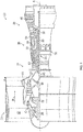
FIG. 1 is schematic cross-sectional view of an embodiment of a gas turbine engine; -
FIG. 2 is a schematic view of a combustor section and turbine section of an embodiment of a gas turbine engine; -
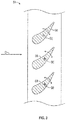
FIG. 3 is a schematic view of a vane row of an embodiment of a variable-area turbine (VAT) of a gas turbine engine; -
FIG. 4 is another schematic view of a combustor section and turbine section of a gas turbine engine; -
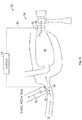
FIG. 5 is yet another schematic view of a combustor section and turbine section of a gas turbine engine; and -
FIG. 6 is a cross-sectional view of an embodiment of a combustor bypass valve. - A detailed description of one or more embodiments of the disclosed apparatus and method are presented herein by way of exemplification and not limitation with reference to the Figures.
-
FIG. 1 schematically illustrates agas turbine engine 20. Thegas turbine engine 20 is disclosed herein as a two-spool turbofan that generally incorporates afan section 22, acompressor section 24, acombustor section 26 and aturbine section 28. Alternative engines might include an augmentor section (not shown) among other systems or features. Thefan section 22 drives air along a bypass flow path B in a bypass duct, while thecompressor section 24 drives air along a core flow path C for compression and communication into thecombustor section 26 then expansion through theturbine section 28. Although depicted as a two-spool turbofan gas turbine engine in the disclosed non-limiting embodiment, it should be understood that the concepts described herein are not limited to use with two-spool turbofans as the teachings may be applied to other types of turbine engines including three-spool architectures. - The
exemplary engine 20 generally includes alow speed spool 30 and ahigh speed spool 32 mounted for rotation about an engine central longitudinal axis A relative to an enginestatic structure 36 viaseveral bearing systems 38. It should be understood thatvarious bearing systems 38 at various locations may alternatively or additionally be provided, and the location ofbearing systems 38 may be varied as appropriate to the application. - The
low speed spool 30 generally includes aninner shaft 40 that interconnects afan 42, alow pressure compressor 44 and alow pressure turbine 46. Theinner shaft 40 is connected to thefan 42 through a speed change mechanism, which in exemplarygas turbine engine 20 is illustrated as a gearedarchitecture 48 to drive thefan 42 at a lower speed than thelow speed spool 30. Thehigh speed spool 32 includes anouter shaft 50 that interconnects ahigh pressure compressor 52 andhigh pressure turbine 54. Acombustor 56 is arranged inexemplary gas turbine 20 between thehigh pressure compressor 52 and thehigh pressure turbine 54. An enginestatic structure 36 is arranged generally between thehigh pressure turbine 54 and thelow pressure turbine 46. The enginestatic structure 36 further supports bearingsystems 38 in theturbine section 28. Theinner shaft 40 and theouter shaft 50 are concentric and rotate viabearing systems 38 about the engine central longitudinal axis A which is collinear with their longitudinal axes. - The core airflow is compressed by the
low pressure compressor 44 then thehigh pressure compressor 52, mixed and burned with fuel in thecombustor 56, then expanded over thehigh pressure turbine 54 andlow pressure turbine 46. Theturbines low speed spool 30 andhigh speed spool 32 in response to the expansion. It will be appreciated that each of the positions of thefan section 22,compressor section 24,combustor section 26,turbine section 28, and fandrive gear system 48 may be varied. For example,gear system 48 may be located aft ofcombustor section 26 or even aft ofturbine section 28, andfan section 22 may be positioned forward or aft of the location ofgear system 48. - The
engine 20 in one example is a high-bypass geared aircraft engine. In a further example, theengine 20 bypass ratio is greater than about six (6), with an example embodiment being greater than about ten (10), the gearedarchitecture 48 is an epicyclic gear train, such as a planetary gear system or other gear system, with a gear reduction ratio of greater than about 2.3 and thelow pressure turbine 46 has a pressure ratio that is greater than about five. In one disclosed embodiment, theengine 20 bypass ratio is greater than about ten (10:1), the fan diameter is significantly larger than that of thelow pressure compressor 44, and thelow pressure turbine 46 has a pressure ratio that is greater than about five 5:1.Low pressure turbine 46 pressure ratio is pressure measured prior to inlet oflow pressure turbine 46 as related to the pressure at the outlet of thelow pressure turbine 46 prior to an exhaust nozzle. The gearedarchitecture 48 may be an epicycle gear train, such as a planetary gear system or other gear system, with a gear reduction ratio of greater than about 2.3:1. It should be understood, however, that the above parameters are only exemplary of one embodiment of a geared architecture engine and that the present disclosure is applicable to other gas turbine engines including direct drive turbofans. - A significant amount of thrust is provided by the bypass flow B due to the high bypass ratio. The
fan section 22 of theengine 20 is designed for a particular flight condition--typically cruise at about 0.8Mach and about 35,000 feet (10,688 meters). The flight condition of 0.8 Mach and 35,000 ft (10,688 meters), with the engine at its best fuel consumption--also known as "bucket cruise Thrust Specific Fuel Consumption ('TSFC')"--is the industry standard parameter of lbm of fuel being burned divided by lbf of thrust the engine produces at that minimum point. "Low fan pressure ratio" is the pressure ratio across the fan blade alone, without a Fan Exit Guide Vane ("FEGV") system. The low fan pressure ratio as disclosed herein according to one non-limiting embodiment is less than about 1.45. "Low corrected fan tip speed" is the actual fan tip speed in ft/sec divided by an industry standard temperature correction of [(Tram °R)/(518.7 °R)]0.5. The "Low corrected fan tip speed" as disclosed herein according to one non-limiting embodiment is less than about 1150 ft/second (350.5 m/sec). - Referring now to
FIG. 2 , theturbine section 28, for example, thehigh pressure turbine 54 is configured as a variable-area turbine (VAT), such that flow area of combustion products from thecombustor 56 along a flowpath D is changeable. In one embodiment, as illustrated inFIGs. 2 and3 , the flow area is changed by rotatingturbine vanes 58 about avane axis 60. It is to be appreciated that in other embodiments the flow area may be changed in other ways including changing the position of theturbine vanes 58 by sliding rather than rotating, or by moving other flowpath structure relative to theturbine vanes 58 to change the area of flowpath D. - Referring again to
FIG. 2 , thecombustor 56 includes a combustor inlet 62 to receive airflow from thehigh pressure compressor 24 along the core flowpath C, and to direct the airflow into thecombustor 56. The combustor inlet 62 is configured with an inlet cross-sectional area in which the airflow through the combustor inlet 62 is aerodynamically choked, or at a maximum flow velocity, when theturbine vanes 58 are positioned such that the area of flowpath D is at its minimum. - A
combustor bypass passage 64 is positioned with abypass inlet 66 along flowpath C upstream of the combustor inlet 62, and includes abypass outlet 68 at theturbine section 28. Further, thebypass inlet 66 is located downstream of thecompressor section 24. Thebypass passage 64 is configured to direct abypass airflow 70 around the combustor 56 from core flowpath C upstream of thecombustor 56 and reintroduce the bypass airflow into the flowpath D at theturbine section 28, for example, at thehigh pressure turbine 54 downstream of thevariable turbine blades 58. While thebypass passage 64 shown inFIG. 2 is located radially inboard of thecombustor 56, between the combustor and the engine central longitudinal axis A, in other embodiments thebypass passage 64 may be in another location, such as radially outboard of thecombustor 56. - A
combustor bypass valve 72 is located along thebypass passage 64, for example, at thebypass inlet 66 such as in the embodiment illustrated inFIG. 2 . It is to be appreciated, however, that thecombustor bypass valve 72 may be positioned at other locations of thebypass passage 64, such as at thebypass outlet 68 or at a location between thebypass inlet 66 and thebypass outlet 68. In some embodiments, thecombustor bypass valve 72 is an annular valve extending about the engine central longitudinal axis A, but it is to be appreciated that other valve types may be utilized. - Since the combustor inlet 62 is configured to be aerodynamically choked when the
turbine vanes 58 are positioned such that the area of flowpath D is at its minimum, excess airflow that cannot flow through the combustor inlet 62 because of the choked condition may be diverted through thebypass passage 64. As the area of flowpath D is increased from its minimum, a greater amount of airflow may be diverted through thebypass passage 64. Thecombustor bypass valve 72 regulates airflow through thebypass passage 64, to maintain the aerodynamically choked condition at the combustor inlet 62, thereby maintaining a selected level of combustor stability and efficiency, even with changes in the area of flowpath D. - To achieve this aim, the position of the
combustor bypass valve 72 is scheduled relative to flowpath D area, which in some embodiments corresponds to a position ofturbine vanes 58. Further, the scheduling may additionally take into account other operational parameters. Thecombustor bypass valve 72 is operably connected to acontroller 74, for example a full authority digital engine control (FADEC) along with a turbine vane actuation system shown schematically at 76 such that as thevane actuation system 76 movesturbine vanes 58 thus changing the flowpath D area, thecontroller 74 directs a change to the position ofcombustor bypass valve 72. For example, as theturbine vanes 58 are articulated to increase the flowpath D area, thecombustor bypass valve 72 is moved to an increased open position to allow a greater airflow through thebypass passage 64. Likewise as the flowpath D area is decreased, thecombustor valve 72 is moved to a more closed position to restrict the airflow through thebypass passage 64 to maintain the choked condition at the combustor inlet 62. - Referring now to
FIG. 4 , another embodiment is illustrated in which thebypass passage 64 is located radially outboard of thecombustor 56, rather than radially inboard of thecombustor 56 as in the embodiment ofFIG. 2 . Placement of thebypass passage 64 may depend on many factors, including available space for thebypass passage 64 and desired cross-sectional area of thebypass passage 64. - In yet another embodiment, illustrated in
FIG. 5 , thebypass airflow 70 is directed along thebypass passage 64 to another system connected to thegas turbine engine 20, such as an active cooling control (ACC) system, a heat exchanger (HEX) system, or the like. - Referring now to
FIG. 6 , anexemplary combustor valve 72 is illustrated. Thecombustor valve 72 includes avalve element 80, which is movable at abypass inlet 66 this regulating flow through thebypass passage 64. Thevalve element 80 extends partially around the engine central longitudinal axis A, and thecombustor valve 72 may include a plurality ofsuch valve elements 80 arrayed about the engine central longitudinal axis A over anannular bypass passage 64, centered on the engine central longitudinal axis A. In some embodiments, thevalve element 80 is movable via arocker arm 82 connected to thevalve element 80. Arod 84 is connected to therocker arm 82 such that translation of therod 84 in turn results in movement of therocker arm 82 about apivot 86. The movement of therocker arm 82 drives movement of thevalve element 80 between an opened position and a closed position. In some embodiments, therod 84 extends through acombustor inlet vane 88. It is to be appreciated that the configuration ofFIG. 6 is merely exemplary, and that other arrangements ofcombustor valve 72 may be utilized and are contemplated within the present scope. Further, while therocker arm 82 is utilized in the embodiment ofFIG. 6 , it is to be appreciated that other actuation mean, mechanical or electromechanical may be used to drive motion of thevalve element 80. - The arrangements disclosed herein provide for adjusting mass flow of the airflow into the
combustor 56 such that thecombustor 56 operation is tolerant to changes of turbine flowpath D area. This stabilizes operation of the combustor while also attaining the benefits of the variable turbine flowpath D. - The term "about" is intended to include the degree of error associated with measurement of the particular quantity based upon the equipment available at the time of filing the application.
- The terminology used herein is for the purpose of describing particular embodiments only and is not intended to be limiting of the present disclosure. As used herein, the singular forms "a", "an" and "the" are intended to include the plural forms as well, unless the context clearly indicates otherwise. It will be further understood that the terms "comprises" and/or "comprising," when used in this specification, specify the presence of stated features, integers, steps, operations, elements, and/or components, but do not preclude the presence or addition of one or more other features, integers, steps, operations, element components, and/or groups thereof.
- While the present disclosure has been described with reference to an exemplary embodiment or embodiments, it will be understood by those skilled in the art that various changes may be made and equivalents may be substituted for elements thereof without departing from the scope of the present disclosure. In addition, many modifications may be made to adapt a particular situation or material to the teachings of the present disclosure without departing from the essential scope thereof. Therefore, it is intended that the present disclosure not be limited to the particular embodiment disclosed as the best mode contemplated for carrying out this present disclosure, but that the present disclosure will include all embodiments falling within the scope of the claims.
Claims (15)
- A gas turbine engine (20), comprising:a variable area turbine (54), configured such that a flowpath area of the variable area turbine is selectably changeable;a combustor (56) disposed upstream of the variable area turbine, the combustor having a combustor inlet (62);a combustor bypass passage (64) having a passage inlet (66) disposed upstream of the combustor inlet and downstream of a compressor section (24) of the gas turbine engine, the combustor bypass passage configured to divert a selected bypass airflow (70) around the combustor; anda combustor bypass valve (72) disposed at the combustor bypass passage to control the selected bypass airflow along the combustor bypass passage.
- The gas turbine engine of claim 1, wherein the combustor inlet is configured to be in an aerodynamically choked state when the flowpath area of the variable area turbine is at a minimum area.
- The gas turbine engine of claim 1 or 2, wherein the combustor bypass valve is configured to move from a closed position toward a fully open position as the flowpath area of the variable area turbine is increased.
- The gas turbine engine of claim 1, 2 or 3 wherein the variable area turbine includes one or more turbine vanes (58), the one or more turbine vanes configured to be movable, thereby changing the flowpath area; optionally wherein the one or more turbine vanes are movable about a vane axis.
- The gas turbine engine of any preceding claim, wherein the combustor bypass passage includes a passage outlet (68) disposed at the variable area turbine.
- The gas turbine engine of any preceding claim, wherein the combustor bypass valve is disposed at the passage inlet; and/or wherein the combustor bypass valve is an annular valve.
- A combustor section (26) of a gas turbine engine (20), comprising:a combustor (56) having a combustor inlet (62);a combustor bypass passage (64) having a passage inlet (66) disposed upstream of the combustor inlet, the combustor bypass passage configured to divert a selected bypass airflow (70) around the combustor; anda combustor bypass valve (72) disposed at the combustor bypass passage to control the selected bypass airflow along the combustor bypass passage.
- The combustor section of claim 7, wherein the combustor inlet is configured to be in an aerodynamically choked state when a flowpath area of a variable area turbine (54) disposed downstream of the combustor is at a minimum area; optionally wherein the combustor bypass valve is configured to move from a closed position toward a fully open position as the flowpath area of the variable area turbine is increased.
- The combustor section of claim 7 or 8, wherein the combustor bypass passage includes a passage outlet (68) disposed at a turbine section (28) of the gas turbine engine.
- The combustor section of claim 7, 8 or 9, wherein the combustor bypass valve is disposed at the passage inlet; and/or wherein the combustor bypass valve is an annular valve.
- A method of operating a gas turbine engine (20), comprising:urging a core airflow from a compressor section (24) toward a combustor section (26) comprising a combustor (56);flowing a first portion of the core airflow into the combustor section via a combustor inlet (62); andflowing a second portion of the core airflow into a combustor bypass passage (64) via a combustor bypass valve (72), thereby bypassing the combustor with the second portion of the core airflow.
- The method of claim 11, further comprising:changing a flowpath area of a variable area turbine disposed downstream of the combustor; andchanging a combustor bypass valve position in response to the changing the flowpath area, thereby changing an amount of the second portion flowed through the combustor bypass passage; optionally wherein the combustor bypass valve is moved to an increasing open position in response to an increase in the flowpath area.
- The method of claim 12, wherein changing the flowpath area of the variable area turbine comprises rotating one or more turbine vanes (58) about a vane axis.
- The method of claim 11, 12 or 13, wherein the combustor inlet is configured to be in an aerodynamically choked state when a flowpath area of a variable area turbine disposed downstream of the combustor is at a minimum area.
- The method of any of claims 11 to 14, further comprising discharging the second portion into a turbine section (28) disposed downstream of the combustor via a bypass passage outlet (68).
Applications Claiming Priority (1)
| Application Number | Priority Date | Filing Date | Title |
|---|---|---|---|
| US15/782,423 US10830438B2 (en) | 2017-10-12 | 2017-10-12 | Modulated combustor bypass |
Publications (2)
| Publication Number | Publication Date |
|---|---|
| EP3470656A1 true EP3470656A1 (en) | 2019-04-17 |
| EP3470656B1 EP3470656B1 (en) | 2021-06-23 |
Family
ID=63857732
Family Applications (1)
| Application Number | Title | Priority Date | Filing Date |
|---|---|---|---|
| EP18200260.0A Active EP3470656B1 (en) | 2017-10-12 | 2018-10-12 | Modulated combustor bypass |
Country Status (2)
| Country | Link |
|---|---|
| US (1) | US10830438B2 (en) |
| EP (1) | EP3470656B1 (en) |
Families Citing this family (2)
| Publication number | Priority date | Publication date | Assignee | Title |
|---|---|---|---|---|
| US11060463B2 (en) * | 2018-01-08 | 2021-07-13 | Raytheon Technologies Corporation | Modulated combustor bypass and combustor bypass valve |
| US11821362B2 (en) * | 2022-04-13 | 2023-11-21 | Rtx Corporation | Gas turbine engine core debris cleaner |
Citations (3)
| Publication number | Priority date | Publication date | Assignee | Title |
|---|---|---|---|---|
| US5136840A (en) * | 1982-09-30 | 1992-08-11 | General Electric Company | Gas turbine engine actuation system |
| WO2011146096A2 (en) * | 2009-12-30 | 2011-11-24 | Rolls-Royce North American Technologies ,Inc | Combustor system |
| GB2530629A (en) * | 2014-08-19 | 2016-03-30 | Rolls Royce Plc | Method of operation of a gas turbine engine |
Family Cites Families (32)
| Publication number | Priority date | Publication date | Assignee | Title |
|---|---|---|---|---|
| DE881743C (en) * | 1944-01-06 | 1953-07-02 | Messerschmitt Boelkow Blohm | Process for preventing the flow in the compressors of hot jet engines from stalling |
| US2551229A (en) * | 1949-10-14 | 1951-05-01 | Gen Electric | Variable area nozzle and fluid injection control for turbojet engines |
| GB701324A (en) * | 1950-03-21 | 1953-12-23 | Rateau Soc | Improvements in jet or propeller turbine engines used for aircraft propulsion |
| US2637984A (en) * | 1950-07-26 | 1953-05-12 | Gen Electric | Turbine |
| US3029067A (en) * | 1956-05-31 | 1962-04-10 | Garrett Corp | Variable area nozzle means for turbines |
| US3094270A (en) * | 1958-08-05 | 1963-06-18 | Rolls Royce | Annular valve device |
| US3252686A (en) * | 1963-06-04 | 1966-05-24 | Chrysler Corp | Control mechanism for adjustable gas turbine nozzle |
| US3300966A (en) * | 1963-06-04 | 1967-01-31 | Chrysler Corp | Control mechanism for adjustable gas turbine nozzle |
| US3638428A (en) * | 1970-05-04 | 1972-02-01 | Gen Electric | Bypass valve mechanism |
| DE2740904A1 (en) * | 1977-09-10 | 1979-03-22 | Motoren Turbinen Union | DEVICE FOR OPERATING SHUT-OFF ELEMENTS IN GAS TURBINE ENGINES, IN PARTICULAR GAS TURBINE JET |
| US4185461A (en) | 1978-01-10 | 1980-01-29 | The United States Of America As Represented By The Secretary Of The Air Force | Turbojet engine with combustor bypass |
| US4270344A (en) * | 1978-05-19 | 1981-06-02 | General Motors Corporation | Hybrid dual shaft gas turbine with accumulator |
| US4387563A (en) * | 1979-06-20 | 1983-06-14 | General Motors Corporation | Articulated power turbine gate |
| FR2640685B1 (en) * | 1988-12-15 | 1991-02-08 | Snecma | TURBOREACTOR COMPRESSOR DISCHARGE VALVE |
| FR2649445B1 (en) * | 1989-07-05 | 1991-10-04 | Snecma | DISCHARGE DEVICE FOR A DOUBLE-FLOW GAS TURBINE ENGINE |
| US5123240A (en) * | 1990-03-19 | 1992-06-23 | General Electric Co. | Method and apparatus for ejecting foreign matter from the primary flow path of a gas turbine engine |
| US5182905A (en) * | 1990-05-11 | 1993-02-02 | General Electric Company | Method for automatic bypass operation |
| GB2259328B (en) * | 1991-09-03 | 1995-07-19 | Gen Electric | Gas turbine engine variable bleed pivotal flow splitter |
| US5596871A (en) * | 1995-05-31 | 1997-01-28 | Alliedsignal Inc. | Deceleration fuel control system for a turbine engine |
| JP2003329244A (en) | 2002-05-14 | 2003-11-19 | Mitsubishi Heavy Ind Ltd | Gas turbine combustor and combustion controlling method |
| US7549292B2 (en) * | 2005-10-03 | 2009-06-23 | General Electric Company | Method of controlling bypass air split to gas turbine combustor |
| US8438835B2 (en) | 2007-07-30 | 2013-05-14 | General Electric Company | Methods and apparatus for mixing fluid in turbine engines |
| EP3135920B1 (en) * | 2008-12-31 | 2018-12-19 | Rolls-Royce North American Technologies, Inc. | Variable pressure ratio compressor |
| US8668431B2 (en) * | 2010-03-29 | 2014-03-11 | United Technologies Corporation | Seal clearance control on non-cowled gas turbine engines |
| US9518513B2 (en) * | 2012-10-12 | 2016-12-13 | General Electric Company | Gas turbine engine two degree of freedom variable bleed valve for ice extraction |
| US9982598B2 (en) * | 2012-10-22 | 2018-05-29 | General Electric Company | Gas turbine engine variable bleed valve for ice extraction |
| ITFI20120292A1 (en) * | 2012-12-24 | 2014-06-25 | Nuovo Pignone Srl | "GAS TURBINES IN MECHANICAL DRIVE APPLICATIONS AND OPERATING METHODS" |
| DE102014217830A1 (en) * | 2014-09-05 | 2016-03-10 | Rolls-Royce Deutschland Ltd & Co Kg | Air guiding device and turbomachine with air guiding device |
| US10287992B2 (en) * | 2015-08-26 | 2019-05-14 | General Electric Company | Gas turbine engine hybrid variable bleed valve |
| US10502086B2 (en) * | 2016-03-16 | 2019-12-10 | General Electric Company | System and method for actuating gas turbine engine components using integrated jamming devices |
| US10208676B2 (en) * | 2016-03-29 | 2019-02-19 | General Electric Company | Gas turbine engine dual sealing cylindrical variable bleed valve |
| US10233845B2 (en) * | 2016-10-07 | 2019-03-19 | General Electric Company | Bleed valve assembly for a gas turbine engine |
-
2017
- 2017-10-12 US US15/782,423 patent/US10830438B2/en active Active
-
2018
- 2018-10-12 EP EP18200260.0A patent/EP3470656B1/en active Active
Patent Citations (3)
| Publication number | Priority date | Publication date | Assignee | Title |
|---|---|---|---|---|
| US5136840A (en) * | 1982-09-30 | 1992-08-11 | General Electric Company | Gas turbine engine actuation system |
| WO2011146096A2 (en) * | 2009-12-30 | 2011-11-24 | Rolls-Royce North American Technologies ,Inc | Combustor system |
| GB2530629A (en) * | 2014-08-19 | 2016-03-30 | Rolls Royce Plc | Method of operation of a gas turbine engine |
Also Published As
| Publication number | Publication date |
|---|---|
| US20190113232A1 (en) | 2019-04-18 |
| US10830438B2 (en) | 2020-11-10 |
| EP3470656B1 (en) | 2021-06-23 |
Similar Documents
| Publication | Publication Date | Title |
|---|---|---|
| EP3795811B1 (en) | Engine bleed air ducting into heat exchanger duct | |
| US9957832B2 (en) | Variable area turbine | |
| EP3406883B1 (en) | Actively-driven bleed source switching | |
| EP2957754B1 (en) | Variable area nozzle for gas turbine engine | |
| US10094229B2 (en) | Cooling system of a stator assembly for a gas turbine engine having a variable cooling flow mechanism and method of operation | |
| EP3239493B1 (en) | Simple heat exchanger using super alloy materials | |
| EP3620698B1 (en) | Globe butterfly valve | |
| EP3330524A1 (en) | Heat exchanger mounted at rear of gas turbine engine for challenging temperature applications | |
| EP3406882B1 (en) | Active bleed flow modulation | |
| EP3470656B1 (en) | Modulated combustor bypass | |
| EP3617460B1 (en) | Dual valve system with different valve disc geometries | |
| EP3623584B1 (en) | Set screw gap control between fixed and variable vanes | |
| EP3296548B1 (en) | Heat exchanger for gas turbine engine mounted in intermediate case | |
| US10480326B2 (en) | Vane for variable area turbine | |
| EP3508790B1 (en) | Gas turbine engine with modulated combustor bypass and combustor bypass valve | |
| EP3460226B1 (en) | Moveable exhaust plug liner | |
| EP3181869A1 (en) | Compressor core inner diameter cooling | |
| EP3348812B1 (en) | Cooled gas turbine engine cooling air with cold air dump |
Legal Events
| Date | Code | Title | Description |
|---|---|---|---|
| PUAI | Public reference made under article 153(3) epc to a published international application that has entered the european phase |
Free format text: ORIGINAL CODE: 0009012 |
|
| STAA | Information on the status of an ep patent application or granted ep patent |
Free format text: STATUS: THE APPLICATION HAS BEEN PUBLISHED |
|
| AK | Designated contracting states |
Kind code of ref document: A1 Designated state(s): AL AT BE BG CH CY CZ DE DK EE ES FI FR GB GR HR HU IE IS IT LI LT LU LV MC MK MT NL NO PL PT RO RS SE SI SK SM TR |
|
| AX | Request for extension of the european patent |
Extension state: BA ME |
|
| STAA | Information on the status of an ep patent application or granted ep patent |
Free format text: STATUS: REQUEST FOR EXAMINATION WAS MADE |
|
| 17P | Request for examination filed |
Effective date: 20191017 |
|
| RBV | Designated contracting states (corrected) |
Designated state(s): AL AT BE BG CH CY CZ DE DK EE ES FI FR GB GR HR HU IE IS IT LI LT LU LV MC MK MT NL NO PL PT RO RS SE SI SK SM TR |
|
| GRAP | Despatch of communication of intention to grant a patent |
Free format text: ORIGINAL CODE: EPIDOSNIGR1 |
|
| STAA | Information on the status of an ep patent application or granted ep patent |
Free format text: STATUS: GRANT OF PATENT IS INTENDED |
|
| INTG | Intention to grant announced |
Effective date: 20200623 |
|
| GRAJ | Information related to disapproval of communication of intention to grant by the applicant or resumption of examination proceedings by the epo deleted |
Free format text: ORIGINAL CODE: EPIDOSDIGR1 |
|
| STAA | Information on the status of an ep patent application or granted ep patent |
Free format text: STATUS: REQUEST FOR EXAMINATION WAS MADE |
|
| INTC | Intention to grant announced (deleted) | ||
| GRAP | Despatch of communication of intention to grant a patent |
Free format text: ORIGINAL CODE: EPIDOSNIGR1 |
|
| STAA | Information on the status of an ep patent application or granted ep patent |
Free format text: STATUS: GRANT OF PATENT IS INTENDED |
|
| INTG | Intention to grant announced |
Effective date: 20210121 |
|
| RAP1 | Party data changed (applicant data changed or rights of an application transferred) |
Owner name: RAYTHEON TECHNOLOGIES CORPORATION |
|
| GRAS | Grant fee paid |
Free format text: ORIGINAL CODE: EPIDOSNIGR3 |
|
| GRAA | (expected) grant |
Free format text: ORIGINAL CODE: 0009210 |
|
| STAA | Information on the status of an ep patent application or granted ep patent |
Free format text: STATUS: THE PATENT HAS BEEN GRANTED |
|
| AK | Designated contracting states |
Kind code of ref document: B1 Designated state(s): AL AT BE BG CH CY CZ DE DK EE ES FI FR GB GR HR HU IE IS IT LI LT LU LV MC MK MT NL NO PL PT RO RS SE SI SK SM TR |
|
| REG | Reference to a national code |
Ref country code: GB Ref legal event code: FG4D |
|
| REG | Reference to a national code |
Ref country code: CH Ref legal event code: EP |
|
| REG | Reference to a national code |
Ref country code: DE Ref legal event code: R096 Ref document number: 602018018912 Country of ref document: DE Ref country code: AT Ref legal event code: REF Ref document number: 1404518 Country of ref document: AT Kind code of ref document: T Effective date: 20210715 |
|
| REG | Reference to a national code |
Ref country code: IE Ref legal event code: FG4D |
|
| REG | Reference to a national code |
Ref country code: LT Ref legal event code: MG9D |
|
| PG25 | Lapsed in a contracting state [announced via postgrant information from national office to epo] |
Ref country code: FI Free format text: LAPSE BECAUSE OF FAILURE TO SUBMIT A TRANSLATION OF THE DESCRIPTION OR TO PAY THE FEE WITHIN THE PRESCRIBED TIME-LIMIT Effective date: 20210623 Ref country code: LT Free format text: LAPSE BECAUSE OF FAILURE TO SUBMIT A TRANSLATION OF THE DESCRIPTION OR TO PAY THE FEE WITHIN THE PRESCRIBED TIME-LIMIT Effective date: 20210623 Ref country code: HR Free format text: LAPSE BECAUSE OF FAILURE TO SUBMIT A TRANSLATION OF THE DESCRIPTION OR TO PAY THE FEE WITHIN THE PRESCRIBED TIME-LIMIT Effective date: 20210623 Ref country code: BG Free format text: LAPSE BECAUSE OF FAILURE TO SUBMIT A TRANSLATION OF THE DESCRIPTION OR TO PAY THE FEE WITHIN THE PRESCRIBED TIME-LIMIT Effective date: 20210923 |
|
| REG | Reference to a national code |
Ref country code: AT Ref legal event code: MK05 Ref document number: 1404518 Country of ref document: AT Kind code of ref document: T Effective date: 20210623 |
|
| PG25 | Lapsed in a contracting state [announced via postgrant information from national office to epo] |
Ref country code: LV Free format text: LAPSE BECAUSE OF FAILURE TO SUBMIT A TRANSLATION OF THE DESCRIPTION OR TO PAY THE FEE WITHIN THE PRESCRIBED TIME-LIMIT Effective date: 20210623 Ref country code: NO Free format text: LAPSE BECAUSE OF FAILURE TO SUBMIT A TRANSLATION OF THE DESCRIPTION OR TO PAY THE FEE WITHIN THE PRESCRIBED TIME-LIMIT Effective date: 20210923 Ref country code: RS Free format text: LAPSE BECAUSE OF FAILURE TO SUBMIT A TRANSLATION OF THE DESCRIPTION OR TO PAY THE FEE WITHIN THE PRESCRIBED TIME-LIMIT Effective date: 20210623 Ref country code: SE Free format text: LAPSE BECAUSE OF FAILURE TO SUBMIT A TRANSLATION OF THE DESCRIPTION OR TO PAY THE FEE WITHIN THE PRESCRIBED TIME-LIMIT Effective date: 20210623 Ref country code: GR Free format text: LAPSE BECAUSE OF FAILURE TO SUBMIT A TRANSLATION OF THE DESCRIPTION OR TO PAY THE FEE WITHIN THE PRESCRIBED TIME-LIMIT Effective date: 20210924 |
|
| REG | Reference to a national code |
Ref country code: NL Ref legal event code: MP Effective date: 20210623 |
|
| PG25 | Lapsed in a contracting state [announced via postgrant information from national office to epo] |
Ref country code: SM Free format text: LAPSE BECAUSE OF FAILURE TO SUBMIT A TRANSLATION OF THE DESCRIPTION OR TO PAY THE FEE WITHIN THE PRESCRIBED TIME-LIMIT Effective date: 20210623 Ref country code: SK Free format text: LAPSE BECAUSE OF FAILURE TO SUBMIT A TRANSLATION OF THE DESCRIPTION OR TO PAY THE FEE WITHIN THE PRESCRIBED TIME-LIMIT Effective date: 20210623 Ref country code: EE Free format text: LAPSE BECAUSE OF FAILURE TO SUBMIT A TRANSLATION OF THE DESCRIPTION OR TO PAY THE FEE WITHIN THE PRESCRIBED TIME-LIMIT Effective date: 20210623 Ref country code: ES Free format text: LAPSE BECAUSE OF FAILURE TO SUBMIT A TRANSLATION OF THE DESCRIPTION OR TO PAY THE FEE WITHIN THE PRESCRIBED TIME-LIMIT Effective date: 20210623 Ref country code: CZ Free format text: LAPSE BECAUSE OF FAILURE TO SUBMIT A TRANSLATION OF THE DESCRIPTION OR TO PAY THE FEE WITHIN THE PRESCRIBED TIME-LIMIT Effective date: 20210623 Ref country code: AT Free format text: LAPSE BECAUSE OF FAILURE TO SUBMIT A TRANSLATION OF THE DESCRIPTION OR TO PAY THE FEE WITHIN THE PRESCRIBED TIME-LIMIT Effective date: 20210623 Ref country code: NL Free format text: LAPSE BECAUSE OF FAILURE TO SUBMIT A TRANSLATION OF THE DESCRIPTION OR TO PAY THE FEE WITHIN THE PRESCRIBED TIME-LIMIT Effective date: 20210623 Ref country code: PT Free format text: LAPSE BECAUSE OF FAILURE TO SUBMIT A TRANSLATION OF THE DESCRIPTION OR TO PAY THE FEE WITHIN THE PRESCRIBED TIME-LIMIT Effective date: 20211025 Ref country code: RO Free format text: LAPSE BECAUSE OF FAILURE TO SUBMIT A TRANSLATION OF THE DESCRIPTION OR TO PAY THE FEE WITHIN THE PRESCRIBED TIME-LIMIT Effective date: 20210623 |
|
| PG25 | Lapsed in a contracting state [announced via postgrant information from national office to epo] |
Ref country code: PL Free format text: LAPSE BECAUSE OF FAILURE TO SUBMIT A TRANSLATION OF THE DESCRIPTION OR TO PAY THE FEE WITHIN THE PRESCRIBED TIME-LIMIT Effective date: 20210623 |
|
| REG | Reference to a national code |
Ref country code: DE Ref legal event code: R097 Ref document number: 602018018912 Country of ref document: DE |
|
| PG25 | Lapsed in a contracting state [announced via postgrant information from national office to epo] |
Ref country code: DK Free format text: LAPSE BECAUSE OF FAILURE TO SUBMIT A TRANSLATION OF THE DESCRIPTION OR TO PAY THE FEE WITHIN THE PRESCRIBED TIME-LIMIT Effective date: 20210623 |
|
| PLBE | No opposition filed within time limit |
Free format text: ORIGINAL CODE: 0009261 |
|
| STAA | Information on the status of an ep patent application or granted ep patent |
Free format text: STATUS: NO OPPOSITION FILED WITHIN TIME LIMIT |
|
| REG | Reference to a national code |
Ref country code: CH Ref legal event code: PL |
|
| 26N | No opposition filed |
Effective date: 20220324 |
|
| PG25 | Lapsed in a contracting state [announced via postgrant information from national office to epo] |
Ref country code: AL Free format text: LAPSE BECAUSE OF FAILURE TO SUBMIT A TRANSLATION OF THE DESCRIPTION OR TO PAY THE FEE WITHIN THE PRESCRIBED TIME-LIMIT Effective date: 20210623 |
|
| REG | Reference to a national code |
Ref country code: BE Ref legal event code: MM Effective date: 20211031 |
|
| PG25 | Lapsed in a contracting state [announced via postgrant information from national office to epo] |
Ref country code: MC Free format text: LAPSE BECAUSE OF FAILURE TO SUBMIT A TRANSLATION OF THE DESCRIPTION OR TO PAY THE FEE WITHIN THE PRESCRIBED TIME-LIMIT Effective date: 20210623 |
|
| PG25 | Lapsed in a contracting state [announced via postgrant information from national office to epo] |
Ref country code: LU Free format text: LAPSE BECAUSE OF NON-PAYMENT OF DUE FEES Effective date: 20211012 Ref country code: IT Free format text: LAPSE BECAUSE OF FAILURE TO SUBMIT A TRANSLATION OF THE DESCRIPTION OR TO PAY THE FEE WITHIN THE PRESCRIBED TIME-LIMIT Effective date: 20210623 Ref country code: BE Free format text: LAPSE BECAUSE OF NON-PAYMENT OF DUE FEES Effective date: 20211031 |
|
| PG25 | Lapsed in a contracting state [announced via postgrant information from national office to epo] |
Ref country code: LI Free format text: LAPSE BECAUSE OF NON-PAYMENT OF DUE FEES Effective date: 20211031 Ref country code: CH Free format text: LAPSE BECAUSE OF NON-PAYMENT OF DUE FEES Effective date: 20211031 |
|
| PG25 | Lapsed in a contracting state [announced via postgrant information from national office to epo] |
Ref country code: IE Free format text: LAPSE BECAUSE OF NON-PAYMENT OF DUE FEES Effective date: 20211012 |
|
| P01 | Opt-out of the competence of the unified patent court (upc) registered |
Effective date: 20230521 |
|
| PG25 | Lapsed in a contracting state [announced via postgrant information from national office to epo] |
Ref country code: CY Free format text: LAPSE BECAUSE OF FAILURE TO SUBMIT A TRANSLATION OF THE DESCRIPTION OR TO PAY THE FEE WITHIN THE PRESCRIBED TIME-LIMIT Effective date: 20210623 |
|
| PG25 | Lapsed in a contracting state [announced via postgrant information from national office to epo] |
Ref country code: HU Free format text: LAPSE BECAUSE OF FAILURE TO SUBMIT A TRANSLATION OF THE DESCRIPTION OR TO PAY THE FEE WITHIN THE PRESCRIBED TIME-LIMIT; INVALID AB INITIO Effective date: 20181012 |
|
| PG25 | Lapsed in a contracting state [announced via postgrant information from national office to epo] |
Ref country code: MK Free format text: LAPSE BECAUSE OF FAILURE TO SUBMIT A TRANSLATION OF THE DESCRIPTION OR TO PAY THE FEE WITHIN THE PRESCRIBED TIME-LIMIT Effective date: 20210623 |
|
| PG25 | Lapsed in a contracting state [announced via postgrant information from national office to epo] |
Ref country code: MT Free format text: LAPSE BECAUSE OF FAILURE TO SUBMIT A TRANSLATION OF THE DESCRIPTION OR TO PAY THE FEE WITHIN THE PRESCRIBED TIME-LIMIT Effective date: 20210623 |
|
| REG | Reference to a national code |
Ref country code: DE Ref legal event code: R081 Ref document number: 602018018912 Country of ref document: DE Owner name: RTX CORPORATION (N.D.GES.D. STAATES DELAWARE),, US Free format text: FORMER OWNER: RAYTHEON TECHNOLOGIES CORP., FARMINGTON, CT, US |
|
| PGFP | Annual fee paid to national office [announced via postgrant information from national office to epo] |
Ref country code: GB Payment date: 20250923 Year of fee payment: 8 |
|
| PGFP | Annual fee paid to national office [announced via postgrant information from national office to epo] |
Ref country code: FR Payment date: 20250923 Year of fee payment: 8 |
|
| PG25 | Lapsed in a contracting state [announced via postgrant information from national office to epo] |
Ref country code: TR Free format text: LAPSE BECAUSE OF FAILURE TO SUBMIT A TRANSLATION OF THE DESCRIPTION OR TO PAY THE FEE WITHIN THE PRESCRIBED TIME-LIMIT Effective date: 20210623 |
|
| PGFP | Annual fee paid to national office [announced via postgrant information from national office to epo] |
Ref country code: DE Payment date: 20250923 Year of fee payment: 8 |