EP3470654B1 - Cooling structure of engine - Google Patents
Cooling structure of engine Download PDFInfo
- Publication number
- EP3470654B1 EP3470654B1 EP18199235.5A EP18199235A EP3470654B1 EP 3470654 B1 EP3470654 B1 EP 3470654B1 EP 18199235 A EP18199235 A EP 18199235A EP 3470654 B1 EP3470654 B1 EP 3470654B1
- Authority
- EP
- European Patent Office
- Prior art keywords
- cooling fluid
- cylinder
- channel
- bore
- water jacket
- Prior art date
- Legal status (The legal status is an assumption and is not a legal conclusion. Google has not performed a legal analysis and makes no representation as to the accuracy of the status listed.)
- Active
Links
Images








Classifications
-
- F—MECHANICAL ENGINEERING; LIGHTING; HEATING; WEAPONS; BLASTING
- F01—MACHINES OR ENGINES IN GENERAL; ENGINE PLANTS IN GENERAL; STEAM ENGINES
- F01P—COOLING OF MACHINES OR ENGINES IN GENERAL; COOLING OF INTERNAL-COMBUSTION ENGINES
- F01P3/00—Liquid cooling
- F01P3/02—Arrangements for cooling cylinders or cylinder heads
-
- F—MECHANICAL ENGINEERING; LIGHTING; HEATING; WEAPONS; BLASTING
- F02—COMBUSTION ENGINES; HOT-GAS OR COMBUSTION-PRODUCT ENGINE PLANTS
- F02F—CYLINDERS, PISTONS OR CASINGS, FOR COMBUSTION ENGINES; ARRANGEMENTS OF SEALINGS IN COMBUSTION ENGINES
- F02F1/00—Cylinders; Cylinder heads
- F02F1/02—Cylinders; Cylinder heads having cooling means
- F02F1/10—Cylinders; Cylinder heads having cooling means for liquid cooling
-
- F—MECHANICAL ENGINEERING; LIGHTING; HEATING; WEAPONS; BLASTING
- F02—COMBUSTION ENGINES; HOT-GAS OR COMBUSTION-PRODUCT ENGINE PLANTS
- F02F—CYLINDERS, PISTONS OR CASINGS, FOR COMBUSTION ENGINES; ARRANGEMENTS OF SEALINGS IN COMBUSTION ENGINES
- F02F1/00—Cylinders; Cylinder heads
- F02F1/02—Cylinders; Cylinder heads having cooling means
- F02F1/10—Cylinders; Cylinder heads having cooling means for liquid cooling
- F02F1/14—Cylinders with means for directing, guiding or distributing liquid stream
-
- F—MECHANICAL ENGINEERING; LIGHTING; HEATING; WEAPONS; BLASTING
- F01—MACHINES OR ENGINES IN GENERAL; ENGINE PLANTS IN GENERAL; STEAM ENGINES
- F01P—COOLING OF MACHINES OR ENGINES IN GENERAL; COOLING OF INTERNAL-COMBUSTION ENGINES
- F01P3/00—Liquid cooling
- F01P3/02—Arrangements for cooling cylinders or cylinder heads
- F01P2003/021—Cooling cylinders
Definitions
- the present disclosure belongs to a technical field related to a cooling structure of an engine, particularly a multi-cylinder engine.
- a cooling structure of an engine particularly a multi-cylinder engine
- a structure in which a water jacket is formed in a cylinder block so as to surround the perimeter of a plurality of cylinder bores (a plurality of cylinder bore walls) and cooling fluid pumped by a water pump is introduced into the water jacket to cool an engine.
- JP2017-089563A a structure is known in which an inter-bore channel is provided to a part of a cylinder block (cylinder bore wall) between adjacent cylinder bores to allow cooling fluid in the water jacket to flow into a cylinder head to cool the part between the cylinder bores which tends to be at a high temperature.
- a guide part is formed in a water jacket spacer accommodated in the water jacket of the cylinder block to lead the cooling fluid into an inlet of the inter-bore channel.
- combustion chambers of the engine it is necessary to keep combustion chambers of the engine warm in order to secure an environment for stabilizing compression ignition of fuel, i.e., in order to maintain the temperature of the combustion chambers at a temperature where compression ignition is possible. Further, it is necessary to cool the combustion chambers especially when the engine is operating at a high load.
- the water jacket spacer of JP2017-089563A overlaps with an inner side-wall surface of the water jacket (an outer side surface of the cylinder bore wall), and therefore almost no gap can be formed between the water jacket spacer and the inner side-wall surface of the water jacket. Moreover, a part of the water jacket spacer on the cylinder head side only has the guide part and does not cover the cylinder bore wall. Thus, although the structure of JP2017-089563A can secure the cooling performance of the combustion chambers, it is difficult to secure the heat retention performance of the combustion chambers.
- US 2005/217615 A1 discloses a cooling structure for cooling a bore wall of a cylinder block using a cooling medium.
- JP 2015 078675 A discloses a cooling system of an engine aimed to sufficiently prevent cooling water from flowing into a gap between a spacer member accommodated in a water jacket and a cylinder bore wall, in a section having relatively strong flow of the cooling water.
- the present disclosure is made in view of the situations described above, and it is to provide a cooling structure of an engine, which achieves securing both cooling performance and heat retention performance of the combustion chambers.
- a cooling structure of an engine is defined in claim 1.
- the peripheral wall is configured to correspond to the plurality of cylinder bores.
- a length of the peripheral wall in cylinder bore axial directions is substantially the same as a length of the water jacket in the cylinder bore axial directions.
- inter-bore channels is configured such that cooling fluid, particularly some of the cooling fluid, which flows from the outer channel into the inner channel through the communicating holes, flows into the inter-bore channels.
- a cooling fluid inlet which is configured to communicate with the outer channel, is provided to the cylinder block.
- the cooling fluid inlet is configured such that the cooling fluid flows into the outer channel through the cooling fluid inlet.
- the engine is an in-series multi-cylinder engine.
- the engine may be an in-series 2-cylinder engine, an in-series 3-cylinder engine, an in-series 4-cylinder engine, an in-series 5-cylinder engine, or an in-series 6-cylinder engine.
- cooling fluid inlet is configured to communicate with a part of the outer channel on a first side in cylinder line-up directions.
- a route, along which the cooling fluid flows is configured such that the cooling fluid flows sequentially from the part of the outer channel on the first side, through a part on an exhaust side and a part on a second side in the cylinder line-up directions, and into a part on an intake side.
- the cooling fluid flows into the outer channel from the cooling fluid inlet and flows through the outer channel.
- a rib is formed in the part of an inner-channel-side surface of the peripheral wall on the first side.
- the rib is configured to disrupt the cooling fluid flowing in the circumferential directions in the part of the inner channel on the first side.
- an engine includes, a cylinder block, a plurality of cylinder bores formed in the cylinder block, a cylinder head, and the cooling structure as described above.
- the cooling structure includes a water jacket configured to surround the plurality of cylinder bores, and a water jacket spacer accommodated in the water jacket of the cylinder block and having a peripheral wall.
- a cooling structure of a multi-cylinder engine having a cylinder block which includes a plurality of cylinder bores formed in the cylinder block, a water jacket surrounding the plurality of cylinder bores, a cylinder head, and a water jacket spacer accommodated in the water jacket of the cylinder block and having a peripheral wall formed to correspond to the plurality of cylinder bores.
- a length of the peripheral wall in cylinder bore axial directions is substantially the same as a length of the water jacket in the cylinder bore axial directions.
- the peripheral wall forms, inside the water jacket, an inner channel located inside the peripheral wall and an outer channel located outside the peripheral wall.
- a width of the inner channel is less than a width of the outer channel.
- Communicating holes communicating the inner channel with the outer channel are formed in the peripheral wall at locations between adjacent cylinder bores, respectively.
- Inter-bore channels into which some of cooling fluid flowing from the outer channel into the inner channel through the communicating holes flows are provided to parts of the cylinder block between the adjacent cylinder bores, respectively.
- the inner channel and the outer channel are partitioned by the peripheral wall, thereby fundamentally communicating with each other only at the communicating holes.
- the cooling fluid when the cooling fluid is flowed into the water jacket from outside of the cylinder block, normally, the fluid is flowed into the outer channel which is located outside the peripheral wall.
- the cooling fluid may flow into both the outer and inner channels, since the width of the inner channel is less than the width of the outer channel, it is difficult for the cooling fluid to flow inside the inner channel.
- the inner channel it is difficult for fresh cooling fluid to flow and it is stagnated. Therefore, heat retention performance of the combustion chamber of the multi-cylinder engine can be secured by the cooling fluid in a stagnated state.
- the cooling fluid in the outer channel, can be flowed vigorously, and some of the cooling fluid flows into the inner channel through the communicating holes and some of the cooling fluid which inflowed then flows into the inter-bore channels.
- the cooling performance of the combustion chamber of the multi-cylinder engine can be secured, and the majority of the cooling fluid in the inner channel can be maintained in the stagnated state.
- the cooling performance of the combustion chamber of the multi-cylinder engine can be secured, and the heat retention performance of the combustion chamber can be secured by the cooling fluid inside the inner channel.
- a part of the inner circumferential surface of each communicating hole on a cylinder head side inclines toward the inlet of the corresponding inter-bore channel.
- a part of the inner circumferential surface of each communicating hole on an opposite side of the cylinder head inclines toward a location below the inlet of the corresponding inter-bore channel.
- a large amount of the cooling fluid which flowed into the inner channel through the communicating holes from the outer channel can be flowed into the inter-bore channels, and a portion of the cooling fluid which flowed into the inner channel through the communicating holes can be assigned to the lower part of the inlets of the inter-bore channels in an outer side surface of a cylinder bore wall.
- the cylinder bore wall can also be cooled from the outer side surface.
- a cooling fluid inlet communicating with the outer channel may be provided to the cylinder block, the cooling fluid flowing into the outer channel cooling fluid inlet.
- the cooling fluid in the inner channel can be made into a more stagnated state. Further, the cooling fluid can be flowed vigorously from the outer channel to the inner channel through the communicating hole, and a large amount of the cooling fluid can be flowed into the inter-bore channel through the communicating hole.
- the multi-cylinder engine may be an in-series multi-cylinder engine.
- the cooling fluid inlet may communicate with a part of the outer channel on a first side in cylinder line-up directions.
- the cooling fluid flowing into the outer channel from the cooling fluid inlet and flowing through the outer channel may flow along a route sequentially from the part of the outer channel on the first side, through a part on an exhaust side and a part on a second side in the cylinder line-up directions, and into a part on an intake side.
- a rib configured to disrupt the cooling fluid flowing in the circumferential directions in the part of the inner channel on the first side in the cylinder line-up directions may be formed in the part of an inner-channel-side surface of the peripheral wall on the first side.
- the cooling fluid which did not flow into the inter-bore channels, of the cooling fluid which flowed into the inner channel through the communicating holes from the part of the outer channel on the exhaust side does not flow toward the part formed with the rib in the inner channel, but instead flows to the second side in the cylinder line-up directions similar to the cooling fluid flowing in the outer channel on the exhaust side.
- the part of the cylinder bore wall on the exhaust side which gets particularly hot can be cooled over the large area in the circumferential directions, and the cooling performance of the combustion chamber of the multi-cylinder engine can further be secured.
- the cooling fluid which did not flow into the inter-bore channels is difficult to spread in the cylinder bore axial directions of the inner channel, and basically, it flows toward the second side in the cylinder line-up directions at substantially the same location with the communicating holes in the cylinder bore axial directions. Therefore, the majority of the cooling fluid in the inner channel can be maintained in the stagnated state and the heat retention performance of the combustion chamber of the multi-cylinder engine can be secured.
- Figs. 1 and 2 illustrate a cylinder block 1 of an engine, particularly an multi-cylinder engine, to which a cooling structure according to one embodiment of the present disclosure is applied (hereinafter, simply referred to as "the engine”).
- the engine is an in-line 4-cylinder diesel engine, having a cylinder block 1 provided with four cylinder bores 2 arranged in-line, and cylindrical-shaped cylinder bore walls 2a surrounding the perimeters of the cylinder bores 2, respectively. Adjacent cylinder bore walls 2a are integrally coupled to each other, and this type of cylinder block 1 is called a Siamese cylinder block. A part of the cylinder bore walls 2a between the adjacent cylinder bores 2 is narrowed.
- the engine may be an in-line 2-cylinder diesel engine, an in-line 3-cylinder diesel engine, an in-line 4-cylinder diesel engine, an in-line 5-cylinder diesel engine, or an in-line 6-cylinder diesel engine.
- the engine is mounted in an engine bay located at a front part of a vehicle so that cylinder line-up directions are oriented in vehicle width directions and cylinder bore axial directions are oriented in vertical directions.
- a lower right side of Fig. 1 and a lower side of Fig. 2 correspond to an intake side through which intake air is introduced into the engine
- an upper left side of Fig. 1 and an upper side of Fig. 2 correspond to an exhaust side through which exhaust gas is discharged from the engine.
- a transmission (not illustrated) is attached to an end face of the cylinder block 1 on the left side of the vehicle (right side of Fig. 2 ).
- the engine shall be in a state where it is mounted in the vehicle.
- a heater plug-in hole 3 into which a block heater (not illustrated) used in a cold region is inserted by a crew member is formed in a part in an intake-side surface of the cylinder block 1 on the transmission side.
- a cylinder head 35 is attached to an upper surface of the cylinder block 1 (i.e., a surface of the cylinder block 1 on a first side in the cylinder bore axial directions) through a gasket 36.
- Eight tapped holes 4 with which bolts (not illustrated) for attaching and fixing the cylinder head 35 to the cylinder block 1 threadedly engage are formed in the upper surface of the cylinder block 1.
- the cylinder block 1 is provided with a block water jacket 7 which surrounds the perimeter of the four cylinder bores 2 (four cylinder bore walls 2a).
- the number of the cylinder bores and the cylinder bore walls may be two, three, four, five, six or more.
- the block water jacket 7 is formed in a deep groove shape so as to open in the upper surface of the cylinder block 1. This opening is closed by the gasket 36 when the cylinder head 35 is attached to the upper surface of the cylinder lock 1 through the gasket 36.
- a side wall inside the block water jacket 7 is comprised of the cylinder bore walls 2a.
- a side wall surface inside the block water jacket 7 is comprised of an outer side surface of the cylinder bore wall 2a.
- the block water jacket 7 is curved inwardly so as to be closer to an imaginary central plane including all the centerlines of the four cylinder bores 2, corresponding to intake and exhaust side parts of the cylinder bore walls 2a between adjacent cylinder bores 2.
- each of the intake and exhaust side parts of the cylinder bore walls 2a between the adjacent cylinder bores 2 is referred to as a "necked part 2b.” Therefore, in this embodiment, a total of six necked parts 2b are formed in the cylinder bore walls 2a.
- the block water jacket 7 is provided, in a part thereof on the intake side and the opposite side of the transmission, with a cooling fluid introducing part 7a through which the cooling fluid is introduced into the block water jacket 7.
- a cooling fluid inlet 8 through which the cooling fluid (e.g., engine cooling water or coolant) flows into the block water jacket 7 is provided in a part of the intake-side surface of the cylinder block 1 on the opposite side of the transmission.
- the cooling fluid inlet 8 communicates with the cooling fluid introducing part 7a through a communicating channel 9 (see Fig. 3 ) having a rectangular cross-sectional shape provided in the intake-side wall part of the cylinder block 1.
- the cooling fluid inlet 8 communicates with the block water jacket 7 (in detail, with an outer channel 7c described below).
- the cooling fluid inlet 8 is connected with a discharge port of a water pump (not illustrated).
- the cooling fluid discharged from the discharge port of the water pump is introduced into the cooling fluid introducing part 7a through the cooling fluid inlet 8 and the communicating channel 9, and then flows into the block water jacket 7 (in detail, the outer channel 7c described below) from the cooling fluid introducing part 7a.
- the communicating channel 9 opens in the outer side-wall surface of the block water jacket 7 (in detail, the side wall surface of the cooling fluid introducing part 7a).
- a lower surface of the opening is located higher than a bottom surface of the cooling fluid introducing part 7a, thereby producing a stepped part between the lower surface of the opening and the bottom surface of the cooling fluid introducing part 7a.
- the stepped part is produced because of a directional difference of removing molds between a mold for the communicating channel 9 (removed toward the cooling fluid inlet 8) and a mold for the block water jacket 7 (removed upwardly) when casting the cylinder block 1.
- the water jacket spacer 11 is made particularly of resin.
- the height of the peripheral wall 12 i.e., a length in the cylinder bore axial directions
- the peripheral wall 12 of the water jacket spacer 11 has cylindrical shapes surrounding the four cylinder bores 2 (four cylinder bore walls 2a). Note that the peripheral wall 12 may be partially separated or divided in circumferential directions.
- the water jacket spacer 11 is constructed by the peripheral wall 12 of the water jacket spacer 11 so that an inner channel 7b located inside the peripheral wall 12 (on the cylinder bore wall 2a side) and an outer channel 7c located outside the peripheral wall 12 (on the opposite side from the cylinder bore wall 2a) are formed in the water jacket 7 (particularly, see Fig. 10 ).
- a width of the inner channel 7b (a distance between the inner surface of the peripheral wall 12 and the inner side-wall surface of the water jacket 7) is less than a width of the outer channel 7c (a distance between the outer surface of the peripheral wall 12 and the outer side-wall surface of the water jacket 7).
- the peripheral wall 12 of the water jacket spacer 11 has, similar to the water jacket 7, six inwardly bent parts 13 which curve inwardly so as to be closer to the central plane described above corresponding to the six necked parts 2b of the cylinder bore wall 2a, respectively.
- An extended part 14 extending so as to cover the bottom surface of the cooling fluid introducing part 7a from above is provided in a part of a lower end part of the peripheral wall 12 of the water jacket spacer 11 corresponding to the cooling fluid introducing part 7a.
- An upper surface of the extended part 14 is located at the same height as the lower surface of the opening of the communicating channel 9 described above so that the stepped part described above is eliminated by the extended part 14. If the stepped part remains, this stepped part disrupts the flow of the cooling fluid introduced into the cooling fluid introducing part 7a from the communicating channel 9. On the other hand, by the extended part 14 eliminating the stepped part, the disruption of the cooling fluid flow is controlled.
- the cooling fluid introducing part 7a extends, in the plan view, obliquely to the exhaust side toward the transmission. A downstream end of the cooling fluid introducing part 7a is connected to the part of the outer channel 7c on the opposite side of the transmission.
- the cooling fluid inlet 8 is a cooling fluid inlet into the outer channel 7c, and communicates with the part of the outer channel 7c on the opposite side of the transmission (a part on first side in the cylinder line-up directions). As illustrated in Figs.
- the inclination of the cooling fluid introducing part 7a described above causes a majority of the cooling fluid which flowed into the outer channel 7c from the cooling fluid introducing part 7a to flow to the exhaust side along the outer surface of the part of the peripheral wall 12 of the water jacket spacer 11 on the opposite side of the transmission.
- the remaining portion of the cooling fluid flows to the transmission side along the outer surface of the intake-side part of the peripheral wall 12 (see arrows in Figs. 4 and 5 ).
- an inflow hole which the cooling fluid flows through a part of the outer channel 7c on the opposite side of the transmission flows into a head water jacket 35a (see Fig. 10 ) in the cylinder head 35, is formed in an end part of the cylinder head 35 and an end part of the gasket 36 on the opposite side of the transmission, respectively.
- the inflow holes of the cylinder head 35 and the gasket 36 are located above the part of the outer channel 7c on the opposite side of the transmission, and vertically communicate the outer channel 7c with the head water jacket 35a.
- the cooling fluid immediately after flowing into the outer channel 7c from the cooling fluid introducing part 7a and then flowing to the exhaust side has just been discharged from the discharge port of the water pump, the flow is strong, thereby the cooling fluid flows strongly vertically upward.
- some of the cooling fluid which flows to the exhaust side passes through the inflow hole and then flows into an end part (on the opposite side of the transmission) of the head water jacket 35a which extends in the cylinder line-up directions.
- the cooling fluid which did not flow into the inflow hole flows inside the outer channel 7c through the part on the opposite side of the transmission, the part on the exhaust side, the part on the transmission side, and the part on the intake side in this order so that it substantially circles the outer channel 7c (see arrows in Figs. 6 to 8 ).
- the route of the cooling fluid which flows into the outer channel 7c from the cooling fluid inlet 8 and then flows through the outer channel 7c is fundamentally a route where the cooling fluid flows from the part of the outer channel 7c on the opposite side of the transmission (the part on the first side in the cylinder line-up directions described above), then passes through the part on the exhaust side and the part on the transmission side (the part on the second side in the cylinder line-up directions), then flows into the part on the intake side.
- the cooling fluid which flows through the outer channel 7c flows, in the plan view, in a substantially U-shape.
- a cooling fluid guide slope 15 for lifting the cooling fluid upwardly as it goes to the downstream side of the outer channel 7c is formed so as to protrude from the outer surface of the peripheral wall 12 of the water jacket spacer 11 (the surface on the outer channel 7c side).
- the cooling fluid guide slope 15 extends in the part of the peripheral wall 12 on the opposite side of the transmission, from a base-end part of the extended part 14 to the exhaust side, and then inclines upwardly to the exhaust side from an intermediate location thereof.
- the cooling fluid guide slope 15 inclines upwardly to the transmission side so as to be continuous to the part of the peripheral wall 12 on the opposite side of the transmission.
- the cooling fluid guide slope 15 inclines upwardly to the intake side so as to be continuous to the part of the peripheral wall 12 on the exhaust side.
- the cooling fluid guide slope 15 inclines upwardly to the opposite side of the transmission so as to be continuous to the part of the peripheral wall 12 on the transmission side.
- the cooling fluid guide slope 15 in the part of the peripheral wall 12 on the intake side inclines downwardly to the opposite side of the transmission, in a section on the opposite side of the transmission from a position corresponding to the second cylinder bore 2 to the opposite side of the transmission. This is to lift upwardly the cooling fluid which flowed into the outer channel 7c from the cooling fluid introducing part 7a and which flows toward the transmission (see an arrow to the right side in Fig. 8 ).
- the cooling fluid which substantially circled the outer channel 7c, and the cooling fluid which flowed into the outer channel 7c from the cooling fluid introducing part 7a and flowed toward the transmission flow into an oil cooler (not illustrated) from a cooling fluid outlet 5 (see Fig. 1 ) provided to a side wall surface on the intake side of the cylinder block 1.
- the cooling fluid particularly some of the cooling fluid, which flows through the outer channel 7c, flows into the inner channel 7b through communicating holes 19, particularly six communicating holes 19, described below, and then flows from the inner channel 7b through inter-bore channels 31, particularly six inter-bore channels 31, described below into the head water jacket 35a.
- the number of the communicating holes may be two, four, six, eight, ten or more.
- the number of the inter-bore channels may be two, four, six, eight, ten or more.
- the cooling fluid which flowed into the head water jacket 35a from the inflow hole described above, flows through the inside of the head water jacket 35a from the opposite side of the transmission to the transmission side, and then joins at an intermediate location with the cooling fluid which flowed into the head water jacket 35a through the inter-bore channels 31.
- the cooling fluid joined as described above flows outside the cylinder head 35 from an outlet provided to an end face of the cylinder head 35 on the transmission side.
- the cooling fluid which flowed out from the outlet and the cooling fluid which passed through the oil cooler then pass through a radiator, and are then sucked into a suction port of the water pump.
- An upper flange 16 which protrudes outwardly from the peripheral wall 12 of the water jacket spacer 11 (i.e., protrudes into the outer channel 7c) is formed in an upper end in the outer surface of the peripheral wall 12.
- the upper flange 16 is formed substantially entirely in the circumferential directions of the peripheral wall 12 except for a part on the opposite side of the transmission (a part corresponding to the inflow hole). The upper flange 16 prevents the cooling fluid which flows through the outer channel 7c from flowing into the inner channel 7b beyond the upper end of the peripheral wall 12.
- a lower flange 17 extending in the circumferential directions of the peripheral wall 12 is formed substantially parallel to the upper flange 16, in a part of the outer surface of the peripheral wall 12 in the circumferential directions so that the lower flange 17 is separated downwardly from the upper flange 16 by a given interval.
- the lower flange 17 is formed in a part corresponding to the upstream side of the outer channel 7c in the circumferential directions of the peripheral wall 12 except for the part corresponding to the inflow hole.
- the double flange comprised of the upper flange 16 and the lower flange 17 prevents the cooling fluid from flowing into the inner channel 7b beyond the upper end of the peripheral wall 12.
- notches 17a are formed in the lower flange 17 at locations immediately below the communicating holes 19 described below so that the cooling fluid flows into the communicating holes 19.
- a notch 18 for avoiding interference with the block heater inserted into the heater plug-in hole 3 is formed in a lower part of the peripheral wall 12 on the intake side and the transmission side.
- the communicating holes 19 (in this embodiment, total of six communicating holes 19) which communicates the inner channel 7b with the outer channel 7c are formed in the peripheral wall 12 of the water jacket spacer 11 at locations corresponding to the six necked parts 2b of the cylinder bore wall 2a (i.e., the six inwardly bent parts 13), respectively. These communicating holes 19 are formed near the upper end of the peripheral wall 12 (near the end part on the cylinder head 35 side). Some of the cooling fluid which flows through the outer channel 7c flows into the inner channel 7b through the communicating holes 19.
- Each communicating hole 19 is formed in a vertically-elongated rectangular shape in the cross section. That is, the vertical length of the communicating hole 19 is greater than the lateral width (the length in the cylinder line-up directions) of the communicating hole 19.
- the inter-bore channels 31 are provided to the necked parts 2b of the cylinder bore wall 2a, respectively.
- the inter-bore channel 31 of each necked part 2b is comprised of an upstream channel 31a and a downstream channel 31b, and an upper end of the downstream channel 31b is connected to a downstream end of the upstream channel 31a.
- An upper end of the upstream channel 31a has a larger diameter than other parts of the upstream channel 31a, and opens to the inner side-wall surface of the water jacket 7. This opening of the inner side-wall surface of the upstream channel 31a corresponds to inlets 31c of the inter-bore channels 31.
- a downstream end of the downstream channel 31b opens to the upper surface of the cylinder bore wall 2a. This opening of the downstream channel 31b formed in the upper surface of the cylinder block 1 corresponds to outlets 31d of the inter-bore channels 31.
- Both the upstream channel 31a and the downstream channel 31b extend toward the central plane and incline downwardly.
- the inclination angle of the upstream channel 31a which has a more acute angle with respect to a horizontal plane is smaller than the inclination angle of the downstream channel 31b which has a more acute angle with respect to a horizontal plane.
- Both the upstream channel 31a and the downstream channel 31b may be formed by drilling.
- the downstream end of the downstream channel 31b (the opening in the upper surface of the cylinder block 1) is connected to the head water jacket 35a of the cylinder head 35 through in connecting holes 36a formed in the gasket 36 and connecting channels 35b formed in the cylinder head 35.
- Each communicating hole 19 is located at the same position as an inlet 31c of the inter-bore channel 31 of the corresponding necked part 2b in the cylinder line-up directions. Thus, some of the cooling fluid which flowed into the inner channel 7b from the outer channel 7c through the corresponding communicating hole 19 flows into each inter-bore channel 31.
- each communicating hole 19 in the circumferential directions inclines toward the inlet 31c of the corresponding inter-bore channel 31.
- an upper part (cylinder head side) of the inner circumferential surface of each communicating hole 19 is an upper slope 19b which inclines toward the inlet 31c of the corresponding inter-bore channel 31.
- the upper slope 19b inclines downwardly as it goes toward the inner channel 7b.
- a slope 16a which inclines so as to be a flush surface with the upper slope 19b is formed in a part of the lower surface of the upper flange 16 located above each communicating hole 19.
- each communicating hole 19 is a lower slope 19a which inclines toward a location below the inlet 31c of the inter-bore channel 31.
- the lower slope 19a inclines so as to be located higher as it goes toward the inner channel 7b.
- each communicating hole 19 since the vertical length of each communicating hole 19 is greater than the lateral width of the communicating hole 19, the largest possible range in the necked parts 2b of the cylinder bore wall 2a in the vertical directions can be cooled. Moreover, since the lateral width of each communicating hole 19 is made smaller, a flow velocity of the cooling fluid can be increased as much as possible to make the cooling fluid vigorously hit the necked parts 2b of the cylinder bore wall 2a, but the upper slope 19b can cause the cooling fluid to flow more smoothly into the inlets 31c of the inter-bore channels 31.
- the cooling fluid which flowed into the inlets 31c of the inter-bore channels 31 flows through the upstream channel 31a and the downstream channel 31b in this order so that it is sucked to the cylinder head 35 side.
- the necked parts 2b of the cylinder bore wall 2a are further cooled from the inside of the wall.
- the cooling fluid exits from the outlets 31d of the inter-bore channels 31, and flows into the head water jacket 35a through the connecting holes 36a of the gasket 36 and the connecting channels 35b of the cylinder head 35.
- a plurality of vertical ribs 23, which disrupts the cooling fluid flowing in the circumferential directions in the part of the inner channel 7b on the opposite side of the transmission (the part on the first side in the cylinder line-up directions), are formed in a part of the inner surface (the inner channel 7b side) of the peripheral wall 12 of the water jacket spacer 11 on the opposite side of the transmission (the part on the first side in the cylinder line-up directions) so as to be apart from each other in the circumferential directions.
- the vertical ribs 23 are formed entirely in the height directions of the peripheral wall 12.
- a width of the inner channel 7b in the part where the vertical ribs 23 are formed (the distance between the vertical ribs 23 and the inner side-wall surface of the water jacket 7) is less than a width of the inner channel 7b in the part where the vertical ribs 23 are not formed.
- Adjacent vertical ribs 23 are coupled to each other with a lateral rib 24 provided in an upper part of the inner surface of the peripheral wall 12. As illustrated in Fig. 13 , the interval of the adjacent vertical ribs 23 (a part below the lateral ribs 24) are larger as it goes lower (and the width of the vertical rib 23 is narrower as it goes to lower). Thus, when fabricating the water jacket spacer 11 by injection molding, it is easier to downwardly remove a mold for fabricating the vertical ribs 23 (the part below the lateral ribs 24).
- the formed range of the vertical ribs 23 is, in the plan view, a range including the base-end part of the extended part 14 (the downstream end of the cooling fluid introducing part 7a) in the part of the inner surface of the peripheral wall 12 on the opposite side of the transmission.
- the formed range of the vertical ribs 23 is, in the plan view, for example, 60° or larger and 120° or smaller as an angle about a center O of the first cylinder bore 2 from the opposite side of the transmission. Since the extended part 14 is located closer to the intake side in the part of the inner surface of the peripheral wall 12 on the opposite side of the transmission, the formed range of the vertical ribs 23 is also located closer to the intake side with respect to the central plane (represented by C in Fig. 14 ).
- the upper flange 16 is not formed in parts corresponding to the formed range of the vertical ribs 23 in the outer surface of the peripheral wall 12 except for the two vertical ribs 23 located at both ends in the circumferential directions. Therefore, the possibility that the cooling fluid from the cooling fluid introducing part 7a flows into the inner channel 7b beyond the upper end of the peripheral wall 12 might be high. However, in this embodiment, the two vertical ribs 23 located at the both ends in the circumferential directions prevent that the cooling fluid which flowed into the inner channel 7b beyond the upper end of the peripheral wall 12 flows to the transmission side.
- the plurality of vertical ribs 23 make the cooling fluid which did not flow into the inter-bore channels 31, of the cooling fluid which flowed into the inner channel 7b through the communicating holes 19 from the part of the outer channel 7c on the exhaust side, flow to the transmission side without flowing to the side where the vertical ribs 23 are formed (the opposite side of the transmission), similar to the cooling fluid which flows through the part of the outer channel 7c on the exhaust side.
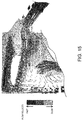
- Fig. 15 illustrates a result of a simulation of a flow of the cooling fluid which flows into the inner channel 7b (right side of Fig. 15 ) through the communicating holes 19 from the outer channel 7c (left side of Fig. 15 ).
- the magnitude and shade or depth of a vector indicates a speed of the flow velocity so that the flow velocity is faster as the magnitude of the vector becomes larger, while the flow velocity is faster as the shade is deeper.
- the shade is classified into three kinds so that they are easily distinguishable from each other.
- the cooling fluid which passed through the lower part of the communicating holes 19 contacted the lower part of the inlets 31c of the inter-bore channels 31 in the outer side surface of the cylinder bore wall 2a. Further, it is found that the cooling fluid which flows through the outer channel 7c upwardly turned smoothly to the communicating holes 19 side by the slope 16a (the same surface as the upper slope 19b) of the part of the lower surface of the upper flange 16 located above each communicating hole 19.
- the inner channel 7b and the outer channel 7c are partitioned by the peripheral wall 12, thereby fundamentally communicating with each other only at the communicating holes 19.
- the cooling fluid flows into the outer channel 7c from the cooling fluid inlet 8, and this cooling fluid flows through the outer channel 7c.
- Some of the cooling fluid flows into the inner channel 7b through the communicating holes 19, and some of the cooling fluid which inflowed then flows into the inlets 31c of the inter-bore channels 31.
- the cooling fluid which flowed into the inner channel 7b through the communicating holes 19 smoothly flows into the inlet 31c of the corresponding inter-bore channel 31 especially by the upper slope 19b of the inner circumferential surface of the communicating holes 19.
- the cooling fluid which did not flow into the inter-bore channels 31, of the cooling fluid which flowed into the inner channel 7b through the communicating holes 19 from the part of the outer channel 7c on the exhaust side flows toward the transmission as described above.
- the part of the cylinder bore wall 2a on the exhaust side which particularly gets hot can be cooled together with the necked parts 2b, thereby cooling the large area in the circumferential directions. Therefore, the cooling performance of the engine combustion chamber can be secured.
- the width of the inner channel 7b is less than the width of the outer channel 7c which communicates with the cooling fluid inlet 8, the cooling fluid is difficult to flow inside the inner channel.
- the cooling fluid which flowed into the inner channel 7b through the communicating holes 19 but did not flow into the inter-bore channels 31 is difficult to spread vertically in the inner channel 7b (in the cylinder bore axial directions), the cooling fluid fundamentally flows toward the transmission substantially at the same height as the communicating holes 19.
- the majority of the cooling fluid inside the inner channel 7b is stagnated, without being mixed with fresh cooling fluid. Therefore, the heat retention performance of the engine combustion chamber can be secured by the cooling fluid in the stagnated state.
- the upper part (cylinder head side) of the inner circumferential surface of the communicating hole 19 inclines toward the inlet 31c of the inter-bore channel 31 and the lower part (opposite side of the cylinder head) of the inner circumferential surface of the communicating hole 19 inclines toward the location below the inlet 31c of the inter-bore channel 31.
- the communicating hole 19 may have a cone shape of which the diameter decreases toward the inner channel 7b, and the entire inner circumferential surface of the communicating hole 19 may incline toward the inlet 31c of the inter-bore channel 31.
- the present disclosure may also be applied to a cooling structure of the engine mounted in the vehicle so that the cylinder bore axial directions are oriented horizontally.
- the present disclosure is applied to the multi-cylinder diesel engine, the present disclosure may suitably be applied to any type of multi-cylinder compression-ignition engine.
- the present disclosure is useful for the cooling structure of the engine, particularly the multi-cylinder engine, provided with the plurality of cylinder bores and the water jacket which surrounds the perimeter of the plurality of cylinder bores, the engine including the cylinder block in which the cylinder head is attached to the surface on a first side in the cylinder bore axial directions, the water jacket spacer which is accommodated in the water jacket of the cylinder block and having the peripheral wall formed corresponding to the plurality of cylinder bores.
- the present disclosure is particularly useful when the engine is the compression-ignition engine, such as the diesel engine.
Landscapes
- Engineering & Computer Science (AREA)
- Chemical & Material Sciences (AREA)
- Combustion & Propulsion (AREA)
- Mechanical Engineering (AREA)
- General Engineering & Computer Science (AREA)
- Cylinder Crankcases Of Internal Combustion Engines (AREA)
Description
- The present disclosure belongs to a technical field related to a cooling structure of an engine, particularly a multi-cylinder engine.
- Conventionally, as a cooling structure of an engine, particularly a multi-cylinder engine, for example, a structure is known in which a water jacket is formed in a cylinder block so as to surround the perimeter of a plurality of cylinder bores (a plurality of cylinder bore walls) and cooling fluid pumped by a water pump is introduced into the water jacket to cool an engine.
- Moreover, as disclosed in
JP2017-089563A JP2017-089563A - Meanwhile, in compression-ignition engines including diesel engines, it is necessary to keep combustion chambers of the engine warm in order to secure an environment for stabilizing compression ignition of fuel, i.e., in order to maintain the temperature of the combustion chambers at a temperature where compression ignition is possible. Further, it is necessary to cool the combustion chambers especially when the engine is operating at a high load.
- The water jacket spacer of
JP2017-089563A JP2017-089563A -
US 2005/217615 A1 discloses a cooling structure for cooling a bore wall of a cylinder block using a cooling medium. -
JP 2015 078675 A - The present disclosure is made in view of the situations described above, and it is to provide a cooling structure of an engine, which achieves securing both cooling performance and heat retention performance of the combustion chambers.
- In order to achieve the aforementioned purpose, according to one aspect of the present disclosure, a cooling structure of an engine is defined in
claim 1. - Particularly, the peripheral wall is configured to correspond to the plurality of cylinder bores.
- Further particularly, a length of the peripheral wall in cylinder bore axial directions is substantially the same as a length of the water jacket in the cylinder bore axial directions.
- Further particularly, the inter-bore channels is configured such that cooling fluid, particularly some of the cooling fluid, which flows from the outer channel into the inner channel through the communicating holes, flows into the inter-bore channels.
- Further particularly, a cooling fluid inlet, which is configured to communicate with the outer channel, is provided to the cylinder block.
- Further particularly, the cooling fluid inlet is configured such that the cooling fluid flows into the outer channel through the cooling fluid inlet.
- Further particularly, the engine is an in-series multi-cylinder engine. The engine may be an in-series 2-cylinder engine, an in-series 3-cylinder engine, an in-series 4-cylinder engine, an in-series 5-cylinder engine, or an in-series 6-cylinder engine.
- Further particularly, the cooling fluid inlet is configured to communicate with a part of the outer channel on a first side in cylinder line-up directions.
- Further particularly, a route, along which the cooling fluid flows, is configured such that the cooling fluid flows sequentially from the part of the outer channel on the first side, through a part on an exhaust side and a part on a second side in the cylinder line-up directions, and into a part on an intake side.
- Further particularly, the cooling fluid flows into the outer channel from the cooling fluid inlet and flows through the outer channel.
- Further particularly, a rib is formed in the part of an inner-channel-side surface of the peripheral wall on the first side.
- Further particularly, the rib is configured to disrupt the cooling fluid flowing in the circumferential directions in the part of the inner channel on the first side.
- According to an aspect of the invention, an engine is provided. The engine includes, a cylinder block, a plurality of cylinder bores formed in the cylinder block, a cylinder head, and the cooling structure as described above. Particularly, the cooling structure includes a water jacket configured to surround the plurality of cylinder bores, and a water jacket spacer accommodated in the water jacket of the cylinder block and having a peripheral wall.
- In order to achieve the aforementioned purpose, according to one aspect of the present disclosure, a cooling structure of a multi-cylinder engine having a cylinder block is provided, which includes a plurality of cylinder bores formed in the cylinder block, a water jacket surrounding the plurality of cylinder bores, a cylinder head, and a water jacket spacer accommodated in the water jacket of the cylinder block and having a peripheral wall formed to correspond to the plurality of cylinder bores. A length of the peripheral wall in cylinder bore axial directions is substantially the same as a length of the water jacket in the cylinder bore axial directions. The peripheral wall forms, inside the water jacket, an inner channel located inside the peripheral wall and an outer channel located outside the peripheral wall. A width of the inner channel is less than a width of the outer channel. Communicating holes communicating the inner channel with the outer channel are formed in the peripheral wall at locations between adjacent cylinder bores, respectively. Inter-bore channels into which some of cooling fluid flowing from the outer channel into the inner channel through the communicating holes flows are provided to parts of the cylinder block between the adjacent cylinder bores, respectively.
- According to this structure, since the length of the peripheral wall in the cylinder bore axial directions is substantially the same as the length of the water jacket in the cylinder bore axial directions, the inner channel and the outer channel are partitioned by the peripheral wall, thereby fundamentally communicating with each other only at the communicating holes. Further, when the cooling fluid is flowed into the water jacket from outside of the cylinder block, normally, the fluid is flowed into the outer channel which is located outside the peripheral wall. Although the cooling fluid may flow into both the outer and inner channels, since the width of the inner channel is less than the width of the outer channel, it is difficult for the cooling fluid to flow inside the inner channel. Thus, in the inner channel, it is difficult for fresh cooling fluid to flow and it is stagnated. Therefore, heat retention performance of the combustion chamber of the multi-cylinder engine can be secured by the cooling fluid in a stagnated state.
- On the other hand, in the outer channel, the cooling fluid can be flowed vigorously, and some of the cooling fluid flows into the inner channel through the communicating holes and some of the cooling fluid which inflowed then flows into the inter-bore channels. Especially by making at least a part of an inner circumferential surface of each communicating hole incline toward an inlet of a corresponding one of the inter-bore channels, a large amount of the cooling fluid which flowed into the inner channel through the communicating holes from the outer channel can be flowed into the inter-bore channels. Therefore, the cooling performance of the combustion chamber of the multi-cylinder engine can be secured, and the majority of the cooling fluid in the inner channel can be maintained in the stagnated state.
- Therefore, the cooling performance of the combustion chamber of the multi-cylinder engine can be secured, and the heat retention performance of the combustion chamber can be secured by the cooling fluid inside the inner channel.
- A part of the inner circumferential surface of each communicating hole on a cylinder head side inclines toward the inlet of the corresponding inter-bore channel. A part of the inner circumferential surface of each communicating hole on an opposite side of the cylinder head inclines toward a location below the inlet of the corresponding inter-bore channel.
- According to this, a large amount of the cooling fluid which flowed into the inner channel through the communicating holes from the outer channel can be flowed into the inter-bore channels, and a portion of the cooling fluid which flowed into the inner channel through the communicating holes can be assigned to the lower part of the inlets of the inter-bore channels in an outer side surface of a cylinder bore wall. As a result, the cylinder bore wall can also be cooled from the outer side surface.
- A cooling fluid inlet communicating with the outer channel may be provided to the cylinder block, the cooling fluid flowing into the outer channel cooling fluid inlet.
- According to this, the cooling fluid in the inner channel can be made into a more stagnated state. Further, the cooling fluid can be flowed vigorously from the outer channel to the inner channel through the communicating hole, and a large amount of the cooling fluid can be flowed into the inter-bore channel through the communicating hole.
- The multi-cylinder engine may be an in-series multi-cylinder engine. The cooling fluid inlet may communicate with a part of the outer channel on a first side in cylinder line-up directions. The cooling fluid flowing into the outer channel from the cooling fluid inlet and flowing through the outer channel may flow along a route sequentially from the part of the outer channel on the first side, through a part on an exhaust side and a part on a second side in the cylinder line-up directions, and into a part on an intake side. A rib configured to disrupt the cooling fluid flowing in the circumferential directions in the part of the inner channel on the first side in the cylinder line-up directions may be formed in the part of an inner-channel-side surface of the peripheral wall on the first side.
- According to this, the cooling fluid which did not flow into the inter-bore channels, of the cooling fluid which flowed into the inner channel through the communicating holes from the part of the outer channel on the exhaust side, does not flow toward the part formed with the rib in the inner channel, but instead flows to the second side in the cylinder line-up directions similar to the cooling fluid flowing in the outer channel on the exhaust side. As a result, the part of the cylinder bore wall on the exhaust side which gets particularly hot can be cooled over the large area in the circumferential directions, and the cooling performance of the combustion chamber of the multi-cylinder engine can further be secured. On the other hand, since the width of the inner channel is small as described above, the cooling fluid which did not flow into the inter-bore channels is difficult to spread in the cylinder bore axial directions of the inner channel, and basically, it flows toward the second side in the cylinder line-up directions at substantially the same location with the communicating holes in the cylinder bore axial directions. Therefore, the majority of the cooling fluid in the inner channel can be maintained in the stagnated state and the heat retention performance of the combustion chamber of the multi-cylinder engine can be secured.
-
-
Fig. 1 is a perspective view illustrating a cylinder block of a multi-cylinder engine to which a cooling structure according to one embodiment of the present disclosure is applied in a state where a water jacket spacer is accommodated in a block water jacket. -
Fig. 2 is a plan view of the cylinder block ofFig. 1 in which the water jacket spacer is accommodated in the block water jacket. -
Fig. 3 is a cross-sectional perspective view taken along a line III-III ofFig. 2 . -
Fig. 4 is a perspective view illustrating the water jacket spacer. -
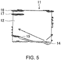
Fig. 5 is a view of the water jacket spacer when seen from the opposite side from a transmission. -
Fig. 6 is a view of the water jacket spacer when seen from the exhaust side. -
Fig. 7 is a view of the water jacket spacer when seen from the transmission side. -
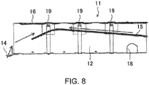
Fig. 8 is a view of the water jacket spacer when seen from the intake side. -
Fig. 9 is an enlarged plan view illustrating a necked part of a cylinder bore wall and an inwardly bent part of the block water jacket in an enlarged manner. -
Fig. 10 is a cross-sectional view taken along a line X-X ofFig. 2 . -
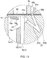
Fig. 11 is an enlarged cross-sectional view illustrating an XI part ofFig. 10 . -
Fig. 12 is a perspective view of a peripheral wall of the water jacket spacer, seen from a direction in which vertical ribs are visible. -
Fig. 13 is a cross-sectional view taken along a line XIII-XIII ofFig. 12 . -
Fig. 14 is a plan view illustrating a part of the water jacket spacer on the opposite side of the transmission. -
Fig. 15 is a view illustrating a result of a simulation of a flow of cooling fluid which flows into an inner channel through a communicating hole from an outer channel. - Hereinafter, one embodiment of the present disclosure is described in detail with reference to the accompanying drawings.
-
Figs. 1 and2 illustrate acylinder block 1 of an engine, particularly an multi-cylinder engine, to which a cooling structure according to one embodiment of the present disclosure is applied (hereinafter, simply referred to as "the engine"). In this embodiment, the engine is an in-line 4-cylinder diesel engine, having acylinder block 1 provided with fourcylinder bores 2 arranged in-line, and cylindrical-shapedcylinder bore walls 2a surrounding the perimeters of the cylinder bores 2, respectively. Adjacent cylinder borewalls 2a are integrally coupled to each other, and this type ofcylinder block 1 is called a Siamese cylinder block. A part of thecylinder bore walls 2a between the adjacent cylinder bores 2 is narrowed. The engine may be an in-line 2-cylinder diesel engine, an in-line 3-cylinder diesel engine, an in-line 4-cylinder diesel engine, an in-line 5-cylinder diesel engine, or an in-line 6-cylinder diesel engine. - In this embodiment, the engine is mounted in an engine bay located at a front part of a vehicle so that cylinder line-up directions are oriented in vehicle width directions and cylinder bore axial directions are oriented in vertical directions. A lower right side of
Fig. 1 and a lower side ofFig. 2 correspond to an intake side through which intake air is introduced into the engine, and an upper left side ofFig. 1 and an upper side ofFig. 2 correspond to an exhaust side through which exhaust gas is discharged from the engine. A transmission (not illustrated) is attached to an end face of thecylinder block 1 on the left side of the vehicle (right side ofFig. 2 ). In the following description, the engine shall be in a state where it is mounted in the vehicle. - In this embodiment, a heater plug-in
hole 3 into which a block heater (not illustrated) used in a cold region is inserted by a crew member is formed in a part in an intake-side surface of thecylinder block 1 on the transmission side. - As illustrated in
Fig. 10 , acylinder head 35 is attached to an upper surface of the cylinder block 1 (i.e., a surface of thecylinder block 1 on a first side in the cylinder bore axial directions) through agasket 36. Eight tappedholes 4 with which bolts (not illustrated) for attaching and fixing thecylinder head 35 to thecylinder block 1 threadedly engage are formed in the upper surface of thecylinder block 1. - The
cylinder block 1 is provided with ablock water jacket 7 which surrounds the perimeter of the four cylinder bores 2 (fourcylinder bore walls 2a). The number of the cylinder bores and the cylinder bore walls may be two, three, four, five, six or more. Theblock water jacket 7 is formed in a deep groove shape so as to open in the upper surface of thecylinder block 1. This opening is closed by thegasket 36 when thecylinder head 35 is attached to the upper surface of thecylinder lock 1 through thegasket 36. - A side wall inside the
block water jacket 7 is comprised of thecylinder bore walls 2a. A side wall surface inside theblock water jacket 7 is comprised of an outer side surface of the cylinder borewall 2a. Theblock water jacket 7 is curved inwardly so as to be closer to an imaginary central plane including all the centerlines of the four cylinder bores 2, corresponding to intake and exhaust side parts of thecylinder bore walls 2a between adjacent cylinder bores 2. Below, each of the intake and exhaust side parts of thecylinder bore walls 2a between the adjacent cylinder bores 2 is referred to as a "necked part 2b." Therefore, in this embodiment, a total of sixnecked parts 2b are formed in thecylinder bore walls 2a. - The
block water jacket 7 is provided, in a part thereof on the intake side and the opposite side of the transmission, with a coolingfluid introducing part 7a through which the cooling fluid is introduced into theblock water jacket 7. - A cooling
fluid inlet 8 through which the cooling fluid (e.g., engine cooling water or coolant) flows into theblock water jacket 7 is provided in a part of the intake-side surface of thecylinder block 1 on the opposite side of the transmission. The coolingfluid inlet 8 communicates with the coolingfluid introducing part 7a through a communicating channel 9 (seeFig. 3 ) having a rectangular cross-sectional shape provided in the intake-side wall part of thecylinder block 1. Thus, the coolingfluid inlet 8 communicates with the block water jacket 7 (in detail, with anouter channel 7c described below). The coolingfluid inlet 8 is connected with a discharge port of a water pump (not illustrated). Thus, the cooling fluid discharged from the discharge port of the water pump is introduced into the coolingfluid introducing part 7a through the coolingfluid inlet 8 and the communicatingchannel 9, and then flows into the block water jacket 7 (in detail, theouter channel 7c described below) from the coolingfluid introducing part 7a. - As illustrated in
Fig. 3 , the communicatingchannel 9 opens in the outer side-wall surface of the block water jacket 7 (in detail, the side wall surface of the coolingfluid introducing part 7a). A lower surface of the opening is located higher than a bottom surface of the coolingfluid introducing part 7a, thereby producing a stepped part between the lower surface of the opening and the bottom surface of the coolingfluid introducing part 7a. The stepped part is produced because of a directional difference of removing molds between a mold for the communicating channel 9 (removed toward the cooling fluid inlet 8) and a mold for the block water jacket 7 (removed upwardly) when casting thecylinder block 1. - As illustrated in
Figs. 4 to 11 , awater jacket spacer 11 having aperipheral wall 12 formed corresponding to the cylinder bores 2 (cylinder bore walls 2a), particularly the four cylinder bores 2 (fourcylinder bore walls 2a), is accommodated in theblock water jacket 7. Thewater jacket spacer 11 is made particularly of resin. The height of the peripheral wall 12 (i.e., a length in the cylinder bore axial directions) corresponds to or is substantially the same as a groove depth of the block water jacket 7 (i.e., a length in the cylinder bore axial directions). In this embodiment, theperipheral wall 12 of thewater jacket spacer 11 has cylindrical shapes surrounding the four cylinder bores 2 (fourcylinder bore walls 2a). Note that theperipheral wall 12 may be partially separated or divided in circumferential directions. - The
water jacket spacer 11 is constructed by theperipheral wall 12 of thewater jacket spacer 11 so that aninner channel 7b located inside the peripheral wall 12 (on the cylinder borewall 2a side) and anouter channel 7c located outside the peripheral wall 12 (on the opposite side from the cylinder borewall 2a) are formed in the water jacket 7 (particularly, seeFig. 10 ). A width of theinner channel 7b (a distance between the inner surface of theperipheral wall 12 and the inner side-wall surface of the water jacket 7) is less than a width of theouter channel 7c (a distance between the outer surface of theperipheral wall 12 and the outer side-wall surface of the water jacket 7). Theperipheral wall 12 of thewater jacket spacer 11 has, similar to thewater jacket 7, six inwardlybent parts 13 which curve inwardly so as to be closer to the central plane described above corresponding to the sixnecked parts 2b of the cylinder borewall 2a, respectively. - An
extended part 14 extending so as to cover the bottom surface of the coolingfluid introducing part 7a from above is provided in a part of a lower end part of theperipheral wall 12 of thewater jacket spacer 11 corresponding to the coolingfluid introducing part 7a. An upper surface of theextended part 14 is located at the same height as the lower surface of the opening of the communicatingchannel 9 described above so that the stepped part described above is eliminated by theextended part 14. If the stepped part remains, this stepped part disrupts the flow of the cooling fluid introduced into the coolingfluid introducing part 7a from the communicatingchannel 9. On the other hand, by theextended part 14 eliminating the stepped part, the disruption of the cooling fluid flow is controlled. - The cooling
fluid introducing part 7a extends, in the plan view, obliquely to the exhaust side toward the transmission. A downstream end of the coolingfluid introducing part 7a is connected to the part of theouter channel 7c on the opposite side of the transmission. Thus, the coolingfluid inlet 8 is a cooling fluid inlet into theouter channel 7c, and communicates with the part of theouter channel 7c on the opposite side of the transmission (a part on first side in the cylinder line-up directions). As illustrated inFigs. 4 and5 , the inclination of the coolingfluid introducing part 7a described above causes a majority of the cooling fluid which flowed into theouter channel 7c from the coolingfluid introducing part 7a to flow to the exhaust side along the outer surface of the part of theperipheral wall 12 of thewater jacket spacer 11 on the opposite side of the transmission. The remaining portion of the cooling fluid flows to the transmission side along the outer surface of the intake-side part of the peripheral wall 12 (see arrows inFigs. 4 and5 ). - Although illustration is omitted, an inflow hole, which the cooling fluid flows through a part of the
outer channel 7c on the opposite side of the transmission flows into ahead water jacket 35a (seeFig. 10 ) in thecylinder head 35, is formed in an end part of thecylinder head 35 and an end part of thegasket 36 on the opposite side of the transmission, respectively. The inflow holes of thecylinder head 35 and thegasket 36 are located above the part of theouter channel 7c on the opposite side of the transmission, and vertically communicate theouter channel 7c with thehead water jacket 35a. - Since the cooling fluid immediately after flowing into the
outer channel 7c from the coolingfluid introducing part 7a and then flowing to the exhaust side has just been discharged from the discharge port of the water pump, the flow is strong, thereby the cooling fluid flows strongly vertically upward. Thus, some of the cooling fluid which flows to the exhaust side passes through the inflow hole and then flows into an end part (on the opposite side of the transmission) of thehead water jacket 35a which extends in the cylinder line-up directions. The cooling fluid which did not flow into the inflow hole flows inside theouter channel 7c through the part on the opposite side of the transmission, the part on the exhaust side, the part on the transmission side, and the part on the intake side in this order so that it substantially circles theouter channel 7c (see arrows inFigs. 6 to 8 ). That is, the route of the cooling fluid which flows into theouter channel 7c from the coolingfluid inlet 8 and then flows through theouter channel 7c is fundamentally a route where the cooling fluid flows from the part of theouter channel 7c on the opposite side of the transmission (the part on the first side in the cylinder line-up directions described above), then passes through the part on the exhaust side and the part on the transmission side (the part on the second side in the cylinder line-up directions), then flows into the part on the intake side. The cooling fluid which flows through theouter channel 7c flows, in the plan view, in a substantially U-shape. - A cooling
fluid guide slope 15 for lifting the cooling fluid upwardly as it goes to the downstream side of theouter channel 7c is formed so as to protrude from the outer surface of theperipheral wall 12 of the water jacket spacer 11 (the surface on theouter channel 7c side). As illustrated inFig. 5 , the coolingfluid guide slope 15 extends in the part of theperipheral wall 12 on the opposite side of the transmission, from a base-end part of theextended part 14 to the exhaust side, and then inclines upwardly to the exhaust side from an intermediate location thereof. In the part of theperipheral wall 12 on the exhaust side, as illustrated inFig. 6 , the coolingfluid guide slope 15 inclines upwardly to the transmission side so as to be continuous to the part of theperipheral wall 12 on the opposite side of the transmission. In the part of theperipheral wall 12 on the transmission side, as illustrated inFig. 7 , the coolingfluid guide slope 15 inclines upwardly to the intake side so as to be continuous to the part of theperipheral wall 12 on the exhaust side. In the part of theperipheral wall 12 on the intake side, as illustrated inFig. 8 , the coolingfluid guide slope 15 inclines upwardly to the opposite side of the transmission so as to be continuous to the part of theperipheral wall 12 on the transmission side. Note that the coolingfluid guide slope 15 in the part of theperipheral wall 12 on the intake side inclines downwardly to the opposite side of the transmission, in a section on the opposite side of the transmission from a position corresponding to the second cylinder bore 2 to the opposite side of the transmission. This is to lift upwardly the cooling fluid which flowed into theouter channel 7c from the coolingfluid introducing part 7a and which flows toward the transmission (see an arrow to the right side inFig. 8 ). - The cooling fluid which substantially circled the
outer channel 7c, and the cooling fluid which flowed into theouter channel 7c from the coolingfluid introducing part 7a and flowed toward the transmission flow into an oil cooler (not illustrated) from a cooling fluid outlet 5 (seeFig. 1 ) provided to a side wall surface on the intake side of thecylinder block 1. - As will be described in detail later, the cooling fluid, particularly some of the cooling fluid, which flows through the
outer channel 7c, flows into theinner channel 7b through communicatingholes 19, particularly six communicatingholes 19, described below, and then flows from theinner channel 7b throughinter-bore channels 31, particularly sixinter-bore channels 31, described below into thehead water jacket 35a. The number of the communicating holes may be two, four, six, eight, ten or more. The number of the inter-bore channels may be two, four, six, eight, ten or more. - The cooling fluid, which flowed into the
head water jacket 35a from the inflow hole described above, flows through the inside of thehead water jacket 35a from the opposite side of the transmission to the transmission side, and then joins at an intermediate location with the cooling fluid which flowed into thehead water jacket 35a through theinter-bore channels 31. The cooling fluid joined as described above flows outside thecylinder head 35 from an outlet provided to an end face of thecylinder head 35 on the transmission side. The cooling fluid which flowed out from the outlet and the cooling fluid which passed through the oil cooler then pass through a radiator, and are then sucked into a suction port of the water pump. - An
upper flange 16 which protrudes outwardly from theperipheral wall 12 of the water jacket spacer 11 (i.e., protrudes into theouter channel 7c) is formed in an upper end in the outer surface of theperipheral wall 12. Theupper flange 16 is formed substantially entirely in the circumferential directions of theperipheral wall 12 except for a part on the opposite side of the transmission (a part corresponding to the inflow hole). Theupper flange 16 prevents the cooling fluid which flows through theouter channel 7c from flowing into theinner channel 7b beyond the upper end of theperipheral wall 12. - Moreover, as illustrated in
Figs. 5 and6 , alower flange 17 extending in the circumferential directions of theperipheral wall 12 is formed substantially parallel to theupper flange 16, in a part of the outer surface of theperipheral wall 12 in the circumferential directions so that thelower flange 17 is separated downwardly from theupper flange 16 by a given interval. Thelower flange 17 is formed in a part corresponding to the upstream side of theouter channel 7c in the circumferential directions of theperipheral wall 12 except for the part corresponding to the inflow hole. That is, since the cooling fluid flows vigorously upward in the upstream part of theouter channel 7c as described above, the double flange comprised of theupper flange 16 and thelower flange 17 prevents the cooling fluid from flowing into theinner channel 7b beyond the upper end of theperipheral wall 12. Note thatnotches 17a are formed in thelower flange 17 at locations immediately below the communicatingholes 19 described below so that the cooling fluid flows into the communicating holes 19. - As illustrated in
Figs. 4 and8 , anotch 18 for avoiding interference with the block heater inserted into the heater plug-inhole 3 is formed in a lower part of theperipheral wall 12 on the intake side and the transmission side. - As illustrated in
Figs. 4 ,6 , and8 to 11 , the communicating holes 19 (in this embodiment, total of six communicating holes 19) which communicates theinner channel 7b with theouter channel 7c are formed in theperipheral wall 12 of thewater jacket spacer 11 at locations corresponding to the sixnecked parts 2b of the cylinder borewall 2a (i.e., the six inwardly bent parts 13), respectively. These communicatingholes 19 are formed near the upper end of the peripheral wall 12 (near the end part on thecylinder head 35 side). Some of the cooling fluid which flows through theouter channel 7c flows into theinner channel 7b through the communicating holes 19. - Each communicating
hole 19 is formed in a vertically-elongated rectangular shape in the cross section. That is, the vertical length of the communicatinghole 19 is greater than the lateral width (the length in the cylinder line-up directions) of the communicatinghole 19. - As illustrated in
Figs. 10 and11 , theinter-bore channels 31 are provided to thenecked parts 2b of the cylinder borewall 2a, respectively. - The
inter-bore channel 31 of eachnecked part 2b is comprised of anupstream channel 31a and adownstream channel 31b, and an upper end of thedownstream channel 31b is connected to a downstream end of theupstream channel 31a. An upper end of theupstream channel 31a has a larger diameter than other parts of theupstream channel 31a, and opens to the inner side-wall surface of thewater jacket 7. This opening of the inner side-wall surface of theupstream channel 31a corresponds toinlets 31c of theinter-bore channels 31. A downstream end of thedownstream channel 31b opens to the upper surface of the cylinder borewall 2a. This opening of thedownstream channel 31b formed in the upper surface of thecylinder block 1 corresponds tooutlets 31d of theinter-bore channels 31. - Both the
upstream channel 31a and thedownstream channel 31b extend toward the central plane and incline downwardly. The inclination angle of theupstream channel 31a which has a more acute angle with respect to a horizontal plane is smaller than the inclination angle of thedownstream channel 31b which has a more acute angle with respect to a horizontal plane. Both theupstream channel 31a and thedownstream channel 31b may be formed by drilling. - The downstream end of the
downstream channel 31b (the opening in the upper surface of the cylinder block 1) is connected to thehead water jacket 35a of thecylinder head 35 through in connectingholes 36a formed in thegasket 36 and connectingchannels 35b formed in thecylinder head 35. - Each communicating
hole 19 is located at the same position as aninlet 31c of theinter-bore channel 31 of the correspondingnecked part 2b in the cylinder line-up directions. Thus, some of the cooling fluid which flowed into theinner channel 7b from theouter channel 7c through the corresponding communicatinghole 19 flows into eachinter-bore channel 31. - That is, a part of the inner circumferential surface of each communicating
hole 19 in the circumferential directions inclines toward theinlet 31c of the correspondinginter-bore channel 31. For example, as illustrated inFig. 11 , an upper part (cylinder head side) of the inner circumferential surface of each communicatinghole 19 is anupper slope 19b which inclines toward theinlet 31c of the correspondinginter-bore channel 31. Theupper slope 19b inclines downwardly as it goes toward theinner channel 7b. Thus, some of the cooling fluid which flowed into theinner channel 7b through each communicatinghole 19 flows smoothly into theinlet 31c of the correspondinginter-bore channel 31. Note that aslope 16a which inclines so as to be a flush surface with theupper slope 19b is formed in a part of the lower surface of theupper flange 16 located above each communicatinghole 19. - In this embodiment, the lower part of the inner circumferential surface of each communicating hole 19 (opposite side of the cylinder head) is a
lower slope 19a which inclines toward a location below theinlet 31c of theinter-bore channel 31. Thelower slope 19a inclines so as to be located higher as it goes toward theinner channel 7b. Thus, some of the cooling fluid which flowed into theinner channel 7b from theouter channel 7c through the communicatingholes 19 is assigned to the lower parts of theinlets 31c of theinter-bore channels 31 in the outer side surface of the cylinder borewall 2a to cool the cylinder borewall 2a from the outer side surface. In addition, in this embodiment, since the vertical length of each communicatinghole 19 is greater than the lateral width of the communicatinghole 19, the largest possible range in thenecked parts 2b of the cylinder borewall 2a in the vertical directions can be cooled. Moreover, since the lateral width of each communicatinghole 19 is made smaller, a flow velocity of the cooling fluid can be increased as much as possible to make the cooling fluid vigorously hit thenecked parts 2b of the cylinder borewall 2a, but theupper slope 19b can cause the cooling fluid to flow more smoothly into theinlets 31c of theinter-bore channels 31. - The cooling fluid which flowed into the
inlets 31c of theinter-bore channels 31 flows through theupstream channel 31a and thedownstream channel 31b in this order so that it is sucked to thecylinder head 35 side. Thus, thenecked parts 2b of the cylinder borewall 2a are further cooled from the inside of the wall. Then, the cooling fluid exits from theoutlets 31d of theinter-bore channels 31, and flows into thehead water jacket 35a through the connectingholes 36a of thegasket 36 and the connectingchannels 35b of thecylinder head 35. - In this embodiment, as illustrated in
Figs. 12 to 14 , a plurality ofvertical ribs 23, which disrupts the cooling fluid flowing in the circumferential directions in the part of theinner channel 7b on the opposite side of the transmission (the part on the first side in the cylinder line-up directions), are formed in a part of the inner surface (theinner channel 7b side) of theperipheral wall 12 of thewater jacket spacer 11 on the opposite side of the transmission (the part on the first side in the cylinder line-up directions) so as to be apart from each other in the circumferential directions. Thevertical ribs 23 are formed entirely in the height directions of theperipheral wall 12. A width of theinner channel 7b in the part where thevertical ribs 23 are formed (the distance between thevertical ribs 23 and the inner side-wall surface of the water jacket 7) is less than a width of theinner channel 7b in the part where thevertical ribs 23 are not formed. - Adjacent
vertical ribs 23 are coupled to each other with alateral rib 24 provided in an upper part of the inner surface of theperipheral wall 12. As illustrated inFig. 13 , the interval of the adjacent vertical ribs 23 (a part below the lateral ribs 24) are larger as it goes lower (and the width of thevertical rib 23 is narrower as it goes to lower). Thus, when fabricating thewater jacket spacer 11 by injection molding, it is easier to downwardly remove a mold for fabricating the vertical ribs 23 (the part below the lateral ribs 24). - As illustrated in
Fig. 14 , the formed range of thevertical ribs 23 is, in the plan view, a range including the base-end part of the extended part 14 (the downstream end of the coolingfluid introducing part 7a) in the part of the inner surface of theperipheral wall 12 on the opposite side of the transmission. The formed range of thevertical ribs 23 is, in the plan view, for example, 60° or larger and 120° or smaller as an angle about a center O of the first cylinder bore 2 from the opposite side of the transmission. Since theextended part 14 is located closer to the intake side in the part of the inner surface of theperipheral wall 12 on the opposite side of the transmission, the formed range of thevertical ribs 23 is also located closer to the intake side with respect to the central plane (represented by C inFig. 14 ). - The
upper flange 16 is not formed in parts corresponding to the formed range of thevertical ribs 23 in the outer surface of theperipheral wall 12 except for the twovertical ribs 23 located at both ends in the circumferential directions. Therefore, the possibility that the cooling fluid from the coolingfluid introducing part 7a flows into theinner channel 7b beyond the upper end of theperipheral wall 12 might be high. However, in this embodiment, the twovertical ribs 23 located at the both ends in the circumferential directions prevent that the cooling fluid which flowed into theinner channel 7b beyond the upper end of theperipheral wall 12 flows to the transmission side. - The plurality of
vertical ribs 23 make the cooling fluid which did not flow into theinter-bore channels 31, of the cooling fluid which flowed into theinner channel 7b through the communicatingholes 19 from the part of theouter channel 7c on the exhaust side, flow to the transmission side without flowing to the side where thevertical ribs 23 are formed (the opposite side of the transmission), similar to the cooling fluid which flows through the part of theouter channel 7c on the exhaust side. Note that the cooling fluid which did not flow into theinter-bore channels 31, of the cooling fluid which flowed into theinner channel 7b through the communicatingholes 19 from the intake-side part of theouter channel 7c, will neither flow into the opposite side of the transmission where thevertical ribs 23 are formed, nor flow to the transmission side because of the cooling fluid flowing through theinner channel 7b from the exhaust side, thereby being pushed into theinter-bore channels 31. -
Fig. 15 illustrates a result of a simulation of a flow of the cooling fluid which flows into theinner channel 7b (right side ofFig. 15 ) through the communicatingholes 19 from theouter channel 7c (left side ofFig. 15 ). The magnitude and shade or depth of a vector indicates a speed of the flow velocity so that the flow velocity is faster as the magnitude of the vector becomes larger, while the flow velocity is faster as the shade is deeper. Here, the shade is classified into three kinds so that they are easily distinguishable from each other. - From the result of the simulation, it is found that the cooling fluid which passed through the upper part of the communicating
holes 19 among the cooling fluid which flowed into theinner channel 7b through the communicatingholes 19 from theouter channel 7c flowed toward theinlets 31c (indicated on the right side of theinner channel 7b inFig. 15 ) of theinter-bore channels 31 due to theupper slope 19b, and flowed into theinlets 31c. Since the cooling fluid which flowed into theinlets 31c of theinter-bore channels 31 was sucked to thecylinder head 35 side, the flow velocity became faster. Moreover, it is found that the cooling fluid which passed through the lower part of the communicatingholes 19 contacted the lower part of theinlets 31c of theinter-bore channels 31 in the outer side surface of the cylinder borewall 2a. Further, it is found that the cooling fluid which flows through theouter channel 7c upwardly turned smoothly to the communicatingholes 19 side by theslope 16a (the same surface as theupper slope 19b) of the part of the lower surface of theupper flange 16 located above each communicatinghole 19. - Therefore, in this embodiment, since the height of the
peripheral wall 12 of the water jacket spacer 11 (the length in the cylinder bore axial directions) is substantially the same as the groove depth of the block water jacket 7 (the length in the cylinder bore axial directions), theinner channel 7b and theouter channel 7c are partitioned by theperipheral wall 12, thereby fundamentally communicating with each other only at the communicating holes 19. Thus, the cooling fluid flows into theouter channel 7c from the coolingfluid inlet 8, and this cooling fluid flows through theouter channel 7c. Some of the cooling fluid flows into theinner channel 7b through the communicatingholes 19, and some of the cooling fluid which inflowed then flows into theinlets 31c of theinter-bore channels 31. Some of the cooling fluid which flowed into theinner channel 7b through the communicatingholes 19 smoothly flows into theinlet 31c of the correspondinginter-bore channel 31 especially by theupper slope 19b of the inner circumferential surface of the communicating holes 19. Moreover, the cooling fluid which did not flow into theinter-bore channels 31, of the cooling fluid which flowed into theinner channel 7b through the communicatingholes 19 from the part of theouter channel 7c on the exhaust side, flows toward the transmission as described above. As a result, the part of the cylinder borewall 2a on the exhaust side which particularly gets hot can be cooled together with thenecked parts 2b, thereby cooling the large area in the circumferential directions. Therefore, the cooling performance of the engine combustion chamber can be secured. - Moreover, since the width of the
inner channel 7b is less than the width of theouter channel 7c which communicates with the coolingfluid inlet 8, the cooling fluid is difficult to flow inside the inner channel. Thus, the cooling fluid which flowed into theinner channel 7b through the communicatingholes 19 but did not flow into theinter-bore channels 31 is difficult to spread vertically in theinner channel 7b (in the cylinder bore axial directions), the cooling fluid fundamentally flows toward the transmission substantially at the same height as the communicating holes 19. As a result, the majority of the cooling fluid inside theinner channel 7b is stagnated, without being mixed with fresh cooling fluid. Therefore, the heat retention performance of the engine combustion chamber can be secured by the cooling fluid in the stagnated state. - The present disclosure is not limited to the embodiment described above, and it may be substituted without departing from the subject matter of the appended claims.
- For example, although in the above embodiment the upper part (cylinder head side) of the inner circumferential surface of the communicating
hole 19 inclines toward theinlet 31c of theinter-bore channel 31 and the lower part (opposite side of the cylinder head) of the inner circumferential surface of the communicatinghole 19 inclines toward the location below theinlet 31c of theinter-bore channel 31. Moreover, the communicatinghole 19 may have a cone shape of which the diameter decreases toward theinner channel 7b, and the entire inner circumferential surface of the communicatinghole 19 may incline toward theinlet 31c of theinter-bore channel 31. - Moreover, although in the above embodiment the engine is mounted in the vehicle so that the cylinder bore axial directions are oriented in the vertical directions, the present disclosure may also be applied to a cooling structure of the engine mounted in the vehicle so that the cylinder bore axial directions are oriented horizontally.
- Moreover, although in the above embodiment the present disclosure is applied to the multi-cylinder diesel engine, the present disclosure may suitably be applied to any type of multi-cylinder compression-ignition engine.
- The embodiment described above is merely illustration, and is not to be interpreted as limiting the scope of the present disclosure. The scope of the present disclosure is defined by the appended claims, and all modifications and changes which fall within the range of the claims are within the scope of the present disclosure.
- The present disclosure is useful for the cooling structure of the engine, particularly the multi-cylinder engine, provided with the plurality of cylinder bores and the water jacket which surrounds the perimeter of the plurality of cylinder bores, the engine including the cylinder block in which the cylinder head is attached to the surface on a first side in the cylinder bore axial directions, the water jacket spacer which is accommodated in the water jacket of the cylinder block and having the peripheral wall formed corresponding to the plurality of cylinder bores. The present disclosure is particularly useful when the engine is the compression-ignition engine, such as the diesel engine.
-
- 1
- Cylinder Block
- 2
- Cylinder Bore
- 7
- Block Water Jacket
- 7b
- Inner Channel
- 7c
- Outer Channel
- 8
- Cooling Fluid Inlet
- 11
- Water Jacket Spacer
- 12
- Peripheral Wall
- 19
- Communicating Hole
- 19a
- Lower Slope
- 19b
- Upper Slope
- 23
- Vertical Rib
- 35
- Cylinder Head
Claims (12)
- A cooling structure of an engine having a cylinder block (1), a plurality of cylinder bores (2) formed in the cylinder block (1), and a cylinder head (35), the cooling structure comprising:a water jacket (7) configured to surround the plurality of cylinder bores (2); anda water jacket spacer (11) accommodated in the water jacket (7) and having a peripheral wall (12),wherein the peripheral wall (12) is configured to form, inside the water jacket (7), an inner channel (7b) located inside the peripheral wall (12) and an outer channel (7c) located outside the peripheral wall (12),wherein a width of the inner channel (7b) is less than a width of the outer channel (7c),wherein communicating holes (19), which are configured to communicate the inner channel (7b) with the outer channel (7c), are formed in the peripheral wall (12) at locations between adjacent cylinder bores (2), respectively, andwherein inter-bore channels (31) are provided to parts of the cylinder block (1) between the adjacent cylinder bores (2), respectively,characterized in thata vertical length of the communicating hole (19) is greater than a lateral width of the communicating hole (19),a lower part of an inner circumferential surface of the communicating hole (19) is below an inlet (31c) of the inter-bore channel (31),a part (19b) of the inner circumferential surface of each communicating hole (19) on a cylinder head side inclines toward the inlet (31c) of the corresponding inter-bore channel (31), anda part (19a) of the inner circumferential surface of each communicating hole (19) on an opposite side of the cylinder head (35) inclines toward a location below the inlet (31c) of the corresponding inter-bore channel (31).
- The cooling structure of claim 1, wherein the peripheral wall (12) is configured to correspond to the plurality of cylinder bores (2).
- The cooling structure of claim 1 or 2, wherein a length of the peripheral wall (12) in cylinder bore axial directions is substantially the same as a length of the water jacket (7) in the cylinder bore axial directions.
- The cooling structure of any one of claims 1 to 3, wherein the inter-bore channels (31) is configured such that cooling fluid, particularly some of the cooling fluid, which flows from the outer channel (7c) into the inner channel (7b) through the communicating holes (19), flows into the inter-bore channels (31).
- The cooling structure of any one of claims 1 to 4, wherein a cooling fluid inlet (8), which is configured to communicate with the outer channel (7c), is provided to the cylinder block (1).
- The cooling structure of claim 5, wherein the cooling fluid inlet (8) is configured such that the cooling fluid flows into the outer channel (7c) through the cooling fluid inlet (8).
- The cooling structure of claim 5 or 6, wherein the engine is an in-series multi-cylinder engine,
wherein the cooling fluid inlet (8) is configured to communicate with a part of the outer channel (7c) on a first side in cylinder line-up directions. - The cooling structure of claim 1, wherein a route, along which the cooling fluid flows, is configured such that the cooling fluid flows sequentially from the part of the outer channel (7c) on the first side, through a part on an exhaust side and a part on a second side in the cylinder line-up directions, and into a part on an intake side.
- The cooling structure of claim 8, wherein the cooling fluid flows into the outer channel (7c) from the cooling fluid inlet (8) and flows through the outer channel (7c).
- The cooling structure of any one of claims 7 to 9, wherein a rib (23) is formed in the part of an inner-channel-side surface of the peripheral wall (12) on the first side.
- The cooling structure of claim 10, wherein the rib (23) is configured to disrupt the cooling fluid flowing in the circumferential directions in the part of the inner channel (7b) on the first side.
- An Engine comprising:a cylinder block (1);a plurality of cylinder bores (2) formed in the cylinder block (1);a cylinder head (35); andthe cooling structure according to any one of claims 1 to 11.
Applications Claiming Priority (1)
| Application Number | Priority Date | Filing Date | Title |
|---|---|---|---|
| JP2017198992A JP6575578B2 (en) | 2017-10-13 | 2017-10-13 | Multi-cylinder engine cooling structure |
Publications (2)
| Publication Number | Publication Date |
|---|---|
| EP3470654A1 EP3470654A1 (en) | 2019-04-17 |
| EP3470654B1 true EP3470654B1 (en) | 2021-10-06 |
Family
ID=63798866
Family Applications (1)
| Application Number | Title | Priority Date | Filing Date |
|---|---|---|---|
| EP18199235.5A Active EP3470654B1 (en) | 2017-10-13 | 2018-10-09 | Cooling structure of engine |
Country Status (3)
| Country | Link |
|---|---|
| US (1) | US10612448B2 (en) |
| EP (1) | EP3470654B1 (en) |
| JP (1) | JP6575578B2 (en) |
Families Citing this family (8)
| Publication number | Priority date | Publication date | Assignee | Title |
|---|---|---|---|---|
| JP6919800B2 (en) * | 2017-02-15 | 2021-08-18 | ニチアス株式会社 | Water jacket spacer |
| JP7352170B2 (en) * | 2019-11-18 | 2023-09-28 | マツダ株式会社 | Engine cooling structure |
| CN111878246A (en) * | 2020-03-02 | 2020-11-03 | 广西玉柴机器股份有限公司 | Water inlet and return structure of cylinder body |
| JP7449562B2 (en) * | 2020-06-18 | 2024-03-14 | 内山工業株式会社 | Spacer and spacer assembly method |
| USD1024133S1 (en) * | 2020-06-24 | 2024-04-23 | Caterpillar Inc. | Cylinder head |
| US11378036B2 (en) * | 2020-10-01 | 2022-07-05 | Ford Global Technologies, Llc | Bore bridge cooling channels |
| CN116696585B (en) * | 2023-06-12 | 2026-02-17 | 浙江美可达摩托车有限公司 | A cooling structure for an engine |
| CN116624285B (en) * | 2023-06-12 | 2026-02-17 | 浙江美可达摩托车有限公司 | A cooling water circuit structure for an engine |
Family Cites Families (14)
| Publication number | Priority date | Publication date | Assignee | Title |
|---|---|---|---|---|
| JP4279714B2 (en) * | 2004-03-31 | 2009-06-17 | トヨタ自動車株式会社 | Cylinder block cooling structure |
| JP2006090197A (en) * | 2004-09-22 | 2006-04-06 | Aisan Ind Co Ltd | Cooling device for internal combustion engine |
| JP2007321581A (en) * | 2006-05-30 | 2007-12-13 | Toyota Motor Corp | Cylinder block |
| JP4845620B2 (en) * | 2006-07-21 | 2011-12-28 | トヨタ自動車株式会社 | Heat medium passage partition member for cooling internal combustion engine, internal combustion engine cooling structure, and internal combustion engine cooling structure forming method |
| JP5610290B2 (en) * | 2010-11-29 | 2014-10-22 | 内山工業株式会社 | Water jacket spacer |
| JP6415806B2 (en) * | 2013-10-18 | 2018-10-31 | マツダ株式会社 | Engine cooling system |
| JP6052135B2 (en) * | 2013-10-25 | 2016-12-27 | マツダ株式会社 | Engine cooling system |
| JP6056741B2 (en) * | 2013-12-05 | 2017-01-11 | マツダ株式会社 | Multi-cylinder engine cooling system |
| JP6176188B2 (en) * | 2014-05-30 | 2017-08-09 | マツダ株式会社 | Multi-cylinder engine cooling structure |
| US9470176B2 (en) * | 2014-08-01 | 2016-10-18 | Ford Global Technologies, Llc | Bore bridge and cylinder cooling |
| US9670822B2 (en) * | 2014-09-08 | 2017-06-06 | Ford Global Technologies, Llc | Bore bridge and cylinder cooling |
| JP6225971B2 (en) * | 2015-09-30 | 2017-11-08 | マツダ株式会社 | Cylinder body structure of multi-cylinder engine |
| JP6718222B2 (en) | 2015-11-13 | 2020-07-08 | ダイハツ工業株式会社 | Internal combustion engine |
| JP6315022B2 (en) * | 2016-04-19 | 2018-04-25 | マツダ株式会社 | Multi-cylinder engine cooling structure |
-
2017
- 2017-10-13 JP JP2017198992A patent/JP6575578B2/en active Active
-
2018
- 2018-09-12 US US16/128,791 patent/US10612448B2/en not_active Expired - Fee Related
- 2018-10-09 EP EP18199235.5A patent/EP3470654B1/en active Active
Non-Patent Citations (1)
| Title |
|---|
| None * |
Also Published As
| Publication number | Publication date |
|---|---|
| JP6575578B2 (en) | 2019-09-18 |
| US20190112963A1 (en) | 2019-04-18 |
| EP3470654A1 (en) | 2019-04-17 |
| US10612448B2 (en) | 2020-04-07 |
| JP2019073990A (en) | 2019-05-16 |
Similar Documents
| Publication | Publication Date | Title |
|---|---|---|
| US10612448B2 (en) | Cooling structure of multi-cylinder engine | |
| US8960137B2 (en) | Integrated exhaust cylinder head | |
| CN105275655B (en) | The cooling construction of multiple cylinder engine | |
| JP6299737B2 (en) | Multi-cylinder engine cooling structure | |
| US10107171B2 (en) | Cooling structure of internal combustion engine | |
| US20120312257A1 (en) | Integrated exhaust cylinder head | |
| JP6384492B2 (en) | Multi-cylinder engine cooling structure | |
| JP5939176B2 (en) | Multi-cylinder engine cooling structure | |
| CN110366636B (en) | Cylinder head for an internal combustion engine | |
| KR101776756B1 (en) | Engine having water jacket | |
| US6962131B2 (en) | Water cooling device of vertical multi-cylinder engine | |
| JP2007127066A (en) | Internal combustion engine cooling structure and water channel forming member | |
| EP3034846A1 (en) | Cylinder block | |
| JP6358284B2 (en) | Engine cooling structure | |
| CN109653893B (en) | Cooling jacket for cylinder head | |
| JP6314966B2 (en) | Multi-cylinder engine cooling structure | |
| US10914208B2 (en) | In-vehicle internal combustion engine | |
| RU2602722C1 (en) | Gas line for recirculation of exhaust gases | |
| JP2011208527A (en) | Cooling structure of internal combustion engine | |
| JP7327684B2 (en) | Cooling structure of internal combustion engine | |
| US9879634B2 (en) | Engine block for an internal combustion engine | |
| JP6985679B2 (en) | Multi-cylinder engine cooling structure | |
| JP3885260B2 (en) | Engine cooling system | |
| KR101755876B1 (en) | A engine block of vehicle | |
| JP2012017654A (en) | Internal combustion engine |
Legal Events
| Date | Code | Title | Description |
|---|---|---|---|
| PUAI | Public reference made under article 153(3) epc to a published international application that has entered the european phase |
Free format text: ORIGINAL CODE: 0009012 |
|
| STAA | Information on the status of an ep patent application or granted ep patent |
Free format text: STATUS: THE APPLICATION HAS BEEN PUBLISHED |
|
| AK | Designated contracting states |
Kind code of ref document: A1 Designated state(s): AL AT BE BG CH CY CZ DE DK EE ES FI FR GB GR HR HU IE IS IT LI LT LU LV MC MK MT NL NO PL PT RO RS SE SI SK SM TR |
|
| AX | Request for extension of the european patent |
Extension state: BA ME |
|
| STAA | Information on the status of an ep patent application or granted ep patent |
Free format text: STATUS: REQUEST FOR EXAMINATION WAS MADE |
|
| 17P | Request for examination filed |
Effective date: 20191017 |
|
| RBV | Designated contracting states (corrected) |
Designated state(s): AL AT BE BG CH CY CZ DE DK EE ES FI FR GB GR HR HU IE IS IT LI LT LU LV MC MK MT NL NO PL PT RO RS SE SI SK SM TR |
|
| STAA | Information on the status of an ep patent application or granted ep patent |
Free format text: STATUS: EXAMINATION IS IN PROGRESS |
|
| 17Q | First examination report despatched |
Effective date: 20200319 |
|
| GRAP | Despatch of communication of intention to grant a patent |
Free format text: ORIGINAL CODE: EPIDOSNIGR1 |
|
| STAA | Information on the status of an ep patent application or granted ep patent |
Free format text: STATUS: GRANT OF PATENT IS INTENDED |
|
| INTG | Intention to grant announced |
Effective date: 20210520 |
|
| GRAS | Grant fee paid |
Free format text: ORIGINAL CODE: EPIDOSNIGR3 |
|
| GRAA | (expected) grant |
Free format text: ORIGINAL CODE: 0009210 |
|
| STAA | Information on the status of an ep patent application or granted ep patent |
Free format text: STATUS: THE PATENT HAS BEEN GRANTED |
|
| AK | Designated contracting states |
Kind code of ref document: B1 Designated state(s): AL AT BE BG CH CY CZ DE DK EE ES FI FR GB GR HR HU IE IS IT LI LT LU LV MC MK MT NL NO PL PT RO RS SE SI SK SM TR |
|
| REG | Reference to a national code |
Ref country code: GB Ref legal event code: FG4D |
|
| REG | Reference to a national code |
Ref country code: CH Ref legal event code: EP Ref country code: AT Ref legal event code: REF Ref document number: 1436432 Country of ref document: AT Kind code of ref document: T Effective date: 20211015 |
|
| REG | Reference to a national code |
Ref country code: IE Ref legal event code: FG4D |
|
| REG | Reference to a national code |
Ref country code: DE Ref legal event code: R096 Ref document number: 602018024558 Country of ref document: DE |
|
| REG | Reference to a national code |
Ref country code: LT Ref legal event code: MG9D |
|
| REG | Reference to a national code |
Ref country code: NL Ref legal event code: MP Effective date: 20211006 |
|
| REG | Reference to a national code |
Ref country code: AT Ref legal event code: MK05 Ref document number: 1436432 Country of ref document: AT Kind code of ref document: T Effective date: 20211006 |
|
| PG25 | Lapsed in a contracting state [announced via postgrant information from national office to epo] |
Ref country code: RS Free format text: LAPSE BECAUSE OF FAILURE TO SUBMIT A TRANSLATION OF THE DESCRIPTION OR TO PAY THE FEE WITHIN THE PRESCRIBED TIME-LIMIT Effective date: 20211006 Ref country code: LT Free format text: LAPSE BECAUSE OF FAILURE TO SUBMIT A TRANSLATION OF THE DESCRIPTION OR TO PAY THE FEE WITHIN THE PRESCRIBED TIME-LIMIT Effective date: 20211006 Ref country code: FI Free format text: LAPSE BECAUSE OF FAILURE TO SUBMIT A TRANSLATION OF THE DESCRIPTION OR TO PAY THE FEE WITHIN THE PRESCRIBED TIME-LIMIT Effective date: 20211006 Ref country code: BG Free format text: LAPSE BECAUSE OF FAILURE TO SUBMIT A TRANSLATION OF THE DESCRIPTION OR TO PAY THE FEE WITHIN THE PRESCRIBED TIME-LIMIT Effective date: 20220106 Ref country code: AT Free format text: LAPSE BECAUSE OF FAILURE TO SUBMIT A TRANSLATION OF THE DESCRIPTION OR TO PAY THE FEE WITHIN THE PRESCRIBED TIME-LIMIT Effective date: 20211006 |
|
| REG | Reference to a national code |
Ref country code: CH Ref legal event code: PL |
|
| PG25 | Lapsed in a contracting state [announced via postgrant information from national office to epo] |
Ref country code: IS Free format text: LAPSE BECAUSE OF FAILURE TO SUBMIT A TRANSLATION OF THE DESCRIPTION OR TO PAY THE FEE WITHIN THE PRESCRIBED TIME-LIMIT Effective date: 20220206 Ref country code: SE Free format text: LAPSE BECAUSE OF FAILURE TO SUBMIT A TRANSLATION OF THE DESCRIPTION OR TO PAY THE FEE WITHIN THE PRESCRIBED TIME-LIMIT Effective date: 20211006 Ref country code: PT Free format text: LAPSE BECAUSE OF FAILURE TO SUBMIT A TRANSLATION OF THE DESCRIPTION OR TO PAY THE FEE WITHIN THE PRESCRIBED TIME-LIMIT Effective date: 20220207 Ref country code: PL Free format text: LAPSE BECAUSE OF FAILURE TO SUBMIT A TRANSLATION OF THE DESCRIPTION OR TO PAY THE FEE WITHIN THE PRESCRIBED TIME-LIMIT Effective date: 20211006 Ref country code: NO Free format text: LAPSE BECAUSE OF FAILURE TO SUBMIT A TRANSLATION OF THE DESCRIPTION OR TO PAY THE FEE WITHIN THE PRESCRIBED TIME-LIMIT Effective date: 20220106 Ref country code: NL Free format text: LAPSE BECAUSE OF FAILURE TO SUBMIT A TRANSLATION OF THE DESCRIPTION OR TO PAY THE FEE WITHIN THE PRESCRIBED TIME-LIMIT Effective date: 20211006 Ref country code: LV Free format text: LAPSE BECAUSE OF FAILURE TO SUBMIT A TRANSLATION OF THE DESCRIPTION OR TO PAY THE FEE WITHIN THE PRESCRIBED TIME-LIMIT Effective date: 20211006 Ref country code: HR Free format text: LAPSE BECAUSE OF FAILURE TO SUBMIT A TRANSLATION OF THE DESCRIPTION OR TO PAY THE FEE WITHIN THE PRESCRIBED TIME-LIMIT Effective date: 20211006 Ref country code: GR Free format text: LAPSE BECAUSE OF FAILURE TO SUBMIT A TRANSLATION OF THE DESCRIPTION OR TO PAY THE FEE WITHIN THE PRESCRIBED TIME-LIMIT Effective date: 20220107 Ref country code: ES Free format text: LAPSE BECAUSE OF FAILURE TO SUBMIT A TRANSLATION OF THE DESCRIPTION OR TO PAY THE FEE WITHIN THE PRESCRIBED TIME-LIMIT Effective date: 20211006 |
|
| REG | Reference to a national code |
Ref country code: BE Ref legal event code: MM Effective date: 20211031 |
|
| REG | Reference to a national code |
Ref country code: DE Ref legal event code: R097 Ref document number: 602018024558 Country of ref document: DE |
|
| PG25 | Lapsed in a contracting state [announced via postgrant information from national office to epo] |
Ref country code: SM Free format text: LAPSE BECAUSE OF FAILURE TO SUBMIT A TRANSLATION OF THE DESCRIPTION OR TO PAY THE FEE WITHIN THE PRESCRIBED TIME-LIMIT Effective date: 20211006 Ref country code: SK Free format text: LAPSE BECAUSE OF FAILURE TO SUBMIT A TRANSLATION OF THE DESCRIPTION OR TO PAY THE FEE WITHIN THE PRESCRIBED TIME-LIMIT Effective date: 20211006 Ref country code: RO Free format text: LAPSE BECAUSE OF FAILURE TO SUBMIT A TRANSLATION OF THE DESCRIPTION OR TO PAY THE FEE WITHIN THE PRESCRIBED TIME-LIMIT Effective date: 20211006 Ref country code: MC Free format text: LAPSE BECAUSE OF FAILURE TO SUBMIT A TRANSLATION OF THE DESCRIPTION OR TO PAY THE FEE WITHIN THE PRESCRIBED TIME-LIMIT Effective date: 20211006 Ref country code: LU Free format text: LAPSE BECAUSE OF NON-PAYMENT OF DUE FEES Effective date: 20211009 Ref country code: EE Free format text: LAPSE BECAUSE OF FAILURE TO SUBMIT A TRANSLATION OF THE DESCRIPTION OR TO PAY THE FEE WITHIN THE PRESCRIBED TIME-LIMIT Effective date: 20211006 Ref country code: DK Free format text: LAPSE BECAUSE OF FAILURE TO SUBMIT A TRANSLATION OF THE DESCRIPTION OR TO PAY THE FEE WITHIN THE PRESCRIBED TIME-LIMIT Effective date: 20211006 Ref country code: CZ Free format text: LAPSE BECAUSE OF FAILURE TO SUBMIT A TRANSLATION OF THE DESCRIPTION OR TO PAY THE FEE WITHIN THE PRESCRIBED TIME-LIMIT Effective date: 20211006 Ref country code: BE Free format text: LAPSE BECAUSE OF NON-PAYMENT OF DUE FEES Effective date: 20211031 |
|
| PLBE | No opposition filed within time limit |
Free format text: ORIGINAL CODE: 0009261 |
|
| STAA | Information on the status of an ep patent application or granted ep patent |
Free format text: STATUS: NO OPPOSITION FILED WITHIN TIME LIMIT |
|
| PG25 | Lapsed in a contracting state [announced via postgrant information from national office to epo] |
Ref country code: LI Free format text: LAPSE BECAUSE OF NON-PAYMENT OF DUE FEES Effective date: 20211031 Ref country code: CH Free format text: LAPSE BECAUSE OF NON-PAYMENT OF DUE FEES Effective date: 20211031 |
|
| 26N | No opposition filed |
Effective date: 20220707 |
|
| PG25 | Lapsed in a contracting state [announced via postgrant information from national office to epo] |
Ref country code: IE Free format text: LAPSE BECAUSE OF NON-PAYMENT OF DUE FEES Effective date: 20211009 Ref country code: AL Free format text: LAPSE BECAUSE OF FAILURE TO SUBMIT A TRANSLATION OF THE DESCRIPTION OR TO PAY THE FEE WITHIN THE PRESCRIBED TIME-LIMIT Effective date: 20211006 |
|
| PG25 | Lapsed in a contracting state [announced via postgrant information from national office to epo] |
Ref country code: SI Free format text: LAPSE BECAUSE OF FAILURE TO SUBMIT A TRANSLATION OF THE DESCRIPTION OR TO PAY THE FEE WITHIN THE PRESCRIBED TIME-LIMIT Effective date: 20211006 Ref country code: FR Free format text: LAPSE BECAUSE OF NON-PAYMENT OF DUE FEES Effective date: 20211206 |
|
| PG25 | Lapsed in a contracting state [announced via postgrant information from national office to epo] |
Ref country code: IT Free format text: LAPSE BECAUSE OF FAILURE TO SUBMIT A TRANSLATION OF THE DESCRIPTION OR TO PAY THE FEE WITHIN THE PRESCRIBED TIME-LIMIT Effective date: 20211006 |
|
| GBPC | Gb: european patent ceased through non-payment of renewal fee |
Effective date: 20221009 |
|
| PG25 | Lapsed in a contracting state [announced via postgrant information from national office to epo] |
Ref country code: CY Free format text: LAPSE BECAUSE OF FAILURE TO SUBMIT A TRANSLATION OF THE DESCRIPTION OR TO PAY THE FEE WITHIN THE PRESCRIBED TIME-LIMIT Effective date: 20211006 |
|
| PG25 | Lapsed in a contracting state [announced via postgrant information from national office to epo] |
Ref country code: HU Free format text: LAPSE BECAUSE OF FAILURE TO SUBMIT A TRANSLATION OF THE DESCRIPTION OR TO PAY THE FEE WITHIN THE PRESCRIBED TIME-LIMIT; INVALID AB INITIO Effective date: 20181009 |
|
| PG25 | Lapsed in a contracting state [announced via postgrant information from national office to epo] |
Ref country code: GB Free format text: LAPSE BECAUSE OF NON-PAYMENT OF DUE FEES Effective date: 20221009 |
|
| PG25 | Lapsed in a contracting state [announced via postgrant information from national office to epo] |
Ref country code: MK Free format text: LAPSE BECAUSE OF FAILURE TO SUBMIT A TRANSLATION OF THE DESCRIPTION OR TO PAY THE FEE WITHIN THE PRESCRIBED TIME-LIMIT Effective date: 20211006 |
|
| PG25 | Lapsed in a contracting state [announced via postgrant information from national office to epo] |
Ref country code: TR Free format text: LAPSE BECAUSE OF FAILURE TO SUBMIT A TRANSLATION OF THE DESCRIPTION OR TO PAY THE FEE WITHIN THE PRESCRIBED TIME-LIMIT Effective date: 20211006 |
|
| PG25 | Lapsed in a contracting state [announced via postgrant information from national office to epo] |
Ref country code: MT Free format text: LAPSE BECAUSE OF FAILURE TO SUBMIT A TRANSLATION OF THE DESCRIPTION OR TO PAY THE FEE WITHIN THE PRESCRIBED TIME-LIMIT Effective date: 20211006 |
|
| PGFP | Annual fee paid to national office [announced via postgrant information from national office to epo] |
Ref country code: DE Payment date: 20250902 Year of fee payment: 8 |