EP3470537A1 - Steel plate member and method of producing the steel plate member - Google Patents
Steel plate member and method of producing the steel plate member Download PDFInfo
- Publication number
- EP3470537A1 EP3470537A1 EP18192567.8A EP18192567A EP3470537A1 EP 3470537 A1 EP3470537 A1 EP 3470537A1 EP 18192567 A EP18192567 A EP 18192567A EP 3470537 A1 EP3470537 A1 EP 3470537A1
- Authority
- EP
- European Patent Office
- Prior art keywords
- area
- steel plate
- plate member
- temperature
- martensite
- Prior art date
- Legal status (The legal status is an assumption and is not a legal conclusion. Google has not performed a legal analysis and makes no representation as to the accuracy of the status listed.)
- Granted
Links
Images



Classifications
-
- C—CHEMISTRY; METALLURGY
- C21—METALLURGY OF IRON
- C21D—MODIFYING THE PHYSICAL STRUCTURE OF FERROUS METALS; GENERAL DEVICES FOR HEAT TREATMENT OF FERROUS OR NON-FERROUS METALS OR ALLOYS; MAKING METAL MALLEABLE, e.g. BY DECARBURISATION OR TEMPERING
- C21D1/00—General methods or devices for heat treatment, e.g. annealing, hardening, quenching or tempering
- C21D1/18—Hardening; Quenching with or without subsequent tempering
-
- C—CHEMISTRY; METALLURGY
- C21—METALLURGY OF IRON
- C21D—MODIFYING THE PHYSICAL STRUCTURE OF FERROUS METALS; GENERAL DEVICES FOR HEAT TREATMENT OF FERROUS OR NON-FERROUS METALS OR ALLOYS; MAKING METAL MALLEABLE, e.g. BY DECARBURISATION OR TEMPERING
- C21D1/00—General methods or devices for heat treatment, e.g. annealing, hardening, quenching or tempering
- C21D1/78—Combined heat-treatments not provided for above
-
- C—CHEMISTRY; METALLURGY
- C21—METALLURGY OF IRON
- C21D—MODIFYING THE PHYSICAL STRUCTURE OF FERROUS METALS; GENERAL DEVICES FOR HEAT TREATMENT OF FERROUS OR NON-FERROUS METALS OR ALLOYS; MAKING METAL MALLEABLE, e.g. BY DECARBURISATION OR TEMPERING
- C21D1/00—General methods or devices for heat treatment, e.g. annealing, hardening, quenching or tempering
- C21D1/18—Hardening; Quenching with or without subsequent tempering
- C21D1/185—Hardening; Quenching with or without subsequent tempering from an intercritical temperature
-
- C—CHEMISTRY; METALLURGY
- C21—METALLURGY OF IRON
- C21D—MODIFYING THE PHYSICAL STRUCTURE OF FERROUS METALS; GENERAL DEVICES FOR HEAT TREATMENT OF FERROUS OR NON-FERROUS METALS OR ALLOYS; MAKING METAL MALLEABLE, e.g. BY DECARBURISATION OR TEMPERING
- C21D1/00—General methods or devices for heat treatment, e.g. annealing, hardening, quenching or tempering
- C21D1/18—Hardening; Quenching with or without subsequent tempering
- C21D1/25—Hardening, combined with annealing between 300 degrees Celsius and 600 degrees Celsius, i.e. heat refining ("Vergüten")
-
- C—CHEMISTRY; METALLURGY
- C21—METALLURGY OF IRON
- C21D—MODIFYING THE PHYSICAL STRUCTURE OF FERROUS METALS; GENERAL DEVICES FOR HEAT TREATMENT OF FERROUS OR NON-FERROUS METALS OR ALLOYS; MAKING METAL MALLEABLE, e.g. BY DECARBURISATION OR TEMPERING
- C21D1/00—General methods or devices for heat treatment, e.g. annealing, hardening, quenching or tempering
- C21D1/34—Methods of heating
- C21D1/42—Induction heating
-
- C—CHEMISTRY; METALLURGY
- C21—METALLURGY OF IRON
- C21D—MODIFYING THE PHYSICAL STRUCTURE OF FERROUS METALS; GENERAL DEVICES FOR HEAT TREATMENT OF FERROUS OR NON-FERROUS METALS OR ALLOYS; MAKING METAL MALLEABLE, e.g. BY DECARBURISATION OR TEMPERING
- C21D1/00—General methods or devices for heat treatment, e.g. annealing, hardening, quenching or tempering
- C21D1/62—Quenching devices
-
- C—CHEMISTRY; METALLURGY
- C21—METALLURGY OF IRON
- C21D—MODIFYING THE PHYSICAL STRUCTURE OF FERROUS METALS; GENERAL DEVICES FOR HEAT TREATMENT OF FERROUS OR NON-FERROUS METALS OR ALLOYS; MAKING METAL MALLEABLE, e.g. BY DECARBURISATION OR TEMPERING
- C21D1/00—General methods or devices for heat treatment, e.g. annealing, hardening, quenching or tempering
- C21D1/62—Quenching devices
- C21D1/673—Quenching devices for die quenching
-
- C—CHEMISTRY; METALLURGY
- C21—METALLURGY OF IRON
- C21D—MODIFYING THE PHYSICAL STRUCTURE OF FERROUS METALS; GENERAL DEVICES FOR HEAT TREATMENT OF FERROUS OR NON-FERROUS METALS OR ALLOYS; MAKING METAL MALLEABLE, e.g. BY DECARBURISATION OR TEMPERING
- C21D6/00—Heat treatment of ferrous alloys
- C21D6/005—Heat treatment of ferrous alloys containing Mn
-
- C—CHEMISTRY; METALLURGY
- C21—METALLURGY OF IRON
- C21D—MODIFYING THE PHYSICAL STRUCTURE OF FERROUS METALS; GENERAL DEVICES FOR HEAT TREATMENT OF FERROUS OR NON-FERROUS METALS OR ALLOYS; MAKING METAL MALLEABLE, e.g. BY DECARBURISATION OR TEMPERING
- C21D7/00—Modifying the physical properties of iron or steel by deformation
- C21D7/13—Modifying the physical properties of iron or steel by deformation by hot working
-
- C—CHEMISTRY; METALLURGY
- C21—METALLURGY OF IRON
- C21D—MODIFYING THE PHYSICAL STRUCTURE OF FERROUS METALS; GENERAL DEVICES FOR HEAT TREATMENT OF FERROUS OR NON-FERROUS METALS OR ALLOYS; MAKING METAL MALLEABLE, e.g. BY DECARBURISATION OR TEMPERING
- C21D9/00—Heat treatment, e.g. annealing, hardening, quenching or tempering, adapted for particular articles; Furnaces therefor
- C21D9/0062—Heat-treating apparatus with a cooling or quenching zone
-
- C—CHEMISTRY; METALLURGY
- C21—METALLURGY OF IRON
- C21D—MODIFYING THE PHYSICAL STRUCTURE OF FERROUS METALS; GENERAL DEVICES FOR HEAT TREATMENT OF FERROUS OR NON-FERROUS METALS OR ALLOYS; MAKING METAL MALLEABLE, e.g. BY DECARBURISATION OR TEMPERING
- C21D9/00—Heat treatment, e.g. annealing, hardening, quenching or tempering, adapted for particular articles; Furnaces therefor
- C21D9/46—Heat treatment, e.g. annealing, hardening, quenching or tempering, adapted for particular articles; Furnaces therefor for sheet metals
-
- C—CHEMISTRY; METALLURGY
- C21—METALLURGY OF IRON
- C21D—MODIFYING THE PHYSICAL STRUCTURE OF FERROUS METALS; GENERAL DEVICES FOR HEAT TREATMENT OF FERROUS OR NON-FERROUS METALS OR ALLOYS; MAKING METAL MALLEABLE, e.g. BY DECARBURISATION OR TEMPERING
- C21D9/00—Heat treatment, e.g. annealing, hardening, quenching or tempering, adapted for particular articles; Furnaces therefor
- C21D9/46—Heat treatment, e.g. annealing, hardening, quenching or tempering, adapted for particular articles; Furnaces therefor for sheet metals
- C21D9/48—Heat treatment, e.g. annealing, hardening, quenching or tempering, adapted for particular articles; Furnaces therefor for sheet metals deep-drawing sheets
-
- C—CHEMISTRY; METALLURGY
- C21—METALLURGY OF IRON
- C21D—MODIFYING THE PHYSICAL STRUCTURE OF FERROUS METALS; GENERAL DEVICES FOR HEAT TREATMENT OF FERROUS OR NON-FERROUS METALS OR ALLOYS; MAKING METAL MALLEABLE, e.g. BY DECARBURISATION OR TEMPERING
- C21D2211/00—Microstructure comprising significant phases
- C21D2211/005—Ferrite
-
- C—CHEMISTRY; METALLURGY
- C21—METALLURGY OF IRON
- C21D—MODIFYING THE PHYSICAL STRUCTURE OF FERROUS METALS; GENERAL DEVICES FOR HEAT TREATMENT OF FERROUS OR NON-FERROUS METALS OR ALLOYS; MAKING METAL MALLEABLE, e.g. BY DECARBURISATION OR TEMPERING
- C21D2211/00—Microstructure comprising significant phases
- C21D2211/008—Martensite
-
- C—CHEMISTRY; METALLURGY
- C21—METALLURGY OF IRON
- C21D—MODIFYING THE PHYSICAL STRUCTURE OF FERROUS METALS; GENERAL DEVICES FOR HEAT TREATMENT OF FERROUS OR NON-FERROUS METALS OR ALLOYS; MAKING METAL MALLEABLE, e.g. BY DECARBURISATION OR TEMPERING
- C21D2211/00—Microstructure comprising significant phases
- C21D2211/009—Pearlite
-
- C—CHEMISTRY; METALLURGY
- C21—METALLURGY OF IRON
- C21D—MODIFYING THE PHYSICAL STRUCTURE OF FERROUS METALS; GENERAL DEVICES FOR HEAT TREATMENT OF FERROUS OR NON-FERROUS METALS OR ALLOYS; MAKING METAL MALLEABLE, e.g. BY DECARBURISATION OR TEMPERING
- C21D2221/00—Treating localised areas of an article
-
- C—CHEMISTRY; METALLURGY
- C22—METALLURGY; FERROUS OR NON-FERROUS ALLOYS; TREATMENT OF ALLOYS OR NON-FERROUS METALS
- C22C—ALLOYS
- C22C38/00—Ferrous alloys, e.g. steel alloys
- C22C38/002—Ferrous alloys, e.g. steel alloys containing In, Mg, or other elements not provided for in one single group C22C38/001 - C22C38/60
-
- C—CHEMISTRY; METALLURGY
- C22—METALLURGY; FERROUS OR NON-FERROUS ALLOYS; TREATMENT OF ALLOYS OR NON-FERROUS METALS
- C22C—ALLOYS
- C22C38/00—Ferrous alloys, e.g. steel alloys
- C22C38/04—Ferrous alloys, e.g. steel alloys containing manganese
-
- Y—GENERAL TAGGING OF NEW TECHNOLOGICAL DEVELOPMENTS; GENERAL TAGGING OF CROSS-SECTIONAL TECHNOLOGIES SPANNING OVER SEVERAL SECTIONS OF THE IPC; TECHNICAL SUBJECTS COVERED BY FORMER USPC CROSS-REFERENCE ART COLLECTIONS [XRACs] AND DIGESTS
- Y02—TECHNOLOGIES OR APPLICATIONS FOR MITIGATION OR ADAPTATION AGAINST CLIMATE CHANGE
- Y02P—CLIMATE CHANGE MITIGATION TECHNOLOGIES IN THE PRODUCTION OR PROCESSING OF GOODS
- Y02P10/00—Technologies related to metal processing
- Y02P10/25—Process efficiency
Definitions
- the present invention relates to a steel plate member and a method of producing the steel plate member, and particularly, to a steel plate member including a hard area containing martensite and a soft area containing ferrite and pearlite and a method of producing the steel plate member.
- JP2012-144773 A Japanese Unexamined Patent Application Publication No. 2012-144773 ( JP2012-144773 A ) a method in which only a partial area of a steel plate member is heated to a temperature higher than an austenite transformation completion temperature A3 and quenched, and thus a hard area and a soft area are formed on one steel plate member is disclosed.
- a boundary area between the hard area and the soft area is heated at a temperature between the austenite transformation start temperature A1 and the austenite transformation completion temperature A3, and some of ferrite and pearlite change to austenite.
- the boundary area has an unstable microstructure in which hard martensite and soft ferrite and pearlite coexist.
- cracks are likely to occur in the boundary area between the hard area and the soft area, and local ductility and bendability deteriorate.
- the present invention provides a steel plate member in which the occurrence of cracks in a boundary area between a hard area and a soft area is restrained and a method of producing the steel plate member.
- An aspect of the invention relates to a method of producing a steel plate member including: quenching a steel plate by heating the steel plate to a temperature which is higher than a first transformation temperature at which austenitization is completed and then cooling the steel plate at a cooling rate higher than an upper critical cooling rate; reheating a second area of the steel plate, without reheating a first area of the steel plate, to a temperature which is higher than a second transformation temperature, at which austenitization starts, and is lower than the first transformation temperature; and cooling the reheated steel plate at a cooling rate lower than a lower critical cooling rate to obtain the steel plate member in which a hard area composed of martensite is formed in the first area, a soft area containing tempered martensite in addition to ferrite and pearlite is formed in the second area, and an area composed of only tempered martensite is formed in a third area between the first area and the second area.
- the first area of the steel plate is not reheated, and the second area of the steel plate is reheated to a temperature that is higher than a transformation temperature at which austenitization starts and is lower than a transformation temperature at which austenitization is completed. Then, the steel plate is cooled at a cooling rate lower than a lower critical cooling rate. Therefore, a hard area composed of martensite is formed in the first area, a soft area containing tempered martensite in addition to ferrite and pearlite is formed in the second area, and an area composed of only tempered martensite is formed in the third area between the first area and the second area.
- the second area of the steel plate may be reheated by induction heating.
- the method of producing a steel plate member of the above aspect it is possible to quickly heat the second area of the steel plate and it is possible to accurately maintain the temperature that is higher than the transformation temperature at which austenitization starts and is lower than the transformation temperature at which austenitization is completed.
- a press processing may be performed on the steel plate before the steel plate is cooled during quenching.
- the third area may be heated to a temperature which is lower than the second transformation temperature by heat conduction from the second area being reheated; and a structure of the third area may change from martensite to tempered martensite.
- a steel plate member including: a hard area composed of martensite; a soft area containing ferrite and pearlite; and a third area which is formed between the hard area and the soft area, wherein: the soft area further contains tempered martensite; and the third area includes an area composed of only tempered martensite.
- an area composed of only tempered martensite is formed in the third area, and an unstable microstructure in which the hard martensite and the soft ferrite and pearlite coexist is not formed in the third area. Therefore, according to the steel plate member of the above aspect, it is possible to restrain the occurrence of cracks in the third area.
- the method of producing a steel plate member according to the first embodiment is appropriate, for example, as a method of producing a steel plate member for a vehicle including a hard area that is resistant to shock and a soft area that absorbs shock.
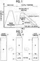
- FIG. 1 is a temperature chart showing a method of producing a steel plate member according to the first embodiment.
- the horizontal axis represents time (s), and the vertical axis represents a temperature (°C).
- the method of producing a steel plate member according to the first embodiment includes a quenching step and a partial tempering step.
- the partial tempering step is performed after the quenching step is performed.
- the entire steel plate member is heated at a temperature that is higher than a transformation temperature A3 at which austenitization is completed.
- the transformation temperature A3 at which austenitization is completed is, for example, 910°C.
- the microstructure of the entire steel plate member changes from ferrite and pearlite to an austenite single phase.
- the steel plate member is cooled at a cooling rate that is higher than an upper critical cooling rate.
- the upper critical cooling rate is a minimum cooling rate at which the microstructure transforms only to martensite.
- the steel plate member is preferably press-molded. Since hot press forming is performed, it is possible to obtain a high strength steel plate member by quenching after press molding while spring back occurring in cold press forming is restrained.
- hot pressing is generally called a hot stamp.
- a steel plate for a hot stamp for example, a steel plate made of manganese and boron steel with a thickness of about 1 mm to 4 mm is used.
- a first area 11 of the steel plate member is not reheated, and only a second area 12 of the steel plate member is reheated at a temperature that is higher than a transformation temperature A1 at which austenitization starts and is lower than a transformation temperature A3 at which austenitization is completed.
- the transformation temperature A1 at which austenitization starts is, for example, 725°C.
- a boundary area 13 between the first area 11 and the second area 12 is heated to a temperature that is lower than the transformation temperature A1 at which austenitization starts by heat conduction from the second area 12 and thermally affected.
- a general tempering temperature is a temperature that is lower than the transformation temperature A1 at which austenitization starts
- a heating temperature in the partial tempering step according to the first embodiment is a temperature higher than the general tempering temperature.
- the steel plate member is cooled at a cooling rate lower than a lower critical cooling rate so that the second area 12 does not undergo martensitic transformation.
- a dashed arrow in FIG. 1 after the change from austenite to ferrite and pearlite is completed, rapid cooling may be performed.
- the lower critical cooling rate is a minimum cooling rate at which martensite appears for the first time.
- FIG. 1 schematically shows a transformation temperature Ms at which martensitic transformation starts and a transformation temperature Mf at which martensitic transformation ends in a continuous cooling transformation (CCT) diagram and a nose point of a time-temperature-transformation diagram of ferrite/pearlite. That is, FIG. 1 schematically shows a case in which the second area 12 reheated at a temperature between the transformation temperature A1 at which austenitization starts and the transformation temperature A3 at which austenitization is completed is cooled at a cooling rate that is lower than the lower critical cooling rate.
- CCT continuous cooling transformation
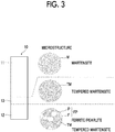
- FIG. 2 is a schematic plan view showing a change in a microstructure of the steel plate member in the partial tempering step.
- a microstructure of a steel plate member 10 before the partial tempering step shown on the left side in FIG. 2 that is, after the quenching step, will be described.
- the entire microstructure of the steel plate member 10 before the partial tempering step is composed of martensite M.
- the martensite M changes to tempered martensite TM and a part of the tempered martensite TM additionally changes to austenite A. That is, the microstructure of the second area 12 is a mixed structure of the tempered martensite TM and the austenite A.
- the tempered martensite TM in this specification generally refers to martensite M that is softened by reheating and includes troostite and sorbate.
- the first area 11 of the steel plate member 10 is an area that is not reheated and is not thermally affected.
- the microstructure of the first area 11 does not change from the martensite M.
- the boundary area 13 between the first area 11 and the second area 12 is heated at a temperature that is lower than the transformation temperature A1 at which austenitization starts by heat conduction from the second area 12 and is thermally affected.
- the microstructure of the boundary area 13 changes from the martensite M to the tempered martensite TM.
- the boundary area 13 when a distance from the second area 12 is shorter, it is heated at a temperature closer to the transformation temperature A1 at which austenitization starts.
- the microstructure on the side of the second area 12 which is most of the boundary area 13 is composed of only the tempered martensite TM.
- the tempered martensite TM and the martensite M coexist, and toward the first area 11 composed of only the martensite M, an amount of the tempered martensite TM decreases and an amount of the martensite M increases.
- this part of the boundary area 13 in which the tempered martensite TM and the martensite M coexist is not specifically shown in FIG. 2 . In this manner, when a distance from the second area 12 is shorter, since the tempered martensite TM heated at a high temperature is included, the boundary area 13 gradually becomes soft from the side of the hard first area 11 toward the side of the soft second area 12.
- the steel plate member 10 when cooling is performed in the partial tempering step, the steel plate member 10 is cooled at a cooling rate lower than the lower critical cooling rate.
- the austenite A of the second area 12 appearing during heating changes to ferrite F and pearlite P (ferrite/pearlite FP).
- the microstructure of the second area 12 is a mixed structure of the tempered martensite TM and the ferrite/pearlite FP.
- the microstructure of the first area 11 does not change from the martensite M.
- the microstructure of the boundary area 13 also does not change from the tempered martensite TM.
- a temperature of the second area 12 before cooling is set to be lower than the transformation temperature A3 at which austenitization is completed during reheating so that an area composed of only the ferrite/pearlite FP does not occur in the second area 12.
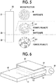
- FIG. 3 is a schematic plan view of the steel plate member according to the first embodiment.
- the steel plate member according to the first embodiment is a steel plate member produced using the method of producing a steel plate member according to the first embodiment shown in FIG. 1 .
- the steel plate member 10 includes the first area 11, the second area 12, and the boundary area 13.
- FIG. 3 schematically shows microstructures of the first area 11, the second area 12, and the boundary area 13.
- the microstructure of the steel plate member 10 shown in FIG. 3 matches the microstructure of the steel plate member 10 after the partial tempering step shown on the right side in FIG. 2 .
- the first area 11 is a hard area composed of hard martensite M.
- the second area 12 is a soft area composed of soft ferrite F and pearlite P (ferrite/pearlite FP) and soft tempered martensite TM.
- the boundary area 13 is formed between the first area 11 and the second area 12.
- the side on the second area 12 which is most of the boundary area 13 has a microstructure composed of only the tempered martensite TM.
- an amount of the tempered martensite TM decreases and an amount of the martensite M increases.
- FIG. 4 is a temperature chart showing a method of producing a steel plate member according to the comparative example of the first embodiment.
- FIG. 5 is a schematic plan view of the steel plate member according to the comparative example of the first embodiment.
- the method of producing a steel plate member according to the comparative example will be described with reference to FIG. 4 .
- the horizontal axis represents time (s) and the vertical axis represents a temperature (°C).
- the method of producing a steel plate member according to the comparative example includes only a partial quenching step.
- a partial area of the steel plate member is heated to a temperature that is higher than the transformation completion temperature A3 at which austenitization is completed.
- a second area 22 of the steel plate member is not heated and only a first area 21 of the steel plate member is heated to a temperature higher than the transformation completion temperature A3 at which austenitization is completed.
- the microstructure of the first area 21 changes from ferrite and pearlite to an austenite single phase.
- the second area 22 includes an area heated to a temperature lower than the transformation temperature A1 at which austenitization starts. The microstructure of the second area 22 does not change from ferrite and pearlite.
- a boundary area 23 between the first area 21 and the second area 22 is heated to a temperature that is higher than the transformation temperature A1 at which austenitization starts and is lower than the transformation temperature A3 at which austenitization is completed by heat conduction from the second area 22.
- the microstructure of the boundary area 23 a part of ferrite and pearlite changes to austenite. That is, the microstructure of the boundary area 23 is a mixed structure of ferrite/pearlite and austenite.
- the steel plate member is cooled at a cooling rate higher than the upper critical cooling rate. Therefore, the entire austenite undergoes martensitic transformation, and the microstructure of the first area 21 changes to hard martensite.
- the microstructure of the boundary area 23 is a mixed structure of soft ferrite and pearlite and hard martensite.
- the microstructure of the second area 22 does not change from ferrite and pearlite.
- the steel plate member according to the comparative example is a steel plate member produced using the method of producing a steel plate member according to the comparative example shown in FIG. 4 .
- a steel plate member 20 according to the comparative example includes the first area 21, the second area 22, and the boundary area 23.
- FIG. 5 schematically shows microstructures of the first area 21, the second area 22, and the boundary area 23.
- the first area 21 is a hard area composed of hard martensite.
- the second area 22 is a soft area composed of soft ferrite F and pearlite P (ferrite/pearlite FP).
- the boundary area 23 is formed between the first area 21 and the second area 22 and has a mixed structure of soft ferrite/pearlite FP and hard martensite M.
- the boundary area 23 has an unstable microstructure in which hard martensite M and soft ferrite/pearlite FP coexist.
- cracks are likely to occur in a boundary area between the hard area and the soft area.
- the boundary area 23 has an unstable microstructure in which hard martensite M and soft ferrite/pearlite FP coexist.
- the boundary area 13 has a microstructure composed of only tempered martensite TM.
- the boundary area 13 of the steel plate member 10 according to the first embodiment when a distance from the second area 12 heated in the partial tempering step is shorter, since it is heated at a higher temperature, the area becomes soft. That is, the boundary area 13 of the steel plate member 10 according to the first embodiment gradually becomes soft from the side of the hard first area 11 toward the side of the soft second area 12. Therefore, it is possible to more effectively restrain the occurrence of cracks in the boundary area 13 between the hard first area 11 and the soft second area 12.
- the second area 12 which is a soft area has a microstructure in which ferrite/pearlite FP and tempered martensite TM coexist.
- the ferrite/pearlite FP and the tempered martensite TM are also soft, cracks are unlikely to occur in the second area 12.
- FIG. 6 is a schematic perspective view of an induction heating device used in the method of producing a steel plate member according to the second embodiment.
- a method of heating the steel plate member 10 in the partial tempering step is not particularly limited.
- an induction heating device 30 shown in FIG. 6 is used to heat the steel plate member 10 in the partial tempering step. Since the other parts are the same as those in the first embodiment, detailed descriptions thereof will be omitted.
- the induction heating device 30 is a high frequency induction heating device including a coil 31 and a high frequency power supply 32.
- the coil 31 is a plate-like member having a U-shaped horizontal cross section.
- the high frequency power supply 32 is connected to both open ends of the coil 31.
- Only the second area 12 of the steel plate member 10 is inserted into the coil 31 and is induction-heated to a temperature that is higher than the transformation temperature A1 at which austenitization starts and is lower than the transformation temperature A3 at which austenitization is completed. Since the first area 11 of the steel plate member 10 is exposed out of the coil 31, it is not induction-heated and is not thermally affected by heat conduction from the second area 12. On the other hand, the boundary area 13 between the first area 11 and the second area 12 is heated to a temperature lower than the transformation temperature A1 at which austenitization starts by heat conduction from the second area 12 and is thermally affected.
- the heating efficiency sharply decreases at a Curie point at which the steel plate member 10 loses its magnetism, it is difficult to increase the heating temperature near the Curie point.
- austenite is nonmagnetic, and martensite, ferrite and pearlite are ferromagnetic, the Curie point is between the transformation temperature A1 at which austenitization starts and the transformation temperature A3 at which austenitization is completed.
- FIG. 7 is a temperature chart of induction heating of steel plates with different thicknesses.
- the horizontal axis represents time and the vertical axis represents a temperature.
- Steel plates PL1 and PL2 are both steel plates for a hot stamp made of manganese and boron steel (22MnB5 steel).
- the steel plate PL2 is about 1 mm thicker than the steel plate PL1.
- high frequency induction heating it is possible to quickly heat both of the steel plates PL1 and PL2.
- FIG. 8 is a temperature chart showing conditions of partial tempering according to the example of the second embodiment.
- the horizontal axis represents time and the vertical axis represents a temperature.
- FIG. 8 shows a temperature profile in four areas: the first area 11, the second area 12, the boundary area 13 (first area side), and the boundary area 13 (second area side). As shown in FIG.
- a hard area composed of the martensite M is formed in the first area 11 shown in FIG. 8 .
- a soft area composed of ferrite/pearlite FP and tempered martensite TM is formed in the second area 12 shown in FIG. 8 .
- the boundary area 13 on the side of the first area and the boundary area 13 on the side of the second area shown in FIG. 8 both have a microstructure composed of only the tempered martensite TM.
- the hardness of the boundary area 13 on the side of the second area heated to a higher temperature is lower than the hardness of the boundary area 13 on the side of the first area.
- FIG. 9 and FIG. 10 show the hardness distribution of the steel plate member produced using the method of producing a steel plate member according to the example of the second embodiment and microstructure pictures.
- FIG. 9 is a graph showing the hardness distribution of the steel plate member produced using the method of producing a steel plate member according to the second embodiment.
- FIG. 10 shows microstructure pictures of the steel plate member produced using the method of producing a steel plate member according to the second embodiment.
- the boundary area 13 is formed between the hard first area 11 having a high Vickers hardness (HV) and the soft second area 12 having a low Vickers hardness (HV). As shown in FIG. 9 , when high frequency induction heating is used, the boundary area 13 that is thermally affected by heat conduction from the second area 12 is narrowed to about 50 mm. In addition, it is found that the boundary area 13 is gradually softened from the side of the hard first area 11 toward the side of the soft second area 12.
- the microstructure of the first area 11 is a structure composed of only martensite.
- the microstructure of the second area 12 is a mixed structure of ferrite/pearlite and tempered martensite.
- the boundary area 13A has a microstructure composed of only tempered martensite. That is, the same microstructure as the microstructure shown in FIG. 3 is actually obtained.
- FIG. 11 is a comparison graph showing the hardness and limit bending angle of the boundary area 13 of the steel plate member according to the example and the boundary area 23 of the steel plate member according to the comparative example.
- a bending test for obtaining a limit bending angle (deg) is performed according to VDA238-100, standards of German Association of the Automotive Industry.
- the Vickers hardness (HV) of the boundary area 13 in the example is the same as the Vickers hardness (HV) of the boundary area 23 in the comparative example.
- the limit bending angle (deg) of the boundary area 13 in the example is twice or more as large as the limit bending angle (deg) of the boundary area 23 in the comparative example and the bendability is significantly improved.
- the boundary area 23 in the comparative example has an unstable microstructure in which the hard martensite M and the soft ferrite/pearlite FP coexisted, the bendability deteriorated.
- the boundary area 13 in the example has a structure composed of only tempered martensite, the bendability is excellent.
Landscapes
- Chemical & Material Sciences (AREA)
- Engineering & Computer Science (AREA)
- Crystallography & Structural Chemistry (AREA)
- Mechanical Engineering (AREA)
- Materials Engineering (AREA)
- Metallurgy (AREA)
- Organic Chemistry (AREA)
- Physics & Mathematics (AREA)
- Thermal Sciences (AREA)
- Heat Treatment Of Articles (AREA)
Abstract
Description
- The present invention relates to a steel plate member and a method of producing the steel plate member, and particularly, to a steel plate member including a hard area containing martensite and a soft area containing ferrite and pearlite and a method of producing the steel plate member.
- In recent years, for example, as a structural member for a vehicle, in order to improve impact resistance, a steel plate member including a hard area that is resistant to shock and a soft area that absorbs shock has been developed. In Japanese Unexamined Patent Application Publication No.
2012-144773 JP2012-144773 A - In the method of producing a steel plate member including a hard area and a soft area disclosed in
JP2012-144773 A - Here, a boundary area between the hard area and the soft area is heated at a temperature between the austenite transformation start temperature A1 and the austenite transformation completion temperature A3, and some of ferrite and pearlite change to austenite. Thus, after quenching, the boundary area has an unstable microstructure in which hard martensite and soft ferrite and pearlite coexist. As a result, cracks are likely to occur in the boundary area between the hard area and the soft area, and local ductility and bendability deteriorate.
- The present invention provides a steel plate member in which the occurrence of cracks in a boundary area between a hard area and a soft area is restrained and a method of producing the steel plate member.
- An aspect of the invention relates to a method of producing a steel plate member including: quenching a steel plate by heating the steel plate to a temperature which is higher than a first transformation temperature at which austenitization is completed and then cooling the steel plate at a cooling rate higher than an upper critical cooling rate; reheating a second area of the steel plate, without reheating a first area of the steel plate, to a temperature which is higher than a second transformation temperature, at which austenitization starts, and is lower than the first transformation temperature; and cooling the reheated steel plate at a cooling rate lower than a lower critical cooling rate to obtain the steel plate member in which a hard area composed of martensite is formed in the first area, a soft area containing tempered martensite in addition to ferrite and pearlite is formed in the second area, and an area composed of only tempered martensite is formed in a third area between the first area and the second area.
- In the method of producing a steel plate member of the above aspect, in the tempering step, the first area of the steel plate is not reheated, and the second area of the steel plate is reheated to a temperature that is higher than a transformation temperature at which austenitization starts and is lower than a transformation temperature at which austenitization is completed. Then, the steel plate is cooled at a cooling rate lower than a lower critical cooling rate. Therefore, a hard area composed of martensite is formed in the first area, a soft area containing tempered martensite in addition to ferrite and pearlite is formed in the second area, and an area composed of only tempered martensite is formed in the third area between the first area and the second area. That is, according to the method of producing a steel plate member of the above aspect, since an unstable microstructure in which the hard martensite and the soft ferrite and pearlite coexist is not formed in the third area, it is possible to restrain the occurrence of cracks in the third area.
- In the above aspect, the second area of the steel plate may be reheated by induction heating.
- According to the method of producing a steel plate member of the above aspect, it is possible to quickly heat the second area of the steel plate and it is possible to accurately maintain the temperature that is higher than the transformation temperature at which austenitization starts and is lower than the transformation temperature at which austenitization is completed.
- In the above aspect, after the steel plate is heated, a press processing may be performed on the steel plate before the steel plate is cooled during quenching.
- According to the method of producing a steel plate member of the above aspect, it is possible to obtain a high strength steel plate member by cooling after press molding while spring back occurring in cold press forming is restrained.
- In the above aspect, the third area may be heated to a temperature which is lower than the second transformation temperature by heat conduction from the second area being reheated; and a structure of the third area may change from martensite to tempered martensite.
- Another aspect of the invention relates to a steel plate member including: a hard area composed of martensite; a soft area containing ferrite and pearlite; and a third area which is formed between the hard area and the soft area, wherein: the soft area further contains tempered martensite; and the third area includes an area composed of only tempered martensite.
- In the steel plate member of the above aspect, an area composed of only tempered martensite is formed in the third area, and an unstable microstructure in which the hard martensite and the soft ferrite and pearlite coexist is not formed in the third area. Therefore, according to the steel plate member of the above aspect, it is possible to restrain the occurrence of cracks in the third area.
- According to the present invention, it is possible to provide a steel plate member in which the occurrence of cracks in a boundary area between a hard area and a soft area is restrained and a method of producing the steel plate member.
- Features, advantages, and technical and industrial significance of exemplary embodiments of the invention will be described below with reference to the accompanying drawings, in which like numerals denote like elements, and wherein:
-
FIG. 1 is a temperature chart showing a method of producing a steel plate member according to a first embodiment; -
FIG. 2 is a schematic plan view showing a change in a microstructure of a steel plate member in a partial tempering step; -
FIG. 3 is a schematic plan view of a steel plate member according to the first embodiment; -
FIG. 4 is a temperature chart showing a method of producing a steel plate member according to a comparative example of the first embodiment; -
FIG. 5 is a schematic plan view of a steel plate member according to the comparative example of the first embodiment; -
FIG. 6 is a schematic perspective view of an induction heating device used in a method of producing a steel plate member according to a second embodiment; -
FIG. 7 is a temperature chart of induction heating of steel plates with different thicknesses; -
FIG. 8 is a temperature chart showing conditions of partial tempering according to an example of the second embodiment; -
FIG. 9 is a graph showing a hardness distribution of the steel plate member produced using the method of producing a steel plate member according to the example of the second embodiment; -
FIG. 10 is a microstructure picture of the steel plate member produced using the method of producing a steel plate member according to the second embodiment; and -
FIG. 11 is a comparison graph showing the hardnesses and limit bending angles of aboundary area 13 of the steel plate member according to the example and aboundary area 23 of the steel plate member according to the comparative example. - Specific embodiments in which the present invention is applied will be described below in detail with reference to the drawings. However, the present invention is not limited to the following embodiments. In addition, in order to clarify the description, the following description and drawings are appropriately simplified.
- First, a method of producing a steel plate member according to a first embodiment will be described with reference to
FIG. 1 . The method of producing a steel plate member according to the first embodiment is appropriate, for example, as a method of producing a steel plate member for a vehicle including a hard area that is resistant to shock and a soft area that absorbs shock. -
FIG. 1 is a temperature chart showing a method of producing a steel plate member according to the first embodiment. InFIG. 1 , the horizontal axis represents time (s), and the vertical axis represents a temperature (°C). As shown inFIG. 1 , the method of producing a steel plate member according to the first embodiment includes a quenching step and a partial tempering step. In the method of producing a steel plate member according to the first embodiment, the partial tempering step is performed after the quenching step is performed. - First, in the quenching step, the entire steel plate member is heated at a temperature that is higher than a transformation temperature A3 at which austenitization is completed. The transformation temperature A3 at which austenitization is completed is, for example, 910°C. In this case, the microstructure of the entire steel plate member changes from ferrite and pearlite to an austenite single phase. Then, the steel plate member is cooled at a cooling rate that is higher than an upper critical cooling rate. Thereby, the steel plate member undergoes martensitic transformation, and the microstructure of the entire steel plate member changes to hard martensite. The upper critical cooling rate is a minimum cooling rate at which the microstructure transforms only to martensite.
- Here, after the steel plate member is heated, before the steel plate member is cooled, the steel plate member is preferably press-molded. Since hot press forming is performed, it is possible to obtain a high strength steel plate member by quenching after press molding while spring back occurring in cold press forming is restrained. Here, such hot pressing is generally called a hot stamp. Although not particularly limited, as a steel plate for a hot stamp, for example, a steel plate made of manganese and boron steel with a thickness of about 1 mm to 4 mm is used.
- Next, in the partial tempering step, only a partial area of the steel plate member is reheated and softened. Specifically, as shown in
FIG. 1 , afirst area 11 of the steel plate member is not reheated, and only asecond area 12 of the steel plate member is reheated at a temperature that is higher than a transformation temperature A1 at which austenitization starts and is lower than a transformation temperature A3 at which austenitization is completed. The transformation temperature A1 at which austenitization starts is, for example, 725°C. In this case, aboundary area 13 between thefirst area 11 and thesecond area 12 is heated to a temperature that is lower than the transformation temperature A1 at which austenitization starts by heat conduction from thesecond area 12 and thermally affected. Here, a general tempering temperature is a temperature that is lower than the transformation temperature A1 at which austenitization starts, and a heating temperature in the partial tempering step according to the first embodiment is a temperature higher than the general tempering temperature. - Then, the steel plate member is cooled at a cooling rate lower than a lower critical cooling rate so that the
second area 12 does not undergo martensitic transformation. In this case, as indicated by a dashed arrow inFIG. 1 , after the change from austenite to ferrite and pearlite is completed, rapid cooling may be performed. When rapid cooling is performed, since a time for producing the steel plate member is shortened, it is possible to improve the production efficiency. The lower critical cooling rate is a minimum cooling rate at which martensite appears for the first time. - Here,
FIG. 1 schematically shows a transformation temperature Ms at which martensitic transformation starts and a transformation temperature Mf at which martensitic transformation ends in a continuous cooling transformation (CCT) diagram and a nose point of a time-temperature-transformation diagram of ferrite/pearlite. That is,FIG. 1 schematically shows a case in which thesecond area 12 reheated at a temperature between the transformation temperature A1 at which austenitization starts and the transformation temperature A3 at which austenitization is completed is cooled at a cooling rate that is lower than the lower critical cooling rate. - Here,
FIG. 2 is a schematic plan view showing a change in a microstructure of the steel plate member in the partial tempering step. First, a microstructure of asteel plate member 10 before the partial tempering step shown on the left side inFIG. 2 , that is, after the quenching step, will be described. As shown on the left side inFIG. 2 , the entire microstructure of thesteel plate member 10 before the partial tempering step is composed of martensite M. - Next, the microstructure of the
steel plate member 10 during heating in the partial tempering step shown in the center inFIG. 2 will be described. As shown in the temperature chart inFIG. 1 , during heating in the partial tempering step, only thesecond area 12 of thesteel plate member 10 is reheated at a temperature that is higher than the transformation temperature A1 at which austenitization starts and is lower than the transformation temperature A3 at which austenitization is completed. - Thus, as shown in the center in
FIG. 2 , during heating in the partial tempering step, in thesecond area 12, the martensite M changes to tempered martensite TM and a part of the tempered martensite TM additionally changes to austenite A. That is, the microstructure of thesecond area 12 is a mixed structure of the tempered martensite TM and the austenite A. Here, in the vicinity of theboundary area 13 in thesecond area 12, since a heating temperature approaches the transformation temperature A1 at which austenitization starts, an amount of the austenite A decreases, and an amount of the tempered martensite TM increases. Here, the tempered martensite TM in this specification generally refers to martensite M that is softened by reheating and includes troostite and sorbate. - On the other hand, the
first area 11 of thesteel plate member 10 is an area that is not reheated and is not thermally affected. Thus, the microstructure of thefirst area 11 does not change from the martensite M. Here, theboundary area 13 between thefirst area 11 and thesecond area 12 is heated at a temperature that is lower than the transformation temperature A1 at which austenitization starts by heat conduction from thesecond area 12 and is thermally affected. Thus, the microstructure of theboundary area 13 changes from the martensite M to the tempered martensite TM. - More specifically, in the
boundary area 13, when a distance from thesecond area 12 is shorter, it is heated at a temperature closer to the transformation temperature A1 at which austenitization starts. Thus, the microstructure on the side of thesecond area 12 which is most of theboundary area 13 is composed of only the tempered martensite TM. Here, in the vicinity of thefirst area 11 in theboundary area 13, the tempered martensite TM and the martensite M coexist, and toward thefirst area 11 composed of only the martensite M, an amount of the tempered martensite TM decreases and an amount of the martensite M increases. Note that, this part of theboundary area 13 in which the tempered martensite TM and the martensite M coexist is not specifically shown inFIG. 2 . In this manner, when a distance from thesecond area 12 is shorter, since the tempered martensite TM heated at a high temperature is included, theboundary area 13 gradually becomes soft from the side of the hardfirst area 11 toward the side of the softsecond area 12. - Next, a microstructure of the
steel plate member 10 after the partial tempering step shown on the right side inFIG. 2 will be described. As shown inFIG. 1 , when cooling is performed in the partial tempering step, thesteel plate member 10 is cooled at a cooling rate lower than the lower critical cooling rate. Thus, as shown on the right side inFIG. 2 , the austenite A of thesecond area 12 appearing during heating changes to ferrite F and pearlite P (ferrite/pearlite FP). As a result, the microstructure of thesecond area 12 is a mixed structure of the tempered martensite TM and the ferrite/pearlite FP. The microstructure of thefirst area 11 does not change from the martensite M. The microstructure of theboundary area 13 also does not change from the tempered martensite TM. - Here, when the
second area 12 is reheated to a temperature that is higher than the transformation temperature A3 at which austenitization is completed, thesecond area 12 after cooling becomes a microstructure composed of only ferrite/pearlite FP and sufficient strength is not obtained. Thus, a temperature of thesecond area 12 before cooling is set to be lower than the transformation temperature A3 at which austenitization is completed during reheating so that an area composed of only the ferrite/pearlite FP does not occur in thesecond area 12. - Next, a steel plate member according to the first embodiment will be described with reference to
FIG. 3. FIG. 3 is a schematic plan view of the steel plate member according to the first embodiment. The steel plate member according to the first embodiment is a steel plate member produced using the method of producing a steel plate member according to the first embodiment shown inFIG. 1 . - As shown in
FIG. 3 , thesteel plate member 10 according to the first embodiment includes thefirst area 11, thesecond area 12, and theboundary area 13.FIG. 3 schematically shows microstructures of thefirst area 11, thesecond area 12, and theboundary area 13. Here, the microstructure of thesteel plate member 10 shown inFIG. 3 matches the microstructure of thesteel plate member 10 after the partial tempering step shown on the right side inFIG. 2 . - As shown in
FIG. 3 , thefirst area 11 is a hard area composed of hard martensite M. Thesecond area 12 is a soft area composed of soft ferrite F and pearlite P (ferrite/pearlite FP) and soft tempered martensite TM. Theboundary area 13 is formed between thefirst area 11 and thesecond area 12. The side on thesecond area 12 which is most of theboundary area 13 has a microstructure composed of only the tempered martensite TM. Here, in the vicinity of thefirst area 11 in theboundary area 13, the tempered martensite TM and the martensite M coexist, and toward thefirst area 11, an amount of the tempered martensite TM decreases and an amount of the martensite M increases. - Here, a steel plate member according to a comparative example of the first embodiment and a method of producing the same will be described with reference to
FIG. 4 andFIG. 5 .FIG. 4 is a temperature chart showing a method of producing a steel plate member according to the comparative example of the first embodiment.FIG. 5 is a schematic plan view of the steel plate member according to the comparative example of the first embodiment. First, the method of producing a steel plate member according to the comparative example will be described with reference toFIG. 4 . InFIG. 4 , the horizontal axis represents time (s) and the vertical axis represents a temperature (°C). As shown inFIG. 4 , the method of producing a steel plate member according to the comparative example includes only a partial quenching step. - In the partial quenching step, only a partial area of the steel plate member is heated to a temperature that is higher than the transformation completion temperature A3 at which austenitization is completed. Specifically, as shown in
FIG. 4 , asecond area 22 of the steel plate member is not heated and only afirst area 21 of the steel plate member is heated to a temperature higher than the transformation completion temperature A3 at which austenitization is completed. Thus, the microstructure of thefirst area 21 changes from ferrite and pearlite to an austenite single phase. Here, thesecond area 22 includes an area heated to a temperature lower than the transformation temperature A1 at which austenitization starts. The microstructure of thesecond area 22 does not change from ferrite and pearlite. - Then, a
boundary area 23 between thefirst area 21 and thesecond area 22 is heated to a temperature that is higher than the transformation temperature A1 at which austenitization starts and is lower than the transformation temperature A3 at which austenitization is completed by heat conduction from thesecond area 22. Thus, in the microstructure of theboundary area 23, a part of ferrite and pearlite changes to austenite. That is, the microstructure of theboundary area 23 is a mixed structure of ferrite/pearlite and austenite. - Then, the steel plate member is cooled at a cooling rate higher than the upper critical cooling rate. Therefore, the entire austenite undergoes martensitic transformation, and the microstructure of the
first area 21 changes to hard martensite. In addition, the microstructure of theboundary area 23 is a mixed structure of soft ferrite and pearlite and hard martensite. Here, the microstructure of thesecond area 22 does not change from ferrite and pearlite. - Next, the steel plate member according to the comparative example of the first embodiment will be described with reference to
FIG. 5 . The steel plate member according to the comparative example is a steel plate member produced using the method of producing a steel plate member according to the comparative example shown inFIG. 4 . As shown inFIG. 5 , asteel plate member 20 according to the comparative example includes thefirst area 21, thesecond area 22, and theboundary area 23.FIG. 5 schematically shows microstructures of thefirst area 21, thesecond area 22, and theboundary area 23. - As shown in
FIG. 5 , thefirst area 21 is a hard area composed of hard martensite. Thesecond area 22 is a soft area composed of soft ferrite F and pearlite P (ferrite/pearlite FP). Theboundary area 23 is formed between thefirst area 21 and thesecond area 22 and has a mixed structure of soft ferrite/pearlite FP and hard martensite M. - In this manner, in the
steel plate member 20 according to the comparative example, theboundary area 23 has an unstable microstructure in which hard martensite M and soft ferrite/pearlite FP coexist. Thus, cracks are likely to occur in a boundary area between the hard area and the soft area. - Next, effects according to a steel plate member according to the first embodiment and a method of producing the same will be described. As described above, in the
steel plate member 20 according to the comparative example shown inFIG. 5 , theboundary area 23 has an unstable microstructure in which hard martensite M and soft ferrite/pearlite FP coexist. On the other hand, in thesteel plate member 10 according to the first embodiment, as shown inFIG. 3 , theboundary area 13 has a microstructure composed of only tempered martensite TM. Thus, it is possible to restrain the occurrence of cracks in theboundary area 13 between the hardfirst area 11 and the softsecond area 12. Here, in the vicinity of thefirst area 11 in theboundary area 13, while the tempered martensite TM and the martensite M coexist, since a hardness difference between them when they are adjacent to each other is small, the occurrence of cracks can be restrained. - In addition, in the
boundary area 13 of thesteel plate member 10 according to the first embodiment, when a distance from thesecond area 12 heated in the partial tempering step is shorter, since it is heated at a higher temperature, the area becomes soft. That is, theboundary area 13 of thesteel plate member 10 according to the first embodiment gradually becomes soft from the side of the hardfirst area 11 toward the side of the softsecond area 12. Therefore, it is possible to more effectively restrain the occurrence of cracks in theboundary area 13 between the hardfirst area 11 and the softsecond area 12. - Here, in the
steel plate member 10 according to the first embodiment, thesecond area 12 which is a soft area has a microstructure in which ferrite/pearlite FP and tempered martensite TM coexist. However, since the ferrite/pearlite FP and the tempered martensite TM are also soft, cracks are unlikely to occur in thesecond area 12. - Next, a method of producing a steel plate member according to a second embodiment will be described with reference to
FIG. 6. FIG. 6 is a schematic perspective view of an induction heating device used in the method of producing a steel plate member according to the second embodiment. In the method of producing a steel plate member according to the first embodiment, a method of heating thesteel plate member 10 in the partial tempering step is not particularly limited. On the other hand, in the method of producing a steel plate member according to the second embodiment, aninduction heating device 30 shown inFIG. 6 is used to heat thesteel plate member 10 in the partial tempering step. Since the other parts are the same as those in the first embodiment, detailed descriptions thereof will be omitted. - As shown in
FIG. 6 , theinduction heating device 30 is a high frequency induction heating device including acoil 31 and a highfrequency power supply 32. As shown inFIG. 6 , thecoil 31 is a plate-like member having a U-shaped horizontal cross section. The highfrequency power supply 32 is connected to both open ends of thecoil 31. Only thesecond area 12 of thesteel plate member 10 is inserted into thecoil 31 and is induction-heated to a temperature that is higher than the transformation temperature A1 at which austenitization starts and is lower than the transformation temperature A3 at which austenitization is completed. Since thefirst area 11 of thesteel plate member 10 is exposed out of thecoil 31, it is not induction-heated and is not thermally affected by heat conduction from thesecond area 12. On the other hand, theboundary area 13 between thefirst area 11 and thesecond area 12 is heated to a temperature lower than the transformation temperature A1 at which austenitization starts by heat conduction from thesecond area 12 and is thermally affected. - Here, in high frequency induction heating, since the heating efficiency sharply decreases at a Curie point at which the
steel plate member 10 loses its magnetism, it is difficult to increase the heating temperature near the Curie point. Since austenite is nonmagnetic, and martensite, ferrite and pearlite are ferromagnetic, the Curie point is between the transformation temperature A1 at which austenitization starts and the transformation temperature A3 at which austenitization is completed. - Therefore, when high frequency induction heating is used, it is possible to quickly heat only the
second area 12 of thesteel plate member 10 and it is possible to easily and accurately maintain the temperature that is higher than the transformation temperature A1 at which austenitization starts and is lower than the transformation temperature A3 at which austenitization is completed. Since it is possible to quickly heat only thesecond area 12 of thesteel plate member 10, it is possible to narrow theboundary area 13 that is thermally affected by heat conduction from thesecond area 12. -
FIG. 7 is a temperature chart of induction heating of steel plates with different thicknesses. The horizontal axis represents time and the vertical axis represents a temperature. Steel plates PL1 and PL2 are both steel plates for a hot stamp made of manganese and boron steel (22MnB5 steel). Here, the steel plate PL2 is about 1 mm thicker than the steel plate PL1. Thus, compared to the steel plate PL1, it takes longer to heat the steel plate PL2. However, when high frequency induction heating is used, it is possible to quickly heat both of the steel plates PL1 and PL2. In addition, when high frequency induction heating is used, it is possible to easily and accurately maintain both of the steel plates PL1 and PL2 with different thicknesses at a temperature that is higher than the transformation temperature A1 at which austenitization starts and is lower than the transformation temperature A3 at which austenitization is completed. - An example of the second embodiment in which a steel plate member is induction-heated in partial tempering will be described below. As a steel plate member, a quenched component of a steel plate for a hot stamp made of manganese and boron steel (22MnB5 steel) and with a thickness of 2.0 mm, a width of 100 mm, and a length of 300 mm is used.
FIG. 8 is a temperature chart showing conditions of partial tempering according to the example of the second embodiment. The horizontal axis represents time and the vertical axis represents a temperature.FIG. 8 shows a temperature profile in four areas: thefirst area 11, thesecond area 12, the boundary area 13 (first area side), and the boundary area 13 (second area side). As shown inFIG. 8 , only thesecond area 12 of the steel plate member is heated to a temperature that is higher than the transformation temperature A1 at which austenitization started and is lower than the transformation temperature A3 at which austenitization is completed and the steel plate member is then cooled at a cooling rate lower than the upper critical cooling rate so that thesecond area 12 does not undergo martensitic transformation. - As will be described in detail below, as a result of the partial tempering performed according to the example, a hard area composed of the martensite M is formed in the
first area 11 shown inFIG. 8 . In thesecond area 12 shown inFIG. 8 , a soft area composed of ferrite/pearlite FP and tempered martensite TM is formed. Theboundary area 13 on the side of the first area and theboundary area 13 on the side of the second area shown inFIG. 8 both have a microstructure composed of only the tempered martensite TM. On the other hand, the hardness of theboundary area 13 on the side of the second area heated to a higher temperature is lower than the hardness of theboundary area 13 on the side of the first area. -
FIG. 9 and FIG. 10 show the hardness distribution of the steel plate member produced using the method of producing a steel plate member according to the example of the second embodiment and microstructure pictures.FIG. 9 is a graph showing the hardness distribution of the steel plate member produced using the method of producing a steel plate member according to the second embodiment.FIG. 10 shows microstructure pictures of the steel plate member produced using the method of producing a steel plate member according to the second embodiment. - As shown in
FIG. 9 , theboundary area 13 is formed between the hardfirst area 11 having a high Vickers hardness (HV) and the softsecond area 12 having a low Vickers hardness (HV). As shown inFIG. 9 , when high frequency induction heating is used, theboundary area 13 that is thermally affected by heat conduction from thesecond area 12 is narrowed to about 50 mm. In addition, it is found that theboundary area 13 is gradually softened from the side of the hardfirst area 11 toward the side of the softsecond area 12. - In addition, as shown in
FIG. 10 , the microstructure of thefirst area 11 is a structure composed of only martensite. The microstructure of thesecond area 12 is a mixed structure of ferrite/pearlite and tempered martensite. The boundary area 13A has a microstructure composed of only tempered martensite. That is, the same microstructure as the microstructure shown inFIG. 3 is actually obtained. -
FIG. 11 is a comparison graph showing the hardness and limit bending angle of theboundary area 13 of the steel plate member according to the example and theboundary area 23 of the steel plate member according to the comparative example. A bending test for obtaining a limit bending angle (deg) is performed according to VDA238-100, standards of German Association of the Automotive Industry. As shown inFIG. 11 , the Vickers hardness (HV) of theboundary area 13 in the example is the same as the Vickers hardness (HV) of theboundary area 23 in the comparative example. - On the other hand, as shown in
FIG. 11 , the limit bending angle (deg) of theboundary area 13 in the example is twice or more as large as the limit bending angle (deg) of theboundary area 23 in the comparative example and the bendability is significantly improved. As described with reference toFIG. 5 , since theboundary area 23 in the comparative example has an unstable microstructure in which the hard martensite M and the soft ferrite/pearlite FP coexisted, the bendability deteriorated. On the other hand, it is thought that, since theboundary area 13 in the example has a structure composed of only tempered martensite, the bendability is excellent. - Here, the present invention is not limited to the above embodiments, and can be appropriately changed without departing from the spirit and scope the invention.
Claims (5)
- A method of producing a steel plate member comprising:quenching a steel plate by heating the steel plate to a temperature which is higher than a first transformation temperature (A3) at which austenitization is completed and then cooling the steel plate at a cooling rate higher than an upper critical cooling rate;reheating a second area (12) of the steel plate, without reheating a first area (11) of the steel plate, to a temperature which is higher than a second transformation temperature (A1), at which austenitization starts, and is lower than the first transformation temperature (A3); andcooling the reheated steel plate at a cooling rate lower than a lower critical cooling rate to obtain the steel plate member in which a hard area composed of martensite (M) is formed in the first area (11), a soft area containing tempered martensite (TM) in addition to ferrite (F) and pearlite (P) is formed in the second area (12), and an area composed of only tempered martensite (TM) is formed in a third area (13) between the first area (11) and the second area (12).
- The method of producing the steel plate member according to claim 1, wherein the second area (12) of the steel plate is reheated by induction heating.
- The method of producing the steel plate member according to claim 1 or 2, wherein, after the steel plate is heated, a press processing is performed on the steel plate before the steel plate is cooled during quenching.
- The method of producing the steel plate member according to any one of claims 1 to 3, wherein:the third area (13) is heated to a temperature which is lower than the second transformation temperature (A1) by heat conduction from the second area (12) being reheated; anda structure of the third area (13) changes from martensite (M) to tempered martensite (TM).
- A steel plate member comprising:a hard area composed of martensite (M);a soft area containing ferrite (F) and pearlite (P); anda third area (13) which is formed between the hard area and the soft area, wherein: the soft area further contains tempered martensite (TM); andthe third area (13) includes an area composed of only tempered martensite (TM).
Applications Claiming Priority (2)
| Application Number | Priority Date | Filing Date | Title |
|---|---|---|---|
| JP2017197562 | 2017-10-11 | ||
| JP2018085085A JP7043958B2 (en) | 2017-10-11 | 2018-04-26 | Steel plate member and its manufacturing method |
Publications (2)
| Publication Number | Publication Date |
|---|---|
| EP3470537A1 true EP3470537A1 (en) | 2019-04-17 |
| EP3470537B1 EP3470537B1 (en) | 2021-08-25 |
Family
ID=63517685
Family Applications (1)
| Application Number | Title | Priority Date | Filing Date |
|---|---|---|---|
| EP18192567.8A Active EP3470537B1 (en) | 2017-10-11 | 2018-09-04 | Steel plate member and method of producing the steel plate member |
Country Status (4)
| Country | Link |
|---|---|
| US (1) | US20190106764A1 (en) |
| EP (1) | EP3470537B1 (en) |
| KR (1) | KR20190040892A (en) |
| CN (1) | CN109652622B (en) |
Families Citing this family (3)
| Publication number | Priority date | Publication date | Assignee | Title |
|---|---|---|---|---|
| JP6424195B2 (en) | 2016-11-14 | 2018-11-14 | 株式会社豊田中央研究所 | Hot press forming method |
| KR102100323B1 (en) | 2019-11-01 | 2020-04-13 | 주식회사 엔쓰리엔클라우드 | Method and server for the service of machine learning platform |
| JP7184022B2 (en) * | 2019-11-18 | 2022-12-06 | トヨタ自動車株式会社 | Method for manufacturing steel plate member |
Citations (6)
| Publication number | Priority date | Publication date | Assignee | Title |
|---|---|---|---|---|
| US20020104591A1 (en) * | 2000-08-19 | 2002-08-08 | Ludger Gehringhoff | B-column for motor vehicle |
| WO2011160209A1 (en) * | 2010-06-24 | 2011-12-29 | Magna International Inc. | Tailored properties by post hot forming processing |
| JP2012144773A (en) | 2011-01-12 | 2012-08-02 | Nippon Steel Corp | Metal plate for radiation transfer heating and method for producing the same, and metal worked product with different strength parts and method for producing the same |
| EP2905346A1 (en) * | 2014-01-23 | 2015-08-12 | Schwartz GmbH | Heat treatment device |
| WO2016046637A1 (en) * | 2014-09-22 | 2016-03-31 | Magna International Inc. | Method for producing a structural component including a thermomagnetic tempering process yielding localized soft zones |
| EP3323524A1 (en) * | 2016-11-14 | 2018-05-23 | Toyota Jidosha Kabushiki Kaisha | Hot-press molding method and hot-press molded product |
Family Cites Families (4)
| Publication number | Priority date | Publication date | Assignee | Title |
|---|---|---|---|---|
| US5972134A (en) * | 1997-10-02 | 1999-10-26 | Benteler Ag | Manufacture of a metallic molded structural part |
| DE102010010156A1 (en) * | 2010-03-04 | 2011-09-08 | Kirchhoff Automotive Deutschland Gmbh | Process for producing a molded part with at least two structural areas of different ductility |
| DE102013008853A1 (en) * | 2013-05-23 | 2014-11-27 | Linde Aktiengesellschaft | Plant and method for hot forming of blanks |
| JP5821911B2 (en) * | 2013-08-09 | 2015-11-24 | Jfeスチール株式会社 | High yield ratio high strength cold-rolled steel sheet and method for producing the same |
-
2018
- 2018-08-31 US US16/119,096 patent/US20190106764A1/en not_active Abandoned
- 2018-09-04 KR KR1020180105250A patent/KR20190040892A/en not_active Ceased
- 2018-09-04 EP EP18192567.8A patent/EP3470537B1/en active Active
- 2018-09-27 CN CN201811128915.5A patent/CN109652622B/en not_active Expired - Fee Related
Patent Citations (6)
| Publication number | Priority date | Publication date | Assignee | Title |
|---|---|---|---|---|
| US20020104591A1 (en) * | 2000-08-19 | 2002-08-08 | Ludger Gehringhoff | B-column for motor vehicle |
| WO2011160209A1 (en) * | 2010-06-24 | 2011-12-29 | Magna International Inc. | Tailored properties by post hot forming processing |
| JP2012144773A (en) | 2011-01-12 | 2012-08-02 | Nippon Steel Corp | Metal plate for radiation transfer heating and method for producing the same, and metal worked product with different strength parts and method for producing the same |
| EP2905346A1 (en) * | 2014-01-23 | 2015-08-12 | Schwartz GmbH | Heat treatment device |
| WO2016046637A1 (en) * | 2014-09-22 | 2016-03-31 | Magna International Inc. | Method for producing a structural component including a thermomagnetic tempering process yielding localized soft zones |
| EP3323524A1 (en) * | 2016-11-14 | 2018-05-23 | Toyota Jidosha Kabushiki Kaisha | Hot-press molding method and hot-press molded product |
Non-Patent Citations (1)
| Title |
|---|
| MERKLEIN M ET AL: "Herstellung von funktionsoptimierten Bauteilen im Presshärtprozess", STAHL UND EISEN, VERLAG STAHLEISEN, DUSSELDORF, DE, vol. 130, no. 6, 15 June 2010 (2010-06-15), pages 51 - 57, XP001558170, ISSN: 0340-4803 * |
Also Published As
| Publication number | Publication date |
|---|---|
| CN109652622B (en) | 2021-07-30 |
| EP3470537B1 (en) | 2021-08-25 |
| KR20190040892A (en) | 2019-04-19 |
| US20190106764A1 (en) | 2019-04-11 |
| CN109652622A (en) | 2019-04-19 |
Similar Documents
| Publication | Publication Date | Title |
|---|---|---|
| EP3502283B1 (en) | Steel plate member and method of producing the same | |
| Kolleck et al. | Investigation on induction heating for hot stamping of boron alloyed steels | |
| AU2011269680B2 (en) | Tailored properties by post hot forming processing | |
| JP6424195B2 (en) | Hot press forming method | |
| US20050257862A1 (en) | Production method of warm- or hot-formed product | |
| US20120090741A1 (en) | Method for producing a hot-formed and press-hardened metal component | |
| KR101277874B1 (en) | Hot forming parts having strength distribution and method for manufacturing the same | |
| EP3470537A1 (en) | Steel plate member and method of producing the steel plate member | |
| KR102006963B1 (en) | Method for producing a component by hot-forming a steel precursor product | |
| Taylor et al. | Effect of part/die boundary conditions on microstructural evolution during hot stamping 2000 MPa class boron steel | |
| CN108425001A (en) | Method for the steel plate member for manufacturing hot forming and press quenching | |
| JP7043958B2 (en) | Steel plate member and its manufacturing method | |
| KR101482336B1 (en) | Method for manufacturing hot forming parts having strength distribution | |
| KR20160045177A (en) | Method for warm forming of super high tensile strength steel sheet | |
| CN105247080B (en) | Method and hardening tool for hardening of components or semi-finished products | |
| US11898217B2 (en) | Method for producing steel plate member | |
| US10240224B2 (en) | Steel alloy with tailored hardenability | |
| Miyagawa et al. | Development of Strength Distributed Hot Stamp Parts | |
| CN107604142A (en) | A kind of intensity adjustable steel composite material | |
| CN106521108A (en) | Method of local heat treatment for collision parts of vehicle using high frequency signal | |
| Kim et al. | Influence of Carbon on Mechanical Properties of Cu bearing Extra Low Carbon Steel Sheets | |
| TH1801004573A (en) | High frequency heating method for hot stamping process |
Legal Events
| Date | Code | Title | Description |
|---|---|---|---|
| PUAI | Public reference made under article 153(3) epc to a published international application that has entered the european phase |
Free format text: ORIGINAL CODE: 0009012 |
|
| STAA | Information on the status of an ep patent application or granted ep patent |
Free format text: STATUS: REQUEST FOR EXAMINATION WAS MADE |
|
| 17P | Request for examination filed |
Effective date: 20180904 |
|
| AK | Designated contracting states |
Kind code of ref document: A1 Designated state(s): AL AT BE BG CH CY CZ DE DK EE ES FI FR GB GR HR HU IE IS IT LI LT LU LV MC MK MT NL NO PL PT RO RS SE SI SK SM TR |
|
| AX | Request for extension of the european patent |
Extension state: BA ME |
|
| GRAP | Despatch of communication of intention to grant a patent |
Free format text: ORIGINAL CODE: EPIDOSNIGR1 |
|
| STAA | Information on the status of an ep patent application or granted ep patent |
Free format text: STATUS: GRANT OF PATENT IS INTENDED |
|
| INTG | Intention to grant announced |
Effective date: 20210611 |
|
| GRAS | Grant fee paid |
Free format text: ORIGINAL CODE: EPIDOSNIGR3 |
|
| GRAA | (expected) grant |
Free format text: ORIGINAL CODE: 0009210 |
|
| STAA | Information on the status of an ep patent application or granted ep patent |
Free format text: STATUS: THE PATENT HAS BEEN GRANTED |
|
| AK | Designated contracting states |
Kind code of ref document: B1 Designated state(s): AL AT BE BG CH CY CZ DE DK EE ES FI FR GB GR HR HU IE IS IT LI LT LU LV MC MK MT NL NO PL PT RO RS SE SI SK SM TR |
|
| REG | Reference to a national code |
Ref country code: CH Ref legal event code: EP |
|
| REG | Reference to a national code |
Ref country code: IE Ref legal event code: FG4D Ref country code: AT Ref legal event code: REF Ref document number: 1423856 Country of ref document: AT Kind code of ref document: T Effective date: 20210915 |
|
| REG | Reference to a national code |
Ref country code: DE Ref legal event code: R096 Ref document number: 602018022295 Country of ref document: DE |
|
| PGFP | Annual fee paid to national office [announced via postgrant information from national office to epo] |
Ref country code: FR Payment date: 20210930 Year of fee payment: 4 |
|
| PGFP | Annual fee paid to national office [announced via postgrant information from national office to epo] |
Ref country code: DE Payment date: 20210923 Year of fee payment: 4 |
|
| REG | Reference to a national code |
Ref country code: LT Ref legal event code: MG9D |
|
| REG | Reference to a national code |
Ref country code: NL Ref legal event code: MP Effective date: 20210825 |
|
| REG | Reference to a national code |
Ref country code: AT Ref legal event code: MK05 Ref document number: 1423856 Country of ref document: AT Kind code of ref document: T Effective date: 20210825 |
|
| PG25 | Lapsed in a contracting state [announced via postgrant information from national office to epo] |
Ref country code: HR Free format text: LAPSE BECAUSE OF FAILURE TO SUBMIT A TRANSLATION OF THE DESCRIPTION OR TO PAY THE FEE WITHIN THE PRESCRIBED TIME-LIMIT Effective date: 20210825 Ref country code: ES Free format text: LAPSE BECAUSE OF FAILURE TO SUBMIT A TRANSLATION OF THE DESCRIPTION OR TO PAY THE FEE WITHIN THE PRESCRIBED TIME-LIMIT Effective date: 20210825 Ref country code: FI Free format text: LAPSE BECAUSE OF FAILURE TO SUBMIT A TRANSLATION OF THE DESCRIPTION OR TO PAY THE FEE WITHIN THE PRESCRIBED TIME-LIMIT Effective date: 20210825 Ref country code: RS Free format text: LAPSE BECAUSE OF FAILURE TO SUBMIT A TRANSLATION OF THE DESCRIPTION OR TO PAY THE FEE WITHIN THE PRESCRIBED TIME-LIMIT Effective date: 20210825 Ref country code: SE Free format text: LAPSE BECAUSE OF FAILURE TO SUBMIT A TRANSLATION OF THE DESCRIPTION OR TO PAY THE FEE WITHIN THE PRESCRIBED TIME-LIMIT Effective date: 20210825 Ref country code: LT Free format text: LAPSE BECAUSE OF FAILURE TO SUBMIT A TRANSLATION OF THE DESCRIPTION OR TO PAY THE FEE WITHIN THE PRESCRIBED TIME-LIMIT Effective date: 20210825 Ref country code: BG Free format text: LAPSE BECAUSE OF FAILURE TO SUBMIT A TRANSLATION OF THE DESCRIPTION OR TO PAY THE FEE WITHIN THE PRESCRIBED TIME-LIMIT Effective date: 20211125 Ref country code: AT Free format text: LAPSE BECAUSE OF FAILURE TO SUBMIT A TRANSLATION OF THE DESCRIPTION OR TO PAY THE FEE WITHIN THE PRESCRIBED TIME-LIMIT Effective date: 20210825 Ref country code: PT Free format text: LAPSE BECAUSE OF FAILURE TO SUBMIT A TRANSLATION OF THE DESCRIPTION OR TO PAY THE FEE WITHIN THE PRESCRIBED TIME-LIMIT Effective date: 20211227 Ref country code: NO Free format text: LAPSE BECAUSE OF FAILURE TO SUBMIT A TRANSLATION OF THE DESCRIPTION OR TO PAY THE FEE WITHIN THE PRESCRIBED TIME-LIMIT Effective date: 20211125 |
|
| PG25 | Lapsed in a contracting state [announced via postgrant information from national office to epo] |
Ref country code: PL Free format text: LAPSE BECAUSE OF FAILURE TO SUBMIT A TRANSLATION OF THE DESCRIPTION OR TO PAY THE FEE WITHIN THE PRESCRIBED TIME-LIMIT Effective date: 20210825 Ref country code: LV Free format text: LAPSE BECAUSE OF FAILURE TO SUBMIT A TRANSLATION OF THE DESCRIPTION OR TO PAY THE FEE WITHIN THE PRESCRIBED TIME-LIMIT Effective date: 20210825 Ref country code: GR Free format text: LAPSE BECAUSE OF FAILURE TO SUBMIT A TRANSLATION OF THE DESCRIPTION OR TO PAY THE FEE WITHIN THE PRESCRIBED TIME-LIMIT Effective date: 20211126 |
|
| PG25 | Lapsed in a contracting state [announced via postgrant information from national office to epo] |
Ref country code: NL Free format text: LAPSE BECAUSE OF FAILURE TO SUBMIT A TRANSLATION OF THE DESCRIPTION OR TO PAY THE FEE WITHIN THE PRESCRIBED TIME-LIMIT Effective date: 20210825 |
|
| PG25 | Lapsed in a contracting state [announced via postgrant information from national office to epo] |
Ref country code: DK Free format text: LAPSE BECAUSE OF FAILURE TO SUBMIT A TRANSLATION OF THE DESCRIPTION OR TO PAY THE FEE WITHIN THE PRESCRIBED TIME-LIMIT Effective date: 20210825 |
|
| REG | Reference to a national code |
Ref country code: CH Ref legal event code: PL |
|
| REG | Reference to a national code |
Ref country code: BE Ref legal event code: MM Effective date: 20210930 |
|
| REG | Reference to a national code |
Ref country code: DE Ref legal event code: R097 Ref document number: 602018022295 Country of ref document: DE |
|
| PG25 | Lapsed in a contracting state [announced via postgrant information from national office to epo] |
Ref country code: SM Free format text: LAPSE BECAUSE OF FAILURE TO SUBMIT A TRANSLATION OF THE DESCRIPTION OR TO PAY THE FEE WITHIN THE PRESCRIBED TIME-LIMIT Effective date: 20210825 Ref country code: SK Free format text: LAPSE BECAUSE OF FAILURE TO SUBMIT A TRANSLATION OF THE DESCRIPTION OR TO PAY THE FEE WITHIN THE PRESCRIBED TIME-LIMIT Effective date: 20210825 Ref country code: RO Free format text: LAPSE BECAUSE OF FAILURE TO SUBMIT A TRANSLATION OF THE DESCRIPTION OR TO PAY THE FEE WITHIN THE PRESCRIBED TIME-LIMIT Effective date: 20210825 Ref country code: MC Free format text: LAPSE BECAUSE OF FAILURE TO SUBMIT A TRANSLATION OF THE DESCRIPTION OR TO PAY THE FEE WITHIN THE PRESCRIBED TIME-LIMIT Effective date: 20210825 Ref country code: EE Free format text: LAPSE BECAUSE OF FAILURE TO SUBMIT A TRANSLATION OF THE DESCRIPTION OR TO PAY THE FEE WITHIN THE PRESCRIBED TIME-LIMIT Effective date: 20210825 Ref country code: CZ Free format text: LAPSE BECAUSE OF FAILURE TO SUBMIT A TRANSLATION OF THE DESCRIPTION OR TO PAY THE FEE WITHIN THE PRESCRIBED TIME-LIMIT Effective date: 20210825 Ref country code: AL Free format text: LAPSE BECAUSE OF FAILURE TO SUBMIT A TRANSLATION OF THE DESCRIPTION OR TO PAY THE FEE WITHIN THE PRESCRIBED TIME-LIMIT Effective date: 20210825 |
|
| PLBE | No opposition filed within time limit |
Free format text: ORIGINAL CODE: 0009261 |
|
| STAA | Information on the status of an ep patent application or granted ep patent |
Free format text: STATUS: NO OPPOSITION FILED WITHIN TIME LIMIT |
|
| PG25 | Lapsed in a contracting state [announced via postgrant information from national office to epo] |
Ref country code: LU Free format text: LAPSE BECAUSE OF NON-PAYMENT OF DUE FEES Effective date: 20210904 Ref country code: IT Free format text: LAPSE BECAUSE OF FAILURE TO SUBMIT A TRANSLATION OF THE DESCRIPTION OR TO PAY THE FEE WITHIN THE PRESCRIBED TIME-LIMIT Effective date: 20210825 Ref country code: IE Free format text: LAPSE BECAUSE OF NON-PAYMENT OF DUE FEES Effective date: 20210904 Ref country code: BE Free format text: LAPSE BECAUSE OF NON-PAYMENT OF DUE FEES Effective date: 20210930 |
|
| 26N | No opposition filed |
Effective date: 20220527 |
|
| PG25 | Lapsed in a contracting state [announced via postgrant information from national office to epo] |
Ref country code: SI Free format text: LAPSE BECAUSE OF FAILURE TO SUBMIT A TRANSLATION OF THE DESCRIPTION OR TO PAY THE FEE WITHIN THE PRESCRIBED TIME-LIMIT Effective date: 20210825 Ref country code: LI Free format text: LAPSE BECAUSE OF NON-PAYMENT OF DUE FEES Effective date: 20210930 Ref country code: CH Free format text: LAPSE BECAUSE OF NON-PAYMENT OF DUE FEES Effective date: 20210930 |
|
| REG | Reference to a national code |
Ref country code: DE Ref legal event code: R119 Ref document number: 602018022295 Country of ref document: DE |
|
| GBPC | Gb: european patent ceased through non-payment of renewal fee |
Effective date: 20220904 |
|
| PG25 | Lapsed in a contracting state [announced via postgrant information from national office to epo] |
Ref country code: CY Free format text: LAPSE BECAUSE OF FAILURE TO SUBMIT A TRANSLATION OF THE DESCRIPTION OR TO PAY THE FEE WITHIN THE PRESCRIBED TIME-LIMIT Effective date: 20210825 |
|
| PG25 | Lapsed in a contracting state [announced via postgrant information from national office to epo] |
Ref country code: HU Free format text: LAPSE BECAUSE OF FAILURE TO SUBMIT A TRANSLATION OF THE DESCRIPTION OR TO PAY THE FEE WITHIN THE PRESCRIBED TIME-LIMIT; INVALID AB INITIO Effective date: 20180904 Ref country code: FR Free format text: LAPSE BECAUSE OF NON-PAYMENT OF DUE FEES Effective date: 20220930 Ref country code: DE Free format text: LAPSE BECAUSE OF NON-PAYMENT OF DUE FEES Effective date: 20230401 |
|
| PG25 | Lapsed in a contracting state [announced via postgrant information from national office to epo] |
Ref country code: GB Free format text: LAPSE BECAUSE OF NON-PAYMENT OF DUE FEES Effective date: 20220904 |
|
| PG25 | Lapsed in a contracting state [announced via postgrant information from national office to epo] |
Ref country code: MK Free format text: LAPSE BECAUSE OF FAILURE TO SUBMIT A TRANSLATION OF THE DESCRIPTION OR TO PAY THE FEE WITHIN THE PRESCRIBED TIME-LIMIT Effective date: 20210825 |
|
| PG25 | Lapsed in a contracting state [announced via postgrant information from national office to epo] |
Ref country code: MT Free format text: LAPSE BECAUSE OF FAILURE TO SUBMIT A TRANSLATION OF THE DESCRIPTION OR TO PAY THE FEE WITHIN THE PRESCRIBED TIME-LIMIT Effective date: 20210825 |
|
| PG25 | Lapsed in a contracting state [announced via postgrant information from national office to epo] |
Ref country code: TR Free format text: LAPSE BECAUSE OF FAILURE TO SUBMIT A TRANSLATION OF THE DESCRIPTION OR TO PAY THE FEE WITHIN THE PRESCRIBED TIME-LIMIT Effective date: 20210825 |