EP3470325A1 - Devices and methods for diverting moisture from a support member - Google Patents
Devices and methods for diverting moisture from a support member Download PDFInfo
- Publication number
- EP3470325A1 EP3470325A1 EP18196508.8A EP18196508A EP3470325A1 EP 3470325 A1 EP3470325 A1 EP 3470325A1 EP 18196508 A EP18196508 A EP 18196508A EP 3470325 A1 EP3470325 A1 EP 3470325A1
- Authority
- EP
- European Patent Office
- Prior art keywords
- support member
- moisture
- diverting device
- away
- moisture diverting
- Prior art date
- Legal status (The legal status is an assumption and is not a legal conclusion. Google has not performed a legal analysis and makes no representation as to the accuracy of the status listed.)
- Granted
Links
Images





Classifications
-
- B—PERFORMING OPERATIONS; TRANSPORTING
- B64—AIRCRAFT; AVIATION; COSMONAUTICS
- B64C—AEROPLANES; HELICOPTERS
- B64C1/00—Fuselages; Constructional features common to fuselages, wings, stabilising surfaces or the like
- B64C1/06—Frames; Stringers; Longerons ; Fuselage sections
- B64C1/066—Interior liners
- B64C1/067—Interior liners comprising means for preventing icing or condensation conditions
-
- B—PERFORMING OPERATIONS; TRANSPORTING
- B64—AIRCRAFT; AVIATION; COSMONAUTICS
- B64C—AEROPLANES; HELICOPTERS
- B64C1/00—Fuselages; Constructional features common to fuselages, wings, stabilising surfaces or the like
- B64C1/40—Sound or heat insulation, e.g. using insulation blankets
Definitions
- the present disclosure generally relates to moisture control. More particularly, the present disclosure relates to devices and methods for diverting moisture from a support member in a vehicle.
- the outer skin is spaced from the walls and ceiling of a passenger cabin (or other compartment), and the gap is at least partially filled with an insulation layer.
- the insulation layer is typically formed from a waterproof material.
- liquid from moist air can condense against the skin and freeze during cruise. During decent, this frozen liquid can thaw and drip back down towards the cabin.
- the insulation layer is waterproof, the condensate can flow along the insulation layer and drain into the bilge.
- structures and/or supports can protrude through the insulation layer.
- support members that hold monuments and bins to the crown extend from the structure at the skin, through the insulation layer, and into the cabin.
- the insulation layers come with predefined holes for the support members to extend through the insulation layer. The holes are lined, and there can be a gap defined between the inner surface of the hole and the support member. When liquid thaws, it can drip down through the hole and into the cabin.
- One current practice is to manually wrap the support member with a material so the material absorbs the condensate and allows the condensate to evaporate back into the air.
- the condensate can be more than the material can absorb.
- manually wrapping each support in material after the support member is installed in the aircraft can be time-consuming. More specifically, as the support members are often located in the overhead portion of the aircraft it is time consuming for a technician, working overhead, to manually wrap the support members.
- the present application includes a moisture diverting device for use with a support member.
- the moisture diverting device provides for absorbing and evaporating the moisture.
- the device is further configured to be prefabricated and preassembled onto the support member prior to installation onto the vehicle.
- One aspect is directed to a device to divert moisture from a support member.
- the device includes a first portion with a leading edge, a trailing edge, and a first opening that extends between the edges and that is sized to receive the member.
- the first portion is fabricated from a moisture absorbent material.
- a second portion is positioned at the trailing edge of the first portion.
- the second portion has a second opening that is aligned with the first opening to receive the member.
- the second portion is fabricated from an evaporative material. The second portion is coupled to the first portion such that the moisture absorbed by the first portion is transmitted to and evaporated by the second portion.
- Another aspect is directed to a method of diverting moisture from a support member.
- the method includes positioning a first end of a support member at a structural member with the support member including a moisture diverting device that extends around the support member and is attached to the support member away from the first end.
- the method includes connecting the first end of the support member to the structural member while the moisture diverting device is attached to the support member and positioned away from the first end.
- the method includes moving the moisture diverting device along the support member while the moisture diverting device remains around the support member.
- a first portion that is fabricated from a moisture absorbent material is positioned over the first end of the support member that is attached to the structural member.
- a second portion of the device that is coupled to the first portion is positioned away from the first end of the support member with the second portion fabricated from an evaporative material.
- Another aspect is directed to a vehicle with a first wall, and a second wall positioned within and spaced away from the first wall.
- a structural member is positioned between the first and second walls.
- a support member at the second wall and that has an end connected to the structural member.
- a moisture diverting device is attached to the support member and extends over the end of the support member to divert moisture away from the support member.
- the moisture diverting device includes a first portion with a leading edge, a trailing edge, and a first opening that extends between the edges and that is sized to receive the member with the first portion fabricated from a moisture absorbent material.
- the moisture diverting device also includes a second portion positioned at the trailing edge of the first portion with the second portion having a second opening that is aligned with the first opening to receive the member and with the second portion fabricated from an evaporative material.
- the second portion is coupled to the first portion such that the moisture absorbed by the first portion is transmitted to and evaporated by the second portion.
- the present application is directed to devices and methods to control the moisture at a support member in a vehicle.
- the devices are configured to be attached to the support member and include a moisture absorbing portion and an evaporative portion.
- Methods of assembling the support member in the vehicle include prefabricating the device and assembling the device onto the support member prior to the support member being installed in the vehicle.
- Figure 1 illustrates an aircraft 100 which is one of the types of vehicles 100 applicable to the devices and methods.
- the aircraft 100 includes a nose 101, wings 102, a fuselage 103, and a tail 104.
- Figure 1 also illustrates a downward arrow 105 indicating the expected direction in which the force of gravity will pull objects, such as liquid water, onboard an aircraft 100 in a nominal operational profile.
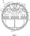
- Figure 2 is a cross-sectional, schematic view of the aircraft 100 indicated by view arrows 2 in Figure 1 .
- Figure 2 illustrates a simplified version of a portion of the aircraft fuselage 103 that includes an outer "first wall” 155.
- the fuselage 103 includes a floor 150, ceiling 151, insulation layer 162, and aesthetic fascia walls 152.
- one or more of the ceiling 151, insulation layer 162, luggage compartment 127, aesthetic fascia walls 152, ducting, equipment, rack, and various other walls within the first wall 155 represent a "second wall” 162 of the aircraft 100.
- the cabin 153 is formed within the second wall 162 and includes seats 154, aisles, and various other components for the passengers.
- Structural members 160 are positioned at the first wall 155 of the aircraft 100.
- One aspect includes the structural members 160 being support beams that extend outward from the first wall 155.
- Support members 161 are attached to the structural members 160 to support various components which can include luggage compartments 157, the ceiling 151, fascia walls 152, ducting, equipment, and racks.
- the second wall 162 can include a variety of constructions.
- One aspect includes the second wall 162 being the insulation layer 162.
- Other aspects include the second wall 162 being a fascia wall 152, structural wall, and luggage compartment wall 157.
- the temperature of the first wall 155 eventually decreases to a temperature below the freezing temperature of water.
- This cooling causes the moisture 180 (e.g., water) to condense out of the air in the space 163 and freeze onto the inner surface of the first wall 155 as ice 181.
- the ice 181 begins to melt causing water droplets 182 to form that travel through the space 163 towards a bottom 164 of the fuselage 103.
- Some water droplets 182 enter gaps in the insulation layer 162, particularly where the support members 161 are attached to the structural members 160.
- Moisture diverting devices 10 are attached to the support members 161 to divert the moisture, i.e., the water droplets 182.
- the diverting of the moisture includes capturing the leaked moisture, retaining the captured moisture in the device 10, and expelling the moisture through evaporation.
- the devices 10 extend around the support members 161 and are configured to be positioned at the ends of the support members 161 where they attach to the structural members 160.
- the devices 10 include a first portion that absorbs the moisture and a second portion that allows for the moisture to evaporate.
- the devices 10 are further configured to be prefabricated and preassembled onto the support members 161 prior to the attachment of the support members 161 to the structural members 160. Once the support member 161 is connected to the structural member 160 during assembly, the device 10 can be moved along the support member 161 and into position to divert the moisture.
- Figure 3 illustrates a device 10 configured to be attached to one of the support members 161.
- the device 10 includes a first portion 20, a second portion 30, and a flexible and/or elastic band 40.
- the first and second portions 20, 30 are attached together such that water that is initially absorbed by the first portion 20 is subsequently moved to the second portion 30 where it evaporates.
- the band 40 can be attached to the first and/or second portions 20, 30, or can be a separate member that is positioned over the first and/or second portions 20, 30.
- the band 40 is configured to apply a compressive force to hold the device 10 onto the support member 161 at the desired position.
- the different portions 20, 30 of the device 10 function to divert the moisture from the support member 161.
- the first portion 20 captures the moisture through its shape and moisture absorbing material.
- the captured moisture is initially retained in the first portion 20 and subsequently transferred to the second portion 30.
- the second portion 30 receives the moisture and is fabricated from a material and shaped for the moisture to evaporate.
- the first portion 20 includes a first end 21 and a second end 22.
- An opening 23 (also referred to as a first opening 23) extends through the first portion 20 and is sized to receive the support member 161.
- the first portion 20 is shaped with the first end 21 having a larger diameter B1 than a diameter B2 of the second end 22.
- the first portion 20 has a tapered shape with the larger first end 21 that reduces to the smaller second end 22.
- the taper can be consistent along the length of the first portion 20 from the first end 21 to the second end 22 as illustrated in Figure 3 .
- Other tapered shapes can include but are not limited to a taper along a limited section of the length, and different sections of the length having different tapers.
- One aspect includes the first portion 20 with a frusto-conical shape.
- the first portion 20 can be constructed from a variety of different moisture absorbent materials, including but not limited to felt.
- the second portion 30 is positioned at the second end 22 of the first portion 20.
- the second portion 30 has a cylindrical shape with a first end 31 and opposing second end 32.
- the first end 31 can abut against the second end 22 of the first portion 20, or can overlap with the second end 22. In an overlapping arrangement, the first end 31 can be positioned within or on the outside of the second end 22.
- the amount of overlap between the portions 20, 30 can vary.
- the portions 20, 30 can be connected together in a variety of different manners, including but not limited to adhesive, bonding, heat staking, stitching, and mechanical fasteners.
- the first portion 20 is formed unitarily with the second portion 30.
- the second portion includes an opening 33 (also referred to as the second opening 33) that extends the length of the second portion 30.
- the opening 33 is configured to be aligned with the opening 23 of the first portion 20 and together are sized to receive the support member 161.
- the openings 23, 33 can have the same or different sizes.
- the second portion 30 can be fabricated from an elastic material to expand when placed on to the support member 161.
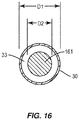
- One aspect as illustrated in Figure 16 includes the opening 33 with an inner diameter D1 that is 20% greater than the outer diameter D2 of the support member 161. Other aspects may include different sizes relative to the support member 161.
- the second portion 30 can be constructed from a variety of different evaporative materials, including but not limited to Nomex felt.
- the first portion 20 can be fabricated from the same or different material as the second portion 30.
- One aspect includes the portions 20, 30 each constructed from the same material.
- One specific aspect includes each portion 20, 30 fabricated from felt.
- first and second portions 20, 30 can include a single-layer construction.
- Figure 4 illustrates the first portion 20 with a single-layer.
- One or both of the portions 20, 30 can also include a multi-layer construction.
- Figure 4 illustrates the single construction of the first portion 20.
- the second portion 30 can include a similar single-layer construction, or can include two or more layers.
- the layers can be constructed from a single piece of material that is formed into the multiple layers, or can be formed by different material pieces.
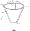
- Figure 5 illustrates a first portion 20 with multiple layers 24.
- the first portion 20 is formed by a single piece of moisture absorbent material 80 that is rolled into the multiple layers 24.
- the single piece of material 80 includes a leading edge 26 and a trailing edge 27.
- a majority of the first portion 20 includes a two-ply construction, with an overlap section 28 formed within the leading and trailing edges 26, 27 having a three-ply construction.
- the layers 24 are connected together at a connection seam 25 that extends along the length L within the overlap section 28.
- the connection seam 25 can be formed in a variety of manners, including adhesive, bonding, stitching, or mechanical fastener.
- the first portion 20 as illustrated in Figure 5 can be formed from a single flat piece of material 80.
- Figure 6 illustrates the single piece of material 80 prior to being rolled into the frusto-conical first portion 20.
- the material 80 has a coiled shape that extends between the first and second edges 26, 27.
- An open interior 29 forms the central opening 23 when shaped.
- the piece of material 80 includes different sections 60, 61, 62, 28 that include different inner and outer radii. The radii of the different sections 60, 61, 62, 28 provide for the flat piece of material 80 to be rolled into a frusto-conical shape having multiple layers 24 that lie against each other.
- One specific aspect provides for a first portion 20 with a frusto-conical shape having the following dimensions:
- the flat piece of material 80 includes the four sections 60, 61, 62, 28.
- the first section 60 extends 114° from the leading edge 26 and includes an outer radius R1 of 5.06 inches and an inner radius R4 of 1.90 inches.
- the second section 61 extends 114° from the first section 60 and includes an outer radius R2 of 5.38 inches and an inside radius R5 of 2.22 inches.
- a third section 62 extends 114° from the second section 61 and includes an outside radius R3 of 5.69 inches and an inside radius R6 of 2.53 inches.
- the overlap section 28 extends from the third section 62 and extends 14°.
- the overlap section 28 includes the same inside and outside radii as the third section 62.
- the different layers 24 of the first portion 20 can also be fabricated from multiple pieces of material that are attached together in an overlapping arrangement.
- the different pieces of material can be constructed from the same or different materials.
- the second portion 30 can be formed by one or more layers 34. With multiple layers 34, the layers 34 can be formed from a single piece of material 81 or multiple pieces of material 81. The different pieces of material 81 can be the same or different material.
- Figure 7 includes a second portion 30 with multiple layers 34 formed from a single piece of material 81.
- the piece of material 81 is rolled into the multiple layers 34 that extend around the central opening 33.
- Figure 7 includes a second portion 30 with two layers for a majority of the portion 30, with an overlap section 38 formed between the leading edge 36 and the trailing edge 37 having three layers.
- Connection seam 35 extends the length of the overlap section 38 to secure the layers 34 together.
- Connection seam 35 can be formed by a variety of manners, including adhesive, bonding, stitching, or mechanical fastener.
- the second portion 30 of Figure 7 is formed from a single piece of material 81.
- Figure 8 illustrates the piece of material 81 in a flat orientation prior to being formed into the cylindrical shape.
- the piece of material 81 includes a constant height and length between the edges 36, 37.
- the second portion 30 receives the liquid from the first portion 20 and provides for the liquid to evaporate.
- the second portion 30 can include configurations that expand an area of the outer surface 82.
- the second portion 30 can include one or more fins 39 that extend outward from the opening 33.
- the number of fins 39 along the second portion 30 can vary. Further, the fins 39 can include different shapes and/or sizes.
- Figure 9 includes the layers 34 including an inner layer 83 adjacent to the opening 33, and an outer layer 84 with fins 39.
- Figure 10 includes a second portion 30 with fins 39 formed by pleats in the piece of material 81 of the second portion 30.
- the fins 39 can be symmetrically aligned around the opening 33, or can be randomly placed.
- the fins 39 can be a single layer of material, or two or more layers.
- Figures 9 and 10 include the fins 39 fabricated as folded pleats of material.
- first and second portions 20, 30 can vary depending upon the specific contexts of use. This can include different shapes, dimensions, number of layers, and materials.
- the overall height of the device 10 is about seven inches.
- a height of the first portion 20 is about 3 inches, and the height of the second portion 30 is about 4 inches.
- the first and second portions 20, 30 overlap about 0.375 inches.
- the portions 20, 30 can be designed to accommodate the expected amount of moisture that will be encountered.
- the device 10 can be expected to absorb ten ounces of water within a predetermined period of time, such as during a flight.
- the first portion 20 is constructed to absorb this expected amount of moisture within the predetermined time period.
- the second portion 30 functions to allow the moisture to evaporate within a predetermined period of time. This can include that the moisture be evaporated within a certain number of hours after a flight.
- the construction parameters provide for a surface area of the second portion 30 to allow for evaporation of the expected amount of moisture. This can include type of material, size, and shape of the second portion 30.
- the band 40 maintains the first and second portions 20, 30 positioned on the support member 161. As illustrated in Figure 11 , the band 40 includes a central opening 41 that receives the second portion 30. The band 40 is flexible and applies a compressive force to the second portion 30 to maintain the positioning on the support member 161. The band 40 can be attached to the second portion 30 such as by an adhesive, bonding, stitching, or mechanical fastener.
- the band 40 applies the holding force to secure the position of the device 10 on the support member 161.
- the band 40 can include a smaller inner diameter than the outer diameter of the support member 161 such that the band 40 is stretched when the device 10 is assembled onto the support member 161.
- One aspect includes the inner diameter of the band 40 being 65% of the outer diameter of the support member 161. Thus, the band 40 is stretched and is able to apply a holding force.
- the device 10 can also include a flange 70 at the first end 21 of the first portion 20 to improve sealing against the insulation layer 162 and/or structural member 160.
- Figure 12 illustrates a device 10 with a flange 70 that includes an annular shape with a central opening 71 that is aligned with the opening 23 in the first portion 20.
- the flange 70 includes an outer diameter that is larger than the first portion 20.
- the inner diameter of the flange 71 can be equal to or smaller than that of the first portion 20.
- a moisture barrier 52 can also be attached to the outer surface 85 of the first portion 20 as illustrated in Figure 12 .
- the moisture barrier 52 substantially prevents the liquid from leaking from the first portion 20 prior to being moved to the second portion 30.
- the liquid barrier 52 assumes the tapered shape of the first portion 20. Liquid that escapes from the first portion 20 is captured by the liquid barrier 52 and funneled downward towards the second end 22 where it is transferred to the second portion 30.
- the moisture barrier 52 can be a film attached to the outer surface 85 of the first portion 20.
- the moisture barrier can also be a separate piece of material that is positioned on the exterior.
- the device 10 is prefabricated and then preassembled onto the support member 161. This reduces the time required by the worker installing the moisture treatment for the support member 161. The worker is merely required to position the device 10 along the support member 161 after installation, and is not required to also assemble the device 10 and attach the device 10 to the support member 161 prior to installation.
- Figure 13 illustrates a device 10 preassembled onto a support member 161.
- This preassembled support member 161 is provided to the worker who is tasked with the installation.
- the device 10 is spaced away from an end 165 of the of the support member 161 and over an inner section 169 of the support member 161 that is spaced away from the end 165.
- the band 40 secures the device 10 to the support member 161, yet allows the worker to move the device 10 along the support member 161 as necessary as illustrated by arrows A.
- the device 10 is initially positioned along the support member 161 away from an end 165 that is to be attached to the vehicle. Once the end 165 is attached, the device 10 is moved along the support member 161 to extend over the end 165 to capture the moisture.
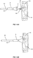
- Figures 14A and 14B illustrate use of the device 10.
- the support member 161 has been attached to the structural member 160.
- the end 165 of the support member 161 includes a receptacle that aligns with a connector 166 on the structural member 160.
- the connector 166 can include a clevis that is connected to the end 165 with a pin.
- the device 10 is positioned over an inner section 169 of the support member 161 away from the first end 165 such that it is out of the way of the worker.
- the device 10 is moved from the inner section 169 along the support member 161 and over the connection.
- the first end 21 of the first portion 20 is abutted against the structural member 160 and/or the insulation layer 162.
- the device 10 is thus positioned to capture the moisture with the first portion 20.
- the moisture is then transferred to the second portion 30 where it is evaporated from the device 10.
- the band 40 is positioned over the second portion 30 and secures the device 10 in position along the support member 161.
- the band 40 also provides for the device 10 to be moved along the support member 161 as needed. As illustrated in Figures 14A and 14B , the device 10 can be moved in a first direction towards the structural member 160 to be positioned over the end 165. The device 10 can also be moved along the support member 161 in the opposing direction away from the structural member 160. This provides for accessing the end 165, connector 166, structural member 160, insulation layer 162, or other component in this area, such as during maintenance. Once the task is completed, the device 10 can be moved back over the first end 165.
- the band 40 allows for the movement while the device 10 remains positioned around the support member 161.
- Figure 15 illustrates the steps of a method of using the device 10 to divert moisture from the support member 161.
- the method includes positioning a first end 165 of the support member 161 at a structural member 160 (box 200).
- the device 10 is preassembled onto the member 161 and extends around the support member 161.
- the device 10 is also positioned along the support member 161 away from the first end 165.
- the first end 165 of the support member 161 is then connected to the structural member while the device 10 is attached and positioned away from the first end 165 (box 202).
- the device 10 is moved along the support member 161while the device 10 remains around the support member 161 (box 204).
- the device 10 is positioned with a first portion 20 that is fabricated from a moisture absorbent material over the first end 165 that is attached to the structural member, and a second portion 30 of the device 10 that is coupled to the first portion 20 is positioned away from the first end 165.
- the second portion 30 is fabricated from an evaporative material.
- the device 10 can be prefabricated and preassembled onto the support member 161 prior to being given to the worker that installs the support member 161. These processes can occur earlier in a separate assembly operation or can occur at the vendor who supplies the support member 161.
- the first portion 20 can include a frusto-conical shape prior to positioning over the end of the support member 161. During the positioning, the first portion 20 can be deformed and manipulated into different shapes to conform to the specific structural components in the vehicle. This can include deforming the first portion 20 to fit around the insulation layer 162.
- Figure 2 includes the device 10 being used along the support members 161 between the first wall 155 and the second wall 162 which in Figure 2 includes the insulation layer 162.
- the device 10 can also be used at other locations in the aircraft, including but not limited to on the opposing side of the insulation layer 162and on the opposing end of the support members 161 such as where it connects with a fascia wall 152 or a luggage compartment 157.
- the devices 10 can be used in a wide variety of locations and on a wide variety of vehicles.
- Vehicles 100 include but are not limited to manned aircraft, unmanned aircraft, manned spacecraft, unmanned spacecraft, manned rotorcraft, unmanned rotorcraft, satellites, rockets, missiles, manned terrestrial vehicles, unmanned terrestrial vehicles, manned surface water borne vehicles,, unmanned surface water borne vehicles, manned sub-surface water borne vehicles, unmanned sub-surface water borne vehicles, and combinations thereof.
Landscapes
- Engineering & Computer Science (AREA)
- Mechanical Engineering (AREA)
- Aviation & Aerospace Engineering (AREA)
- Air-Conditioning For Vehicles (AREA)
- Drying Of Solid Materials (AREA)
- Drying Of Gases (AREA)
Abstract
Description
- The present disclosure generally relates to moisture control. More particularly, the present disclosure relates to devices and methods for diverting moisture from a support member in a vehicle.
- In an aircraft, the outer skin is spaced from the walls and ceiling of a passenger cabin (or other compartment), and the gap is at least partially filled with an insulation layer. The insulation layer is typically formed from a waterproof material. During a flight, liquid from moist air can condense against the skin and freeze during cruise. During decent, this frozen liquid can thaw and drip back down towards the cabin. Because the insulation layer is waterproof, the condensate can flow along the insulation layer and drain into the bilge. However, at some locations, structures and/or supports can protrude through the insulation layer. For example, support members that hold monuments and bins to the crown extend from the structure at the skin, through the insulation layer, and into the cabin. The insulation layers come with predefined holes for the support members to extend through the insulation layer. The holes are lined, and there can be a gap defined between the inner surface of the hole and the support member. When liquid thaws, it can drip down through the hole and into the cabin.
- One current practice is to manually wrap the support member with a material so the material absorbs the condensate and allows the condensate to evaporate back into the air. However, the condensate can be more than the material can absorb. Further, manually wrapping each support in material after the support member is installed in the aircraft can be time-consuming. More specifically, as the support members are often located in the overhead portion of the aircraft it is time consuming for a technician, working overhead, to manually wrap the support members.
- The present application includes a moisture diverting device for use with a support member. The moisture diverting device provides for absorbing and evaporating the moisture. The device is further configured to be prefabricated and preassembled onto the support member prior to installation onto the vehicle.
- One aspect is directed to a device to divert moisture from a support member. The device includes a first portion with a leading edge, a trailing edge, and a first opening that extends between the edges and that is sized to receive the member. The first portion is fabricated from a moisture absorbent material. A second portion is positioned at the trailing edge of the first portion. The second portion has a second opening that is aligned with the first opening to receive the member. The second portion is fabricated from an evaporative material. The second portion is coupled to the first portion such that the moisture absorbed by the first portion is transmitted to and evaporated by the second portion.
- Another aspect is directed to a method of diverting moisture from a support member. The method includes positioning a first end of a support member at a structural member with the support member including a moisture diverting device that extends around the support member and is attached to the support member away from the first end. The method includes connecting the first end of the support member to the structural member while the moisture diverting device is attached to the support member and positioned away from the first end. The method includes moving the moisture diverting device along the support member while the moisture diverting device remains around the support member. A first portion that is fabricated from a moisture absorbent material is positioned over the first end of the support member that is attached to the structural member. A second portion of the device that is coupled to the first portion is positioned away from the first end of the support member with the second portion fabricated from an evaporative material.
- Another aspect is directed to a vehicle with a first wall, and a second wall positioned within and spaced away from the first wall. A structural member is positioned between the first and second walls. A support member at the second wall and that has an end connected to the structural member. A moisture diverting device is attached to the support member and extends over the end of the support member to divert moisture away from the support member. The moisture diverting device includes a first portion with a leading edge, a trailing edge, and a first opening that extends between the edges and that is sized to receive the member with the first portion fabricated from a moisture absorbent material. The moisture diverting device also includes a second portion positioned at the trailing edge of the first portion with the second portion having a second opening that is aligned with the first opening to receive the member and with the second portion fabricated from an evaporative material. The second portion is coupled to the first portion such that the moisture absorbed by the first portion is transmitted to and evaporated by the second portion.
-
-
Figure 1 is a perspective view of a vehicle. -
Figure 2 is a schematic section view of the vehicle ofFigure 1 cut along the line II-II. -
Figure 3 is a perspective view of a moisture diverting device. -
Figure 4 is a section view cut along line IV-IV ofFigure 3 . -
Figure 5 is a perspective view of a first portion of a moisture diverting device. -
Figure 6 is a plan view of a material piece in a flat configuration. -
Figure 7 is a perspective view of a second portion of a moisture diverting device. -
Figure 8 is a plan view of a material piece in a flat configuration. -
Figure 9 is a perspective view of a second portion of a moisture diverting device. -
Figure 10 is a perspective view of a second portion of a moisture diverting device. -
Figure 11 is a perspective view of a band of a moisture diverting device. -
Figure 12 is a perspective view of a moisture diverting device. -
Figure 13 is a side view of a moisture diverting device attached to a support member. -
Figure 14A is a side view of a moisture diverting device attached to a first section of a support member. -
Figure 14B is a side view of a moisture diverting device attached to a second section of a support member. -
Figure 15 is a flowchart of a method of diverting moisture from a support member. -
Figure 16 is a section view cut along line XVI-XVI ofFigure 13 . - The present application is directed to devices and methods to control the moisture at a support member in a vehicle. The devices are configured to be attached to the support member and include a moisture absorbing portion and an evaporative portion. Methods of assembling the support member in the vehicle include prefabricating the device and assembling the device onto the support member prior to the support member being installed in the vehicle.
- The devices and methods apply to a variety of different vehicles.
Figure 1 illustrates anaircraft 100 which is one of the types ofvehicles 100 applicable to the devices and methods. Theaircraft 100 includes anose 101,wings 102, afuselage 103, and atail 104.Figure 1 also illustrates adownward arrow 105 indicating the expected direction in which the force of gravity will pull objects, such as liquid water, onboard anaircraft 100 in a nominal operational profile. -
Figure 2 is a cross-sectional, schematic view of theaircraft 100 indicated by view arrows 2 inFigure 1 .Figure 2 illustrates a simplified version of a portion of theaircraft fuselage 103 that includes an outer "first wall" 155. Thefuselage 103 includes afloor 150,ceiling 151,insulation layer 162, andaesthetic fascia walls 152. For purposes of explanation, one or more of theceiling 151,insulation layer 162, luggage compartment 127,aesthetic fascia walls 152, ducting, equipment, rack, and various other walls within thefirst wall 155 represent a "second wall" 162 of theaircraft 100. Thecabin 153 is formed within thesecond wall 162 and includesseats 154, aisles, and various other components for the passengers.Structural members 160 are positioned at thefirst wall 155 of theaircraft 100. One aspect includes thestructural members 160 being support beams that extend outward from thefirst wall 155.Support members 161 are attached to thestructural members 160 to support various components which can includeluggage compartments 157, theceiling 151,fascia walls 152, ducting, equipment, and racks. - Respiration and other sources of
water cause moisture 180 to enter or form in the air in thecabin 153. For example, warm exhaled air includesmoisture 180 and rises upward through the luggage compartments 157. Some of this warm and moist air rises through theceiling 151. Furthermore, some warm air continues to rise upward through thesecond wall 162 into aspace 163 between thefirst wall 155 and thesecond wall 162 of theaircraft 100. Thesecond wall 162 can include a variety of constructions. One aspect includes thesecond wall 162 being theinsulation layer 162. Other aspects include thesecond wall 162 being afascia wall 152, structural wall, andluggage compartment wall 157. - As the
first wall 155 is cooled by the outside air at high altitude during flight, the temperature of thefirst wall 155 eventually decreases to a temperature below the freezing temperature of water. This cooling causes the moisture 180 (e.g., water) to condense out of the air in thespace 163 and freeze onto the inner surface of thefirst wall 155 asice 181. As the temperature increases when theaircraft 100 changes to a lower altitude and/or commences descent for landing, theice 181 begins to melt causingwater droplets 182 to form that travel through thespace 163 towards abottom 164 of thefuselage 103. Somewater droplets 182 enter gaps in theinsulation layer 162, particularly where thesupport members 161 are attached to thestructural members 160. -
Moisture diverting devices 10 are attached to thesupport members 161 to divert the moisture, i.e., thewater droplets 182. The diverting of the moisture includes capturing the leaked moisture, retaining the captured moisture in thedevice 10, and expelling the moisture through evaporation. - The
devices 10 extend around thesupport members 161 and are configured to be positioned at the ends of thesupport members 161 where they attach to thestructural members 160. Thedevices 10 include a first portion that absorbs the moisture and a second portion that allows for the moisture to evaporate. Thedevices 10 are further configured to be prefabricated and preassembled onto thesupport members 161 prior to the attachment of thesupport members 161 to thestructural members 160. Once thesupport member 161 is connected to thestructural member 160 during assembly, thedevice 10 can be moved along thesupport member 161 and into position to divert the moisture. -
Figure 3 illustrates adevice 10 configured to be attached to one of thesupport members 161. Thedevice 10 includes afirst portion 20, asecond portion 30, and a flexible and/orelastic band 40. The first andsecond portions first portion 20 is subsequently moved to thesecond portion 30 where it evaporates. Theband 40 can be attached to the first and/orsecond portions second portions band 40 is configured to apply a compressive force to hold thedevice 10 onto thesupport member 161 at the desired position. - The
different portions device 10 function to divert the moisture from thesupport member 161. Thefirst portion 20 captures the moisture through its shape and moisture absorbing material. The captured moisture is initially retained in thefirst portion 20 and subsequently transferred to thesecond portion 30. Thesecond portion 30 receives the moisture and is fabricated from a material and shaped for the moisture to evaporate. - The
first portion 20 includes afirst end 21 and asecond end 22. An opening 23 (also referred to as a first opening 23) extends through thefirst portion 20 and is sized to receive thesupport member 161. Thefirst portion 20 is shaped with thefirst end 21 having a larger diameter B1 than a diameter B2 of thesecond end 22. In one aspect, thefirst portion 20 has a tapered shape with the largerfirst end 21 that reduces to the smallersecond end 22. The taper can be consistent along the length of thefirst portion 20 from thefirst end 21 to thesecond end 22 as illustrated inFigure 3 . Other tapered shapes can include but are not limited to a taper along a limited section of the length, and different sections of the length having different tapers. One aspect includes thefirst portion 20 with a frusto-conical shape. - The
first portion 20 can be constructed from a variety of different moisture absorbent materials, including but not limited to felt. - The
second portion 30 is positioned at thesecond end 22 of thefirst portion 20. Thesecond portion 30 has a cylindrical shape with afirst end 31 and opposingsecond end 32. Thefirst end 31 can abut against thesecond end 22 of thefirst portion 20, or can overlap with thesecond end 22. In an overlapping arrangement, thefirst end 31 can be positioned within or on the outside of thesecond end 22. The amount of overlap between theportions portions first portion 20 is formed unitarily with thesecond portion 30. - The second portion includes an opening 33 (also referred to as the second opening 33) that extends the length of the
second portion 30. Theopening 33 is configured to be aligned with theopening 23 of thefirst portion 20 and together are sized to receive thesupport member 161. Theopenings - The
second portion 30 can be fabricated from an elastic material to expand when placed on to thesupport member 161. One aspect as illustrated inFigure 16 includes theopening 33 with an inner diameter D1 that is 20% greater than the outer diameter D2 of thesupport member 161. Other aspects may include different sizes relative to thesupport member 161. Thesecond portion 30 can be constructed from a variety of different evaporative materials, including but not limited to Nomex felt. - The
first portion 20 can be fabricated from the same or different material as thesecond portion 30. One aspect includes theportions portion - One or both of the first and
second portions Figure 4 illustrates thefirst portion 20 with a single-layer. One or both of theportions Figure 4 illustrates the single construction of thefirst portion 20. Thesecond portion 30 can include a similar single-layer construction, or can include two or more layers. The layers can be constructed from a single piece of material that is formed into the multiple layers, or can be formed by different material pieces.Figure 5 illustrates afirst portion 20 withmultiple layers 24. In the exemplary embodiment, thefirst portion 20 is formed by a single piece of moistureabsorbent material 80 that is rolled into the multiple layers 24. The single piece ofmaterial 80 includes aleading edge 26 and a trailingedge 27. In thefirst portion 20 ofFigure 5 , a majority of thefirst portion 20 includes a two-ply construction, with anoverlap section 28 formed within the leading and trailingedges layers 24 are connected together at aconnection seam 25 that extends along the length L within theoverlap section 28. Theconnection seam 25 can be formed in a variety of manners, including adhesive, bonding, stitching, or mechanical fastener. - The
first portion 20 as illustrated inFigure 5 can be formed from a single flat piece ofmaterial 80.Figure 6 illustrates the single piece ofmaterial 80 prior to being rolled into the frusto-conicalfirst portion 20. Thematerial 80 has a coiled shape that extends between the first andsecond edges central opening 23 when shaped. The piece ofmaterial 80 includesdifferent sections different sections material 80 to be rolled into a frusto-conical shape havingmultiple layers 24 that lie against each other. - One specific aspect provides for a
first portion 20 with a frusto-conical shape having the following dimensions: - Height (measured between the first and second ends 21, 22): 3 inches Inside radius of first end 21: 1.6 inches
- Middle radius of first end 21: 1.7 inches
- Outside radius of first end 21:1.8 inches
- Inside radius of second end 22: 0.6 inches
- Middle radius of second end 22: 0.7 inches
- Outside radius of second end 22: 0.8 inches
- To achieve the
first portion 20 with this shape and size, the flat piece ofmaterial 80 includes the foursections first section 60 extends 114° from the leadingedge 26 and includes an outer radius R1 of 5.06 inches and an inner radius R4 of 1.90 inches. Thesecond section 61 extends 114° from thefirst section 60 and includes an outer radius R2 of 5.38 inches and an inside radius R5 of 2.22 inches. Athird section 62 extends 114° from thesecond section 61 and includes an outside radius R3 of 5.69 inches and an inside radius R6 of 2.53 inches. Theoverlap section 28 extends from thethird section 62 and extends 14°. Theoverlap section 28 includes the same inside and outside radii as thethird section 62. - The
different layers 24 of thefirst portion 20 can also be fabricated from multiple pieces of material that are attached together in an overlapping arrangement. The different pieces of material can be constructed from the same or different materials. - The
second portion 30 can be formed by one or more layers 34. Withmultiple layers 34, thelayers 34 can be formed from a single piece ofmaterial 81 or multiple pieces ofmaterial 81. The different pieces ofmaterial 81 can be the same or different material. -
Figure 7 includes asecond portion 30 withmultiple layers 34 formed from a single piece ofmaterial 81. The piece ofmaterial 81 is rolled into themultiple layers 34 that extend around thecentral opening 33.Figure 7 includes asecond portion 30 with two layers for a majority of theportion 30, with anoverlap section 38 formed between theleading edge 36 and the trailingedge 37 having three layers.Connection seam 35 extends the length of theoverlap section 38 to secure thelayers 34 together.Connection seam 35 can be formed by a variety of manners, including adhesive, bonding, stitching, or mechanical fastener. - The
second portion 30 ofFigure 7 is formed from a single piece ofmaterial 81.Figure 8 illustrates the piece ofmaterial 81 in a flat orientation prior to being formed into the cylindrical shape. The piece ofmaterial 81 includes a constant height and length between theedges - The
second portion 30 receives the liquid from thefirst portion 20 and provides for the liquid to evaporate. To facilitate the evaporation, thesecond portion 30 can include configurations that expand an area of theouter surface 82. To increase the area of theouter surface 82, thesecond portion 30 can include one ormore fins 39 that extend outward from theopening 33. The number offins 39 along thesecond portion 30 can vary. Further, thefins 39 can include different shapes and/or sizes.Figure 9 includes thelayers 34 including aninner layer 83 adjacent to theopening 33, and anouter layer 84 withfins 39.Figure 10 includes asecond portion 30 withfins 39 formed by pleats in the piece ofmaterial 81 of thesecond portion 30. Thefins 39 can be symmetrically aligned around theopening 33, or can be randomly placed. Thefins 39 can be a single layer of material, or two or more layers.Figures 9 and 10 include thefins 39 fabricated as folded pleats of material. - The dimensions and construction of the first and
second portions second portions single layer 34. The overall height of thedevice 10 is about seven inches. A height of thefirst portion 20 is about 3 inches, and the height of thesecond portion 30 is about 4 inches. The first andsecond portions - The
portions device 10 can be expected to absorb ten ounces of water within a predetermined period of time, such as during a flight. Thefirst portion 20 is constructed to absorb this expected amount of moisture within the predetermined time period. - Similarly, the
second portion 30 functions to allow the moisture to evaporate within a predetermined period of time. This can include that the moisture be evaporated within a certain number of hours after a flight. The construction parameters provide for a surface area of thesecond portion 30 to allow for evaporation of the expected amount of moisture. This can include type of material, size, and shape of thesecond portion 30. - The
band 40 maintains the first andsecond portions support member 161. As illustrated inFigure 11 , theband 40 includes a central opening 41 that receives thesecond portion 30. Theband 40 is flexible and applies a compressive force to thesecond portion 30 to maintain the positioning on thesupport member 161. Theband 40 can be attached to thesecond portion 30 such as by an adhesive, bonding, stitching, or mechanical fastener. - The
band 40 applies the holding force to secure the position of thedevice 10 on thesupport member 161. Theband 40 can include a smaller inner diameter than the outer diameter of thesupport member 161 such that theband 40 is stretched when thedevice 10 is assembled onto thesupport member 161. One aspect includes the inner diameter of theband 40 being 65% of the outer diameter of thesupport member 161. Thus, theband 40 is stretched and is able to apply a holding force. - The
device 10 can also include a flange 70 at thefirst end 21 of thefirst portion 20 to improve sealing against theinsulation layer 162 and/orstructural member 160.Figure 12 illustrates adevice 10 with a flange 70 that includes an annular shape with acentral opening 71 that is aligned with theopening 23 in thefirst portion 20. The flange 70 includes an outer diameter that is larger than thefirst portion 20. The inner diameter of theflange 71 can be equal to or smaller than that of thefirst portion 20. - A
moisture barrier 52 can also be attached to theouter surface 85 of thefirst portion 20 as illustrated inFigure 12 . Themoisture barrier 52 substantially prevents the liquid from leaking from thefirst portion 20 prior to being moved to thesecond portion 30. Theliquid barrier 52 assumes the tapered shape of thefirst portion 20. Liquid that escapes from thefirst portion 20 is captured by theliquid barrier 52 and funneled downward towards thesecond end 22 where it is transferred to thesecond portion 30. Themoisture barrier 52 can be a film attached to theouter surface 85 of thefirst portion 20. The moisture barrier can also be a separate piece of material that is positioned on the exterior. - In use, the
device 10 is prefabricated and then preassembled onto thesupport member 161. This reduces the time required by the worker installing the moisture treatment for thesupport member 161. The worker is merely required to position thedevice 10 along thesupport member 161 after installation, and is not required to also assemble thedevice 10 and attach thedevice 10 to thesupport member 161 prior to installation. -
Figure 13 illustrates adevice 10 preassembled onto asupport member 161. Thispreassembled support member 161 is provided to the worker who is tasked with the installation. As illustrated inFigure 13 , thedevice 10 is spaced away from anend 165 of the of thesupport member 161 and over aninner section 169 of thesupport member 161 that is spaced away from theend 165. Theband 40 secures thedevice 10 to thesupport member 161, yet allows the worker to move thedevice 10 along thesupport member 161 as necessary as illustrated by arrows A. - As illustrated in
Figure 13 , thedevice 10 is initially positioned along thesupport member 161 away from anend 165 that is to be attached to the vehicle. Once theend 165 is attached, thedevice 10 is moved along thesupport member 161 to extend over theend 165 to capture the moisture. -
Figures 14A and 14B illustrate use of thedevice 10. As illustrated inFigure 14A , thesupport member 161 has been attached to thestructural member 160. Specifically, theend 165 of thesupport member 161 includes a receptacle that aligns with aconnector 166 on thestructural member 160. Theconnector 166 can include a clevis that is connected to theend 165 with a pin. During the attachment, thedevice 10 is positioned over aninner section 169 of thesupport member 161 away from thefirst end 165 such that it is out of the way of the worker. After thesupport member 161 is connected to thestructural member 160, thedevice 10 is moved from theinner section 169 along thesupport member 161 and over the connection. Thefirst end 21 of thefirst portion 20 is abutted against thestructural member 160 and/or theinsulation layer 162. Thedevice 10 is thus positioned to capture the moisture with thefirst portion 20. The moisture is then transferred to thesecond portion 30 where it is evaporated from thedevice 10. - The
band 40 is positioned over thesecond portion 30 and secures thedevice 10 in position along thesupport member 161. Theband 40 also provides for thedevice 10 to be moved along thesupport member 161 as needed. As illustrated inFigures 14A and 14B , thedevice 10 can be moved in a first direction towards thestructural member 160 to be positioned over theend 165. Thedevice 10 can also be moved along thesupport member 161 in the opposing direction away from thestructural member 160. This provides for accessing theend 165,connector 166,structural member 160,insulation layer 162, or other component in this area, such as during maintenance. Once the task is completed, thedevice 10 can be moved back over thefirst end 165. Theband 40 allows for the movement while thedevice 10 remains positioned around thesupport member 161. -
Figure 15 illustrates the steps of a method of using thedevice 10 to divert moisture from thesupport member 161. The method includes positioning afirst end 165 of thesupport member 161 at a structural member 160 (box 200). Thedevice 10 is preassembled onto themember 161 and extends around thesupport member 161. Thedevice 10 is also positioned along thesupport member 161 away from thefirst end 165. Thefirst end 165 of thesupport member 161 is then connected to the structural member while thedevice 10 is attached and positioned away from the first end 165 (box 202). Once thesupport member 161 is connected, thedevice 10 is moved along the support member 161while thedevice 10 remains around the support member 161 (box 204). Thedevice 10 is positioned with afirst portion 20 that is fabricated from a moisture absorbent material over thefirst end 165 that is attached to the structural member, and asecond portion 30 of thedevice 10 that is coupled to thefirst portion 20 is positioned away from thefirst end 165. Thesecond portion 30 is fabricated from an evaporative material. - The
device 10 can be prefabricated and preassembled onto thesupport member 161 prior to being given to the worker that installs thesupport member 161. These processes can occur earlier in a separate assembly operation or can occur at the vendor who supplies thesupport member 161. - The
first portion 20 can include a frusto-conical shape prior to positioning over the end of thesupport member 161. During the positioning, thefirst portion 20 can be deformed and manipulated into different shapes to conform to the specific structural components in the vehicle. This can include deforming thefirst portion 20 to fit around theinsulation layer 162. -
Figure 2 includes thedevice 10 being used along thesupport members 161 between thefirst wall 155 and thesecond wall 162 which inFigure 2 includes theinsulation layer 162. Thedevice 10 can also be used at other locations in the aircraft, including but not limited to on the opposing side of the insulation layer 162and on the opposing end of thesupport members 161 such as where it connects with afascia wall 152 or aluggage compartment 157. Thedevices 10 can be used in a wide variety of locations and on a wide variety of vehicles. - The
device 10 can be used on a variety ofvehicles 100.Vehicles 100 include but are not limited to manned aircraft, unmanned aircraft, manned spacecraft, unmanned spacecraft, manned rotorcraft, unmanned rotorcraft, satellites, rockets, missiles, manned terrestrial vehicles, unmanned terrestrial vehicles, manned surface water borne vehicles,, unmanned surface water borne vehicles, manned sub-surface water borne vehicles, unmanned sub-surface water borne vehicles, and combinations thereof. - Further, the disclosure comprises embodiments according to the following clauses:
- Clause 1. A device to divert moisture from a support member, the device comprising:
- a first portion with a first end, a second end, and a first opening that extends between the ends and that is sized to receive the support member, the first portion fabricated from a moisture absorbent material; and
- a second portion positioned at the second end of the first portion, the second portion having a second opening that is aligned with the first opening to receive the support member, the second portion fabricated from an evaporative material,
- the second portion coupled to the first portion such that the moisture absorbed by the first portion is transmitted to and evaporated by the second portion.
- Clause 2. The device of clause 1, wherein the first portion comprises the moisture absorbent material that extends around the first opening in multiple layers based on a predetermined moisture capacity, and the second portion comprises the evaporative material that extends around the second opening in multiple layers based on a predetermined evaporative time.
- Clause 3. The device of clause 1 or 2, wherein the first portion has a conical shape with the first end having a larger diameter than the second end.
- Clause 4. The device of any preceding clause, wherein the second portion has a cylindrical shape.
- Clause 5. The device of any preceding clause, wherein an outer layer of the second portion comprises one or more fins that extend radially outward away from the second opening.
- Clause 6. The device of any preceding clause, further comprising a moisture barrier positioned on an outer surface of the first portion.
- Clause 7. The device of any preceding clause, further comprising a flexible band that extends around an outer surface of the second portion and is configured to secure the device to the support member.
- Clause 8. The device of any preceding clause, wherein the first and second openings are coaxially aligned.
- Clause 9. A method of diverting moisture from a support member, the method comprising:
- positioning a first end of a support member at a structural member, the support member comprising a moisture diverting device that extends around the support member and is attached to the support member away from the first end;
- connecting the first end of the support member to the structural member while the moisture diverting device is attached to the support member and positioned away from the first end; and
- moving the moisture diverting device along the support member while the moisture diverting device remains around the support member and positioning a first portion of the moisture diverting device that is fabricated from a moisture absorbent material over the first end of the support member that is attached to the structural member while positioning a second portion of the device that is coupled to the first portion away from the first end of the support member with the second portion fabricated from an evaporative material.
-
Clause 10. The method of clause 9, further comprising:- absorbing the moisture with the first portion of the moisture diverting device;
- transmitting the moisture from the first portion to the second portion of the moisture diverting device; and
- evaporating the moisture from the second portion of the moisture diverting device.
- Clause 11. The method of
clause 9 or 10, further comprising abutting the first portion of the moisture diverting device against an insulation layer that is positioned at the structural member such that the first portion is spaced away from the structural member. - Clause 12. The method of
clause 9, 10 or 11, further comprising securing the moisture diverting device over the first end of the support member with an elastic band that is on the second portion of the moisture diverting device. - Clause 13. The method of any of
clauses 10 to 12, further comprising after evaporating the moisture from the second portion, moving the moisture diverting device along the support member and away from the first end of the support member and exposing the first end of the support member. - Clause 14. The method of clause 13, wherein moving the moisture diverting device along the support member and away from the first end of the support member comprises sliding the moisture diverting device along the support member while the moisture diverting device extends around the moisture diverting device.
- Clause 15. The method of any of clauses 9 to 14, further comprising coupling the first portion and the second portion of the moisture diverting device together prior to attaching the moisture diverting device to the structural member.
- Clause 16. The method of any of clauses 9 to 15, further comprising connecting the first end of the support member to a clevis on the structural member.
- Clause 17. The method of any of clauses 9 to 16, further comprising positioning the first portion of the moisture diverting device that has a conical shape over the first end of the support member and positioning the second portion of the moisture diverting device that has a cylindrical shape over an inner section of the support member away from the first end of the support member.
- Clause 18. The method of any of clauses 9 to 17, further comprising positioning an inner layer of the second portion of the moisture diverting device against the support member and facing an outer layer outward away from the support member with each of the inner and outer layers being formed from a common piece.
- Clause 19. A vehicle comprising:
- a first wall;
- a second wall positioned within and spaced away from the first wall;
- a structural member positioned between the first and second walls;
- a support member at the second wall and that includes an end connected to the structural member; and
- a moisture diverting device attached to the support member and extending over the end of the support member to divert moisture away from the support member, the moisture diverting device comprising:
- a first portion with a first end, a second end, and a first opening that extends between the ends and that is sized to receive the support member, the first portion fabricated from a moisture absorbent material; and
- a second portion positioned at the second end of the first portion, the second portion having a second opening that is aligned with the first opening to receive the support member, the second portion fabricated from an evaporative material;
- the second portion coupled to the first portion such that the moisture absorbed by the first portion is transmitted to and evaporated by the second portion.
-
Clause 20. The vehicle of clause 19, wherein the vehicle is selected from the group consisting essentially of an aircraft, a spacecraft, a rotorcraft, a satellite, a rocket, a missile, a terrestrial vehicle, a surface water borne vehicle, and a sub-surface water borne vehicle. - The present disclosure can be carried out in other ways than those specifically set forth herein without departing from essential characteristics of the disclosure. The present aspects are to be considered in all respects as illustrative and not restrictive, and all changes coming within the meaning and equivalency range of the appended claims are intended to be embraced therein.
Claims (15)
- A device (10) to divert moisture from a support member (161), the device (10) comprising:a first portion (20) with a first end (21), a second end (22), and a first opening (23) that extends between the first and second ends (21,22) and that is sized to receive the support member (161), the first portion (20) fabricated from a moisture absorbent material (80); anda second portion (30) positioned at the second end (22) of the first portion (20), the second portion (30) having a second opening (33) that is aligned with the first opening (23) to receive the support member (161), the second portion (30) fabricated from an evaporative material,the second portion (30) coupled to the first portion (20) such that the moisture absorbed by the first portion (20) is transmitted to and evaporated by the second portion (30).
- The device (10) of claim 1, wherein the first portion (20) comprises the moisture absorbent material (80) that extends around the first opening (23) in multiple layers (24) based on a predetermined moisture capacity, and the second portion (30) comprises the evaporative material that extends around the second opening (33) in multiple layers (36) based on a predetermined evaporative time.
- The device (10) of any of claims 1 to 2, wherein the first portion (20) has a conical shape with the first end (21) having a larger diameter than the second end (22).
- The device (10) of any of claims 1 to 3, wherein the second portion (30) has a cylindrical shape.
- The device (10) of any of claims 1 to 4, wherein an outer layer (84) of the second portion (30) comprises one or more fins (39) that extend radially outward away from the second opening (33).
- The device (10) of any of claims 1 to 5, further comprising a moisture barrier (52) positioned on an outer surface (85) of the first portion (20).
- The device (10) of any of claims 1 to 6, further comprising a flexible band that extends around an outer surface (82) of the second portion (30) and is configured to secure the device (10) to the support member (161).
- The device (10) of any of claims 1 to 7, wherein the first and second openings (23, 33) are coaxially aligned.
- A method of diverting moisture from a support member (161), the method comprising:positioning a first end (165) of a support member (161) at a structural member (160), the support member (161) comprising a moisture diverting device (10) that extends around the support member (161) and is attached to the support member (161) away from the first end (165) of the support member (161);connecting the first end (165) of the support member (161) to the structural member (160) while the moisture diverting device (10) is attached to the support member (161) and positioned away from the first end (165); andmoving the moisture diverting device (10) along the support member (161) while the moisture diverting device (10) remains around the support member (161) and positioning a first portion (20) of the moisture diverting device (10) that is fabricated from a moisture absorbent material (80) over the first end (165) of the support member (161) that is attached to the structural member (160) while positioning a second portion (30) of the moisture diverting device (10) is coupled to the first portion (20) away from the first end (165) of the support member (161) with the second portion (30) fabricated from an evaporative material.
- The method of claim 9, further comprising:absorbing the moisture with the first portion (20) of the moisture diverting device (10);transmitting the moisture from the first portion (20) to the second portion (30) of the moisture diverting device (10); andevaporating the moisture from the second portion (30) of the moisture diverting device (10).
- The method of any of claims 9 to 10, further comprising abutting the first portion (20) of the moisture diverting device (10) against an insulation layer that is positioned at the structural member (160) such that the first portion (20) is spaced away from the structural member (160).
- The method of any of claims 9 to 11, further comprising after evaporating the moisture from the second portion (30), moving the moisture diverting device (10) along the support member (161) and away from the first end (165) of the support member (161) and exposing the first end (165) of the support member (161), and optionally, wherein moving the moisture diverting device (10) along the support member (161) and away from the first end (165) of the support member (161) comprises sliding the moisture diverting device (10) along the support member (161) while the moisture diverting device (10) extends around the moisture diverting device (10).
- The method of any of claims 9 to 12, further comprising coupling the first portion (20) and the second portion (30) of the moisture diverting device (10) together prior to attaching the moisture diverting device (10) to the structural member (160) and securing the moisture diverting device (10) over the first end (165) of the support member (161) with an elastic band that is on the second portion (30) of the moisture diverting device (10).
- The method of any of claims 9 to 13, further comprising positioning the first portion (20) of the moisture diverting device (10) that has a conical shape over the first end (165) of the support member (161) and positioning the second portion (30) of the moisture diverting device (10) that has a cylindrical shape over an inner section of the support member (161) away from the first end (165) of the support member (161).
- The method of any of claims 9 to 14, further comprising positioning an inner layer (83) of the second portion (30) of the moisture diverting device (10) against the support member (161) and facing an outer layer (84) outward away from the support member (161) with each of the inner and outer layers (83,84) being formed from a common piece.
Applications Claiming Priority (1)
| Application Number | Priority Date | Filing Date | Title |
|---|---|---|---|
| US15/729,742 US11072411B2 (en) | 2017-10-11 | 2017-10-11 | Devices and methods for diverting moisture from a support member |
Publications (2)
| Publication Number | Publication Date |
|---|---|
| EP3470325A1 true EP3470325A1 (en) | 2019-04-17 |
| EP3470325B1 EP3470325B1 (en) | 2021-02-17 |
Family
ID=63762204
Family Applications (1)
| Application Number | Title | Priority Date | Filing Date |
|---|---|---|---|
| EP18196508.8A Active EP3470325B1 (en) | 2017-10-11 | 2018-09-25 | Devices and methods for diverting moisture from a support member |
Country Status (2)
| Country | Link |
|---|---|
| US (1) | US11072411B2 (en) |
| EP (1) | EP3470325B1 (en) |
Families Citing this family (3)
| Publication number | Priority date | Publication date | Assignee | Title |
|---|---|---|---|---|
| US11320296B2 (en) | 2020-03-30 | 2022-05-03 | The Boeing Company | Test cage for testing a gap in a vehicle |
| CN111483587B (en) * | 2020-04-16 | 2021-10-29 | 中国商用飞机有限责任公司 | Aircraft cabin ceiling unit with drying function |
| FR3113030B1 (en) * | 2020-07-31 | 2023-01-13 | Airbus Operations Sas | Insulating mattress with collection plate associated with a through hole for water evacuation |
Citations (5)
| Publication number | Priority date | Publication date | Assignee | Title |
|---|---|---|---|---|
| WO1991018237A1 (en) * | 1990-05-14 | 1991-11-28 | V.I.K.-Consult Aps | Insulation system and process for forming such an insulation system on a conduit or container |
| US5520009A (en) * | 1992-08-31 | 1996-05-28 | Rockwool International A/S | Method and apparatus for insulating |
| US20060016204A1 (en) * | 2004-07-21 | 2006-01-26 | Brokaw Matthew C | Insulation system with condensate wicking for vertical applications |
| DE102011001267A1 (en) * | 2011-03-15 | 2012-09-20 | Deutsches Zentrum für Luft- und Raumfahrt e.V. | Airliner, has hydrophilic manifold connected with hot gas source through connector, and outlet arranged at end of hydrophilic manifold, where end of manifold is turned away from connector of hot gas source |
| US20130344762A1 (en) * | 2011-01-25 | 2013-12-26 | Rns Technologies Bv | Insulation composition and method to detect water in an insulation composition |
Family Cites Families (20)
| Publication number | Priority date | Publication date | Assignee | Title |
|---|---|---|---|---|
| US2937036A (en) * | 1955-08-05 | 1960-05-17 | Lockheed Aircraft Corp | High temperature telescopic joint with heat insulating and radiating means |
| US4235398A (en) | 1978-12-18 | 1980-11-25 | The Boeing Company | Thermal insulation for aircraft fuselage |
| US5067291A (en) | 1990-06-08 | 1991-11-26 | Evensen Laurence P | Pass-through roof seal system |
| US5577688A (en) | 1994-06-15 | 1996-11-26 | Sloan; Frank P. | Containment systems for insulation, and insulation elements employing such systems |
| US5827598A (en) | 1996-11-05 | 1998-10-27 | The Boeing Company | Method and apparatus for sealing an aircraft penetration |
| US5788184A (en) | 1997-01-04 | 1998-08-04 | Eddy; Robert G. | Aircraft passenger safety enhanced fuselage insulation blanket |
| US6012480A (en) * | 1997-11-03 | 2000-01-11 | Helmsderfer; John A. | Cover assembly for covering undersink piping utilizing sliding cover pieces |
| US6315849B1 (en) | 1999-05-24 | 2001-11-13 | Grayling Industries, Inc. | Method of joining flexible sheets to tubes |
| US6531206B2 (en) | 2001-02-07 | 2003-03-11 | 3M Innovative Properties Company | Microstructured surface film assembly for liquid acquisition and transport |
| US20030024185A1 (en) | 2001-08-01 | 2003-02-06 | Menzies Samuel John | Apparatus and method for extending the length of a vent pipe above the elevation of a building roof |
| US6803090B2 (en) | 2002-05-13 | 2004-10-12 | 3M Innovative Properties Company | Fluid transport assemblies with flame retardant properties |
| US7159620B2 (en) * | 2002-09-04 | 2007-01-09 | Knauf Insulation Gmbh | Pipe blanket to fit a variety of pipe diameters |
| DE102005011531B4 (en) | 2005-03-10 | 2010-06-17 | Airbus Deutschland Gmbh | Structural element of an aircraft with a cavity |
| DE102010006564B4 (en) * | 2010-02-02 | 2016-01-28 | Airbus Operations Gmbh | Condensation pass reducing insulation package for thermal and acoustic insulation of a vehicle cabin and use of an insulating piece on a Isolierpaket and aircraft with a Isolierpaket |
| FR2967645B1 (en) | 2010-11-24 | 2013-08-30 | Airbus Operations Sas | DEVICE FOR SEALING BETWEEN A THROUGH ELEMENT AND AN INSULATION MATTRESS PROVIDED AT THE FUSELAGE OF AN AIRCRAFT, MATTRESS AND AIRCRAFT SO EQUIPPED |
| FR2977568B1 (en) * | 2011-07-06 | 2013-08-23 | Airbus Operations Sas | SYSTEM FOR DRAINING CONDENSING WATER IN AN AIRCRAFT |
| DE102011120762A1 (en) | 2011-12-09 | 2013-06-13 | Airbus Operations Gmbh | Cover device and aircraft area with cover device |
| DE102013009251A1 (en) * | 2013-06-03 | 2014-12-04 | Günter Bröker | Device for cutting material and cutting unit with oscillating cutting blade and variable cutting angle |
| US10451347B2 (en) * | 2016-06-22 | 2019-10-22 | The Boeing Company | Condensation-controlling insulation system and method |
| US9944379B2 (en) * | 2016-09-06 | 2018-04-17 | The Boeing Company | Moisture path close-out and thermal control system and methods of assembling same |
-
2017
- 2017-10-11 US US15/729,742 patent/US11072411B2/en active Active
-
2018
- 2018-09-25 EP EP18196508.8A patent/EP3470325B1/en active Active
Patent Citations (5)
| Publication number | Priority date | Publication date | Assignee | Title |
|---|---|---|---|---|
| WO1991018237A1 (en) * | 1990-05-14 | 1991-11-28 | V.I.K.-Consult Aps | Insulation system and process for forming such an insulation system on a conduit or container |
| US5520009A (en) * | 1992-08-31 | 1996-05-28 | Rockwool International A/S | Method and apparatus for insulating |
| US20060016204A1 (en) * | 2004-07-21 | 2006-01-26 | Brokaw Matthew C | Insulation system with condensate wicking for vertical applications |
| US20130344762A1 (en) * | 2011-01-25 | 2013-12-26 | Rns Technologies Bv | Insulation composition and method to detect water in an insulation composition |
| DE102011001267A1 (en) * | 2011-03-15 | 2012-09-20 | Deutsches Zentrum für Luft- und Raumfahrt e.V. | Airliner, has hydrophilic manifold connected with hot gas source through connector, and outlet arranged at end of hydrophilic manifold, where end of manifold is turned away from connector of hot gas source |
Also Published As
| Publication number | Publication date |
|---|---|
| US20190106191A1 (en) | 2019-04-11 |
| US11072411B2 (en) | 2021-07-27 |
| EP3470325B1 (en) | 2021-02-17 |
Similar Documents
| Publication | Publication Date | Title |
|---|---|---|
| EP3470325B1 (en) | Devices and methods for diverting moisture from a support member | |
| US5626310A (en) | Space launch vehicles configured as gliders and towed to launch altitude by conventional aircraft | |
| US6029928A (en) | Space launch vehicles configured as gliders and towed to launch altitude by conventional aircraft | |
| EP0692424A2 (en) | Containment systems for insulation, and insulation elements employing such systems | |
| JP2018513809A (en) | Aircraft for aerial delivery | |
| US20120025006A1 (en) | In-line staged horizontal takeoff and landing space plane | |
| US20030089821A1 (en) | Payload delivery system | |
| EP3170741B1 (en) | Aircraft bay blankets that provide enhanced drainage features | |
| US20170144761A1 (en) | Detachable Pilotable Capsules and Aircrafts Including Detachable Pilotable Capsules | |
| US10875620B2 (en) | Moisture path close-out and thermal control system and methods of assembling same | |
| GB2499897A (en) | Pod structure | |
| CA3014445C (en) | Devices and methods to capture moisture from a structural member | |
| DE10119221B4 (en) | Concealed encapsulated air ammunition ejection system | |
| US5660357A (en) | Airstream ejected missile engine inlet cover | |
| RU2207968C2 (en) | Multi-purpose highly manoeuvrable supersonic aircraft, its airframe, equipment and systems | |
| US11091270B2 (en) | Buoyancy driven passive vehicle air drying system and method | |
| US20170001703A1 (en) | Aircraft external part with inflatable panels | |
| EP0631931B1 (en) | Spacecraft with an escape system for the crew | |
| RU2353546C2 (en) | Mobile aircraft rocket-and-space system | |
| US6776375B1 (en) | Payload deployment system with an internal cargo unit | |
| US12240603B1 (en) | Oblique all-wing vehicle | |
| EP4065467B1 (en) | Casing of an aircraft | |
| RU2548829C2 (en) | Transport aircraft for space rockets carrying and acceleration in stratosphere | |
| RU2005102906A (en) | HORIZONTAL TAKE-OFF Rocket Launcher WITHOUT ANTIME WITH LOW-TEMPERATURE PLANNING IN THE ATMOSPHERE WITH SOFT GROUNDING OF THE VITYAZ RGV | |
| RU2636447C2 (en) | Aircraft rocket launch site formed on basis of space-mission vehicle adapted from topol-m icbm and carrier aircraft il-76mf for insertion of small spacecrafts into final orbits by inserting smv from aircraft using combined transport-launching platform and lifting-stabilizing parachute |
Legal Events
| Date | Code | Title | Description |
|---|---|---|---|
| PUAI | Public reference made under article 153(3) epc to a published international application that has entered the european phase |
Free format text: ORIGINAL CODE: 0009012 |
|
| STAA | Information on the status of an ep patent application or granted ep patent |
Free format text: STATUS: REQUEST FOR EXAMINATION WAS MADE |
|
| 17P | Request for examination filed |
Effective date: 20180925 |
|
| AK | Designated contracting states |
Kind code of ref document: A1 Designated state(s): AL AT BE BG CH CY CZ DE DK EE ES FI FR GB GR HR HU IE IS IT LI LT LU LV MC MK MT NL NO PL PT RO RS SE SI SK SM TR |
|
| AX | Request for extension of the european patent |
Extension state: BA ME |
|
| GRAP | Despatch of communication of intention to grant a patent |
Free format text: ORIGINAL CODE: EPIDOSNIGR1 |
|
| STAA | Information on the status of an ep patent application or granted ep patent |
Free format text: STATUS: GRANT OF PATENT IS INTENDED |
|
| GRAJ | Information related to disapproval of communication of intention to grant by the applicant or resumption of examination proceedings by the epo deleted |
Free format text: ORIGINAL CODE: EPIDOSDIGR1 |
|
| STAA | Information on the status of an ep patent application or granted ep patent |
Free format text: STATUS: REQUEST FOR EXAMINATION WAS MADE |
|
| INTG | Intention to grant announced |
Effective date: 20200622 |
|
| INTC | Intention to grant announced (deleted) | ||
| GRAP | Despatch of communication of intention to grant a patent |
Free format text: ORIGINAL CODE: EPIDOSNIGR1 |
|
| STAA | Information on the status of an ep patent application or granted ep patent |
Free format text: STATUS: GRANT OF PATENT IS INTENDED |
|
| INTG | Intention to grant announced |
Effective date: 20200915 |
|
| GRAS | Grant fee paid |
Free format text: ORIGINAL CODE: EPIDOSNIGR3 |
|
| GRAA | (expected) grant |
Free format text: ORIGINAL CODE: 0009210 |
|
| STAA | Information on the status of an ep patent application or granted ep patent |
Free format text: STATUS: THE PATENT HAS BEEN GRANTED |
|
| AK | Designated contracting states |
Kind code of ref document: B1 Designated state(s): AL AT BE BG CH CY CZ DE DK EE ES FI FR GB GR HR HU IE IS IT LI LT LU LV MC MK MT NL NO PL PT RO RS SE SI SK SM TR |
|
| REG | Reference to a national code |
Ref country code: GB Ref legal event code: FG4D |
|
| REG | Reference to a national code |
Ref country code: CH Ref legal event code: EP |
|
| REG | Reference to a national code |
Ref country code: DE Ref legal event code: R096 Ref document number: 602018012569 Country of ref document: DE |
|
| REG | Reference to a national code |
Ref country code: AT Ref legal event code: REF Ref document number: 1361134 Country of ref document: AT Kind code of ref document: T Effective date: 20210315 |
|
| REG | Reference to a national code |
Ref country code: IE Ref legal event code: FG4D |
|
| REG | Reference to a national code |
Ref country code: LT Ref legal event code: MG9D |
|
| REG | Reference to a national code |
Ref country code: NL Ref legal event code: MP Effective date: 20210217 |
|
| PG25 | Lapsed in a contracting state [announced via postgrant information from national office to epo] |
Ref country code: FI Free format text: LAPSE BECAUSE OF FAILURE TO SUBMIT A TRANSLATION OF THE DESCRIPTION OR TO PAY THE FEE WITHIN THE PRESCRIBED TIME-LIMIT Effective date: 20210217 Ref country code: HR Free format text: LAPSE BECAUSE OF FAILURE TO SUBMIT A TRANSLATION OF THE DESCRIPTION OR TO PAY THE FEE WITHIN THE PRESCRIBED TIME-LIMIT Effective date: 20210217 Ref country code: GR Free format text: LAPSE BECAUSE OF FAILURE TO SUBMIT A TRANSLATION OF THE DESCRIPTION OR TO PAY THE FEE WITHIN THE PRESCRIBED TIME-LIMIT Effective date: 20210518 Ref country code: BG Free format text: LAPSE BECAUSE OF FAILURE TO SUBMIT A TRANSLATION OF THE DESCRIPTION OR TO PAY THE FEE WITHIN THE PRESCRIBED TIME-LIMIT Effective date: 20210517 Ref country code: LT Free format text: LAPSE BECAUSE OF FAILURE TO SUBMIT A TRANSLATION OF THE DESCRIPTION OR TO PAY THE FEE WITHIN THE PRESCRIBED TIME-LIMIT Effective date: 20210217 Ref country code: PT Free format text: LAPSE BECAUSE OF FAILURE TO SUBMIT A TRANSLATION OF THE DESCRIPTION OR TO PAY THE FEE WITHIN THE PRESCRIBED TIME-LIMIT Effective date: 20210617 Ref country code: NO Free format text: LAPSE BECAUSE OF FAILURE TO SUBMIT A TRANSLATION OF THE DESCRIPTION OR TO PAY THE FEE WITHIN THE PRESCRIBED TIME-LIMIT Effective date: 20210517 |
|
| REG | Reference to a national code |
Ref country code: AT Ref legal event code: MK05 Ref document number: 1361134 Country of ref document: AT Kind code of ref document: T Effective date: 20210217 |
|
| PG25 | Lapsed in a contracting state [announced via postgrant information from national office to epo] |
Ref country code: SE Free format text: LAPSE BECAUSE OF FAILURE TO SUBMIT A TRANSLATION OF THE DESCRIPTION OR TO PAY THE FEE WITHIN THE PRESCRIBED TIME-LIMIT Effective date: 20210217 Ref country code: RS Free format text: LAPSE BECAUSE OF FAILURE TO SUBMIT A TRANSLATION OF THE DESCRIPTION OR TO PAY THE FEE WITHIN THE PRESCRIBED TIME-LIMIT Effective date: 20210217 Ref country code: PL Free format text: LAPSE BECAUSE OF FAILURE TO SUBMIT A TRANSLATION OF THE DESCRIPTION OR TO PAY THE FEE WITHIN THE PRESCRIBED TIME-LIMIT Effective date: 20210217 Ref country code: NL Free format text: LAPSE BECAUSE OF FAILURE TO SUBMIT A TRANSLATION OF THE DESCRIPTION OR TO PAY THE FEE WITHIN THE PRESCRIBED TIME-LIMIT Effective date: 20210217 Ref country code: LV Free format text: LAPSE BECAUSE OF FAILURE TO SUBMIT A TRANSLATION OF THE DESCRIPTION OR TO PAY THE FEE WITHIN THE PRESCRIBED TIME-LIMIT Effective date: 20210217 |
|
| PG25 | Lapsed in a contracting state [announced via postgrant information from national office to epo] |
Ref country code: IS Free format text: LAPSE BECAUSE OF FAILURE TO SUBMIT A TRANSLATION OF THE DESCRIPTION OR TO PAY THE FEE WITHIN THE PRESCRIBED TIME-LIMIT Effective date: 20210617 |
|
| PG25 | Lapsed in a contracting state [announced via postgrant information from national office to epo] |
Ref country code: AT Free format text: LAPSE BECAUSE OF FAILURE TO SUBMIT A TRANSLATION OF THE DESCRIPTION OR TO PAY THE FEE WITHIN THE PRESCRIBED TIME-LIMIT Effective date: 20210217 Ref country code: SM Free format text: LAPSE BECAUSE OF FAILURE TO SUBMIT A TRANSLATION OF THE DESCRIPTION OR TO PAY THE FEE WITHIN THE PRESCRIBED TIME-LIMIT Effective date: 20210217 Ref country code: EE Free format text: LAPSE BECAUSE OF FAILURE TO SUBMIT A TRANSLATION OF THE DESCRIPTION OR TO PAY THE FEE WITHIN THE PRESCRIBED TIME-LIMIT Effective date: 20210217 Ref country code: CZ Free format text: LAPSE BECAUSE OF FAILURE TO SUBMIT A TRANSLATION OF THE DESCRIPTION OR TO PAY THE FEE WITHIN THE PRESCRIBED TIME-LIMIT Effective date: 20210217 |
|
| REG | Reference to a national code |
Ref country code: DE Ref legal event code: R097 Ref document number: 602018012569 Country of ref document: DE |
|
| PG25 | Lapsed in a contracting state [announced via postgrant information from national office to epo] |
Ref country code: RO Free format text: LAPSE BECAUSE OF FAILURE TO SUBMIT A TRANSLATION OF THE DESCRIPTION OR TO PAY THE FEE WITHIN THE PRESCRIBED TIME-LIMIT Effective date: 20210217 Ref country code: SK Free format text: LAPSE BECAUSE OF FAILURE TO SUBMIT A TRANSLATION OF THE DESCRIPTION OR TO PAY THE FEE WITHIN THE PRESCRIBED TIME-LIMIT Effective date: 20210217 Ref country code: DK Free format text: LAPSE BECAUSE OF FAILURE TO SUBMIT A TRANSLATION OF THE DESCRIPTION OR TO PAY THE FEE WITHIN THE PRESCRIBED TIME-LIMIT Effective date: 20210217 |
|
| PLBE | No opposition filed within time limit |
Free format text: ORIGINAL CODE: 0009261 |
|
| STAA | Information on the status of an ep patent application or granted ep patent |
Free format text: STATUS: NO OPPOSITION FILED WITHIN TIME LIMIT |
|
| 26N | No opposition filed |
Effective date: 20211118 |
|
| PG25 | Lapsed in a contracting state [announced via postgrant information from national office to epo] |
Ref country code: ES Free format text: LAPSE BECAUSE OF FAILURE TO SUBMIT A TRANSLATION OF THE DESCRIPTION OR TO PAY THE FEE WITHIN THE PRESCRIBED TIME-LIMIT Effective date: 20210217 Ref country code: AL Free format text: LAPSE BECAUSE OF FAILURE TO SUBMIT A TRANSLATION OF THE DESCRIPTION OR TO PAY THE FEE WITHIN THE PRESCRIBED TIME-LIMIT Effective date: 20210217 |
|
| PG25 | Lapsed in a contracting state [announced via postgrant information from national office to epo] |
Ref country code: SI Free format text: LAPSE BECAUSE OF FAILURE TO SUBMIT A TRANSLATION OF THE DESCRIPTION OR TO PAY THE FEE WITHIN THE PRESCRIBED TIME-LIMIT Effective date: 20210217 |
|
| PG25 | Lapsed in a contracting state [announced via postgrant information from national office to epo] |
Ref country code: IT Free format text: LAPSE BECAUSE OF FAILURE TO SUBMIT A TRANSLATION OF THE DESCRIPTION OR TO PAY THE FEE WITHIN THE PRESCRIBED TIME-LIMIT Effective date: 20210217 |
|
| REG | Reference to a national code |
Ref country code: CH Ref legal event code: PL |
|
| REG | Reference to a national code |
Ref country code: BE Ref legal event code: MM Effective date: 20210930 |
|
| PG25 | Lapsed in a contracting state [announced via postgrant information from national office to epo] |
Ref country code: IS Free format text: LAPSE BECAUSE OF FAILURE TO SUBMIT A TRANSLATION OF THE DESCRIPTION OR TO PAY THE FEE WITHIN THE PRESCRIBED TIME-LIMIT Effective date: 20210617 Ref country code: MC Free format text: LAPSE BECAUSE OF FAILURE TO SUBMIT A TRANSLATION OF THE DESCRIPTION OR TO PAY THE FEE WITHIN THE PRESCRIBED TIME-LIMIT Effective date: 20210217 |
|
| PG25 | Lapsed in a contracting state [announced via postgrant information from national office to epo] |
Ref country code: LU Free format text: LAPSE BECAUSE OF NON-PAYMENT OF DUE FEES Effective date: 20210925 Ref country code: IE Free format text: LAPSE BECAUSE OF NON-PAYMENT OF DUE FEES Effective date: 20210925 Ref country code: BE Free format text: LAPSE BECAUSE OF NON-PAYMENT OF DUE FEES Effective date: 20210930 |
|
| PG25 | Lapsed in a contracting state [announced via postgrant information from national office to epo] |
Ref country code: LI Free format text: LAPSE BECAUSE OF NON-PAYMENT OF DUE FEES Effective date: 20210930 Ref country code: CH Free format text: LAPSE BECAUSE OF NON-PAYMENT OF DUE FEES Effective date: 20210930 |
|
| P01 | Opt-out of the competence of the unified patent court (upc) registered |
Effective date: 20230516 |
|
| PG25 | Lapsed in a contracting state [announced via postgrant information from national office to epo] |
Ref country code: CY Free format text: LAPSE BECAUSE OF FAILURE TO SUBMIT A TRANSLATION OF THE DESCRIPTION OR TO PAY THE FEE WITHIN THE PRESCRIBED TIME-LIMIT Effective date: 20210217 |
|
| PG25 | Lapsed in a contracting state [announced via postgrant information from national office to epo] |
Ref country code: HU Free format text: LAPSE BECAUSE OF FAILURE TO SUBMIT A TRANSLATION OF THE DESCRIPTION OR TO PAY THE FEE WITHIN THE PRESCRIBED TIME-LIMIT; INVALID AB INITIO Effective date: 20180925 |
|
| PG25 | Lapsed in a contracting state [announced via postgrant information from national office to epo] |
Ref country code: MK Free format text: LAPSE BECAUSE OF FAILURE TO SUBMIT A TRANSLATION OF THE DESCRIPTION OR TO PAY THE FEE WITHIN THE PRESCRIBED TIME-LIMIT Effective date: 20210217 |
|
| PG25 | Lapsed in a contracting state [announced via postgrant information from national office to epo] |
Ref country code: MT Free format text: LAPSE BECAUSE OF FAILURE TO SUBMIT A TRANSLATION OF THE DESCRIPTION OR TO PAY THE FEE WITHIN THE PRESCRIBED TIME-LIMIT Effective date: 20210217 |
|
| PGFP | Annual fee paid to national office [announced via postgrant information from national office to epo] |
Ref country code: DE Payment date: 20250929 Year of fee payment: 8 |
|
| PGFP | Annual fee paid to national office [announced via postgrant information from national office to epo] |
Ref country code: GB Payment date: 20250929 Year of fee payment: 8 |
|
| PGFP | Annual fee paid to national office [announced via postgrant information from national office to epo] |
Ref country code: FR Payment date: 20250925 Year of fee payment: 8 |
|
| PG25 | Lapsed in a contracting state [announced via postgrant information from national office to epo] |
Ref country code: TR Free format text: LAPSE BECAUSE OF FAILURE TO SUBMIT A TRANSLATION OF THE DESCRIPTION OR TO PAY THE FEE WITHIN THE PRESCRIBED TIME-LIMIT Effective date: 20210217 |