EP3470281A1 - Locked wheel annunciation during emergency braking - Google Patents
Locked wheel annunciation during emergency braking Download PDFInfo
- Publication number
- EP3470281A1 EP3470281A1 EP18199713.1A EP18199713A EP3470281A1 EP 3470281 A1 EP3470281 A1 EP 3470281A1 EP 18199713 A EP18199713 A EP 18199713A EP 3470281 A1 EP3470281 A1 EP 3470281A1
- Authority
- EP
- European Patent Office
- Prior art keywords
- wheel
- emergency braking
- annunciation
- wheel speed
- braking monitoring
- Prior art date
- Legal status (The legal status is an assumption and is not a legal conclusion. Google has not performed a legal analysis and makes no representation as to the accuracy of the status listed.)
- Withdrawn
Links
- 238000012544 monitoring process Methods 0.000 claims abstract description 96
- 230000002688 persistence Effects 0.000 claims abstract description 50
- 238000000034 method Methods 0.000 claims description 25
- 230000008569 process Effects 0.000 description 9
- 238000010586 diagram Methods 0.000 description 7
- 230000008901 benefit Effects 0.000 description 6
- 230000015654 memory Effects 0.000 description 5
- 230000008878 coupling Effects 0.000 description 1
- 238000010168 coupling process Methods 0.000 description 1
- 238000005859 coupling reaction Methods 0.000 description 1
- 238000005516 engineering process Methods 0.000 description 1
- 230000006870 function Effects 0.000 description 1
- 230000000116 mitigating effect Effects 0.000 description 1
- 230000009467 reduction Effects 0.000 description 1
Images


Classifications
-
- B—PERFORMING OPERATIONS; TRANSPORTING
- B60—VEHICLES IN GENERAL
- B60T—VEHICLE BRAKE CONTROL SYSTEMS OR PARTS THEREOF; BRAKE CONTROL SYSTEMS OR PARTS THEREOF, IN GENERAL; ARRANGEMENT OF BRAKING ELEMENTS ON VEHICLES IN GENERAL; PORTABLE DEVICES FOR PREVENTING UNWANTED MOVEMENT OF VEHICLES; VEHICLE MODIFICATIONS TO FACILITATE COOLING OF BRAKES
- B60T8/00—Arrangements for adjusting wheel-braking force to meet varying vehicular or ground-surface conditions, e.g. limiting or varying distribution of braking force
- B60T8/17—Using electrical or electronic regulation means to control braking
- B60T8/1701—Braking or traction control means specially adapted for particular types of vehicles
- B60T8/1703—Braking or traction control means specially adapted for particular types of vehicles for aircrafts
-
- B—PERFORMING OPERATIONS; TRANSPORTING
- B60—VEHICLES IN GENERAL
- B60T—VEHICLE BRAKE CONTROL SYSTEMS OR PARTS THEREOF; BRAKE CONTROL SYSTEMS OR PARTS THEREOF, IN GENERAL; ARRANGEMENT OF BRAKING ELEMENTS ON VEHICLES IN GENERAL; PORTABLE DEVICES FOR PREVENTING UNWANTED MOVEMENT OF VEHICLES; VEHICLE MODIFICATIONS TO FACILITATE COOLING OF BRAKES
- B60T8/00—Arrangements for adjusting wheel-braking force to meet varying vehicular or ground-surface conditions, e.g. limiting or varying distribution of braking force
- B60T8/32—Arrangements for adjusting wheel-braking force to meet varying vehicular or ground-surface conditions, e.g. limiting or varying distribution of braking force responsive to a speed condition, e.g. acceleration or deceleration
- B60T8/88—Arrangements for adjusting wheel-braking force to meet varying vehicular or ground-surface conditions, e.g. limiting or varying distribution of braking force responsive to a speed condition, e.g. acceleration or deceleration with failure responsive means, i.e. means for detecting and indicating faulty operation of the speed responsive control means
-
- B—PERFORMING OPERATIONS; TRANSPORTING
- B60—VEHICLES IN GENERAL
- B60T—VEHICLE BRAKE CONTROL SYSTEMS OR PARTS THEREOF; BRAKE CONTROL SYSTEMS OR PARTS THEREOF, IN GENERAL; ARRANGEMENT OF BRAKING ELEMENTS ON VEHICLES IN GENERAL; PORTABLE DEVICES FOR PREVENTING UNWANTED MOVEMENT OF VEHICLES; VEHICLE MODIFICATIONS TO FACILITATE COOLING OF BRAKES
- B60T8/00—Arrangements for adjusting wheel-braking force to meet varying vehicular or ground-surface conditions, e.g. limiting or varying distribution of braking force
- B60T8/32—Arrangements for adjusting wheel-braking force to meet varying vehicular or ground-surface conditions, e.g. limiting or varying distribution of braking force responsive to a speed condition, e.g. acceleration or deceleration
- B60T8/321—Arrangements for adjusting wheel-braking force to meet varying vehicular or ground-surface conditions, e.g. limiting or varying distribution of braking force responsive to a speed condition, e.g. acceleration or deceleration deceleration
- B60T8/325—Systems specially adapted for aircraft
-
- B—PERFORMING OPERATIONS; TRANSPORTING
- B60—VEHICLES IN GENERAL
- B60T—VEHICLE BRAKE CONTROL SYSTEMS OR PARTS THEREOF; BRAKE CONTROL SYSTEMS OR PARTS THEREOF, IN GENERAL; ARRANGEMENT OF BRAKING ELEMENTS ON VEHICLES IN GENERAL; PORTABLE DEVICES FOR PREVENTING UNWANTED MOVEMENT OF VEHICLES; VEHICLE MODIFICATIONS TO FACILITATE COOLING OF BRAKES
- B60T2240/00—Monitoring, detecting wheel/tyre behaviour; counteracting thereof
-
- B—PERFORMING OPERATIONS; TRANSPORTING
- B60—VEHICLES IN GENERAL
- B60T—VEHICLE BRAKE CONTROL SYSTEMS OR PARTS THEREOF; BRAKE CONTROL SYSTEMS OR PARTS THEREOF, IN GENERAL; ARRANGEMENT OF BRAKING ELEMENTS ON VEHICLES IN GENERAL; PORTABLE DEVICES FOR PREVENTING UNWANTED MOVEMENT OF VEHICLES; VEHICLE MODIFICATIONS TO FACILITATE COOLING OF BRAKES
- B60T2270/00—Further aspects of brake control systems not otherwise provided for
- B60T2270/40—Failsafe aspects of brake control systems
- B60T2270/402—Back-up
-
- B—PERFORMING OPERATIONS; TRANSPORTING
- B60—VEHICLES IN GENERAL
- B60T—VEHICLE BRAKE CONTROL SYSTEMS OR PARTS THEREOF; BRAKE CONTROL SYSTEMS OR PARTS THEREOF, IN GENERAL; ARRANGEMENT OF BRAKING ELEMENTS ON VEHICLES IN GENERAL; PORTABLE DEVICES FOR PREVENTING UNWANTED MOVEMENT OF VEHICLES; VEHICLE MODIFICATIONS TO FACILITATE COOLING OF BRAKES
- B60T2270/00—Further aspects of brake control systems not otherwise provided for
- B60T2270/40—Failsafe aspects of brake control systems
- B60T2270/406—Test-mode; Self-diagnosis
Definitions
- the present disclosure relates to aircraft emergency braking monitoring systems.
- the disclosure relates to systems and methods for locked wheel annunciation during emergency braking.
- a typical function of the brake control system is to monitor the wheels of the aircraft for a locked condition.
- the locked condition may be determined by assessing whether there has been a reduction in rotational wheel speed on any particular wheel as compared to any of the other wheels or combination thereof on the aircraft.
- the mitigation for this condition provided by the brake control system may be described as locked wheel protection.
- the locked wheel condition may be provided as a fault message as part of the aircraft diagnostic capabilities. In an emergency braking situation, however, the conditions used to enable locked wheel protection for normal braking situations may not be met or desirable.
- an emergency braking monitoring system includes a wheel assembly having a first wheel, an emergency braking monitoring unit coupled to the wheel assembly, and a locked wheel annunciation center coupled to the emergency braking monitoring unit for annunciation purposes, wherein the emergency braking monitoring unit generates a fault annunciation signal based on a determination as to whether a first wheel speed value originating from the first wheel of the wheel assembly is a predetermined amount less than a reference value for a persistence time.
- the reference value is at least one of a second wheel speed value, a third wheel speed value, a fourth wheel speed value, and an aircraft speed.
- the persistence time is a duration of time for which a fault occurs.
- the fault annunciation signal is provided to the locked wheel annunciation center coupled to the emergency braking monitoring unit.
- the locked wheel annunciation center makes an annunciation based on the fault annunciation signal.
- the annunciation includes at least one of a notice that a skid is likely to occur, , a locked-wheel is likely to occur, a tire blowout is likely to occur, the predetermined amount, and the persistence time.
- the annunciation occurs during a manual emergency braking event.
- At least one of the persistence time and the predetermined amount is retrieved from at least one of a lookup-table, database, and flat-file.
- the wheel assembly includes a first wheel speed monitor coupled to the first wheel to ascertain the first wheel speed value.
- the wheel assembly includes a second wheel speed monitor coupled to a second wheel to ascertain the second wheel speed value, a third wheel speed monitor coupled to a third wheel to ascertain the third wheel speed value, and a fourth wheel speed monitor coupled to a fourth wheel to ascertain the fourth wheel speed value.
- an emergency braking monitoring system includes a first wheel speed monitor coupled to a first wheel to ascertain a first wheel speed value, a second wheel speed monitor coupled to a second wheel to ascertain a second wheel speed value, an emergency braking monitoring unit coupled to the first wheel speed monitor and the second wheel speed monitor, wherein the emergency braking monitoring unit makes a determination as to whether a speed differential between the first wheel speed value and the second wheel speed value or an aircraft speed exceeds or is equal to a threshold value for a persistence time and generates an annunciation based on the determination.
- the persistence time is a duration of time for which a fault occurs.
- the annunciation is provided by a locked wheel annunciation center.
- the annunciation includes at least one of a notice that a skid is likely to occur, , a locked-wheel is likely to occur, a tire blowout is likely to occur, the threshold value, and the persistence time.
- the threshold value is retrieved from at least one of a lookup-table, database, or flat-file.
- the annunciation occurs during a manual emergency braking.
- a method of annunciating during an emergency braking includes retrieving, by an emergency braking monitoring unit, a persistence time and a predetermined amount, ascertaining, by the emergency braking monitoring unit, a first wheel speed value of a first wheel using a first wheel speed monitor, ascertaining, by the emergency braking monitoring unit, a reference value that is at least one of a second wheel speed value of a second wheel using a second wheel speed monitor or an aircraft speed, determining, by the emergency braking monitoring unit, whether the first wheel speed value is the predetermined amount less than the reference value for the persistence time, and providing, by the emergency braking monitoring unit, an annunciation based on the determining whether the first wheel speed value is the predetermined amount less than the reference value for the persistence time.
- the annunciation provides feedback via a locked wheel annunciation center to determine whether an amount of braking requested exceeds a brake threshold.
- the annunciation provides a notification to reduce the amount of emergency braking applied to at least one of the first wheel, the second wheel, a third wheel, and a fourth wheel.
- the annunciation includes at least one of a notice that a skid is likely to occur, a notice that a tire blowout is likely to occur, the predetermined amount, and the persistence time.
- any of the method or process descriptions may be executed in any order and are not necessarily limited to the order presented.
- any reference to singular includes plural embodiments, and any reference to more than one component or step may include a singular embodiment or step.
- any reference to attached, fixed, connected, or the like may include permanent, removable, temporary, partial, full, and/or any other possible attachment option.
- any reference to without contact (or similar phrases) may also include reduced contact or minimal contact.
- systems and methods may find particular use in connection with aircraft antiskid braking systems.
- various aspects of the disclosed embodiments may be adapted for optimized performance with a variety of applications implementing brake control systems and/or pressure and/or force controllers. As such, numerous applications of the present disclosure may be realized.
- FIG. 1 depicts a four wheel aircraft configuration 100 according to various embodiments.
- Four wheel aircraft configuration 100 includes an aircraft 102, a first wheel 261, a second wheel 262, a third wheel 263, a fourth wheel 264, a brake system 110, and a brake system 111.
- Brake system 110 is coupled to first wheel 261 and a second wheel 262.
- Brake system 111 is coupled to third wheel 263 and fourth wheel 264.
- Emergency braking monitoring system 200 (referring momentarily to FIG. 2 ) allows an annunciation to be provided to, for example, the pilot of aircraft 102 and/or brake control unit 254 to allow the pilot or aircraft to adjust the speed of the wheels to prevent skidding of aircraft 102.
- brake control unit 254 may be implemented using brake control unit 254 to prevent aircraft 102 from skidding.
- brake control unit 254 may be bypassed and fed directly into, for example, a servovalve for hydraulic brakes or an electro-mechanical brake actuator controller (EMAC) for electric brakes.
- EMC electro-mechanical brake actuator controller
- Brake control unit 254 may be bypassed utilizing, for example, an emergency braking handle or an emergency braking button located inside aircraft 102.
- brake control unit 254 being bypassed during emergency braking, the anti-skid functionality normally provided by brake control unit 254 may be disabled and/or unable to perform normal anti-skidding operations. Without utilizing emergency braking monitoring unit 234, such an occurrence would likely lead to the pilot of aircraft 102 not having access to anti-skid functionality and cause an increase in the risk of aircraft skidding and/or rapid tire deflation ("blow out"). Emergency braking monitoring unit 234, however, may be able to perform, for example, anti-skid calculations which may then be provided to pilot of aircraft 102.
- FIG. 2 depicts an emergency braking monitoring system 200 according to various embodiments.
- Emergency braking monitoring system 200 includes a wheel assembly 207, an emergency braking monitoring unit 234, a locked wheel annunciation center 246, and a brake control unit 254.
- wheel assembly 207 is coupled to emergency braking monitoring unit 23
- emergency braking monitoring unit 234 is coupled to locked wheel annunciation center 246 and/or brake control unit 254
- brake control unit 254 is coupled to wheel assembly 207.
- Emergency braking monitoring unit 234, locked wheel annunciation center 246, and brake control unit 254 may include one or more processors and one or more tangible, non-transitory memories and be capable of storing instructions.
- the processor/s may be a general purpose processor, a digital signal processor (DSP), an application specific integrated circuit (ASIC), a field programmable gate array (FPGA) or other programmable logic device, discrete gate or transistor logic, discrete hardware components, or any combination thereof.
- DSP digital signal processor
- ASIC application specific integrated circuit
- FPGA field programmable gate array
- wheel assembly 207 includes a first wheel speed monitor 213, a second wheel speed monitor 214, a third wheel speed monitor 215, a fourth wheel speed monitor 216, a first wheel 261, a second wheel 262, a third wheel 263, and a fourth wheel 264.
- first wheel speed monitor 213 may be a speed monitor that monitors the speed of a left outboard wheel (WLOB).
- Second wheel speed monitor 214 may be a speed monitor that monitors the speed of a left in board wheel (WLIB).
- Third wheel speed monitor 215 may be a speed monitor that monitors the speed of a right inboard wheel (WRIB).
- Fourth wheel speed monitor 216 may be a speed monitor that monitors the speed of a right outboard wheel (WROB).
- First wheel speed monitor 213, second wheel speed monitor 214, third wheel speed monitor 215, and fourth wheel speed monitor 216 may be, for example, any type of velocity sensor capable of sensing the angular velocity of first wheel 261, second wheel 262, third wheel 263, and fourth wheel 264, respectively.
- first wheel speed monitor 213 is coupled to first wheel 261 to ascertain the speed (i.e., first wheel speed value 221) of first wheel 261.
- Second wheel speed monitor 214 is coupled to second wheel 262 to ascertain the speed (i.e., second wheel speed value 222) of second wheel 262.
- Third wheel speed monitor 215 is coupled to third wheel 263 to ascertain the speed (i.e., third wheel speed value 223) of third wheel 263.
- Fourth wheel speed monitor 216 is coupled to fourth wheel 264 to ascertain the speed (i.e., fourth wheel speed value 224) of fourth wheel 264.
- wheel assembly 207 provides first wheel speed value 221, second wheel speed value 222, third wheel speed value 223, and fourth wheel speed value 224 to emergency braking monitoring unit 234.
- a monitoring circuit located in, for example, emergency braking monitoring unit 234 receives first wheel speed value 221, second wheel speed value 222, third wheel speed value 223, and/or fourth wheel speed value 224 from wheel assembly 207 and determines if a selected at least one of the first wheel speed value 221, second wheel speed value 222, third wheel speed value 223, and/or fourth wheel speed value 224 is a predetermined amount less than a reference value.
- the reference value may be defined as, for example, other non-selected wheel speed values and/or the ground speed of aircraft 102.
- the reference value may derive from, for example, aircraft avionics.
- the structure of the monitoring circuit may include, for example, integrated circuit components and the like capable of performing logic and memory operations necessary to perform the operations described herein.
- the predetermined amount or threshold value may be defined as a speed difference between a first wheel and a reference value (e.g., second wheel and/or aircraft speed) that is likely to cause aircraft 102 to skid and may be determined by depending on a variety of factors.
- the predetermined amount may be, for example, 5 % +- 3%, 10% +- 4%, 15 % +- 5 %, 20% +- 6% of a selected wheel speed value or reference value and may be any other percentage or value determined to be appropriate to reduce and/or prevent skidding or rapid tire deflation of aircraft 102.
- the predetermined amount may be stored in a memory location and may be retrieved from at least one of a lookup-table, database, or flat-file located in, for example, emergency braking monitoring unit 234.
- emergency braking monitoring unit 234 determines whether the threshold value is exceeded for a persistence time.
- Persistence time may be defined as the time in which a fault occurs. Persistence time may be, for example, the time in which a fault occurs prior to making a fault annunciation and may be determined by designer's preferences. For example, the persistence time may be between 100 milliseconds and 200 milliseconds or any other range of time deemed appropriate to annunciate that skidding of the aircraft may occur. For example, a persistence time may be set for 100 milliseconds.
- the persistence time may be stored in a memory location and may be retrieved from at least one of a lookup-table, database, or flat-file located in, for example, emergency braking monitoring unit 234.
- a fault annunciation signal 225 may be provided to locked wheel annunciation center 246.
- Fault annunciation signal 225 may, for example, provide locked wheel annunciation center 246 with the requisite threshold and persistence time.
- Locked wheel annunciation center 246 receives the fault annunciation signal 225 and may annunciate the requisite threshold, the persistence time, and/or a notice that at least one wheel speed is sufficiently distinct from the other wheel speeds, and/or does not meet an expected velocity magnitude.
- the fault annunciation may occur during manual emergency braking and may provide feedback to, for example, a pilot of aircraft 201 to determine whether the amount of braking requested is excessive.
- the annunciation may provide the pilot with feedback to decide whether to reduce the amount of emergency braking applied to possibly eliminate or reduce the potential to blowout and/or lock first wheel 261, second wheel 262, third wheel 263, and/or fourth wheel 264 due to excessive skidding.
- locked wheel annunciation center 246 may annunciate that a skid is likely to occur, a locked-wheel is likely to occur, and/or a tire blowout is likely to occur.
- locked wheel annunciation center 246 may annunciate the predetermined amount and/or persistence time.
- emergency braking monitoring unit 234 may also provide a brake notification signal 226 containing the requisite threshold and persistence time to brake control unit 254.
- the brake notification signal 226 may allow brake control unit 254 to provide an adjustment signal 220 to wheel assembly 207 to allow wheel assembly 207 to adjust the speed of first wheel 261, second wheel 262, third wheel 263, further fourth wheel 264, accordingly.
- emergency braking monitoring unit 234 may compare first wheel speed value 221 to second wheel speed value 222 and determine a first speed differential (i.e., the difference between first wheel speed value 221 and second wheel speed value 222).
- Emergency braking monitoring unit 234 may compare the first speed differential to a threshold value and determine whether the first speed differential is greater than, less than, or equal to the threshold value for a persistence time. If the first speed differential is greater than or equal to the threshold value for the persistence time, fault annunciation signal 225 may be provided to locked wheel annunciation center 246 to annunciate the requisite threshold and persistence time to the pilot of aircraft 102.
- first wheel speed value 221 is 200 mph (322 kph) and the second wheel speed value 222 is 212 mph (341 kph)
- first speed differential is 12 mph (19 kph).
- threshold value is 10 mph (16 kpg)
- first speed differential exceeds the threshold value by 2 mph (3 kph).
- persistence time is 200 milliseconds and the first speed differential is greater than the threshold value for more than the persistence time of 200 milliseconds, then a fault annunciation signal 225 may be sent to locked wheel annunciation center 246 for annunciation to the pilot.
- the pilot may then use the annunciation to prevent skidding of aircraft 102 or to reduce the amount of emergency braking to apply to possibly eliminate or reduce the potential to blowout first wheel 261, second wheel 262, third wheel 263, and/or fourth wheel 264.
- emergency braking monitoring unit 234 may receive a braking information signal 271 from brake control unit 254.
- Braking information signal 271 may contain, for example, information about the amount of brake applied by the pilot or brake control unit 254 to first wheel 261, second wheel 262, third wheel 263, and/or fourth wheel 264.
- Emergency braking monitoring unit 234 may determine if the amount of braking applied corresponding to a persistence time and/or a speed differential of a first wheel 261 and a reference value exceeds a brake threshold likely to blowout first wheel 261, second wheel 262, third wheel 263, and/or fourth wheel 264.
- the brake threshold may be, for example, any amount of brake pressure deemed appropriate to prevent tire blowout for the prescribed speed differential and/or persistence time.
- locked wheel annunciation center 246 annunciates a notification to reduce the amount of emergency braking applied to eliminate or reduce the potential to blowout and/or lock first wheel 261, second wheel 262, third wheel 263, and/or fourth wheel 264.
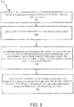
- FIG. 3 is a diagram illustrating a process flow 300 for emergency braking monitoring system 200 in accordance with various embodiments. Occasional reference may also be made to components shown in FIG. 1 and/or FIG. 2 .
- a persistence time and a predetermined time or threshold value is retrieved from a memory location (e.g., look-up table, database, or flat-file) by the emergency braking monitoring unit 234.
- the speed of first wheel 261, second wheel 262, third wheel 263, and/or fourth wheel 264 is ascertained by the emergency braking monitoring unit 234.
- a reference value (as described previously) is ascertained by emergency braking monitoring unit 234.
- emergency braking monitoring unit 234 determines if at least one of the wheel speed values is a predetermined amount less than the reference value for a persistence time.
- step 320 if at least one of ascertained wheel speed values is a predetermined amount less than the reference value for a persistence time, a fault annunciation signal is provided to locked wheel annunciation center 246.
- step 325 a fault annunciation is annunciated to, for example, a pilot, using locked wheel annunciation center 246.
- FIG. 4 is a diagram illustrating a process flow 400 for emergency braking monitoring system 200 in accordance with various embodiments. Occasional reference may also be made to components shown in FIG. 1 and/or FIG. 2 .
- step 405 the speed of first wheel 261 and a reference value is ascertained by emergency braking monitoring unit 234.
- emergency braking monitoring unit 234 determines a speed differential by determining the speed difference of first wheel 261 and the reference value.
- emergency braking monitoring unit 234 determines if the speed differential exceeds a threshold value or predetermined amount.
- emergency braking monitoring unit 234 determines the duration of time corresponding to the speed differential.
- step 425 if the duration of time corresponding to the speed differential is equal to or exceeds a persistence time, a fault annunciation signal 225 is provided to locked wheel annunciation center 246.
- locked wheel annunciation center 246 annunciates the persistence time, threshold value, and/or a notice that a skid is likely to occur, during, for example, a manual emergency braking event.
- FIG. 5 is a diagram illustrating a process flow 500 for emergency braking monitoring system 200 in accordance with various embodiments. Occasional reference may also be made to components shown in FIG. 1 and/or FIG. 2 .
- emergency braking monitoring unit 234 may receive a braking information signal 271 from brake control unit 254.
- step 505 a persistence time and a speed differential corresponding to a first wheel 261 and a reference value is ascertained by the emergency braking monitoring unit 234.
- emergency braking monitoring unit 234 may determine if the amount of braking applied for the speed differential and/or persistence time exceeds a brake threshold likely to blowout first wheel 261, second wheel 262, third wheel 263, and/or fourth wheel 264.
- locked wheel annunciation center 246 annunciates a notification to reduce the amount of emergency braking applied to eliminate or reduce the potential to blowout to first wheel 261, second wheel 262, third wheel 263, and/or fourth wheel 264.
- the annunciation provides feedback via locked wheel annunciation center 246 that allows a determination to be made as to whether an amount of braking requested by, for example, a pilot, is excessive.
- references to “one embodiment”, “an embodiment”, “various embodiments”, etc. indicate that the embodiment described may include a particular feature, structure, or characteristic, but every embodiment may not necessarily include the particular feature, structure, or characteristic. Moreover, such phrases are not necessarily referring to the same embodiment. Further, when a particular feature, structure, or characteristic is described in connection with an embodiment, it is submitted that it is within the knowledge of one skilled in the art to affect such feature, structure, or characteristic in connection with other embodiments whether or not explicitly described. After reading the description, it will be apparent to one skilled in the relevant art(s) how to implement the disclosure in alternative embodiments.
Landscapes
- Engineering & Computer Science (AREA)
- Transportation (AREA)
- Mechanical Engineering (AREA)
- Aviation & Aerospace Engineering (AREA)
- Regulating Braking Force (AREA)
Abstract
Description
- The present disclosure relates to aircraft emergency braking monitoring systems. In particular, the disclosure relates to systems and methods for locked wheel annunciation during emergency braking.
- During normal, non-emergency braking conditions of an aircraft, a typical function of the brake control system is to monitor the wheels of the aircraft for a locked condition. The locked condition may be determined by assessing whether there has been a reduction in rotational wheel speed on any particular wheel as compared to any of the other wheels or combination thereof on the aircraft. The mitigation for this condition provided by the brake control system may be described as locked wheel protection. The locked wheel condition may be provided as a fault message as part of the aircraft diagnostic capabilities. In an emergency braking situation, however, the conditions used to enable locked wheel protection for normal braking situations may not be met or desirable.
- In various embodiments, an emergency braking monitoring system includes a wheel assembly having a first wheel, an emergency braking monitoring unit coupled to the wheel assembly, and a locked wheel annunciation center coupled to the emergency braking monitoring unit for annunciation purposes, wherein the emergency braking monitoring unit generates a fault annunciation signal based on a determination as to whether a first wheel speed value originating from the first wheel of the wheel assembly is a predetermined amount less than a reference value for a persistence time.
- In various embodiments of the emergency braking monitoring system, the reference value is at least one of a second wheel speed value, a third wheel speed value, a fourth wheel speed value, and an aircraft speed.
- In various embodiments of the emergency braking monitoring system, the persistence time is a duration of time for which a fault occurs.
- In various embodiments of the emergency braking monitoring system, the fault annunciation signal is provided to the locked wheel annunciation center coupled to the emergency braking monitoring unit.
- In various embodiments of the emergency braking monitoring system, the locked wheel annunciation center makes an annunciation based on the fault annunciation signal.
- In various embodiments of the emergency braking monitoring system, the annunciation includes at least one of a notice that a skid is likely to occur, , a locked-wheel is likely to occur, a tire blowout is likely to occur, the predetermined amount, and the persistence time.
- In various embodiments of the emergency braking monitoring system, the annunciation occurs during a manual emergency braking event.
- In various embodiments of the emergency braking monitoring system, at least one of the persistence time and the predetermined amount is retrieved from at least one of a lookup-table, database, and flat-file.
- In various embodiments of the emergency braking monitoring system, the wheel assembly includes a first wheel speed monitor coupled to the first wheel to ascertain the first wheel speed value.
- In various embodiments of the emergency braking monitoring system, the wheel assembly includes a second wheel speed monitor coupled to a second wheel to ascertain the second wheel speed value, a third wheel speed monitor coupled to a third wheel to ascertain the third wheel speed value, and a fourth wheel speed monitor coupled to a fourth wheel to ascertain the fourth wheel speed value.
- In various embodiments, an emergency braking monitoring system includes a first wheel speed monitor coupled to a first wheel to ascertain a first wheel speed value, a second wheel speed monitor coupled to a second wheel to ascertain a second wheel speed value, an emergency braking monitoring unit coupled to the first wheel speed monitor and the second wheel speed monitor, wherein the emergency braking monitoring unit makes a determination as to whether a speed differential between the first wheel speed value and the second wheel speed value or an aircraft speed exceeds or is equal to a threshold value for a persistence time and generates an annunciation based on the determination.
- In various embodiments of the emergency braking monitoring system, the persistence time is a duration of time for which a fault occurs.
- In various embodiments of the emergency braking monitoring system, the annunciation is provided by a locked wheel annunciation center.
- In various embodiments of the emergency braking monitoring system, the annunciation includes at least one of a notice that a skid is likely to occur, , a locked-wheel is likely to occur, a tire blowout is likely to occur, the threshold value, and the persistence time.
- In various embodiments of the emergency braking monitoring system, the threshold value is retrieved from at least one of a lookup-table, database, or flat-file.
- In various embodiments of the emergency braking monitoring system, the annunciation occurs during a manual emergency braking.
- In various embodiments, a method of annunciating during an emergency braking includes retrieving, by an emergency braking monitoring unit, a persistence time and a predetermined amount, ascertaining, by the emergency braking monitoring unit, a first wheel speed value of a first wheel using a first wheel speed monitor, ascertaining, by the emergency braking monitoring unit, a reference value that is at least one of a second wheel speed value of a second wheel using a second wheel speed monitor or an aircraft speed, determining, by the emergency braking monitoring unit, whether the first wheel speed value is the predetermined amount less than the reference value for the persistence time, and providing, by the emergency braking monitoring unit, an annunciation based on the determining whether the first wheel speed value is the predetermined amount less than the reference value for the persistence time.
- In various embodiments of the method, the annunciation provides feedback via a locked wheel annunciation center to determine whether an amount of braking requested exceeds a brake threshold.
- In various embodiments of the method, the annunciation provides a notification to reduce the amount of emergency braking applied to at least one of the first wheel, the second wheel, a third wheel, and a fourth wheel.
- In various embodiments of the method, the annunciation includes at least one of a notice that a skid is likely to occur, a notice that a tire blowout is likely to occur, the predetermined amount, and the persistence time.
- The accompanying drawings are included to provide a further understanding of the present disclosure and are incorporated in, and constitute a part of, this specification, illustrate various embodiments, and together with the description, serve to explain the principles of the disclosure.
-
FIG. 1 illustrates a perspective view of a four wheel aircraft configuration in accordance with various embodiments; -
FIG. 2 is a block diagram showing an emergency braking monitoring system in accordance with various embodiments; -
FIG. 3 is a diagram illustrating a process flow for an emergency braking monitoring system in accordance with various embodiments; -
FIG. 4 is a diagram illustrating a process flow for an emergency braking monitoring system in accordance with various embodiments; and -
FIG. 5 is a diagram illustrating a process flow for an emergency braking monitoring system in accordance with various embodiments. - The detailed description of various embodiments herein makes reference to the accompanying drawings, which show various embodiments by way of illustration. While these various embodiments are described in sufficient detail to enable those skilled in the art to practice the disclosure, it should be understood that other embodiments may be realized and that logical, chemical, and mechanical changes may be made without departing from the spirit and scope of the disclosure. Thus, the detailed description herein is presented for purposes of illustration only and not of limitation.
- For example, the steps recited in any of the method or process descriptions may be executed in any order and are not necessarily limited to the order presented. Furthermore, any reference to singular includes plural embodiments, and any reference to more than one component or step may include a singular embodiment or step. Also, any reference to attached, fixed, connected, or the like may include permanent, removable, temporary, partial, full, and/or any other possible attachment option. Additionally, any reference to without contact (or similar phrases) may also include reduced contact or minimal contact.
- For example, in the context of the present disclosure, systems and methods may find particular use in connection with aircraft antiskid braking systems. However, various aspects of the disclosed embodiments may be adapted for optimized performance with a variety of applications implementing brake control systems and/or pressure and/or force controllers. As such, numerous applications of the present disclosure may be realized.
-
FIG. 1 depicts a fourwheel aircraft configuration 100 according to various embodiments. Fourwheel aircraft configuration 100 includes anaircraft 102, afirst wheel 261, asecond wheel 262, athird wheel 263, afourth wheel 264, abrake system 110, and abrake system 111.Brake system 110 is coupled tofirst wheel 261 and asecond wheel 262.Brake system 111 is coupled tothird wheel 263 andfourth wheel 264. Emergency braking monitoring system 200 (referring momentarily toFIG. 2 ) allows an annunciation to be provided to, for example, the pilot ofaircraft 102 and/orbrake control unit 254 to allow the pilot or aircraft to adjust the speed of the wheels to prevent skidding ofaircraft 102. - In various embodiments, during normal operation of
aircraft 102, anti-skid technology may be implemented usingbrake control unit 254 to preventaircraft 102 from skidding. However, during emergency braking ofaircraft 102,brake control unit 254 may be bypassed and fed directly into, for example, a servovalve for hydraulic brakes or an electro-mechanical brake actuator controller (EMAC) for electric brakes.Brake control unit 254 may be bypassed utilizing, for example, an emergency braking handle or an emergency braking button located insideaircraft 102. - As a result of
brake control unit 254 being bypassed during emergency braking, the anti-skid functionality normally provided bybrake control unit 254 may be disabled and/or unable to perform normal anti-skidding operations. Without utilizing emergency braking monitoring unit 234, such an occurrence would likely lead to the pilot ofaircraft 102 not having access to anti-skid functionality and cause an increase in the risk of aircraft skidding and/or rapid tire deflation ("blow out"). Emergency braking monitoring unit 234, however, may be able to perform, for example, anti-skid calculations which may then be provided to pilot ofaircraft 102. -
FIG. 2 depicts an emergencybraking monitoring system 200 according to various embodiments. Emergencybraking monitoring system 200 includes awheel assembly 207, an emergency braking monitoring unit 234, a lockedwheel annunciation center 246, and abrake control unit 254. In various embodiments,wheel assembly 207 is coupled to emergency braking monitoring unit 234, emergency braking monitoring unit 234 is coupled to lockedwheel annunciation center 246 and/orbrake control unit 254, andbrake control unit 254 is coupled towheel assembly 207. Emergency braking monitoring unit 234, lockedwheel annunciation center 246, andbrake control unit 254 may include one or more processors and one or more tangible, non-transitory memories and be capable of storing instructions. The processor/s may be a general purpose processor, a digital signal processor (DSP), an application specific integrated circuit (ASIC), a field programmable gate array (FPGA) or other programmable logic device, discrete gate or transistor logic, discrete hardware components, or any combination thereof. - In various embodiments,
wheel assembly 207 includes a firstwheel speed monitor 213, a secondwheel speed monitor 214, a thirdwheel speed monitor 215, a fourthwheel speed monitor 216, afirst wheel 261, asecond wheel 262, athird wheel 263, and afourth wheel 264. In various embodiments, firstwheel speed monitor 213 may be a speed monitor that monitors the speed of a left outboard wheel (WLOB). Secondwheel speed monitor 214 may be a speed monitor that monitors the speed of a left in board wheel (WLIB). Thirdwheel speed monitor 215 may be a speed monitor that monitors the speed of a right inboard wheel (WRIB). Fourthwheel speed monitor 216 may be a speed monitor that monitors the speed of a right outboard wheel (WROB). Firstwheel speed monitor 213, secondwheel speed monitor 214, thirdwheel speed monitor 215, and fourthwheel speed monitor 216 may be, for example, any type of velocity sensor capable of sensing the angular velocity offirst wheel 261,second wheel 262,third wheel 263, andfourth wheel 264, respectively. - In various embodiments, first
wheel speed monitor 213 is coupled tofirst wheel 261 to ascertain the speed (i.e., first wheel speed value 221) offirst wheel 261. Secondwheel speed monitor 214 is coupled tosecond wheel 262 to ascertain the speed (i.e., second wheel speed value 222) ofsecond wheel 262. Thirdwheel speed monitor 215 is coupled tothird wheel 263 to ascertain the speed (i.e., third wheel speed value 223) ofthird wheel 263. Fourthwheel speed monitor 216 is coupled tofourth wheel 264 to ascertain the speed (i.e., fourth wheel speed value 224) offourth wheel 264. - In various embodiments, during operation of emergency
braking monitoring system 200,wheel assembly 207 provides firstwheel speed value 221, secondwheel speed value 222, thirdwheel speed value 223, and fourthwheel speed value 224 to emergency braking monitoring unit 234. In various embodiments, a monitoring circuit located in, for example, emergency braking monitoring unit 234 receives firstwheel speed value 221, secondwheel speed value 222, thirdwheel speed value 223, and/or fourthwheel speed value 224 fromwheel assembly 207 and determines if a selected at least one of the firstwheel speed value 221, secondwheel speed value 222, thirdwheel speed value 223, and/or fourthwheel speed value 224 is a predetermined amount less than a reference value. The reference value may be defined as, for example, other non-selected wheel speed values and/or the ground speed ofaircraft 102. The reference value may derive from, for example, aircraft avionics. The structure of the monitoring circuit may include, for example, integrated circuit components and the like capable of performing logic and memory operations necessary to perform the operations described herein. - The predetermined amount or threshold value may be defined as a speed difference between a first wheel and a reference value (e.g., second wheel and/or aircraft speed) that is likely to cause
aircraft 102 to skid and may be determined by depending on a variety of factors. The predetermined amount may be, for example, 5 % +- 3%, 10% +- 4%, 15 % +- 5 %, 20% +- 6% of a selected wheel speed value or reference value and may be any other percentage or value determined to be appropriate to reduce and/or prevent skidding or rapid tire deflation ofaircraft 102. In various embodiments, the predetermined amount may be stored in a memory location and may be retrieved from at least one of a lookup-table, database, or flat-file located in, for example, emergency braking monitoring unit 234. - In various embodiments, emergency braking monitoring unit 234 determines whether the threshold value is exceeded for a persistence time. Persistence time may be defined as the time in which a fault occurs. Persistence time may be, for example, the time in which a fault occurs prior to making a fault annunciation and may be determined by designer's preferences. For example, the persistence time may be between 100 milliseconds and 200 milliseconds or any other range of time deemed appropriate to annunciate that skidding of the aircraft may occur. For example, a persistence time may be set for 100 milliseconds. Thus, if an assessment is made by emergency braking monitoring unit 234 that
first wheel 261 is slower than asecond wheel 262 for at least 100 milliseconds, a decision may be made to annunciate that, for example, a skid is likely to occur. In various embodiments, the persistence time may be stored in a memory location and may be retrieved from at least one of a lookup-table, database, or flat-file located in, for example, emergency braking monitoring unit 234. - In various embodiments, when the selected wheel speed value is a predetermined amount less than other non-selected wheel speed values or other reference value for the specified persistence time, a
fault annunciation signal 225 may be provided to lockedwheel annunciation center 246.Fault annunciation signal 225 may, for example, provide lockedwheel annunciation center 246 with the requisite threshold and persistence time. - Locked
wheel annunciation center 246 receives thefault annunciation signal 225 and may annunciate the requisite threshold, the persistence time, and/or a notice that at least one wheel speed is sufficiently distinct from the other wheel speeds, and/or does not meet an expected velocity magnitude. The fault annunciation may occur during manual emergency braking and may provide feedback to, for example, a pilot of aircraft 201 to determine whether the amount of braking requested is excessive. The annunciation may provide the pilot with feedback to decide whether to reduce the amount of emergency braking applied to possibly eliminate or reduce the potential to blowout and/or lockfirst wheel 261,second wheel 262,third wheel 263, and/orfourth wheel 264 due to excessive skidding. For example, lockedwheel annunciation center 246 may annunciate that a skid is likely to occur, a locked-wheel is likely to occur, and/or a tire blowout is likely to occur. In addition, lockedwheel annunciation center 246 may annunciate the predetermined amount and/or persistence time. - In various embodiments, emergency braking monitoring unit 234 may also provide a
brake notification signal 226 containing the requisite threshold and persistence time to brakecontrol unit 254. Thebrake notification signal 226 may allowbrake control unit 254 to provide anadjustment signal 220 towheel assembly 207 to allowwheel assembly 207 to adjust the speed offirst wheel 261,second wheel 262,third wheel 263, furtherfourth wheel 264, accordingly. - In various embodiments, emergency braking monitoring unit 234 may compare first
wheel speed value 221 to secondwheel speed value 222 and determine a first speed differential (i.e., the difference between firstwheel speed value 221 and second wheel speed value 222). Emergency braking monitoring unit 234 may compare the first speed differential to a threshold value and determine whether the first speed differential is greater than, less than, or equal to the threshold value for a persistence time. If the first speed differential is greater than or equal to the threshold value for the persistence time,fault annunciation signal 225 may be provided to lockedwheel annunciation center 246 to annunciate the requisite threshold and persistence time to the pilot ofaircraft 102. - In various embodiments, for example, if the first
wheel speed value 221 is 200 mph (322 kph) and the secondwheel speed value 222 is 212 mph (341 kph), then the first speed differential is 12 mph (19 kph). If the threshold value is 10 mph (16 kpg), then first speed differential exceeds the threshold value by 2 mph (3 kph). If the persistence time is 200 milliseconds and the first speed differential is greater than the threshold value for more than the persistence time of 200 milliseconds, then afault annunciation signal 225 may be sent to lockedwheel annunciation center 246 for annunciation to the pilot. The pilot may then use the annunciation to prevent skidding ofaircraft 102 or to reduce the amount of emergency braking to apply to possibly eliminate or reduce the potential to blowoutfirst wheel 261,second wheel 262,third wheel 263, and/orfourth wheel 264. - In various embodiments, with further reference to
FIG. 2 , emergency braking monitoring unit 234 may receive a braking information signal 271 frombrake control unit 254. Braking information signal 271 may contain, for example, information about the amount of brake applied by the pilot orbrake control unit 254 tofirst wheel 261,second wheel 262,third wheel 263, and/orfourth wheel 264. Emergency braking monitoring unit 234 may determine if the amount of braking applied corresponding to a persistence time and/or a speed differential of afirst wheel 261 and a reference value exceeds a brake threshold likely to blowoutfirst wheel 261,second wheel 262,third wheel 263, and/orfourth wheel 264. The brake threshold may be, for example, any amount of brake pressure deemed appropriate to prevent tire blowout for the prescribed speed differential and/or persistence time. If the brake amount exceeds the brake threshold for the prescribed speed differential and/or persistence time, lockedwheel annunciation center 246 annunciates a notification to reduce the amount of emergency braking applied to eliminate or reduce the potential to blowout and/or lockfirst wheel 261,second wheel 262,third wheel 263, and/orfourth wheel 264. -
FIG. 3 is a diagram illustrating aprocess flow 300 for emergencybraking monitoring system 200 in accordance with various embodiments. Occasional reference may also be made to components shown inFIG. 1 and/orFIG. 2 . Instep 302, a persistence time and a predetermined time or threshold value is retrieved from a memory location (e.g., look-up table, database, or flat-file) by the emergency braking monitoring unit 234. Instep 305, the speed offirst wheel 261,second wheel 262,third wheel 263, and/orfourth wheel 264 is ascertained by the emergency braking monitoring unit 234. Instep 308, a reference value (as described previously) is ascertained by emergency braking monitoring unit 234. Instep 310, emergency braking monitoring unit 234 determines if at least one of the wheel speed values is a predetermined amount less than the reference value for a persistence time. Instep 320, if at least one of ascertained wheel speed values is a predetermined amount less than the reference value for a persistence time, a fault annunciation signal is provided to lockedwheel annunciation center 246. Instep 325, a fault annunciation is annunciated to, for example, a pilot, using lockedwheel annunciation center 246. -
FIG. 4 is a diagram illustrating aprocess flow 400 for emergencybraking monitoring system 200 in accordance with various embodiments. Occasional reference may also be made to components shown inFIG. 1 and/orFIG. 2 . Instep 405, the speed offirst wheel 261 and a reference value is ascertained by emergency braking monitoring unit 234. Instep 410, emergency braking monitoring unit 234 determines a speed differential by determining the speed difference offirst wheel 261 and the reference value. Instep 415, emergency braking monitoring unit 234 determines if the speed differential exceeds a threshold value or predetermined amount. Instep 420, if the speed differential exceeds or is equal to the threshold value, emergency braking monitoring unit 234 determines the duration of time corresponding to the speed differential. Instep 425, if the duration of time corresponding to the speed differential is equal to or exceeds a persistence time, afault annunciation signal 225 is provided to lockedwheel annunciation center 246. Instep 430, lockedwheel annunciation center 246 annunciates the persistence time, threshold value, and/or a notice that a skid is likely to occur, during, for example, a manual emergency braking event. -
FIG. 5 is a diagram illustrating aprocess flow 500 for emergencybraking monitoring system 200 in accordance with various embodiments. Occasional reference may also be made to components shown inFIG. 1 and/orFIG. 2 . In various embodiments, instep 502, emergency braking monitoring unit 234 may receive a braking information signal 271 frombrake control unit 254. Instep 505, a persistence time and a speed differential corresponding to afirst wheel 261 and a reference value is ascertained by the emergency braking monitoring unit 234. Instep 508, emergency braking monitoring unit 234 may determine if the amount of braking applied for the speed differential and/or persistence time exceeds a brake threshold likely to blowoutfirst wheel 261,second wheel 262,third wheel 263, and/orfourth wheel 264. In step 510, if the brake amount exceeds the brake threshold for the speed differential and/or persistence time, lockedwheel annunciation center 246 annunciates a notification to reduce the amount of emergency braking applied to eliminate or reduce the potential to blowout tofirst wheel 261,second wheel 262,third wheel 263, and/orfourth wheel 264. In various embodiments, the annunciation provides feedback via lockedwheel annunciation center 246 that allows a determination to be made as to whether an amount of braking requested by, for example, a pilot, is excessive. - Those of ordinary skill in the art will appreciate that these components and others, are presented herein for explanation. Variations may be made among the components, configurations, and linkages without departing from the scope of this disclosure. Along similar lines, the systems and methods described herein may be applied to any suitable number of wheels (e.g., one or more wheels) and/or any vehicle having wheels.
- Benefits, other advantages, and solutions to problems have been described herein with regard to specific embodiments. Furthermore, the connecting lines shown in the various figures contained herein are intended to represent exemplary functional relationships and/or physical couplings between the various elements. It should be noted that many alternative or additional functional relationships or physical connections may be present in a practical system. However, the benefits, advantages, solutions to problems, and any elements that may cause any benefit, advantage, or solution to occur or become more pronounced are not to be construed as critical, required, or essential features or elements of the disclosure. The scope of the disclosure is accordingly to be limited by nothing other than the appended claims, in which reference to an element in the singular is not intended to mean "one and only one" unless explicitly so stated, but rather "one or more." Moreover, where a phrase similar to "at least one of A, B, or C" is used in the claims, it is intended that the phrase be interpreted to mean that A alone may be present in an embodiment, B alone may be present in an embodiment, C alone may be present in an embodiment, or that any combination of the elements A, B and C may be present in a single embodiment; for example, A and B, A and C, B and C, or A and B and C.
- Devices and methods are provided herein. In the detailed description herein, references to "one embodiment", "an embodiment", "various embodiments", etc., indicate that the embodiment described may include a particular feature, structure, or characteristic, but every embodiment may not necessarily include the particular feature, structure, or characteristic. Moreover, such phrases are not necessarily referring to the same embodiment. Further, when a particular feature, structure, or characteristic is described in connection with an embodiment, it is submitted that it is within the knowledge of one skilled in the art to affect such feature, structure, or characteristic in connection with other embodiments whether or not explicitly described. After reading the description, it will be apparent to one skilled in the relevant art(s) how to implement the disclosure in alternative embodiments.
- Furthermore, no element, component, or method step in the present disclosure is intended to be dedicated to the public regardless of whether the element, component, or method step is explicitly recited in the claims. As used herein, the terms "comprises", "comprising", or any other variation thereof, are intended to cover a non-exclusive inclusion, such that a process, method, article, or apparatus that comprises a list of elements does not include only those elements but may include other elements not expressly listed or inherent to such process, method, article, or apparatus.
Claims (15)
- An emergency braking monitoring system, comprising:a wheel assembly (207) having a first wheel (261);an emergency braking monitoring unit (234) coupled to said wheel assembly (207); anda locked wheel annunciation center (246) coupled to said emergency braking monitoring unit (234) for annunciation purposes, wherein said emergency braking monitoring unit (234) generates a fault annunciation signal based on a determination as to whether a first wheel speed value (221) originating from said first wheel (261) of said wheel assembly is a predetermined amount less than a reference value for a persistence time.
- The emergency braking monitoring system of claim 1, wherein said reference value is at least one of a second wheel speed value (222), a third wheel speed value (223), a fourth wheel speed value (224), and an aircraft speed.
- The emergency braking monitoring system of claim 1 or 2, wherein said persistence time is a duration of time for which a fault occurs.
- The emergency braking monitoring system of claim 1, 2 or 3, wherein said fault annunciation signal is provided to said locked wheel annunciation center (246) coupled to said emergency braking monitoring unit (234).
- The emergency braking monitoring system of claim 4, wherein said locked wheel annunciation center (246) makes an annunciation based on said fault annunciation signal.
- The emergency braking monitoring system of claim 5, wherein said annunciation includes at least one of a notice that a skid is likely to occur, a locked-wheel is likely to occur, a tire blowout is likely to occur, said predetermined amount, and said persistence time, or wherein said annunciation occurs during a manual emergency braking event.
- The emergency braking monitoring system of any preceding claim, wherein at least one of said persistence time and said predetermined amount is retrieved from at least one of a lookup-table, database, and flat-file.
- The emergency braking monitoring system of claim 2, wherein said wheel assembly (207) includes a first wheel speed monitor coupled to said first wheel to ascertain said first wheel speed value, and preferably wherein said wheel assembly (207) includes a second wheel speed monitor coupled to a second wheel (262) to ascertain said second wheel speed value (222), a third wheel speed monitor coupled to a third wheel (263) to ascertain said third wheel speed value (223), and a fourth wheel speed monitor coupled to a fourth wheel (264) to ascertain said fourth wheel speed value (224).
- An emergency braking monitoring system, comprising:a first wheel speed monitor coupled to a first wheel (261) to ascertain a first wheel speed value (221);a second wheel speed monitor coupled to a second wheel (262) to ascertain a second wheel speed value (222);an emergency braking monitoring unit (234) coupled to said first wheel speed monitor and said second wheel speed monitor, wherein said emergency braking monitoring unit (234) makes a determination as to whether a speed differential between said first wheel speed value (221) and said second wheel speed value (222) or an aircraft speed exceeds or is equal to a threshold value for a persistence time and generates an annunciation based on said determination.
- The emergency braking monitoring system of claim 9, wherein said persistence time is a duration of time for which a fault occurs.
- The emergency braking monitoring system of claim 9 or 10, wherein said annunciation is provided by a locked wheel annunciation center.
- The emergency braking monitoring system of claim 9, 10 or 11, wherein said annunciation includes at least one of a notice that a skid is likely to occur, a locked-wheel is likely to occur, a tire blowout is likely to occur, said threshold value, and said persistence time, or wherein said threshold value is retrieved from at least one of a lookup-table, database, or flat-file, or wherein said annunciation occurs during a manual emergency braking.
- A method of annunciating during an emergency braking, comprising:retrieving, by an emergency braking monitoring unit (234), a persistence time and a predetermined amount;ascertaining, by said emergency braking monitoring unit, a first wheel speed value (221) of a first wheel (261) using a first wheel speed monitor;ascertaining, by said emergency braking monitoring unit (234), a reference value that is at least one of a second wheel speed value (222) of a second wheel (262) using a second wheel speed monitor or an aircraft speed;determining, by said emergency braking monitoring unit (234), whether said first wheel speed value (221) is said predetermined amount less than said reference value for said persistence time; andproviding, by said emergency braking monitoring unit (234), an annunciation based on said determining whether said first wheel speed value (221) is said predetermined amount less than said reference value for said persistence time.
- The method of claim 13, wherein said annunciation provides feedback via a locked wheel annunciation center to determine whether an amount of braking requested exceeds a brake threshold, and preferably wherein said annunciation provides a notification to reduce an amount of emergency braking applied to at least one of said first wheel (261), said second wheel (262), a third wheel (263), and a fourth wheel (264).
- The method of claim 13 or 14, wherein said annunciation includes at least one of a notice that a skid is likely to occur, a notice that a tire blowout is likely to occur, said predetermined amount, and said persistence time.
Applications Claiming Priority (1)
| Application Number | Priority Date | Filing Date | Title |
|---|---|---|---|
| US15/730,584 US10358121B2 (en) | 2017-10-11 | 2017-10-11 | Locked wheel annunciation during emergency braking |
Publications (1)
| Publication Number | Publication Date |
|---|---|
| EP3470281A1 true EP3470281A1 (en) | 2019-04-17 |
Family
ID=64051294
Family Applications (1)
| Application Number | Title | Priority Date | Filing Date |
|---|---|---|---|
| EP18199713.1A Withdrawn EP3470281A1 (en) | 2017-10-11 | 2018-10-10 | Locked wheel annunciation during emergency braking |
Country Status (2)
| Country | Link |
|---|---|
| US (1) | US10358121B2 (en) |
| EP (1) | EP3470281A1 (en) |
Families Citing this family (1)
| Publication number | Priority date | Publication date | Assignee | Title |
|---|---|---|---|---|
| GB2604604A (en) * | 2021-03-08 | 2022-09-14 | Airbus Operations Ltd | An aircraft brake control system |
Citations (6)
| Publication number | Priority date | Publication date | Assignee | Title |
|---|---|---|---|---|
| US3847445A (en) * | 1973-11-12 | 1974-11-12 | Boeing Co | Aircraft automatic braking system having auto-brake control logic |
| US3880475A (en) * | 1972-03-29 | 1975-04-29 | Goodyear Tire & Rubber | Anti-skid system |
| US4006941A (en) * | 1974-12-20 | 1977-02-08 | The Boeing Company | Aircraft brake control system having hydroplaning protection |
| DE2739468A1 (en) * | 1976-09-03 | 1978-03-09 | Dunlop Ltd | ANTI-LOCK BRAKE SYSTEM FOR A VEHICLE WHEEL BRAKE |
| US4115756A (en) * | 1976-09-27 | 1978-09-19 | Avmar, Incorporated | Wheel and brake advisory system for aircraft |
| WO2000023305A1 (en) * | 1998-10-19 | 2000-04-27 | Alliedsignal Inc. | Method and apparatus for monitoring brake operation in an anti-lock or electronic braking system |
Family Cites Families (14)
| Publication number | Priority date | Publication date | Assignee | Title |
|---|---|---|---|---|
| US3525553A (en) * | 1968-09-30 | 1970-08-25 | Bendix Corp | Adaptive braking system responsive to tire-road surface conditions |
| US3614173A (en) * | 1969-06-27 | 1971-10-19 | Bendix Corp | Slip command skid control |
| US3702714A (en) * | 1971-04-30 | 1972-11-14 | Bendix Corp | Slip command skid control with acceleration override |
| JP3428216B2 (en) * | 1995-03-16 | 2003-07-22 | 日産自動車株式会社 | Operating state detection device for freewheel hub mechanism |
| US5896083A (en) * | 1997-05-16 | 1999-04-20 | Detroit Diesel Corporation | System and method for detecting vehicle speed sensor tampering |
| US6711488B2 (en) * | 2002-05-22 | 2004-03-23 | Goodrich Corporation | Wheel deceleration-based antiskid brake controller with adaptive deceleration threshold |
| US6882920B2 (en) * | 2003-04-29 | 2005-04-19 | Goodrich Corporation | Brake control system |
| US9227608B2 (en) * | 2009-08-12 | 2016-01-05 | Meggitt Aircraft Braking Systems | Decentralized electric brake system |
| US9981754B2 (en) * | 2015-11-13 | 2018-05-29 | Goodrich Corporation | System and method for detecting bad runway conditions |
| JP6609498B2 (en) * | 2016-03-28 | 2019-11-20 | 株式会社ショーワ | Vehicle height adjustment device |
| JP6622129B2 (en) * | 2016-03-28 | 2019-12-18 | 株式会社ショーワ | Vehicle height adjustment device |
| CN106004833A (en) | 2016-05-31 | 2016-10-12 | 中国航空工业集团公司西安飞机设计研究所 | Aircraft antiskid braking control system |
| CN106394880B (en) | 2016-10-18 | 2018-12-11 | 西安航空制动科技有限公司 | A kind of aircraft electronic anti-skid brake system (ABS) ensuring emergency brake operation |
| CN106394881B (en) | 2016-10-18 | 2018-08-07 | 西安航空制动科技有限公司 | A kind of power-on self-test protection method of aircraft anti-skid brake system |
-
2017
- 2017-10-11 US US15/730,584 patent/US10358121B2/en not_active Expired - Fee Related
-
2018
- 2018-10-10 EP EP18199713.1A patent/EP3470281A1/en not_active Withdrawn
Patent Citations (6)
| Publication number | Priority date | Publication date | Assignee | Title |
|---|---|---|---|---|
| US3880475A (en) * | 1972-03-29 | 1975-04-29 | Goodyear Tire & Rubber | Anti-skid system |
| US3847445A (en) * | 1973-11-12 | 1974-11-12 | Boeing Co | Aircraft automatic braking system having auto-brake control logic |
| US4006941A (en) * | 1974-12-20 | 1977-02-08 | The Boeing Company | Aircraft brake control system having hydroplaning protection |
| DE2739468A1 (en) * | 1976-09-03 | 1978-03-09 | Dunlop Ltd | ANTI-LOCK BRAKE SYSTEM FOR A VEHICLE WHEEL BRAKE |
| US4115756A (en) * | 1976-09-27 | 1978-09-19 | Avmar, Incorporated | Wheel and brake advisory system for aircraft |
| WO2000023305A1 (en) * | 1998-10-19 | 2000-04-27 | Alliedsignal Inc. | Method and apparatus for monitoring brake operation in an anti-lock or electronic braking system |
Also Published As
| Publication number | Publication date |
|---|---|
| US20190106092A1 (en) | 2019-04-11 |
| US10358121B2 (en) | 2019-07-23 |
Similar Documents
| Publication | Publication Date | Title |
|---|---|---|
| US10220824B2 (en) | Electronic brake support system for use when service brake system has failed or is degraded | |
| KR101957874B1 (en) | A vehicle braking arrangement | |
| EP4180287B1 (en) | Systems and methods for brake health monitoring | |
| US8874310B2 (en) | Method for securing an electrically operated parking brake | |
| EP3184382B1 (en) | Locked wheel extension protection in brake control systems | |
| EP3187386B1 (en) | Anti-skid protection with undetected pressure sensor failure | |
| JP2017516706A (en) | Vehicle occupant protection method and vehicle occupant protection device | |
| EP3712021B1 (en) | Systems and methods for antiskid tolerant multi-mode autobrake control | |
| EP3269604A1 (en) | Antiskid brake control system with minimum disruption autobrake function | |
| US20140032076A1 (en) | Method of maintaining optimal braking and skid protection for a two-wheeled vehicle having a speed sensor failure on a single wheel | |
| US11097699B2 (en) | Method for activating a parking brake of a motor vehicle, and system for controlling a parking brake of a motor vehicle | |
| US5764137A (en) | System and method for diagnosing loss of pressure in tires of a vehicle | |
| US10300901B2 (en) | Validation of brake torque signal for use as a brake event | |
| US10358121B2 (en) | Locked wheel annunciation during emergency braking | |
| KR102895292B1 (en) | Method for controlling dynamic braking for electronic parking brake | |
| EP3964409A1 (en) | Systems and methods for low speed braking operation | |
| EP3246210B1 (en) | System and method for activation of warning lights of a vehicle | |
| US9187070B2 (en) | System and method for maintaining operational states of vehicle remote actuators during failure conditions | |
| US12351148B2 (en) | Method for securing a vehicle | |
| US8036794B2 (en) | Method and device for preventively actuating a vehicle occupant protection system | |
| EP4360970B1 (en) | Advanced locked wheel protection functionality | |
| EP4559783A1 (en) | Method to control safe levels of assistance torque in a steering system with closed loop control | |
| CN118387039A (en) | Vehicle airbag braking method, system, equipment and storage medium | |
| US11035895B2 (en) | Signal acquisition apparatus and a method for controlling the signal acquisition apparatus | |
| JPH06343289A (en) | Detector for abnormality of motor |
Legal Events
| Date | Code | Title | Description |
|---|---|---|---|
| PUAI | Public reference made under article 153(3) epc to a published international application that has entered the european phase |
Free format text: ORIGINAL CODE: 0009012 |
|
| STAA | Information on the status of an ep patent application or granted ep patent |
Free format text: STATUS: THE APPLICATION HAS BEEN PUBLISHED |
|
| AK | Designated contracting states |
Kind code of ref document: A1 Designated state(s): AL AT BE BG CH CY CZ DE DK EE ES FI FR GB GR HR HU IE IS IT LI LT LU LV MC MK MT NL NO PL PT RO RS SE SI SK SM TR |
|
| AX | Request for extension of the european patent |
Extension state: BA ME |
|
| STAA | Information on the status of an ep patent application or granted ep patent |
Free format text: STATUS: REQUEST FOR EXAMINATION WAS MADE |
|
| 17P | Request for examination filed |
Effective date: 20191017 |
|
| RBV | Designated contracting states (corrected) |
Designated state(s): AL AT BE BG CH CY CZ DE DK EE ES FI FR GB GR HR HU IE IS IT LI LT LU LV MC MK MT NL NO PL PT RO RS SE SI SK SM TR |
|
| GRAP | Despatch of communication of intention to grant a patent |
Free format text: ORIGINAL CODE: EPIDOSNIGR1 |
|
| STAA | Information on the status of an ep patent application or granted ep patent |
Free format text: STATUS: GRANT OF PATENT IS INTENDED |
|
| RIC1 | Information provided on ipc code assigned before grant |
Ipc: B60T 8/17 20060101AFI20210614BHEP |
|
| INTG | Intention to grant announced |
Effective date: 20210720 |
|
| STAA | Information on the status of an ep patent application or granted ep patent |
Free format text: STATUS: THE APPLICATION IS DEEMED TO BE WITHDRAWN |
|
| 18D | Application deemed to be withdrawn |
Effective date: 20211201 |