EP3470245B1 - Tire pressure detector with wheel balancing function and wheel balancing system thereof - Google Patents
Tire pressure detector with wheel balancing function and wheel balancing system thereof Download PDFInfo
- Publication number
- EP3470245B1 EP3470245B1 EP18156008.7A EP18156008A EP3470245B1 EP 3470245 B1 EP3470245 B1 EP 3470245B1 EP 18156008 A EP18156008 A EP 18156008A EP 3470245 B1 EP3470245 B1 EP 3470245B1
- Authority
- EP
- European Patent Office
- Prior art keywords
- tire
- pressure
- tire pressure
- pressure detector
- wheel
- Prior art date
- Legal status (The legal status is an assumption and is not a legal conclusion. Google has not performed a legal analysis and makes no representation as to the accuracy of the status listed.)
- Active
Links
Images



Classifications
-
- B—PERFORMING OPERATIONS; TRANSPORTING
- B60—VEHICLES IN GENERAL
- B60C—VEHICLE TYRES; TYRE INFLATION; TYRE CHANGING; CONNECTING VALVES TO INFLATABLE ELASTIC BODIES IN GENERAL; DEVICES OR ARRANGEMENTS RELATED TO TYRES
- B60C19/00—Tyre parts or constructions not otherwise provided for
- B60C19/003—Balancing means attached to the tyre
-
- B—PERFORMING OPERATIONS; TRANSPORTING
- B60—VEHICLES IN GENERAL
- B60C—VEHICLE TYRES; TYRE INFLATION; TYRE CHANGING; CONNECTING VALVES TO INFLATABLE ELASTIC BODIES IN GENERAL; DEVICES OR ARRANGEMENTS RELATED TO TYRES
- B60C23/00—Devices for measuring, signalling, controlling, or distributing tyre pressure or temperature, specially adapted for mounting on vehicles; Arrangement of tyre inflating devices on vehicles, e.g. of pumps or of tanks; Tyre cooling arrangements
- B60C23/02—Signalling devices actuated by tyre pressure
- B60C23/04—Signalling devices actuated by tyre pressure mounted on the wheel or tyre
-
- B—PERFORMING OPERATIONS; TRANSPORTING
- B60—VEHICLES IN GENERAL
- B60C—VEHICLE TYRES; TYRE INFLATION; TYRE CHANGING; CONNECTING VALVES TO INFLATABLE ELASTIC BODIES IN GENERAL; DEVICES OR ARRANGEMENTS RELATED TO TYRES
- B60C23/00—Devices for measuring, signalling, controlling, or distributing tyre pressure or temperature, specially adapted for mounting on vehicles; Arrangement of tyre inflating devices on vehicles, e.g. of pumps or of tanks; Tyre cooling arrangements
- B60C23/02—Signalling devices actuated by tyre pressure
- B60C23/04—Signalling devices actuated by tyre pressure mounted on the wheel or tyre
- B60C23/0408—Signalling devices actuated by tyre pressure mounted on the wheel or tyre transmitting the signals by non-mechanical means from the wheel or tyre to a vehicle body mounted receiver
-
- B—PERFORMING OPERATIONS; TRANSPORTING
- B60—VEHICLES IN GENERAL
- B60C—VEHICLE TYRES; TYRE INFLATION; TYRE CHANGING; CONNECTING VALVES TO INFLATABLE ELASTIC BODIES IN GENERAL; DEVICES OR ARRANGEMENTS RELATED TO TYRES
- B60C23/00—Devices for measuring, signalling, controlling, or distributing tyre pressure or temperature, specially adapted for mounting on vehicles; Arrangement of tyre inflating devices on vehicles, e.g. of pumps or of tanks; Tyre cooling arrangements
- B60C23/02—Signalling devices actuated by tyre pressure
- B60C23/04—Signalling devices actuated by tyre pressure mounted on the wheel or tyre
- B60C23/0408—Signalling devices actuated by tyre pressure mounted on the wheel or tyre transmitting the signals by non-mechanical means from the wheel or tyre to a vehicle body mounted receiver
- B60C23/0422—Signalling devices actuated by tyre pressure mounted on the wheel or tyre transmitting the signals by non-mechanical means from the wheel or tyre to a vehicle body mounted receiver characterised by the type of signal transmission means
- B60C23/0433—Radio signals
- B60C23/0447—Wheel or tyre mounted circuits
-
- B—PERFORMING OPERATIONS; TRANSPORTING
- B60—VEHICLES IN GENERAL
- B60C—VEHICLE TYRES; TYRE INFLATION; TYRE CHANGING; CONNECTING VALVES TO INFLATABLE ELASTIC BODIES IN GENERAL; DEVICES OR ARRANGEMENTS RELATED TO TYRES
- B60C23/00—Devices for measuring, signalling, controlling, or distributing tyre pressure or temperature, specially adapted for mounting on vehicles; Arrangement of tyre inflating devices on vehicles, e.g. of pumps or of tanks; Tyre cooling arrangements
- B60C23/02—Signalling devices actuated by tyre pressure
- B60C23/04—Signalling devices actuated by tyre pressure mounted on the wheel or tyre
- B60C23/0491—Constructional details of means for attaching the control device
- B60C23/0493—Constructional details of means for attaching the control device for attachment on the tyre
-
- F—MECHANICAL ENGINEERING; LIGHTING; HEATING; WEAPONS; BLASTING
- F16—ENGINEERING ELEMENTS AND UNITS; GENERAL MEASURES FOR PRODUCING AND MAINTAINING EFFECTIVE FUNCTIONING OF MACHINES OR INSTALLATIONS; THERMAL INSULATION IN GENERAL
- F16F—SPRINGS; SHOCK-ABSORBERS; MEANS FOR DAMPING VIBRATION
- F16F15/00—Suppression of vibrations in systems; Means or arrangements for avoiding or reducing out-of-balance forces, e.g. due to motion
- F16F15/32—Correcting- or balancing-weights or equivalent means for balancing rotating bodies, e.g. vehicle wheels
- F16F15/36—Correcting- or balancing-weights or equivalent means for balancing rotating bodies, e.g. vehicle wheels operating automatically, i.e. where, for a given amount of imbalance, there is movement of masses until balance is achieved
- F16F15/363—Correcting- or balancing-weights or equivalent means for balancing rotating bodies, e.g. vehicle wheels operating automatically, i.e. where, for a given amount of imbalance, there is movement of masses until balance is achieved using rolling bodies, e.g. balls free to move in a circumferential direction
Definitions
- the present invention relates to tire pressure detection, and more particularly, to a tire pressure detector with wheel balancing function and wheel balancing system thereof.
- a tire detection system is an electronic system disposed at a vehicle wheel for detecting the sufficiency of pressure of the tire, whereby the variation of tire pressure is immediately monitored and displayed through a panel board, a digital displayer, or simple light signals, so as to prevent traffic accidents from occurring due to overpressure of the tire.
- the operation method of a tire detection system mainly comprises a direct type and an indirect type detection system.
- the indirect type tire pressure detection system instead of directly detecting the tire pressure of a wheel, detects the rotation speed of the wheel. If the system detects the rotation speed of a certain wheel differs from the rotation speed of other wheels in a large degree, the tire pressure of the certain wheel might possibly be abnormal. Therefore, the system informs the driver of the abnormality.
- the indirect tire pressure detection system fails to provide an actual tire pressure value to the driver.
- a non-attached tire monitoring device disclosed in US 2004/154388 includes a monitoring assembly and an antenna.
- the antenna is configured to successfully radiate a substantial portion of the radio signal through the oriented attenuating body of the tire sidewall regardless of the position of the monitoring device with respect to the tire sidewall. As a result, constant performance independent of the position of the monitoring device is provided.
- Non-attached monitoring device including a body with a monitoring assembly carried by the central portion.
- a plurality of spaced fingers projecting from the central portion of the body are adapted to support the monitoring assembly in a spaced located from the inner surface of the tire, and cushion the monitoring assembly and raise it above any liquid that may be disposed in the tire.
- EP1000776 reveals a non-attached monitoring assembly for pneumatic tire, including an electronic monitoring device having at least one sensor disposed in a protective body.
- the protective body includes an encapsulation layer that encapsulates the substrate and sensors, a cushion, and a skin on the outside of the cushion.
- the protective body is substantially spherical allowing the assembly to roll about the inside of a tire without being permanently connected to the tire.
- a breathing tube through the protective body is provided so that a pressure sensor is allowed to sense the pressure within the pneumatic tire.
- the breathing tube may be filled with a transfer gel to prevent the breathing tube from being clogged.
- JP2006168478 is referring to a tire particle aggregate, which is the aggregate of the tire having at least a side wall part and a plurality of hollow particles filled with a high pressure gas exceeding an atmosphere pressure in a tire's air space partitioned by the tire and a rim.
- the tire particle aggregate suppresses the occurrence of burst by improving durability against wear of a buttress part and can obtain a stable traveling even after being punctured.
- FR2083601 discloses an automatic wheel balancing device, which comprises an annular tube of rectangular cross-section, extruded into a predetermined shape corresponding to the interior profile of the vehicle wheel rim, and further comprises a plurality of movable weights in the shape of cylindrical discs or rollers having somewhat reduced cross-sectional dimension in relation to the interior cross-section of the tube so as to roll freely therearound, and a certain predetermined quantity of damping liquid such as oil or the like to damp the movement of the weights.
- a greatly increased movable mass is incorporated within the tube, and the tube is substantially free of any distortion in use, thereby eliminating whipping or chatter of the tube, and also the wear on the interior of the tube.
- the direct type tire pressure detection system is provided with a detection device capable of transmitting signals, which provides an actual tire pressure value of the wheel to the driver.
- the detection devices are further categorized into the internal type and the external type.
- the external type detection device is disposed at the air tap of the wheel and allowed to be manually installed.
- the detection device possesses a certain weight.
- the detection device When being fastened on the air tap, the detection device causes the mass of the wheel to be unevenly distributed, so as to affect the balance of the wheel. Also, the detection device shall be disassembled during the air filling process of the wheel, thus imposing a risk of damaging the detection device.
- the air tap made of rubber material when the air tap made of rubber material is combined with the external type detection device, the air tap might waves during the movement of the vehicle. After a long duration, the rubber body of the air tap may possibly be broken.
- the internal type detection device is disposed in the rim of the wheel. Therefore, the internal type detection device usually has to be installed by a vehicle maintenance work, and the wheel shall be rebalanced after the installation of the internal type detection device.
- a tire pressure detector is disclosed.
- the main body provided with the detection module disposed in the pressure space, the main body is allowed to move inside the tire during the movement of the vehicle, so as to balance the mass of the wheel, reduce the vibration thereof, and detect the air pressure in the pressure space through the detection module, thus achieving the wheel balancing and tire pressure detection functions.
- a tire pressure detector with wheel balancing function in accordance with an embodiment of the present invention is provided, wherein the wheel includes a rim and a tire mounted around the rim, such that a pressure space is produced between the tire and the rim, and the rim is provided with an air tap connected with the pressure space.
- the tire pressure detector comprises:
- the main body provided with the detection module is placed in the pressure space, such that the main body moves inside the tire during the movement of the wheel for detecting the pressure in the pressure space. Therefore, the detector does not need to be fixed on the tire, which may cause the unevenness of the wheel mass, and the wheel rebalancing process after the installation is omitted, saving a rather complicated installation procedure. Thus, the installation easiness and convenience of usage are facilitated.
- the present invention achieves both the wheel balancing and tire pressure detection function.
- the tire pressure detector in accordance with the present invention is simply placed in the pressure space between the tire and the rim for balancing the wheel and detecting the tire pressure, without the necessity of being disposed according to the specification of the wheel or the position of the air tap. Therefore, the present invention is applicable to various wheels, enhancing the scope of usage of the present invention.
- a wheel balancing system applying the tire pressure detector in accordance with another embodiment of the present invention comprises a plurality of balancing members that are movably disposed in the pressure space together with the tire pressure detector. Therefore, the waving issue of the wheel is reduced to improve the balance of the wheel, such that the driving safety is enhanced.
- a tire pressure detector 100 with wheel balancing function is provided, which is operated at a vehicle wheel, including the wheel of a motorcycle or a car.
- the vehicle refers to a car.
- the wheel 1 comprises a rim 2 and a tire 3 mounted around the rim 2.
- the rim 2 is provided with an outer surface 4 and an outer wall 5.
- the outer surface 4 faces one end of the rotational axis of the wheel, and the outer wall 5 surrounds the rotational axis of the wheel 1.
- the tire 3 comprises an outer tire face 6 and an inner tire face 7, wherein the inner tire face 7 of the tire 3 faces the outer wall 5 of the rim 2 and is mounted around the rim 2, with a pressure space 8 formed between the inner tire face 7 of the tire 3 and the outer wall 5 of the rim 2.
- the outer tire face 6 of the tire 3 contacts the ground.
- the outer surface 4 of the rim 2 is provided with an air tap 9 which is connected with the pressure space 8, wherein the air tap 9 input air into the pressure space 8.
- the tire pressure detector 100 comprises a main body 10 and the detection module 20.
- the detection module 20 is disposed in a housing space 11 inside the main body 10.
- the main body 10 is movably disposed in the pressure space 8 for balancing the mass of the wheel 1 and detecting the air pressure in the pressure space 8 through a sensing unit 21 of the detection module 20. Therefore, the present invention achieves both the tire pressure detection and wheel balancing functions.
- the main body 10 includes an outer edge 12.
- the shape of the main body 10 is allowed to be ball-shaped, an oval-shaped, or a polygonal-shaped. In an embodiment of the present invention, the main body 10 is ball-shaped.
- the centrifugal force of the wheel 1 causes the outer edge 12 of the main body 10 to roll along the tangent line of the moving wheel 1 and contact the inner tire face 7 of the tire. Therefore, the imbalance vibration caused by the wheel 1 and components thereof are counteracted by use of a dynamic balancing effect.
- the mass of the wheel 1 is balanced, so as to maintain the balance of the wheel 1.
- the main body 10 is allowed to be applied in an amount of one or more. The user is able to adjust the amount of the main body 10 according to different demands or class of the vehicle.
- a plurality of main bodies 10 are provided.
- the detection module 20 is provided with a circuit substrate 22, a sensing unit 21 disposed at the circuit substrate 22, and a central processing unit 23, a wireless transmission unit 24, and a power unit 25 that are coupled with the sensing unit 21, wherein the power unit 25 provides a power.
- the sensing unit 21, the central processing unit 23, and the wireless transmission unit 24 are integrated.
- the wireless transmission unit 24 includes a first antenna section 241, a second antenna section 242 being bent by an angle with respect to the first antenna section 241, and a transition section 243 between the first antenna section 241 and the second antenna section 242.
- both the first antenna section 241 and the second antenna section 242 are formed in a straight line shape, respectively, the angle included by the first section and the second section is preferably ninety degrees, and the first antenna section 241, the second antenna section 242, and the transition portion 243 are arranged in parallel to the circuit substrate 22.
- the wireless transmission unit 24 is allowed to be a Bluetooth structure or radio frequency antenna.
- the radio frequency antenna is able to be a sub-lGHz antenna; in other words, the frequency of the radio frequency antenna is lower than 1 GHz, such as 315MHz, 434MHz, 868MHz, or 915MHz.
- the power unit 25 is a battery.
- the main body 10 is provided with a bore 13 connected with the housing space 11 and the pressure space 8.
- the circuit substrate 22 is fixed in the housing space 11, so as to fix the detection module 20 to the main body 10. Air in the pressure space 8 enters the housing space 11 through the bore 13.
- the main body 10 is provided with a channel 14 which is connected with the pressure space 8 and the sensing unit 21.
- the detection module 20 is fixed in the housing space 11 of the main body 10 by an adhering member 30, wherein the adhering member 30 fills the housing space 11.
- the sensing unit 21 detects the air pressure in the pressure space 8 through the channel 14.
- the adhering member 30 is a glue.
- the sensing unit 21 When the sensing unit 21 detects the air pressure in the pressure space 8, the sensing unit 21 produces a pressure signal, which is sent to the central processing unit 23.
- the central processing unit 23 receives the pressure signal, and transmits the pressure signal through the wireless transmission unit 24, wherein the wireless transmission unit 24 is wirelessly connected with the electronic control unit (ECU) of the car.
- the electronic control unit Upon receiving the pressure signal, the electronic control unit displays the air pressure of the pressure space 8, or sends out a warning signal when an abnormality of the air pressure in the pressure space 8 occurs, thereby informing the driver.
- the electrical control unit is an information interface chosen from a panel board, digital displayer, light signals, or sound.
- the main body 10 is allowed to move in the pressure space 8 of the tire 3 during the movement of the wheel 1, thereby detecting the air pressure in the pressure space 8, thus achieving an installation easiness and a convenience of usage. Also, the issue of a mass imbalance of the wheel 1 is avoided.
- the pressure signal produced by the sensing unit 21 is able to be stably sent to the central processing unit 23 when the main body 10 moves with the rotation of the wheel 1, since the wireless transmission unit 24 of the present invention is nondirectional.
- the present invention achieves both the tire pressure detection and the wheel balancing functions.
- a wheel balancing system applying the aforementioned tire pressure detector 100 is provided, which further comprises a plurality of balancing bodies 40.
- the balancing bodies 40 are movably disposed in the pressure space 8 along with the tire pressure detectors 100.
- the shape of the balancing bodies 40 is identical to the shape of the main body 10 of the tire pressure detectors 100.
- size of the balancing bodies 40 and the main bodies 10 are able to be identical or similar according to different demands.
- the amount of the tire pressure detectors 100 is allowed to be larger than, smaller than, or equal to the amount of the balancing bodies 40.
- the user is able to adjust the amounts of the balancing bodies 40 and the tire pressure detectors 100.
- the amount of the tire pressure detectors 100 is identical to the amount of the balancing bodies 40.
- the centrifugal force of the rotation of the wheel 1 causes the balancing bodies 40 and outer edge 12 of the main bodies 10 to contact the inner tire face 7 of the tire 3 along the tangent direction of the moving wheel 1.
- the imbalance vibration caused by the wheel 1 and the components thereof are counteracted, thus achieving the balance of the wheel 1.
Landscapes
- Engineering & Computer Science (AREA)
- Mechanical Engineering (AREA)
- General Engineering & Computer Science (AREA)
- Physics & Mathematics (AREA)
- Acoustics & Sound (AREA)
- Aviation & Aerospace Engineering (AREA)
- Measuring Fluid Pressure (AREA)
Description
- The present invention relates to tire pressure detection, and more particularly, to a tire pressure detector with wheel balancing function and wheel balancing system thereof.
- A tire detection system is an electronic system disposed at a vehicle wheel for detecting the sufficiency of pressure of the tire, whereby the variation of tire pressure is immediately monitored and displayed through a panel board, a digital displayer, or simple light signals, so as to prevent traffic accidents from occurring due to overpressure of the tire.
- The operation method of a tire detection system mainly comprises a direct type and an indirect type detection system. The indirect type tire pressure detection system, instead of directly detecting the tire pressure of a wheel, detects the rotation speed of the wheel. If the system detects the rotation speed of a certain wheel differs from the rotation speed of other wheels in a large degree, the tire pressure of the certain wheel might possibly be abnormal. Therefore, the system informs the driver of the abnormality. However, the indirect tire pressure detection system fails to provide an actual tire pressure value to the driver.
- A non-attached tire monitoring device disclosed in
US 2004/154388 includes a monitoring assembly and an antenna. The antenna is configured to successfully radiate a substantial portion of the radio signal through the oriented attenuating body of the tire sidewall regardless of the position of the monitoring device with respect to the tire sidewall. As a result, constant performance independent of the position of the monitoring device is provided. - Another type of the non-attached monitoring device is shown in
US 2004/182146 , including a body with a monitoring assembly carried by the central portion. A plurality of spaced fingers projecting from the central portion of the body are adapted to support the monitoring assembly in a spaced located from the inner surface of the tire, and cushion the monitoring assembly and raise it above any liquid that may be disposed in the tire. - Then,
EP1000776 reveals a non-attached monitoring assembly for pneumatic tire, including an electronic monitoring device having at least one sensor disposed in a protective body. The protective body includes an encapsulation layer that encapsulates the substrate and sensors, a cushion, and a skin on the outside of the cushion. The protective body is substantially spherical allowing the assembly to roll about the inside of a tire without being permanently connected to the tire. A breathing tube through the protective body is provided so that a pressure sensor is allowed to sense the pressure within the pneumatic tire. The breathing tube may be filled with a transfer gel to prevent the breathing tube from being clogged. The monitoring assembly is simply placed in a tire before the tire is mounted on a vehicle rim and allowed to move about loosely in the tire chamber when the tire is in use.JP2006168478 -
FR2083601 - On the other hand, the direct type tire pressure detection system is provided with a detection device capable of transmitting signals, which provides an actual tire pressure value of the wheel to the driver. According to the installation method, the detection devices are further categorized into the internal type and the external type. The external type detection device is disposed at the air tap of the wheel and allowed to be manually installed. However, the detection device possesses a certain weight. When being fastened on the air tap, the detection device causes the mass of the wheel to be unevenly distributed, so as to affect the balance of the wheel. Also, the detection device shall be disassembled during the air filling process of the wheel, thus imposing a risk of damaging the detection device.
- Further, when the air tap made of rubber material is combined with the external type detection device, the air tap might waves during the movement of the vehicle. After a long duration, the rubber body of the air tap may possibly be broken. On the other hand, the internal type detection device is disposed in the rim of the wheel. Therefore, the internal type detection device usually has to be installed by a vehicle maintenance work, and the wheel shall be rebalanced after the installation of the internal type detection device.
- For improving the issues above, a tire pressure detector is disclosed. With the main body provided with the detection module disposed in the pressure space, the main body is allowed to move inside the tire during the movement of the vehicle, so as to balance the mass of the wheel, reduce the vibration thereof, and detect the air pressure in the pressure space through the detection module, thus achieving the wheel balancing and tire pressure detection functions.
- A tire pressure detector with wheel balancing function in accordance with an embodiment of the present invention is provided, wherein the wheel includes a rim and a tire mounted around the rim, such that a pressure space is produced between the tire and the rim, and the rim is provided with an air tap connected with the pressure space. The tire pressure detector comprises:
- a main body movably disposed in the pressure space and provided with a housing space; and
- a detection module disposed in the housing space, the detection module further comprising a sensing unit, a central processing unit, a wireless transmission unit, and a power unit providing a power; the sensing unit, the central processing unit, the wireless transmission unit, and the power unit are coupled together; the sensing unit senses a pressure in the pressure space and generates a pressure signal; the central processing unit receives the pressure signal; the wireless transmission unit transmits the pressure signal in a manner of wireless transmission.
- With such configuration, the main body provided with the detection module is placed in the pressure space, such that the main body moves inside the tire during the movement of the wheel for detecting the pressure in the pressure space. Therefore, the detector does not need to be fixed on the tire, which may cause the unevenness of the wheel mass, and the wheel rebalancing process after the installation is omitted, saving a rather complicated installation procedure. Thus, the installation easiness and convenience of usage are facilitated.
- Also, when the main body is able to move inside the tire during the movement of the wheel, a dynamic balance function is carried out to counteract the unbalancing vibration caused by the wheel and the related components, so as to balance the mass of the wheel and reduce the vibration thereof, thereby preventing the issues of wheel mass being affected by the tire pressure detection device and the imbalance and vibration of the wheel. Therefore, the present invention achieves both the wheel balancing and tire pressure detection function.
- Further, the tire pressure detector in accordance with the present invention is simply placed in the pressure space between the tire and the rim for balancing the wheel and detecting the tire pressure, without the necessity of being disposed according to the specification of the wheel or the position of the air tap. Therefore, the present invention is applicable to various wheels, enhancing the scope of usage of the present invention.
- A wheel balancing system applying the tire pressure detector in accordance with another embodiment of the present invention comprises a plurality of balancing members that are movably disposed in the pressure space together with the tire pressure detector. Therefore, the waving issue of the wheel is reduced to improve the balance of the wheel, such that the driving safety is enhanced.
-
-
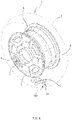
Fig. 1 is a perspective view of a tire pressure detector in accordance with an embodiment of the present invention. -
Fig. 2 is a sectional view of the tire pressure detector, illustrating the main body provided with a bore. -
Fig. 3 is another sectional view of the tire pressure detector, illustrating the main body provided with a channel. -
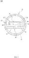
Fig. 4 is a schematic view of an embodiment of the present invention illustrating the tire pressure detector placed in the pressure space of the wheel. -
Fig. 5 is a sectional view of an embodiment of the present invention illustrating the main body rolling in the pressure space of the wheel. -
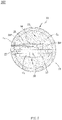
Fig. 6 is a schematic view of another embodiment of the present invention illustrating the balancing member and the tire pressure detector placed in the pressure space. -
Fig. 7 is a sectional view of another embodiment of the present invention illustrating the balancing member and the tire pressure detector rolling in the pressure space of the wheel. - The aforementioned and further advantages and features of the present invention will be understood by reference to the description of the preferred embodiment in conjunction with the accompanying drawings where the components are illustrated based on a proportion for explanation but not subject to the actual component proportion.
- The amount of components defined by the texts "a", "an", and "the" used in the singular form includes the embodiments of the plurality forms in the present invention, unless being otherwise defined by the context of the specification. It shall be understood that the texts such as "include" and/or "comprise" indicate that such technical features, bodies, members, modules, and/or units exist among other technical features, bodies, members, modules, and/or units, instead of excluding the existence of others.
- When one element/component is mentioned as being "on" or "above", or being "connected", "coupled with", or "combined with" another element/component, it shall be understood that the element/component is disposed on, coupled with, connected with, or combined with the other element/component directly or indirectly with intermediate element/component therebetween.
- Referring to
Fig. 1 to Fig. 5 , atire pressure detector 100 with wheel balancing function is provided, which is operated at a vehicle wheel, including the wheel of a motorcycle or a car. In an embodiment of the present invention, the vehicle refers to a car. Thewheel 1 comprises arim 2 and atire 3 mounted around therim 2. Therim 2 is provided with an outer surface 4 and anouter wall 5. The outer surface 4 faces one end of the rotational axis of the wheel, and theouter wall 5 surrounds the rotational axis of thewheel 1. Thetire 3 comprises anouter tire face 6 and aninner tire face 7, wherein theinner tire face 7 of thetire 3 faces theouter wall 5 of therim 2 and is mounted around therim 2, with apressure space 8 formed between theinner tire face 7 of thetire 3 and theouter wall 5 of therim 2. When the car moves, theouter tire face 6 of thetire 3 contacts the ground. Also, the outer surface 4 of therim 2 is provided with anair tap 9 which is connected with thepressure space 8, wherein theair tap 9 input air into thepressure space 8. - The
tire pressure detector 100 comprises amain body 10 and thedetection module 20. Thedetection module 20 is disposed in ahousing space 11 inside themain body 10. Themain body 10 is movably disposed in thepressure space 8 for balancing the mass of thewheel 1 and detecting the air pressure in thepressure space 8 through asensing unit 21 of thedetection module 20. Therefore, the present invention achieves both the tire pressure detection and wheel balancing functions. - The
main body 10 includes anouter edge 12. The shape of themain body 10 is allowed to be ball-shaped, an oval-shaped, or a polygonal-shaped. In an embodiment of the present invention, themain body 10 is ball-shaped. When thewheel 1 rotates to move the vehicle, the centrifugal force of thewheel 1 causes theouter edge 12 of themain body 10 to roll along the tangent line of the movingwheel 1 and contact theinner tire face 7 of the tire. Therefore, the imbalance vibration caused by thewheel 1 and components thereof are counteracted by use of a dynamic balancing effect. Also, the mass of thewheel 1 is balanced, so as to maintain the balance of thewheel 1. In addition, themain body 10 is allowed to be applied in an amount of one or more. The user is able to adjust the amount of themain body 10 according to different demands or class of the vehicle. In an embodiment of the present invention, a plurality ofmain bodies 10 are provided. - The
detection module 20 is provided with acircuit substrate 22, asensing unit 21 disposed at thecircuit substrate 22, and acentral processing unit 23, awireless transmission unit 24, and apower unit 25 that are coupled with thesensing unit 21, wherein thepower unit 25 provides a power. In an embodiment of the present invention, thesensing unit 21, thecentral processing unit 23, and thewireless transmission unit 24 are integrated. Thewireless transmission unit 24 includes afirst antenna section 241, asecond antenna section 242 being bent by an angle with respect to thefirst antenna section 241, and atransition section 243 between thefirst antenna section 241 and thesecond antenna section 242. In an embodiment of the present invention, both thefirst antenna section 241 and thesecond antenna section 242 are formed in a straight line shape, respectively, the angle included by the first section and the second section is preferably ninety degrees, and thefirst antenna section 241, thesecond antenna section 242, and thetransition portion 243 are arranged in parallel to thecircuit substrate 22. Thewireless transmission unit 24 is allowed to be a Bluetooth structure or radio frequency antenna. The radio frequency antenna is able to be a sub-lGHz antenna; in other words, the frequency of the radio frequency antenna is lower than 1 GHz, such as 315MHz, 434MHz, 868MHz, or 915MHz. Thepower unit 25 is a battery. - Referring to
Fig. 2 andFig. 4 , in an embodiment of the present invention, themain body 10 is provided with abore 13 connected with thehousing space 11 and thepressure space 8. Thecircuit substrate 22 is fixed in thehousing space 11, so as to fix thedetection module 20 to themain body 10. Air in thepressure space 8 enters thehousing space 11 through thebore 13. Referring toFig. 3 andFig. 4 , in another embodiment of the present invention, themain body 10 is provided with achannel 14 which is connected with thepressure space 8 and thesensing unit 21. Thedetection module 20 is fixed in thehousing space 11 of themain body 10 by an adheringmember 30, wherein the adheringmember 30 fills thehousing space 11. Thesensing unit 21 detects the air pressure in thepressure space 8 through thechannel 14. In the embodiment, the adheringmember 30 is a glue. - When the
sensing unit 21 detects the air pressure in thepressure space 8, thesensing unit 21 produces a pressure signal, which is sent to thecentral processing unit 23. Thecentral processing unit 23 receives the pressure signal, and transmits the pressure signal through thewireless transmission unit 24, wherein thewireless transmission unit 24 is wirelessly connected with the electronic control unit (ECU) of the car. Upon receiving the pressure signal, the electronic control unit displays the air pressure of thepressure space 8, or sends out a warning signal when an abnormality of the air pressure in thepressure space 8 occurs, thereby informing the driver. The electrical control unit is an information interface chosen from a panel board, digital displayer, light signals, or sound. - Therefore, by directly placing the
main body 10 provided with thedetection module 20 in thepressure space 8, themain body 10 is allowed to move in thepressure space 8 of thetire 3 during the movement of thewheel 1, thereby detecting the air pressure in thepressure space 8, thus achieving an installation easiness and a convenience of usage. Also, the issue of a mass imbalance of thewheel 1 is avoided. - The pressure signal produced by the
sensing unit 21 is able to be stably sent to thecentral processing unit 23 when themain body 10 moves with the rotation of thewheel 1, since thewireless transmission unit 24 of the present invention is nondirectional. - Also, the
main body 10 rollers to contact theinner tire face 7 of thetire 3 during the movement of thewheel 1, such that themain body 10 is able to counteract the imbalance vibration caused by thewheel 1 and the components thereof in a manner of dynamic balance, thus balancing the mass of thewheel 1 and reducing the vibration of thewheel 1. Therefore, the present invention achieves both the tire pressure detection and the wheel balancing functions. - Referring to
Fig. 6 to Fig. 7 , in another embodiment of the present invention, a wheel balancing system applying the aforementionedtire pressure detector 100 is provided, which further comprises a plurality of balancingbodies 40. - The balancing
bodies 40 are movably disposed in thepressure space 8 along with thetire pressure detectors 100. In an embodiment of the present invention, the shape of the balancingbodies 40 is identical to the shape of themain body 10 of thetire pressure detectors 100. Also, size of the balancingbodies 40 and themain bodies 10 are able to be identical or similar according to different demands. Further, when multipletire pressure detectors 100 are provided, the amount of thetire pressure detectors 100 is allowed to be larger than, smaller than, or equal to the amount of the balancingbodies 40. The user is able to adjust the amounts of the balancingbodies 40 and thetire pressure detectors 100. In an embodiment of the present invention, the amount of thetire pressure detectors 100 is identical to the amount of the balancingbodies 40. - Thus, when the
wheel 1 rotates to drive the car to move, the centrifugal force of the rotation of thewheel 1 causes the balancingbodies 40 andouter edge 12 of themain bodies 10 to contact theinner tire face 7 of thetire 3 along the tangent direction of the movingwheel 1. With the dynamic balance upon thewheel 1 by the balancingbodies 40 and themain bodies 10, the imbalance vibration caused by thewheel 1 and the components thereof are counteracted, thus achieving the balance of thewheel 1. - Although particular embodiments of the invention have been described in detail for purposes of illustration, various modifications and enhancements may be made without departing from the scope of the invention.
- The invention is defined by the appended claims.
Claims (11)
- A tire pressure detector (100) disposed at a wheel (1), wherein the wheel (1) includes a rim (2) and a tire (3) mounted around the rim (2), with a pressure space (8) formed between the tire (3) and the rim (2), the rim (2) including an air tap (9) connected with the pressure space (8), the tire pressure detector (100) comprising a main body (10) and a detection module (20), whereinthe main body (10) is movably disposed in the pressure space (8) and is provided with a housing space (11); andthe detection module (20) is disposed in the housing space (11), the detection module (20) further including a sensing unit (21), a circuit substrate (22), a central processing unit (23), a wireless transmission unit (24) and a power unit (25) that are coupled with each other, the power unit (25) providing a power, the sensing unit (21), the wireless transmission unit (24) and the power unit (25) disposed on the circuit substrate (22), characterized in that the wireless transmission unit (24) has a first antenna section (241), a second antenna section (242) being bent by an angle with respect to the first antenna section (241), and a transition section (243) between the first antenna section (241) and the second antenna section (242); the first antenna section (241) and the second antenna section (242) being formed in a straight line shape, respectively; the angle included by the first section and the second section being ninety degrees; the first antenna section (241), the second antenna section (242), and the transition portion (243) being arranged in parallel to the circuit substrate (22); the sensing unit (21) sensing an air pressure in the pressure space (8) and producing a pressure signal, the central processing unit (23) receiving the pressure signal and transmitting the pressure signal through the wireless transmission unit (24).
- The tire pressure detector (100) of claim 1, wherein the main body (10) is rotatably disposed in the pressure space (8).
- The tire pressure detector (100) of claim 2, wherein the main body (10) includes an outer edge (12), the outer edge (12) contacting an inner tire face (7) of the tire (3) along a tangent direction of the moving wheel (1).
- The tire pressure detector (100) of claim 1, wherein a shape of the main body (10) is chosen from the group consisting of a ball, an oval, and a polygonal shape.
- The tire pressure detector (100) of claim 4, wherein a plurality of the main bodies (10) are provided.
- The tire pressure detector (100) of claim 1, wherein the circuit substrate (22) is fixed in the housing space (11).
- The tire pressure detector (100) of claim 1, wherein the main body (10) is provided with a bore (13) connected with the housing space (11) and the pressure space (8), such that the sensing unit (21) senses the air pressure in the pressure space (8).
- The tire pressure detector (100) of claim 1, wherein the detection module (20) is fixed in the housing space (11) through an adhering member (30).
- The tire pressure detector (100) of claim 8, wherein the main body (10) includes a channel (14) connected with the pressure space (8) and the sensing unit (21).
- The tire pressure detector (100) of claim 1, further comprising:
a plurality of balancing bodies (40) movably disposed in the pressure space (8) along with the tire pressure detector (100). - The tire pressure detector (100) of claim 10, wherein a shape of the balancing bodies (40) is identical to a shape of the main body (10) of the tire pressure detector (100).
Applications Claiming Priority (1)
| Application Number | Priority Date | Filing Date | Title |
|---|---|---|---|
| TW106135037A TWI643765B (en) | 2017-10-13 | 2017-10-13 | Tire pressure detector with wheel balancing function and the wheel balancing system thereof |
Publications (2)
| Publication Number | Publication Date |
|---|---|
| EP3470245A1 EP3470245A1 (en) | 2019-04-17 |
| EP3470245B1 true EP3470245B1 (en) | 2023-01-11 |
Family
ID=61189306
Family Applications (1)
| Application Number | Title | Priority Date | Filing Date |
|---|---|---|---|
| EP18156008.7A Active EP3470245B1 (en) | 2017-10-13 | 2018-02-09 | Tire pressure detector with wheel balancing function and wheel balancing system thereof |
Country Status (3)
| Country | Link |
|---|---|
| US (1) | US10675921B2 (en) |
| EP (1) | EP3470245B1 (en) |
| TW (1) | TWI643765B (en) |
Families Citing this family (1)
| Publication number | Priority date | Publication date | Assignee | Title |
|---|---|---|---|---|
| JP7227082B2 (en) * | 2019-06-12 | 2023-02-21 | 株式会社ブリヂストン | Pneumatic tire and method for manufacturing pneumatic tire |
Family Cites Families (15)
| Publication number | Priority date | Publication date | Assignee | Title |
|---|---|---|---|---|
| US3724904A (en) * | 1970-03-26 | 1973-04-03 | C Nixon | Wheel balancing device |
| US6082192A (en) * | 1998-11-13 | 2000-07-04 | Bridgestone/Firestone, Inc. | Non-attached monitoring assembly for pneumatic tire |
| US6360594B1 (en) * | 1998-11-13 | 2002-03-26 | Bridgestone/Firestone North American Tire, Llc | Non-attached monitoring assembly for pneumatic tire |
| US6722191B2 (en) * | 1998-11-13 | 2004-04-20 | Bridgestone/Firestone North American Tire, Llc | Non-attached monitoring assembly for pneumatic tire |
| US6543277B2 (en) * | 1998-11-13 | 2003-04-08 | Bridgestone/Firestone North American Tire, Llc | Non-attached monitoring assembly for pneumatic tire |
| JP4524364B2 (en) * | 2003-02-04 | 2010-08-18 | ブリヂストン アメリカズ タイヤ オペレイションズ エルエルシー | Non-mounted tire monitoring device |
| US6910372B2 (en) * | 2003-03-21 | 2005-06-28 | Bridgestone/Firestone North American Tire, Llc | Non-attached electronic monitoring device for tire |
| JP2006168478A (en) * | 2004-12-14 | 2006-06-29 | Bridgestone Corp | Tire particle aggregate |
| US7107830B1 (en) * | 2004-12-20 | 2006-09-19 | Mobiletron Electronics Co., Ltd. | Wireless tire pressure monitoring system (WTPMS) dual-sectional monitor signal transmission module |
| US20060196259A1 (en) * | 2005-03-02 | 2006-09-07 | Chin-Yao Hsu | Aerial of wireless tire pressure monitoring device |
| US7775097B1 (en) * | 2009-03-26 | 2010-08-17 | Sung Jung Minute Industry Co., Ltd. | Tire pressure detector |
| CN102514455B (en) * | 2011-10-31 | 2014-02-26 | 香港应用科技研究院有限公司 | Tire pressure monitoring system without assembly |
| US8939020B2 (en) * | 2012-12-05 | 2015-01-27 | Caterpillar Inc. | Spherical monitoring device for pneumatic tires |
| CN203948720U (en) * | 2014-06-09 | 2014-11-19 | 怡利电子工业股份有限公司 | Intensifier valve for tire pressure monitoring device |
| CN204915143U (en) * | 2015-08-28 | 2015-12-30 | 大陆汽车电子(长春)有限公司 | Built -in tire pressure sensor |
-
2017
- 2017-10-13 TW TW106135037A patent/TWI643765B/en active
-
2018
- 2018-02-09 EP EP18156008.7A patent/EP3470245B1/en active Active
- 2018-02-23 US US15/903,933 patent/US10675921B2/en active Active
Also Published As
| Publication number | Publication date |
|---|---|
| US20190111740A1 (en) | 2019-04-18 |
| US10675921B2 (en) | 2020-06-09 |
| TW201914844A (en) | 2019-04-16 |
| TWI643765B (en) | 2018-12-11 |
| EP3470245A1 (en) | 2019-04-17 |
Similar Documents
| Publication | Publication Date | Title |
|---|---|---|
| US6082192A (en) | Non-attached monitoring assembly for pneumatic tire | |
| US7673505B2 (en) | Tire footprint determination apparatuses, systems and methods | |
| JP3884007B2 (en) | System and method for monitoring vehicle conditions affecting tires | |
| JP2008049999A (en) | Aircraft tire condition monitoring system and method | |
| CN107672389A (en) | Tyre pressure sensor and wheel balancing systems with wheel balance effect | |
| CN108327466A (en) | Tyre pressure sensor with shell protection | |
| US10675921B2 (en) | Tire pressure detector with wheel balancing function and wheel balancing system thereof | |
| JP2003182321A (en) | Transmitter of tyre state monitoring device | |
| US7741963B2 (en) | Wheel data detection system | |
| TWI736743B (en) | Non-fixed tire pressure detector | |
| US10583701B2 (en) | Tire pressure detector with protection shell | |
| CN108263150A (en) | The tire pressure detector of free-standing | |
| CN108284717A (en) | Tire pressure detector with centre-of gravity shift | |
| CN108099490B (en) | Explosion-proof wheel hub | |
| CN208085414U (en) | Tire pressure detector with centre-of gravity shift | |
| TWI706871B (en) | Tire pressure detector with center of gravity shift | |
| CN207403505U (en) | Tyre pressure sensor and wheel balancing systems with wheel balance effect | |
| CN108973537A (en) | A kind of tire wear detection device and tire wear detection method | |
| JP6712572B2 (en) | Vehicle self-monitoring tires | |
| CN103241077B (en) | A kind of TPMS system | |
| CN207772804U (en) | A kind of spherical shape tire pressure sensing device and tire pressure monitoring system | |
| JP2007112163A (en) | Wheel sensor device | |
| KR200450432Y1 (en) | Pressure sensor for tire pressure measurement and tire air pressure monitoring system | |
| TWM600255U (en) | Rim hole type tire monitoring stucture | |
| WO2005047029A1 (en) | Tire monitoring system |
Legal Events
| Date | Code | Title | Description |
|---|---|---|---|
| PUAI | Public reference made under article 153(3) epc to a published international application that has entered the european phase |
Free format text: ORIGINAL CODE: 0009012 |
|
| STAA | Information on the status of an ep patent application or granted ep patent |
Free format text: STATUS: THE APPLICATION HAS BEEN PUBLISHED |
|
| AK | Designated contracting states |
Kind code of ref document: A1 Designated state(s): AL AT BE BG CH CY CZ DE DK EE ES FI FR GB GR HR HU IE IS IT LI LT LU LV MC MK MT NL NO PL PT RO RS SE SI SK SM TR |
|
| AX | Request for extension of the european patent |
Extension state: BA ME |
|
| STAA | Information on the status of an ep patent application or granted ep patent |
Free format text: STATUS: REQUEST FOR EXAMINATION WAS MADE |
|
| 17P | Request for examination filed |
Effective date: 20191017 |
|
| RBV | Designated contracting states (corrected) |
Designated state(s): AL AT BE BG CH CY CZ DE DK EE ES FI FR GB GR HR HU IE IS IT LI LT LU LV MC MK MT NL NO PL PT RO RS SE SI SK SM TR |
|
| STAA | Information on the status of an ep patent application or granted ep patent |
Free format text: STATUS: EXAMINATION IS IN PROGRESS |
|
| 17Q | First examination report despatched |
Effective date: 20210922 |
|
| GRAP | Despatch of communication of intention to grant a patent |
Free format text: ORIGINAL CODE: EPIDOSNIGR1 |
|
| STAA | Information on the status of an ep patent application or granted ep patent |
Free format text: STATUS: GRANT OF PATENT IS INTENDED |
|
| INTG | Intention to grant announced |
Effective date: 20220721 |
|
| GRAS | Grant fee paid |
Free format text: ORIGINAL CODE: EPIDOSNIGR3 |
|
| GRAA | (expected) grant |
Free format text: ORIGINAL CODE: 0009210 |
|
| STAA | Information on the status of an ep patent application or granted ep patent |
Free format text: STATUS: THE PATENT HAS BEEN GRANTED |
|
| AK | Designated contracting states |
Kind code of ref document: B1 Designated state(s): AL AT BE BG CH CY CZ DE DK EE ES FI FR GB GR HR HU IE IS IT LI LT LU LV MC MK MT NL NO PL PT RO RS SE SI SK SM TR |
|
| REG | Reference to a national code |
Ref country code: GB Ref legal event code: FG4D |
|
| REG | Reference to a national code |
Ref country code: CH Ref legal event code: EP |
|
| REG | Reference to a national code |
Ref country code: DE Ref legal event code: R096 Ref document number: 602018045217 Country of ref document: DE |
|
| REG | Reference to a national code |
Ref country code: IE Ref legal event code: FG4D |
|
| REG | Reference to a national code |
Ref country code: AT Ref legal event code: REF Ref document number: 1543210 Country of ref document: AT Kind code of ref document: T Effective date: 20230215 |
|
| REG | Reference to a national code |
Ref country code: SE Ref legal event code: TRGR |
|
| PGFP | Annual fee paid to national office [announced via postgrant information from national office to epo] |
Ref country code: FR Payment date: 20230125 Year of fee payment: 6 |
|
| REG | Reference to a national code |
Ref country code: LT Ref legal event code: MG9D |
|
| REG | Reference to a national code |
Ref country code: NL Ref legal event code: MP Effective date: 20230111 |
|
| PGFP | Annual fee paid to national office [announced via postgrant information from national office to epo] |
Ref country code: SE Payment date: 20230203 Year of fee payment: 6 |
|
| REG | Reference to a national code |
Ref country code: AT Ref legal event code: MK05 Ref document number: 1543210 Country of ref document: AT Kind code of ref document: T Effective date: 20230111 |
|
| PG25 | Lapsed in a contracting state [announced via postgrant information from national office to epo] |
Ref country code: NL Free format text: LAPSE BECAUSE OF FAILURE TO SUBMIT A TRANSLATION OF THE DESCRIPTION OR TO PAY THE FEE WITHIN THE PRESCRIBED TIME-LIMIT Effective date: 20230111 |
|
| PG25 | Lapsed in a contracting state [announced via postgrant information from national office to epo] |
Ref country code: RS Free format text: LAPSE BECAUSE OF FAILURE TO SUBMIT A TRANSLATION OF THE DESCRIPTION OR TO PAY THE FEE WITHIN THE PRESCRIBED TIME-LIMIT Effective date: 20230111 Ref country code: PT Free format text: LAPSE BECAUSE OF FAILURE TO SUBMIT A TRANSLATION OF THE DESCRIPTION OR TO PAY THE FEE WITHIN THE PRESCRIBED TIME-LIMIT Effective date: 20230511 Ref country code: NO Free format text: LAPSE BECAUSE OF FAILURE TO SUBMIT A TRANSLATION OF THE DESCRIPTION OR TO PAY THE FEE WITHIN THE PRESCRIBED TIME-LIMIT Effective date: 20230411 Ref country code: LV Free format text: LAPSE BECAUSE OF FAILURE TO SUBMIT A TRANSLATION OF THE DESCRIPTION OR TO PAY THE FEE WITHIN THE PRESCRIBED TIME-LIMIT Effective date: 20230111 Ref country code: LT Free format text: LAPSE BECAUSE OF FAILURE TO SUBMIT A TRANSLATION OF THE DESCRIPTION OR TO PAY THE FEE WITHIN THE PRESCRIBED TIME-LIMIT Effective date: 20230111 Ref country code: HR Free format text: LAPSE BECAUSE OF FAILURE TO SUBMIT A TRANSLATION OF THE DESCRIPTION OR TO PAY THE FEE WITHIN THE PRESCRIBED TIME-LIMIT Effective date: 20230111 Ref country code: ES Free format text: LAPSE BECAUSE OF FAILURE TO SUBMIT A TRANSLATION OF THE DESCRIPTION OR TO PAY THE FEE WITHIN THE PRESCRIBED TIME-LIMIT Effective date: 20230111 Ref country code: AT Free format text: LAPSE BECAUSE OF FAILURE TO SUBMIT A TRANSLATION OF THE DESCRIPTION OR TO PAY THE FEE WITHIN THE PRESCRIBED TIME-LIMIT Effective date: 20230111 |
|
| PG25 | Lapsed in a contracting state [announced via postgrant information from national office to epo] |
Ref country code: PL Free format text: LAPSE BECAUSE OF FAILURE TO SUBMIT A TRANSLATION OF THE DESCRIPTION OR TO PAY THE FEE WITHIN THE PRESCRIBED TIME-LIMIT Effective date: 20230111 Ref country code: IS Free format text: LAPSE BECAUSE OF FAILURE TO SUBMIT A TRANSLATION OF THE DESCRIPTION OR TO PAY THE FEE WITHIN THE PRESCRIBED TIME-LIMIT Effective date: 20230511 Ref country code: GR Free format text: LAPSE BECAUSE OF FAILURE TO SUBMIT A TRANSLATION OF THE DESCRIPTION OR TO PAY THE FEE WITHIN THE PRESCRIBED TIME-LIMIT Effective date: 20230412 Ref country code: FI Free format text: LAPSE BECAUSE OF FAILURE TO SUBMIT A TRANSLATION OF THE DESCRIPTION OR TO PAY THE FEE WITHIN THE PRESCRIBED TIME-LIMIT Effective date: 20230111 |
|
| REG | Reference to a national code |
Ref country code: CH Ref legal event code: PL |
|
| REG | Reference to a national code |
Ref country code: DE Ref legal event code: R097 Ref document number: 602018045217 Country of ref document: DE |
|
| REG | Reference to a national code |
Ref country code: BE Ref legal event code: MM Effective date: 20230228 |
|
| PG25 | Lapsed in a contracting state [announced via postgrant information from national office to epo] |
Ref country code: SM Free format text: LAPSE BECAUSE OF FAILURE TO SUBMIT A TRANSLATION OF THE DESCRIPTION OR TO PAY THE FEE WITHIN THE PRESCRIBED TIME-LIMIT Effective date: 20230111 Ref country code: RO Free format text: LAPSE BECAUSE OF FAILURE TO SUBMIT A TRANSLATION OF THE DESCRIPTION OR TO PAY THE FEE WITHIN THE PRESCRIBED TIME-LIMIT Effective date: 20230111 Ref country code: MC Free format text: LAPSE BECAUSE OF FAILURE TO SUBMIT A TRANSLATION OF THE DESCRIPTION OR TO PAY THE FEE WITHIN THE PRESCRIBED TIME-LIMIT Effective date: 20230111 Ref country code: LU Free format text: LAPSE BECAUSE OF NON-PAYMENT OF DUE FEES Effective date: 20230209 Ref country code: LI Free format text: LAPSE BECAUSE OF NON-PAYMENT OF DUE FEES Effective date: 20230228 Ref country code: EE Free format text: LAPSE BECAUSE OF FAILURE TO SUBMIT A TRANSLATION OF THE DESCRIPTION OR TO PAY THE FEE WITHIN THE PRESCRIBED TIME-LIMIT Effective date: 20230111 Ref country code: DK Free format text: LAPSE BECAUSE OF FAILURE TO SUBMIT A TRANSLATION OF THE DESCRIPTION OR TO PAY THE FEE WITHIN THE PRESCRIBED TIME-LIMIT Effective date: 20230111 Ref country code: CZ Free format text: LAPSE BECAUSE OF FAILURE TO SUBMIT A TRANSLATION OF THE DESCRIPTION OR TO PAY THE FEE WITHIN THE PRESCRIBED TIME-LIMIT Effective date: 20230111 Ref country code: CH Free format text: LAPSE BECAUSE OF NON-PAYMENT OF DUE FEES Effective date: 20230228 |
|
| PLBE | No opposition filed within time limit |
Free format text: ORIGINAL CODE: 0009261 |
|
| STAA | Information on the status of an ep patent application or granted ep patent |
Free format text: STATUS: NO OPPOSITION FILED WITHIN TIME LIMIT |
|
| PG25 | Lapsed in a contracting state [announced via postgrant information from national office to epo] |
Ref country code: SK Free format text: LAPSE BECAUSE OF FAILURE TO SUBMIT A TRANSLATION OF THE DESCRIPTION OR TO PAY THE FEE WITHIN THE PRESCRIBED TIME-LIMIT Effective date: 20230111 |
|
| 26N | No opposition filed |
Effective date: 20231012 |
|
| REG | Reference to a national code |
Ref country code: IE Ref legal event code: MM4A |
|
| PG25 | Lapsed in a contracting state [announced via postgrant information from national office to epo] |
Ref country code: SI Free format text: LAPSE BECAUSE OF FAILURE TO SUBMIT A TRANSLATION OF THE DESCRIPTION OR TO PAY THE FEE WITHIN THE PRESCRIBED TIME-LIMIT Effective date: 20230111 Ref country code: IE Free format text: LAPSE BECAUSE OF NON-PAYMENT OF DUE FEES Effective date: 20230209 |
|
| PG25 | Lapsed in a contracting state [announced via postgrant information from national office to epo] |
Ref country code: BE Free format text: LAPSE BECAUSE OF NON-PAYMENT OF DUE FEES Effective date: 20230228 |
|
| PG25 | Lapsed in a contracting state [announced via postgrant information from national office to epo] |
Ref country code: IT Free format text: LAPSE BECAUSE OF FAILURE TO SUBMIT A TRANSLATION OF THE DESCRIPTION OR TO PAY THE FEE WITHIN THE PRESCRIBED TIME-LIMIT Effective date: 20230111 |
|
| REG | Reference to a national code |
Ref country code: SE Ref legal event code: EUG |
|
| PG25 | Lapsed in a contracting state [announced via postgrant information from national office to epo] |
Ref country code: BG Free format text: LAPSE BECAUSE OF FAILURE TO SUBMIT A TRANSLATION OF THE DESCRIPTION OR TO PAY THE FEE WITHIN THE PRESCRIBED TIME-LIMIT Effective date: 20230111 |
|
| PG25 | Lapsed in a contracting state [announced via postgrant information from national office to epo] |
Ref country code: BG Free format text: LAPSE BECAUSE OF FAILURE TO SUBMIT A TRANSLATION OF THE DESCRIPTION OR TO PAY THE FEE WITHIN THE PRESCRIBED TIME-LIMIT Effective date: 20230111 |
|
| PG25 | Lapsed in a contracting state [announced via postgrant information from national office to epo] |
Ref country code: FR Free format text: LAPSE BECAUSE OF NON-PAYMENT OF DUE FEES Effective date: 20240229 |
|
| PG25 | Lapsed in a contracting state [announced via postgrant information from national office to epo] |
Ref country code: FR Free format text: LAPSE BECAUSE OF NON-PAYMENT OF DUE FEES Effective date: 20240229 |
|
| PG25 | Lapsed in a contracting state [announced via postgrant information from national office to epo] |
Ref country code: CY Free format text: LAPSE BECAUSE OF FAILURE TO SUBMIT A TRANSLATION OF THE DESCRIPTION OR TO PAY THE FEE WITHIN THE PRESCRIBED TIME-LIMIT; INVALID AB INITIO Effective date: 20180209 |
|
| PG25 | Lapsed in a contracting state [announced via postgrant information from national office to epo] |
Ref country code: HU Free format text: LAPSE BECAUSE OF FAILURE TO SUBMIT A TRANSLATION OF THE DESCRIPTION OR TO PAY THE FEE WITHIN THE PRESCRIBED TIME-LIMIT; INVALID AB INITIO Effective date: 20180209 |
|
| PG25 | Lapsed in a contracting state [announced via postgrant information from national office to epo] |
Ref country code: SE Free format text: LAPSE BECAUSE OF NON-PAYMENT OF DUE FEES Effective date: 20240210 |
|
| PG25 | Lapsed in a contracting state [announced via postgrant information from national office to epo] |
Ref country code: TR Free format text: LAPSE BECAUSE OF FAILURE TO SUBMIT A TRANSLATION OF THE DESCRIPTION OR TO PAY THE FEE WITHIN THE PRESCRIBED TIME-LIMIT Effective date: 20230111 |
|
| PGFP | Annual fee paid to national office [announced via postgrant information from national office to epo] |
Ref country code: GB Payment date: 20260226 Year of fee payment: 9 |
|
| PGFP | Annual fee paid to national office [announced via postgrant information from national office to epo] |
Ref country code: DE Payment date: 20260204 Year of fee payment: 9 |