EP3470224A1 - Coated article and method for making - Google Patents
Coated article and method for making Download PDFInfo
- Publication number
- EP3470224A1 EP3470224A1 EP18195399.3A EP18195399A EP3470224A1 EP 3470224 A1 EP3470224 A1 EP 3470224A1 EP 18195399 A EP18195399 A EP 18195399A EP 3470224 A1 EP3470224 A1 EP 3470224A1
- Authority
- EP
- European Patent Office
- Prior art keywords
- metal
- interface
- substrate
- overlay
- coating
- Prior art date
- Legal status (The legal status is an assumption and is not a legal conclusion. Google has not performed a legal analysis and makes no representation as to the accuracy of the status listed.)
- Granted
Links
Images
Classifications
-
- C—CHEMISTRY; METALLURGY
- C23—COATING METALLIC MATERIAL; COATING MATERIAL WITH METALLIC MATERIAL; CHEMICAL SURFACE TREATMENT; DIFFUSION TREATMENT OF METALLIC MATERIAL; COATING BY VACUUM EVAPORATION, BY SPUTTERING, BY ION IMPLANTATION OR BY CHEMICAL VAPOUR DEPOSITION, IN GENERAL; INHIBITING CORROSION OF METALLIC MATERIAL OR INCRUSTATION IN GENERAL
- C23C—COATING METALLIC MATERIAL; COATING MATERIAL WITH METALLIC MATERIAL; SURFACE TREATMENT OF METALLIC MATERIAL BY DIFFUSION INTO THE SURFACE, BY CHEMICAL CONVERSION OR SUBSTITUTION; COATING BY VACUUM EVAPORATION, BY SPUTTERING, BY ION IMPLANTATION OR BY CHEMICAL VAPOUR DEPOSITION, IN GENERAL
- C23C4/00—Coating by spraying the coating material in the molten state, e.g. by flame, plasma or electric discharge
- C23C4/04—Coating by spraying the coating material in the molten state, e.g. by flame, plasma or electric discharge characterised by the coating material
- C23C4/06—Metallic material
- C23C4/08—Metallic material containing only metal elements
-
- C—CHEMISTRY; METALLURGY
- C23—COATING METALLIC MATERIAL; COATING MATERIAL WITH METALLIC MATERIAL; CHEMICAL SURFACE TREATMENT; DIFFUSION TREATMENT OF METALLIC MATERIAL; COATING BY VACUUM EVAPORATION, BY SPUTTERING, BY ION IMPLANTATION OR BY CHEMICAL VAPOUR DEPOSITION, IN GENERAL; INHIBITING CORROSION OF METALLIC MATERIAL OR INCRUSTATION IN GENERAL
- C23C—COATING METALLIC MATERIAL; COATING MATERIAL WITH METALLIC MATERIAL; SURFACE TREATMENT OF METALLIC MATERIAL BY DIFFUSION INTO THE SURFACE, BY CHEMICAL CONVERSION OR SUBSTITUTION; COATING BY VACUUM EVAPORATION, BY SPUTTERING, BY ION IMPLANTATION OR BY CHEMICAL VAPOUR DEPOSITION, IN GENERAL
- C23C30/00—Coating with metallic material characterised only by the composition of the metallic material, i.e. not characterised by the coating process
-
- B—PERFORMING OPERATIONS; TRANSPORTING
- B23—MACHINE TOOLS; METAL-WORKING NOT OTHERWISE PROVIDED FOR
- B23K—SOLDERING OR UNSOLDERING; WELDING; CLADDING OR PLATING BY SOLDERING OR WELDING; CUTTING BY APPLYING HEAT LOCALLY, e.g. FLAME CUTTING; WORKING BY LASER BEAM
- B23K35/00—Rods, electrodes, materials, or media, for use in soldering, welding, or cutting
- B23K35/22—Rods, electrodes, materials, or media, for use in soldering, welding, or cutting characterised by the composition or nature of the material
- B23K35/24—Selection of soldering or welding materials proper
- B23K35/30—Selection of soldering or welding materials proper with the principal constituent melting at less than 1550°C
- B23K35/3053—Fe as the principal constituent
- B23K35/308—Fe as the principal constituent with Cr as next major constituent
-
- B—PERFORMING OPERATIONS; TRANSPORTING
- B32—LAYERED PRODUCTS
- B32B—LAYERED PRODUCTS, i.e. PRODUCTS BUILT-UP OF STRATA OF FLAT OR NON-FLAT, e.g. CELLULAR OR HONEYCOMB, FORM
- B32B15/00—Layered products comprising a layer of metal
- B32B15/01—Layered products comprising a layer of metal all layers being exclusively metallic
-
- B—PERFORMING OPERATIONS; TRANSPORTING
- B32—LAYERED PRODUCTS
- B32B—LAYERED PRODUCTS, i.e. PRODUCTS BUILT-UP OF STRATA OF FLAT OR NON-FLAT, e.g. CELLULAR OR HONEYCOMB, FORM
- B32B15/00—Layered products comprising a layer of metal
- B32B15/01—Layered products comprising a layer of metal all layers being exclusively metallic
- B32B15/013—Layered products comprising a layer of metal all layers being exclusively metallic one layer being formed of an iron alloy or steel, another layer being formed of a metal other than iron or aluminium
-
- B—PERFORMING OPERATIONS; TRANSPORTING
- B32—LAYERED PRODUCTS
- B32B—LAYERED PRODUCTS, i.e. PRODUCTS BUILT-UP OF STRATA OF FLAT OR NON-FLAT, e.g. CELLULAR OR HONEYCOMB, FORM
- B32B15/00—Layered products comprising a layer of metal
- B32B15/01—Layered products comprising a layer of metal all layers being exclusively metallic
- B32B15/013—Layered products comprising a layer of metal all layers being exclusively metallic one layer being formed of an iron alloy or steel, another layer being formed of a metal other than iron or aluminium
- B32B15/015—Layered products comprising a layer of metal all layers being exclusively metallic one layer being formed of an iron alloy or steel, another layer being formed of a metal other than iron or aluminium the said other metal being copper or nickel or an alloy thereof
-
- C—CHEMISTRY; METALLURGY
- C09—DYES; PAINTS; POLISHES; NATURAL RESINS; ADHESIVES; COMPOSITIONS NOT OTHERWISE PROVIDED FOR; APPLICATIONS OF MATERIALS NOT OTHERWISE PROVIDED FOR
- C09D—COATING COMPOSITIONS, e.g. PAINTS, VARNISHES OR LACQUERS; FILLING PASTES; CHEMICAL PAINT OR INK REMOVERS; INKS; CORRECTING FLUIDS; WOODSTAINS; PASTES OR SOLIDS FOR COLOURING OR PRINTING; USE OF MATERIALS THEREFOR
- C09D1/00—Coating compositions, e.g. paints, varnishes or lacquers, based on inorganic substances
-
- C—CHEMISTRY; METALLURGY
- C09—DYES; PAINTS; POLISHES; NATURAL RESINS; ADHESIVES; COMPOSITIONS NOT OTHERWISE PROVIDED FOR; APPLICATIONS OF MATERIALS NOT OTHERWISE PROVIDED FOR
- C09D—COATING COMPOSITIONS, e.g. PAINTS, VARNISHES OR LACQUERS; FILLING PASTES; CHEMICAL PAINT OR INK REMOVERS; INKS; CORRECTING FLUIDS; WOODSTAINS; PASTES OR SOLIDS FOR COLOURING OR PRINTING; USE OF MATERIALS THEREFOR
- C09D5/00—Coating compositions, e.g. paints, varnishes or lacquers, characterised by their physical nature or the effects produced; Filling pastes
-
- C—CHEMISTRY; METALLURGY
- C09—DYES; PAINTS; POLISHES; NATURAL RESINS; ADHESIVES; COMPOSITIONS NOT OTHERWISE PROVIDED FOR; APPLICATIONS OF MATERIALS NOT OTHERWISE PROVIDED FOR
- C09D—COATING COMPOSITIONS, e.g. PAINTS, VARNISHES OR LACQUERS; FILLING PASTES; CHEMICAL PAINT OR INK REMOVERS; INKS; CORRECTING FLUIDS; WOODSTAINS; PASTES OR SOLIDS FOR COLOURING OR PRINTING; USE OF MATERIALS THEREFOR
- C09D7/00—Features of coating compositions, not provided for in group C09D5/00; Processes for incorporating ingredients in coating compositions
- C09D7/40—Additives
- C09D7/60—Additives non-macromolecular
- C09D7/61—Additives non-macromolecular inorganic
-
- C—CHEMISTRY; METALLURGY
- C22—METALLURGY; FERROUS OR NON-FERROUS ALLOYS; TREATMENT OF ALLOYS OR NON-FERROUS METALS
- C22C—ALLOYS
- C22C19/00—Alloys based on nickel or cobalt
- C22C19/03—Alloys based on nickel or cobalt based on nickel
- C22C19/05—Alloys based on nickel or cobalt based on nickel with chromium
-
- C—CHEMISTRY; METALLURGY
- C23—COATING METALLIC MATERIAL; COATING MATERIAL WITH METALLIC MATERIAL; CHEMICAL SURFACE TREATMENT; DIFFUSION TREATMENT OF METALLIC MATERIAL; COATING BY VACUUM EVAPORATION, BY SPUTTERING, BY ION IMPLANTATION OR BY CHEMICAL VAPOUR DEPOSITION, IN GENERAL; INHIBITING CORROSION OF METALLIC MATERIAL OR INCRUSTATION IN GENERAL
- C23C—COATING METALLIC MATERIAL; COATING MATERIAL WITH METALLIC MATERIAL; SURFACE TREATMENT OF METALLIC MATERIAL BY DIFFUSION INTO THE SURFACE, BY CHEMICAL CONVERSION OR SUBSTITUTION; COATING BY VACUUM EVAPORATION, BY SPUTTERING, BY ION IMPLANTATION OR BY CHEMICAL VAPOUR DEPOSITION, IN GENERAL
- C23C24/00—Coating starting from inorganic powder
- C23C24/02—Coating starting from inorganic powder by application of pressure only
- C23C24/04—Impact or kinetic deposition of particles
-
- C—CHEMISTRY; METALLURGY
- C23—COATING METALLIC MATERIAL; COATING MATERIAL WITH METALLIC MATERIAL; CHEMICAL SURFACE TREATMENT; DIFFUSION TREATMENT OF METALLIC MATERIAL; COATING BY VACUUM EVAPORATION, BY SPUTTERING, BY ION IMPLANTATION OR BY CHEMICAL VAPOUR DEPOSITION, IN GENERAL; INHIBITING CORROSION OF METALLIC MATERIAL OR INCRUSTATION IN GENERAL
- C23C—COATING METALLIC MATERIAL; COATING MATERIAL WITH METALLIC MATERIAL; SURFACE TREATMENT OF METALLIC MATERIAL BY DIFFUSION INTO THE SURFACE, BY CHEMICAL CONVERSION OR SUBSTITUTION; COATING BY VACUUM EVAPORATION, BY SPUTTERING, BY ION IMPLANTATION OR BY CHEMICAL VAPOUR DEPOSITION, IN GENERAL
- C23C28/00—Coating for obtaining at least two superposed coatings either by methods not provided for in a single one of groups C23C2/00 - C23C26/00 or by combinations of methods provided for in subclasses C23C and C25C or C25D
- C23C28/02—Coating for obtaining at least two superposed coatings either by methods not provided for in a single one of groups C23C2/00 - C23C26/00 or by combinations of methods provided for in subclasses C23C and C25C or C25D only coatings only including layers of metallic material
- C23C28/021—Coating for obtaining at least two superposed coatings either by methods not provided for in a single one of groups C23C2/00 - C23C26/00 or by combinations of methods provided for in subclasses C23C and C25C or C25D only coatings only including layers of metallic material including at least one metal alloy layer
-
- C—CHEMISTRY; METALLURGY
- C23—COATING METALLIC MATERIAL; COATING MATERIAL WITH METALLIC MATERIAL; CHEMICAL SURFACE TREATMENT; DIFFUSION TREATMENT OF METALLIC MATERIAL; COATING BY VACUUM EVAPORATION, BY SPUTTERING, BY ION IMPLANTATION OR BY CHEMICAL VAPOUR DEPOSITION, IN GENERAL; INHIBITING CORROSION OF METALLIC MATERIAL OR INCRUSTATION IN GENERAL
- C23C—COATING METALLIC MATERIAL; COATING MATERIAL WITH METALLIC MATERIAL; SURFACE TREATMENT OF METALLIC MATERIAL BY DIFFUSION INTO THE SURFACE, BY CHEMICAL CONVERSION OR SUBSTITUTION; COATING BY VACUUM EVAPORATION, BY SPUTTERING, BY ION IMPLANTATION OR BY CHEMICAL VAPOUR DEPOSITION, IN GENERAL
- C23C28/00—Coating for obtaining at least two superposed coatings either by methods not provided for in a single one of groups C23C2/00 - C23C26/00 or by combinations of methods provided for in subclasses C23C and C25C or C25D
- C23C28/02—Coating for obtaining at least two superposed coatings either by methods not provided for in a single one of groups C23C2/00 - C23C26/00 or by combinations of methods provided for in subclasses C23C and C25C or C25D only coatings only including layers of metallic material
- C23C28/023—Coating for obtaining at least two superposed coatings either by methods not provided for in a single one of groups C23C2/00 - C23C26/00 or by combinations of methods provided for in subclasses C23C and C25C or C25D only coatings only including layers of metallic material only coatings of metal elements only
-
- C—CHEMISTRY; METALLURGY
- C23—COATING METALLIC MATERIAL; COATING MATERIAL WITH METALLIC MATERIAL; CHEMICAL SURFACE TREATMENT; DIFFUSION TREATMENT OF METALLIC MATERIAL; COATING BY VACUUM EVAPORATION, BY SPUTTERING, BY ION IMPLANTATION OR BY CHEMICAL VAPOUR DEPOSITION, IN GENERAL; INHIBITING CORROSION OF METALLIC MATERIAL OR INCRUSTATION IN GENERAL
- C23C—COATING METALLIC MATERIAL; COATING MATERIAL WITH METALLIC MATERIAL; SURFACE TREATMENT OF METALLIC MATERIAL BY DIFFUSION INTO THE SURFACE, BY CHEMICAL CONVERSION OR SUBSTITUTION; COATING BY VACUUM EVAPORATION, BY SPUTTERING, BY ION IMPLANTATION OR BY CHEMICAL VAPOUR DEPOSITION, IN GENERAL
- C23C28/00—Coating for obtaining at least two superposed coatings either by methods not provided for in a single one of groups C23C2/00 - C23C26/00 or by combinations of methods provided for in subclasses C23C and C25C or C25D
- C23C28/02—Coating for obtaining at least two superposed coatings either by methods not provided for in a single one of groups C23C2/00 - C23C26/00 or by combinations of methods provided for in subclasses C23C and C25C or C25D only coatings only including layers of metallic material
- C23C28/027—Coating for obtaining at least two superposed coatings either by methods not provided for in a single one of groups C23C2/00 - C23C26/00 or by combinations of methods provided for in subclasses C23C and C25C or C25D only coatings only including layers of metallic material including at least one metal matrix material comprising a mixture of at least two metals or metal phases or metal matrix composites, e.g. metal matrix with embedded inorganic hard particles, CERMET, MMC.
-
- C—CHEMISTRY; METALLURGY
- C23—COATING METALLIC MATERIAL; COATING MATERIAL WITH METALLIC MATERIAL; CHEMICAL SURFACE TREATMENT; DIFFUSION TREATMENT OF METALLIC MATERIAL; COATING BY VACUUM EVAPORATION, BY SPUTTERING, BY ION IMPLANTATION OR BY CHEMICAL VAPOUR DEPOSITION, IN GENERAL; INHIBITING CORROSION OF METALLIC MATERIAL OR INCRUSTATION IN GENERAL
- C23C—COATING METALLIC MATERIAL; COATING MATERIAL WITH METALLIC MATERIAL; SURFACE TREATMENT OF METALLIC MATERIAL BY DIFFUSION INTO THE SURFACE, BY CHEMICAL CONVERSION OR SUBSTITUTION; COATING BY VACUUM EVAPORATION, BY SPUTTERING, BY ION IMPLANTATION OR BY CHEMICAL VAPOUR DEPOSITION, IN GENERAL
- C23C4/00—Coating by spraying the coating material in the molten state, e.g. by flame, plasma or electric discharge
- C23C4/02—Pretreatment of the material to be coated, e.g. for coating on selected surface areas
-
- C—CHEMISTRY; METALLURGY
- C23—COATING METALLIC MATERIAL; COATING MATERIAL WITH METALLIC MATERIAL; CHEMICAL SURFACE TREATMENT; DIFFUSION TREATMENT OF METALLIC MATERIAL; COATING BY VACUUM EVAPORATION, BY SPUTTERING, BY ION IMPLANTATION OR BY CHEMICAL VAPOUR DEPOSITION, IN GENERAL; INHIBITING CORROSION OF METALLIC MATERIAL OR INCRUSTATION IN GENERAL
- C23C—COATING METALLIC MATERIAL; COATING MATERIAL WITH METALLIC MATERIAL; SURFACE TREATMENT OF METALLIC MATERIAL BY DIFFUSION INTO THE SURFACE, BY CHEMICAL CONVERSION OR SUBSTITUTION; COATING BY VACUUM EVAPORATION, BY SPUTTERING, BY ION IMPLANTATION OR BY CHEMICAL VAPOUR DEPOSITION, IN GENERAL
- C23C4/00—Coating by spraying the coating material in the molten state, e.g. by flame, plasma or electric discharge
- C23C4/04—Coating by spraying the coating material in the molten state, e.g. by flame, plasma or electric discharge characterised by the coating material
- C23C4/06—Metallic material
-
- C—CHEMISTRY; METALLURGY
- C23—COATING METALLIC MATERIAL; COATING MATERIAL WITH METALLIC MATERIAL; CHEMICAL SURFACE TREATMENT; DIFFUSION TREATMENT OF METALLIC MATERIAL; COATING BY VACUUM EVAPORATION, BY SPUTTERING, BY ION IMPLANTATION OR BY CHEMICAL VAPOUR DEPOSITION, IN GENERAL; INHIBITING CORROSION OF METALLIC MATERIAL OR INCRUSTATION IN GENERAL
- C23C—COATING METALLIC MATERIAL; COATING MATERIAL WITH METALLIC MATERIAL; SURFACE TREATMENT OF METALLIC MATERIAL BY DIFFUSION INTO THE SURFACE, BY CHEMICAL CONVERSION OR SUBSTITUTION; COATING BY VACUUM EVAPORATION, BY SPUTTERING, BY ION IMPLANTATION OR BY CHEMICAL VAPOUR DEPOSITION, IN GENERAL
- C23C4/00—Coating by spraying the coating material in the molten state, e.g. by flame, plasma or electric discharge
- C23C4/12—Coating by spraying the coating material in the molten state, e.g. by flame, plasma or electric discharge characterised by the method of spraying
- C23C4/129—Flame spraying
Definitions
- the subject matter described herein relates to applying an overlay metal-based coating to a metal-based substrate.
- Fatigue of a substrate can be accelerated in environments where oxidation and/or corrosion occur. Coatings are commonly used to protect the substrate from such environments. Conventionally, a coating process is designed to maximize the adhesion strength of the coating to the substrate, as a lack of sufficient adhesion results in the coating separating from the substrate during operation. However, excessive adhesion of the coating to the substrate can create an unacceptable debit in the fatigue performance of the substrate material.
- an article in an embodiment, includes a metal-based substrate having an overlay metal-based coating disposed on the substrate at an interface.
- the interface is configured such that a crack formed within the overlay metal-based coating and approaching the interface has a propagation path that is more energetically favorable along the interface than through the interface into the metal-based substrate.
- a method in an embodiment, includes applying an overlay metal-based coating on a metal-based substrate.
- the interface between the overlay metal-based coating and metal-based substrate is configured such that a crack formed within the overlay metal-based coating and approaching the interface has a propagation path that is more energetically favorable along the interface than through the interface into the metal-based substrate.
- the overlay metal-based coating includes a nickel-based, cobalt-based, or iron-based alloy, or any combination including one or more of these.
- the metal-based substrate in some embodiments, includes a nickel-based, cobalt-based, iron-based alloy, or a combination including one or more of these.
- the interface between the overlay metal-based coating and the metal-based substrate has an interface toughness in a range from 0.05 to 0.5 * ⁇ Kth MPa m .
- a method in an embodiment, includes applying an overlay metal-based coating on a metal-based substrate using a thermal spray of a high velocity air fuel (HVAF) spray gun.
- the overlay metal-based coating including a nickel-based alloy, a cobalt-based alloy, or any combination including one or more of these.
- the metal-based substrate including a nickel-based alloy.
- the interface toughness between the overlay metal-based coating and the metal-based substrate has a lower bound of 0.1 MPa m and an upper bound of 0.2 * ⁇ Kth MPa m . The interface toughness being based on a stand of distance of the HVAF spray gun as the overlay metal-based coating is applied to the metal-based substrate.
- the interface toughness is configured such that the crack formed within the overlay metal-based coating and approaching an interface, between the overlay metal-based coating and the metal-based substrate, has a propagation path that is more energetically favorable along the interface than through the interface into the metal-based substrate.
- an article comprising: an overlay metal-based coating on a metal-based substrate, the overlay metal-based coating including a nickel-based alloy, a cobalt-based alloy, or any combination including one or more of these, the metal-based substrate including a nickel-based alloy, wherein the interface toughness between the overlay metal-based coating and the metal-based substrate is selected to have a lower bound of 0.1 MPa m and an upper bound of 0.25 * ⁇ K th MPa m , and wherein responsive to a crack within the overlay metal-based coating, the interface toughness is configured such that the crack formed within the overlay metal-based coating and approaching an interface between the overlay metal-based coating and the metal-based substrate has a propagation path that is more energetically favorable along the interface than through the interface and into the metal-based substrate.
- Embodiments of the subject matter described herein provide systems and methods for applying an overlay metal-based coating to a metal-based substrate.
- the embodiments describe an approach where the interface toughness between an overlay metal-based coating and a metal-based substrate is balanced to provide both acceptable coating adhesion and fatigue performance of the system. Achieving a balance of coating adhesion and substrate fatigue performance is based on the range of coating/substrate interface toughness values.
- An overlay metal-based coating is a coating that depends primarily on mechanical bonding to adhere to the substrate, as opposed to metallurgical bonding such as is achieved through interdiffusion. Overlay coatings exhibit no significant diffusion of elements from the coating into the substrate, or elements from the substrate into the coating, during the deposition process.
- a metal-based substrate is the component that will be coated and that carries the structural load.
- the term "metal-based" as used herein means the referenced coating or substrate has a metallic character and includes more than 50 atomic percent metal elements.
- the interface referred to herein is the surface or plane at which the overlay metal-based coating and metal-based substrate meet.
- the interface is defined as an additional layer of material added between the overlay metal-based coating and metal-based substrate with an upper limit defined by the surface or plane at which the metal-based coating meets the added layer and a lower limit defined by the surface or plane at which the metal-based substrate meets the added layer.
- the fatigue requirement can represent a number of cycles and/or required operable life of the metal-based substrate.
- the number of cycles can represent a number of revolutions and/or duty cycles experienced by the metal-based substrate. Additionally or alternatively, the fatigue requirement represents the operable life of equipment that includes the metal-based substrate, such as an engine, prior to failure or when repair conditions are expected and/or required to be needed.
- the adhesion requirement is typically a specification of the adhesion strength of the coating to the substrate that is based on a service life of the overlay metal-based coating to be adhered to the surface of the metal-based substrate.
- the adhesion requirement is specified to provide a minimum amount of time for the overlay metal-based coating to adhere to the metal-based substrate and/or to provide a barrier to protect the metal-based substrate from environmental conditions.
- the adhesion requirement is selected such that the overlay metal-based coating adheres to the metal-based substrate for the operable life of the metal-based substrate.
- cracks can form and propagate through an overlay metal-based coating/metal-based substrate system in three stages: (1) overlay metal-based coating crack initiation, (2) crack propagation through the overlay metal-based coating, and (3) deflection at, or propagation through, the overlay metal-based coating/metal-based substrate interface.
- the time required for the first and second stages is highly dependent on service conditions experienced by the metal-based substrate and the environment.
- the interface represents the position where the overlay metal-based coating and the metal-based substrate meet.
- the interface can be referred to as the bottom of the overlaid metal-based coating, or the top of the metal-based substrate.
- the shape of the interface is based on the shape of the metal-based substrate.
- the interface may represent a planar surface, a linear surface, a round surface, and/or the like.
- the metal-based substrate is an uncoated material, that is, there is no other layer interposed between the substrate and the overlay coating.
- a layer of material (referred to herein as “the intermediate layer”) is disposed between the overlay coating and the substrate.
- the interface is defined to include (a) the intermediate layer of material, (b) the surface or plane at which the overlay coating meets the intermediate layer, and (c) the surface or plane at which the substrate meets the intermediate layer.
- a crack is considered to be present at the interface if its tip is positioned in any of (a), (b), or (c) described above.
- a crack that has traveled through an overlay metal-based coating and arrived at the interface can either propagate across the interface into the metal-based substrate or deflect along the interface.
- the path the crack takes is based on the interface toughness of the overlay metal-based coating/metal-based substrate article.
- the interface toughness is bounded by the fatigue and adhesion requirements in accordance with embodiments described herein, the crack is deflected along the interface rather than through or across the interface into the substrate material.
- the crack in the overlay metal-based coating extends or propagates along the interface, which does not result in a fatigue life debit of the metal-based substrate.
- the crack when the interface toughness exceeds the fatigue and adhesion requirements the crack can undesirably propagate across the interface, because crack propagation in this situation favors travel through the substrate material relative to travel through the interface. If enough cracks are transmitted into the substrate early in life, a fatigue debit of the underlying substrate may result, resulting in, for instance, a shortening of the life of the component due to fatigue failure.
- the adhesion of the overlay metal-based coating to the metal-based substrate is also decreased. Due to this low adhesion, the overlay metal-based coating can liberate during operation, leaving one or more portions of the metal-based substrate exposed to the environment. The exposed portions of the metal-based substrate may crack early because they are exposed to the environment and lack the protection of the overlay metal-based coating. These early cracks could also lead to a debit in fatigue life.
- the embodiments described herein determine a range of required interface toughness associated with a balance of fatigue life and adhesion of the overlay metal-based coating to the metal-based substrate based on a fatigue requirement and adhesion requirement.
- the range of interface toughness enables the overlay metal-based coating to work in balance with the metal-based substrate to provide protection from the environment and concurrently cause no, or limited, intrinsic performance debit of the metal-based substrate.
- the protection of the metal-based substrate by the overlay metal-based coating increases the operating life of the overlay metal-based coating/metal-based substrate article relative to an uncoated substrate operating in a similar environment.
- the metal-based substrate may be a part of an engine (e.g., jet engine) or a gas turbine. While the description herein may focus on the jet engine or gas turbine, not all embodiments are limited to engines and turbines, and the overlay metal-based coatings for substrates of other types of equipment may be applied using the systems and methods described herein.
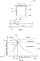
- Figure 1 is a schematic illustration of an embodiment of an article 100 comprising an overlay metal-based coating 104 overlaid on a metal-based substrate 102.
- the metal-based substrate 102 includes a nickel-based, cobalt-based, iron-based alloy, or a combination including any one or more of these. Examples of alloys include Alloy 718, Alloy 706, Alloy 725, RENE 88DT, RENE 104, RENE 65, UDIMET 720.
- the overlay metal-based coating 104 is configured to protect the metal-based substrate 102 from the environment.
- the overlay metal-based coating 104 may include a compound or a nickel-based, cobalt-base, or iron-based alloy.
- the overlay metal-based coating 104 comprises an alloy such as Alloy 625, Haynes 282, Alloy 718, GT33, and/or other suitable compositions.
- the overlay metal-based coating 104 and the metal-based substrate 102 meet at an interface 106.
- Figure 1 further illustrates a crack 108 disposed within the overlay metal-based coating 104.
- the range of interface toughness is configured such that responsive to the crack 108 initiated within the overlay metal-based coating, the crack has a propagation path 110 that is more energetically favorable along the interface 106 interposed between the metal-based substrate 102 and the overlay metal-based coating 104 as compared to through the interface into the metal-based substrate 102.
- the overlay metal-based coating 104 may be applied to the metal-based substrate 102 via any of several methods including thermal spray, electroplating, chemical vapor deposition (CVD), physical vapor deposition (PVD), or slurry-based deposition techniques.
- CVD chemical vapor deposition
- PVD physical vapor deposition
- slurry-based deposition techniques The size, shape, and complexity of the metal-based substrate 102 will dictate which of the methods advantageously lends itself to a given application.
- processing variable or combination of variables may be controlled to affect the interface toughness between the overlay metal-based coating and metal-based substrate, and how to increase or decrease the toughness as needed to implement the techniques disclosed herein.
- the metal-based coating 104 is deposited via a high velocity air fuel (HVAF) thermal spray process.
- HVAF processes encompass all appropriate manners of providing feedstock to an HVAF spray gun, such as by entraining feedstock powder in a flowing fluid such as gas or liquid.
- Many parameters can be controlled in this process that affect the interface toughness, including air and fuel pressures, powder size and feed rate, nozzle geometry, and/or the like.
- the interface toughness can be tailored by carefully controlling the distance between the end of the spray gun nozzle and the surface of the substrate material (i.e. the stand-off distance (SOD)). For instance, generally the SOD is inversely proportional to the interfacial toughness for the resultant coating.
- SOD stand-off distance
- the metal-based substrate may be advantageous to first coat the metal-based substrate with an intermediate coating that either strongly adheres, or has an intrinsically low material toughness relative to the substrate 102, thus making a compound substrate (metal-based substrate plus the intermediate coating).
- the intermediate coating may comprise a nickel-based, cobalt-based, or iron-based compound or alloy and may rely on interdiffusion with the metal-based substrate for adherence.
- Another material selection alternative includes a ceramic-based material having less than 50 atomic percent of metallic elements. The overlay metal-based coating 104 is then applied over this compound substrate.
- the metal-based substrate 102 or a compound substrate surface of the metal-based substrate 102 may be altered to provide an acceptable range of interface toughness between the overlay metal-based coating 104 and the metal-based substrate 102 and/or the compound substrate surface.
- the surface, prior to deposition of overlay coating 104 may be modified by blasting with an abrasive material such as sand, ceramic media, glass beads, ice, or metal shot; by acid etching, by anodizing, or by peening.
- the interface toughness is controlled directly by these surface treatment steps (for example, grit blasting aggressively to increase toughness, or lightly to decrease it).
- Figure 2 is a graphical illustration 200 of an embodiment of a range of interface toughness 202 based on fatigue and adhesion requirements 204 and 206, respectively.
- the fatigue requirement 204 may represent a low cycle fatigue requirement.
- Low cycle fatigue represents the cyclic loading of a material under high stress where an elastic limit is exceeded and the material undergoes plastic strain.
- low cycle fatigue can be described by the Coffin-Manson relationship where a number of cycles to failure is directly related to the plastic strain amplitude experience by the material. Additional discussion of low cycle fatigue is described in Dieter, George E., "Mechanical Metallurgy", 3rd Edition, McGraw-Hill, 1986 .
- the low cycle fatigue requirement may be based on bare metal performance of the metal-based substrate (e.g., similar to and/or the same as the metal-based substrate 102).
- the low cycle fatigue requirement may be set such that the overlay metal-based coating (e.g., similar to and/or the same as the overlay metal-based coating 104) is configured not to debit a non-coated metal-based substrate by more than a certain percentage.
- the set percentage can be based on an application requirement of the metal-based substrate.
- the metal-based substrate may be utilized in a jet engine or gas turbine with certain fatigue requirements.
- the set percentage of the low cycle fatigue can be zero percent, such that the overlay metal-based coating causes no debit to the operable life of the non-coated metal-based substrate.
- the set percentage of the low cycle fatigue may be twenty percent, such that the overlay metal-based coating debits an operable life of the non-coated metal-based substrate by twenty percent.
- the fatigue requirement 204 is positioned along a vertical axis 210 representing the required fatigue life of a system (e.g., jet engine or gas turbine).
- the fatigue life represents a minimum number of cycles and/or operating life of the component based on the application.
- the application of the metal-based substrate may be a part of equipment, such as an engine.
- the fatigue life of the metal-based substrate may represent a number of duty cycles of the engine during operational use prior to needing repair and/or operational failure.
- the fatigue requirement 204 is shown relative to a fatigue life curve 214 for the article 100 of Figure 1 .
- the fatigue life curve 214 is the projected fatigue life of the overlay metal-based coating/metal-based substrate system based on the interface toughness along a horizontal axis 208 that represents different interface toughnesses.
- the fatigue life curve 214 may be based on prior experimental information or model calculations.
- the fatigue life curve 214 illustrates an inverse relationship with the interface toughness. For example, as the interface toughness increases, the fatigue life curve 214 decreases.
- a lower interface toughness increases fatigue life as cracks propagating through the overlay metal-based coating are deflected at the interface between the coating and metal-based substrate and prevented from propagating into the metal-based substrate.
- the adhesion requirement 206 represents a minimum number of cycles required for the overlay metal-based coating to adhere to the metal-based substrate.
- the adhesion requirement 206 is shown relative to an adhesion curve 212 of the overlay metal-based coating.
- the adhesion curve 212 may be based on prior experimental information or model calculations.
- the adhesion curve 212 is the projected adhesion of the overlay metal-based coating based on the interface toughness.
- the adhesion curve 212 illustrates a direct relationship between adhesion of the overlay metal-based coating and interface toughness; as interface toughness increases, adhesion also increases.
- a range of interface toughness 202 for the overlay metal-based coating is based on the fatigue life and adhesion curves 214 and 212.
- portions 216 and 217 of the fatigue life and adhesion curves 214 and 212, respectively, are concurrently above the fatigue and adhesion requirements 204 and 206.
- the portions 216 and 217 define boundaries 220 and 222 of the range of interface toughness 202 in accordance with embodiments described herein.
- the range of interface toughness 202 is configured such that responsive to a crack initiated within the overlay metal-based coating, the crack has a propagation path that is more energetically favorable along the interface interposed between the metal-based substrate and the overlay metal-based coating as compared to a path through the interface into the metal-based substrate.
- the term energetically favorable is indicative of a direction and/or path based on the energy required to incrementally propagate a crack through a material. Cracks will predominantly move or propagate along the lowest possible energy path.
- the range of interface toughness 202 can be defined for the limiting fatigue requirement based on the metal-based substrate fatigue crack growth threshold stress intensity (e.g., ⁇ K th ).
- This threshold stress intensity e.g., ⁇ K th
- a crack within the overlay metal-based coating can extend or be transmitted past or through the interface into the metal-based substrate and continue propagating.
- the metal-based substrate fatigue crack growth threshold is based on one or more characteristics, such as the composition of the metal-based substrate and how it is processed, and is easily measured and well understood by those skilled in the art.
- the range of interface toughness 202 is configured to be less than some fraction of the metal-based substrate fatigue crack growth threshold, such that the propagation path of the crack is more energetically favorable to extend along the interface rather than through the interface into the metal-based substrate.
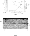
- Figure 3 illustrates a graphical illustration 300 of an embodiment that represents both interface toughness curve 308 and fatigue life 310 as a function of the stand-off distance (SOD) 302 used in a high velocity air fuel (HVAF) coating process.
- SOD stand-off distance
- HVAF high velocity air fuel
- the SOD is the physical distance, measured here in centimeters, between the end of the nozzle on the HVAF spray gun and the surface of the metal-based substrate.
- the overlay metal-based coating material was a standard bond coat composition containing cobalt, nickel, chromium, aluminum, and yttrium
- the metal-based substrate was a nickel-based alloy.
- the interface toughness curve 308 corresponds to the left vertical axis 304, while the fatigue life curve 310 corresponds to a Fatigue Z Score axis 306.
- the Fatigue Z Score axis 306 represents fatigue life as a Z score. The Z score quantifies fatigue life relative to a bare and/or uncoated metal-based substrate as the number of standard deviations from average.
- a negative value of the fatigue life curve 310 indicates a debit of the fatigue life of the overlay metal-based coating/metal-based substrate system. For example, a fatigue debit of approximately -3 standard deviations occurred in this particular case when the interface toughness was approximately 1.1 MPa m . This interface toughness represents approximately one-quarter of the metal-based substrate fatigue crack growth threshold (e.g., ⁇ K th ). This value, either directly measured or defined relative to substrate fatigue crack growth threshold, can be set as an upper bound of allowable interface toughness depending on the particular fatigue requirements of the application.
- a minimum interface toughness is at least about 0.05 MPa m to satisfy the adhesion requirement 206 (as shown in Figure 2 ).
- the lower bound is in a lower bound range from about 0.05 MPa m to about 0.2 MPa m .
- the upper bound is in an upper bound range from about 0.2 * ⁇ K th MPa m to about 0.5* ⁇ K th MPa m , where ⁇ K th is the fatigue crack growth threshold stress intensity of the substrate.
- An interface toughness in such a range can then meet the performance criteria for both the fatigue and adhesion requirements 204 and 206, which in this case sets the SOD of the HVAF spray gun to be between about 17 and 32 cm (e.g., it may be noted that 32 cm was the highest SOD studied here). More generally, the interface toughness may be represented as a range.
- the lower bound is set as an absolute toughness
- the upper bound of the range is specified as a fraction of the metal-based substrate fatigue crack growth threshold value.
- the lower bound of the range is specified to satisfy the adhesion requirement 206 for the article 100.
- the lower bound of the range is at least about 0.05 MPa m ; in some embodiments, such as where comparatively higher adhesion of the coating is deemed to be desirable, the lower bound may be set higher, such as at least about 0.1 MPa m . In one embodiment, the lower bound is 0.2 MPa m .
- the upper bound of the range is specified to satisfy the particular fatigue requirements of the application.
- the upper bound of the range is less than about 0.5 * ⁇ K th MPa m .
- the upper bound of the range can be 0.25 * ⁇ K th MPa m in one embodiment.
- the upper bound may be set to a lower value, such as, for example, less than about 0.25 * ⁇ K th MPa m and/or less than about 0.2* ⁇ K th MPa m .
- the upper bound is 0.2 * ⁇ K th MPa m .
- the actual range specified for a particular embodiment may be any combination of the upper and lower bounds described above.
- the interface toughness may be in a range from at least about 0.05 MPa m to less than about 0.5 * ⁇ K th MPa m . In another example, the interface toughness may be in a range from at least about 0.1 MPa m to less than about 0.25 * ⁇ K th MPa m . In another example, the interface toughness may be in a range from at least about 0.1 MPa m to less than about 0.2 * ⁇ K th MPa m . It may be noted that other combination of lower and upper bounds can be utilized as noted above.
- the interface toughness curve 308 was formed based on experimental data from overlay metal-based coatings 406 as shown in Figure 4 , applied at various SODs on metal-based substrates.
- the interface toughness was measured by applying an indenter directly on the interface between the overlay metal-based coating and metal based substrate under precisely controlled load. Under sufficient load, a crack 408 is formed along the interface due to the impression of the indenter 404. The length of the crack 402 due to indentation at a given load was measured and a procedure outlined in G.R.
- the fatigue life curve 310 in Figure 3 was formed based on mechanical testing where metal-based substrate test bars were coated with the overlay metal-based coating at various SODs and tested under conditions to simulate the fatigue experienced by a certain component in service. The coated test bars were cycled until failure, and the total number of cycles to failure was compared to that for an uncoated test bar to determine the Fatigue Z score axis 306 in Figure 3 .
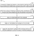
- Figure 5 illustrates a flow chart of an embodiment of a method 500 for applying an overlay metal-based coating at the range of interface toughness to the metal-based substrate.
- the method 500 may employ structures or aspects of various embodiments (e.g., systems and/or methods) discussed herein.
- certain steps (or operations) may be omitted or added, certain steps may be combined, certain steps may be performed simultaneously, certain steps may be performed concurrently, certain steps may be split into multiple steps, certain steps may be performed in a different order, or certain steps or series of steps may be re-performed in an iterative fashion.
- portions, aspects, and/or variations of the method 500 may be used as one or more algorithms to direct hardware to perform one or more operations described herein.
- a fatigue requirement 204 ( Figure 2 ) and adhesion requirement 206 are determined.
- the fatigue requirement 204 may represent a low cycle fatigue requirement representing the cyclic loading of a material under high stress where an elastic limit is exceeded and the material undergoes plastic strain.
- the adhesion requirement 206 may represent a minimum number of cycles required for the overlay metal-based coating to adhere to the metal-based substrate.
- the adhesion requirement 206 is based on characteristics and/or prior information of the metal-based substrate and/or the overlay metal-based coating.
- the range of interface toughness 202 of the metal-based coating based on the fatigue requirement 204 and the adhesion requirement 202 is determined.
- the range of interface toughness 202 for the overlay metal-based coating is based on the fatigue and adhesion curves 214 and 212.
- the range of interface toughness 202 is configured such that a crack initiated within the overlay metal-based coating has a propagation path that is more energetically favorable along the interface interposed between the metal-based substrate and the overlay metal-based coating as compared to a path through the interface into the metal-based substrate.
- a pre-coating treatment is applied to the surface treatment to the metal-based substrate.
- the metal-based substrate 102 or a compound substrate surface of the metal-based substrate 102 may be altered to provide an acceptable range of interface toughness between the overlay metal-based coating 104 and the metal-based substrate 102 and/or the compound substrate surface as is known in the art.
- an intermediate bonding layer is applied to the metal-based substrate 102 onto which the overlay metal-based coating 104 will be applied.
- the overlay metal-based coating 104 is applied on the metal-based substrate 102 such that the interface toughness is within the range of interface toughness 202.
- the HVAF spray gun as known in the art applies the overlay metal-based coating 104 at the SOD as shown in Figure 3 .
- an angle of the HVAF spray gun and/or temperature of the overlay metal-based coating 104 when emitted from the HVAF spray gun is utilized to increase or decrease the interface toughness of the overlay metal-based coating 104.
- the overlay metal-based coating can be applied in alternative processes as is known in the art, such as other thermal spray processes, cold spray, electroplating, physical vapor deposition, chemical vapor deposition, a slurry-based method, and/or the like.
- an article in an embodiment, includes a metal-based substrate having an overlay metal-based coating disposed on the substrate at an interface.
- the interface is configured such that a crack formed within the overlay metal-based coating and approaching the interface has a propagation path that is more energetically favorable along the interface than through the interface and into the metal-based substrate.
- the interface toughness is selected to have a toughness with a lower bound of at least about 0.05 MPa m and an upper bound of less than about 0.5* ⁇ K th MPa m .
- the interface toughness is selected to have a toughness with a lower bound of at least about 0.1 MPa m and an upper bound of less than about 0.2* ⁇ K th MPa m .
- the interface toughness is selected to have a toughness with a lower bound of at least about 0.05 * ⁇ K th MPa m to at least about 0.2 MPa m , and an upper bound from about 0.2 * ⁇ K th MPa m to about 0.5 * ⁇ K th MPa m .
- the upper bound is 0.25 * ⁇ K th MPa m and, in another embodiment, the upper bound is 0.2 * ⁇ K th MPa m .
- the lower bound can be 0.2 MPa m in one embodiment.
- the overlay metal-based coating comprises a nickel-based alloy, a cobalt-based alloy, an iron-based alloy, or any combination including one or more of these.
- the metal-based substrate comprises a nickel-based alloy, a cobalt-based alloy, an iron-based alloy, or a combination including one or more of these.
- an intermediate bonding layer is interposed between the metal-based substrate and the overlay metal-based coating. The intermediate bonding layer is configured such that a crack formed within the overlay metal-based coating and approaching the intermediate bonding layer has a propagation path that is more energetically favorable along the intermediate bonding layer than through the interface and into the metal-based substrate.
- a method in an embodiment, includes applying an overlay metal-based coating on a metal-based substrate.
- the interface between the overlay metal-based coating and metal-based substrate is configured such that a crack formed within the overlay metal-based coating and approaching the interface has a propagation path that is more energetically favorable along the interface than through the interface into the metal-based substrate.
- the overlay metal-based coating is at least one of a nickel-based, cobalt-based, or iron-based alloy, such as Alloy 625, Haynes 282, Alloy 718, or GT33
- the metal-based substrate is at least one of a nickel-based, cobalt-based, or iron-based alloy, such as Alloy 718, Alloy 706, R88DT, R104, R65, or U720.
- the interface between the overlay metal-based coating and the metal-based substrate has an interface toughness in a range from 0.05 MPa m to 0.5 * ⁇ Kth MPa m .
- applying the metal-based overlay coating comprises using a thermal spray process, cold spray, electroplating, physical vapor deposition, chemical vapor deposition, or a slurry-based method. Additionally or alternatively, the method includes applying a pre-coating surface treatment on the metal-based substrate. Additionally or alternatively, the method includes applying an intermediate bonding layer to the metal-based substrate.
- a method in an embodiment, includes applying an overlay metal-based coating on a metal-based substrate via a thermal spray process.
- the interface between the overlay metal-based coating and metal-based substrate is configured such that a crack formed within the overlay metal-based coating and approaching the interface has a propagation path that is more energetically favorable along the interface than through the interface into the metal-based substrate.
- the overlay metal-based coating comprises a nickel-based alloy, a cobalt-based alloy, or any combination including one or more of these.
- the metal-based substrate comprises a nickel-based alloy.
- the interface between the overlay metal-based coating and the metal-based substrate has an interface toughness in a range from 0.1 MPa m to 0.2* ⁇ K th (MPa m ) .
Landscapes
- Chemical & Material Sciences (AREA)
- Engineering & Computer Science (AREA)
- Materials Engineering (AREA)
- Organic Chemistry (AREA)
- Mechanical Engineering (AREA)
- Metallurgy (AREA)
- Chemical Kinetics & Catalysis (AREA)
- Plasma & Fusion (AREA)
- Physics & Mathematics (AREA)
- Wood Science & Technology (AREA)
- Inorganic Chemistry (AREA)
- Life Sciences & Earth Sciences (AREA)
- Composite Materials (AREA)
- Other Surface Treatments For Metallic Materials (AREA)
- Laminated Bodies (AREA)
- Turbine Rotor Nozzle Sealing (AREA)
Abstract
Description
- The subject matter described herein relates to applying an overlay metal-based coating to a metal-based substrate.
- Fatigue of a substrate, such as metal, can be accelerated in environments where oxidation and/or corrosion occur. Coatings are commonly used to protect the substrate from such environments. Conventionally, a coating process is designed to maximize the adhesion strength of the coating to the substrate, as a lack of sufficient adhesion results in the coating separating from the substrate during operation. However, excessive adhesion of the coating to the substrate can create an unacceptable debit in the fatigue performance of the substrate material.
- In an embodiment, an article is provided. The article includes a metal-based substrate having an overlay metal-based coating disposed on the substrate at an interface. The interface is configured such that a crack formed within the overlay metal-based coating and approaching the interface has a propagation path that is more energetically favorable along the interface than through the interface into the metal-based substrate.
- In an embodiment, a method is provided. The method includes applying an overlay metal-based coating on a metal-based substrate. The interface between the overlay metal-based coating and metal-based substrate is configured such that a crack formed within the overlay metal-based coating and approaching the interface has a propagation path that is more energetically favorable along the interface than through the interface into the metal-based substrate. In some embodiments, the overlay metal-based coating includes a nickel-based, cobalt-based, or iron-based alloy, or any combination including one or more of these. The metal-based substrate, in some embodiments, includes a nickel-based, cobalt-based, iron-based alloy, or a combination including one or more of these. In certain embodiments, the interface between the overlay metal-based coating and the metal-based substrate has an interface toughness in a range from 0.05 to

- In an embodiment, a method is provided. The method includes applying an overlay metal-based coating on a metal-based substrate using a thermal spray of a high velocity air fuel (HVAF) spray gun. The overlay metal-based coating including a nickel-based alloy, a cobalt-based alloy, or any combination including one or more of these. The metal-based substrate including a nickel-based alloy. The interface toughness between the overlay metal-based coating and the metal-based substrate has a lower bound of 0.1


- In an embodiment, an article is provided comprising: an overlay metal-based coating on a metal-based substrate, the overlay metal-based coating including a nickel-based alloy, a cobalt-based alloy, or any combination including one or more of these, the metal-based substrate including a nickel-based alloy, wherein the interface toughness between the overlay metal-based coating and the metal-based substrate is selected to have a lower bound of


- The present inventive subject matter will be better understood from reading the following description of non-limiting embodiments, with reference to the attached drawings, wherein below:
-
Figure 1 is a schematic illustration of an embodiment of an overlay metal-based coating on a metal-based substrate; -
Figure 2 is a graphical illustration of an embodiment of a range of interface toughness and related fatigue and adhesion requirements and performance; -
Figure 3 is a graphical illustration of an embodiment of a stand-off distance and its relationship with an interface toughness and fatigue life; -
Figure 4 illustrates a crack of an embodiment for an overlay metal-based coating formed from an indenter. -
Figure 5 illustrates a flow chart of an embodiment of a method for applying an overlay metal-based coating at a desired interface toughness to a substrate. - Embodiments of the subject matter described herein provide systems and methods for applying an overlay metal-based coating to a metal-based substrate. The embodiments describe an approach where the interface toughness between an overlay metal-based coating and a metal-based substrate is balanced to provide both acceptable coating adhesion and fatigue performance of the system. Achieving a balance of coating adhesion and substrate fatigue performance is based on the range of coating/substrate interface toughness values. An overlay metal-based coating is a coating that depends primarily on mechanical bonding to adhere to the substrate, as opposed to metallurgical bonding such as is achieved through interdiffusion. Overlay coatings exhibit no significant diffusion of elements from the coating into the substrate, or elements from the substrate into the coating, during the deposition process. A metal-based substrate is the component that will be coated and that carries the structural load. For both the coating and substrate, the term "metal-based" as used herein means the referenced coating or substrate has a metallic character and includes more than 50 atomic percent metal elements. In one embodiment, the interface referred to herein is the surface or plane at which the overlay metal-based coating and metal-based substrate meet. In a second embodiment, the interface is defined as an additional layer of material added between the overlay metal-based coating and metal-based substrate with an upper limit defined by the surface or plane at which the metal-based coating meets the added layer and a lower limit defined by the surface or plane at which the metal-based substrate meets the added layer. The fatigue requirement can represent a number of cycles and/or required operable life of the metal-based substrate. The number of cycles can represent a number of revolutions and/or duty cycles experienced by the metal-based substrate. Additionally or alternatively, the fatigue requirement represents the operable life of equipment that includes the metal-based substrate, such as an engine, prior to failure or when repair conditions are expected and/or required to be needed.
- The adhesion requirement is typically a specification of the adhesion strength of the coating to the substrate that is based on a service life of the overlay metal-based coating to be adhered to the surface of the metal-based substrate. The adhesion requirement is specified to provide a minimum amount of time for the overlay metal-based coating to adhere to the metal-based substrate and/or to provide a barrier to protect the metal-based substrate from environmental conditions. For example, the adhesion requirement is selected such that the overlay metal-based coating adheres to the metal-based substrate for the operable life of the metal-based substrate.
- Over time, cracks can form and propagate through an overlay metal-based coating/metal-based substrate system in three stages: (1) overlay metal-based coating crack initiation, (2) crack propagation through the overlay metal-based coating, and (3) deflection at, or propagation through, the overlay metal-based coating/metal-based substrate interface. The time required for the first and second stages is highly dependent on service conditions experienced by the metal-based substrate and the environment.
- During operation, one or more cracks may propagate through a thickness of the overlay metal-based coating, at which point any further crack propagation is considered to be in stage three. In one embodiment, the interface represents the position where the overlay metal-based coating and the metal-based substrate meet. For example, the interface can be referred to as the bottom of the overlaid metal-based coating, or the top of the metal-based substrate. The shape of the interface is based on the shape of the metal-based substrate. For example, the interface may represent a planar surface, a linear surface, a round surface, and/or the like. In one embodiment, the metal-based substrate is an uncoated material, that is, there is no other layer interposed between the substrate and the overlay coating. In an alternative embodiment a layer of material (referred to herein as "the intermediate layer") is disposed between the overlay coating and the substrate. In this embodiment, the interface is defined to include (a) the intermediate layer of material, (b) the surface or plane at which the overlay coating meets the intermediate layer, and (c) the surface or plane at which the substrate meets the intermediate layer. Thus, in this embodiment, a crack is considered to be present at the interface if its tip is positioned in any of (a), (b), or (c) described above.
- During stage three, a crack that has traveled through an overlay metal-based coating and arrived at the interface, as that term is defined above, can either propagate across the interface into the metal-based substrate or deflect along the interface. The path the crack takes is based on the interface toughness of the overlay metal-based coating/metal-based substrate article. When the interface toughness is bounded by the fatigue and adhesion requirements in accordance with embodiments described herein, the crack is deflected along the interface rather than through or across the interface into the substrate material. As a result, the crack in the overlay metal-based coating extends or propagates along the interface, which does not result in a fatigue life debit of the metal-based substrate. Alternatively, when the interface toughness exceeds the fatigue and adhesion requirements the crack can undesirably propagate across the interface, because crack propagation in this situation favors travel through the substrate material relative to travel through the interface. If enough cracks are transmitted into the substrate early in life, a fatigue debit of the underlying substrate may result, resulting in, for instance, a shortening of the life of the component due to fatigue failure. For very low interface toughness values, the adhesion of the overlay metal-based coating to the metal-based substrate is also decreased. Due to this low adhesion, the overlay metal-based coating can liberate during operation, leaving one or more portions of the metal-based substrate exposed to the environment. The exposed portions of the metal-based substrate may crack early because they are exposed to the environment and lack the protection of the overlay metal-based coating. These early cracks could also lead to a debit in fatigue life.
- The embodiments described herein determine a range of required interface toughness associated with a balance of fatigue life and adhesion of the overlay metal-based coating to the metal-based substrate based on a fatigue requirement and adhesion requirement. The range of interface toughness enables the overlay metal-based coating to work in balance with the metal-based substrate to provide protection from the environment and concurrently cause no, or limited, intrinsic performance debit of the metal-based substrate. The protection of the metal-based substrate by the overlay metal-based coating increases the operating life of the overlay metal-based coating/metal-based substrate article relative to an uncoated substrate operating in a similar environment. For example, the metal-based substrate may be a part of an engine (e.g., jet engine) or a gas turbine. While the description herein may focus on the jet engine or gas turbine, not all embodiments are limited to engines and turbines, and the overlay metal-based coatings for substrates of other types of equipment may be applied using the systems and methods described herein.
-
Figure 1 is a schematic illustration of an embodiment of anarticle 100 comprising an overlay metal-basedcoating 104 overlaid on a metal-basedsubstrate 102. The metal-basedsubstrate 102 includes a nickel-based, cobalt-based, iron-based alloy, or a combination including any one or more of these. Examples of alloys include Alloy 718, Alloy 706, Alloy 725, RENE 88DT,RENE 104, RENE 65, UDIMET 720. The overlay metal-basedcoating 104 is configured to protect the metal-basedsubstrate 102 from the environment. The overlay metal-basedcoating 104 may include a compound or a nickel-based, cobalt-base, or iron-based alloy. For example, in some embodiments the overlay metal-basedcoating 104 comprises an alloy such as Alloy 625, Haynes 282, Alloy 718, GT33, and/or other suitable compositions. The overlay metal-basedcoating 104 and the metal-basedsubstrate 102 meet at aninterface 106. -
Figure 1 further illustrates acrack 108 disposed within the overlay metal-basedcoating 104. As further described herein, the range of interface toughness is configured such that responsive to thecrack 108 initiated within the overlay metal-based coating, the crack has apropagation path 110 that is more energetically favorable along theinterface 106 interposed between the metal-basedsubstrate 102 and the overlay metal-basedcoating 104 as compared to through the interface into the metal-basedsubstrate 102. - The overlay metal-based
coating 104 may be applied to the metal-basedsubstrate 102 via any of several methods including thermal spray, electroplating, chemical vapor deposition (CVD), physical vapor deposition (PVD), or slurry-based deposition techniques. The size, shape, and complexity of the metal-basedsubstrate 102 will dictate which of the methods advantageously lends itself to a given application. One skilled in the art for each process, when given to understand the disclosure herein, will understand what processing variable or combination of variables may be controlled to affect the interface toughness between the overlay metal-based coating and metal-based substrate, and how to increase or decrease the toughness as needed to implement the techniques disclosed herein. - In an embodiment, the metal-based
coating 104 is deposited via a high velocity air fuel (HVAF) thermal spray process. HVAF processes encompass all appropriate manners of providing feedstock to an HVAF spray gun, such as by entraining feedstock powder in a flowing fluid such as gas or liquid. Many parameters can be controlled in this process that affect the interface toughness, including air and fuel pressures, powder size and feed rate, nozzle geometry, and/or the like. As a particular example, the interface toughness can be tailored by carefully controlling the distance between the end of the spray gun nozzle and the surface of the substrate material (i.e. the stand-off distance (SOD)). For instance, generally the SOD is inversely proportional to the interfacial toughness for the resultant coating. - In another embodiment, it is difficult to achieve the required interface toughness range for an interface formed directly between the overlay metal-based
coating 104 and the bare metal-basedsubstrate 102. In this case, it may be advantageous to first coat the metal-based substrate with an intermediate coating that either strongly adheres, or has an intrinsically low material toughness relative to thesubstrate 102, thus making a compound substrate (metal-based substrate plus the intermediate coating). The intermediate coating may comprise a nickel-based, cobalt-based, or iron-based compound or alloy and may rely on interdiffusion with the metal-based substrate for adherence. Another material selection alternative includes a ceramic-based material having less than 50 atomic percent of metallic elements. The overlay metal-basedcoating 104 is then applied over this compound substrate. - In another embodiment, the metal-based
substrate 102 or a compound substrate surface of the metal-basedsubstrate 102 may be altered to provide an acceptable range of interface toughness between the overlay metal-basedcoating 104 and the metal-basedsubstrate 102 and/or the compound substrate surface. The surface, prior to deposition ofoverlay coating 104, may be modified by blasting with an abrasive material such as sand, ceramic media, glass beads, ice, or metal shot; by acid etching, by anodizing, or by peening. In one embodiment, the interface toughness is controlled directly by these surface treatment steps (for example, grit blasting aggressively to increase toughness, or lightly to decrease it). -
Figure 2 is agraphical illustration 200 of an embodiment of a range ofinterface toughness 202 based on fatigue andadhesion requirements - The
fatigue requirement 204 may represent a low cycle fatigue requirement. Low cycle fatigue represents the cyclic loading of a material under high stress where an elastic limit is exceeded and the material undergoes plastic strain. For example, low cycle fatigue can be described by the Coffin-Manson relationship where a number of cycles to failure is directly related to the plastic strain amplitude experience by the material. Additional discussion of low cycle fatigue is described in Dieter, George E., "Mechanical Metallurgy", 3rd Edition, McGraw-Hill, 1986. - Additionally or alternatively, the low cycle fatigue requirement may be based on bare metal performance of the metal-based substrate (e.g., similar to and/or the same as the metal-based substrate 102). For example, the low cycle fatigue requirement may be set such that the overlay metal-based coating (e.g., similar to and/or the same as the overlay metal-based coating 104) is configured not to debit a non-coated metal-based substrate by more than a certain percentage. The set percentage can be based on an application requirement of the metal-based substrate. For example, the metal-based substrate may be utilized in a jet engine or gas turbine with certain fatigue requirements. The set percentage of the low cycle fatigue can be zero percent, such that the overlay metal-based coating causes no debit to the operable life of the non-coated metal-based substrate. In another example, the set percentage of the low cycle fatigue may be twenty percent, such that the overlay metal-based coating debits an operable life of the non-coated metal-based substrate by twenty percent.
- The
fatigue requirement 204 is positioned along avertical axis 210 representing the required fatigue life of a system (e.g., jet engine or gas turbine). The fatigue life represents a minimum number of cycles and/or operating life of the component based on the application. For example, the application of the metal-based substrate may be a part of equipment, such as an engine. The fatigue life of the metal-based substrate may represent a number of duty cycles of the engine during operational use prior to needing repair and/or operational failure. - The
fatigue requirement 204 is shown relative to afatigue life curve 214 for thearticle 100 ofFigure 1 . Thefatigue life curve 214 is the projected fatigue life of the overlay metal-based coating/metal-based substrate system based on the interface toughness along ahorizontal axis 208 that represents different interface toughnesses. Thefatigue life curve 214 may be based on prior experimental information or model calculations. Thefatigue life curve 214 illustrates an inverse relationship with the interface toughness. For example, as the interface toughness increases, thefatigue life curve 214 decreases. - Additionally or alternatively, a lower interface toughness increases fatigue life as cracks propagating through the overlay metal-based coating are deflected at the interface between the coating and metal-based substrate and prevented from propagating into the metal-based substrate.
- The
adhesion requirement 206 represents a minimum number of cycles required for the overlay metal-based coating to adhere to the metal-based substrate. Theadhesion requirement 206 is shown relative to anadhesion curve 212 of the overlay metal-based coating. Theadhesion curve 212 may be based on prior experimental information or model calculations. Theadhesion curve 212 is the projected adhesion of the overlay metal-based coating based on the interface toughness. Theadhesion curve 212 illustrates a direct relationship between adhesion of the overlay metal-based coating and interface toughness; as interface toughness increases, adhesion also increases. - A range of
interface toughness 202 for the overlay metal-based coating is based on the fatigue life andadhesion curves portions adhesion curves adhesion requirements portions boundaries interface toughness 202 in accordance with embodiments described herein. The range ofinterface toughness 202 is configured such that responsive to a crack initiated within the overlay metal-based coating, the crack has a propagation path that is more energetically favorable along the interface interposed between the metal-based substrate and the overlay metal-based coating as compared to a path through the interface into the metal-based substrate. The term energetically favorable is indicative of a direction and/or path based on the energy required to incrementally propagate a crack through a material. Cracks will predominantly move or propagate along the lowest possible energy path. The range ofinterface toughness 202 can be defined for the limiting fatigue requirement based on the metal-based substrate fatigue crack growth threshold stress intensity (e.g., ΔKth). This threshold stress intensity (e.g., ΔKth) represents a critical stress intensity, or energy, required to propagate a crack through the interface into the metal-based substrate. For example, when the interface toughness is greater than some fraction of the metal-based substrate fatigue crack growth threshold, a crack within the overlay metal-based coating can extend or be transmitted past or through the interface into the metal-based substrate and continue propagating. The metal-based substrate fatigue crack growth threshold is based on one or more characteristics, such as the composition of the metal-based substrate and how it is processed, and is easily measured and well understood by those skilled in the art. The range ofinterface toughness 202 is configured to be less than some fraction of the metal-based substrate fatigue crack growth threshold, such that the propagation path of the crack is more energetically favorable to extend along the interface rather than through the interface into the metal-based substrate. -
Figure 3 illustrates agraphical illustration 300 of an embodiment that represents bothinterface toughness curve 308 andfatigue life 310 as a function of the stand-off distance (SOD) 302 used in a high velocity air fuel (HVAF) coating process.Figure 3 illustrates an example of an embodiment described herein. - The SOD is the physical distance, measured here in centimeters, between the end of the nozzle on the HVAF spray gun and the surface of the metal-based substrate. In this example, the overlay metal-based coating material was a standard bond coat composition containing cobalt, nickel, chromium, aluminum, and yttrium, and the metal-based substrate was a nickel-based alloy. The
interface toughness curve 308 corresponds to the leftvertical axis 304, while thefatigue life curve 310 corresponds to a FatigueZ Score axis 306. The FatigueZ Score axis 306 represents fatigue life as a Z score. The Z score quantifies fatigue life relative to a bare and/or uncoated metal-based substrate as the number of standard deviations from average. A negative value of thefatigue life curve 310 indicates a debit of the fatigue life of the overlay metal-based coating/metal-based substrate system. For example, a fatigue debit of approximately -3 standard deviations occurred in this particular case when the interface toughness was approximately
- The interface toughness and fatigue life correlation and ranges, in this example as a function of SOD, was a surprising result because, based on conventional practice in the art, interface toughness is typically maximized for coating adhesion, and fatigue life is simply a net result of the process. Here, as shown in
Figure 3 , it is observed that fatigue life can be improved by incrementally reducing interface toughness so that an overlay metal-based coating/metal-based substrate article can be balanced for both acceptable fatigue and adhesion requirements. In one embodiment, a minimum interface toughness is at least about
Figure 2 ). Combined with the fatigue requirement discussed above, an interface toughness in a range defined by an upper bound and a lower bound. The lower bound is in a lower bound range from about


adhesion requirements adhesion requirement 206 for thearticle 100. In one embodiment, the lower bound of the range is at least about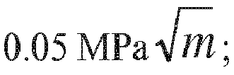


- The
interface toughness curve 308 was formed based on experimental data from overlay metal-basedcoatings 406 as shown inFigure 4 , applied at various SODs on metal-based substrates. The interface toughness was measured by applying an indenter directly on the interface between the overlay metal-based coating and metal based substrate under precisely controlled load. Under sufficient load, acrack 408 is formed along the interface due to the impression of theindenter 404. The length of thecrack 402 due to indentation at a given load was measured and a procedure outlined in G.R. Anstis, et al., "A Critical Evaluation of Indentation Techniques for Measuring Fracture Toughness: I, Direct Crack Measurements", Journal of the American Ceramic Society, v64, n9, p533-538, 1981, was followed to derive an interface toughness value. This measurement it repeated multiple times, on samples with varying SOD, to create theinterface toughness curve 308 shown inFigure 3 . - The
fatigue life curve 310 inFigure 3 was formed based on mechanical testing where metal-based substrate test bars were coated with the overlay metal-based coating at various SODs and tested under conditions to simulate the fatigue experienced by a certain component in service. The coated test bars were cycled until failure, and the total number of cycles to failure was compared to that for an uncoated test bar to determine the FatigueZ score axis 306 inFigure 3 . -
Figure 5 illustrates a flow chart of an embodiment of amethod 500 for applying an overlay metal-based coating at the range of interface toughness to the metal-based substrate. Themethod 500, for example, may employ structures or aspects of various embodiments (e.g., systems and/or methods) discussed herein. In various embodiments, certain steps (or operations) may be omitted or added, certain steps may be combined, certain steps may be performed simultaneously, certain steps may be performed concurrently, certain steps may be split into multiple steps, certain steps may be performed in a different order, or certain steps or series of steps may be re-performed in an iterative fashion. In various embodiments, portions, aspects, and/or variations of themethod 500 may be used as one or more algorithms to direct hardware to perform one or more operations described herein. - Beginning at 502, a fatigue requirement 204 (
Figure 2 ) andadhesion requirement 206 are determined. For example, thefatigue requirement 204 may represent a low cycle fatigue requirement representing the cyclic loading of a material under high stress where an elastic limit is exceeded and the material undergoes plastic strain. Theadhesion requirement 206 may represent a minimum number of cycles required for the overlay metal-based coating to adhere to the metal-based substrate. Optionally, theadhesion requirement 206 is based on characteristics and/or prior information of the metal-based substrate and/or the overlay metal-based coating. - At 504, the range of
interface toughness 202 of the metal-based coating based on thefatigue requirement 204 and theadhesion requirement 202 is determined. The range ofinterface toughness 202 for the overlay metal-based coating is based on the fatigue andadhesion curves interface toughness 202 is configured such that a crack initiated within the overlay metal-based coating has a propagation path that is more energetically favorable along the interface interposed between the metal-based substrate and the overlay metal-based coating as compared to a path through the interface into the metal-based substrate. - At 510, a pre-coating treatment is applied to the surface treatment to the metal-based substrate. For example, the metal-based
substrate 102 or a compound substrate surface of the metal-basedsubstrate 102 may be altered to provide an acceptable range of interface toughness between the overlay metal-basedcoating 104 and the metal-basedsubstrate 102 and/or the compound substrate surface as is known in the art. - At 512, an intermediate bonding layer is applied to the metal-based
substrate 102 onto which the overlay metal-basedcoating 104 will be applied. - At 514, the overlay metal-based
coating 104 is applied on the metal-basedsubstrate 102 such that the interface toughness is within the range ofinterface toughness 202. For example, the HVAF spray gun as known in the art applies the overlay metal-basedcoating 104 at the SOD as shown inFigure 3 . Additionally or alternatively, an angle of the HVAF spray gun and/or temperature of the overlay metal-basedcoating 104 when emitted from the HVAF spray gun is utilized to increase or decrease the interface toughness of the overlay metal-basedcoating 104. Additionally or alternatively, the overlay metal-based coating can be applied in alternative processes as is known in the art, such as other thermal spray processes, cold spray, electroplating, physical vapor deposition, chemical vapor deposition, a slurry-based method, and/or the like. - In an embodiment, an article is provided. The article includes a metal-based substrate having an overlay metal-based coating disposed on the substrate at an interface. The interface is configured such that a crack formed within the overlay metal-based coating and approaching the interface has a propagation path that is more energetically favorable along the interface than through the interface and into the metal-based substrate.
- Optionally, the interface toughness is selected to have a toughness with a lower bound of at least about


- Optionally, the overlay metal-based coating comprises a nickel-based alloy, a cobalt-based alloy, an iron-based alloy, or any combination including one or more of these. Optionally, the metal-based substrate comprises a nickel-based alloy, a cobalt-based alloy, an iron-based alloy, or a combination including one or more of these. Additionally or alternatively, an intermediate bonding layer is interposed between the metal-based substrate and the overlay metal-based coating. The intermediate bonding layer is configured such that a crack formed within the overlay metal-based coating and approaching the intermediate bonding layer has a propagation path that is more energetically favorable along the intermediate bonding layer than through the interface and into the metal-based substrate.
- In an embodiment, a method is provided. The method includes applying an overlay metal-based coating on a metal-based substrate. The interface between the overlay metal-based coating and metal-based substrate is configured such that a crack formed within the overlay metal-based coating and approaching the interface has a propagation path that is more energetically favorable along the interface than through the interface into the metal-based substrate. The overlay metal-based coating is at least one of a nickel-based, cobalt-based, or iron-based alloy, such as Alloy 625, Haynes 282, Alloy 718, or GT33, and the metal-based substrate is at least one of a nickel-based, cobalt-based, or iron-based alloy, such as Alloy 718, Alloy 706, R88DT, R104, R65, or U720. The interface between the overlay metal-based coating and the metal-based substrate has an interface toughness in a range from
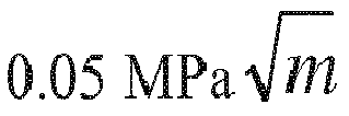

- Optionally, applying the metal-based overlay coating comprises using a thermal spray process, cold spray, electroplating, physical vapor deposition, chemical vapor deposition, or a slurry-based method. Additionally or alternatively, the method includes applying a pre-coating surface treatment on the metal-based substrate. Additionally or alternatively, the method includes applying an intermediate bonding layer to the metal-based substrate.
- In an embodiment, a method is provided. The method includes applying an overlay metal-based coating on a metal-based substrate via a thermal spray process. The interface between the overlay metal-based coating and metal-based substrate is configured such that a crack formed within the overlay metal-based coating and approaching the interface has a propagation path that is more energetically favorable along the interface than through the interface into the metal-based substrate. The overlay metal-based coating comprises a nickel-based alloy, a cobalt-based alloy, or any combination including one or more of these. The metal-based substrate comprises a nickel-based alloy. The interface between the overlay metal-based coating and the metal-based substrate has an interface toughness in a range from


- As used herein, an element or step recited in the singular and proceeded with the word "a" or "an" should be understood as not excluding plural of said elements or steps, unless such exclusion is explicitly stated. Furthermore, references to "one embodiment" of the presently described subject matter are not intended to be interpreted as excluding the existence of additional embodiments that also incorporate the recited features. Moreover, unless explicitly stated to the contrary, embodiments "comprising" or "having" an element or a plurality of elements having a particular property may include additional such elements not having that property.
- It is to be understood that the above description is intended to be illustrative, and not restrictive. For example, the above-described embodiments (and/or aspects thereof) may be used in combination with each other. In addition, many modifications may be made to adapt a particular situation or material to the teachings of the subject matter set forth herein without departing from its scope. While the dimensions and types of materials described herein are intended to define the parameters of the disclosed subject matter, they are by no means limiting and are exemplary embodiments. Many other embodiments will be apparent to those of skill in the art upon reviewing the above description. The scope of the subject matter described herein should, therefore, be determined with reference to the appended claims, along with the full scope of equivalents to which such claims are entitled. In the appended claims, the terms "including" and "in which" are used as the plain-English equivalents of the respective terms "comprising" and "wherein." Moreover, in the following claims, the terms "first," "second," and "third," etc. are used merely as labels, and are not intended to impose numerical requirements on their objects. Further, the limitations of the following claims are not written in means-plus-function format and are not intended to be interpreted based on 35 U.S.C. § 112(f), unless and until such claim limitations expressly use the phrase "means for" followed by a statement of function void of further structure.
- This written description uses examples to disclose several embodiments of the subject matter set forth herein, including the best mode, and also to enable a person of ordinary skill in the art to practice the embodiments of disclosed subject matter, including making and using the devices or systems and performing the methods. The patentable scope of the subject matter described herein is defined by the claims, and may include other examples that occur to those of ordinary skill in the art. Such other examples are intended to be within the scope of the claims if they have structural elements that do not differ from the literal language of the claims, or if they include equivalent structural elements with insubstantial differences from the literal languages of the claims.
Claims (14)
- An article (100), comprising:a metal-based substrate (102) having an overlay metal-based coating disposed on the substrate at an interface (106) having an interface toughness, wherein the interface is configured such that a crack formed within the overlay metal-based coating and approaching the interface (106) has a propagation path (110) that is more energetically favorable along the interface (106) than through the interface (106) and into the metal-based substrate (102).
- The article of claim 1, wherein the interface toughness (202) is at least about

- The article of claim 1 or 2, wherein the interface toughness (202) is less than about

- The article of claim 1, wherein the interface toughness (202) is in a range defined by an upper bound and a lower bound, wherein the lower bound is in a lower bound range from about

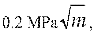


- The article of claim 4, wherein the upper bound is

- The article of claim 4, wherein the upper bound is

- The article of claim 4 or 5, wherein the lower bound is
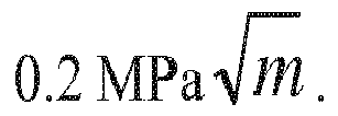
- The article (100) of any one of claims 1 to 7, wherein the overlay metal-based coating (104) comprises a nickel-based alloy, a cobalt-based alloy, an iron-based alloy, or any combination including one or more of these.
- The article (100) of any one of claims 1 to 8, wherein the metal-based substrate (102) comprises a nickel-based alloy, a cobalt-based alloy, an iron-based alloy, or a combination including one or more of these.
- The article (100) of any one of claims 1 to 9, wherein an intermediate bonding layer is interposed between the metal-based substrate (102) and the overlay metal-based coating (104), wherein the intermediate bonding layer is configured such that the crack (108) formed within the overlay metal-based coating (104) and approaching the intermediate bonding layer has a propagation path (110) that is more energetically favorable along the intermediate bonding layer than through the intermediate bonding layer and into the metal-based substrate (102).
- A method, comprising:applying an overlay metal-based coating on a metal-based substrate, wherein the interface between the overlay metal-based coating and metal-based substrate is configured such that a crack formed within the overlay metal-based coating and approaching the interface has a propagation path that is more energetically favorable along the interface than through the interface into the metal-based substrate, and wherein the overlay metal-based coating comprises a nickel-based alloy, a cobalt-based alloy, an iron-based alloy, or any combination including one or more of these wherein the metal-based substrate comprises a nickel-based alloy, a cobalt-based alloy, an iron-based alloy, or a combination including one or more of these, and wherein the interface between the overlay metal-based coating and the metal-based substrate has an interface toughness in a range from


- The method of claim 11, wherein applying the metal-based overlay coating comprises using a thermal spray process, cold spray, electroplating, physical vapor deposition, chemical vapor deposition, or a slurry-based method.
- The method of claim 11 or 12 further comprising applying a pre-coating surface treatment on the metal-based substrate.
- The method of any one of claims 11 to 13, further comprising applying an intermediate bonding layer to the metal-based substrate.
Applications Claiming Priority (1)
| Application Number | Priority Date | Filing Date | Title |
|---|---|---|---|
| US15/729,181 US10704133B2 (en) | 2017-10-10 | 2017-10-10 | Coated article and method for making |
Publications (2)
| Publication Number | Publication Date |
|---|---|
| EP3470224A1 true EP3470224A1 (en) | 2019-04-17 |
| EP3470224B1 EP3470224B1 (en) | 2021-04-28 |
Family
ID=63642819
Family Applications (1)
| Application Number | Title | Priority Date | Filing Date |
|---|---|---|---|
| EP18195399.3A Active EP3470224B1 (en) | 2017-10-10 | 2018-09-19 | Coated article and method for making |
Country Status (3)
| Country | Link |
|---|---|
| US (1) | US10704133B2 (en) |
| EP (1) | EP3470224B1 (en) |
| CN (1) | CN109652800B (en) |
Citations (7)
| Publication number | Priority date | Publication date | Assignee | Title |
|---|---|---|---|---|
| US6749951B1 (en) * | 2003-03-14 | 2004-06-15 | General Electric Company | Coated article having a quasicrystalline-ductile metal layered coating with high wear resistance, and its preparation and use |
| WO2004090288A2 (en) * | 2003-04-01 | 2004-10-21 | The Nanosteel Company | Controller thermal expansion of welds to enhance toughness |
| US20100151272A1 (en) * | 2006-02-06 | 2010-06-17 | Hamilton Sundstrand Corporation | Coating process for fatigue critical components |
| US20130177705A1 (en) * | 2012-01-05 | 2013-07-11 | General Electric Company | Applying bond coat using cold spraying processes and articles thereof |
| EP2781560A1 (en) * | 2013-03-18 | 2014-09-24 | General Electric Company | A bond coat system and a coated component |
| WO2014165073A1 (en) * | 2013-03-13 | 2014-10-09 | General Electric Company | Coatings for metallic substrates |
| EP3388559A1 (en) * | 2017-04-14 | 2018-10-17 | Hamilton Sundstrand Corporation | Corrosion and fatigue resistant coating for a non-line-of-sight (nlos) process |
Family Cites Families (12)
| Publication number | Priority date | Publication date | Assignee | Title |
|---|---|---|---|---|
| US3756159A (en) * | 1971-11-15 | 1973-09-04 | W Sternad | Railroad car handling and classification apparatus |
| US3846159A (en) * | 1972-08-18 | 1974-11-05 | United Aircraft Corp | Eutectic alloy coating |
| JP3302589B2 (en) | 1997-02-06 | 2002-07-15 | 株式会社日立製作所 | Ceramic coated gas turbine blade |
| JPH11311103A (en) | 1998-04-27 | 1999-11-09 | Toshiba Corp | High-temperature components, high-temperature components for gas turbines, and methods for producing them |
| JP4434444B2 (en) | 2000-07-14 | 2010-03-17 | Jsr株式会社 | Coating method with intermetallic compound |
| EP1411210A1 (en) | 2002-10-15 | 2004-04-21 | ALSTOM Technology Ltd | Method of depositing an oxidation and fatigue resistant MCrAIY-coating |
| US7563503B2 (en) | 2003-01-10 | 2009-07-21 | The University Of Connecticut | Coatings, materials, articles, and methods of making thereof |
| CA2582312C (en) | 2006-05-05 | 2014-05-13 | Sulzer Metco Ag | A method for the manufacture of a coating |
| US7740948B1 (en) * | 2006-05-31 | 2010-06-22 | The United States Of America As Represented By The United States Department Of Energy | Thermal barrier coatings |
| US9108276B2 (en) | 2008-05-16 | 2015-08-18 | Consolidated Nuclear Security, LLC | Hardface coating systems and methods for metal alloys and other materials for wear and corrosion resistant applications |
| US20130157078A1 (en) * | 2011-12-19 | 2013-06-20 | General Electric Company | Nickel-Cobalt-Based Alloy And Bond Coat And Bond Coated Articles Incorporating The Same |
| EP2853566B1 (en) | 2013-09-25 | 2017-07-26 | Crompton Technology Group Ltd. | Coated composites |
-
2017
- 2017-10-10 US US15/729,181 patent/US10704133B2/en not_active Expired - Fee Related
-
2018
- 2018-09-19 EP EP18195399.3A patent/EP3470224B1/en active Active
- 2018-10-09 CN CN201811173260.3A patent/CN109652800B/en not_active Expired - Fee Related
Patent Citations (7)
| Publication number | Priority date | Publication date | Assignee | Title |
|---|---|---|---|---|
| US6749951B1 (en) * | 2003-03-14 | 2004-06-15 | General Electric Company | Coated article having a quasicrystalline-ductile metal layered coating with high wear resistance, and its preparation and use |
| WO2004090288A2 (en) * | 2003-04-01 | 2004-10-21 | The Nanosteel Company | Controller thermal expansion of welds to enhance toughness |
| US20100151272A1 (en) * | 2006-02-06 | 2010-06-17 | Hamilton Sundstrand Corporation | Coating process for fatigue critical components |
| US20130177705A1 (en) * | 2012-01-05 | 2013-07-11 | General Electric Company | Applying bond coat using cold spraying processes and articles thereof |
| WO2014165073A1 (en) * | 2013-03-13 | 2014-10-09 | General Electric Company | Coatings for metallic substrates |
| EP2781560A1 (en) * | 2013-03-18 | 2014-09-24 | General Electric Company | A bond coat system and a coated component |
| EP3388559A1 (en) * | 2017-04-14 | 2018-10-17 | Hamilton Sundstrand Corporation | Corrosion and fatigue resistant coating for a non-line-of-sight (nlos) process |
Non-Patent Citations (1)
| Title |
|---|
| G.R. ANSTIS ET AL.: "A Critical Evaluation of Indentation Techniques for Measuring Fracture Toughness: I, Direct Crack Measurements", JOURNAL OF THE AMERICAN CERAMIC SOCIETY, vol. 64, no. 9, 1981, pages 533 - 538 |
Also Published As
| Publication number | Publication date |
|---|---|
| CN109652800A (en) | 2019-04-19 |
| EP3470224B1 (en) | 2021-04-28 |
| US20190106779A1 (en) | 2019-04-11 |
| CN109652800B (en) | 2022-02-22 |
| US10704133B2 (en) | 2020-07-07 |
Similar Documents
| Publication | Publication Date | Title |
|---|---|---|
| Cavaliere et al. | Microstructural and fatigue behavior of cold sprayed Ni-based superalloys coatings | |
| Poza et al. | Mechanical properties of Inconel 625 cold-sprayed coatings after laser remelting. Depth sensing indentation analysis | |
| Moridi et al. | Fatigue behavior of cold spray coatings: The effect of conventional and severe shot peening as pre-/post-treatment | |
| Krebs et al. | Cold spraying of Cu-Al-Bronze for cavitation protection in marine environments | |
| Zhang et al. | Cold spray deposition of Inconel 718 in comparison with atmospheric plasma spray deposition | |
| Jiang et al. | Competition mechanism of interfacial cracks in thermal barrier coating system | |
| EP2204473A2 (en) | Hard anodize of cold spray aluminum layer | |
| JP2014532112A (en) | Method for producing a protective reinforcement for the leading edge of a blade | |
| Silvello et al. | Fatigue bending behavior of cold-sprayed nickel-based superalloy coatings | |
| Kromer et al. | High temperature durability of a bond-coatless plasma-sprayed thermal barrier coating system with laser textured Ni-based single crystal substrate | |
| Wen et al. | An experimental and numerical study of a CoNiCrAlY coating using miniature specimen testing techniques | |
| Chen et al. | Use of multi-step loading small punch test to investigate the ductile-to-brittle transition behaviour of a thermally sprayed CoNiCrAlY coating | |
| WO2000062038A1 (en) | Determination of adhesion strength of hvof coating by spherical indentation | |
| Eskner | Mechanical behaviour of gas turbine coatings | |
| US5783315A (en) | Ti-Cr-Al protective coatings for alloys | |
| Arai | Microdamage-coupled inelastic deformation analysis of ceramic thermal barrier coatings subjected to tensile loading | |
| EP3470224B1 (en) | Coated article and method for making | |
| Totemeier | Effect of high-velocity oxygen-fuel thermal spraying on the physical and mechanical properties of type 316 stainless steel | |
| Leyens et al. | Oxidation‐Resistant Coatings for Application on High‐Temperature Titanium Alloys in Aeroengines | |
| Krebs et al. | Warm Spraying of High-Strength Ni-Al-Bronze: Cavitation Characteristics and Property Prediction | |
| Kundu et al. | Qualitative evaluation of failure mechanisms of aluminium 6061-T6 cold spray repairs | |
| Antunes et al. | Correlation between chemical composition and adherence of Cr and Co coatings deposited by electric arc | |
| Grube et al. | Thermomechanical fatigue behavior of an aluminide-coated monocrystalline Ni-base superalloy | |
| Jhansi et al. | Detonation gun spray coatings on martensitic stainless Steels | |
| Ringsberg et al. | On mechanical interaction between steel and coating in stressed and strained exposed locations |
Legal Events
| Date | Code | Title | Description |
|---|---|---|---|
| PUAI | Public reference made under article 153(3) epc to a published international application that has entered the european phase |
Free format text: ORIGINAL CODE: 0009012 |
|
| STAA | Information on the status of an ep patent application or granted ep patent |
Free format text: STATUS: THE APPLICATION HAS BEEN PUBLISHED |
|
| AK | Designated contracting states |
Kind code of ref document: A1 Designated state(s): AL AT BE BG CH CY CZ DE DK EE ES FI FR GB GR HR HU IE IS IT LI LT LU LV MC MK MT NL NO PL PT RO RS SE SI SK SM TR |
|
| AX | Request for extension of the european patent |
Extension state: BA ME |
|
| STAA | Information on the status of an ep patent application or granted ep patent |
Free format text: STATUS: REQUEST FOR EXAMINATION WAS MADE |
|
| 17P | Request for examination filed |
Effective date: 20191017 |
|
| RBV | Designated contracting states (corrected) |
Designated state(s): AL AT BE BG CH CY CZ DE DK EE ES FI FR GB GR HR HU IE IS IT LI LT LU LV MC MK MT NL NO PL PT RO RS SE SI SK SM TR |
|
| REG | Reference to a national code |
Ref country code: DE Ref legal event code: R079 Ref document number: 602018016115 Country of ref document: DE Free format text: PREVIOUS MAIN CLASS: B32B0015010000 Ipc: C09D0001000000 |
|
| RIC1 | Information provided on ipc code assigned before grant |
Ipc: C23C 28/02 20060101ALI20200729BHEP Ipc: C22C 19/05 20060101ALI20200729BHEP Ipc: C23C 24/04 20060101ALI20200729BHEP Ipc: C23C 4/06 20160101ALI20200729BHEP Ipc: C09D 5/00 20060101ALI20200729BHEP Ipc: B23K 35/30 20060101ALI20200729BHEP Ipc: C23C 30/00 20060101ALI20200729BHEP Ipc: C09D 7/61 20180101ALI20200729BHEP Ipc: C09D 1/00 20060101AFI20200729BHEP Ipc: B32B 15/01 20060101ALI20200729BHEP Ipc: C23C 4/129 20160101ALI20200729BHEP Ipc: C23C 4/08 20160101ALI20200729BHEP Ipc: C23C 4/02 20060101ALI20200729BHEP |
|
| GRAP | Despatch of communication of intention to grant a patent |
Free format text: ORIGINAL CODE: EPIDOSNIGR1 |
|
| STAA | Information on the status of an ep patent application or granted ep patent |
Free format text: STATUS: GRANT OF PATENT IS INTENDED |
|
| INTG | Intention to grant announced |
Effective date: 20200916 |
|
| GRAS | Grant fee paid |
Free format text: ORIGINAL CODE: EPIDOSNIGR3 |
|
| GRAJ | Information related to disapproval of communication of intention to grant by the applicant or resumption of examination proceedings by the epo deleted |
Free format text: ORIGINAL CODE: EPIDOSDIGR1 |
|
| GRAL | Information related to payment of fee for publishing/printing deleted |
Free format text: ORIGINAL CODE: EPIDOSDIGR3 |
|
| STAA | Information on the status of an ep patent application or granted ep patent |
Free format text: STATUS: REQUEST FOR EXAMINATION WAS MADE |
|
| INTC | Intention to grant announced (deleted) | ||
| GRAP | Despatch of communication of intention to grant a patent |
Free format text: ORIGINAL CODE: EPIDOSNIGR1 |
|
| STAA | Information on the status of an ep patent application or granted ep patent |
Free format text: STATUS: GRANT OF PATENT IS INTENDED |
|
| GRAA | (expected) grant |
Free format text: ORIGINAL CODE: 0009210 |
|
| STAA | Information on the status of an ep patent application or granted ep patent |
Free format text: STATUS: THE PATENT HAS BEEN GRANTED |
|
| INTG | Intention to grant announced |
Effective date: 20210316 |
|
| AK | Designated contracting states |
Kind code of ref document: B1 Designated state(s): AL AT BE BG CH CY CZ DE DK EE ES FI FR GB GR HR HU IE IS IT LI LT LU LV MC MK MT NL NO PL PT RO RS SE SI SK SM TR |
|
| REG | Reference to a national code |
Ref country code: GB Ref legal event code: FG4D |
|
| REG | Reference to a national code |
Ref country code: CH Ref legal event code: EP |
|
| REG | Reference to a national code |
Ref country code: AT Ref legal event code: REF Ref document number: 1387018 Country of ref document: AT Kind code of ref document: T Effective date: 20210515 |
|
| REG | Reference to a national code |
Ref country code: DE Ref legal event code: R096 Ref document number: 602018016115 Country of ref document: DE |
|
| REG | Reference to a national code |
Ref country code: IE Ref legal event code: FG4D |
|
| REG | Reference to a national code |
Ref country code: LT Ref legal event code: MG9D |
|
| REG | Reference to a national code |
Ref country code: AT Ref legal event code: MK05 Ref document number: 1387018 Country of ref document: AT Kind code of ref document: T Effective date: 20210428 |
|
| PG25 | Lapsed in a contracting state [announced via postgrant information from national office to epo] |
Ref country code: FI Free format text: LAPSE BECAUSE OF FAILURE TO SUBMIT A TRANSLATION OF THE DESCRIPTION OR TO PAY THE FEE WITHIN THE PRESCRIBED TIME-LIMIT Effective date: 20210428 Ref country code: HR Free format text: LAPSE BECAUSE OF FAILURE TO SUBMIT A TRANSLATION OF THE DESCRIPTION OR TO PAY THE FEE WITHIN THE PRESCRIBED TIME-LIMIT Effective date: 20210428 Ref country code: LT Free format text: LAPSE BECAUSE OF FAILURE TO SUBMIT A TRANSLATION OF THE DESCRIPTION OR TO PAY THE FEE WITHIN THE PRESCRIBED TIME-LIMIT Effective date: 20210428 Ref country code: BG Free format text: LAPSE BECAUSE OF FAILURE TO SUBMIT A TRANSLATION OF THE DESCRIPTION OR TO PAY THE FEE WITHIN THE PRESCRIBED TIME-LIMIT Effective date: 20210728 Ref country code: AT Free format text: LAPSE BECAUSE OF FAILURE TO SUBMIT A TRANSLATION OF THE DESCRIPTION OR TO PAY THE FEE WITHIN THE PRESCRIBED TIME-LIMIT Effective date: 20210428 Ref country code: NL Free format text: LAPSE BECAUSE OF FAILURE TO SUBMIT A TRANSLATION OF THE DESCRIPTION OR TO PAY THE FEE WITHIN THE PRESCRIBED TIME-LIMIT Effective date: 20210428 |
|
| PG25 | Lapsed in a contracting state [announced via postgrant information from national office to epo] |
Ref country code: SE Free format text: LAPSE BECAUSE OF FAILURE TO SUBMIT A TRANSLATION OF THE DESCRIPTION OR TO PAY THE FEE WITHIN THE PRESCRIBED TIME-LIMIT Effective date: 20210428 Ref country code: RS Free format text: LAPSE BECAUSE OF FAILURE TO SUBMIT A TRANSLATION OF THE DESCRIPTION OR TO PAY THE FEE WITHIN THE PRESCRIBED TIME-LIMIT Effective date: 20210428 Ref country code: NO Free format text: LAPSE BECAUSE OF FAILURE TO SUBMIT A TRANSLATION OF THE DESCRIPTION OR TO PAY THE FEE WITHIN THE PRESCRIBED TIME-LIMIT Effective date: 20210728 Ref country code: PT Free format text: LAPSE BECAUSE OF FAILURE TO SUBMIT A TRANSLATION OF THE DESCRIPTION OR TO PAY THE FEE WITHIN THE PRESCRIBED TIME-LIMIT Effective date: 20210830 Ref country code: LV Free format text: LAPSE BECAUSE OF FAILURE TO SUBMIT A TRANSLATION OF THE DESCRIPTION OR TO PAY THE FEE WITHIN THE PRESCRIBED TIME-LIMIT Effective date: 20210428 Ref country code: PL Free format text: LAPSE BECAUSE OF FAILURE TO SUBMIT A TRANSLATION OF THE DESCRIPTION OR TO PAY THE FEE WITHIN THE PRESCRIBED TIME-LIMIT Effective date: 20210428 Ref country code: GR Free format text: LAPSE BECAUSE OF FAILURE TO SUBMIT A TRANSLATION OF THE DESCRIPTION OR TO PAY THE FEE WITHIN THE PRESCRIBED TIME-LIMIT Effective date: 20210729 Ref country code: IS Free format text: LAPSE BECAUSE OF FAILURE TO SUBMIT A TRANSLATION OF THE DESCRIPTION OR TO PAY THE FEE WITHIN THE PRESCRIBED TIME-LIMIT Effective date: 20210828 |
|
| REG | Reference to a national code |
Ref country code: NL Ref legal event code: MP Effective date: 20210428 |
|
| PG25 | Lapsed in a contracting state [announced via postgrant information from national office to epo] |
Ref country code: ES Free format text: LAPSE BECAUSE OF FAILURE TO SUBMIT A TRANSLATION OF THE DESCRIPTION OR TO PAY THE FEE WITHIN THE PRESCRIBED TIME-LIMIT Effective date: 20210428 Ref country code: EE Free format text: LAPSE BECAUSE OF FAILURE TO SUBMIT A TRANSLATION OF THE DESCRIPTION OR TO PAY THE FEE WITHIN THE PRESCRIBED TIME-LIMIT Effective date: 20210428 Ref country code: SK Free format text: LAPSE BECAUSE OF FAILURE TO SUBMIT A TRANSLATION OF THE DESCRIPTION OR TO PAY THE FEE WITHIN THE PRESCRIBED TIME-LIMIT Effective date: 20210428 Ref country code: SM Free format text: LAPSE BECAUSE OF FAILURE TO SUBMIT A TRANSLATION OF THE DESCRIPTION OR TO PAY THE FEE WITHIN THE PRESCRIBED TIME-LIMIT Effective date: 20210428 Ref country code: CZ Free format text: LAPSE BECAUSE OF FAILURE TO SUBMIT A TRANSLATION OF THE DESCRIPTION OR TO PAY THE FEE WITHIN THE PRESCRIBED TIME-LIMIT Effective date: 20210428 Ref country code: DK Free format text: LAPSE BECAUSE OF FAILURE TO SUBMIT A TRANSLATION OF THE DESCRIPTION OR TO PAY THE FEE WITHIN THE PRESCRIBED TIME-LIMIT Effective date: 20210428 Ref country code: RO Free format text: LAPSE BECAUSE OF FAILURE TO SUBMIT A TRANSLATION OF THE DESCRIPTION OR TO PAY THE FEE WITHIN THE PRESCRIBED TIME-LIMIT Effective date: 20210428 |
|
| REG | Reference to a national code |
Ref country code: DE Ref legal event code: R097 Ref document number: 602018016115 Country of ref document: DE |
|
| PLBE | No opposition filed within time limit |
Free format text: ORIGINAL CODE: 0009261 |
|
| STAA | Information on the status of an ep patent application or granted ep patent |
Free format text: STATUS: NO OPPOSITION FILED WITHIN TIME LIMIT |
|
| 26N | No opposition filed |
Effective date: 20220131 |
|
| REG | Reference to a national code |
Ref country code: CH Ref legal event code: PL |
|
| REG | Reference to a national code |
Ref country code: BE Ref legal event code: MM Effective date: 20210930 |
|
| PG25 | Lapsed in a contracting state [announced via postgrant information from national office to epo] |
Ref country code: IS Free format text: LAPSE BECAUSE OF FAILURE TO SUBMIT A TRANSLATION OF THE DESCRIPTION OR TO PAY THE FEE WITHIN THE PRESCRIBED TIME-LIMIT Effective date: 20210828 Ref country code: MC Free format text: LAPSE BECAUSE OF FAILURE TO SUBMIT A TRANSLATION OF THE DESCRIPTION OR TO PAY THE FEE WITHIN THE PRESCRIBED TIME-LIMIT Effective date: 20210428 Ref country code: AL Free format text: LAPSE BECAUSE OF FAILURE TO SUBMIT A TRANSLATION OF THE DESCRIPTION OR TO PAY THE FEE WITHIN THE PRESCRIBED TIME-LIMIT Effective date: 20210428 |
|
| PG25 | Lapsed in a contracting state [announced via postgrant information from national office to epo] |
Ref country code: LU Free format text: LAPSE BECAUSE OF NON-PAYMENT OF DUE FEES Effective date: 20210919 Ref country code: IE Free format text: LAPSE BECAUSE OF NON-PAYMENT OF DUE FEES Effective date: 20210919 Ref country code: BE Free format text: LAPSE BECAUSE OF NON-PAYMENT OF DUE FEES Effective date: 20210930 |
|
| PG25 | Lapsed in a contracting state [announced via postgrant information from national office to epo] |
Ref country code: LI Free format text: LAPSE BECAUSE OF NON-PAYMENT OF DUE FEES Effective date: 20210930 Ref country code: CH Free format text: LAPSE BECAUSE OF NON-PAYMENT OF DUE FEES Effective date: 20210930 |
|
| PGFP | Annual fee paid to national office [announced via postgrant information from national office to epo] |
Ref country code: IT Payment date: 20220825 Year of fee payment: 5 Ref country code: GB Payment date: 20220818 Year of fee payment: 5 Ref country code: DE Payment date: 20220818 Year of fee payment: 5 |
|
| PGFP | Annual fee paid to national office [announced via postgrant information from national office to epo] |
Ref country code: FR Payment date: 20220818 Year of fee payment: 5 |
|
| PG25 | Lapsed in a contracting state [announced via postgrant information from national office to epo] |
Ref country code: CY Free format text: LAPSE BECAUSE OF FAILURE TO SUBMIT A TRANSLATION OF THE DESCRIPTION OR TO PAY THE FEE WITHIN THE PRESCRIBED TIME-LIMIT Effective date: 20210428 |
|
| PG25 | Lapsed in a contracting state [announced via postgrant information from national office to epo] |
Ref country code: HU Free format text: LAPSE BECAUSE OF FAILURE TO SUBMIT A TRANSLATION OF THE DESCRIPTION OR TO PAY THE FEE WITHIN THE PRESCRIBED TIME-LIMIT; INVALID AB INITIO Effective date: 20180919 |
|
| REG | Reference to a national code |
Ref country code: DE Ref legal event code: R081 Ref document number: 602018016115 Country of ref document: DE Owner name: GENERAL ELECTRIC TECHNOLOGY GMBH, CH Free format text: FORMER OWNER: GENERAL ELECTRIC COMPANY, SCHENECTADY, NY, US |
|
| REG | Reference to a national code |
Ref country code: GB Ref legal event code: 732E Free format text: REGISTERED BETWEEN 20240222 AND 20240228 |
|
| REG | Reference to a national code |
Ref country code: DE Ref legal event code: R119 Ref document number: 602018016115 Country of ref document: DE |
|
| PG25 | Lapsed in a contracting state [announced via postgrant information from national office to epo] |
Ref country code: MK Free format text: LAPSE BECAUSE OF FAILURE TO SUBMIT A TRANSLATION OF THE DESCRIPTION OR TO PAY THE FEE WITHIN THE PRESCRIBED TIME-LIMIT Effective date: 20210428 |
|
| GBPC | Gb: european patent ceased through non-payment of renewal fee |
Effective date: 20230919 |
|
| PG25 | Lapsed in a contracting state [announced via postgrant information from national office to epo] |
Ref country code: GB Free format text: LAPSE BECAUSE OF NON-PAYMENT OF DUE FEES Effective date: 20230919 |
|
| PG25 | Lapsed in a contracting state [announced via postgrant information from national office to epo] |
Ref country code: GB Free format text: LAPSE BECAUSE OF NON-PAYMENT OF DUE FEES Effective date: 20230919 Ref country code: FR Free format text: LAPSE BECAUSE OF NON-PAYMENT OF DUE FEES Effective date: 20230930 Ref country code: DE Free format text: LAPSE BECAUSE OF NON-PAYMENT OF DUE FEES Effective date: 20240403 |
|
| PG25 | Lapsed in a contracting state [announced via postgrant information from national office to epo] |
Ref country code: MT Free format text: LAPSE BECAUSE OF FAILURE TO SUBMIT A TRANSLATION OF THE DESCRIPTION OR TO PAY THE FEE WITHIN THE PRESCRIBED TIME-LIMIT Effective date: 20210428 |
|
| PG25 | Lapsed in a contracting state [announced via postgrant information from national office to epo] |
Ref country code: IT Free format text: LAPSE BECAUSE OF NON-PAYMENT OF DUE FEES Effective date: 20230919 |
|
| PG25 | Lapsed in a contracting state [announced via postgrant information from national office to epo] |
Ref country code: IT Free format text: LAPSE BECAUSE OF NON-PAYMENT OF DUE FEES Effective date: 20230919 |
|
| PG25 | Lapsed in a contracting state [announced via postgrant information from national office to epo] |
Ref country code: TR Free format text: LAPSE BECAUSE OF FAILURE TO SUBMIT A TRANSLATION OF THE DESCRIPTION OR TO PAY THE FEE WITHIN THE PRESCRIBED TIME-LIMIT Effective date: 20210428 |