EP3470146B1 - Direct mechanically-operated extrusion press - Google Patents
Direct mechanically-operated extrusion press Download PDFInfo
- Publication number
- EP3470146B1 EP3470146B1 EP18199519.2A EP18199519A EP3470146B1 EP 3470146 B1 EP3470146 B1 EP 3470146B1 EP 18199519 A EP18199519 A EP 18199519A EP 3470146 B1 EP3470146 B1 EP 3470146B1
- Authority
- EP
- European Patent Office
- Prior art keywords
- screw
- extrusion press
- extrusion
- punch
- nut
- Prior art date
- Legal status (The legal status is an assumption and is not a legal conclusion. Google has not performed a legal analysis and makes no representation as to the accuracy of the status listed.)
- Active
Links
Images


Classifications
-
- B—PERFORMING OPERATIONS; TRANSPORTING
- B21—MECHANICAL METAL-WORKING WITHOUT ESSENTIALLY REMOVING MATERIAL; PUNCHING METAL
- B21C—MANUFACTURE OF METAL SHEETS, WIRE, RODS, TUBES, PROFILES OR LIKE SEMI-MANUFACTURED PRODUCTS OTHERWISE THAN BY ROLLING; AUXILIARY OPERATIONS USED IN CONNECTION WITH METAL-WORKING WITHOUT ESSENTIALLY REMOVING MATERIAL
- B21C23/00—Extruding metal; Impact extrusion
- B21C23/21—Presses specially adapted for extruding metal
- B21C23/211—Press driving devices
-
- B—PERFORMING OPERATIONS; TRANSPORTING
- B21—MECHANICAL METAL-WORKING WITHOUT ESSENTIALLY REMOVING MATERIAL; PUNCHING METAL
- B21C—MANUFACTURE OF METAL SHEETS, WIRE, RODS, TUBES, PROFILES OR LIKE SEMI-MANUFACTURED PRODUCTS OTHERWISE THAN BY ROLLING; AUXILIARY OPERATIONS USED IN CONNECTION WITH METAL-WORKING WITHOUT ESSENTIALLY REMOVING MATERIAL
- B21C23/00—Extruding metal; Impact extrusion
- B21C23/01—Extruding metal; Impact extrusion starting from material of particular form or shape, e.g. mechanically pre-treated
Definitions
- the present invention relates to a direct mechanically-operated extrusion press for metal materials, with a punch according to the preamble of claim 1 (see e.g. US 2012/244239 A1 ).
- Extrusion presses able to produce extruded metal products typically comprise a punch able to press a metal billet in a die.
- Said punch is integral with a cylinder, the translation of which occurs by pressurizing a hydraulic fluid.
- the cylinder is a single-effect cylinder and consists of a piston and a sleeve.
- the introduction of pressurized fluid into the rear part of the sleeve causes the advancement of the piston and therefore of the punch, which presses the billet into the die.
- the fluid is pressurized by hydraulic pumps and once introduced into the chamber of the sleeve, said pressure turns into force.
- a hydraulic system causes a series of problems due to the complexity of the system, including the classical problems of all hydraulic machines, such as the leakage problem affecting the hydraulic fluid, the periodic replacement thereof, the recovery and disposal thereof, as well as the increased maintenance labor required to maintain the efficiency of a complex hydraulic system in which the assembly of valves, solenoid valves, fluid filters, air filters, pipes, proportional boards, etc. requires an increased maintenance expertise.
- the maximum pressure required to generate the extrusion force normally varies from 25 to 30 MPa
- the hydraulic circuit is susceptible of stresses from continuous cycles induced by cyclical increases and decreases of the hydraulic pressure.
- the problem of flammability of the fluid also exists, because the spontaneous combustion is triggered if it comes into contact with the hot metal (which generally is at 500°C). In such a case, certain users may use delayed flammability fluid.
- US-2015/0040635 describes a hybrid system which combines a hydraulic system like that described above, with an electric system with electric motors which operate pinions engaging racks which help the translation of the cylinder but which are not capable of generating all the force required to perform the plastic deformation of the metal, i.e. the extrusion.
- this solution consists of a dual or hybrid system, it is doubly complex and in any case the problem of the circulation of the fluid, the cooling thereof, the filtering and periodic replacement thereof due to its deterioration remains, with all the associated and costly scheduled and corrective maintenance operations.
- the main force generated for the extrusion is created by pumps which pressurize a hydraulic fluid.
- WO-2016056276 shows an extrusion press electrically driven by drums about which cables are wound.
- a transverse head integral with the extrusion punch is moved by a pulley. Electric motors cause the winding/unwinding of the cables.
- the use of cables and large drums results in a significant volume, in addition to the wear to which said components are subjected.
- the cables are susceptible of twisting and natural extension (elasticity of the metal) thereof, they do not allow a positioning accuracy under load which also may reach 50MN of force.
- the more the punch moves towards the die the less the force resulting from this system, up to reaching zero. This is a limitation which is difficult to be overcome.
- This application is applicable only to presses having limited extrusion force due to the increased forces involved.
- JP-2016043370 also includes the use of drums and cables for pushing the punch. Said cables are fixed at one end to a body with which the cylinder supporting the punch is integral. Therefore, said cables feed the punch towards the die.
- the Japanese patent also suggests the use of cables as pushing means, i.e. elements subjected to wear and which are cumbersome and with a push which is not very controllable.
- the force required for the extrusion per se (the force by which the plastic deformation of the billet occurs, namely the extrusion) is always generated, even in the hybrid systems described, by the pressurization of the fluid and never by the electric motors directly connected to the punch.
- the mechanically/electrically-operated part is designed to serve auxiliary functions only, never the main one, i.e. the force of extrusion.
- said mechanical means prefferably be slightly or not subjected to wear so as to limit the unexpected production stops and the subsequent losses due to production stops.
- the push of the punch is caused by one or more electric motors directly mechanically connected to the punch by a screw-nut screw system, without the aid of cylinders and/or hydraulic pistons which generate by themselves the extrusion force required.
- the screw-nut screw extrusion system allows reduced energy costs.
- An extrusion press 1 able to transform a metal billet profile by plastic deformation (extrusion) comprises a punch 2 able to push the billet through a die 3.
- the billet is supported and guided by a container 4 which limits the expansion thereof during the push through the die and is placed between the punch and the die and guides the billet towards the die.
- Punch 2 is integral with a screw 5 (see circle A in figure 1 in which the threading of screw 5 is depicted on enlarged scale).
- Screw 5 engages a nut screw 6 which substantially is an annular-shaped body with an inner threaded surface.
- Said nut screw 6 is driven to rotation about an axis E of screw 5 by one or more electric motors mechanically connected thereto.
- Figure 1 depicts an annular-shaped electric motor 7 alone.
- Said electric motor 7 comprises a rotor 71 integral with the nut screw 6 and a stator 72 integral with a base 8 by a block 9.
- the nut screw 6 includes a cylindrical outer surface 64 able to slide on a cylindrical inner surface 91 of a cylindrical cavity 93 of block 9.
- An interstice 94 is provided between said cylindrical outer surface 64 and said cylindrical inner surface 91, which is able to accommodate lubricating fluid to facilitate the sliding of body 6 in block 9.
- Body 6 further comprises an annular portion 65 ( figure 1 ) which abuts against block 9, like a portion of rotor 71, thus axially blocking the body 6.
- the extrusion press 1 further comprises a shear 10 able to separate the non-extruded end portion of the billet (referred to as a discard) after the extrusion, such as described in International Patent Application WO-2017103828 , for example.
- a shear 10 able to separate the non-extruded end portion of the billet (referred to as a discard) after the extrusion, such as described in International Patent Application WO-2017103828 , for example.
- a cylindrical bar 11 connects the container 4 of the billet with block 9. Such a connection is made by a screw and a nut screw and is electrically operated.
- the electrically driven screw-nut screw function aims at moving the billet container 4 along axis E.
- the extrusion press 1 preferably but not necessarily comprises a lubrication unit able to insert lubricating fluid between screw 5 and nut screw 6 in order to limit the friction and thus the energy expenditure of the electric motor 7.
- motor 7 rotates the nut screw 6, which allows the translation of screw 5 along axis E due to the engagement thereof.
- the nut screw 6 rotates so as to cause the displacement of screw 5, and therefore of punch 2, towards the container 4 in which the billet is accommodated (to the right, looking at figure 1 ).
- punch 2 pushes the billet through die 3, thus causing the plastic extruded deformation thereof, i.e. generating a profiled element.
- motor 7 reverses the rotation of the nut screw 6, causing screw 5, and therefore punch 2, to retract, thus returning to a configuration like that depicted in figure 1 .
- the push of punch 2 is caused by an electric motor which directly converts the driving torque thereof into axial force by screw-nut screw motion transmission means without the aid of hydraulic means, i.e. the possible pressurization of hydraulic means does not generate any force which contributes to the required extrusion force.
- the surface engaged in said engagement is between 1 m 2 and 1.5 m 2 , even more preferably about 1.38 m 2 .
- the aforesaid sizes cause a specific load ranging between 1 and 1.5 kg per square millimeter, preferably of 1.3 kg per square millimeter.
- the maximum feeding speed of cylinder 5 preferably is between 25 and 35 mm/second, preferably 30 mm/second, with a rotation speed preferably being between 25 and 35 revolutions per minute, preferably 27 revolutions per minute corresponding to 0.45 revolutions per second.
- the return speed of the cylinder obviously is greater (without a load), preferably between 550 and 650 mm/second, preferably 600 mm/second, with a rotation speed preferably between 800 and 1000 revolutions per minute, preferably 900 revolutions per minute corresponding to 15 revolutions per second.
- motor 7 instead of motor 7, there may be a toothed crown on which two or more planetary motors are engaged, the purpose of which is the rotation of the aforesaid crown directly fixed to the nut screw 6.
- the screw-nut screw extrusion system allows a reduced volume of the press, increased cleaning, lower maintenance costs and reduced energy costs.
- the nut screw 6 translates along axis E with the punch 2 integral therewith, and the screw 5 rotates, thus feeding and pushing the punch forwards, with which it is integral.
- screw-nut screw pushing system is also applicable with horizontal screws (e.g. four in number), with which respective nut screws are engaged, which move a vertical plate with which the punch is integral, along axis E.
- horizontal screws e.g. four in number
Landscapes
- Engineering & Computer Science (AREA)
- Mechanical Engineering (AREA)
- Extrusion Of Metal (AREA)
- Press Drives And Press Lines (AREA)
Description
- The present invention relates to a direct mechanically-operated extrusion press for metal materials, with a punch according to the preamble of claim 1 (see e.g.
US 2012/244239 A1 ). - Extrusion presses able to produce extruded metal products typically comprise a punch able to press a metal billet in a die.
- Said punch is integral with a cylinder, the translation of which occurs by pressurizing a hydraulic fluid.
- The cylinder is a single-effect cylinder and consists of a piston and a sleeve. The introduction of pressurized fluid into the rear part of the sleeve causes the advancement of the piston and therefore of the punch, which presses the billet into the die.
- The fluid is pressurized by hydraulic pumps and once introduced into the chamber of the sleeve, said pressure turns into force.
- Disadvantageously, a hydraulic system causes a series of problems due to the complexity of the system, including the classical problems of all hydraulic machines, such as the leakage problem affecting the hydraulic fluid, the periodic replacement thereof, the recovery and disposal thereof, as well as the increased maintenance labor required to maintain the efficiency of a complex hydraulic system in which the assembly of valves, solenoid valves, fluid filters, air filters, pipes, proportional boards, etc. requires an increased maintenance expertise. Considering that the maximum pressure required to generate the extrusion force normally varies from 25 to 30 MPa, the hydraulic circuit is susceptible of stresses from continuous cycles induced by cyclical increases and decreases of the hydraulic pressure. Additionally, the problem of flammability of the fluid also exists, because the spontaneous combustion is triggered if it comes into contact with the hot metal (which generally is at 500°C). In such a case, certain users may use delayed flammability fluid.
-
US-2015/0040635 describes a hybrid system which combines a hydraulic system like that described above, with an electric system with electric motors which operate pinions engaging racks which help the translation of the cylinder but which are not capable of generating all the force required to perform the plastic deformation of the metal, i.e. the extrusion. Given that this solution consists of a dual or hybrid system, it is doubly complex and in any case the problem of the circulation of the fluid, the cooling thereof, the filtering and periodic replacement thereof due to its deterioration remains, with all the associated and costly scheduled and corrective maintenance operations. In this solution, the main force generated for the extrusion is created by pumps which pressurize a hydraulic fluid. -
WO-2016056276 shows an extrusion press electrically driven by drums about which cables are wound. A transverse head integral with the extrusion punch is moved by a pulley. Electric motors cause the winding/unwinding of the cables. The use of cables and large drums results in a significant volume, in addition to the wear to which said components are subjected. Moreover, given that the cables are susceptible of twisting and natural extension (elasticity of the metal) thereof, they do not allow a positioning accuracy under load which also may reach 50MN of force. Moreover, the more the punch moves towards the die, the less the force resulting from this system, up to reaching zero. This is a limitation which is difficult to be overcome. This application is applicable only to presses having limited extrusion force due to the increased forces involved. -
JP-2016043370 - It is worth noting that the force required for the extrusion per se (the force by which the plastic deformation of the billet occurs, namely the extrusion) is always generated, even in the hybrid systems described, by the pressurization of the fluid and never by the electric motors directly connected to the punch. The mechanically/electrically-operated part is designed to serve auxiliary functions only, never the main one, i.e. the force of extrusion.
- It is the object of the present invention to provide an extrusion press in which the extrusion force is generated by mechanical means only, without the interposition of pressurized hydraulic means.
- It is a further object of the present invention to ensure, by said mechanical means, at least the same push as the known systems, with less maintenance expenses and energy consumption.
- It is a still further object for said mechanical means to be slightly or not subjected to wear so as to limit the unexpected production stops and the subsequent losses due to production stops.
- According to the invention, said and further objects are achieved by an extrusion press as defined in claim 1.
- Advantageously, the push of the punch is caused by one or more electric motors directly mechanically connected to the punch by a screw-nut screw system, without the aid of cylinders and/or hydraulic pistons which generate by themselves the extrusion force required.
- The screw-nut screw extrusion system allows reduced energy costs.
- These and other features of the present invention will become more apparent from the following detailed description of an exemplary practical embodiment thereof, shown by way of non-limitative example in the accompanying drawings, in which:
-
figure 1 shows a partially cross-sectional side view of an extrusion press according to the present invention; -
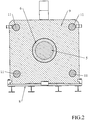
figure 2 shows a sectional view according to line II-II infigure 1 ; -
figure 3 shows a block of the sectional view infigure 2 ; -
figure 4 shows a body of the sectional view infigure 2 ; -
figure 5 shows a cylinder of the sectional view infigure 2 . - An extrusion press 1 able to transform a metal billet profile by plastic deformation (extrusion) comprises a
punch 2 able to push the billet through adie 3. - The billet is supported and guided by a container 4 which limits the expansion thereof during the push through the die and is placed between the punch and the die and guides the billet towards the die.
-
Punch 2 is integral with a screw 5 (see circle A infigure 1 in which the threading ofscrew 5 is depicted on enlarged scale). - Screw 5 engages a
nut screw 6 which substantially is an annular-shaped body with an inner threaded surface. - Said
nut screw 6 is driven to rotation about an axis E ofscrew 5 by one or more electric motors mechanically connected thereto.Figure 1 depicts an annular-shapedelectric motor 7 alone. - Said
electric motor 7 comprises arotor 71 integral with thenut screw 6 and astator 72 integral with abase 8 by ablock 9. - The
nut screw 6 includes a cylindricalouter surface 64 able to slide on a cylindricalinner surface 91 of a cylindrical cavity 93 ofblock 9. - An
interstice 94 is provided between said cylindricalouter surface 64 and said cylindricalinner surface 91, which is able to accommodate lubricating fluid to facilitate the sliding ofbody 6 inblock 9. -
Body 6 further comprises an annular portion 65 (figure 1 ) which abuts againstblock 9, like a portion ofrotor 71, thus axially blocking thebody 6. - The extrusion press 1 further comprises a
shear 10 able to separate the non-extruded end portion of the billet (referred to as a discard) after the extrusion, such as described in International Patent ApplicationWO-2017103828 , for example. - A
cylindrical bar 11 connects the container 4 of the billet withblock 9. Such a connection is made by a screw and a nut screw and is electrically operated. The electrically driven screw-nut screw function aims at moving the billet container 4 along axis E. - Moreover, the extrusion press 1 preferably but not necessarily comprises a lubrication unit able to insert lubricating fluid between
screw 5 andnut screw 6 in order to limit the friction and thus the energy expenditure of theelectric motor 7. - With regard to the operation,
motor 7 rotates thenut screw 6, which allows the translation ofscrew 5 along axis E due to the engagement thereof. - During the extrusion, the
nut screw 6 rotates so as to cause the displacement ofscrew 5, and therefore ofpunch 2, towards the container 4 in which the billet is accommodated (to the right, looking atfigure 1 ). - Once in contact with the billet,
punch 2 pushes the billet through die 3, thus causing the plastic extruded deformation thereof, i.e. generating a profiled element. - Once the extrusion has been complete,
motor 7 reverses the rotation of thenut screw 6, causingscrew 5, and therefore punch 2, to retract, thus returning to a configuration like that depicted infigure 1 . - Advantageously, the push of
punch 2 is caused by an electric motor which directly converts the driving torque thereof into axial force by screw-nut screw motion transmission means without the aid of hydraulic means, i.e. the possible pressurization of hydraulic means does not generate any force which contributes to the required extrusion force. - Preferably, there are between 40 and 60, even more preferably 50 threads engaged in the engagement of
screw 5 andnut screw 6. - Preferably, the surface engaged in said engagement is between 1 m2 and 1.5 m2, even more preferably about 1.38 m2.
- The aforesaid sizes cause a specific load ranging between 1 and 1.5 kg per square millimeter, preferably of 1.3 kg per square millimeter.
- The maximum feeding speed of
cylinder 5 preferably is between 25 and 35 mm/second, preferably 30 mm/second, with a rotation speed preferably being between 25 and 35 revolutions per minute, preferably 27 revolutions per minute corresponding to 0.45 revolutions per second. - The return speed of the cylinder obviously is greater (without a load), preferably between 550 and 650 mm/second, preferably 600 mm/second, with a rotation speed preferably between 800 and 1000 revolutions per minute, preferably 900 revolutions per minute corresponding to 15 revolutions per second.
- Alternatively, instead of
motor 7, there may be a toothed crown on which two or more planetary motors are engaged, the purpose of which is the rotation of the aforesaid crown directly fixed to thenut screw 6. - Advantageously, the screw-nut screw extrusion system allows a reduced volume of the press, increased cleaning, lower maintenance costs and reduced energy costs.
- The push generated by this mechanical system is sufficient for the extrusion of any metal material without the interposition of a compressed fluid and of the complex hydraulic circuits required therein.
- Alternatively, it may be provided that the
nut screw 6 translates along axis E with thepunch 2 integral therewith, and thescrew 5 rotates, thus feeding and pushing the punch forwards, with which it is integral. - The same above-described screw-nut screw pushing system is also applicable with horizontal screws (e.g. four in number), with which respective nut screws are engaged, which move a vertical plate with which the punch is integral, along axis E. This includes the possibility for the nut screws to rotate-translate on the screws, or alternatively for the screws to rotate in order to feed the nut screws which are integral with the vertical plate.
Claims (9)
- An extrusion press (1) of a metal billet, comprising a die (3), a punch (2) able to push the billet through the die (3) and a container (4) of the billet upstream of the die (3),
characterized in that it comprises a screw (5) which the punch (2) is integral to, able to engage with a nut screw (6) comprised in the extrusion press (1),
at least one electric motor (7) driving the reciprocal movement of the screw (5) and of the nut screw (6) thus causing the translation of the punch (2) in the extrusion direction. - An extrusion press (1) according to claim 1, characterized in that the nut screw (6) is driven to rotate about an axis (E) of the screw (5), corresponding to the translation direction of the screw (5) itself, by said at least one electric motor (7).
- An extrusion press (1) according to claim 1, characterized in that the nut screw (6) is fixed and the screw (5) is driven to rotate about an axis (E) of the screw (5), corresponding to the translation direction of the screw (5), at least by said at least one electric motor (7).
- An extrusion press (1) according to claim 1, characterized in that it comprises a plurality of horizontal screws (5) which respective nut screws (6) engage with, thus causing the translation in the extrusion direction of a vertical plate which the punch (2) is integral to.
- An extrusion press (1) according to any one of the preceding claims, characterized in that it comprises a lubrication unit able to insert lubricating fluid between the screw (5) and the nut screw (6).
- An extrusion press (1) according to claim 2 , characterized in that said at least one electric motor (7) comprises a rotor (71) integral with the nut screw (6), and a stator (72) integral with a base (8).
- An extrusion press (1) according to claim 2 , characterized in that said at least one electric motor (7) comprises planetary motors able to engage with a crown integral to the nut screw (6).
- An extrusion press (1) according to claim 6 or claim 7 , characterized in that it comprises a block (9) which provides a cylindrical inner surface (91) of a cylindrical cavity (93) on which a cylindrical outer surface (64) of the nut screw (6) slides.
- An extrusion press (1) according to claim 8, characterized in that an interstice (94) is provided between said cylindrical outer surface (64) and said cylindrical inner surface (91), able to accommodate lubricating fluid to facilitate the sliding of the nut screw (6) in the block (9).
Applications Claiming Priority (1)
| Application Number | Priority Date | Filing Date | Title |
|---|---|---|---|
| IT102017000115300A IT201700115300A1 (en) | 2017-10-12 | 2017-10-12 | Extrusion press with direct mechanical actuation. |
Publications (2)
| Publication Number | Publication Date |
|---|---|
| EP3470146A1 EP3470146A1 (en) | 2019-04-17 |
| EP3470146B1 true EP3470146B1 (en) | 2020-08-19 |
Family
ID=61224300
Family Applications (1)
| Application Number | Title | Priority Date | Filing Date |
|---|---|---|---|
| EP18199519.2A Active EP3470146B1 (en) | 2017-10-12 | 2018-10-10 | Direct mechanically-operated extrusion press |
Country Status (4)
| Country | Link |
|---|---|
| US (1) | US20190111460A1 (en) |
| EP (1) | EP3470146B1 (en) |
| ES (1) | ES2832876T3 (en) |
| IT (1) | IT201700115300A1 (en) |
Cited By (3)
| Publication number | Priority date | Publication date | Assignee | Title |
|---|---|---|---|---|
| DE102023100729A1 (en) | 2022-11-14 | 2024-05-16 | Sms Group Gmbh | Extrusion press |
| DE102023105916A1 (en) | 2022-11-14 | 2024-05-16 | Sms Group Gmbh | Extrusion press |
| DE102023126321A1 (en) | 2023-09-27 | 2025-03-27 | Sms Group Gmbh | Extrusion press |
Families Citing this family (1)
| Publication number | Priority date | Publication date | Assignee | Title |
|---|---|---|---|---|
| KR20240070410A (en) * | 2022-11-14 | 2024-05-21 | 에스엠에스 그룹 게엠베하 | Extrusion press |
Family Cites Families (8)
| Publication number | Priority date | Publication date | Assignee | Title |
|---|---|---|---|---|
| DE19605885C1 (en) * | 1996-02-05 | 1997-08-21 | Alusuisse Lonza Services Ag | Extruding profile or similar item from ingot |
| WO2006084175A2 (en) * | 2005-02-04 | 2006-08-10 | Alcoa Inc. | Extruded monolithic aluminum trailer landing gear foot and method of making same |
| KR101049629B1 (en) | 2006-10-16 | 2011-07-14 | 우베 고산 기카이 가부시키가이샤 | Stem slide device |
| US8490453B2 (en) * | 2009-04-15 | 2013-07-23 | Ube Machinery Corporation, Ltd. | Extrusion press |
| JP5382137B2 (en) * | 2009-12-14 | 2014-01-08 | 宇部興産機械株式会社 | Extrusion press |
| KR20170065491A (en) * | 2014-10-06 | 2017-06-13 | 우베 고산 기카이 가부시키가이샤 | Extrusion press |
| JP2016163901A (en) * | 2015-03-06 | 2016-09-08 | 宇部興産機械株式会社 | Hybrid extrusion press |
| CN107249769B (en) | 2015-03-09 | 2019-02-15 | 宇部兴产机械株式会社 | Die sliding device for extruder |
-
2017
- 2017-10-12 IT IT102017000115300A patent/IT201700115300A1/en unknown
-
2018
- 2018-10-10 ES ES18199519T patent/ES2832876T3/en active Active
- 2018-10-10 EP EP18199519.2A patent/EP3470146B1/en active Active
- 2018-10-12 US US16/158,364 patent/US20190111460A1/en not_active Abandoned
Non-Patent Citations (1)
| Title |
|---|
| None * |
Cited By (5)
| Publication number | Priority date | Publication date | Assignee | Title |
|---|---|---|---|---|
| DE102023100729A1 (en) | 2022-11-14 | 2024-05-16 | Sms Group Gmbh | Extrusion press |
| DE102023105916A1 (en) | 2022-11-14 | 2024-05-16 | Sms Group Gmbh | Extrusion press |
| DE102023126321A1 (en) | 2023-09-27 | 2025-03-27 | Sms Group Gmbh | Extrusion press |
| WO2025068189A1 (en) | 2023-09-27 | 2025-04-03 | Sms Group Gmbh | Extrusion press |
| DE102023126321B4 (en) * | 2023-09-27 | 2025-07-24 | Sms Group Gmbh | Extrusion press |
Also Published As
| Publication number | Publication date |
|---|---|
| IT201700115300A1 (en) | 2019-04-12 |
| EP3470146A1 (en) | 2019-04-17 |
| ES2832876T3 (en) | 2021-06-11 |
| US20190111460A1 (en) | 2019-04-18 |
Similar Documents
| Publication | Publication Date | Title |
|---|---|---|
| EP3470146A1 (en) | Direct mechanically-operated extrusion press | |
| JP6460116B2 (en) | Extrusion press | |
| DE60320596T2 (en) | INJECTION UNIT WITH A DRIVE ARRANGEMENT FOR TURNING AND TRANSLATORY MOVEMENT OF A SHAFT | |
| EP3750643B1 (en) | Stretching machine for extruded profiles | |
| US20180015517A1 (en) | Die-slide device of extrusion press | |
| EP3697516B1 (en) | Filter press and method for separating the solid components from the liquid components of a slurry | |
| US20120244239A1 (en) | Extrusion press | |
| CN104972026B (en) | Forming machine | |
| EP1283770A1 (en) | Drive device, in particular for the locking unit, the injection unit or the ejector of an injection-moulding machine for plastics | |
| EP3104992B1 (en) | Forging machine and method | |
| CN103671302A (en) | Hinge rod hydraulic pressurizing device and hydraulic press machine | |
| CN103909668A (en) | Mechanical idle-stroke and electric supercharge servo energy-saving hydraulic machine with oilless pumps | |
| CN104810989A (en) | Stator iron core lamination tool | |
| US11154920B2 (en) | Rolling mill for rolling concave, rod-shaped bodies | |
| EP2830867B1 (en) | Pressure cartridge | |
| US10507504B2 (en) | Hybrid extrusion press | |
| CN110280615B (en) | Device and method for rapidly replacing and locking extrusion shaft | |
| CN112547904A (en) | Mold equipment for side positioning | |
| EP2295825A2 (en) | Combined brake and clutch device for presses | |
| JP2016043370A (en) | Extrusion press | |
| CN102172721B (en) | Riveting machine for radiator | |
| CN210411956U (en) | Extrusion shaft quick replacement and locking device | |
| TW201600192A (en) | Bar press with hydraulic drive | |
| CN202037264U (en) | Radiator riveting machine | |
| CN107000356A (en) | The sliding block locking device of stamping machine |
Legal Events
| Date | Code | Title | Description |
|---|---|---|---|
| PUAI | Public reference made under article 153(3) epc to a published international application that has entered the european phase |
Free format text: ORIGINAL CODE: 0009012 |
|
| STAA | Information on the status of an ep patent application or granted ep patent |
Free format text: STATUS: THE APPLICATION HAS BEEN PUBLISHED |
|
| AK | Designated contracting states |
Kind code of ref document: A1 Designated state(s): AL AT BE BG CH CY CZ DE DK EE ES FI FR GB GR HR HU IE IS IT LI LT LU LV MC MK MT NL NO PL PT RO RS SE SI SK SM TR |
|
| AX | Request for extension of the european patent |
Extension state: BA ME |
|
| STAA | Information on the status of an ep patent application or granted ep patent |
Free format text: STATUS: REQUEST FOR EXAMINATION WAS MADE |
|
| 17P | Request for examination filed |
Effective date: 20191009 |
|
| RBV | Designated contracting states (corrected) |
Designated state(s): AL AT BE BG CH CY CZ DE DK EE ES FI FR GB GR HR HU IE IS IT LI LT LU LV MC MK MT NL NO PL PT RO RS SE SI SK SM TR |
|
| GRAP | Despatch of communication of intention to grant a patent |
Free format text: ORIGINAL CODE: EPIDOSNIGR1 |
|
| STAA | Information on the status of an ep patent application or granted ep patent |
Free format text: STATUS: GRANT OF PATENT IS INTENDED |
|
| INTG | Intention to grant announced |
Effective date: 20200325 |
|
| GRAS | Grant fee paid |
Free format text: ORIGINAL CODE: EPIDOSNIGR3 |
|
| GRAA | (expected) grant |
Free format text: ORIGINAL CODE: 0009210 |
|
| STAA | Information on the status of an ep patent application or granted ep patent |
Free format text: STATUS: THE PATENT HAS BEEN GRANTED |
|
| AK | Designated contracting states |
Kind code of ref document: B1 Designated state(s): AL AT BE BG CH CY CZ DE DK EE ES FI FR GB GR HR HU IE IS IT LI LT LU LV MC MK MT NL NO PL PT RO RS SE SI SK SM TR |
|
| REG | Reference to a national code |
Ref country code: CH Ref legal event code: EP |
|
| REG | Reference to a national code |
Ref country code: DE Ref legal event code: R096 Ref document number: 602018007058 Country of ref document: DE |
|
| REG | Reference to a national code |
Ref country code: AT Ref legal event code: REF Ref document number: 1303352 Country of ref document: AT Kind code of ref document: T Effective date: 20200915 |
|
| REG | Reference to a national code |
Ref country code: IE Ref legal event code: FG4D |
|
| REG | Reference to a national code |
Ref country code: LT Ref legal event code: MG4D |
|
| REG | Reference to a national code |
Ref country code: NL Ref legal event code: MP Effective date: 20200819 |
|
| PG25 | Lapsed in a contracting state [announced via postgrant information from national office to epo] |
Ref country code: PT Free format text: LAPSE BECAUSE OF FAILURE TO SUBMIT A TRANSLATION OF THE DESCRIPTION OR TO PAY THE FEE WITHIN THE PRESCRIBED TIME-LIMIT Effective date: 20201221 Ref country code: SE Free format text: LAPSE BECAUSE OF FAILURE TO SUBMIT A TRANSLATION OF THE DESCRIPTION OR TO PAY THE FEE WITHIN THE PRESCRIBED TIME-LIMIT Effective date: 20200819 Ref country code: FI Free format text: LAPSE BECAUSE OF FAILURE TO SUBMIT A TRANSLATION OF THE DESCRIPTION OR TO PAY THE FEE WITHIN THE PRESCRIBED TIME-LIMIT Effective date: 20200819 Ref country code: NO Free format text: LAPSE BECAUSE OF FAILURE TO SUBMIT A TRANSLATION OF THE DESCRIPTION OR TO PAY THE FEE WITHIN THE PRESCRIBED TIME-LIMIT Effective date: 20201119 Ref country code: HR Free format text: LAPSE BECAUSE OF FAILURE TO SUBMIT A TRANSLATION OF THE DESCRIPTION OR TO PAY THE FEE WITHIN THE PRESCRIBED TIME-LIMIT Effective date: 20200819 Ref country code: BG Free format text: LAPSE BECAUSE OF FAILURE TO SUBMIT A TRANSLATION OF THE DESCRIPTION OR TO PAY THE FEE WITHIN THE PRESCRIBED TIME-LIMIT Effective date: 20201119 Ref country code: LT Free format text: LAPSE BECAUSE OF FAILURE TO SUBMIT A TRANSLATION OF THE DESCRIPTION OR TO PAY THE FEE WITHIN THE PRESCRIBED TIME-LIMIT Effective date: 20200819 Ref country code: GR Free format text: LAPSE BECAUSE OF FAILURE TO SUBMIT A TRANSLATION OF THE DESCRIPTION OR TO PAY THE FEE WITHIN THE PRESCRIBED TIME-LIMIT Effective date: 20201120 |
|
| REG | Reference to a national code |
Ref country code: AT Ref legal event code: MK05 Ref document number: 1303352 Country of ref document: AT Kind code of ref document: T Effective date: 20200819 |
|
| PG25 | Lapsed in a contracting state [announced via postgrant information from national office to epo] |
Ref country code: NL Free format text: LAPSE BECAUSE OF FAILURE TO SUBMIT A TRANSLATION OF THE DESCRIPTION OR TO PAY THE FEE WITHIN THE PRESCRIBED TIME-LIMIT Effective date: 20200819 Ref country code: PL Free format text: LAPSE BECAUSE OF FAILURE TO SUBMIT A TRANSLATION OF THE DESCRIPTION OR TO PAY THE FEE WITHIN THE PRESCRIBED TIME-LIMIT Effective date: 20200819 Ref country code: LV Free format text: LAPSE BECAUSE OF FAILURE TO SUBMIT A TRANSLATION OF THE DESCRIPTION OR TO PAY THE FEE WITHIN THE PRESCRIBED TIME-LIMIT Effective date: 20200819 Ref country code: RS Free format text: LAPSE BECAUSE OF FAILURE TO SUBMIT A TRANSLATION OF THE DESCRIPTION OR TO PAY THE FEE WITHIN THE PRESCRIBED TIME-LIMIT Effective date: 20200819 Ref country code: IS Free format text: LAPSE BECAUSE OF FAILURE TO SUBMIT A TRANSLATION OF THE DESCRIPTION OR TO PAY THE FEE WITHIN THE PRESCRIBED TIME-LIMIT Effective date: 20201219 |
|
| PG25 | Lapsed in a contracting state [announced via postgrant information from national office to epo] |
Ref country code: RO Free format text: LAPSE BECAUSE OF FAILURE TO SUBMIT A TRANSLATION OF THE DESCRIPTION OR TO PAY THE FEE WITHIN THE PRESCRIBED TIME-LIMIT Effective date: 20200819 Ref country code: CZ Free format text: LAPSE BECAUSE OF FAILURE TO SUBMIT A TRANSLATION OF THE DESCRIPTION OR TO PAY THE FEE WITHIN THE PRESCRIBED TIME-LIMIT Effective date: 20200819 Ref country code: DK Free format text: LAPSE BECAUSE OF FAILURE TO SUBMIT A TRANSLATION OF THE DESCRIPTION OR TO PAY THE FEE WITHIN THE PRESCRIBED TIME-LIMIT Effective date: 20200819 Ref country code: EE Free format text: LAPSE BECAUSE OF FAILURE TO SUBMIT A TRANSLATION OF THE DESCRIPTION OR TO PAY THE FEE WITHIN THE PRESCRIBED TIME-LIMIT Effective date: 20200819 Ref country code: SM Free format text: LAPSE BECAUSE OF FAILURE TO SUBMIT A TRANSLATION OF THE DESCRIPTION OR TO PAY THE FEE WITHIN THE PRESCRIBED TIME-LIMIT Effective date: 20200819 |
|
| REG | Reference to a national code |
Ref country code: DE Ref legal event code: R097 Ref document number: 602018007058 Country of ref document: DE |
|
| PG25 | Lapsed in a contracting state [announced via postgrant information from national office to epo] |
Ref country code: AT Free format text: LAPSE BECAUSE OF FAILURE TO SUBMIT A TRANSLATION OF THE DESCRIPTION OR TO PAY THE FEE WITHIN THE PRESCRIBED TIME-LIMIT Effective date: 20200819 Ref country code: AL Free format text: LAPSE BECAUSE OF FAILURE TO SUBMIT A TRANSLATION OF THE DESCRIPTION OR TO PAY THE FEE WITHIN THE PRESCRIBED TIME-LIMIT Effective date: 20200819 |
|
| REG | Reference to a national code |
Ref country code: ES Ref legal event code: FG2A Ref document number: 2832876 Country of ref document: ES Kind code of ref document: T3 Effective date: 20210611 |
|
| PLBE | No opposition filed within time limit |
Free format text: ORIGINAL CODE: 0009261 |
|
| STAA | Information on the status of an ep patent application or granted ep patent |
Free format text: STATUS: NO OPPOSITION FILED WITHIN TIME LIMIT |
|
| PG25 | Lapsed in a contracting state [announced via postgrant information from national office to epo] |
Ref country code: SK Free format text: LAPSE BECAUSE OF FAILURE TO SUBMIT A TRANSLATION OF THE DESCRIPTION OR TO PAY THE FEE WITHIN THE PRESCRIBED TIME-LIMIT Effective date: 20200819 Ref country code: MC Free format text: LAPSE BECAUSE OF FAILURE TO SUBMIT A TRANSLATION OF THE DESCRIPTION OR TO PAY THE FEE WITHIN THE PRESCRIBED TIME-LIMIT Effective date: 20200819 Ref country code: LU Free format text: LAPSE BECAUSE OF NON-PAYMENT OF DUE FEES Effective date: 20201010 |
|
| REG | Reference to a national code |
Ref country code: BE Ref legal event code: MM Effective date: 20201031 |
|
| 26N | No opposition filed |
Effective date: 20210520 |
|
| PG25 | Lapsed in a contracting state [announced via postgrant information from national office to epo] |
Ref country code: FR Free format text: LAPSE BECAUSE OF NON-PAYMENT OF DUE FEES Effective date: 20201019 |
|
| PG25 | Lapsed in a contracting state [announced via postgrant information from national office to epo] |
Ref country code: SI Free format text: LAPSE BECAUSE OF FAILURE TO SUBMIT A TRANSLATION OF THE DESCRIPTION OR TO PAY THE FEE WITHIN THE PRESCRIBED TIME-LIMIT Effective date: 20200819 Ref country code: BE Free format text: LAPSE BECAUSE OF NON-PAYMENT OF DUE FEES Effective date: 20201031 |
|
| PG25 | Lapsed in a contracting state [announced via postgrant information from national office to epo] |
Ref country code: IE Free format text: LAPSE BECAUSE OF NON-PAYMENT OF DUE FEES Effective date: 20201010 |
|
| PGFP | Annual fee paid to national office [announced via postgrant information from national office to epo] |
Ref country code: IT Payment date: 20211031 Year of fee payment: 4 |
|
| REG | Reference to a national code |
Ref country code: DE Ref legal event code: R081 Ref document number: 602018007058 Country of ref document: DE Owner name: EMPRESS TECHNOLOGY SAGL, CH Free format text: FORMER OWNER: TURLA, DAVIDE, VILLA CARCINA, IT |
|
| PGFP | Annual fee paid to national office [announced via postgrant information from national office to epo] |
Ref country code: DE Payment date: 20211223 Year of fee payment: 4 |
|
| REG | Reference to a national code |
Ref country code: ES Ref legal event code: PC2A Owner name: EMPRESS TECHNOLOGY SAGL Effective date: 20220510 |
|
| REG | Reference to a national code |
Ref country code: CH Ref legal event code: PL |
|
| PG25 | Lapsed in a contracting state [announced via postgrant information from national office to epo] |
Ref country code: TR Free format text: LAPSE BECAUSE OF FAILURE TO SUBMIT A TRANSLATION OF THE DESCRIPTION OR TO PAY THE FEE WITHIN THE PRESCRIBED TIME-LIMIT Effective date: 20200819 Ref country code: MT Free format text: LAPSE BECAUSE OF FAILURE TO SUBMIT A TRANSLATION OF THE DESCRIPTION OR TO PAY THE FEE WITHIN THE PRESCRIBED TIME-LIMIT Effective date: 20200819 Ref country code: CY Free format text: LAPSE BECAUSE OF FAILURE TO SUBMIT A TRANSLATION OF THE DESCRIPTION OR TO PAY THE FEE WITHIN THE PRESCRIBED TIME-LIMIT Effective date: 20200819 |
|
| PGFP | Annual fee paid to national office [announced via postgrant information from national office to epo] |
Ref country code: ES Payment date: 20220110 Year of fee payment: 4 |
|
| PG25 | Lapsed in a contracting state [announced via postgrant information from national office to epo] |
Ref country code: MK Free format text: LAPSE BECAUSE OF FAILURE TO SUBMIT A TRANSLATION OF THE DESCRIPTION OR TO PAY THE FEE WITHIN THE PRESCRIBED TIME-LIMIT Effective date: 20200819 |
|
| PG25 | Lapsed in a contracting state [announced via postgrant information from national office to epo] |
Ref country code: LI Free format text: LAPSE BECAUSE OF NON-PAYMENT OF DUE FEES Effective date: 20211031 Ref country code: CH Free format text: LAPSE BECAUSE OF NON-PAYMENT OF DUE FEES Effective date: 20211031 |
|
| REG | Reference to a national code |
Ref country code: DE Ref legal event code: R119 Ref document number: 602018007058 Country of ref document: DE |
|
| GBPC | Gb: european patent ceased through non-payment of renewal fee |
Effective date: 20221010 |
|
| PG25 | Lapsed in a contracting state [announced via postgrant information from national office to epo] |
Ref country code: DE Free format text: LAPSE BECAUSE OF NON-PAYMENT OF DUE FEES Effective date: 20230503 |
|
| PG25 | Lapsed in a contracting state [announced via postgrant information from national office to epo] |
Ref country code: IT Free format text: LAPSE BECAUSE OF NON-PAYMENT OF DUE FEES Effective date: 20221010 Ref country code: GB Free format text: LAPSE BECAUSE OF NON-PAYMENT OF DUE FEES Effective date: 20221010 |
|
| REG | Reference to a national code |
Ref country code: ES Ref legal event code: FD2A Effective date: 20231124 |
|
| PG25 | Lapsed in a contracting state [announced via postgrant information from national office to epo] |
Ref country code: ES Free format text: LAPSE BECAUSE OF NON-PAYMENT OF DUE FEES Effective date: 20221011 |
|
| PG25 | Lapsed in a contracting state [announced via postgrant information from national office to epo] |
Ref country code: ES Free format text: LAPSE BECAUSE OF NON-PAYMENT OF DUE FEES Effective date: 20221011 |