EP3470137A1 - Dispositif comprenant des injections laterales de liquide pour limiter les phenomenes de depots solides dans les equipements a fond conique - Google Patents
Dispositif comprenant des injections laterales de liquide pour limiter les phenomenes de depots solides dans les equipements a fond conique Download PDFInfo
- Publication number
- EP3470137A1 EP3470137A1 EP18199193.6A EP18199193A EP3470137A1 EP 3470137 A1 EP3470137 A1 EP 3470137A1 EP 18199193 A EP18199193 A EP 18199193A EP 3470137 A1 EP3470137 A1 EP 3470137A1
- Authority
- EP
- European Patent Office
- Prior art keywords
- liquid
- injections
- equipment
- angle
- injection
- Prior art date
- Legal status (The legal status is an assumption and is not a legal conclusion. Google has not performed a legal analysis and makes no representation as to the accuracy of the status listed.)
- Granted
Links
Images


Classifications
-
- C—CHEMISTRY; METALLURGY
- C10—PETROLEUM, GAS OR COKE INDUSTRIES; TECHNICAL GASES CONTAINING CARBON MONOXIDE; FUELS; LUBRICANTS; PEAT
- C10G—CRACKING HYDROCARBON OILS; PRODUCTION OF LIQUID HYDROCARBON MIXTURES, e.g. BY DESTRUCTIVE HYDROGENATION, OLIGOMERISATION, POLYMERISATION; RECOVERY OF HYDROCARBON OILS FROM OIL-SHALE, OIL-SAND, OR GASES; REFINING MIXTURES MAINLY CONSISTING OF HYDROCARBONS; REFORMING OF NAPHTHA; MINERAL WAXES
- C10G75/00—Inhibiting corrosion or fouling in apparatus for treatment or conversion of hydrocarbon oils, in general
-
- B—PERFORMING OPERATIONS; TRANSPORTING
- B01—PHYSICAL OR CHEMICAL PROCESSES OR APPARATUS IN GENERAL
- B01J—CHEMICAL OR PHYSICAL PROCESSES, e.g. CATALYSIS OR COLLOID CHEMISTRY; THEIR RELEVANT APPARATUS
- B01J8/00—Chemical or physical processes in general, conducted in the presence of fluids and solid particles; Apparatus for such processes
- B01J8/18—Chemical or physical processes in general, conducted in the presence of fluids and solid particles; Apparatus for such processes with fluidised particles
- B01J8/20—Chemical or physical processes in general, conducted in the presence of fluids and solid particles; Apparatus for such processes with fluidised particles with liquid as a fluidising medium
- B01J8/22—Chemical or physical processes in general, conducted in the presence of fluids and solid particles; Apparatus for such processes with fluidised particles with liquid as a fluidising medium gas being introduced into the liquid
- B01J8/224—Chemical or physical processes in general, conducted in the presence of fluids and solid particles; Apparatus for such processes with fluidised particles with liquid as a fluidising medium gas being introduced into the liquid the particles being subject to a circulatory movement
- B01J8/228—Chemical or physical processes in general, conducted in the presence of fluids and solid particles; Apparatus for such processes with fluidised particles with liquid as a fluidising medium gas being introduced into the liquid the particles being subject to a circulatory movement externally, i.e. the particles leaving the vessel and subsequently re-entering it
-
- B—PERFORMING OPERATIONS; TRANSPORTING
- B01—PHYSICAL OR CHEMICAL PROCESSES OR APPARATUS IN GENERAL
- B01J—CHEMICAL OR PHYSICAL PROCESSES, e.g. CATALYSIS OR COLLOID CHEMISTRY; THEIR RELEVANT APPARATUS
- B01J19/00—Chemical, physical or physico-chemical processes in general; Their relevant apparatus
-
- B—PERFORMING OPERATIONS; TRANSPORTING
- B01—PHYSICAL OR CHEMICAL PROCESSES OR APPARATUS IN GENERAL
- B01J—CHEMICAL OR PHYSICAL PROCESSES, e.g. CATALYSIS OR COLLOID CHEMISTRY; THEIR RELEVANT APPARATUS
- B01J19/00—Chemical, physical or physico-chemical processes in general; Their relevant apparatus
- B01J19/24—Stationary reactors without moving elements inside
-
- B—PERFORMING OPERATIONS; TRANSPORTING
- B01—PHYSICAL OR CHEMICAL PROCESSES OR APPARATUS IN GENERAL
- B01D—SEPARATION
- B01D3/00—Distillation or related exchange processes in which liquids are contacted with gaseous media, e.g. stripping
-
- B—PERFORMING OPERATIONS; TRANSPORTING
- B01—PHYSICAL OR CHEMICAL PROCESSES OR APPARATUS IN GENERAL
- B01J—CHEMICAL OR PHYSICAL PROCESSES, e.g. CATALYSIS OR COLLOID CHEMISTRY; THEIR RELEVANT APPARATUS
- B01J19/00—Chemical, physical or physico-chemical processes in general; Their relevant apparatus
- B01J19/24—Stationary reactors without moving elements inside
- B01J19/2455—Stationary reactors without moving elements inside provoking a loop type movement of the reactants
- B01J19/2465—Stationary reactors without moving elements inside provoking a loop type movement of the reactants externally, i.e. the mixture leaving the vessel and subsequently re-entering it
-
- B—PERFORMING OPERATIONS; TRANSPORTING
- B01—PHYSICAL OR CHEMICAL PROCESSES OR APPARATUS IN GENERAL
- B01J—CHEMICAL OR PHYSICAL PROCESSES, e.g. CATALYSIS OR COLLOID CHEMISTRY; THEIR RELEVANT APPARATUS
- B01J19/00—Chemical, physical or physico-chemical processes in general; Their relevant apparatus
- B01J19/26—Nozzle-type reactors, i.e. the distribution of the initial reactants within the reactor is effected by their introduction or injection through nozzles
-
- B—PERFORMING OPERATIONS; TRANSPORTING
- B01—PHYSICAL OR CHEMICAL PROCESSES OR APPARATUS IN GENERAL
- B01J—CHEMICAL OR PHYSICAL PROCESSES, e.g. CATALYSIS OR COLLOID CHEMISTRY; THEIR RELEVANT APPARATUS
- B01J8/00—Chemical or physical processes in general, conducted in the presence of fluids and solid particles; Apparatus for such processes
- B01J8/08—Chemical or physical processes in general, conducted in the presence of fluids and solid particles; Apparatus for such processes with moving particles
- B01J8/085—Feeding reactive fluids
-
- B—PERFORMING OPERATIONS; TRANSPORTING
- B01—PHYSICAL OR CHEMICAL PROCESSES OR APPARATUS IN GENERAL
- B01J—CHEMICAL OR PHYSICAL PROCESSES, e.g. CATALYSIS OR COLLOID CHEMISTRY; THEIR RELEVANT APPARATUS
- B01J8/00—Chemical or physical processes in general, conducted in the presence of fluids and solid particles; Apparatus for such processes
- B01J8/18—Chemical or physical processes in general, conducted in the presence of fluids and solid particles; Apparatus for such processes with fluidised particles
- B01J8/1881—Chemical or physical processes in general, conducted in the presence of fluids and solid particles; Apparatus for such processes with fluidised particles with particles moving downwards while fluidised
-
- C—CHEMISTRY; METALLURGY
- C10—PETROLEUM, GAS OR COKE INDUSTRIES; TECHNICAL GASES CONTAINING CARBON MONOXIDE; FUELS; LUBRICANTS; PEAT
- C10G—CRACKING HYDROCARBON OILS; PRODUCTION OF LIQUID HYDROCARBON MIXTURES, e.g. BY DESTRUCTIVE HYDROGENATION, OLIGOMERISATION, POLYMERISATION; RECOVERY OF HYDROCARBON OILS FROM OIL-SHALE, OIL-SAND, OR GASES; REFINING MIXTURES MAINLY CONSISTING OF HYDROCARBONS; REFORMING OF NAPHTHA; MINERAL WAXES
- C10G47/00—Cracking of hydrocarbon oils, in the presence of hydrogen or hydrogen- generating compounds, to obtain lower boiling fractions
- C10G47/24—Cracking of hydrocarbon oils, in the presence of hydrogen or hydrogen- generating compounds, to obtain lower boiling fractions with moving solid particles
- C10G47/26—Cracking of hydrocarbon oils, in the presence of hydrogen or hydrogen- generating compounds, to obtain lower boiling fractions with moving solid particles suspended in the oil, e.g. slurries
-
- C—CHEMISTRY; METALLURGY
- C10—PETROLEUM, GAS OR COKE INDUSTRIES; TECHNICAL GASES CONTAINING CARBON MONOXIDE; FUELS; LUBRICANTS; PEAT
- C10G—CRACKING HYDROCARBON OILS; PRODUCTION OF LIQUID HYDROCARBON MIXTURES, e.g. BY DESTRUCTIVE HYDROGENATION, OLIGOMERISATION, POLYMERISATION; RECOVERY OF HYDROCARBON OILS FROM OIL-SHALE, OIL-SAND, OR GASES; REFINING MIXTURES MAINLY CONSISTING OF HYDROCARBONS; REFORMING OF NAPHTHA; MINERAL WAXES
- C10G51/00—Treatment of hydrocarbon oils, in the absence of hydrogen, by two or more cracking processes only
- C10G51/02—Treatment of hydrocarbon oils, in the absence of hydrogen, by two or more cracking processes only plural serial stages only
- C10G51/04—Treatment of hydrocarbon oils, in the absence of hydrogen, by two or more cracking processes only plural serial stages only including only thermal and catalytic cracking steps
-
- C—CHEMISTRY; METALLURGY
- C10—PETROLEUM, GAS OR COKE INDUSTRIES; TECHNICAL GASES CONTAINING CARBON MONOXIDE; FUELS; LUBRICANTS; PEAT
- C10G—CRACKING HYDROCARBON OILS; PRODUCTION OF LIQUID HYDROCARBON MIXTURES, e.g. BY DESTRUCTIVE HYDROGENATION, OLIGOMERISATION, POLYMERISATION; RECOVERY OF HYDROCARBON OILS FROM OIL-SHALE, OIL-SAND, OR GASES; REFINING MIXTURES MAINLY CONSISTING OF HYDROCARBONS; REFORMING OF NAPHTHA; MINERAL WAXES
- C10G65/00—Treatment of hydrocarbon oils by two or more hydrotreatment processes only
- C10G65/02—Treatment of hydrocarbon oils by two or more hydrotreatment processes only plural serial stages only
- C10G65/10—Treatment of hydrocarbon oils by two or more hydrotreatment processes only plural serial stages only including only cracking steps
-
- C—CHEMISTRY; METALLURGY
- C10—PETROLEUM, GAS OR COKE INDUSTRIES; TECHNICAL GASES CONTAINING CARBON MONOXIDE; FUELS; LUBRICANTS; PEAT
- C10G—CRACKING HYDROCARBON OILS; PRODUCTION OF LIQUID HYDROCARBON MIXTURES, e.g. BY DESTRUCTIVE HYDROGENATION, OLIGOMERISATION, POLYMERISATION; RECOVERY OF HYDROCARBON OILS FROM OIL-SHALE, OIL-SAND, OR GASES; REFINING MIXTURES MAINLY CONSISTING OF HYDROCARBONS; REFORMING OF NAPHTHA; MINERAL WAXES
- C10G65/00—Treatment of hydrocarbon oils by two or more hydrotreatment processes only
- C10G65/02—Treatment of hydrocarbon oils by two or more hydrotreatment processes only plural serial stages only
- C10G65/12—Treatment of hydrocarbon oils by two or more hydrotreatment processes only plural serial stages only including cracking steps and other hydrotreatment steps
-
- C—CHEMISTRY; METALLURGY
- C10—PETROLEUM, GAS OR COKE INDUSTRIES; TECHNICAL GASES CONTAINING CARBON MONOXIDE; FUELS; LUBRICANTS; PEAT
- C10G—CRACKING HYDROCARBON OILS; PRODUCTION OF LIQUID HYDROCARBON MIXTURES, e.g. BY DESTRUCTIVE HYDROGENATION, OLIGOMERISATION, POLYMERISATION; RECOVERY OF HYDROCARBON OILS FROM OIL-SHALE, OIL-SAND, OR GASES; REFINING MIXTURES MAINLY CONSISTING OF HYDROCARBONS; REFORMING OF NAPHTHA; MINERAL WAXES
- C10G67/00—Treatment of hydrocarbon oils by at least one hydrotreatment process and at least one process for refining in the absence of hydrogen only
- C10G67/02—Treatment of hydrocarbon oils by at least one hydrotreatment process and at least one process for refining in the absence of hydrogen only plural serial stages only
- C10G67/04—Treatment of hydrocarbon oils by at least one hydrotreatment process and at least one process for refining in the absence of hydrogen only plural serial stages only including solvent extraction as the refining step in the absence of hydrogen
- C10G67/0454—Solvent desasphalting
- C10G67/049—The hydrotreatment being a hydrocracking
-
- B—PERFORMING OPERATIONS; TRANSPORTING
- B01—PHYSICAL OR CHEMICAL PROCESSES OR APPARATUS IN GENERAL
- B01J—CHEMICAL OR PHYSICAL PROCESSES, e.g. CATALYSIS OR COLLOID CHEMISTRY; THEIR RELEVANT APPARATUS
- B01J2208/00—Processes carried out in the presence of solid particles; Reactors therefor
- B01J2208/00796—Details of the reactor or of the particulate material
- B01J2208/00893—Feeding means for the reactants
-
- B—PERFORMING OPERATIONS; TRANSPORTING
- B01—PHYSICAL OR CHEMICAL PROCESSES OR APPARATUS IN GENERAL
- B01J—CHEMICAL OR PHYSICAL PROCESSES, e.g. CATALYSIS OR COLLOID CHEMISTRY; THEIR RELEVANT APPARATUS
- B01J2219/00—Chemical, physical or physico-chemical processes in general; Their relevant apparatus
- B01J2219/00049—Controlling or regulating processes
- B01J2219/00245—Avoiding undesirable reactions or side-effects
- B01J2219/00247—Fouling of the reactor or the process equipment
-
- B—PERFORMING OPERATIONS; TRANSPORTING
- B01—PHYSICAL OR CHEMICAL PROCESSES OR APPARATUS IN GENERAL
- B01J—CHEMICAL OR PHYSICAL PROCESSES, e.g. CATALYSIS OR COLLOID CHEMISTRY; THEIR RELEVANT APPARATUS
- B01J2219/00—Chemical, physical or physico-chemical processes in general; Their relevant apparatus
- B01J2219/00049—Controlling or regulating processes
- B01J2219/00245—Avoiding undesirable reactions or side-effects
- B01J2219/00252—Formation of deposits other than coke
-
- B—PERFORMING OPERATIONS; TRANSPORTING
- B01—PHYSICAL OR CHEMICAL PROCESSES OR APPARATUS IN GENERAL
- B01J—CHEMICAL OR PHYSICAL PROCESSES, e.g. CATALYSIS OR COLLOID CHEMISTRY; THEIR RELEVANT APPARATUS
- B01J2219/00—Chemical, physical or physico-chemical processes in general; Their relevant apparatus
- B01J2219/18—Details relating to the spatial orientation of the reactor
- B01J2219/185—Details relating to the spatial orientation of the reactor vertical
-
- B—PERFORMING OPERATIONS; TRANSPORTING
- B01—PHYSICAL OR CHEMICAL PROCESSES OR APPARATUS IN GENERAL
- B01J—CHEMICAL OR PHYSICAL PROCESSES, e.g. CATALYSIS OR COLLOID CHEMISTRY; THEIR RELEVANT APPARATUS
- B01J2219/00—Chemical, physical or physico-chemical processes in general; Their relevant apparatus
- B01J2219/19—Details relating to the geometry of the reactor
- B01J2219/194—Details relating to the geometry of the reactor round
- B01J2219/1941—Details relating to the geometry of the reactor round circular or disk-shaped
- B01J2219/1943—Details relating to the geometry of the reactor round circular or disk-shaped cylindrical
-
- B—PERFORMING OPERATIONS; TRANSPORTING
- B01—PHYSICAL OR CHEMICAL PROCESSES OR APPARATUS IN GENERAL
- B01J—CHEMICAL OR PHYSICAL PROCESSES, e.g. CATALYSIS OR COLLOID CHEMISTRY; THEIR RELEVANT APPARATUS
- B01J2219/00—Chemical, physical or physico-chemical processes in general; Their relevant apparatus
- B01J2219/19—Details relating to the geometry of the reactor
- B01J2219/194—Details relating to the geometry of the reactor round
- B01J2219/1941—Details relating to the geometry of the reactor round circular or disk-shaped
- B01J2219/1946—Details relating to the geometry of the reactor round circular or disk-shaped conical
-
- C—CHEMISTRY; METALLURGY
- C10—PETROLEUM, GAS OR COKE INDUSTRIES; TECHNICAL GASES CONTAINING CARBON MONOXIDE; FUELS; LUBRICANTS; PEAT
- C10G—CRACKING HYDROCARBON OILS; PRODUCTION OF LIQUID HYDROCARBON MIXTURES, e.g. BY DESTRUCTIVE HYDROGENATION, OLIGOMERISATION, POLYMERISATION; RECOVERY OF HYDROCARBON OILS FROM OIL-SHALE, OIL-SAND, OR GASES; REFINING MIXTURES MAINLY CONSISTING OF HYDROCARBONS; REFORMING OF NAPHTHA; MINERAL WAXES
- C10G11/00—Catalytic cracking, in the absence of hydrogen, of hydrocarbon oils
- C10G11/14—Catalytic cracking, in the absence of hydrogen, of hydrocarbon oils with preheated moving solid catalysts
- C10G11/18—Catalytic cracking, in the absence of hydrogen, of hydrocarbon oils with preheated moving solid catalysts according to the "fluidised-bed" technique
-
- C—CHEMISTRY; METALLURGY
- C10—PETROLEUM, GAS OR COKE INDUSTRIES; TECHNICAL GASES CONTAINING CARBON MONOXIDE; FUELS; LUBRICANTS; PEAT
- C10G—CRACKING HYDROCARBON OILS; PRODUCTION OF LIQUID HYDROCARBON MIXTURES, e.g. BY DESTRUCTIVE HYDROGENATION, OLIGOMERISATION, POLYMERISATION; RECOVERY OF HYDROCARBON OILS FROM OIL-SHALE, OIL-SAND, OR GASES; REFINING MIXTURES MAINLY CONSISTING OF HYDROCARBONS; REFORMING OF NAPHTHA; MINERAL WAXES
- C10G9/00—Thermal non-catalytic cracking, in the absence of hydrogen, of hydrocarbon oils
- C10G9/06—Thermal non-catalytic cracking, in the absence of hydrogen, of hydrocarbon oils by pressure distillation
- C10G9/08—Apparatus therefor
- C10G9/12—Removing incrustation
-
- C—CHEMISTRY; METALLURGY
- C10—PETROLEUM, GAS OR COKE INDUSTRIES; TECHNICAL GASES CONTAINING CARBON MONOXIDE; FUELS; LUBRICANTS; PEAT
- C10G—CRACKING HYDROCARBON OILS; PRODUCTION OF LIQUID HYDROCARBON MIXTURES, e.g. BY DESTRUCTIVE HYDROGENATION, OLIGOMERISATION, POLYMERISATION; RECOVERY OF HYDROCARBON OILS FROM OIL-SHALE, OIL-SAND, OR GASES; REFINING MIXTURES MAINLY CONSISTING OF HYDROCARBONS; REFORMING OF NAPHTHA; MINERAL WAXES
- C10G9/00—Thermal non-catalytic cracking, in the absence of hydrogen, of hydrocarbon oils
- C10G9/14—Thermal non-catalytic cracking, in the absence of hydrogen, of hydrocarbon oils in pipes or coils with or without auxiliary means, e.g. digesters, soaking drums, expansion means
- C10G9/16—Preventing or removing incrustation
-
- C—CHEMISTRY; METALLURGY
- C10—PETROLEUM, GAS OR COKE INDUSTRIES; TECHNICAL GASES CONTAINING CARBON MONOXIDE; FUELS; LUBRICANTS; PEAT
- C10G—CRACKING HYDROCARBON OILS; PRODUCTION OF LIQUID HYDROCARBON MIXTURES, e.g. BY DESTRUCTIVE HYDROGENATION, OLIGOMERISATION, POLYMERISATION; RECOVERY OF HYDROCARBON OILS FROM OIL-SHALE, OIL-SAND, OR GASES; REFINING MIXTURES MAINLY CONSISTING OF HYDROCARBONS; REFORMING OF NAPHTHA; MINERAL WAXES
- C10G9/00—Thermal non-catalytic cracking, in the absence of hydrogen, of hydrocarbon oils
- C10G9/28—Thermal non-catalytic cracking, in the absence of hydrogen, of hydrocarbon oils with preheated moving solid material
- C10G9/32—Thermal non-catalytic cracking, in the absence of hydrogen, of hydrocarbon oils with preheated moving solid material according to the "fluidised-bed" technique
Definitions
- the invention relates to the field of the reduction of sediment deposits or unstable or insoluble molecules in separation and distillation equipment preferably conical bottom, which are implemented downstream of refining processes treating heavy or fouling products.
- the invention applies in a non-exhaustive manner to processes producing liquids that can foul equipment, such as visbreaking, bubbling bed hydrocracking, catalytic cracking, delayed coking in petroleum product refining and coal liquefaction and biomass treatment.
- fouling equipment requires the shutdown of the unit and disassembly to perform the cleaning.
- the fouling of the walls and the bottom of the separation equipment may be due to particles of asphaltenic nature which flocculate to form solid deposits, molecules that adsorb to the wall, coke particles, catalyst fines, metal sulphides based on nickel, iron and / or vanadium or more generally any solid contained in the hydrocarbon feedstock treated.
- the patent application US4534851A discloses a method of introducing a hydrocarbon liquid feedstock into a transfer line to a reaction zone, comprising an injection of steam and the ascending flow hydrocarbon feed with separate concentric streams, the hydrocarbon feed stream being the internal flow and the vapor flow being the circumferential flow, and the direction of a portion of the vapor towards the wall internal of said transfer line, while the remainder of the steam and the hydrocarbon feed are removed from the zone in a direction parallel to the longitudinal axis.
- this application does not disclose a device for reducing the stagnant zones by recycling the hydrocarbon liquid or a top-up of external liquid both inside the frustoconical portion and / or inside the cylindrical portion of the 'equipment.
- the device according to the invention comprises a recycle line (4) of a portion of the liquid leaving said outlet pipe (9), said recycling pipe (4) feeding recycled liquid at least one of said injections (5). ) or (6).
- the device according to the invention may comprise a make-up line (10) for supplying make-up liquid with at least one of said injections (5) or (6).
- Said injections may be distributed in horizontal layers (7) in the frustoconical portion and in horizontal layers (8) in the cylindrical portion respectively.
- the ratio between the diameter D1 of the cylindrical portion and the diameter D2 of the outlet pipe at the bottom of the frustoconical portion is between 1.1 and 1000, preferably between 2 and 500, and preferred between 3 and 100.
- the angle ⁇ is between 10 ° and 70 °, preferably between 15 ° and 60 ° and very preferably between 30 ° and 50 °.
- angles ⁇ 1 and ⁇ 1 are between 10 ° and 150 °, very preferably between 15 ° and 120 °, more preferably between 15 ° and 90 ° and even more preferably between 20 ° and 60 °. .
- angles ⁇ 2 and ⁇ 2 are between 90 ° and 180 °.
- angles ⁇ 2 and ⁇ 2 are equal to 90 °.
- the diameter D1 is between 0.1 m and 30 m, preferably between 0.5 m and 20 m, and very preferably between 1 m and 10 m.
- the height H between two horizontal layers is between 0.01 m and 10 m, preferably between 0.05 m and 5 m and very preferably between 0.1 m and 1 m.
- the number of N injections per layer is between 1 and 30.
- the number of injections per layer is between 2 and 20, said injections within the same layer being spaced by an angle ⁇ equal to 360 / N where N denotes the number of injections per layer.
- the number of injections per layer is between 2 and 10, even more preferably between 2 and 6.
- the equipment (1) is a gas / liquid separation means for treating hydrocarbon feeds.
- the invention also relates to a hydrocarbon feed conversion process using said device.
- said method uses a boiling bed hydroconversion stage for feeds containing hydrocarbon fractions of which at least 50% by weight have a boiling point greater than 300 ° C.
- the speed of the liquid V injected into said injections is advantageously between 0.05 ms -1 and 40 ms -1 , preferably between 0.1 ms -1 and 30 ms -1 and very preferably between 0.5 ms - 1 and 10 ms -1 .
- the injection rate of the liquid injected by the injections (5) and (6) with respect to the liquid circulating in the equipment (1) is advantageously between 1% and 400%, preferably between 5% and 100%, of very preferably between 10% and 60% and even more preferably between 20 and 50%.
- the invention applies to any equipment in which circulates a hydrocarbon liquid with the possibility of stagnation and accumulation of solid particles in the bottom of equipment. More particularly, the device according to the invention is located in the lower part of an atmospheric or vacuum distillation column, separation tank or any other gas / liquid separation means for treating hydrocarbon feeds.
- injection means any means known to those skilled in the art for injecting liquid from the wall of the equipment inward, said means being fed by at least one transport pipe of liquid.
- the Figure 1 presents the schematic diagram of the invention.
- the invention is implemented in equipment (1) conical bottom, that is to say comprising a cylindrical upper portion (11) and a frustoconical lower portion (12) where a hydrocarbon liquid (2) fouling (c). that is, a liquid containing solid particles or compounds capable of flocculating or adsorbing to the wall) flows downwardly from the top of the equipment and out through an outlet pipe ( 9).
- a hydrocarbon liquid (2) fouling c
- the frustoconical shape is well known to those skilled in the art to minimize deposition in the bottom by facilitating the drainage of solids by gravity to the outlet pipe.
- the device comprises lateral injections of recycled and / or auxiliary liquid: injections in the frustoconical part (5) and injections in the cylindrical part (6). ). These injections can be distributed to the wall in horizontal layers in the frustoconical portion (7) and in horizontal layers in the cylindrical portion (8).
- the outgoing liquid flow is discharged from the equipment via a discharge pipe (3).
- a liquid booster pipe (which may be a flowable liquid) (10) feeds the lateral injections (5) and (6) located in the frustoconical part and in the cylindrical part. , in order to reduce the stagnant areas in the equipment (1) and to limit the deposits of solid particles on the walls.
- Any cup with a boiling point greater than or equal to the boiling point of the hydrocarbon liquid supplied to the equipment (1) eg catalytic cracking effluent (HCO), LCO, or any other VGO, AR, VR, DAO cut, aromatic extract may be suitable as a make-up liquid.
- the flow rate of liquid leaving the evacuation pipe (3) is equal to the sum of the flow of hydrocarbon liquid circulating in the equipment (2) and the flow of makeup liquid injected into the pipe of extra (10).
- the makeup liquid injected through the booster line (10) reduces the stagnant areas by generating turbulence in the equipment (1) to limit solid particle deposition on the walls.
- Said additional liquid injected may also play a role of fluxant when the chosen liquid is an aromatic base.
- a part of the hydrocarbon liquid leaving the equipment (1) can be recycled to feed the lateral injections (5) and (6).
- the flow rate of liquid leaving the evacuation pipe (3) is equal to the flow rate of the liquid (2).
- the recycled liquid through the recycle line (4) reduces the stagnant areas in the equipment (1) by generating turbulence to limit solid particle deposition on the walls.
- the liquid injected into the lateral injections (5) and (6) can come from both the recycle line (4) and the liquid make-up line (10).
- the flow rate of liquid exiting through the evacuation pipe (3) is equal to the sum of the flow of hydrocarbon liquid circulating in the equipment, said fouling liquid (2), and the liquid flow rate of supplement injected into the booster line (10).
- the liquid injected through the booster line (10) and through the recycle line (4) reduces the stagnant areas by generating turbulence in the equipment (1) in order to limit solid particle deposition on the walls and can also play the role of fluxant mentioned above.
- the liquid injected by the lateral injections (5) and (6) can therefore be recycled liquid from the equipment (1) and / or makeup liquid, that is to say a liquid coming from the outside. equipment (1).
- the injection rate of the liquid injected by the lateral injections (5) and (6) is defined as being the ratio between the sum of the flow of liquid in the recycle line (4) and the flow of liquid in the line of booster (10) on the flow of hydrocarbon liquid flowing through the equipment or fouling liquid (2).
- the feedstock entering the device can contain any type of compounds derived from an effluent from a hydroconversion process, for example from a boiling bed unit H-OIL TM, but also any type of compounds derived from a process.
- the solid particles may be precipitated asphaltenes, supported or unsupported catalyst fines (usually less than 500 microns in diameter) or coke particles, metal sulfides such as nickel, vanadium, iron, molybdenum.
- the flow in the device is downward, the device according to the invention can be implemented at the bottom of vacuum distillation column or at the bottom of the atmospheric column or at the bottom of any gas-liquid separator.
- the Figure 2 presents the different types of side injections of the recycled part of the liquid or the makeup liquid.
- the injections (5) located in the frustoconical portion (12) are inclined relative to the wall of the conical bottom by an angle ⁇ 1 in the vertical plane (xz) and an angle ⁇ 2 in the horizontal plane (xy), x denotes the horizontal axis, z denotes the vertical axis of the cylindrical portion perpendicular to the horizontal plane (xy).
- the injections (6) in the cylindrical portion (11) are inclined relative to the wall of the cylindrical body by an angle ⁇ 1 in the vertical plane (xz) and an angle ⁇ 2 in the horizontal plane (xy).
- the injections are advantageously oriented in the same direction of rotation in the horizontal plane (xy) and advantageously located in the liquid part of the column bottom.
- the Figure 3A presents the multiple implementation of injections (6) in the cylindrical part (11) of the equipment (1)
- the Figure 3B presents the multiple implementation of injections (5) in the frustoconical portion (12) of the equipment (1).
- each injection layer (7) in the frusto-conical portion (12) and (8) in the cylindrical portion (11) respectively comprises a number N of injections (5) or (6) located at the same height on the axis (z).
- N is equal to 2.
- Each layer is separated by a height H.
- each injection is separated from the next by an angle ⁇ equal to 360 / N in the plane (xy).
- an injection layer may be shifted with respect to another injection layer of an angle ⁇ in the plane (xy).
- the number of layers in each of the frustoconical or cylindrical portions is advantageously between 1 and 20, preferably between 1 and 10 and preferably between 1 and 6.
- the speed of the liquid V injected into the lateral injection pipes (5) and (6) is advantageously between 0.05 ms -1 and 40 ms -1 , preferably between 0.1 ms -1 and 30 ms -1. and very preferably between 0.5 ms -1 and 10 ms -1 .
- the diameters of the injection pipes are dimensioned as a function of the flow rate of the liquid to be injected in order to obtain the desired injection speeds.
- the flow rate of liquid recycled by the recycle line (4) plus the flow rate of liquid injected by the pipe (10) on the flow of hydrocarbon liquid (2) circulating in the equipment (1) is advantageously between 1% and 400%. %, preferably between 5% and 100%, very preferably between 10% and 60% and even more preferably between 20 and 50%.
- the diameter D1 of the cylindrical part (11) of the equipment (1) is advantageously between 0.1 m and 30 m, preferably between 0.5 m and 20 m, and very preferably between 1 m and 10 m. m.
- the ratio between the diameter D1 of the cylindrical portion (11) and the diameter D2 of the outlet pipe (9) at the bottom of the frustoconical portion (D1 / D2) is advantageously between 1.1 and 1000, preferably between 2 and and 500 and most preferably between 3 and 100.
- the angle ⁇ is the angle of inclination of the frustoconical portion with respect to the vertical wall (z axis) of the cylindrical portion and is advantageously between 5 ° and 85 °, preferably between 10 and 70 °, very preferably between 15 and 60 ° and even more preferably between 30 and 50 °.
- angles ⁇ 1 and ⁇ 1 are between 5 ° and 175 ° with respect to the wall of the frustoconical portion and to the wall of the cylindrical portion, respectively, preferably between 10 ° and 150 °, very preferably between 15 ° and 120 °. And more preferably between 15 ° and 90 ° and even more preferably between 20 ° and 60 °.
- angles ⁇ 2 and ⁇ 2 are between 90 ° and 270 ° with respect to the diameter along the y-axis of the cylindrical section, and preferably between 90 ° and 180 °. Very preferably, the angles ⁇ 2 and ⁇ 2 are equal to 90 °.
- the number of injections N at the equipment wall, in each horizontal layer (8) in the cylindrical part (11) and in each horizontal layer (7) in the frustoconical part (12) is between 1 and 30, preferably between 2 and 20, very preferably between 2 and 10, more preferably between 2 and 6.
- Each layer, whether within the same part or in both parts, may have a number of N injections different.
- the height H between two layers is advantageously between 0.01 m and 10 m, preferably between 0.05 m and 5 m and very preferably between 0.1 m and 1 m.
- the angle ⁇ between the injections in the circumference of the same layer is between 0 ° and 180 °, preferably between 5 ° and 120 °, very preferably between 10 ° and 90 °.
- the angle ⁇ is equal to 360 / N where N denotes the number of injections per layer.
- the angle ⁇ denotes the angular offset of one layer relative to the other. This angle can be between 0 ° and 180 °, preferably between 5 ° and 120 °, very preferably between 10 ° and 90 °.
- Table 1 presents the simulated conditions, as well as the characteristics and dimensions of the equipment, including the device according to the invention (number of injections, number of layers, injection angles).
- Table 1 ⁇ b> Table 1 ⁇ / b> Equipment dimensions Diameter D1 (m) 1.2 Diameter D2 (m) 0.25 ⁇ angle 45 ° Number of layers in the cylindrical part 1 Number of layers in the frustoconical part 1 Number of injections per layer 2 Angle ⁇ 1 and ⁇ 1 30 Angle ⁇ 2 and ⁇ 2 90
- Hydrocarbon liquid density (2) (kg / m 3 ) 990 Fluid circulating hydrocarbon liquid (2) (kg / s) 7.5 Injection rate (flow rate of recycled liquid in line (4) on circulating hydrocarbon liquid flow rate (2)) 30% Density solid particles (kg / m 3 ) 2800 Solid particle diameter (microns) 50 Solid particle flow rate (kg / s) 0.02
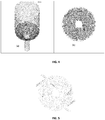
- the Figure 4 (4A: isometric view, 4B: view from above) shows for the non-injection (comparative) configuration, the parts of the equipment where the volume fraction of the solid phase is greater than 0.1% by volume. These areas represent areas of solid particle accumulation.
- the Figure 5 present for the configuration with injections according to the invention, the parts of the equipment where the volume fraction of the solid phase is greater than 0.1% by volume, seen from above.
Landscapes
- Chemical & Material Sciences (AREA)
- Oil, Petroleum & Natural Gas (AREA)
- Chemical Kinetics & Catalysis (AREA)
- Organic Chemistry (AREA)
- Engineering & Computer Science (AREA)
- General Chemical & Material Sciences (AREA)
- Physics & Mathematics (AREA)
- Thermal Sciences (AREA)
- Combustion & Propulsion (AREA)
- Production Of Liquid Hydrocarbon Mixture For Refining Petroleum (AREA)
Abstract
Description
- L'invention concerne le domaine de la réduction des dépôts de sédiments ou de molécules instables ou insolubles dans les équipements de séparation et de distillation préférentiellement à fond conique, qui sont mis en oeuvre en aval des procédés de raffinage traitant des produits lourds ou encrassants. L'invention s'applique de façon non exhaustive aux procédés produisant des liquides susceptibles d'encrasser les équipements, comme la viscoréduction, l'hydrocraquage en lit bouillonnant, le craquage catalytique, la cokéfaction retardée en raffinage de produits pétroliers ainsi que les procédés de liquéfaction de charbon et de traitement de biomasse.
- La réduction des dépôts encrassant les équipements est une problématique majeure dans les unités de traitement ou conversion des charges hydrocarbonées, notamment pour les charges lourdes. En effet, l'encrassement des équipements impose l'arrêt de l'unité et son démontage pour effectuer le nettoyage. Dans les unités de conversion de charges hydrocarbonées en lit bouillonnant, notamment, l'encrassement des parois et du fond des équipements de séparation peut être dû à des particules de nature asphalténique qui floculent pour former des dépôts solides, des molécules qui s'adsorbent à la paroi, des particules de coke, des fines de catalyseurs, des sulfures métalliques à base de nickel, fer et/ou vanadium ou plus généralement tout solide contenu dans la charge hydrocarbonée traitée.
- La demande de brevet
US4534851A décrit une méthode d'introduction d'une charge liquide hydrocarbonée dans une conduite de transfert vers une zone réactionnelle, comprenant une injection de vapeur et de la charge hydrocarbonée en écoulement ascendant avec des flux concentriques séparés, le flux de charge hydrocarbonée étant le flux interne et le flux de vapeur étant le flux circonférentiel, et la direction d'une partie de la vapeur vers la paroi interne de ladite conduite de transfert, tandis que le reste de la vapeur et de la charge hydrocarbonée sont évacués de la zone dans une direction parallèle à l'axe longitudinal. Cependant cette demande ne décrit pas de dispositif permettant la réduction des zones stagnantes par le recyclage du liquide hydrocarboné ou un appoint de liquide externe à la fois à l'intérieur de la partie tronconique et/ou à l'intérieur de la partie cylindrique de l'équipement. - L'invention concerne un dispositif pour l'écoulement descendant d'un liquide hydrocarboné contenant des particules solides en fond d'un équipement (1) comprenant une partie supérieure cylindrique (11) de diamètre D1, une partie inférieure tronconique (12) d'angle d'inclinaison α compris entre 5° et 85°par rapport à l'axe vertical (z) de ladite partie supérieure cylindrique, une conduite de sortie (9) de diamètre D2, caractérisé en ce qu'il comprend :
- au moins une injection (5) de liquide recyclé et/ou d'appoint dans la partie tronconique (12) de l'équipement (1) ;
- au moins une injection (6) de liquide recyclé et/ou d'appoint dans la partie cylindrique (11) de l'équipement (1) ;
- Avantageusement, le dispositif selon l'invention comprend une conduite de recyclage (4) d'une partie du liquide sortant de ladite conduite de sortie (9), ladite conduite de recyclage (4) alimentant en liquide recyclé au moins une desdites injections (5) ou (6).
- Le dispositif selon l'invention peut comprendre une conduite d'appoint (10) pour alimenter en liquide d'appoint au moins une desdites injections (5) ou (6).
- Lesdites injections peuvent être réparties par couches horizontales (7) dans la partie tronconique et par couches horizontales (8) dans la partie cylindrique respectivement.
- Avantageusement, le rapport entre le diamètre D1 de la partie cylindrique et le diamètre D2 de la conduite de sortie en fond de la partie tronconique (D1/D2) est compris entre 1,1 et 1000, de préférence entre 2 et 500 et de manière préférée entre 3 et 100.
- Avantageusement, l'angle α est compris entre 10° et 70°, de préférence entre 15° et 60° et de manière très préférée entre 30° et 50°.
- De préférence, les angles β1 et θ1 sont compris entre 10° et 150°, de manière très préférée entre 15° et 120°, de manière plus préférée entre 15° et 90°et de manière encore plus préférée entre 20° et 60°.
- De préférence, les angles β2 et θ2 sont compris entre 90° et 180°.
- De manière très préférée, les angles β2 et θ2 sont égaux à 90°.
- Avantageusement, le diamètre D1 est compris entre 0,1 m et 30 m, de préférence entre 0,5 m et 20 m, et de manière très préférée entre 1 m et 10 m.
- Avantageusement, la hauteur H entre deux couches horizontales est comprise entre 0,01 m et 10 m, de préférence entre 0,05 m et 5 m et de manière très préférée entre 0,1 m et 1 m.
- De préférence, le nombre d'injections N par couche est compris entre 1 et 30.
- De préférence, le nombre d'injections par couche est compris entre 2 et 20, lesdites injections au sein d'une même couche étant espacées d'un angle δ égal à 360/N où N désigne le nombre d'injections par couche.
- De manière très préférée, le nombre d'injections par couche est compris entre 2 et 10, de manière encore plus préférée entre 2 et 6.
- De préférence, l'équipement (1) est un moyen de séparation gaz/liquide permettant de traiter des charges hydrocarbonées.
- L'invention concerne également un procédé de conversion de charges hydrocarbonées mettant en oeuvre ledit dispositif .
- De préférence, ledit procédé met en oeuvre une étape d'hydroconversion en lit bouillonnant pour des charges contenant des fractions d'hydrocarbures dont au moins 50 % poids ont une température d'ébullition supérieure à 300°C.
- La vitesse du liquide V injecté dans lesdites injections est comprise avantageusement entre 0,05 m.s-1 et 40 m.s-1, de préférence entre 0,1 m.s-1 et 30 m.s-1 et de manière très préférée entre 0,5 m.s-1 et 10 m.s-1.
- Le taux d'injection de liquide injecté par les injections (5) et (6) par rapport au liquide circulant dans l'équipement (1) est avantageusement compris entre 1% et 400%, de préférence entre 5% et 100%, de manière très préférée entre 10% et 60% et de manière encore plus préférée entre 20 et 50%.
- D'autres caractéristiques et avantages du dispositif selon l'invention, apparaîtront à la lecture de la description ci-après d'exemples non limitatifs de réalisations, en se référant aux figures annexées et décrites ci-après.
-
Figure 1 : Lafigure 1 représente le schéma de principe du dispositif selon l'invention. -
Figure 2 : Lafigure 2 illustre la mise en oeuvre des injections de liquide hydrocarboné recyclé et/ou d'appoint à l'intérieur des parties cylindrique et tronconique de l'équipement. -
Figure 3 : Lafigure 3 illustre le dispositif selon l'invention et la mise en oeuvre d'injections latérales multiples de liquide dans les parties cylindrique et tronconique de l'équipement - Vue de face et vue de haut : (3A) injections multiples (6) dans la partie cylindrique de l'équipement 1 ; (3B) injections multiples (5) dans la partie tronconique de l'équipement 1 -
Figure 4 : LaFigure 4 (4A : vue isométrique, 4B : vue de haut) présente pour la configuration sans injection, les parties de l'équipement où la fraction volumique de la phase solide est supérieure à 0,1 % en volume. Ces zones montrent les zones d'accumulation de particules solides. -
Figure 5 : LaFigure 5 présente pour la configuration avec injections, les parties de l'équipement où la fraction volumique de la phase solide est supérieure à 0,1 % en volume. - De manière générale, l'invention s'applique à tout équipement dans lequel circule un liquide hydrocarboné avec possibilité de stagnation et accumulation de particules solides en fond d'équipement. Plus particulièrement, le dispositif selon l'invention est situé dans la partie inférieure d'une colonne de distillation atmosphérique ou sous vide, ballon de séparation ou tout autre moyen de séparation gaz/liquide permettant de traiter des charges hydrocarbonées.
- Dans la suite du texte, on désigne par « injection » tout moyen connu de l'homme du métier permettant d'injecter du liquide depuis la paroi de l'équipement vers l'intérieur, ledit moyen étant alimenté par au moins une conduite de transport de liquide.
- La
Figure 1 présente le schéma de principe de l'invention. - L'invention est mise en oeuvre dans un équipement (1) à fond conique, c'est-à-dire comprenant une partie supérieure cylindrique (11) et une partie inférieure tronconique (12) où un liquide hydrocarboné (2) encrassant (c'est-à-dire un liquide contenant des particules solides ou des composés susceptibles de floculer ou de s'adsorber à la paroi) s'écoule de manière descendante à partir du haut de l'équipement et sort à travers une conduite de sortie (9). La forme tronconique est bien connue de l'homme du métier pour minimiser le dépôt dans le fond en facilitant le drainage des solides par gravité vers la conduite de sortie. Afin de réduire la formation des dépôts en paroi et dans le fond de l'équipement, le dispositif comprend des injections latérales de liquide recyclé et/ou d'appoint : injections dans la partie tronconique (5) et injections dans la partie cylindrique (6). Ces injections peuvent être réparties à la paroi selon des couches horizontales dans la partie tronconique (7) et selon des couches horizontales dans la partie cylindrique (8). Le flux liquide sortant est évacué de l'équipement par une conduite d'évacuation (3).
- Dans un premier mode de réalisation de l'invention, une conduite d'appoint de liquide (qui peut être un liquide fluxant) (10) alimente les injections latérales (5) et (6) situées dans la partie tronconique et dans la partie cylindrique, afin de réduire les zones stagnantes dans l'équipement (1) et de limiter les dépôts de particules solides sur les parois. Toute coupe de point d'ébullition supérieur ou égal au point d'ébullition du liquide hydrocarboné alimentant l'équipement (1), par exemple effluent de craquage catalytique (HCO), LCO, ou toute autre coupe VGO, AR, VR, DAO, extrait aromatique peut convenir comme liquide d'appoint. Selon ce mode de réalisation le débit de liquide sortant par la conduite d'évacuation (3) est égal à somme du débit de liquide hydrocarboné circulant dans l'équipement (2) et du débit de liquide d'appoint injecté dans la conduite d'appoint (10). Le liquide d'appoint injecté à travers la conduite d'appoint (10) permet de réduire les zones stagnantes en générant une turbulence dans l'équipement (1) afin de limiter les dépôts de particules solides sur les parois. Ledit liquide d'appoint injecté peut également jouer un rôle de fluxant lorsque le liquide choisi est une base aromatique.
- Selon un autre mode de réalisation de l'invention, une partie du liquide hydrocarboné sortant de l'équipement (1) peut être recyclée pour alimenter les injections latérales (5) et (6). Selon ce mode de réalisation le débit de liquide sortant par la conduite d'évacuation (3) est égal au débit du liquide (2). Le liquide recyclé à travers la conduite de recyclage (4) permet de réduire les zones stagnantes dans l'équipement (1) en générant une turbulence afin de limiter les dépôts de particules solides sur les parois.
- Selon un dernier mode de réalisation de l'invention, le liquide injecté dans les injections latérales (5) et (6) peut provenir à la fois de la conduite de recyclage (4) et de la conduite d'appoint de liquide (10). Selon ce mode de réalisation, le débit de liquide sortant par la conduite d'évacuation (3) est égal à la somme du débit de liquide hydrocarboné circulant dans l'équipement, dit liquide encrassant (2), et du débit de liquide d'appoint injecté dans la conduite d'appoint (10). Le liquide injecté à travers la conduite d'appoint (10) et à travers la conduite de recyclage (4) permet de réduire les zones stagnantes en générant une turbulence dans l'équipement (1) afin de limiter les dépôts de particules solides sur les parois et peut également jouer le rôle de fluxant évoqué précédemment.
- Le liquide injecté par les injections latérales (5) et (6) peut donc être du liquide recyclé depuis l'équipement (1) et/ou du liquide d'appoint, c'est-à-dire un liquide provenant de l'extérieur de l'équipement (1).
- On définit le taux d'injection du liquide injecté par les injections latérales (5) et (6) comme étant le rapport entre la somme du débit de liquide dans la conduite de recyclage (4) et du débit de liquide dans la conduite d'appoint (10) sur le débit de liquide hydrocarboné circulant dans l'équipement ou liquide encrassant (2).
- La charge entrant dans le dispositif peut contenir tout type de composés issus d'un effluent d'un procédé d'hydroconversion, par exemple issu d'une unité lit bouillonnant H-OIL ™, mais également tout type de composés issus d'un procédé d'hydroconversion en slurry, d'un procédé d'hydrotraitement en lit fixe, lit mobile, lit fluidisé, effluent de craquage catalytique (FCC), effluents des procédés de conversion thermique comme le coking, le visbreaking, et tout autre procédé de séparation comme par exemple le désasphaltage au solvant.
- Les particules solides peuvent être des asphaltènes précipités, des fines de catalyseurs supportés ou non supportés (usuellement de diamètre inférieur à 500 microns) ou des particules de coke, des sulfures de métaux tels que nickel, vanadium, fer, molybdène.
- L'écoulement dans le dispositif se fait de manière descendante, le dispositif selon l'invention peut être mis en oeuvre en fond de colonne de distillation sous vide ou en fond de colonne atmosphérique ou en fond de tout séparateur gaz-liquide.
- La
Figure 2 présente les différents types d'injections latérales de la partie recyclée du liquide ou du liquide d'appoint. - L'équipement 1, qui peut être par exemple une colonne de distillation ou un séparateur, possède une partie supérieure cylindrique (11) de diamètre D1, une partie inférieure tronconique (12), une conduite de sortie (9) située en bas de l'équipement, par laquelle le liquide hydrocarboné sort, de diamètre D2. La partie tronconique (12) (aussi appelée fond conique) a un angle d'inclinaison α, par rapport à la paroi verticale de la partie cylindrique, matérialisée par l'axe z. Deux types d'injection de liquide (d'appoint ou recyclé) sont définis :
- Les injections (5) dans la partie tronconique de l'équipement (1).

- Les injections (6) dans la partie cylindrique de l'équipement (1).

- Les injections (5) situées dans la partie tronconique (12) sont inclinées par rapport à la paroi du fond conique d'un angle β1 dans le plan vertical (xz) et d'un angle β2 dans le plan horizontal (xy), x désigne l'axe horizontal, z désigne l'axe vertical de la partie cylindrique perpendiculaire au plan horizontal (xy).
- Les injections (6) situées dans la partie cylindrique (11) sont inclinées par rapport à la paroi du corps cylindrique d'un angle θ1 dans le plan vertical (xz) et d'un angle θ2 dans le plan horizontal (xy).
- Les injections sont avantageusement orientées dans le même sens de rotation dans le plan horizontal (xy) et situées avantageusement dans la partie liquide du fond de colonne.
- La
Figure 3A présente la mise en oeuvre multiple d'injections (6) dans la partie cylindrique (11) de l'équipement (1), laFigure 3B présente la mise en oeuvre multiple d'injections (5) dans la partie tronconique (12) de l'équipement (1). - La mise en place des injections à la paroi de l'équipement est effectuée suivant des couches horizontales (8) dans le plan (xy) pour les injections (6) dans la partie cylindrique (11) et suivant des couches horizontales (7) pour les injections (5) dans la partie tronconique (12). Chaque couche d'injections (7) dans la partie tronconique (12) et (8) dans la partie cylindrique (11) comprend respectivement un nombre N d'injections (5) ou (6) localisées à la même hauteur sur l'axe (z). Sur la
Figure 3 , N est égal à 2. Chaque couche est séparée par une hauteur H. A l'intérieur d'une couche, chaque injection est séparée de la suivante par un angle δ égal à 360/N dans le plan (xy). Comme montré sur laFigure 3 , une couche d'injections peut être décalée par rapport à une autre couche d'injections d'un angle γ dans le plan (xy). - Le nombre de couches dans chacune des parties tronconique ou cylindrique est avantageusement compris entre 1 et 20, de préférence entre 1 et 10 et de manière préférée entre 1 et 6.
- La vitesse du liquide V injecté dans les conduites d'injections latérales (5) et (6) est comprise avantageusement entre 0,05 m.s-1 et 40 m.s-1, de préférence entre 0,1 m.s-1 et 30 m.s-1 et de manière très préférée entre 0,5 m.s-1 et 10 m.s-1. De manière préférée, les diamètres des conduites d'injection sont dimensionnés en fonction du débit de liquide à injecter afin d'obtenir les vitesses d'injection souhaitées.
- Le débit de liquide recyclé par la conduite de recyclage (4) plus le débit de liquide injecté par la conduite (10) sur le débit de liquide hydrocarboné (2) circulant dans l'équipement (1) est avantageusement compris entre 1% et 400%, de préférence entre 5% et 100%, de manière très préférée entre 10% et 60% et de manière encore plus préférée entre 20 et 50%.
- Le diamètre D1 de la partie cylindrique (11) de l'équipement (1) est avantageusement compris entre 0,1 m et 30 m, de préférence entre 0,5 m et 20 m, et de manière très préférée entre 1 m et 10 m.
- Le rapport entre le diamètre D1 de la partie cylindrique (11) et le diamètre D2 de la conduite de sortie (9) en fond de la partie tronconique (D1/D2) est avantageusement compris entre 1,1 et 1000, de préférence entre 2 et 500 et de manière préférée entre 3 et 100.
- L'angle α est l'angle d'inclinaison de la partie tronconique par rapport à la paroi verticale (d'axe z) de la partie cylindrique et est compris de manière avantageuse entre 5° et 85°, de préférence entre 10 et 70°, de manière très préférée entre 15 et 60° et de manière encore plus préférée entre 30 et 50°.
- Les angles β1 et θ1 sont compris entre 5° et 175° par rapport respectivement à la paroi de la partie tronconique et à la paroi de la partie cylindrique, de préférence entre 10° et 150°, de manière très préférée entre 15° et 120° et de manière plus préférée entre 15° et 90° et de manière encore plus préférée entre 20° et 60°.
- Les angles β2 et θ2 sont compris entre 90° et 270° par rapport au diamètre selon l'axe y de la section cylindrique, et de manière préférée entre 90° et 180°. De manière très préférée, les angles β2 et θ2 sont égaux à 90°.
- Le nombre d'injections N à la paroi de l'équipement, dans chaque couche horizontale (8) dans la partie cylindrique (11) et dans chaque couche horizontale (7) dans la partie tronconique (12) est compris entre 1 et 30, de préférence entre 2 et 20, de manière très préférée entre 2 et 10, de manière plus préférée entre 2 et 6. Chaque couche, que ce soit au sein d'une même partie ou dans les deux parties, peut avoir un nombre d'injections N différent.
- La hauteur H entre deux couches est avantageusement comprise entre 0,01 m et 10 m, de préférence entre 0,05 m et 5 m et de manière très préférée entre 0,1 m et 1 m.
- L'angle δ séparant les injections dans la circonférence d'une même couche est compris entre 0° et 180°, de préférence entre 5° et 120°, de manière très préférée entre 10° et 90°. De manière avantageuse, l'angle δ est égal à 360/N où N désigne le nombre d'injections par couche.
- L'angle γ désigne le décalage angulaire d'une couche par rapport à l'autre. Cet angle peut être compris entre 0° et 180°, de préférence entre 5° et 120°, de manière très préférée entre 10° et 90°.
- Des simulations en mécanique des fluides numérique CFD (en anglais « Computational Fluid Dynamics ») de l'écoulement liquide/particules dans un équipement à fond conique sans injections (comparatif) et dans le même équipement à fond conique comprenant un dispositif avec des injections latérales de liquide recyclé selon l'invention ont été effectuées avec le logiciel Barracuda™. Ce logiciel utilise une approche Eulérienne pour la phase fluide et une approche pseudo-lagrangienne pour la phase particulaire (voir publication D.M. Snider, An Incompressible Three-Dimensional Multiphase Particle-in-Cell Model for Dense Particle Flows, Journal of Computational Physics 170 (2001), 523-549).
- Le tableau 1 présente les conditions simulées, ainsi que les caractéristiques et dimensions de l'équipement, incluant le dispositif selon l'invention (nombre d'injections, nombre de couches, angles d'injection).
Tableau 1 Dimensions équipements Diamètre D1 (m) 1,2 Diamètre D2 (m) 0,25 Angle α 45° Nombre de couches dans la partie cylindrique 1 Nombre de couches dans la partie tronconique 1 Nombre d'injections par couche 2 Angle β1 et θ1 30° Angle β2 et θ2 90° Conditions opératoires Masse volumique liquide hydrocarboné (2) (kg/m3) 990 Débit liquide hydrocarboné circulant (2) (kg/s) 7,5 Taux d'injection (débit du liquide recyclé dans la conduite (4) sur débit liquide hydrocarboné circulant (2)) 30% Masse volumique particules solides (kg/m3) 2800 Diamètre particules solides (microns) 50 Débit particules solides (kg/s) 0,02 - La
Figure 4 (4A : vue isométrique, 4B : vue de haut) présente pour la configuration sans injection (comparatif), les parties de l'équipement où la fraction volumique de la phase solide est supérieure à 0,1 % en volume. Ces zones représentent les zones d'accumulation de particules solides. - La
Figure 5 présente pour la configuration avec injections selon l'invention, les parties de l'équipement où la fraction volumique de la phase solide est supérieure à 0,1 % en volume, en vue de dessus. - En comparant la
figure 4B et lafigure 5 , on observe la diminution des zones d'accumulation de solide grâce à la mise en place des injections latérales de liquide avec le dispositif selon l'invention. Par un calcul volumique, il apparaît que dans la configuration selon l'invention, avec un recyclage de 30% du liquide hydrocarboné pour alimenter deux injections en partie tronconique et deux injections en partie cylindrique avec une géométrie conforme à l'invention, le nombre de zones d'accumulation telles que définies précédemment a été divisé par 30.
Claims (19)
- Dispositif pour l'écoulement descendant d'un liquide hydrocarboné contenant des particules solides en fond d'un équipement (1) comprenant une partie supérieure cylindrique (11) de diamètre D1, une partie inférieure tronconique (12) d'angle d'inclinaison α compris entre 5° et 85° par rapport à l'axe vertical (z) de ladite partie supérieure cylindrique, une conduite de sortie (9) de diamètre D2, caractérisé en ce qu'il comprend :- au moins une injection (5) de liquide recyclé et/ou d'appoint dans la partie tronconique (12) de l'équipement (1) ;- au moins une injection (6) de liquide recyclé et/ou d'appoint dans la partie cylindrique (11) de l'équipement (1) ;la ou lesdites injections (5) situées dans ladite partie tronconique étant inclinées par rapport à la paroi de la partie inférieure tronconique d'un angle β1 dans le plan vertical (xz) et d'un angle β2 dans le plan horizontal (xy) ; la ou lesdites injections (6) situées dans ladite partie cylindrique étant inclinées par rapport à la paroi de la partie supérieure cylindrique d'un angle θ1 dans le plan vertical (xz) et d'un angle θ2 dans le plan horizontal (xy), les angles β1 et θ1 étant compris entre 5° et 175°, les angles β2 et θ2 étant compris entre 90° et 270°.
- Dispositif selon la revendication 1 comprenant une conduite de recyclage (4) d'une partie du liquide sortant de ladite conduite de sortie (9), ladite conduite de recyclage (4) alimentant en liquide recyclé au moins une desdites injections (5) ou (6).
- Dispositif selon l'une des revendications 1 ou 2 comprenant une conduite d'appoint (10) pour alimenter en liquide d'appoint au moins une desdites injections (5) ou (6).
- Dispositif selon l'une des revendications précédentes dans lequel lesdites injections sont réparties par couches horizontales (7) dans la partie tronconique et par couches horizontales (8) dans la partie cylindrique respectivement.
- Dispositif selon l'une des revendications précédentes dans lequel le rapport entre le diamètre D1 de la partie cylindrique et le diamètre D2 de la conduite de sortie en fond de la partie tronconique (D1/D2) est compris entre 1,1 et 1000, de préférence entre 2 et 500 et de manière préférée entre 3 et 100.
- Dispositif selon l'une des revendications précédentes dans lequel l'angle α est compris entre 10° et 70°, de préférence entre 15° et 60° et de manière très préférée entre 30° et 50°.
- Dispositif selon l'une des revendications précédentes dans lequel les angles β1 et θ1 sont compris entre 10° et 150°, de manière très préférée entre 15° et 120°, de manière plus préférée entre 15° et 90° et de manière encore plus préférée entre 20° et 60°.
- Dispositif selon l'une des revendications précédentes dans lequel les angles β2 et θ2 sont compris entre 90° et 180°.
- Dispositif selon la revendication 8 dans lequel les angles β2 et θ2 sont égaux à 90°.
- Dispositif selon l'une des revendications 1 à 9 dans lequel le diamètre D1 est compris entre 0,1 m et 30 m, de préférence entre 0,5 m et 20 m, et de manière très préférée entre 1 m et 10 m.
- Dispositif selon l'une des revendications 4 à 10 dans lequel la hauteur H entre deux couches horizontales est comprise entre 0,01 m et 10 m, de préférence entre 0,05 m et 5 m et de manière très préférée entre 0,1 m et 1 m.
- Dispositif selon l'une des revendications 4 à 11 dans lequel le nombre d'injections N par couche est compris entre 1 et 30.
- Dispositif selon la revendication 12 dans lequel le nombre d'injections par couche est compris entre 2 et 20, lesdites injections au sein d'une même couche étant espacées d'un angle δ égal à 360/N où N désigne le nombre d'injections par couche.
- Dispositif selon la revendication 13 dans lequel le nombre d'injections par couche est compris entre 2 et 10, de préférence entre 2 et 6.
- Dispositif selon l'une des revendications précédentes dans lequel ledit équipement est un moyen de séparation gaz/liquide permettant de traiter des charges hydrocarbonées.
- Procédé de conversion de charges hydrocarbonées mettant en oeuvre un dispositif selon l'une des revendications 1 à 15.
- Procédé selon la revendication 16 mettant en oeuvre une étape d'hydroconversion en lit bouillonnant pour des charges contenant des fractions d'hydrocarbures dont au moins 50 % poids ont une température d'ébullition supérieure à 300°C.
- Procédé selon l'une des revendications 16 ou 17 dans lequel la vitesse du liquide V injecté dans lesdites injections est comprise entre 0,05 m.s-1 et 40 m.s-1, de préférence entre 0,1 m.s-1 et 30 m.s-1 et de manière très préférée entre 0,5 m.s-1 et 10 m.s-1.
- Procédé selon l'une des revendications 16 à 18 dans lequel le taux d'injection de liquide recyclé et/ou d'appoint par rapport au liquide hydrocarboné circulant dans l'équipement est compris entre 1% et 400%, de préférence entre 5% et 100%, de manière très préférée entre 10% et 60% et de manière encore plus préférée entre 20 et 50%.
Applications Claiming Priority (1)
| Application Number | Priority Date | Filing Date | Title |
|---|---|---|---|
| FR1759606A FR3072302B1 (fr) | 2017-10-13 | 2017-10-13 | Dispositif comprenant des injections laterales de liquide pour limiter les phenomenes de depots solides dans les equipements a fond conique |
Publications (2)
| Publication Number | Publication Date |
|---|---|
| EP3470137A1 true EP3470137A1 (fr) | 2019-04-17 |
| EP3470137B1 EP3470137B1 (fr) | 2024-04-10 |
Family
ID=61003125
Family Applications (1)
| Application Number | Title | Priority Date | Filing Date |
|---|---|---|---|
| EP18199193.6A Active EP3470137B1 (fr) | 2017-10-13 | 2018-10-08 | Procédé de conversion de charges hydrocarbonées mettant en oeuvre un dispositif comprenant des injections latérales de liquide pour limiter les phénomènes de dépôts solides dans les équipements a fond conique |
Country Status (11)
| Country | Link |
|---|---|
| US (2) | US20190112536A1 (fr) |
| EP (1) | EP3470137B1 (fr) |
| CN (1) | CN109663547B (fr) |
| BR (1) | BR102018070766B1 (fr) |
| ES (1) | ES2981996T3 (fr) |
| FI (1) | FI3470137T3 (fr) |
| FR (1) | FR3072302B1 (fr) |
| MX (1) | MX2018012355A (fr) |
| PL (1) | PL3470137T3 (fr) |
| PT (1) | PT3470137T (fr) |
| RU (1) | RU2771035C2 (fr) |
Families Citing this family (2)
| Publication number | Priority date | Publication date | Assignee | Title |
|---|---|---|---|---|
| EP3831472A1 (fr) * | 2019-12-03 | 2021-06-09 | Basell Polyolefine GmbH | Système de polymérisation haute pression et procédé de polymérisation à haute pression pour la polymérisation de monomères éthyléniquement insaturés |
| FR3110888B1 (fr) * | 2020-05-29 | 2023-05-19 | Ifp Energies Now | Système de propulsion électrique amovible pour un objet roulant avec un moyen de préhension et de levage combinés et simultanés |
Citations (4)
| Publication number | Priority date | Publication date | Assignee | Title |
|---|---|---|---|---|
| US3846079A (en) * | 1970-05-19 | 1974-11-05 | Inst Francais Du Petrole | Vertical reaction vessel for effecting reaction of liquid and gaseous reactants by liquid-gas contact |
| US4146359A (en) * | 1976-06-25 | 1979-03-27 | Occidental Petroleum Corporation | Method for reacting nongaseous material with a gaseous reactant |
| US6238912B1 (en) * | 1995-07-15 | 2001-05-29 | Philip Coley Moore | Method and apparatus for contacting gas and liquid |
| US20160346758A1 (en) * | 2015-06-01 | 2016-12-01 | Cetamax Ventures Ltd. | Systems and methods for processing fluids |
Family Cites Families (15)
| Publication number | Priority date | Publication date | Assignee | Title |
|---|---|---|---|---|
| JPS538721B2 (fr) * | 1972-04-07 | 1978-03-31 | ||
| US4615792A (en) * | 1985-04-25 | 1986-10-07 | Uop Inc. | Hydrogen circulation for moving bed catalyst transfer systems |
| US10188119B2 (en) * | 2001-07-16 | 2019-01-29 | Foret Plasma Labs, Llc | Method for treating a substance with wave energy from plasma and an electrical arc |
| US7416571B2 (en) * | 2005-03-09 | 2008-08-26 | Conocophillips Company | Compact mixer for the mixing of gaseous hydrocarbon and gaseous oxidants |
| CN202654922U (zh) * | 2012-04-10 | 2013-01-09 | 河北国惠环保科技有限公司 | 一种防止塔底固体悬浮物沉积的烟气脱硫塔 |
| US9382359B2 (en) * | 2012-08-29 | 2016-07-05 | Borealis Ag | Reactor assembly and method for polymerization of olefins |
| WO2014117725A1 (fr) * | 2013-01-31 | 2014-08-07 | Shanghai Advanced Research Institute, Chinese Academy Of Sciences | Réacteur à combustible en suspension et procédé d'utilisation associé |
| CN105934447B (zh) * | 2013-11-29 | 2019-02-01 | 沙特基础工业公司 | 用于在反应器中的烯烃单体的连续聚合的方法 |
| EP3074434B1 (fr) * | 2013-11-29 | 2018-05-23 | Saudi Basic Industries Corporation | Réacteur à zones multiples pour polymérisation continue de monomères oléfiniques |
| US9975968B2 (en) * | 2013-11-29 | 2018-05-22 | Sabic Global Technologies B.V. | Process for continuous polymerization of olefin monomers in a reactor |
| US20190210042A1 (en) * | 2014-07-09 | 2019-07-11 | Sudhin Biopharma | Particle setting devices |
| US10596492B2 (en) * | 2014-07-09 | 2020-03-24 | Sudhin Biopharma | Particle settling devices |
| EP3331924B1 (fr) * | 2015-08-07 | 2019-08-21 | SABIC Global Technologies B.V. | Procédé pour la polymérisation d'oléfines |
| US11103848B2 (en) * | 2016-08-15 | 2021-08-31 | Advanced Energy Materials, Llc | Flame based fluidized bed reactor for nanomaterials production |
| CN106841661B (zh) * | 2017-01-12 | 2019-08-09 | 中国科学院工程热物理研究所 | 一种示踪粒子发生器 |
-
2017
- 2017-10-13 FR FR1759606A patent/FR3072302B1/fr active Active
-
2018
- 2018-10-08 RU RU2018135293A patent/RU2771035C2/ru active
- 2018-10-08 PL PL18199193.6T patent/PL3470137T3/pl unknown
- 2018-10-08 ES ES18199193T patent/ES2981996T3/es active Active
- 2018-10-08 FI FIEP18199193.6T patent/FI3470137T3/fi active
- 2018-10-08 PT PT181991936T patent/PT3470137T/pt unknown
- 2018-10-08 EP EP18199193.6A patent/EP3470137B1/fr active Active
- 2018-10-09 BR BR102018070766-3A patent/BR102018070766B1/pt active IP Right Grant
- 2018-10-09 MX MX2018012355A patent/MX2018012355A/es unknown
- 2018-10-12 US US16/158,414 patent/US20190112536A1/en not_active Abandoned
- 2018-10-12 CN CN201811189527.8A patent/CN109663547B/zh active Active
-
2020
- 2020-12-15 US US17/121,977 patent/US11549074B2/en active Active
Patent Citations (4)
| Publication number | Priority date | Publication date | Assignee | Title |
|---|---|---|---|---|
| US3846079A (en) * | 1970-05-19 | 1974-11-05 | Inst Francais Du Petrole | Vertical reaction vessel for effecting reaction of liquid and gaseous reactants by liquid-gas contact |
| US4146359A (en) * | 1976-06-25 | 1979-03-27 | Occidental Petroleum Corporation | Method for reacting nongaseous material with a gaseous reactant |
| US6238912B1 (en) * | 1995-07-15 | 2001-05-29 | Philip Coley Moore | Method and apparatus for contacting gas and liquid |
| US20160346758A1 (en) * | 2015-06-01 | 2016-12-01 | Cetamax Ventures Ltd. | Systems and methods for processing fluids |
Also Published As
| Publication number | Publication date |
|---|---|
| BR102018070766A2 (pt) | 2019-09-17 |
| EP3470137B1 (fr) | 2024-04-10 |
| MX2018012355A (es) | 2019-06-24 |
| CN109663547A (zh) | 2019-04-23 |
| CN109663547B (zh) | 2022-07-08 |
| RU2018135293A3 (fr) | 2021-11-22 |
| FR3072302B1 (fr) | 2022-04-01 |
| US11549074B2 (en) | 2023-01-10 |
| ES2981996T3 (es) | 2024-10-14 |
| FI3470137T3 (fi) | 2024-07-02 |
| PT3470137T (pt) | 2024-07-04 |
| PL3470137T3 (pl) | 2024-10-14 |
| FR3072302A1 (fr) | 2019-04-19 |
| RU2018135293A (ru) | 2020-04-08 |
| BR102018070766B1 (pt) | 2022-12-13 |
| US20210095214A1 (en) | 2021-04-01 |
| RU2771035C2 (ru) | 2022-04-25 |
| US20190112536A1 (en) | 2019-04-18 |
Similar Documents
| Publication | Publication Date | Title |
|---|---|---|
| WO2021058289A1 (fr) | Procédé intégré d'hydrocraquage en lit fixe et d'hydroconversion en lit bouillonnant avec une séparation gaz/liquide améliorée | |
| EP3077483B1 (fr) | Procede de conversion d'une charge hydrocarbonee lourde integrant un desasphaltage selectif en cascade avec recyclage d'une coupe desasphaltee | |
| WO2016146326A1 (fr) | Procede ameliore de conversion de charges hydrocarbonnees lourdes | |
| EP2209873B1 (fr) | Procede d' hydroconversion de charges lourdes en lit bouillonnant avec injection de la charge en tete de reacteur | |
| EP1170355B1 (fr) | Procédé et dispositif de craquage d'hydrocarbures mettant en oeuvre deux chambres réactionelles successives | |
| EP3470137B1 (fr) | Procédé de conversion de charges hydrocarbonées mettant en oeuvre un dispositif comprenant des injections latérales de liquide pour limiter les phénomènes de dépôts solides dans les équipements a fond conique | |
| EP3538627B1 (fr) | Nouveau dispositif de separation gaz liquide pour equiper les reacteurs en lit fluidise triphasique tels que ceux utilises dans le procede h-oil | |
| WO2014096591A1 (fr) | Procede de conversion d'une charge hydrocarbonee lourde integrant un desasphaltage selectif avec recycle de l'huile desasphaltee | |
| EP3721962A1 (fr) | Réacteur triphasique avec coupelle de recyclé de section décroissante et d'angle d'inclinaison variable | |
| EP3569677B1 (fr) | Dispositif limitateur de vortex et de depots solides | |
| EP3693083B1 (fr) | Procede mettant en oeuvre une enceinte comprenant un fond de section decroissante et d'angle d'inclinaison variable avec des injections laterales de liquide pour limiter l'encrassement | |
| WO2020207821A1 (fr) | Reacteur triphasique avec coupelle de recycle tronconique a fort angle d'inclinaison | |
| FR3084371A1 (fr) | Procede de traitement d'une charge hydrocarbonee lourde comprenant un hydrotraitement en lit fixe, un desasphaltage et un hydrocraquage en lit bouillonnant de l'asphalte | |
| CA2458410A1 (fr) | Procede et installation de traitement d'hydrocarbures et de separation des phases produites par ledit traitement | |
| FR3080628A1 (fr) | Procede d'hydrocraquage de charges hydrocarbonees. | |
| FR3075069A1 (fr) | Reacteur a lit bouillonnant compartimente verticalement et procede d’hydroconversion de charges petrolieres lourdes | |
| FR3100992A1 (fr) | Séparateur gaz/liquide haute pression et procédé de séparation mettant en œuvre un tel séparateur | |
| FR3075070A1 (fr) | Reacteur a lit bouillonnant compartimente et procede d’hydroconversion de charges petrolieres lourdes | |
| FR3097139A1 (fr) | Reacteur triphasique a compartiments verticaux en serie avec separateurs intermediaires et procede d’hydroconversion de charges petrolieres lourdes | |
| FR3097138A1 (fr) | Reacteur triphasique a compartiments verticaux en serie et procede d’hydroconversion de charges petrolieres lourdes |
Legal Events
| Date | Code | Title | Description |
|---|---|---|---|
| PUAI | Public reference made under article 153(3) epc to a published international application that has entered the european phase |
Free format text: ORIGINAL CODE: 0009012 |
|
| STAA | Information on the status of an ep patent application or granted ep patent |
Free format text: STATUS: THE APPLICATION HAS BEEN PUBLISHED |
|
| AK | Designated contracting states |
Kind code of ref document: A1 Designated state(s): AL AT BE BG CH CY CZ DE DK EE ES FI FR GB GR HR HU IE IS IT LI LT LU LV MC MK MT NL NO PL PT RO RS SE SI SK SM TR |
|
| AX | Request for extension of the european patent |
Extension state: BA ME |
|
| STAA | Information on the status of an ep patent application or granted ep patent |
Free format text: STATUS: REQUEST FOR EXAMINATION WAS MADE |
|
| 17P | Request for examination filed |
Effective date: 20191017 |
|
| RBV | Designated contracting states (corrected) |
Designated state(s): AL AT BE BG CH CY CZ DE DK EE ES FI FR GB GR HR HU IE IS IT LI LT LU LV MC MK MT NL NO PL PT RO RS SE SI SK SM TR |
|
| STAA | Information on the status of an ep patent application or granted ep patent |
Free format text: STATUS: EXAMINATION IS IN PROGRESS |
|
| 17Q | First examination report despatched |
Effective date: 20210121 |
|
| REG | Reference to a national code |
Ref country code: DE Ref legal event code: R079 Free format text: PREVIOUS MAIN CLASS: B01J0019240000 Ipc: C10G0075000000 Ref document number: 602018067791 Country of ref document: DE |
|
| GRAP | Despatch of communication of intention to grant a patent |
Free format text: ORIGINAL CODE: EPIDOSNIGR1 |
|
| STAA | Information on the status of an ep patent application or granted ep patent |
Free format text: STATUS: GRANT OF PATENT IS INTENDED |
|
| RIC1 | Information provided on ipc code assigned before grant |
Ipc: C10G 67/04 20060101ALI20231006BHEP Ipc: C10G 65/12 20060101ALI20231006BHEP Ipc: C10G 65/10 20060101ALI20231006BHEP Ipc: C10G 51/04 20060101ALI20231006BHEP Ipc: C10G 47/26 20060101ALI20231006BHEP Ipc: B01J 19/26 20060101ALI20231006BHEP Ipc: B01J 19/24 20060101ALI20231006BHEP Ipc: C10G 75/00 20060101AFI20231006BHEP |
|
| INTG | Intention to grant announced |
Effective date: 20231030 |
|
| RIN1 | Information on inventor provided before grant (corrected) |
Inventor name: LE COZ, JEAN-FRANCOIS Inventor name: MARQUES, JOAO Inventor name: AMBLARD, BENJAMIN |
|
| GRAS | Grant fee paid |
Free format text: ORIGINAL CODE: EPIDOSNIGR3 |
|
| GRAA | (expected) grant |
Free format text: ORIGINAL CODE: 0009210 |
|
| STAA | Information on the status of an ep patent application or granted ep patent |
Free format text: STATUS: THE PATENT HAS BEEN GRANTED |
|
| AK | Designated contracting states |
Kind code of ref document: B1 Designated state(s): AL AT BE BG CH CY CZ DE DK EE ES FI FR GB GR HR HU IE IS IT LI LT LU LV MC MK MT NL NO PL PT RO RS SE SI SK SM TR |
|
| REG | Reference to a national code |
Ref country code: GB Ref legal event code: FG4D Free format text: NOT ENGLISH |
|
| REG | Reference to a national code |
Ref country code: CH Ref legal event code: EP |
|
| REG | Reference to a national code |
Ref country code: DE Ref legal event code: R096 Ref document number: 602018067791 Country of ref document: DE |
|
| REG | Reference to a national code |
Ref country code: IE Ref legal event code: FG4D Free format text: LANGUAGE OF EP DOCUMENT: FRENCH |
|
| REG | Reference to a national code |
Ref country code: FI Ref legal event code: FGE |
|
| REG | Reference to a national code |
Ref country code: PT Ref legal event code: SC4A Ref document number: 3470137 Country of ref document: PT Date of ref document: 20240704 Kind code of ref document: T Free format text: AVAILABILITY OF NATIONAL TRANSLATION Effective date: 20240626 |
|
| REG | Reference to a national code |
Ref country code: LT Ref legal event code: MG9D |
|
| REG | Reference to a national code |
Ref country code: NL Ref legal event code: MP Effective date: 20240410 |
|
| REG | Reference to a national code |
Ref country code: AT Ref legal event code: MK05 Ref document number: 1674926 Country of ref document: AT Kind code of ref document: T Effective date: 20240410 |
|
| PG25 | Lapsed in a contracting state [announced via postgrant information from national office to epo] |
Ref country code: NL Free format text: LAPSE BECAUSE OF FAILURE TO SUBMIT A TRANSLATION OF THE DESCRIPTION OR TO PAY THE FEE WITHIN THE PRESCRIBED TIME-LIMIT Effective date: 20240410 |
|
| PG25 | Lapsed in a contracting state [announced via postgrant information from national office to epo] |
Ref country code: NL Free format text: LAPSE BECAUSE OF FAILURE TO SUBMIT A TRANSLATION OF THE DESCRIPTION OR TO PAY THE FEE WITHIN THE PRESCRIBED TIME-LIMIT Effective date: 20240410 |
|
| PG25 | Lapsed in a contracting state [announced via postgrant information from national office to epo] |
Ref country code: IS Free format text: LAPSE BECAUSE OF FAILURE TO SUBMIT A TRANSLATION OF THE DESCRIPTION OR TO PAY THE FEE WITHIN THE PRESCRIBED TIME-LIMIT Effective date: 20240810 |
|
| PG25 | Lapsed in a contracting state [announced via postgrant information from national office to epo] |
Ref country code: HR Free format text: LAPSE BECAUSE OF FAILURE TO SUBMIT A TRANSLATION OF THE DESCRIPTION OR TO PAY THE FEE WITHIN THE PRESCRIBED TIME-LIMIT Effective date: 20240410 |
|
| PG25 | Lapsed in a contracting state [announced via postgrant information from national office to epo] |
Ref country code: GR Free format text: LAPSE BECAUSE OF FAILURE TO SUBMIT A TRANSLATION OF THE DESCRIPTION OR TO PAY THE FEE WITHIN THE PRESCRIBED TIME-LIMIT Effective date: 20240711 |
|
| REG | Reference to a national code |
Ref country code: ES Ref legal event code: FG2A Ref document number: 2981996 Country of ref document: ES Kind code of ref document: T3 Effective date: 20241014 |
|
| PG25 | Lapsed in a contracting state [announced via postgrant information from national office to epo] |
Ref country code: AT Free format text: LAPSE BECAUSE OF FAILURE TO SUBMIT A TRANSLATION OF THE DESCRIPTION OR TO PAY THE FEE WITHIN THE PRESCRIBED TIME-LIMIT Effective date: 20240410 |
|
| PG25 | Lapsed in a contracting state [announced via postgrant information from national office to epo] |
Ref country code: LV Free format text: LAPSE BECAUSE OF FAILURE TO SUBMIT A TRANSLATION OF THE DESCRIPTION OR TO PAY THE FEE WITHIN THE PRESCRIBED TIME-LIMIT Effective date: 20240410 |
|
| PG25 | Lapsed in a contracting state [announced via postgrant information from national office to epo] |
Ref country code: LV Free format text: LAPSE BECAUSE OF FAILURE TO SUBMIT A TRANSLATION OF THE DESCRIPTION OR TO PAY THE FEE WITHIN THE PRESCRIBED TIME-LIMIT Effective date: 20240410 Ref country code: IS Free format text: LAPSE BECAUSE OF FAILURE TO SUBMIT A TRANSLATION OF THE DESCRIPTION OR TO PAY THE FEE WITHIN THE PRESCRIBED TIME-LIMIT Effective date: 20240810 Ref country code: HR Free format text: LAPSE BECAUSE OF FAILURE TO SUBMIT A TRANSLATION OF THE DESCRIPTION OR TO PAY THE FEE WITHIN THE PRESCRIBED TIME-LIMIT Effective date: 20240410 Ref country code: GR Free format text: LAPSE BECAUSE OF FAILURE TO SUBMIT A TRANSLATION OF THE DESCRIPTION OR TO PAY THE FEE WITHIN THE PRESCRIBED TIME-LIMIT Effective date: 20240711 Ref country code: AT Free format text: LAPSE BECAUSE OF FAILURE TO SUBMIT A TRANSLATION OF THE DESCRIPTION OR TO PAY THE FEE WITHIN THE PRESCRIBED TIME-LIMIT Effective date: 20240410 Ref country code: RS Free format text: LAPSE BECAUSE OF FAILURE TO SUBMIT A TRANSLATION OF THE DESCRIPTION OR TO PAY THE FEE WITHIN THE PRESCRIBED TIME-LIMIT Effective date: 20240710 |
|
| REG | Reference to a national code |
Ref country code: DE Ref legal event code: R097 Ref document number: 602018067791 Country of ref document: DE |
|
| PG25 | Lapsed in a contracting state [announced via postgrant information from national office to epo] |
Ref country code: DK Free format text: LAPSE BECAUSE OF FAILURE TO SUBMIT A TRANSLATION OF THE DESCRIPTION OR TO PAY THE FEE WITHIN THE PRESCRIBED TIME-LIMIT Effective date: 20240410 |
|
| PG25 | Lapsed in a contracting state [announced via postgrant information from national office to epo] |
Ref country code: EE Free format text: LAPSE BECAUSE OF FAILURE TO SUBMIT A TRANSLATION OF THE DESCRIPTION OR TO PAY THE FEE WITHIN THE PRESCRIBED TIME-LIMIT Effective date: 20240410 |
|
| PG25 | Lapsed in a contracting state [announced via postgrant information from national office to epo] |
Ref country code: CZ Free format text: LAPSE BECAUSE OF FAILURE TO SUBMIT A TRANSLATION OF THE DESCRIPTION OR TO PAY THE FEE WITHIN THE PRESCRIBED TIME-LIMIT Effective date: 20240410 |
|
| PG25 | Lapsed in a contracting state [announced via postgrant information from national office to epo] |
Ref country code: SK Free format text: LAPSE BECAUSE OF FAILURE TO SUBMIT A TRANSLATION OF THE DESCRIPTION OR TO PAY THE FEE WITHIN THE PRESCRIBED TIME-LIMIT Effective date: 20240410 Ref country code: RO Free format text: LAPSE BECAUSE OF FAILURE TO SUBMIT A TRANSLATION OF THE DESCRIPTION OR TO PAY THE FEE WITHIN THE PRESCRIBED TIME-LIMIT Effective date: 20240410 |
|
| PG25 | Lapsed in a contracting state [announced via postgrant information from national office to epo] |
Ref country code: SM Free format text: LAPSE BECAUSE OF FAILURE TO SUBMIT A TRANSLATION OF THE DESCRIPTION OR TO PAY THE FEE WITHIN THE PRESCRIBED TIME-LIMIT Effective date: 20240410 |
|
| PG25 | Lapsed in a contracting state [announced via postgrant information from national office to epo] |
Ref country code: SM Free format text: LAPSE BECAUSE OF FAILURE TO SUBMIT A TRANSLATION OF THE DESCRIPTION OR TO PAY THE FEE WITHIN THE PRESCRIBED TIME-LIMIT Effective date: 20240410 Ref country code: SK Free format text: LAPSE BECAUSE OF FAILURE TO SUBMIT A TRANSLATION OF THE DESCRIPTION OR TO PAY THE FEE WITHIN THE PRESCRIBED TIME-LIMIT Effective date: 20240410 Ref country code: RO Free format text: LAPSE BECAUSE OF FAILURE TO SUBMIT A TRANSLATION OF THE DESCRIPTION OR TO PAY THE FEE WITHIN THE PRESCRIBED TIME-LIMIT Effective date: 20240410 Ref country code: EE Free format text: LAPSE BECAUSE OF FAILURE TO SUBMIT A TRANSLATION OF THE DESCRIPTION OR TO PAY THE FEE WITHIN THE PRESCRIBED TIME-LIMIT Effective date: 20240410 Ref country code: DK Free format text: LAPSE BECAUSE OF FAILURE TO SUBMIT A TRANSLATION OF THE DESCRIPTION OR TO PAY THE FEE WITHIN THE PRESCRIBED TIME-LIMIT Effective date: 20240410 Ref country code: CZ Free format text: LAPSE BECAUSE OF FAILURE TO SUBMIT A TRANSLATION OF THE DESCRIPTION OR TO PAY THE FEE WITHIN THE PRESCRIBED TIME-LIMIT Effective date: 20240410 |
|
| PG25 | Lapsed in a contracting state [announced via postgrant information from national office to epo] |
Ref country code: IT Free format text: LAPSE BECAUSE OF FAILURE TO SUBMIT A TRANSLATION OF THE DESCRIPTION OR TO PAY THE FEE WITHIN THE PRESCRIBED TIME-LIMIT Effective date: 20240410 |
|
| PLBE | No opposition filed within time limit |
Free format text: ORIGINAL CODE: 0009261 |
|
| STAA | Information on the status of an ep patent application or granted ep patent |
Free format text: STATUS: NO OPPOSITION FILED WITHIN TIME LIMIT |
|
| 26N | No opposition filed |
Effective date: 20250113 |
|
| PG25 | Lapsed in a contracting state [announced via postgrant information from national office to epo] |
Ref country code: SI Free format text: LAPSE BECAUSE OF FAILURE TO SUBMIT A TRANSLATION OF THE DESCRIPTION OR TO PAY THE FEE WITHIN THE PRESCRIBED TIME-LIMIT Effective date: 20240410 |
|
| REG | Reference to a national code |
Ref country code: DE Ref legal event code: R119 Ref document number: 602018067791 Country of ref document: DE |
|
| REG | Reference to a national code |
Ref country code: CH Ref legal event code: PL |
|
| GBPC | Gb: european patent ceased through non-payment of renewal fee |
Effective date: 20241008 |
|
| PG25 | Lapsed in a contracting state [announced via postgrant information from national office to epo] |
Ref country code: MC Free format text: LAPSE BECAUSE OF FAILURE TO SUBMIT A TRANSLATION OF THE DESCRIPTION OR TO PAY THE FEE WITHIN THE PRESCRIBED TIME-LIMIT Effective date: 20240410 |
|
| PG25 | Lapsed in a contracting state [announced via postgrant information from national office to epo] |
Ref country code: DE Free format text: LAPSE BECAUSE OF NON-PAYMENT OF DUE FEES Effective date: 20250501 |
|
| PG25 | Lapsed in a contracting state [announced via postgrant information from national office to epo] |
Ref country code: GB Free format text: LAPSE BECAUSE OF NON-PAYMENT OF DUE FEES Effective date: 20241008 |
|
| PG25 | Lapsed in a contracting state [announced via postgrant information from national office to epo] |
Ref country code: BE Free format text: LAPSE BECAUSE OF NON-PAYMENT OF DUE FEES Effective date: 20241031 Ref country code: LU Free format text: LAPSE BECAUSE OF NON-PAYMENT OF DUE FEES Effective date: 20241008 |
|
| PG25 | Lapsed in a contracting state [announced via postgrant information from national office to epo] |
Ref country code: CH Free format text: LAPSE BECAUSE OF NON-PAYMENT OF DUE FEES Effective date: 20241031 |
|
| REG | Reference to a national code |
Ref country code: BE Ref legal event code: MM Effective date: 20241031 |
|
| PG25 | Lapsed in a contracting state [announced via postgrant information from national office to epo] |
Ref country code: SE Free format text: LAPSE BECAUSE OF FAILURE TO SUBMIT A TRANSLATION OF THE DESCRIPTION OR TO PAY THE FEE WITHIN THE PRESCRIBED TIME-LIMIT Effective date: 20240410 |
|
| PGFP | Annual fee paid to national office [announced via postgrant information from national office to epo] |
Ref country code: PT Payment date: 20250924 Year of fee payment: 8 |
|
| PGFP | Annual fee paid to national office [announced via postgrant information from national office to epo] |
Ref country code: PL Payment date: 20250926 Year of fee payment: 8 |
|
| PG25 | Lapsed in a contracting state [announced via postgrant information from national office to epo] |
Ref country code: IE Free format text: LAPSE BECAUSE OF NON-PAYMENT OF DUE FEES Effective date: 20241008 |
|
| PGFP | Annual fee paid to national office [announced via postgrant information from national office to epo] |
Ref country code: NO Payment date: 20251020 Year of fee payment: 8 |
|
| PGFP | Annual fee paid to national office [announced via postgrant information from national office to epo] |
Ref country code: FI Payment date: 20251027 Year of fee payment: 8 |
|
| PGFP | Annual fee paid to national office [announced via postgrant information from national office to epo] |
Ref country code: FR Payment date: 20251027 Year of fee payment: 8 |
|
| PGFP | Annual fee paid to national office [announced via postgrant information from national office to epo] |
Ref country code: BG Payment date: 20251028 Year of fee payment: 8 |
|
| PG25 | Lapsed in a contracting state [announced via postgrant information from national office to epo] |
Ref country code: CY Free format text: LAPSE BECAUSE OF FAILURE TO SUBMIT A TRANSLATION OF THE DESCRIPTION OR TO PAY THE FEE WITHIN THE PRESCRIBED TIME-LIMIT; INVALID AB INITIO Effective date: 20181008 |
|
| PGFP | Annual fee paid to national office [announced via postgrant information from national office to epo] |
Ref country code: ES Payment date: 20251118 Year of fee payment: 8 |
|
| PG25 | Lapsed in a contracting state [announced via postgrant information from national office to epo] |
Ref country code: HU Free format text: LAPSE BECAUSE OF FAILURE TO SUBMIT A TRANSLATION OF THE DESCRIPTION OR TO PAY THE FEE WITHIN THE PRESCRIBED TIME-LIMIT; INVALID AB INITIO Effective date: 20181008 |