EP3470017A1 - Method of making an internal bidirectional branch - Google Patents
Method of making an internal bidirectional branch Download PDFInfo
- Publication number
- EP3470017A1 EP3470017A1 EP18275097.6A EP18275097A EP3470017A1 EP 3470017 A1 EP3470017 A1 EP 3470017A1 EP 18275097 A EP18275097 A EP 18275097A EP 3470017 A1 EP3470017 A1 EP 3470017A1
- Authority
- EP
- European Patent Office
- Prior art keywords
- section
- sub
- tubular segment
- tubular
- sections
- Prior art date
- Legal status (The legal status is an assumption and is not a legal conclusion. Google has not performed a legal analysis and makes no representation as to the accuracy of the status listed.)
- Granted
Links
Images


Classifications
-
- A—HUMAN NECESSITIES
- A61—MEDICAL OR VETERINARY SCIENCE; HYGIENE
- A61F—FILTERS IMPLANTABLE INTO BLOOD VESSELS; PROSTHESES; DEVICES PROVIDING PATENCY TO, OR PREVENTING COLLAPSING OF, TUBULAR STRUCTURES OF THE BODY, e.g. STENTS; ORTHOPAEDIC, NURSING OR CONTRACEPTIVE DEVICES; FOMENTATION; TREATMENT OR PROTECTION OF EYES OR EARS; BANDAGES, DRESSINGS OR ABSORBENT PADS; FIRST-AID KITS
- A61F2/00—Filters implantable into blood vessels; Prostheses, i.e. artificial substitutes or replacements for parts of the body; Appliances for connecting them with the body; Devices providing patency to, or preventing collapsing of, tubular structures of the body, e.g. stents
- A61F2/82—Devices providing patency to, or preventing collapsing of, tubular structures of the body, e.g. stents
- A61F2/852—Two or more distinct overlapping stents
-
- A—HUMAN NECESSITIES
- A61—MEDICAL OR VETERINARY SCIENCE; HYGIENE
- A61F—FILTERS IMPLANTABLE INTO BLOOD VESSELS; PROSTHESES; DEVICES PROVIDING PATENCY TO, OR PREVENTING COLLAPSING OF, TUBULAR STRUCTURES OF THE BODY, e.g. STENTS; ORTHOPAEDIC, NURSING OR CONTRACEPTIVE DEVICES; FOMENTATION; TREATMENT OR PROTECTION OF EYES OR EARS; BANDAGES, DRESSINGS OR ABSORBENT PADS; FIRST-AID KITS
- A61F2/00—Filters implantable into blood vessels; Prostheses, i.e. artificial substitutes or replacements for parts of the body; Appliances for connecting them with the body; Devices providing patency to, or preventing collapsing of, tubular structures of the body, e.g. stents
- A61F2/02—Prostheses implantable into the body
- A61F2/04—Hollow or tubular parts of organs, e.g. bladders, tracheae, bronchi or bile ducts
- A61F2/06—Blood vessels
- A61F2/07—Stent-grafts
-
- A—HUMAN NECESSITIES
- A61—MEDICAL OR VETERINARY SCIENCE; HYGIENE
- A61F—FILTERS IMPLANTABLE INTO BLOOD VESSELS; PROSTHESES; DEVICES PROVIDING PATENCY TO, OR PREVENTING COLLAPSING OF, TUBULAR STRUCTURES OF THE BODY, e.g. STENTS; ORTHOPAEDIC, NURSING OR CONTRACEPTIVE DEVICES; FOMENTATION; TREATMENT OR PROTECTION OF EYES OR EARS; BANDAGES, DRESSINGS OR ABSORBENT PADS; FIRST-AID KITS
- A61F2/00—Filters implantable into blood vessels; Prostheses, i.e. artificial substitutes or replacements for parts of the body; Appliances for connecting them with the body; Devices providing patency to, or preventing collapsing of, tubular structures of the body, e.g. stents
- A61F2/02—Prostheses implantable into the body
- A61F2/04—Hollow or tubular parts of organs, e.g. bladders, tracheae, bronchi or bile ducts
- A61F2/06—Blood vessels
- A61F2002/061—Blood vessels provided with means for allowing access to secondary lumens
-
- A—HUMAN NECESSITIES
- A61—MEDICAL OR VETERINARY SCIENCE; HYGIENE
- A61F—FILTERS IMPLANTABLE INTO BLOOD VESSELS; PROSTHESES; DEVICES PROVIDING PATENCY TO, OR PREVENTING COLLAPSING OF, TUBULAR STRUCTURES OF THE BODY, e.g. STENTS; ORTHOPAEDIC, NURSING OR CONTRACEPTIVE DEVICES; FOMENTATION; TREATMENT OR PROTECTION OF EYES OR EARS; BANDAGES, DRESSINGS OR ABSORBENT PADS; FIRST-AID KITS
- A61F2/00—Filters implantable into blood vessels; Prostheses, i.e. artificial substitutes or replacements for parts of the body; Appliances for connecting them with the body; Devices providing patency to, or preventing collapsing of, tubular structures of the body, e.g. stents
- A61F2/02—Prostheses implantable into the body
- A61F2/04—Hollow or tubular parts of organs, e.g. bladders, tracheae, bronchi or bile ducts
- A61F2/06—Blood vessels
- A61F2/07—Stent-grafts
- A61F2002/075—Stent-grafts the stent being loosely attached to the graft material, e.g. by stitching
-
- A—HUMAN NECESSITIES
- A61—MEDICAL OR VETERINARY SCIENCE; HYGIENE
- A61F—FILTERS IMPLANTABLE INTO BLOOD VESSELS; PROSTHESES; DEVICES PROVIDING PATENCY TO, OR PREVENTING COLLAPSING OF, TUBULAR STRUCTURES OF THE BODY, e.g. STENTS; ORTHOPAEDIC, NURSING OR CONTRACEPTIVE DEVICES; FOMENTATION; TREATMENT OR PROTECTION OF EYES OR EARS; BANDAGES, DRESSINGS OR ABSORBENT PADS; FIRST-AID KITS
- A61F2220/00—Fixations or connections for prostheses classified in groups A61F2/00 - A61F2/26 or A61F2/82 or A61F9/00 or A61F11/00 or subgroups thereof
- A61F2220/0025—Connections or couplings between prosthetic parts, e.g. between modular parts; Connecting elements
- A61F2220/0075—Connections or couplings between prosthetic parts, e.g. between modular parts; Connecting elements sutured, ligatured or stitched, retained or tied with a rope, string, thread, wire or cable
-
- A—HUMAN NECESSITIES
- A61—MEDICAL OR VETERINARY SCIENCE; HYGIENE
- A61F—FILTERS IMPLANTABLE INTO BLOOD VESSELS; PROSTHESES; DEVICES PROVIDING PATENCY TO, OR PREVENTING COLLAPSING OF, TUBULAR STRUCTURES OF THE BODY, e.g. STENTS; ORTHOPAEDIC, NURSING OR CONTRACEPTIVE DEVICES; FOMENTATION; TREATMENT OR PROTECTION OF EYES OR EARS; BANDAGES, DRESSINGS OR ABSORBENT PADS; FIRST-AID KITS
- A61F2240/00—Manufacturing or designing of prostheses classified in groups A61F2/00 - A61F2/26 or A61F2/82 or A61F9/00 or A61F11/00 or subgroups thereof
- A61F2240/001—Designing or manufacturing processes
Definitions
- the present invention relates to methods of making an internal bidirectional branch within an endoluminal prosthesis, such as for branched endovascular procedures.
- Endovascular aortic aneurysm repair is practiced by a wide range of physicians across varying specialties.
- An aortic aneurysm is an enlargement of the aorta of a patient caused by weakening in the wall of the aorta. If an aortic aneurysm is untreated, it may rupture and cause serious health complications.
- the surgical procedure for endovascular aortic aneurysm repair involves the placement of a stent graft within the aorta of a patient to seal off the aneurysm from blood flow to prevent the aneurysm from expanding. Physicians often use the procedure to treat abdominal aortic aneurysms (AAA), thoracic aortic aneurysms (TAA), thoraco-abdominal aortic aneurysms (TAAA), and aneurysms in other locations of the patient.
- AAA abdominal aortic aneurysms
- TAA thoracic aortic aneurysms
- TAAA thoraco-abdominal aortic aneurysms
- aneurysms in other locations of the patient.
- the aorta has many branches to other vessels or arteries, such as the renal arteries, the superior mesenteric artery (SMA), the inferior mesenteric artery, and the left and right internal iliac arteries. Branch vessels are also connected to the head, arms, spinal cord, intestines and/or kidneys. Endovascular repair of aneurysms occurring at or near branch vessels requires that blood flow to the branch vessel is maintained and access to the branch vessel for cannulation is available.
- Stent grafts may include internal branches to cannulate branch vessels and to maintain blood flow to the branch vessels.
- these internal branches often only include a small opening or access in one direction within the stent graft for physicians to cannulate the branch vessel. Often times, it is unknown or not clear which direction the branch vessel is best cannulated. These factors increase the difficulty of cannulation, which can lead to complications during the surgical procedure for endovascular aortic aneurysm repair.
- This invention concerns a method of making an internal bidirectional branch within an endoluminal prosthesis that enables cannulation of a branch vessel from several directions and allows surgeons the ability to access the outside of the endoluminal prosthesis through the bidirectional branch from several directions.
- the method also provides a simplified construction of an endoluminal prosthesis with a bidirectional branch and eliminates the need for making a separate branch for connection to an endoluminal prosthesis.
- the present invention relates to a method of making a bidirectional branch within an endoluminal prosthesis.
- the method includes laying a tubular segment of graft material flat.
- the tubular segment of graft material includes a first lateral edge, a second lateral edge, a width extending from the first lateral edge to the second lateral edge, and a length extending from a proximal end to a distal end of the tubular segment.
- the method also includes partitioning the tubular segment into first and second sections along the length of the tubular segment. The first section extends from the first lateral edge toward the second lateral edge and includes a width less than the width of the tubular segment.
- the second section extends from the second lateral edge toward the first lateral edge and includes a width less than the width of the first section such that a total width of the first and second sections is the same as the width of the tubular segment.
- the method also includes partitioning the second section of the tubular segment into at least three sub-sections.
- a first sub-section extends from the proximal end toward the distal end for a length
- a second sub-section extends from the first sub-section toward the distal end for a length
- a third sub-section extends from the second sub-section to the distal end and has a length.
- a total length of the three sub-sections is the same as the length of the tubular segment.
- the method further includes connecting the tubular segment along a lateral edge of the first sub-section from the proximal end to the second sub-section and along a lateral edge of the third sub-section from the distal end to the second sub-section.
- the lateral edges of the first and third sub-sections are opposite the second lateral edge of the tubular segment.
- the method also includes turning the tubular segment inside out such that the first, second and third sub-sections of the second sub-section form the bidirectional branch, the bidirectional branch is positioned within a lumen of the endoluminal prosthesis, and an opening of the third sub-section is exposed.
- Another aspect provides a method of making an internal bidirectional branch for an endoluminal prosthesis from a tubular segment of graft material.
- the method includes partitioning a tubular segment of graft material into two tubular sections.
- the tubular segment of graft material having a lumen, a diameter, and a length extending from a proximal end to a distal end of the tubular segment.
- Each tubular section having the same length as the tubular segment of graft material.
- the first tubular section includes a diameter less than the diameter of the tubular segment of graft material
- the second tubular section includes a diameter less than the diameter of the first tubular section such that a total diameter of the first and second tubular sections is the same as the diameter of the tubular segment of graft material.
- the method also includes partitioning the second tubular section into five sub-sections along the length of the tubular segment of graft material, wherein a total length of the five sub-sections is the same as the length of the tubular segment of graft material.
- a first sub-section extends from the proximal end toward the distal end for a length
- a second sub-section extends from the first section toward the distal end for a length
- a third sub-section extends from the second sub-section toward the distal end for a length
- a fourth sub-section extends from the third sub-section toward the distal end for a length
- a fifth sub-section extends from the fourth section to the distal end and has a length.
- the method also includes connecting the tubular segment of graft material along the first, second, fourth, and fifth sub-sections of the second tubular section to separate the first tubular section and the second tubular section and removing the first and fifth sub-sections of the second tubular section from the tubular segment while maintaining connected edges of the first and fifth sub-sections such that the second, third and fourth sub-sections form the bidirectional branch.
- the method further includes turning the tubular segment inside out such that the bidirectional branch is positioned within a main lumen of the endoluminal prosthesis and an opening of the third sub-section is exposed.
- Another aspect provides a method of making an internal bidirectional branch for an endoluminal prosthesis including laying a tubular segment of graft material flat.
- the tubular segment of graft material includes a first lateral edge, a second lateral edge, a width extending from the first lateral edge to the second lateral edge, and a length extending from a proximal end to a distal end of the tubular segment.
- the method also includes partitioning the tubular segment into first and second sections along the length of the tubular segment.
- the first section extends from the first lateral edge toward the second lateral edge and has a width less than the width of the tubular segment
- the second section extends from the second lateral edge toward the first lateral edge and has a width less than the width of the first section such that a total width of the first and second sections is the same as the width of the tubular segment.
- the method also includes partitioning the second section of the tubular segment into at least three sub-sections, wherein each section has the width of the second section.
- a first sub-section extends from the proximal end toward the distal end for a length
- a second sub-section extends from the first sub-section toward the distal end for a length
- a third sub-section extends from the second section to the distal end and has a length.
- a total length of the five sections is the same as the length of the tubular segment.
- the method further includes connecting the tubular segment along a lateral edge of the first sub-section from the proximal end to the second sub-section and along a lateral edge of the third sub-section from the distal end to the second sub-section.
- the lateral edges of the first and third sub-sections are opposite the second lateral edge of the tubular segment.
- the method also includes turning the tubular segment inside out such that the first, second and third sub-sections of the second section form the bidirectional branch, the bidirectional branch is positioned within a lumen of the endoluminal prosthesis, and an opening of the third section is exposed.
- the method also includes connecting a plurality of stents to an exterior surface of the endoluminal prosthesis.
- the present invention also relates to stent grafts formed by the disclosed methods.
- proximal refers to a direction that is generally closest to the heart during a medical procedure
- distal refers to a direction that is farthest from the heart during a medical procedure
- prosthesis refers to any device for insertion or implantation into or replacement for a body part or a function of that body part.
- the term also may refer to a device that enhances or adds functionality to a physiological system.
- the term prosthesis may include, for example and without limitation, a stent, stent-graft, filter, valve, balloon, embolization coil, and the like.
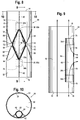
- FIG. 1 shows a tubular segment 10 of graft material.
- the tubular segment 10 includes a tubular body 12, a proximal end 16, a distal end 18, a first surface 20, a second surface 22, a length 24 that extends from the proximal end 16 to the distal end 18, and a lumen 26.
- the tubular segment 10, as shown in FIG. 1 has been flattened. In the flattened state, the tubular segment 10 also includes a width 14, a first or left lateral edge 28 and a second or right lateral edge 30. In a non-flattened state, the tubular segment 10 has a diameter.
- the graft material of the tubular segment 10 may include a flexible material, such as polytetrafluoroethylene (PTFE) or expanded PTFE (ePTFE), polyethylene terephthalate (PET), a polyester material, or other stent graft materials known in the art.
- PTFE polytetrafluoroethylene
- ePTFE expanded PTFE
- PET polyethylene terephthalate
- polyester material such as polyethylene terephthalate
- the tubular segment 10 of graft material is separated into two tubular sections 32, 34 along a partition line 40.
- Each of the first and second tubular sections 32, 34 has the same length 24 as the tubular segment 10.
- the first tubular section 32 has a width 36 in the flattened state and a diameter in the non-flattened state.
- the width 36 and diameter of the first tubular section 32 is less than the width 14 and diameter of the tubular segment 10.
- the width 36 of the first tubular section 32 extends from the left lateral edge 28 toward the right lateral edge 30 of the tubular segment 10.
- the second tubular section 34 has a width 38 in the flattened state and a diameter in the non-flattened state.
- the width 38 and diameter of the second tubular section 34 is less than the width 36 and diameter of the first tubular section 32.
- the width 38 of the second tubular section 34 extends from the right lateral edge 30 toward the left lateral edge 28, or, in other words, from the first tubular section 32 to the right lateral edge 30.
- the combined or total width of the first and second tubular sections 32, 34 is the same as the width 14 of the tubular segment 10.
- the first or left lateral edge of the first tubular section 32 is the same as the left lateral edge 28 of the tubular segment 10, and the second or right lateral edge of the first tubular section 32 is the partition line 40.
- the first or left lateral edge of the second tubular section 34 is the partition line 40, and the second or right lateral edge of the second tubular section 34 is the same as the right lateral edge 30 of the tubular segment 10.
- the second tubular section 34 is separated into five sections or sub-sections 34a, 34b, 34c, 34d, and 34e, as shown in FIG. 1 .
- Each sub-section 34a, 34b, 34c, 34d, and 34e has the same width 38 as the second tubular section 34.
- the first sub-section 34a extends from proximal end 16 toward the distal end 18 for a length
- the second sub-section 34b extends from the first sub-section 34a toward the distal end 18 for a length
- the third sub-section 34c extends from the second sub-section 34b toward the distal end 18 for a length
- the fourth sub-section 34d extends from the third sub-section 34c toward the distal end 18 for a length
- the fifth sub-section 34e extends from the fourth sub-section 34d to the distal end 18 and comprises a length. As shown in FIGS.
- the length of the third sub-section 34c may be greater than the lengths of the first, second, fourth and fifth sub-sections 34a, 34b, 34d, 34e, which are approximately equal.
- the lengths of each sub-section 34a, 34b, 34c, 34d, and 34e may be the same or may vary, e.g., depending on a desired axial length of the bidirectional branch 48 relative to the overall axial length of the endoluminal prosthesis, or other considerations.
- the tubular segment 10 is connected along the partition line 40 within the first, second, fourth and fifth sub-sections 34a, 34b, 34d, 34e of the second tubular section 34.
- the tubular segment 10 is connected via sewing or stitching the tubular segment 10 along the partition line 40, as shown in FIG. 2 .
- the tubular segment 10 remains unconnected along the partition line 40 within the third sub-section 34c to create an opening 44 for the second tubular section 34 that is described in further detail below.
- the separation of the first and second tubular sections 32, 34 creates a lumen 42 of the second tubular section 34.
- the second, third, and fourth sub-sections 34b, 34c, 34d form the internal bidirectional branch 48 and therefore the first and fifth sub-sections 34a, 34e are removed.
- the first and fifth sub-sections 34a, 34e of the second tubular section 34 are removed from the tubular segment 10 by cutting adjacent to the partition line within the first and fifth sub-sections 34a, 34e and along respective ends of the first and fifth sub-sections 34a, 34e adjacent to the second sub-section 34b and the fourth sub-section 34d, respectively. As shown in FIG.
- the sewn partition line 40 within the first and fifth sub-sections 34a, 34e is maintained such that the first tubular section 32 is not open or otherwise exposed along the partition line 40 where the first and fifth sub-sections 34a, 34e previously were connected.
- the second tubular section 34 is separated into three sections or sub-sections rather than five sections or sub-sections such that the first sub-section comprises sub-sections 34a and 34b of the previously described embodiment, the second sub-section comprises sub-section 34c of the previously described embodiment, and the third sub-section comprises sub-sections 34d and 34e of the previously described embodiment.
- the first and third sub-sections of the alternative embodiment may not be cut and removed.
- the internal bidirectional branch would comprise a length that is equal to the length 24 of the tubular segment 10. The method of making this embodiment of bidirectional branch would otherwise include the same steps described above and below regarding the endoluminal prosthesis comprising the internal bidirectional branch 48.
- wire 50 is added to the internal bidirectional branch 48, as shown in FIG. 3 .
- Wire 50 may include nitinol wire or a bow wire and is added via stitching or sewing wire 50 to the graft material of the tubular segment 10.
- Wire 50 is added to the internal bidirectional branch 48 around proximal and distal ends of the second and fourth sub-sections 34b, 34d, as shown in FIG. 3 , and along the right lateral edge 30 within the second and fourth sub-sections 34b, 34d. Wire is also added along the right lateral edge 30 within the third sub-section 34c.
- nitinol wire is added to the internal bidirectional branch 48 around proximal and distal ends of the second and fourth sub-sections 34b, 34d and along the right lateral edge 30 within the second and fourth sub-sections 34b, 34d, and a bow wire is added along the right lateral edge 30 within the third sub-section 34c.
- wire 50 may be added at additional locations or areas on the second and fourth sub-sections 34b, 34d to support the shape of the internal bidirectional branch 48.
- the tubular segment 10 After removal of the first and fifth sub-sections 34a, 34e and the addition of wire 50 to the internal bidirectional branch 48, the tubular segment 10 is turned inside out to form an endoluminal prosthesis 54, as shown in FIG. 4 , such that the internal bidirectional branch 48 is located inside or internally within a main lumen 46 of the endoluminal prosthesis 54.
- the first surface 20 of the first tubular section 32 Prior to turning the tubular segment 10 inside out, the first surface 20 of the first tubular section 32 was located on the exterior of the tubular segment 10 and the second surface 22 of the first tubular section 32 was located on the interior of the tubular segment 10, as shown in FIGS. 1-3 .
- the second surface 22 of the first tubular section 32 forms the exterior of the endoluminal prosthesis 54 and the first surface 20 of the first tubular section 32 forms the interior of the endoluminal prosthesis 54.
- FIG. 5 shows a side view of the endoluminal prosthesis 54 with the internal bidirectional branch 48 located internally within the main lumen 46 of the endoluminal prosthesis 54. After turning the tubular segment 10 inside out, the opening 44 of the internal bidirectional branch 48 is exposed. As shown in FIG. 5 , the opening 44 forms an oval-shaped slit prior to expansion, which is described in detail below.
- a plurality of stents 52 may be added to the exterior of the endoluminal prosthesis 54, which is the second surface 22 of the first tubular section 32, to support the shape of the endoluminal prosthesis 54 and to facilitate positioning of the endoluminal prosthesis 54 within the aorta.
- the plurality of stents 52 may include Z-stents, Gianturco stent design or other stent designs.
- the plurality of stents 52 connected to the endoluminal prosthesis 54 are Z-stents.
- Each Z-stent may include a series of substantially straight segments or struts interconnected by a series of bent segments or bends.
- the bent segments may include acute bends or apices.
- the Z-stents are arranged in a Zigzag configuration in which the straight segments are set at angles relative to one another and are connected by the bent segments. This design provides both significant radial force as well as longitudinal support.
- Alternative stents may include, for example, annular or helical stents.
- external stents may have the potential to become intertwined with the wires or other devices utilized to ensure branch vessel access, sealing, and fixation.
- the plurality of stents 52 include at least two rows 62, 64 of stents, as shown in FIG. 6 .
- the plurality of stents 52 are positioned around the opening 44 of the internal bidirectional branch 48 such that an apex 60 of the first row 62 of Z-stents align with a proximal end 56 of the opening 44 and an apex 60 of the second row 64 of Z-stents align with a distal end 58 of the opening 44, as shown in FIG. 6 .
- the Z-stents form a quadrilateral around the opening 44.
- the quadrilateral may include the shape of a parallelogram and/or a rhombus.
- FIG. 7 shows a side view of the endoluminal prosthesis 54 with the internal bidirectional branch 48.
- the graft material surrounding the opening 44 and within the quadrilateral formed between the first and second rows 62, 64 of Z-stents surrounding the opening 44 are puckered to facilitate cutting the graft material adjacent to the Z-stents and within the quadrilateral.
- FIG. 7 shows a side view of the endoluminal prosthesis 54 with the internal bidirectional branch 48.
- FIG. 7 shows a cutting line 66 that begins at the apex 60a of the second row 64 of Z-stents adjacent to the distal end 58 of the opening 44 and continues along a straight segment 68 of the second row 64 of Z-stents away from the opening 44 until the subsequent apex 60b of the second row 64 of Z-stents.
- the cutting line 66 then extends from the apex 60b of the second row 64 of Z-stents to the adjacent apex 60c of the first row 62 of Z-stents and continues along a straight segment 68 of the first row 62 of Z-stents toward the opening 44 until the apex 60d of the first row 62 of Z-stents adjacent to the proximal end 56 of the opening 44.
- a corresponding cutting line is located on the opposite side of the opening 44 (not shown).
- the exterior of the graft material is cut along the cutting line 66 on both sides of the opening 44 such that free edges 70 of the graft material are formed.
- the opening 44 is increased to be the size of the quadrilateral between the first row 62 and the second row 64 of Z-stents by opening and/or pushing the graft material inward toward the interior of the main lumen 46 of the endoluminal prosthesis 54, and then the free edges 70 of the graft material are attached to the graft material and/or the stents 52 where the graft material was initially cut, as shown in FIG. 8 .
- the free edges 70 may be connected to the graft material near the stents 52 via tacks to facilitate stitching or sewing of the free edges 70 back to the graft material near the stents 52 and/or to the stents 52. During stitching or sewing, the tacks may be removed.
- FIG. 8 shows a sewing line 72 where the free edges 70 are connected to the graft material near the stents 52 and/or to the stents 52.
- FIG. 8 also shows the increased size of the opening 44 that mirrors the size of the quadrilateral between the first and second rows 62, 64 of Z-stents between the apices 60 of the Z-stent located near the proximal and distal ends 56, 58 of the opening 44.
- the opening 44 may be similarly puckered, cut and attached to the graft material and/or stents 52 to mirror the shape between two rows of stents 52 and to increase the size of the opening 44 of the internal bidirectional branch 48 to facilitate ease of cannulation and the ability to access the internal bidirectional branch 48 from the exterior of the endoluminal prosthesis 54 from several angles or directions.
- FIG. 9 shows a cross-sectional side view of the internal bidirectional branch 48 positioned internally within the main lumen 46 of the endoluminal prosthesis 54
- FIG. 10 shows an end view of the internal bidirectional branch 48 with the main lumen 46 of the endoluminal prosthesis 54.
- a cannula or tube may be inserted through the opening 44 of the internal bidirectional branch 48 and then exit the internal bidirectional branch 48 either through a distal end 74 of the internal bidirectional branch 48 toward the distal end 18 of the endoluminal prosthesis 54 or through a proximal end 76 of the internal bidirectional branch 48 toward the proximal end 16 of the endoluminal prosthesis 54.
- the cannula or tube may be inserted through the internal bidirectional branch 48 either through the distal end 74 and out of the opening 44 or through the proximal end 76 of the internal bidirectional branch 48 and out of the opening 44.
- the arrows 78 in FIG. 9 show the respective two directions that a cannula or tube may exit the internal bidirectional branch 48.
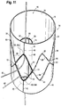
- FIG. 11 shows a perspective view of two cannulas or tubes 80 inserted through the opening 44 of the internal bidirectional branch 48 with one tube 80 extending out of the distal end 74 of the internal bidirectional branch 48 and the distal end 18 of the endoluminal prosthesis 54 and the second tube 80 extending out of the proximal end 76 of the internal bidirectional branch 48 and the proximal end 16 of the endoluminal prosthesis 54.
- the present embodiments allow for the construction of an endoluminal prosthesis with an internal bidirectional branch from a single piece of graft material.
- the simplified construction decreases the number of materials, costs, and manufacturing time to make an endoluminal prosthesis with an internal bidirectional branch.
- the simplified construction also eliminates the need for making a separate branch for connection to the endoluminal prosthesis.
- the simplified construction also decreases interference of multiple tubes or cannulas within the lumen of the endoluminal prosthesis.
- the present embodiments enable cannulation of a branch vessel from several directions.
- the enlarged opening of the internal bidirectional branch allows access to one or more the branch vessels and decreases the complexity of the trying to cannulate through a small opening.
- the enlarged opening of the internal bidirectional branch also for multiple cannulas and/or tubes to be inserted through the opening.
- the enlarged opening of the internal bidirectional branch also allows cannulation is multiple directions when it may not be clear if the vessel is best cannulated from one direction.
- the present embodiments enable cannulation through at least two directions within the internal bidirectional branch. Specifically, cannulation may occur through either the proximal or distal ends of the internal bidirectional branch.
- the multiple exits of the internal branch allows for the insertion of multiple cannulas or tubes with decreased interference within the internal bidirectional branch and the ability to access the branched vessel from different directions within the endoluminal prosthesis.
Landscapes
- Health & Medical Sciences (AREA)
- Engineering & Computer Science (AREA)
- Biomedical Technology (AREA)
- Heart & Thoracic Surgery (AREA)
- Oral & Maxillofacial Surgery (AREA)
- Transplantation (AREA)
- Cardiology (AREA)
- Vascular Medicine (AREA)
- Life Sciences & Earth Sciences (AREA)
- Animal Behavior & Ethology (AREA)
- General Health & Medical Sciences (AREA)
- Public Health (AREA)
- Veterinary Medicine (AREA)
- Pulmonology (AREA)
- Gastroenterology & Hepatology (AREA)
- Prostheses (AREA)
Abstract
Description
- The present invention relates to methods of making an internal bidirectional branch within an endoluminal prosthesis, such as for branched endovascular procedures.
- Endovascular aortic aneurysm repair is practiced by a wide range of physicians across varying specialties. An aortic aneurysm is an enlargement of the aorta of a patient caused by weakening in the wall of the aorta. If an aortic aneurysm is untreated, it may rupture and cause serious health complications.
- The surgical procedure for endovascular aortic aneurysm repair involves the placement of a stent graft within the aorta of a patient to seal off the aneurysm from blood flow to prevent the aneurysm from expanding. Physicians often use the procedure to treat abdominal aortic aneurysms (AAA), thoracic aortic aneurysms (TAA), thoraco-abdominal aortic aneurysms (TAAA), and aneurysms in other locations of the patient.
- The aorta has many branches to other vessels or arteries, such as the renal arteries, the superior mesenteric artery (SMA), the inferior mesenteric artery, and the left and right internal iliac arteries. Branch vessels are also connected to the head, arms, spinal cord, intestines and/or kidneys. Endovascular repair of aneurysms occurring at or near branch vessels requires that blood flow to the branch vessel is maintained and access to the branch vessel for cannulation is available.
- Stent grafts may include internal branches to cannulate branch vessels and to maintain blood flow to the branch vessels. However, these internal branches often only include a small opening or access in one direction within the stent graft for physicians to cannulate the branch vessel. Often times, it is unknown or not clear which direction the branch vessel is best cannulated. These factors increase the difficulty of cannulation, which can lead to complications during the surgical procedure for endovascular aortic aneurysm repair.
- This invention concerns a method of making an internal bidirectional branch within an endoluminal prosthesis that enables cannulation of a branch vessel from several directions and allows surgeons the ability to access the outside of the endoluminal prosthesis through the bidirectional branch from several directions. The method also provides a simplified construction of an endoluminal prosthesis with a bidirectional branch and eliminates the need for making a separate branch for connection to an endoluminal prosthesis.
- The present invention relates to a method of making a bidirectional branch within an endoluminal prosthesis. The method includes laying a tubular segment of graft material flat. The tubular segment of graft material includes a first lateral edge, a second lateral edge, a width extending from the first lateral edge to the second lateral edge, and a length extending from a proximal end to a distal end of the tubular segment. The method also includes partitioning the tubular segment into first and second sections along the length of the tubular segment. The first section extends from the first lateral edge toward the second lateral edge and includes a width less than the width of the tubular segment. The second section extends from the second lateral edge toward the first lateral edge and includes a width less than the width of the first section such that a total width of the first and second sections is the same as the width of the tubular segment. The method also includes partitioning the second section of the tubular segment into at least three sub-sections. A first sub-section extends from the proximal end toward the distal end for a length, a second sub-section extends from the first sub-section toward the distal end for a length, and a third sub-section extends from the second sub-section to the distal end and has a length. A total length of the three sub-sections is the same as the length of the tubular segment. The method further includes connecting the tubular segment along a lateral edge of the first sub-section from the proximal end to the second sub-section and along a lateral edge of the third sub-section from the distal end to the second sub-section. The lateral edges of the first and third sub-sections are opposite the second lateral edge of the tubular segment. The method also includes turning the tubular segment inside out such that the first, second and third sub-sections of the second sub-section form the bidirectional branch, the bidirectional branch is positioned within a lumen of the endoluminal prosthesis, and an opening of the third sub-section is exposed.
- Another aspect provides a method of making an internal bidirectional branch for an endoluminal prosthesis from a tubular segment of graft material. The method includes partitioning a tubular segment of graft material into two tubular sections. The tubular segment of graft material having a lumen, a diameter, and a length extending from a proximal end to a distal end of the tubular segment. Each tubular section having the same length as the tubular segment of graft material. The first tubular section includes a diameter less than the diameter of the tubular segment of graft material, and the second tubular section includes a diameter less than the diameter of the first tubular section such that a total diameter of the first and second tubular sections is the same as the diameter of the tubular segment of graft material. The method also includes partitioning the second tubular section into five sub-sections along the length of the tubular segment of graft material, wherein a total length of the five sub-sections is the same as the length of the tubular segment of graft material. A first sub-section extends from the proximal end toward the distal end for a length, a second sub-section extends from the first section toward the distal end for a length, a third sub-section extends from the second sub-section toward the distal end for a length, a fourth sub-section extends from the third sub-section toward the distal end for a length, and a fifth sub-section extends from the fourth section to the distal end and has a length. The method also includes connecting the tubular segment of graft material along the first, second, fourth, and fifth sub-sections of the second tubular section to separate the first tubular section and the second tubular section and removing the first and fifth sub-sections of the second tubular section from the tubular segment while maintaining connected edges of the first and fifth sub-sections such that the second, third and fourth sub-sections form the bidirectional branch. The method further includes turning the tubular segment inside out such that the bidirectional branch is positioned within a main lumen of the endoluminal prosthesis and an opening of the third sub-section is exposed.
- Another aspect provides a method of making an internal bidirectional branch for an endoluminal prosthesis including laying a tubular segment of graft material flat. The tubular segment of graft material includes a first lateral edge, a second lateral edge, a width extending from the first lateral edge to the second lateral edge, and a length extending from a proximal end to a distal end of the tubular segment. The method also includes partitioning the tubular segment into first and second sections along the length of the tubular segment. The first section extends from the first lateral edge toward the second lateral edge and has a width less than the width of the tubular segment, and the second section extends from the second lateral edge toward the first lateral edge and has a width less than the width of the first section such that a total width of the first and second sections is the same as the width of the tubular segment. The method also includes partitioning the second section of the tubular segment into at least three sub-sections, wherein each section has the width of the second section. A first sub-section extends from the proximal end toward the distal end for a length, a second sub-section extends from the first sub-section toward the distal end for a length, and a third sub-section extends from the second section to the distal end and has a length. A total length of the five sections is the same as the length of the tubular segment. The method further includes connecting the tubular segment along a lateral edge of the first sub-section from the proximal end to the second sub-section and along a lateral edge of the third sub-section from the distal end to the second sub-section. The lateral edges of the first and third sub-sections are opposite the second lateral edge of the tubular segment. The method also includes turning the tubular segment inside out such that the first, second and third sub-sections of the second section form the bidirectional branch, the bidirectional branch is positioned within a lumen of the endoluminal prosthesis, and an opening of the third section is exposed. The method also includes connecting a plurality of stents to an exterior surface of the endoluminal prosthesis.
- The present invention also relates to stent grafts formed by the disclosed methods.
- Other aspects, features and advantages of the teachings herein are set out in the specific description that follows.
- Embodiments of the present invention are described below, by way of example only, with reference to the accompanying drawings, in which:
-
FIG. 1 shows a flattened perspective view of a tubular segment of graft material; -
FIG. 2 shows a flattened perspective view of the tubular segment of graft material ofFIG. 1 separated into first and second tubular sections; -
FIG. 3 shows a flatten perspective view of the tubular segment of graft material ofFIG. 1 with two sub-sections of the second tubular section removed to form a bidirectional branch; -
FIG. 4 shows a perspective view of turning the tubular segment of graft material ofFIG. 1 inside out; -
FIG. 5 shows a side view of the tubular segment of graft material ofFIG. 1 after being turned inside out; -
FIG. 6 shows a side view of the tubular segment of graft material ofFIG. 1 after being turned inside out with a plurality of stents; -
FIG. 7 shows another side view of the tubular segment of graft material ofFIG. 1 after being turned inside out and cut to expose free edges of an opening of the bidirectional branch; -
FIG. 8 shows another side view of the tubular segment of graft material ofFIG. 1 turned inside out and after attaching the free edges of the opening of the bidirectional branch to the graft material and/or plurality of stents; -
FIG. 9 shows a cross-sectional side view of the endoluminal prosthesis with the internal bidirectional branch ofFIG. 8 taken along lines 9-9; -
FIG. 10 shows an end view of the endoluminal prosthesis with the internal bidirectional branch ofFIG. 8 taken along lines 10-10; and -
FIG. 11 shows a perspective view of cannulating the endoluminal prosthesis with the internal bidirectional branch in at least two directions. - In the present disclosure, the term "proximal" refers to a direction that is generally closest to the heart during a medical procedure, while the term "distal" refers to a direction that is farthest from the heart during a medical procedure.
- The term "prosthesis" refers to any device for insertion or implantation into or replacement for a body part or a function of that body part. The term also may refer to a device that enhances or adds functionality to a physiological system. The term prosthesis may include, for example and without limitation, a stent, stent-graft, filter, valve, balloon, embolization coil, and the like.
-
FIG. 1 shows atubular segment 10 of graft material. Thetubular segment 10 includes atubular body 12, aproximal end 16, adistal end 18, afirst surface 20, asecond surface 22, alength 24 that extends from theproximal end 16 to thedistal end 18, and alumen 26. Thetubular segment 10, as shown inFIG. 1 , has been flattened. In the flattened state, thetubular segment 10 also includes awidth 14, a first or leftlateral edge 28 and a second or rightlateral edge 30. In a non-flattened state, thetubular segment 10 has a diameter. The graft material of thetubular segment 10 may include a flexible material, such as polytetrafluoroethylene (PTFE) or expanded PTFE (ePTFE), polyethylene terephthalate (PET), a polyester material, or other stent graft materials known in the art. - To form an endoluminal prosthesis with an internal
bidirectional branch 48, thetubular segment 10 of graft material is separated into twotubular sections partition line 40. Each of the first and secondtubular sections same length 24 as thetubular segment 10. The firsttubular section 32 has awidth 36 in the flattened state and a diameter in the non-flattened state. Thewidth 36 and diameter of the firsttubular section 32 is less than thewidth 14 and diameter of thetubular segment 10. Thewidth 36 of the firsttubular section 32 extends from the leftlateral edge 28 toward the rightlateral edge 30 of thetubular segment 10. The secondtubular section 34 has awidth 38 in the flattened state and a diameter in the non-flattened state. Thewidth 38 and diameter of the secondtubular section 34 is less than thewidth 36 and diameter of the firsttubular section 32. Thewidth 38 of the secondtubular section 34 extends from the rightlateral edge 30 toward the leftlateral edge 28, or, in other words, from the firsttubular section 32 to the rightlateral edge 30. The combined or total width of the first and secondtubular sections width 14 of thetubular segment 10. - The first or left lateral edge of the first
tubular section 32 is the same as the leftlateral edge 28 of thetubular segment 10, and the second or right lateral edge of the firsttubular section 32 is thepartition line 40. The first or left lateral edge of the secondtubular section 34 is thepartition line 40, and the second or right lateral edge of the secondtubular section 34 is the same as the rightlateral edge 30 of thetubular segment 10. - To form the internal
bidirectional branch 48, the secondtubular section 34 is separated into five sections orsub-sections FIG. 1 . Eachsub-section same width 38 as the secondtubular section 34. Thefirst sub-section 34a extends fromproximal end 16 toward thedistal end 18 for a length, thesecond sub-section 34b extends from thefirst sub-section 34a toward thedistal end 18 for a length, thethird sub-section 34c extends from thesecond sub-section 34b toward thedistal end 18 for a length, thefourth sub-section 34d extends from thethird sub-section 34c toward thedistal end 18 for a length, and thefifth sub-section 34e extends from thefourth sub-section 34d to thedistal end 18 and comprises a length. As shown inFIGS. 1-3 , the length of thethird sub-section 34c may be greater than the lengths of the first, second, fourth andfifth sub-sections bidirectional branch 48 relative to the overall axial length of the endoluminal prosthesis, or other considerations. - To separate the first and second
tubular sections tubular segment 10 is connected along thepartition line 40 within the first, second, fourth andfifth sub-sections tubular section 34. Thetubular segment 10 is connected via sewing or stitching thetubular segment 10 along thepartition line 40, as shown inFIG. 2 . Thetubular segment 10 remains unconnected along thepartition line 40 within thethird sub-section 34c to create anopening 44 for the secondtubular section 34 that is described in further detail below. The separation of the first and secondtubular sections lumen 42 of the secondtubular section 34. - The second, third, and
fourth sub-sections bidirectional branch 48 and therefore the first andfifth sub-sections fifth sub-sections tubular section 34 are removed from thetubular segment 10 by cutting adjacent to the partition line within the first andfifth sub-sections fifth sub-sections second sub-section 34b and thefourth sub-section 34d, respectively. As shown inFIG. 3 , during the cutting and removal of the first andfifth sub-sections partition line 40 within the first andfifth sub-sections tubular section 32 is not open or otherwise exposed along thepartition line 40 where the first andfifth sub-sections - In another embodiment (not shown), to form the internal bidirectional branch, the second
tubular section 34 is separated into three sections or sub-sections rather than five sections or sub-sections such that the first sub-section comprises sub-sections 34a and 34b of the previously described embodiment, the second sub-section comprises sub-section 34c of the previously described embodiment, and the third sub-section comprisessub-sections length 24 of thetubular segment 10. The method of making this embodiment of bidirectional branch would otherwise include the same steps described above and below regarding the endoluminal prosthesis comprising the internalbidirectional branch 48. - To support the patency and shape of the internal
bidirectional branch 48,wire 50 is added to the internalbidirectional branch 48, as shown inFIG. 3 .Wire 50 may include nitinol wire or a bow wire and is added via stitching orsewing wire 50 to the graft material of thetubular segment 10.Wire 50 is added to the internalbidirectional branch 48 around proximal and distal ends of the second andfourth sub-sections FIG. 3 , and along the rightlateral edge 30 within the second andfourth sub-sections lateral edge 30 within thethird sub-section 34c. In one example, nitinol wire is added to the internalbidirectional branch 48 around proximal and distal ends of the second andfourth sub-sections lateral edge 30 within the second andfourth sub-sections lateral edge 30 within thethird sub-section 34c. In other examples,wire 50 may be added at additional locations or areas on the second andfourth sub-sections bidirectional branch 48. - After removal of the first and
fifth sub-sections wire 50 to the internalbidirectional branch 48, thetubular segment 10 is turned inside out to form anendoluminal prosthesis 54, as shown inFIG. 4 , such that the internalbidirectional branch 48 is located inside or internally within amain lumen 46 of theendoluminal prosthesis 54. Prior to turning thetubular segment 10 inside out, thefirst surface 20 of the firsttubular section 32 was located on the exterior of thetubular segment 10 and thesecond surface 22 of the firsttubular section 32 was located on the interior of thetubular segment 10, as shown inFIGS. 1-3 . After thetubular segment 10 is turned inside out, thesecond surface 22 of the firsttubular section 32 forms the exterior of theendoluminal prosthesis 54 and thefirst surface 20 of the firsttubular section 32 forms the interior of theendoluminal prosthesis 54. -
FIG. 5 shows a side view of theendoluminal prosthesis 54 with the internalbidirectional branch 48 located internally within themain lumen 46 of theendoluminal prosthesis 54. After turning thetubular segment 10 inside out, theopening 44 of the internalbidirectional branch 48 is exposed. As shown inFIG. 5 , the opening 44 forms an oval-shaped slit prior to expansion, which is described in detail below. - A plurality of stents 52 may be added to the exterior of the
endoluminal prosthesis 54, which is thesecond surface 22 of the firsttubular section 32, to support the shape of theendoluminal prosthesis 54 and to facilitate positioning of theendoluminal prosthesis 54 within the aorta. The plurality of stents 52 may include Z-stents, Gianturco stent design or other stent designs. In one example, as shown inFIG. 6 , the plurality of stents 52 connected to theendoluminal prosthesis 54 are Z-stents. - Each Z-stent may include a series of substantially straight segments or struts interconnected by a series of bent segments or bends. The bent segments may include acute bends or apices. The Z-stents are arranged in a Zigzag configuration in which the straight segments are set at angles relative to one another and are connected by the bent segments. This design provides both significant radial force as well as longitudinal support. In tortuous anatomy, branches, or fenestrations, it may be preferable to use alternative stents or modifications to the Z-stent design to avoid stent-to-stent contact. Alternative stents may include, for example, annular or helical stents. Furthermore, in complex anatomical situations, external stents may have the potential to become intertwined with the wires or other devices utilized to ensure branch vessel access, sealing, and fixation. Thus, in some instances, it may be desirable to affix some of the stents 52 to the interior or
first surface 20 of the firsttubular section 32 and/or to exterior and interior surfaces of the internalbidirectional branch 48. - The plurality of stents 52 include at least two
rows FIG. 6 . The plurality of stents 52 are positioned around theopening 44 of the internalbidirectional branch 48 such that an apex 60 of thefirst row 62 of Z-stents align with aproximal end 56 of theopening 44 and an apex 60 of thesecond row 64 of Z-stents align with adistal end 58 of theopening 44, as shown inFIG. 6 . In this configuration, the Z-stents form a quadrilateral around theopening 44. The quadrilateral may include the shape of a parallelogram and/or a rhombus. -
FIG. 7 shows a side view of theendoluminal prosthesis 54 with the internalbidirectional branch 48. To increase the size of theopening 44 to allow access to the internalbidirectional branch 48 from several directions, the graft material surrounding theopening 44 and within the quadrilateral formed between the first andsecond rows opening 44 are puckered to facilitate cutting the graft material adjacent to the Z-stents and within the quadrilateral. Specifically, for illustrative purposes,FIG. 7 shows acutting line 66 that begins at the apex 60a of thesecond row 64 of Z-stents adjacent to thedistal end 58 of theopening 44 and continues along astraight segment 68 of thesecond row 64 of Z-stents away from theopening 44 until thesubsequent apex 60b of thesecond row 64 of Z-stents. The cuttingline 66 then extends from the apex 60b of thesecond row 64 of Z-stents to theadjacent apex 60c of thefirst row 62 of Z-stents and continues along astraight segment 68 of thefirst row 62 of Z-stents toward theopening 44 until the apex 60d of thefirst row 62 of Z-stents adjacent to theproximal end 56 of theopening 44. A corresponding cutting line is located on the opposite side of the opening 44 (not shown). - The exterior of the graft material is cut along the cutting
line 66 on both sides of theopening 44 such thatfree edges 70 of the graft material are formed. Theopening 44 is increased to be the size of the quadrilateral between thefirst row 62 and thesecond row 64 of Z-stents by opening and/or pushing the graft material inward toward the interior of themain lumen 46 of theendoluminal prosthesis 54, and then thefree edges 70 of the graft material are attached to the graft material and/or the stents 52 where the graft material was initially cut, as shown inFIG. 8 . The free edges 70 may be connected to the graft material near the stents 52 via tacks to facilitate stitching or sewing of thefree edges 70 back to the graft material near the stents 52 and/or to the stents 52. During stitching or sewing, the tacks may be removed.FIG. 8 shows asewing line 72 where thefree edges 70 are connected to the graft material near the stents 52 and/or to the stents 52.FIG. 8 also shows the increased size of theopening 44 that mirrors the size of the quadrilateral between the first andsecond rows apices 60 of the Z-stent located near the proximal and distal ends 56, 58 of theopening 44. In other examples, when different stent shapes are used, theopening 44 may be similarly puckered, cut and attached to the graft material and/or stents 52 to mirror the shape between two rows of stents 52 and to increase the size of theopening 44 of the internalbidirectional branch 48 to facilitate ease of cannulation and the ability to access the internalbidirectional branch 48 from the exterior of theendoluminal prosthesis 54 from several angles or directions. -
FIG. 9 shows a cross-sectional side view of the internalbidirectional branch 48 positioned internally within themain lumen 46 of theendoluminal prosthesis 54, andFIG. 10 shows an end view of the internalbidirectional branch 48 with themain lumen 46 of theendoluminal prosthesis 54. With the construction and positioning of the internalbidirectional branch 48, during cannulation, a cannula or tube may be inserted through theopening 44 of the internalbidirectional branch 48 and then exit the internalbidirectional branch 48 either through adistal end 74 of the internalbidirectional branch 48 toward thedistal end 18 of theendoluminal prosthesis 54 or through aproximal end 76 of the internalbidirectional branch 48 toward theproximal end 16 of theendoluminal prosthesis 54. Alternatively, the cannula or tube may be inserted through the internalbidirectional branch 48 either through thedistal end 74 and out of theopening 44 or through theproximal end 76 of the internalbidirectional branch 48 and out of theopening 44. Thearrows 78 inFIG. 9 show the respective two directions that a cannula or tube may exit the internalbidirectional branch 48. -
FIG. 11 shows a perspective view of two cannulas ortubes 80 inserted through theopening 44 of the internalbidirectional branch 48 with onetube 80 extending out of thedistal end 74 of the internalbidirectional branch 48 and thedistal end 18 of theendoluminal prosthesis 54 and thesecond tube 80 extending out of theproximal end 76 of the internalbidirectional branch 48 and theproximal end 16 of theendoluminal prosthesis 54. - Advantageously, the present embodiments allow for the construction of an endoluminal prosthesis with an internal bidirectional branch from a single piece of graft material. The simplified construction decreases the number of materials, costs, and manufacturing time to make an endoluminal prosthesis with an internal bidirectional branch. The simplified construction also eliminates the need for making a separate branch for connection to the endoluminal prosthesis. The simplified construction also decreases interference of multiple tubes or cannulas within the lumen of the endoluminal prosthesis.
- As another advantage, the present embodiments enable cannulation of a branch vessel from several directions. Specifically, the enlarged opening of the internal bidirectional branch allows access to one or more the branch vessels and decreases the complexity of the trying to cannulate through a small opening. Also, for patients with closely spaced branch vessels, the enlarged opening of the internal bidirectional branch also for multiple cannulas and/or tubes to be inserted through the opening. The enlarged opening of the internal bidirectional branch also allows cannulation is multiple directions when it may not be clear if the vessel is best cannulated from one direction.
- As another advantage, the present embodiments enable cannulation through at least two directions within the internal bidirectional branch. Specifically, cannulation may occur through either the proximal or distal ends of the internal bidirectional branch. The multiple exits of the internal branch allows for the insertion of multiple cannulas or tubes with decreased interference within the internal bidirectional branch and the ability to access the branched vessel from different directions within the endoluminal prosthesis.
- It will be appreciated by those skilled in the art that changes could be made to the embodiments described above without departing from the broad inventive concept therefore. It is understood, therefore, that this invention is not limited to the particular embodiments disclosed, but it is intended to cover modifications within the spirit and scope of the present invention as defined by the claims.
- The disclosures in United States patent application number
US-15/652,561
Claims (17)
- A method of making a bidirectional branch within an endoluminal prosthesis, the method comprising:laying a tubular segment of graft material flat, the tubular segment of graft material comprising a first lateral edge, a second lateral edge, a width extending from the first lateral edge to the second lateral edge, and a length extending from a proximal end to a distal end of the tubular segment;partitioning the tubular segment into first and second sections along the length of the tubular segment, wherein the first section extends from the first lateral edge toward the second lateral edge and comprises a width less than the width of the tubular segment, and wherein the second section extends from the second lateral edge toward the first lateral edge and comprises a width less than the width of the first section such that a total width of the first and second sections is the same as the width of the tubular segment;partitioning the second section of the tubular segment into at least three sub-sections, a first sub-section extending from the proximal end toward the distal end for a length, a second sub-section extending from the first sub-section toward the distal end for a length, and a third sub-section extending from the second sub-section to the distal end and has a length; wherein a total length of the three sub-sections is the same as the length of the tubular segment;connecting the tubular segment along a lateral edge of the first sub-section from the proximal end to the second sub-section and along a lateral edge of the third sub-section from the distal end to the second sub-section, wherein the lateral edges of the first and third sub-sections are opposite the second lateral edge of the tubular segment; andturning the tubular segment inside out such that the first, second and third sub-sections of the second section form the bidirectional branch, the bidirectional branch is positioned within a lumen of the endoluminal prosthesis and an opening of the second sub-section is exposed.
- The method of claim 1, comprising:connecting wire to the graft material around first and second ends of the first sub-section and first and second ends of the third sub-section to support the patency of the first and third sub-sections; and/orconnecting wire along the second lateral edges of the first, second and third sub-sections.
- The method of any preceding claim, wherein connecting the tubular segment along the lateral edges of the first and third sub-sections comprises sewing or stitching.
- The method of preceding claim, comprising connecting a plurality of stents to an exterior surface of the endoluminal prosthesis after turning the tubular segment inside out.
- The method of claim 4, wherein at least two of the plurality of stents comprise a Z-stent, and the method further comprising positioning the at least two Z-stents around the opening of the second sub-section to form a quadrilateral.
- The method of claim 5, comprising cutting the tubular segment along the quadrilateral of the at least two Z-stents to expose free edges of the opening.
- The method of claim 6, comprising connecting the free edges of the opening to the graft material of the tubular segment proximate to the at least two Z-stents.
- A method of making an internal bidirectional branch for an endoluminal prosthesis from a tubular segment of graft material, the method comprising:partitioning a tubular segment of graft material into two tubular sections, the tubular segment having a lumen, a diameter, and a length extending from a proximal end to a distal end of the tubular segment, and each tubular section having the same length as the tubular segment of graft material;wherein the first tubular section comprises a diameter less than the diameter of the tubular segment of graft material and the second tubular section comprises a diameter less than the diameter of the first tubular section such that a total diameter of the first and second tubular sections is the same as the diameter of the tubular segment of graft material;partitioning the second tubular section into five sub-sections along the length of the tubular segment of graft material; wherein a total length of the five sub-sections is the same as the length of the tubular segment of graft material;wherein a first sub-section extends from the proximal end toward the distal end for a length, a second sub-section extends from the first section toward the distal end for a length, a third sub-section extends from the second sub-section toward the distal end for a length, a fourth sub-section extends from the third sub-section toward the distal end for a length, and a fifth sub-section extends from the fourth section to the distal end and comprises a length;connecting the tubular segment of graft material along the first, second, fourth, and fifth sub-sections of the second tubular section to separate the first tubular section and the second tubular section;removing the first and fifth sub-sections of the second tubular section from the tubular segment while maintaining connected edges of the first and fifth sub-sections such that the second, third and fourth sub-sections form the bidirectional branch; andturning the tubular segment inside out such that the bidirectional branch is positioned within a main lumen of the endoluminal prosthesis and an opening of the third sub-section is exposed.
- The method of claim 8, comprising connecting wire to the graft material around first and second ends of the second sub-section and first and second ends of the fourth sub-section to support the patency of the second and fourth sub-sections.
- The method of claim 8 or 9, wherein connecting the tubular segment of graft material along the first, second, fourth and fifth sub-sections of the second tubular section comprises sewing or stitching.
- The method of claim 10 further comprising connecting a plurality of stents to an exterior surface of the endoluminal prosthesis after turning the tubular segment inside out.
- The method of claim 11, wherein at least two of the plurality of stents comprise a Z-stent, and the method further comprising positioning the at least two Z-stents around the opening of the third sub-section to form a quadrilateral.
- The method of claim 12, comprising puckering the opening of the third sub-section, and cutting the tubular segment along the quadrilateral of the at least two Z-stents to expose free edges of the opening.
- The method of claim 13, comprising connecting the free edges of the opening to the graft material of the tubular segment proximate to the at least two Z-stents.
- The method of any one of claims 8 to 14, wherein each sub-section of the second tubular section has a diameter that is the same as the diameter of the second tubular section.
- A method of making an internal bidirectional branch for an endoluminal prosthesis, the method comprising:laying a tubular segment of graft material flat, the tubular segment of graft material comprising a first lateral edge, a second lateral edge, a width extending from the first lateral edge to the second lateral edge, and a length extending from a proximal end to a distal end of the tubular segment;partitioning the tubular segment into first and second sections along the length of the tubular segment, wherein the first section extends from the first lateral edge toward the second lateral edge and comprises a width less than the width of the tubular segment, and wherein the second section extends from the second lateral edge toward the first lateral edge and comprises a width less than the width of the first section such that a total width of the first and second sections is the same as the width of the tubular segment;partitioning the second section of the tubular segment into at least three sub-sections, each sub-section having the width of the second section, a first sub-section extending from the proximal end toward the distal end for a length, a second sub-section extending from the first section toward the distal end for a length, and a third sub-section extending from the second sub-section to the distal end and has a length; wherein a total length of the three sections is the same as the length of the tubular segment;connecting the tubular segment along a lateral edge of the first sub-section from the proximal end to the second sub-section and along a lateral edge of the third sub-section from the distal end to the second sub-section, wherein the lateral edges of the first and third sub-sections are opposite the second lateral edge of the tubular segment;turning the tubular segment inside out such that the first, second and third sub-sections of the second section form the bidirectional branch, the bidirectional branch is positioned within a lumen of the endoluminal prosthesis, and an opening of the second sub-section is exposed; andconnecting a plurality of stents to an exterior surface of the endoluminal prosthesis.
- The method of claim 16, wherein at least two of the plurality of stents comprise a Z-stent, and the method further comprising positioning the at least two Z-stents around the opening of the second sub-section to form a quadrilateral; the method optionally cutting the graft material of the tubular segment along the quadrilateral of the at least two Z-stents to expose free edges of the opening and optionally connecting the free edges of the opening to the graft material of the tubular segment proximate to the at least two Z-stents.
Applications Claiming Priority (1)
| Application Number | Priority Date | Filing Date | Title |
|---|---|---|---|
| US15/652,561 US10660770B2 (en) | 2017-07-18 | 2017-07-18 | Method of making an internal bidirectional branch |
Publications (2)
| Publication Number | Publication Date |
|---|---|
| EP3470017A1 true EP3470017A1 (en) | 2019-04-17 |
| EP3470017B1 EP3470017B1 (en) | 2023-01-18 |
Family
ID=62981147
Family Applications (1)
| Application Number | Title | Priority Date | Filing Date |
|---|---|---|---|
| EP18275097.6A Active EP3470017B1 (en) | 2017-07-18 | 2018-07-16 | Method of making an internal bidirectional branch |
Country Status (2)
| Country | Link |
|---|---|
| US (3) | US10660770B2 (en) |
| EP (1) | EP3470017B1 (en) |
Cited By (1)
| Publication number | Priority date | Publication date | Assignee | Title |
|---|---|---|---|---|
| EP3278767B1 (en) * | 2016-08-04 | 2024-02-28 | Cook Medical Technologies LLC | An endograft for treating branched vessels |
Families Citing this family (4)
| Publication number | Priority date | Publication date | Assignee | Title |
|---|---|---|---|---|
| CN109984861B (en) * | 2017-12-29 | 2025-03-07 | 杭州唯强医疗科技有限公司 | Covered stents for interventional treatment of abdominal aortic disease |
| US20240000588A1 (en) * | 2020-12-02 | 2024-01-04 | Lifetech Scientific (Shenzhen) Co. Ltd. | Covered Stent |
| CN116492108B (en) * | 2023-03-01 | 2025-05-02 | 中国医学科学院阜外医院 | Branched artery reconstruction auxiliary device and S-C branched priority aortic reconstruction system |
| CN117122445B (en) * | 2023-09-01 | 2025-09-23 | 中国人民解放军海军军医大学第一附属医院 | An abdominal aorta endovascular treatment branch stent system |
Citations (4)
| Publication number | Priority date | Publication date | Assignee | Title |
|---|---|---|---|---|
| WO2006034276A1 (en) * | 2004-09-21 | 2006-03-30 | William A. Cook Austrialia Pty. Ltd. | Side branch stent graft |
| US20080109066A1 (en) * | 2000-12-11 | 2008-05-08 | Quinn Stephen F | Bifurcated side-access intravascular stent graft |
| EP2749249A2 (en) * | 2012-12-31 | 2014-07-02 | Cook Medical Technologies LLC | Endoluminal prosthesis |
| AU2016210717B1 (en) * | 2016-08-04 | 2017-05-18 | Cook Medical Technologies Llc | An endograft for treating branched vessels |
Family Cites Families (45)
| Publication number | Priority date | Publication date | Assignee | Title |
|---|---|---|---|---|
| US6051020A (en) * | 1994-02-09 | 2000-04-18 | Boston Scientific Technology, Inc. | Bifurcated endoluminal prosthesis |
| US6576009B2 (en) * | 1995-12-01 | 2003-06-10 | Medtronic Ave, Inc. | Bifurcated intraluminal prostheses construction and methods |
| FR2748199B1 (en) * | 1996-05-02 | 1998-10-09 | Braun Celsa Sa | TRANSCUTANEOUS SURGICAL ANASTOMOSABLE VASCULAR PROSTHESIS |
| US6030414A (en) | 1997-11-13 | 2000-02-29 | Taheri; Syde A. | Variable stent and method for treatment of arterial disease |
| US6248122B1 (en) * | 1999-02-26 | 2001-06-19 | Vascular Architects, Inc. | Catheter with controlled release endoluminal prosthesis |
| US7722663B1 (en) * | 2000-04-24 | 2010-05-25 | Scimed Life Systems, Inc. | Anatomically correct endoluminal prostheses |
| US20130274857A1 (en) * | 2000-12-11 | 2013-10-17 | W. L. Gore & Associates, Inc. | Bifurcated side-access intravascular stent graft |
| US6645242B1 (en) | 2000-12-11 | 2003-11-11 | Stephen F. Quinn | Bifurcated side-access intravascular stent graft |
| DE60319353T2 (en) | 2002-03-25 | 2009-03-19 | William Cook Europe Aps | BRANCHED TANK |
| US20040230289A1 (en) * | 2003-05-15 | 2004-11-18 | Scimed Life Systems, Inc. | Sealable attachment of endovascular stent to graft |
| US20050059923A1 (en) | 2003-09-17 | 2005-03-17 | Ricardo Gamboa | Fenestration with intrinsic means of selective closure incorporated to a tubular body and used in interventional cardiovascular procedures |
| DE602005005495T2 (en) | 2004-09-02 | 2009-04-16 | Med Institute, Inc., West Lafayette | MODULAR PROSTHESIS AND METHOD FOR BRANCHED VESSELS |
| US8043366B2 (en) | 2005-09-08 | 2011-10-25 | Boston Scientific Scimed, Inc. | Overlapping stent |
| CA2659848C (en) | 2006-08-18 | 2015-10-06 | William A. Cook Australia Pty. Ltd. | Stent graft |
| US20080071343A1 (en) * | 2006-09-15 | 2008-03-20 | Kevin John Mayberry | Multi-segmented graft deployment system |
| US20100324664A1 (en) | 2006-10-18 | 2010-12-23 | Asher Holzer | Bifurcated Stent Assemblies |
| US20080139915A1 (en) * | 2006-12-07 | 2008-06-12 | Medtronic Vascular, Inc. | Vascular Position Locating and/or Mapping Apparatus and Methods |
| JP5264907B2 (en) | 2007-08-08 | 2013-08-14 | ザ クリーブランド クリニック ファウンデイション | Endovascular prosthetic device and endovascular prosthetic system using the same |
| US8236040B2 (en) * | 2008-04-11 | 2012-08-07 | Endologix, Inc. | Bifurcated graft deployment systems and methods |
| US20090259290A1 (en) * | 2008-04-14 | 2009-10-15 | Medtronic Vascular, Inc. | Fenestration Segment Stent-Graft and Fenestration Method |
| US8187313B2 (en) | 2008-08-01 | 2012-05-29 | Boston Scientific Scimed, Inc. | Bifurcation catheter assembly side catheter branch construction and methods |
| JP5574123B2 (en) | 2008-08-26 | 2014-08-20 | クック メディカル テクノロジーズ エルエルシー | Thoracic aortic stent graft with access region |
| US8915955B2 (en) | 2008-08-27 | 2014-12-23 | The Cleveland Clinic Foundation | Stent graft fixation coupling |
| US20100137973A1 (en) | 2008-12-02 | 2010-06-03 | Boston Scientific Scimed, Inc. | Layered Bifurcation Stent |
| WO2010127040A1 (en) * | 2009-04-28 | 2010-11-04 | Endologix, Inc. | Apparatus and method of placement of a graft or graft system |
| EP3034036B1 (en) * | 2009-10-13 | 2019-09-11 | Cook Medical Technologies LLC | Paraplegia prevention stent graft |
| US20110093002A1 (en) | 2009-10-20 | 2011-04-21 | Wilson-Cook Medical Inc. | Stent-within-stent arrangements |
| EP2509535B1 (en) | 2009-12-08 | 2016-12-07 | Endospan Ltd | Endovascular stent-graft system with fenestrated and crossing stent-grafts |
| WO2011100290A1 (en) | 2010-02-09 | 2011-08-18 | Cook Medical Technologies Llc | Thoracic aorta stent graft |
| US8337546B2 (en) | 2010-04-29 | 2012-12-25 | Medtronic Vascular, Inc. | Mobile external coupling for branch vessel connection |
| AU2010202544B1 (en) | 2010-06-18 | 2010-08-26 | Cook Incorporated | Side branch stent graft |
| US8870939B2 (en) * | 2010-08-21 | 2014-10-28 | Cook Medical Technologies Llc | Prosthesis having pivoting fenestration |
| US8753386B2 (en) | 2010-11-15 | 2014-06-17 | W. L. Gore & Associates, Inc. | Stent-graft having facing side branch portals |
| US8945205B2 (en) * | 2011-04-28 | 2015-02-03 | The Cleveland Clinic Foundation | Branch vessel prostheses |
| US9381078B2 (en) * | 2011-04-29 | 2016-07-05 | The Cleveland Clinic Foundation | Power and/or signal trigger wire for an endovascular delivery system |
| US9314328B2 (en) | 2011-08-16 | 2016-04-19 | W. L. Gore & Associates, Inc. | Branched stent graft device and deployment |
| US9662196B2 (en) * | 2011-09-27 | 2017-05-30 | Cook Medical Technologies Llc | Endoluminal prosthesis with steerable branch |
| GB2499377B (en) | 2012-02-01 | 2014-04-30 | Cook Medical Technologies Llc | Implantable medical device |
| US9655754B2 (en) * | 2013-01-10 | 2017-05-23 | Trivascular, Inc. | Systems and methods for guidewire crossover for bifurcated prostheses |
| US9993330B2 (en) | 2013-03-13 | 2018-06-12 | Cook Medical Technologies Llc | Endoluminal prosthesis system |
| US20140277347A1 (en) * | 2013-03-15 | 2014-09-18 | W. L. Gore & Associates, Inc. | Endoprosthetic device comprising a support channel capapble of receiving a branch endoprosthetic device |
| WO2015061669A1 (en) * | 2013-10-24 | 2015-04-30 | The Cleveland Clinic Foundation | Branched vessel prosthesis for repair of a failed stent graft |
| US9931231B2 (en) * | 2014-12-29 | 2018-04-03 | Cook Medical Technologies Llc | Support structures for prostheses with branching portions |
| EP3439583B1 (en) * | 2016-04-05 | 2020-09-09 | Bolton Medical, Inc. | Stent graft with internal tunnels and fenestrations |
| US20170340462A1 (en) | 2016-05-25 | 2017-11-30 | Bolton Medical, Inc. | Stent grafts and methods of use for treating aneurysms |
-
2017
- 2017-07-18 US US15/652,561 patent/US10660770B2/en active Active
-
2018
- 2018-07-16 EP EP18275097.6A patent/EP3470017B1/en active Active
-
2020
- 2020-05-22 US US16/881,269 patent/US11534318B2/en active Active
-
2022
- 2022-12-21 US US18/069,711 patent/US20230201012A1/en not_active Abandoned
Patent Citations (4)
| Publication number | Priority date | Publication date | Assignee | Title |
|---|---|---|---|---|
| US20080109066A1 (en) * | 2000-12-11 | 2008-05-08 | Quinn Stephen F | Bifurcated side-access intravascular stent graft |
| WO2006034276A1 (en) * | 2004-09-21 | 2006-03-30 | William A. Cook Austrialia Pty. Ltd. | Side branch stent graft |
| EP2749249A2 (en) * | 2012-12-31 | 2014-07-02 | Cook Medical Technologies LLC | Endoluminal prosthesis |
| AU2016210717B1 (en) * | 2016-08-04 | 2017-05-18 | Cook Medical Technologies Llc | An endograft for treating branched vessels |
Cited By (1)
| Publication number | Priority date | Publication date | Assignee | Title |
|---|---|---|---|---|
| EP3278767B1 (en) * | 2016-08-04 | 2024-02-28 | Cook Medical Technologies LLC | An endograft for treating branched vessels |
Also Published As
| Publication number | Publication date |
|---|---|
| US20200281749A1 (en) | 2020-09-10 |
| US10660770B2 (en) | 2020-05-26 |
| EP3470017B1 (en) | 2023-01-18 |
| US20190021887A1 (en) | 2019-01-24 |
| US20230201012A1 (en) | 2023-06-29 |
| US11534318B2 (en) | 2022-12-27 |
Similar Documents
| Publication | Publication Date | Title |
|---|---|---|
| US12133793B2 (en) | Endoluminal prosthesis having multiple branches or fenestrations and methods of deployment | |
| US20230201012A1 (en) | Stent graft having an internal bidirectional branch | |
| EP2429452B1 (en) | Endoluminal prosthesis system | |
| JP6353593B2 (en) | Endoluminal prosthesis with a bifurcated section that can be turned | |
| EP1332728B1 (en) | Supra-renal prosthesis and renal artery bypass | |
| EP2777607B1 (en) | Prosthesis having an everting pivoting fenestration | |
| EP1356788A2 (en) | Modular aneurysm repair system | |
| US20070168013A1 (en) | Vascular graft and deployment system | |
| CN107374791A (en) | Prearranged wearable type silk for intracavitary unit | |
| EP3187148A1 (en) | Endograft | |
| US10716660B2 (en) | Endograft for treating branched vessels | |
| EP3278767B1 (en) | An endograft for treating branched vessels |
Legal Events
| Date | Code | Title | Description |
|---|---|---|---|
| PUAI | Public reference made under article 153(3) epc to a published international application that has entered the european phase |
Free format text: ORIGINAL CODE: 0009012 |
|
| STAA | Information on the status of an ep patent application or granted ep patent |
Free format text: STATUS: THE APPLICATION HAS BEEN PUBLISHED |
|
| AK | Designated contracting states |
Kind code of ref document: A1 Designated state(s): AL AT BE BG CH CY CZ DE DK EE ES FI FR GB GR HR HU IE IS IT LI LT LU LV MC MK MT NL NO PL PT RO RS SE SI SK SM TR |
|
| AX | Request for extension of the european patent |
Extension state: BA ME |
|
| STAA | Information on the status of an ep patent application or granted ep patent |
Free format text: STATUS: REQUEST FOR EXAMINATION WAS MADE |
|
| 17P | Request for examination filed |
Effective date: 20191017 |
|
| RBV | Designated contracting states (corrected) |
Designated state(s): AL AT BE BG CH CY CZ DE DK EE ES FI FR GB GR HR HU IE IS IT LI LT LU LV MC MK MT NL NO PL PT RO RS SE SI SK SM TR |
|
| GRAP | Despatch of communication of intention to grant a patent |
Free format text: ORIGINAL CODE: EPIDOSNIGR1 |
|
| STAA | Information on the status of an ep patent application or granted ep patent |
Free format text: STATUS: GRANT OF PATENT IS INTENDED |
|
| INTG | Intention to grant announced |
Effective date: 20220407 |
|
| GRAJ | Information related to disapproval of communication of intention to grant by the applicant or resumption of examination proceedings by the epo deleted |
Free format text: ORIGINAL CODE: EPIDOSDIGR1 |
|
| STAA | Information on the status of an ep patent application or granted ep patent |
Free format text: STATUS: REQUEST FOR EXAMINATION WAS MADE |
|
| GRAP | Despatch of communication of intention to grant a patent |
Free format text: ORIGINAL CODE: EPIDOSNIGR1 |
|
| STAA | Information on the status of an ep patent application or granted ep patent |
Free format text: STATUS: GRANT OF PATENT IS INTENDED |
|
| INTC | Intention to grant announced (deleted) | ||
| INTG | Intention to grant announced |
Effective date: 20220809 |
|
| GRAS | Grant fee paid |
Free format text: ORIGINAL CODE: EPIDOSNIGR3 |
|
| GRAA | (expected) grant |
Free format text: ORIGINAL CODE: 0009210 |
|
| STAA | Information on the status of an ep patent application or granted ep patent |
Free format text: STATUS: THE PATENT HAS BEEN GRANTED |
|
| AK | Designated contracting states |
Kind code of ref document: B1 Designated state(s): AL AT BE BG CH CY CZ DE DK EE ES FI FR GB GR HR HU IE IS IT LI LT LU LV MC MK MT NL NO PL PT RO RS SE SI SK SM TR |
|
| REG | Reference to a national code |
Ref country code: GB Ref legal event code: FG4D |
|
| REG | Reference to a national code |
Ref country code: DE Ref legal event code: R096 Ref document number: 602018045480 Country of ref document: DE |
|
| REG | Reference to a national code |
Ref country code: CH Ref legal event code: EP |
|
| REG | Reference to a national code |
Ref country code: AT Ref legal event code: REF Ref document number: 1544276 Country of ref document: AT Kind code of ref document: T Effective date: 20230215 Ref country code: IE Ref legal event code: FG4D |
|
| REG | Reference to a national code |
Ref country code: LT Ref legal event code: MG9D |
|
| REG | Reference to a national code |
Ref country code: NL Ref legal event code: MP Effective date: 20230118 |
|
| REG | Reference to a national code |
Ref country code: AT Ref legal event code: MK05 Ref document number: 1544276 Country of ref document: AT Kind code of ref document: T Effective date: 20230118 |
|
| PG25 | Lapsed in a contracting state [announced via postgrant information from national office to epo] |
Ref country code: NL Free format text: LAPSE BECAUSE OF FAILURE TO SUBMIT A TRANSLATION OF THE DESCRIPTION OR TO PAY THE FEE WITHIN THE PRESCRIBED TIME-LIMIT Effective date: 20230118 |
|
| P01 | Opt-out of the competence of the unified patent court (upc) registered |
Effective date: 20230602 |
|
| PG25 | Lapsed in a contracting state [announced via postgrant information from national office to epo] |
Ref country code: RS Free format text: LAPSE BECAUSE OF FAILURE TO SUBMIT A TRANSLATION OF THE DESCRIPTION OR TO PAY THE FEE WITHIN THE PRESCRIBED TIME-LIMIT Effective date: 20230118 Ref country code: PT Free format text: LAPSE BECAUSE OF FAILURE TO SUBMIT A TRANSLATION OF THE DESCRIPTION OR TO PAY THE FEE WITHIN THE PRESCRIBED TIME-LIMIT Effective date: 20230518 Ref country code: NO Free format text: LAPSE BECAUSE OF FAILURE TO SUBMIT A TRANSLATION OF THE DESCRIPTION OR TO PAY THE FEE WITHIN THE PRESCRIBED TIME-LIMIT Effective date: 20230418 Ref country code: LV Free format text: LAPSE BECAUSE OF FAILURE TO SUBMIT A TRANSLATION OF THE DESCRIPTION OR TO PAY THE FEE WITHIN THE PRESCRIBED TIME-LIMIT Effective date: 20230118 Ref country code: LT Free format text: LAPSE BECAUSE OF FAILURE TO SUBMIT A TRANSLATION OF THE DESCRIPTION OR TO PAY THE FEE WITHIN THE PRESCRIBED TIME-LIMIT Effective date: 20230118 Ref country code: HR Free format text: LAPSE BECAUSE OF FAILURE TO SUBMIT A TRANSLATION OF THE DESCRIPTION OR TO PAY THE FEE WITHIN THE PRESCRIBED TIME-LIMIT Effective date: 20230118 Ref country code: ES Free format text: LAPSE BECAUSE OF FAILURE TO SUBMIT A TRANSLATION OF THE DESCRIPTION OR TO PAY THE FEE WITHIN THE PRESCRIBED TIME-LIMIT Effective date: 20230118 Ref country code: AT Free format text: LAPSE BECAUSE OF FAILURE TO SUBMIT A TRANSLATION OF THE DESCRIPTION OR TO PAY THE FEE WITHIN THE PRESCRIBED TIME-LIMIT Effective date: 20230118 |
|
| PG25 | Lapsed in a contracting state [announced via postgrant information from national office to epo] |
Ref country code: SE Free format text: LAPSE BECAUSE OF FAILURE TO SUBMIT A TRANSLATION OF THE DESCRIPTION OR TO PAY THE FEE WITHIN THE PRESCRIBED TIME-LIMIT Effective date: 20230118 Ref country code: PL Free format text: LAPSE BECAUSE OF FAILURE TO SUBMIT A TRANSLATION OF THE DESCRIPTION OR TO PAY THE FEE WITHIN THE PRESCRIBED TIME-LIMIT Effective date: 20230118 Ref country code: IS Free format text: LAPSE BECAUSE OF FAILURE TO SUBMIT A TRANSLATION OF THE DESCRIPTION OR TO PAY THE FEE WITHIN THE PRESCRIBED TIME-LIMIT Effective date: 20230518 Ref country code: GR Free format text: LAPSE BECAUSE OF FAILURE TO SUBMIT A TRANSLATION OF THE DESCRIPTION OR TO PAY THE FEE WITHIN THE PRESCRIBED TIME-LIMIT Effective date: 20230419 Ref country code: FI Free format text: LAPSE BECAUSE OF FAILURE TO SUBMIT A TRANSLATION OF THE DESCRIPTION OR TO PAY THE FEE WITHIN THE PRESCRIBED TIME-LIMIT Effective date: 20230118 |
|
| REG | Reference to a national code |
Ref country code: DE Ref legal event code: R097 Ref document number: 602018045480 Country of ref document: DE |
|
| PG25 | Lapsed in a contracting state [announced via postgrant information from national office to epo] |
Ref country code: SM Free format text: LAPSE BECAUSE OF FAILURE TO SUBMIT A TRANSLATION OF THE DESCRIPTION OR TO PAY THE FEE WITHIN THE PRESCRIBED TIME-LIMIT Effective date: 20230118 Ref country code: RO Free format text: LAPSE BECAUSE OF FAILURE TO SUBMIT A TRANSLATION OF THE DESCRIPTION OR TO PAY THE FEE WITHIN THE PRESCRIBED TIME-LIMIT Effective date: 20230118 Ref country code: EE Free format text: LAPSE BECAUSE OF FAILURE TO SUBMIT A TRANSLATION OF THE DESCRIPTION OR TO PAY THE FEE WITHIN THE PRESCRIBED TIME-LIMIT Effective date: 20230118 Ref country code: DK Free format text: LAPSE BECAUSE OF FAILURE TO SUBMIT A TRANSLATION OF THE DESCRIPTION OR TO PAY THE FEE WITHIN THE PRESCRIBED TIME-LIMIT Effective date: 20230118 Ref country code: CZ Free format text: LAPSE BECAUSE OF FAILURE TO SUBMIT A TRANSLATION OF THE DESCRIPTION OR TO PAY THE FEE WITHIN THE PRESCRIBED TIME-LIMIT Effective date: 20230118 |
|
| PLBE | No opposition filed within time limit |
Free format text: ORIGINAL CODE: 0009261 |
|
| STAA | Information on the status of an ep patent application or granted ep patent |
Free format text: STATUS: NO OPPOSITION FILED WITHIN TIME LIMIT |
|
| PG25 | Lapsed in a contracting state [announced via postgrant information from national office to epo] |
Ref country code: SK Free format text: LAPSE BECAUSE OF FAILURE TO SUBMIT A TRANSLATION OF THE DESCRIPTION OR TO PAY THE FEE WITHIN THE PRESCRIBED TIME-LIMIT Effective date: 20230118 |
|
| 26N | No opposition filed |
Effective date: 20231019 |
|
| PG25 | Lapsed in a contracting state [announced via postgrant information from national office to epo] |
Ref country code: SI Free format text: LAPSE BECAUSE OF FAILURE TO SUBMIT A TRANSLATION OF THE DESCRIPTION OR TO PAY THE FEE WITHIN THE PRESCRIBED TIME-LIMIT Effective date: 20230118 |
|
| PG25 | Lapsed in a contracting state [announced via postgrant information from national office to epo] |
Ref country code: MC Free format text: LAPSE BECAUSE OF FAILURE TO SUBMIT A TRANSLATION OF THE DESCRIPTION OR TO PAY THE FEE WITHIN THE PRESCRIBED TIME-LIMIT Effective date: 20230118 |
|
| PG25 | Lapsed in a contracting state [announced via postgrant information from national office to epo] |
Ref country code: MC Free format text: LAPSE BECAUSE OF FAILURE TO SUBMIT A TRANSLATION OF THE DESCRIPTION OR TO PAY THE FEE WITHIN THE PRESCRIBED TIME-LIMIT Effective date: 20230118 |
|
| REG | Reference to a national code |
Ref country code: CH Ref legal event code: PL |
|
| REG | Reference to a national code |
Ref country code: BE Ref legal event code: MM Effective date: 20230731 |
|
| PG25 | Lapsed in a contracting state [announced via postgrant information from national office to epo] |
Ref country code: LU Free format text: LAPSE BECAUSE OF NON-PAYMENT OF DUE FEES Effective date: 20230716 |
|
| PG25 | Lapsed in a contracting state [announced via postgrant information from national office to epo] |
Ref country code: LU Free format text: LAPSE BECAUSE OF NON-PAYMENT OF DUE FEES Effective date: 20230716 |
|
| PG25 | Lapsed in a contracting state [announced via postgrant information from national office to epo] |
Ref country code: CH Free format text: LAPSE BECAUSE OF NON-PAYMENT OF DUE FEES Effective date: 20230731 |
|
| PG25 | Lapsed in a contracting state [announced via postgrant information from national office to epo] |
Ref country code: IT Free format text: LAPSE BECAUSE OF FAILURE TO SUBMIT A TRANSLATION OF THE DESCRIPTION OR TO PAY THE FEE WITHIN THE PRESCRIBED TIME-LIMIT Effective date: 20230118 Ref country code: FR Free format text: LAPSE BECAUSE OF NON-PAYMENT OF DUE FEES Effective date: 20230731 Ref country code: BE Free format text: LAPSE BECAUSE OF NON-PAYMENT OF DUE FEES Effective date: 20230731 |
|
| PG25 | Lapsed in a contracting state [announced via postgrant information from national office to epo] |
Ref country code: BG Free format text: LAPSE BECAUSE OF FAILURE TO SUBMIT A TRANSLATION OF THE DESCRIPTION OR TO PAY THE FEE WITHIN THE PRESCRIBED TIME-LIMIT Effective date: 20230118 |
|
| PG25 | Lapsed in a contracting state [announced via postgrant information from national office to epo] |
Ref country code: BG Free format text: LAPSE BECAUSE OF FAILURE TO SUBMIT A TRANSLATION OF THE DESCRIPTION OR TO PAY THE FEE WITHIN THE PRESCRIBED TIME-LIMIT Effective date: 20230118 |
|
| PG25 | Lapsed in a contracting state [announced via postgrant information from national office to epo] |
Ref country code: CY Free format text: LAPSE BECAUSE OF FAILURE TO SUBMIT A TRANSLATION OF THE DESCRIPTION OR TO PAY THE FEE WITHIN THE PRESCRIBED TIME-LIMIT; INVALID AB INITIO Effective date: 20180716 |
|
| PG25 | Lapsed in a contracting state [announced via postgrant information from national office to epo] |
Ref country code: HU Free format text: LAPSE BECAUSE OF FAILURE TO SUBMIT A TRANSLATION OF THE DESCRIPTION OR TO PAY THE FEE WITHIN THE PRESCRIBED TIME-LIMIT; INVALID AB INITIO Effective date: 20180716 |
|
| PGFP | Annual fee paid to national office [announced via postgrant information from national office to epo] |
Ref country code: DE Payment date: 20250728 Year of fee payment: 8 |
|
| PGFP | Annual fee paid to national office [announced via postgrant information from national office to epo] |
Ref country code: GB Payment date: 20250722 Year of fee payment: 8 |
|
| PGFP | Annual fee paid to national office [announced via postgrant information from national office to epo] |
Ref country code: IE Payment date: 20250718 Year of fee payment: 8 |
|
| PG25 | Lapsed in a contracting state [announced via postgrant information from national office to epo] |
Ref country code: TR Free format text: LAPSE BECAUSE OF FAILURE TO SUBMIT A TRANSLATION OF THE DESCRIPTION OR TO PAY THE FEE WITHIN THE PRESCRIBED TIME-LIMIT Effective date: 20230118 |