EP3469951B1 - Display system - Google Patents
Display system Download PDFInfo
- Publication number
- EP3469951B1 EP3469951B1 EP18191802.0A EP18191802A EP3469951B1 EP 3469951 B1 EP3469951 B1 EP 3469951B1 EP 18191802 A EP18191802 A EP 18191802A EP 3469951 B1 EP3469951 B1 EP 3469951B1
- Authority
- EP
- European Patent Office
- Prior art keywords
- frame
- node
- magnets
- display
- display system
- Prior art date
- Legal status (The legal status is an assumption and is not a legal conclusion. Google has not performed a legal analysis and makes no representation as to the accuracy of the status listed.)
- Active
Links
Images





Classifications
-
- G—PHYSICS
- G09—EDUCATION; CRYPTOGRAPHY; DISPLAY; ADVERTISING; SEALS
- G09F—DISPLAYING; ADVERTISING; SIGNS; LABELS OR NAME-PLATES; SEALS
- G09F15/00—Boards, hoardings, pillars, or like structures for notices, placards, posters, or the like
- G09F15/0006—Boards, hoardings, pillars, or like structures for notices, placards, posters, or the like planar structures comprising one or more panels
- G09F15/0056—Boards, hoardings, pillars, or like structures for notices, placards, posters, or the like planar structures comprising one or more panels portable display standards
- G09F15/0062—Boards, hoardings, pillars, or like structures for notices, placards, posters, or the like planar structures comprising one or more panels portable display standards collapsible
-
- A—HUMAN NECESSITIES
- A47—FURNITURE; DOMESTIC ARTICLES OR APPLIANCES; COFFEE MILLS; SPICE MILLS; SUCTION CLEANERS IN GENERAL
- A47B—TABLES; DESKS; OFFICE FURNITURE; CABINETS; DRAWERS; GENERAL DETAILS OF FURNITURE
- A47B57/00—Cabinets, racks or shelf units, characterised by features for adjusting shelves or partitions
- A47B57/30—Cabinets, racks or shelf units, characterised by features for adjusting shelves or partitions with means for adjusting the height of detachable shelf supports
-
- A—HUMAN NECESSITIES
- A47—FURNITURE; DOMESTIC ARTICLES OR APPLIANCES; COFFEE MILLS; SPICE MILLS; SUCTION CLEANERS IN GENERAL
- A47F—SPECIAL FURNITURE, FITTINGS, OR ACCESSORIES FOR SHOPS, STOREHOUSES, BARS, RESTAURANTS OR THE LIKE; PAYING COUNTERS
- A47F5/00—Show stands, hangers, or shelves characterised by their constructional features
- A47F5/10—Adjustable or foldable or dismountable display stands
- A47F5/13—Adjustable or foldable or dismountable display stands made of tubes or wire
-
- F—MECHANICAL ENGINEERING; LIGHTING; HEATING; WEAPONS; BLASTING
- F16—ENGINEERING ELEMENTS AND UNITS; GENERAL MEASURES FOR PRODUCING AND MAINTAINING EFFECTIVE FUNCTIONING OF MACHINES OR INSTALLATIONS; THERMAL INSULATION IN GENERAL
- F16B—DEVICES FOR FASTENING OR SECURING CONSTRUCTIONAL ELEMENTS OR MACHINE PARTS TOGETHER, e.g. NAILS, BOLTS, CIRCLIPS, CLAMPS, CLIPS OR WEDGES; JOINTS OR JOINTING
- F16B12/00—Jointing of furniture or the like, e.g. hidden from exterior
- F16B12/44—Leg joints; Corner joints
- F16B12/50—Metal corner connections
-
- G—PHYSICS
- G09—EDUCATION; CRYPTOGRAPHY; DISPLAY; ADVERTISING; SEALS
- G09F—DISPLAYING; ADVERTISING; SIGNS; LABELS OR NAME-PLATES; SEALS
- G09F15/00—Boards, hoardings, pillars, or like structures for notices, placards, posters, or the like
- G09F15/0006—Boards, hoardings, pillars, or like structures for notices, placards, posters, or the like planar structures comprising one or more panels
- G09F15/0012—Boards, hoardings, pillars, or like structures for notices, placards, posters, or the like planar structures comprising one or more panels frames therefor
-
- G—PHYSICS
- G09—EDUCATION; CRYPTOGRAPHY; DISPLAY; ADVERTISING; SEALS
- G09F—DISPLAYING; ADVERTISING; SIGNS; LABELS OR NAME-PLATES; SEALS
- G09F15/00—Boards, hoardings, pillars, or like structures for notices, placards, posters, or the like
- G09F15/0068—Modular articulated structures, e.g. stands, and articulation means therefor
-
- A—HUMAN NECESSITIES
- A47—FURNITURE; DOMESTIC ARTICLES OR APPLIANCES; COFFEE MILLS; SPICE MILLS; SUCTION CLEANERS IN GENERAL
- A47B—TABLES; DESKS; OFFICE FURNITURE; CABINETS; DRAWERS; GENERAL DETAILS OF FURNITURE
- A47B47/00—Cabinets, racks or shelf units, characterised by features related to dismountability or building-up from elements
- A47B47/0008—Three-dimensional corner connectors, the legs thereof being received within hollow, elongated frame members
-
- F—MECHANICAL ENGINEERING; LIGHTING; HEATING; WEAPONS; BLASTING
- F16—ENGINEERING ELEMENTS AND UNITS; GENERAL MEASURES FOR PRODUCING AND MAINTAINING EFFECTIVE FUNCTIONING OF MACHINES OR INSTALLATIONS; THERMAL INSULATION IN GENERAL
- F16B—DEVICES FOR FASTENING OR SECURING CONSTRUCTIONAL ELEMENTS OR MACHINE PARTS TOGETHER, e.g. NAILS, BOLTS, CIRCLIPS, CLAMPS, CLIPS OR WEDGES; JOINTS OR JOINTING
- F16B12/00—Jointing of furniture or the like, e.g. hidden from exterior
- F16B12/44—Leg joints; Corner joints
- F16B2012/443—Leg joints; Corner joints with two-dimensional corner element, the legs thereof being inserted in hollow frame members
Definitions
- the present disclosure relates to displays such as trade show displays, and to methods of coupling structural members and accessories in displays.
- displays use one or more frames, which are configured to carry rigid or flexible panels with artwork and/or messaging provided on the panels.
- the frames may be modular and may include two or more frames attached together with hardware, such as conventional fasteners and brackets, to form frame assemblies with a corresponding amount of display area while providing for easy transport when disassembled.
- Another attachment method may employ magnetic couplers fixed on the display frames that relies on the magnetic attraction of the magnets to hold adjacent frames together in position. The placement and pole orientation of the magnets on the frames determines the resultant configuration of the assemblies and requires careful alignment of the frames to securely couple the frames together.
- existing displays assemble into predetermined configurations, and thus tend to lack flexibility as to geometry and ease of installation.
- CN202093918 discloses a universal magnet type structure comprising a fixing connector and plates.
- the fixing connector is used for connecting at least two plates and comprises a long main member which is provided with four clamping tenons.
- the four clamping tenons are respectively inserted into tenon holes of the two plates so as to enable the fixing connector to be combined with the plurality of plates to form a square structure.
- a universal magnetic piece can be embedded in each clamping tenon and a plurality of the square structures can be combined by the principle of magnetism.
- the present invention provides a display system including a first display frame including a plurality of frame members interconnected by junction connectors.
- the plurality of frame members each has a hollow interior.
- One or more diametrically polarized magnet is disposed to rotate freely within the hollow interior of at least one of the frame members.
- Each of the one or more magnets is disposed and rotatably supported within each of the at least one frame member at about a mid-point of the at least one frame member.
- the display system further includes at least one magnetic assembly sized and shaped to fit within the at least one frame member, the at least one magnetic assembly including one of the one or more magnets rotatably mounted thereon.
- the display system includes at least one magnetic assembly disposed within each of the plurality of frame members.
- Each at least one magnetic assembly includes a head portion and a pair of oppositely axially extending posts, each of the pair of posts supporting one of the one or more magnets.
- the display system may further include a plurality of diametrically polarized magnets, and wherein each of the plurality of frame members includes one of the plurality of diametrically polarized magnets rotatably disposed therein.
- Each of the plurality of frame members may have a tube configuration.
- Each of the junction connectors may include a connector body and at least one tenon extending therefrom, wherein the at least one tenon is sized and shaped to insert into a frame member.
- Each of the junction connectors may include a pair of tenons, each of the pair of tenons including one of the one or more magnets disposed thereon.
- the connector body may support a pair of tenons, wherein each of the pair of tenons is disposed on the connector body at an angle. The angle may be about 90 degrees.
- the display system may further include a magnetic assembly releasably secured to at least one tenon, the magnetic assembly including a head portion that is sized and shaped to attach to the at least one tenon and a post extending from the head portion that rotatably supports one of the one or more magnets.
- Each of the frame members may include one of the at least one magnetic assembly fixed therein.
- the at least one magnetic assembly may be fixed in place by peening the head portion in position by indenting the frame member.
- the display system may comprise a second display frame, the second display frame including a plurality of frame members interconnected by junction connectors, the plurality of frame members each having a hollow interior and one or more diametrically polarized magnets disposed to rotate freely within the hollow interior of at least one of the frame members of the second display frame.
- One or more magnets of the first display frame and the one or more magnets of the second display frame may be disposed to magnetically self-align and magnetically draw and couple the first display frame to the second display frame when the first display frame to the second display frame are positioned sufficiently close to each other.
- the display system may comprise at least one accessory bracket comprising a first node and a second node; one of a magnet and a ferrous insert disposed in at least one of the first and second nodes and configured to be magnetically coupled to one of the one or more diametrically polarized magnets of the display frame when positioned sufficiently close thereto; an attachment arm connecting the first node to the second node and configured to space apart the first node from the second node a distance that positions the first node and the second node on opposite sides on one of the plurality of frame members; and an accessory support extending from the first node and configured to support an accessory.
- the second node may be positioned vertically higher relative to the first node when the accessory bracket is positioned upon a vertically oriented one of the plurality of frame members.
- the first node and the second node may each include a diametrically polarized magnet that is configured to rotate freely.
- FIG. 1 illustrates a single frame 20 which is not according to the invention.
- the frame 20 may be constructed of frame members 22 interconnected by tube connector assemblies 24.
- Each tube connector assembly 24 includes a junction connector 26 and one or more magnetic assembly 28.
- Two or more frames 20 may be coupled together through magnetic interaction of adjacent magnetic assemblies 28 disposed within display assemblies 30 ( FIG. 7 ). It will be understood that once assembled, each frame 20 may be provided with one or more display panel or display element (not shown) with text, and/or images or any desirable information displayed thereon as is known in the art, for example on a substrate, a fabric, a rigid panel, or electronic displays.
- the internal placement of the magnetic elements within the frames permits the unobstructed outer profile of the frames to be preserved so as not to interrupt the graphics appearing on the external surfaces of the frames.
- two or more of the frames 20 may be provided with a single panel or display element that is supported by the coupled frames.
- Each frame member 22 may be an elongate, hollow member of any suitable shape, cross sectional profile and extent.
- Frame members 22 may be constructed of metal, plastic, composites or any suitable material.
- One embodiment contemplates frame members 22 made of aluminum.
- Each frame member 22 may be cylindrical and hollow and is sized and shaped to receive part or all of a tube connector assembly 24 in each open end 30 of each frame member.
- the size and shape of each frame member 22 defines an opening at each open frame member end 33 with an internal diameter 31 that receives part of a junction connector 26 and in some embodiments also a magnetic assembly 28 therein to provide a secure fit of the frame member and tube connector assembly 24 at the open end.
- the tube connector assembly 24 will be likewise configured to be a secure fit thereto.
- the frame member may have a hexagonal or octagonal cross section.
- the open frame members 33 are tubular with a hollow interior that extends along the entire length of the frame member around a centerline.
- each tube connector assembly 24 may include a junction connector 26 and a magnetic assembly 28 attached to the junction connector.
- Junction connector 26 may be made of any suitable material, for example metal, plastic, or composite materials.
- the magnetic assembly 28 may be releasably connected to the junction connector 26 by way of any suitable connection.
- the magnetic assembly 28 may be permanently connected to the junction connector 26, by press fit, an adhesive, or any suitable securement.
- the junction connector 26 includes a connector body 32 and may include a pair of connector tenons 34 extending from the connector body.
- the connector body 32 may include more than two extending tenons, for example in a X, Y, Z orthogonal configuration. These tenons fit within mortise holes, which in the illustrated embodiments are made from the hollow interiors of the frame members.
- the connector body 32 may be in the shape of an elbow and may support tenons 34 in an angled or straight configuration. In one embodiment, the connector body 32 supports tenons 34 at an angle of about 90 degrees.
- the body 32 may include a shoulder 36 at the junction of the body and tenons 34. The shoulder 36 forms a stop for a frame member 22 when inserted over one of the tenons 34 and advanced toward the body 32. In an embodiment where the frame member 22 is cylindrical, the shoulder 36 is annular and extends radially.
- the tenons 34 may be cylindrical and each with an axis A. As shown, the axis A coincides with the centerline of the open frame members 31 when the tube connector assembly 24 is installed into an open frame member 31.
- the two axes A of the illustrated embodiment are oriented 90 degrees relative to each other as a result of the extending alignment of the tenons 34 on the connector body 32.
- the angle between the tenons may be considered to be zero or 180 degrees.
- the tenons 34 have identical axes, and in another embodiment, the tenons may be offset from each other, wherein the axes are parallel to each other but laterally displaced and thus not the same.
- the tenons 34 may include one or more opening 38.
- the openings 38 may be circular or any suitable shape for receiving a corresponding, biased tab 40 located on the magnetic assembly 28.
- the tab 40 is either manually depressed or is configured to be depressed by the tenon, and when the tab becomes aligned with one of the openings 38 is springs into the opening where it makes a locking contact with the edge of the opening. In this manner, the magnetic assembly 28 is secured to the tenon 34. Causing the tab 40 to be depressed permits disengagement of the tab from the opening 38 and disassembly of the magnetic assembly 28 from the junction connector 26.
- the tenon 34 may also include a biased tube engagement mechanism 42.
- the tube engagement mechanism 42 may include a spring loaded button 44 that engages a hole (not shown) in a frame member 22 in much the same fashion as tab 40 engages opening 38 for attaching a frame member to a tube connector assembly 24.
- the tenons 34 each may further include at least one guide ridge 46 that extends longitudinally along the axis A of the tenon.
- the guide ridge 46 functions to guide the frame member 22 as the frame member is drawn over the tenon and functions to space the frame member from the outer surface 48 of the tenon.
- the tab 40 may be positioned in an engagement position relative to the opening 38 and slightly proud of the outer surface 48 so that the tab may be depressed manually if needed.
- the space provided or at least a guide function eases the frame member 22 onto the tenon 34 with less friction than a plain joint and while providing easy passage of air through the joint.
- Each magnetic assembly 28 may include a rod portion 48, which may be configured to fit into an interior 50 of a tenon 34.
- the rod portion 48 includes the tab 40.
- the tab 40 may be formed on the end of a flexible leg 52, which provides the bias or spring function of the tab.
- the rod portion 48 widens to a head portion 54, which is radially wider than the rod portion.
- a shoulder 56 is formed between the rod portion 48 and the head portion 54 that is sized and shaped to abut the end of the tenon 34 when the rod portion is fully inserted into the interior 50 of the tenon and the tab 40 engages the opening 38.
- a cylindrical post 58 on the end of the head portion 54, opposite the rod portion 48, is formed a cylindrical post 58.
- the post 58 has a radial diameter that is less that of the head portion 54 and is sized and shaped to rotatably receive a magnet 60 thereupon.
- the magnet 60 may be held on the post 58 with a fastener 63 and washer 65 or any suitable fastening mechanism, provided the fastening mechanism permits free rotation of the magnet 60 on the post 58 and about the axis A.
- the magnet 60 is sized and shaped to have a radial clearance within the inner diameter or space of frame member in which it is installed such that the magnet can rotate within the frame member 22 when the frame 20 is assembled. Accordingly, the magnet 60 freely orients in a manner so as to self align and generate attractive forces in combination with an adjacent magnetic assembly 28 of an adjacent frame 20. In other words, the size and shape of the magnet 60 permits free movement on the post 58 and inside a frame member 22 when assembled to a magnetic assembly 28 and a tube connector assembly 24.
- the magnet 60 is a diametrically magnetized ring shape (vs. an axially magnetized ring or, in general, an axially polarized magnet such as in the Shields and Taylor references discussed previously), which has its North and South poles disposed on diametrically opposite locations around the ring shape.
- the magnet 60 may be cylindrical with an axial bore 62 that rotatably fits on the post 58.
- the magnet 60 may rotate such that the polarity of the magnet (i.e., left and right side of the ring has different polarity vs. the polar axial ends) can orient itself based on nearby magnetic fields and polarity as will be shown in more detail hereinbelow. Referring to FIG. 5 , for example, the upper left side 64 of magnet 60 may be positive and the lower right side 66 may be negative.
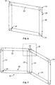
- FIGS. 6 and 7 show, respectively, an assembled frame 20, not according to the invention, with frame members 22 interconnected via tube connector assemblies 24 at the corners thereof.
- FIG. 7 shows two frames 20, not according to the invention, assembled into a display assembly 30 and wherein the two frames form an angled or open book configuration.
- the two frame members 22 can be connected at any desired angle, or at infinite angles, relative to one another.
- FIG. 8 shows a close-up view of the tube connector assemblies 24 assembled to frame members 22.
- the tenons 34 and magnetic assemblies 28 of the tube connector assemblies 24 are disposed within frame members 22.
- the magnets 60 are positioned adjacent each other when frames 20 are disposed each other to form display assembly 30.
- Each magnet 60 due to the free rotation mounting and configuration of the magnetic assembly 28, can orient itself to attract to an adjacent one of the magnets without loss of magnetic attractive force regardless of orientation of the frames because a positive side 64 rotates to be closest to a negative side 66 of an adjacent magnet as shown in FIG. 9 , and vice versa.
- the frames 20 become magnetically coupled and maintain the separate frames into a display assembly 30.
- FIG. 10 shows a cross section view of an embodiment of a magnetic assembly 128 according to the invention, disposed within a frame member 22 for coupling adjacent frames into the configuration shown in FIG. 7 .
- frames will be assembled with frame members 22 like that detailed above, which frame members are interconnected with junction connectors like those detailed above.
- the magnetic assembly 128 disclosed herein will be disposed in a corresponding frame member about mid-way between the ends of the frame member.
- Each magnetic assembly 128 includes a modified head portion 154 that rotatably accommodates two magnets 60.
- the head portion 154 includes two magnets 60, each of which is attached at opposite ends of the head portion on a respective post 58 constructed as in the embodiments disclosed in FIG. 5 , for example, and secured in like fashion.
- the magnetic assembly 128 can be secured in position within the hollow tubular opening of a structural member of the frame member 22 by any suitable method.
- One embodiment employs use of an magnet moved externally of the frame member 22 to magnetically position the magnetic assembly 128 at an approximate mid-point of the frame member in which the assembly has been inserted.
- the frame member 22 may be peened to create one or more indentation 68 that pinches and secures the head portion 154 within the frame member, leaving the magnets 60 to rotate with the frame member for proper self-orientation when brought into the magnetic influence of an adjacent magnet similarly positioned within an adjacent frame member of an adjacent frame or an accessory that is mounted on the frame.
- Other suitable methods may be employed, such as standard fasteners. For example, a screw, bolt, or pin may be inserted through the frame member and into the material of the head portion 154 to fasten the magnetic assembly 128 into position.
- frames 20 may be easily assembled into multi-frame display assemblies quickly, reversibly, without tools or other fasteners, by bringing two or more frames into close association or physically into contact, whereby the internal, freely-rotatable magnets self-align and create a magnetic attractive force that magnetically couples adjacent frames together. Reversing the coupling process by separating adjacent frames is simple, quick and requires no tools or manipulation of any fastening devices.
- the accessory bracket 70 is attachable to a tube 22 such as a cylindrical tube of a frame according to embodiments of the disclosure.
- the accessory bracket 70 includes at least a first attachment node 72.
- the accessory bracket 70 also includes a second attachment node 74.
- the first and second attachment nodes 72, 74 are connected to each other with an attachment arm 76.
- the bracket 70 includes an accessory support 78 that may be attached to or extend from the first attachment node 72.
- the relative positions of the first and second attachment nodes 72, 74 and the shape of the attachment arm 76 permit the accessory bracket 70 to releasably attach to tube 22.
- the accessory bracket 70 may be made of metal, plastic, composite materials or any suitable material. Parts of, or the entire, accessory bracket 70 may be provided with a grip coating 79 to increase the grip or feel of the part against the tube.
- the first and second attachment nodes 72, 74 may be provided with an elastomeric or rubber coating, a cork layer, felt material and the like.
- the accessory support 78 which in the illustrated embodiment may be a rod-shaped element, is configured to support one or more of a shelf, a panel, a display, one or more product, or any manufactured good or article supportable by the support and the tube 22.
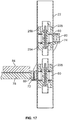
- FIG. 17 shows one example of a shelf 84 mounted to support 78 as an example of an accessory.
- the accessory support 78 may include any suitable shape, such as a rod, ring, hook, opening, teeth or any configuration that permits the support to hold, position, secure or otherwise support an accessory.
- the accessory support 78 may be integrated into a product display rack or other type of accessory.
- the shape and size of the attachment arm 76 positions the first and second attachment nodes 72, 74 on opposite sides of the tube 22.
- the attachment arm 76 may be arcuate and curved to match or complement the outer shape of tube 22.
- the attachment arm 76 positions the second attachment node 74 at a higher vertical position relative to the first attachment node 72.
- the first attachment node 72 thus acts as a fulcrum and the leverage imparted to the second attachment node 74 causes the first and second attachment node to pinch together against the tube 22, thereby securing the accessory bracket 70 in position on the tube, especially when the support 78 is weighted.
- the first and second attachment nodes 72, 74 include magnets or ferrous metal inserts 80 that utilize magnetic attraction to position and retain the accessory support 70 in a desired location on tube 22 in cooperation with at least one magnet 60 within the tube 22 (see FIG. 17 ).
- the inserts 80 are molded or housed within the nodes 72, 74. In one embodiment, the inserts 80 are disposed within the nodes 72, 74 so as to rotate and in another embodiment, the inserts are non-rotatable.
- the inserts 80 may each be a diametrically magnetized ring.
- FIG. 17 shows tube 22 with at least one magnetic assembly 228, not according to the invention, and in one embodiment a pair of magnetic assemblies 228, disposed in tube and spaced apart a distance that cooperates with the spacing of the first and second nodes 72, 74.
- the magnetic assemblies 228 are permitted to move freely along the interior of tube 22 or are secured in a selected position.
- Each of the magnetic assemblies 228 includes a diametrically magnetized ring shaped magnet 60 that is rotatable as in the above embodiments.
- the magnetic assemblies 228 may be fixed in a selected location when it is desired to locate the accessory support 70 in a predetermined position on tube 22.
- the magnetic assemblies 228 may be fixed according to the same method as the embodiment of FIG. 10 , i.e., by peening the tube with the assembly in position.
- the pair of magnetic assemblies 228 are permitted to move freely within the tube and thus provide for flexible location of the accessory support 70 along the length of the tube 22.
- Each magnetic assembly 228 may be constructed of a pair of head portions 254, 256.
- the two head portions 254, 256 are shaped and sized to be received within tube 22. When assembled the two head portions 254, 256 capture magnet 60 therebetween and are shaped and sized to permit free rotation of the magnet in place in the tube 22.
- the two head portions 254, 256 may be fastened together with a threaded fastener 63 that is received in one of the two head portions. The fastener 63 secures to a nut 82 that is held captive in the other of the two head portions.
- a shelf 84 is shown in cross section to show one example of how the accessory bracket supports an accessory on tube 22.
- the cantilever effect of the weight and position of the shelf 84 weights the support 78.
- the first node 72 is held on the first side of the tube 22 by the downward force of the support 78 and accessory 84.
- the node 72 acts as a fulcrum.
- the attachment arm 76 and first node 72 causes the second node 74 to press inwardly on the second side of the tube 22, opposite the first side and together the nodes 72, 74 pinch the tube, which causes the accessory bracket 70 to be releasably secured to the tube.
- the alignment of the magnets 60 and the inserts 80 ensures that the bracket 70 is located in a desired position.
- the magnets 60 and inserts 80 each rotate to a position that is magnetically mutually attractive, which assists in the positioning of the accessory bracket on the tube and helps keep it in place.
- FIGS. 18-21 show various views of the accessory bracket 70.
- First and second nodes 72, 74 each includes a magnet or magnetic insert 80.
- the insert 80 may be fixed in position or rotatable within the node.
- An attachment arm 76 interconnects the first node 72 to the second node 74 with a configuration that positions the second node 74 vertically above the first node 72 in the orientation of the figure and on a vertically oriented tube when connected thereto.
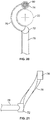
- FIG. 20 shows the curved configuration of the attachment arm 76 that permits the arm to wrap about the tube 22 and position the first and second nodes 72, 74 on opposing sides of the tube.
- the accessory support 78 extends from the first node 72 and away from the tube 22.
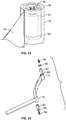
- FIG. 22 shows the second node 74 and the insert 80 in place within the material of the node.
- One embodiment of the second node 74 includes a compartment 88 in which the insert 80 is positioned.
- the insert 80 may be held in position with a fastener 84, such as a threaded screw.
- the fastener 84 may pass through a washer 86 that is fixed in position to close the compartment 88.
- the insert 80 may rotate within the compartment 88 or may be fixed in position.
- FIG. 23 shows an accessory bracket 70 in an exploded view with both first and second nodes 72, 74 constructed as in the embodiment of FIG. 22 .
Landscapes
- Engineering & Computer Science (AREA)
- Physics & Mathematics (AREA)
- General Physics & Mathematics (AREA)
- Theoretical Computer Science (AREA)
- General Engineering & Computer Science (AREA)
- Mechanical Engineering (AREA)
- Connection Of Plates (AREA)
- Devices For Indicating Variable Information By Combining Individual Elements (AREA)
Description
- The present disclosure relates to displays such as trade show displays, and to methods of coupling structural members and accessories in displays.
- Typically, displays use one or more frames, which are configured to carry rigid or flexible panels with artwork and/or messaging provided on the panels. The frames may be modular and may include two or more frames attached together with hardware, such as conventional fasteners and brackets, to form frame assemblies with a corresponding amount of display area while providing for easy transport when disassembled. Another attachment method may employ magnetic couplers fixed on the display frames that relies on the magnetic attraction of the magnets to hold adjacent frames together in position. The placement and pole orientation of the magnets on the frames determines the resultant configuration of the assemblies and requires careful alignment of the frames to securely couple the frames together. In this respect, existing displays assemble into predetermined configurations, and thus tend to lack flexibility as to geometry and ease of installation.
- One example of a previously proposed display utilizing magnetic couplers can be seen in
U.S. Patent 9,713,397 - Another example can be seen in
U.S. Patent 9,728,110 -
CN202093918 discloses a universal magnet type structure comprising a fixing connector and plates. The fixing connector is used for connecting at least two plates and comprises a long main member which is provided with four clamping tenons. The four clamping tenons are respectively inserted into tenon holes of the two plates so as to enable the fixing connector to be combined with the plurality of plates to form a square structure. A universal magnetic piece can be embedded in each clamping tenon and a plurality of the square structures can be combined by the principle of magnetism. - The present invention provides a display system including a first display frame including a plurality of frame members interconnected by junction connectors. The plurality of frame members each has a hollow interior. One or more diametrically polarized magnet is disposed to rotate freely within the hollow interior of at least one of the frame members. Each of the one or more magnets is disposed and rotatably supported within each of the at least one frame member at about a mid-point of the at least one frame member. The display system further includes at least one magnetic assembly sized and shaped to fit within the at least one frame member, the at least one magnetic assembly including one of the one or more magnets rotatably mounted thereon. The display system includes at least one magnetic assembly disposed within each of the plurality of frame members. Each at least one magnetic assembly includes a head portion and a pair of oppositely axially extending posts, each of the pair of posts supporting one of the one or more magnets.
- The display system may further include a plurality of diametrically polarized magnets, and wherein each of the plurality of frame members includes one of the plurality of diametrically polarized magnets rotatably disposed therein. Each of the plurality of frame members may have a tube configuration. Each of the junction connectors may include a connector body and at least one tenon extending therefrom, wherein the at least one tenon is sized and shaped to insert into a frame member. Each of the junction connectors may include a pair of tenons, each of the pair of tenons including one of the one or more magnets disposed thereon. The connector body may support a pair of tenons, wherein each of the pair of tenons is disposed on the connector body at an angle. The angle may be about 90 degrees.
- The display system may further include a magnetic assembly releasably secured to at least one tenon, the magnetic assembly including a head portion that is sized and shaped to attach to the at least one tenon and a post extending from the head portion that rotatably supports one of the one or more magnets.
- Each of the frame members may include one of the at least one magnetic assembly fixed therein. The at least one magnetic assembly may be fixed in place by peening the head portion in position by indenting the frame member.
- The display system may comprise a second display frame, the second display frame including a plurality of frame members interconnected by junction connectors, the plurality of frame members each having a hollow interior and one or more diametrically polarized magnets disposed to rotate freely within the hollow interior of at least one of the frame members of the second display frame. One or more magnets of the first display frame and the one or more magnets of the second display frame may be disposed to magnetically self-align and magnetically draw and couple the first display frame to the second display frame when the first display frame to the second display frame are positioned sufficiently close to each other.
- The display system may comprise at least one accessory bracket comprising a first node and a second node; one of a magnet and a ferrous insert disposed in at least one of the first and second nodes and configured to be magnetically coupled to one of the one or more diametrically polarized magnets of the display frame when positioned sufficiently close thereto; an attachment arm connecting the first node to the second node and configured to space apart the first node from the second node a distance that positions the first node and the second node on opposite sides on one of the plurality of frame members; and an accessory support extending from the first node and configured to support an accessory. The second node may be positioned vertically higher relative to the first node when the accessory bracket is positioned upon a vertically oriented one of the plurality of frame members. The first node and the second node may each include a diametrically polarized magnet that is configured to rotate freely.
- Further and alternative aspects and features of the disclosed principles will be appreciated from the following detailed description and the accompanying drawings.
-
-
FIG. 1 is an exploded, perspective view of a frame not according to the invention. -
FIG. 2 is a perspective view of a tube connector assembly not according to the invention. -
FIG. 3 is an exploded, perspective view of the tube connector assembly ofFIG. 2 . -
FIG. 4 is a perspective view of a magnetic assembly not according to the invention. -
FIG. 5 is an exploded, perspective view of the magnetic assembly ofFIG. 4 . -
FIG. 6 is a perspective view of an assembled frame not according to the invention. -
FIG. 7 is a perspective view of two of the frames ofFIG. 6 coupled together. -
FIG. 8 is a cut-away, partial perspective view of two adjacent frames shown inFIG. 7 , with adjacent tube connector assemblies in position to be coupled magnetically. -
FIG. 9 is a close-up view of two adjacent magnetic assemblies to illustrate the magnets in a coupled orientation. -
FIG. 10 is a cross section side view of an embodiment of a magnetic assembly according to the invention, secured inside a frame member. -
FIG. 11 is a perspective front view of an accessory bracket attached to a tube. -
FIG. 12 is a cutaway view of the accessory bracket and tube ofFIG. 11 . -
FIG. 13 is a perspective rear view of an accessory bracket attached to a tube. -
FIG. 14 is a cutaway view of the accessory bracket and tube ofFIG. 13 . -
FIG. 15 is a perspective side view of an accessory bracket attached to a tube. -
FIG. 16 is a cutaway view of the accessory bracket and tube ofFIG. 15 . -
FIG. 17 is a section view of an accessory bracket attached to a tube with magnetic assemblies not according to the invention. -
FIG. 18 is a perspective view of an accessory bracket. -
FIG. 19 is a cutaway view of the accessory bracket ofFIG. 18 . -
FIG. 20 is a top view of an accessory bracket disposed about a tube. -
FIG. 21 is a side view of the accessory bracket ofFIG. 20 . -
FIG. 22 is a cutaway perspective view of a portion of an accessary bracket. -
FIG. 23 is an exploded view of the accessory bracket ofFIG. 21 . - Reference will now be made in detail to specific embodiments or features, examples of which are illustrated in the accompanying drawings. Wherever possible, corresponding or similar reference numbers will be used throughout the drawings to refer to the same or corresponding parts. Moreover, references to various elements described herein, are made collectively or individually when there may be more than one element of the same type. However, such references are merely exemplary in nature. It may be noted that any reference to elements in the singular may also be construed to relate to the plural and vice-versa without limiting the scope of the disclosure to the exact number or type of such elements unless set forth explicitly in the appended claims. The terms configured and configuration may be used herein to refer to a specified structural size and shape.
-
FIG. 1 illustrates asingle frame 20 which is not according to the invention. Theframe 20 may be constructed offrame members 22 interconnected bytube connector assemblies 24. Eachtube connector assembly 24 includes ajunction connector 26 and one or moremagnetic assembly 28. - Two or
more frames 20 may be coupled together through magnetic interaction of adjacentmagnetic assemblies 28 disposed within display assemblies 30 (FIG. 7 ). It will be understood that once assembled, eachframe 20 may be provided with one or more display panel or display element (not shown) with text, and/or images or any desirable information displayed thereon as is known in the art, for example on a substrate, a fabric, a rigid panel, or electronic displays. Advantageously, the internal placement of the magnetic elements within the frames permits the unobstructed outer profile of the frames to be preserved so as not to interrupt the graphics appearing on the external surfaces of the frames. Alternatively, two or more of theframes 20 may be provided with a single panel or display element that is supported by the coupled frames. - Each
frame member 22 may be an elongate, hollow member of any suitable shape, cross sectional profile and extent.Frame members 22 may be constructed of metal, plastic, composites or any suitable material. One embodiment contemplatesframe members 22 made of aluminum. Eachframe member 22 may be cylindrical and hollow and is sized and shaped to receive part or all of atube connector assembly 24 in eachopen end 30 of each frame member. The size and shape of eachframe member 22 defines an opening at each open frame member end 33 with aninternal diameter 31 that receives part of ajunction connector 26 and in some embodiments also amagnetic assembly 28 therein to provide a secure fit of the frame member andtube connector assembly 24 at the open end. It will be understood that in embodiments where theframe member 22 is not cylindrical, that thetube connector assembly 24 will be likewise configured to be a secure fit thereto. In one contemplated example, the frame member may have a hexagonal or octagonal cross section. In the illustrated embodiment, theopen frame members 33 are tubular with a hollow interior that extends along the entire length of the frame member around a centerline. - Turning to
FIGS. 2-5 , not according to the invention, eachtube connector assembly 24 may include ajunction connector 26 and amagnetic assembly 28 attached to the junction connector.Junction connector 26 may be made of any suitable material, for example metal, plastic, or composite materials. Themagnetic assembly 28 may be releasably connected to thejunction connector 26 by way of any suitable connection. Alternatively, themagnetic assembly 28 may be permanently connected to thejunction connector 26, by press fit, an adhesive, or any suitable securement. - The
junction connector 26 includes aconnector body 32 and may include a pair of connector tenons 34 extending from the connector body. Alternatively, theconnector body 32 may include more than two extending tenons, for example in a X, Y, Z orthogonal configuration. These tenons fit within mortise holes, which in the illustrated embodiments are made from the hollow interiors of the frame members. - The
connector body 32 may be in the shape of an elbow and may supporttenons 34 in an angled or straight configuration. In one embodiment, theconnector body 32 supports tenons 34 at an angle of about 90 degrees. Thebody 32 may include ashoulder 36 at the junction of the body and tenons 34. Theshoulder 36 forms a stop for aframe member 22 when inserted over one of thetenons 34 and advanced toward thebody 32. In an embodiment where theframe member 22 is cylindrical, theshoulder 36 is annular and extends radially. - The
tenons 34 may be cylindrical and each with an axis A. As shown, the axis A coincides with the centerline of theopen frame members 31 when thetube connector assembly 24 is installed into anopen frame member 31. The two axes A of the illustrated embodiment are oriented 90 degrees relative to each other as a result of the extending alignment of thetenons 34 on theconnector body 32. In one embodiment, where thetenons 34 are arranged to yield axes that are aligned with each other, i.e., wherein theconnector body 32 is straight, the angle between the tenons may be considered to be zero or 180 degrees. In one embodiment, thetenons 34 have identical axes, and in another embodiment, the tenons may be offset from each other, wherein the axes are parallel to each other but laterally displaced and thus not the same. - The
tenons 34 may include one ormore opening 38. Theopenings 38 may be circular or any suitable shape for receiving a corresponding, biasedtab 40 located on themagnetic assembly 28. When themagnetic assembly 28 is inserted into atenon 34 thetab 40 is either manually depressed or is configured to be depressed by the tenon, and when the tab becomes aligned with one of theopenings 38 is springs into the opening where it makes a locking contact with the edge of the opening. In this manner, themagnetic assembly 28 is secured to thetenon 34. Causing thetab 40 to be depressed permits disengagement of the tab from theopening 38 and disassembly of themagnetic assembly 28 from thejunction connector 26. - The
tenon 34 may also include a biased tube engagement mechanism 42. The tube engagement mechanism 42 may include a spring loadedbutton 44 that engages a hole (not shown) in aframe member 22 in much the same fashion astab 40 engages opening 38 for attaching a frame member to atube connector assembly 24. - The
tenons 34 each may further include at least oneguide ridge 46 that extends longitudinally along the axis A of the tenon. Theguide ridge 46 functions to guide theframe member 22 as the frame member is drawn over the tenon and functions to space the frame member from theouter surface 48 of the tenon. Thus, thetab 40 may be positioned in an engagement position relative to theopening 38 and slightly proud of theouter surface 48 so that the tab may be depressed manually if needed. Furthermore, the space provided or at least a guide function eases theframe member 22 onto thetenon 34 with less friction than a plain joint and while providing easy passage of air through the joint. - Each
magnetic assembly 28 may include arod portion 48, which may be configured to fit into an interior 50 of atenon 34. Therod portion 48 includes thetab 40. Thetab 40 may be formed on the end of aflexible leg 52, which provides the bias or spring function of the tab. Therod portion 48 widens to ahead portion 54, which is radially wider than the rod portion. Ashoulder 56 is formed between therod portion 48 and thehead portion 54 that is sized and shaped to abut the end of thetenon 34 when the rod portion is fully inserted into the interior 50 of the tenon and thetab 40 engages theopening 38. - Referring to
FIG. 5 , not according to the invention, on the end of thehead portion 54, opposite therod portion 48, is formed acylindrical post 58. Thepost 58 has a radial diameter that is less that of thehead portion 54 and is sized and shaped to rotatably receive amagnet 60 thereupon. Themagnet 60 may be held on thepost 58 with a fastener 63 and washer 65 or any suitable fastening mechanism, provided the fastening mechanism permits free rotation of themagnet 60 on thepost 58 and about the axis A. - The
magnet 60 is sized and shaped to have a radial clearance within the inner diameter or space of frame member in which it is installed such that the magnet can rotate within theframe member 22 when theframe 20 is assembled. Accordingly, themagnet 60 freely orients in a manner so as to self align and generate attractive forces in combination with an adjacentmagnetic assembly 28 of anadjacent frame 20. In other words, the size and shape of themagnet 60 permits free movement on thepost 58 and inside aframe member 22 when assembled to amagnetic assembly 28 and atube connector assembly 24. - The
magnet 60 is a diametrically magnetized ring shape (vs. an axially magnetized ring or, in general, an axially polarized magnet such as in the Shields and Taylor references discussed previously), which has its North and South poles disposed on diametrically opposite locations around the ring shape. Themagnet 60 may be cylindrical with anaxial bore 62 that rotatably fits on thepost 58. Themagnet 60 may rotate such that the polarity of the magnet (i.e., left and right side of the ring has different polarity vs. the polar axial ends) can orient itself based on nearby magnetic fields and polarity as will be shown in more detail hereinbelow. Referring toFIG. 5 , for example, the upperleft side 64 ofmagnet 60 may be positive and the lowerright side 66 may be negative. -
FIGS. 6 and 7 show, respectively, an assembledframe 20, not according to the invention, withframe members 22 interconnected viatube connector assemblies 24 at the corners thereof.FIG. 7 shows twoframes 20, not according to the invention, assembled into adisplay assembly 30 and wherein the two frames form an angled or open book configuration. Advantageously, the twoframe members 22 can be connected at any desired angle, or at infinite angles, relative to one another.FIG. 8 shows a close-up view of thetube connector assemblies 24 assembled to framemembers 22. Thejunction connector 26 portion of the tube connector assemblies for the corner of theframe 20. Thetenons 34 andmagnetic assemblies 28 of thetube connector assemblies 24 are disposed withinframe members 22. Themagnets 60 are positioned adjacent each other when frames 20 are disposed each other to formdisplay assembly 30. Eachmagnet 60, due to the free rotation mounting and configuration of themagnetic assembly 28, can orient itself to attract to an adjacent one of the magnets without loss of magnetic attractive force regardless of orientation of the frames because apositive side 64 rotates to be closest to anegative side 66 of an adjacent magnet as shown inFIG. 9 , and vice versa. Thus, theframes 20 become magnetically coupled and maintain the separate frames into adisplay assembly 30. -
FIG. 10 shows a cross section view of an embodiment of amagnetic assembly 128 according to the invention, disposed within aframe member 22 for coupling adjacent frames into the configuration shown inFIG. 7 . It will be understood that frames will be assembled withframe members 22 like that detailed above, which frame members are interconnected with junction connectors like those detailed above. However, themagnetic assembly 128 disclosed herein will be disposed in a corresponding frame member about mid-way between the ends of the frame member. - Each
magnetic assembly 128 includes a modifiedhead portion 154 that rotatably accommodates twomagnets 60. According to the invention, thehead portion 154 includes twomagnets 60, each of which is attached at opposite ends of the head portion on arespective post 58 constructed as in the embodiments disclosed inFIG. 5 , for example, and secured in like fashion. - The
magnetic assembly 128 can be secured in position within the hollow tubular opening of a structural member of theframe member 22 by any suitable method. One embodiment employs use of an magnet moved externally of theframe member 22 to magnetically position themagnetic assembly 128 at an approximate mid-point of the frame member in which the assembly has been inserted. Theframe member 22 may be peened to create one ormore indentation 68 that pinches and secures thehead portion 154 within the frame member, leaving themagnets 60 to rotate with the frame member for proper self-orientation when brought into the magnetic influence of an adjacent magnet similarly positioned within an adjacent frame member of an adjacent frame or an accessory that is mounted on the frame. Other suitable methods may be employed, such as standard fasteners. For example, a screw, bolt, or pin may be inserted through the frame member and into the material of thehead portion 154 to fasten themagnetic assembly 128 into position. - After assembly, frames 20 may be easily assembled into multi-frame display assemblies quickly, reversibly, without tools or other fasteners, by bringing two or more frames into close association or physically into contact, whereby the internal, freely-rotatable magnets self-align and create a magnetic attractive force that magnetically couples adjacent frames together. Reversing the coupling process by separating adjacent frames is simple, quick and requires no tools or manipulation of any fastening devices.
- Turning to
FIGS. 11-23 , an embodiment of anaccessory bracket 70 is shown. Theaccessory bracket 70 is attachable to atube 22 such as a cylindrical tube of a frame according to embodiments of the disclosure. Theaccessory bracket 70 includes at least afirst attachment node 72. In the illustrated embodiment, theaccessory bracket 70 also includes asecond attachment node 74. The first andsecond attachment nodes attachment arm 76. Thebracket 70 includes anaccessory support 78 that may be attached to or extend from thefirst attachment node 72. The relative positions of the first andsecond attachment nodes attachment arm 76 permit theaccessory bracket 70 to releasably attach totube 22. Theaccessory bracket 70 may be made of metal, plastic, composite materials or any suitable material. Parts of, or the entire,accessory bracket 70 may be provided with agrip coating 79 to increase the grip or feel of the part against the tube. For example, the first andsecond attachment nodes - The
accessory support 78, which in the illustrated embodiment may be a rod-shaped element, is configured to support one or more of a shelf, a panel, a display, one or more product, or any manufactured good or article supportable by the support and thetube 22.FIG. 17 shows one example of ashelf 84 mounted to support 78 as an example of an accessory. Theaccessory support 78 may include any suitable shape, such as a rod, ring, hook, opening, teeth or any configuration that permits the support to hold, position, secure or otherwise support an accessory. Moreover, theaccessory support 78 may be integrated into a product display rack or other type of accessory. - The shape and size of the
attachment arm 76 positions the first andsecond attachment nodes tube 22. Theattachment arm 76 may be arcuate and curved to match or complement the outer shape oftube 22. Theattachment arm 76 positions thesecond attachment node 74 at a higher vertical position relative to thefirst attachment node 72. Thefirst attachment node 72 thus acts as a fulcrum and the leverage imparted to thesecond attachment node 74 causes the first and second attachment node to pinch together against thetube 22, thereby securing theaccessory bracket 70 in position on the tube, especially when thesupport 78 is weighted. - The first and
second attachment nodes accessory support 70 in a desired location ontube 22 in cooperation with at least onemagnet 60 within the tube 22 (seeFIG. 17 ). Theinserts 80 are molded or housed within thenodes inserts 80 are disposed within thenodes inserts 80 may each be a diametrically magnetized ring. -
FIG. 17 showstube 22 with at least onemagnetic assembly 228, not according to the invention, and in one embodiment a pair ofmagnetic assemblies 228, disposed in tube and spaced apart a distance that cooperates with the spacing of the first andsecond nodes magnetic assemblies 228 are permitted to move freely along the interior oftube 22 or are secured in a selected position. - Each of the
magnetic assemblies 228 includes a diametrically magnetized ring shapedmagnet 60 that is rotatable as in the above embodiments. Themagnetic assemblies 228 may be fixed in a selected location when it is desired to locate theaccessory support 70 in a predetermined position ontube 22. Themagnetic assemblies 228 may be fixed according to the same method as the embodiment ofFIG. 10 , i.e., by peening the tube with the assembly in position. Alternatively, the pair ofmagnetic assemblies 228 are permitted to move freely within the tube and thus provide for flexible location of theaccessory support 70 along the length of thetube 22. - Each
magnetic assembly 228 may be constructed of a pair ofhead portions head portions tube 22. When assembled the twohead portions capture magnet 60 therebetween and are shaped and sized to permit free rotation of the magnet in place in thetube 22. The twohead portions - In the embodiment shown in
FIG. 17 , ashelf 84 is shown in cross section to show one example of how the accessory bracket supports an accessory ontube 22. The cantilever effect of the weight and position of theshelf 84 weights thesupport 78. Thefirst node 72 is held on the first side of thetube 22 by the downward force of thesupport 78 andaccessory 84. Thenode 72 acts as a fulcrum. Theattachment arm 76 andfirst node 72 causes thesecond node 74 to press inwardly on the second side of thetube 22, opposite the first side and together thenodes accessory bracket 70 to be releasably secured to the tube. The alignment of themagnets 60 and theinserts 80 ensures that thebracket 70 is located in a desired position. When theaccessory bracket 70 is attached to thetube 22, themagnets 60 and inserts 80 each rotate to a position that is magnetically mutually attractive, which assists in the positioning of the accessory bracket on the tube and helps keep it in place. -
FIGS. 18-21 show various views of theaccessory bracket 70. First andsecond nodes magnetic insert 80. Theinsert 80 may be fixed in position or rotatable within the node. Anattachment arm 76 interconnects thefirst node 72 to thesecond node 74 with a configuration that positions thesecond node 74 vertically above thefirst node 72 in the orientation of the figure and on a vertically oriented tube when connected thereto.FIG. 20 shows the curved configuration of theattachment arm 76 that permits the arm to wrap about thetube 22 and position the first andsecond nodes accessory support 78 extends from thefirst node 72 and away from thetube 22. -
FIG. 22 shows thesecond node 74 and theinsert 80 in place within the material of the node. One embodiment of thesecond node 74 includes acompartment 88 in which theinsert 80 is positioned. Theinsert 80 may be held in position with afastener 84, such as a threaded screw. Thefastener 84 may pass through awasher 86 that is fixed in position to close thecompartment 88. Theinsert 80 may rotate within thecompartment 88 or may be fixed in position.FIG. 23 shows anaccessory bracket 70 in an exploded view with both first andsecond nodes FIG. 22 .
Claims (10)
- A display system, comprising:a first display frame (20) including a plurality of frame members (22) interconnected by junction connectors (26), the plurality of frame members (22) each having a hollow interior; andone or more diametrically polarized magnets (60) disposed to rotate freely within the hollow interior of at least one of the frame members (22),wherein each of the one or more magnets (60) is disposed and rotatably supported within each of the at least one frame member (22) at about a mid-point of the at least one frame member (22).wherein the display system further includes at least one magnetic assembly (128) sized and shaped to fit within the at least one frame member (22), the at least one magnetic assembly (28) including one of the one or more magnets (60) rotatably mounted thereon, and the display system includes at least one magnetic assembly (28) disposed within each of the plurality of frame members (22),characterised in that each at least one magnetic assembly includes a head portion (154) and a pair of oppositely axially extending posts (58), each of the pair of posts supporting one of the one or more magnets (60).
- The display system of claim 1, further including a plurality of diametrically polarized magnets (60), and wherein each of the plurality of frame members (22) includes one of the plurality of diametrically polarized magnets (60) rotatably disposed therein and/or wherein each of the plurality of frame members (22) has a tube configuration.
- The display system of claim 1 or claim 2, wherein each of the junction connectors (26) includes a connector body (32) and at least one tenon (34) extending therefrom, wherein the at least one tenon (34) is sized and shaped to insert into a frame member (22).
- The display system of claim 3, wherein each of the junction connectors (26) includes a pair of tenons (34), each of the pair of tenons (34) including one of the one or more magnets (60) disposed thereon.
- The display system of claim 4, wherein the connector body (32) supports the pair of tenons (34), wherein each of the pair of tenons (34) is disposed on the connector body (32) at an angle, wherein the angle is optionally about 90 degrees.
- The display system of claim 3, further including a magnetic assembly (28) releasably secured to the at least one tenon (34), the magnetic assembly (28) including a head portion (54) that is sized and shaped to attach to the at least one tenon (34) and a post (58) extending from the head portion (54) that rotatably supports one of the one or more magnets (60).
- The display system of any preceding claim, wherein each of the frame members includes one of the at least one magnetic assembly (128) fixed therein or wherein the at least one magnetic assembly (128) is fixed in place by peening the head portion (154) in position by indenting the frame member.
- The display system of any preceding claim, comprising a second display frame, the second display frame (20) including a plurality of frame members (22) interconnected by junction connectors (26), the plurality of frame members (22) each having a hollow interior and one or more diametrically polarized magnets (60) disposed to rotate freely within the hollow interior of at least one of the frame members (22) of the second display frame (20) and, optionally, wherein the one or more magnets (60) of the first display frame (20) and the one or more magnets (60) of the second display frame (20) are disposed to magnetically self-align and magnetically draw and couple the first display frame (20) to the second display frame (20) when the first display frame (20) to the second display frame (20) are positioned sufficiently close to each other.
- The display system according to claim 1, further comprising:
at least one accessory bracket (70) comprising:a first node (72) and a second node (74);one of a magnet and a ferrous insert (80) disposed in at least one of the first and second nodes (72, 74) and configured to be magnetically coupled to one of the one or more diametrically polarized magnets (60) of the display frame (20) when positioned sufficiently close thereto;an attachment arm (76) connecting the first node (72) to the second node (74) and configured to space apart the first node (72) from the second node(74) a distance that positions the first node (72) and the second node (74) on opposite sides on one of the plurality of frame members (22); andan accessory support (78) extending from the first node (72) and configured to support an accessory (84). - The display system of claim 9, wherein the second node (74) is positioned vertically higher relative to the first node (72) when the accessory bracket (70) is positioned upon a vertically oriented one of the plurality of frame members (22) and/or wherein the first node (72) and the second node (74) each include a diametrically polarized magnet that is configured to rotate freely.
Applications Claiming Priority (1)
| Application Number | Priority Date | Filing Date | Title |
|---|---|---|---|
| US15/728,791 US10217388B1 (en) | 2017-10-10 | 2017-10-10 | Display System |
Publications (2)
| Publication Number | Publication Date |
|---|---|
| EP3469951A1 EP3469951A1 (en) | 2019-04-17 |
| EP3469951B1 true EP3469951B1 (en) | 2020-11-04 |
Family
ID=63452435
Family Applications (1)
| Application Number | Title | Priority Date | Filing Date |
|---|---|---|---|
| EP18191802.0A Active EP3469951B1 (en) | 2017-10-10 | 2018-08-30 | Display system |
Country Status (2)
| Country | Link |
|---|---|
| US (1) | US10217388B1 (en) |
| EP (1) | EP3469951B1 (en) |
Families Citing this family (5)
| Publication number | Priority date | Publication date | Assignee | Title |
|---|---|---|---|---|
| KR101865564B1 (en) * | 2018-03-21 | 2018-06-08 | 황은태 | Exhibition booth module and the method of installation |
| GB2598322B (en) * | 2020-08-25 | 2022-08-24 | Everplay Labs Ltd | System, panel and method |
| USD1045260S1 (en) * | 2021-01-02 | 2024-10-01 | Brian Tumpane | Garden hose attached washing tool |
| EP4627225A1 (en) * | 2022-12-01 | 2025-10-08 | Jason Jennings | Structural support design system |
| US11942001B1 (en) * | 2023-10-18 | 2024-03-26 | Thrones Llc | Banner stand |
Family Cites Families (28)
| Publication number | Priority date | Publication date | Assignee | Title |
|---|---|---|---|---|
| US2970388A (en) * | 1956-05-07 | 1961-02-07 | Edward H Yonkers | Education device |
| US4912864A (en) * | 1988-12-12 | 1990-04-03 | Price Ruth A | Magnetized picture frame |
| US5588240A (en) | 1994-03-18 | 1996-12-31 | Zilliox; Kent | Interlocking picture frame |
| DE19652969C1 (en) * | 1996-12-19 | 1998-04-02 | Burkhardt Leitner | Support space frame connecting nodes and struts |
| US5826397A (en) | 1997-03-25 | 1998-10-27 | Armold; Charles K. | Collapsible framework for trade show display |
| ITMI20010010U1 (en) | 2001-01-09 | 2002-07-09 | Vicentelli Claudio | PERFECT ASSEMBLY OF MAGNETIC ANCHORAGE MODULES FOR THE REALIZATION OF STABLE RETICULAR STRUCTURES |
| US7802582B2 (en) * | 2006-07-10 | 2010-09-28 | Evrio, Inc. | System for concealment and shelter with structure for rapid setup and tight skin |
| US20050160652A1 (en) | 2004-01-23 | 2005-07-28 | Moody Thomas B. | Modular display frame |
| KR100695293B1 (en) * | 2006-09-13 | 2007-03-14 | 김종성 | Magnetic Block Toys |
| US8070550B2 (en) * | 2006-09-13 | 2011-12-06 | Edtoy Co., Ltd. | Block for building a toy |
| US8128452B2 (en) * | 2006-09-13 | 2012-03-06 | Edtoy Co., Ltd. | Building block |
| ITMI20061956A1 (en) * | 2006-10-12 | 2007-01-11 | Claudio Vicentelli | SET OF BLOCKS WITH MAGNETIC ELEMENTS OF ANCHORING MOBILE TO BUILD GAMES |
| US20100251659A1 (en) | 2006-11-29 | 2010-10-07 | Hughes Robert P | Hubs and reconfigurable frames |
| US7437846B2 (en) | 2007-02-26 | 2008-10-21 | Natali Franco | Dual window display box |
| US20090100732A1 (en) | 2007-10-19 | 2009-04-23 | Concept Workshop Worldwide, Llc | Magnetic display device |
| US8146872B2 (en) | 2008-04-10 | 2012-04-03 | L S Mold, Inc. | Display attachment apparatus |
| US20100229439A1 (en) | 2009-03-12 | 2010-09-16 | Trevor Elliot | Magnetic modular assembly system for picture frame that includes specialized photography sequence and method of use |
| CN202093918U (en) * | 2010-09-14 | 2011-12-28 | 内湖电机有限公司 | Universal magnetic structure and fixed coupler |
| DE102011012088A1 (en) | 2011-02-23 | 2012-08-23 | Bernhard Doll | Visualization system has a magnetic or magnetizable information panel that is provided with exchangeable frame and plate which is magnetically fixed in frame |
| SE535650C2 (en) * | 2011-02-25 | 2012-10-30 | Expand Int Ab | A collapsible, flexible display system |
| JP5563510B2 (en) * | 2011-04-01 | 2014-07-30 | 株式会社マグナ | Universal joining device |
| US20120285060A1 (en) | 2011-05-12 | 2012-11-15 | Design Ideas, Ltd. | Picture frames |
| KR101458692B1 (en) * | 2013-03-05 | 2014-11-05 | 정 석 윤 | Magnetic Puzzle |
| US9728110B2 (en) | 2014-03-14 | 2017-08-08 | Vomela Specialty Company | Portable exhibit display with magnetic accessory mounts |
| US9339129B1 (en) | 2014-03-14 | 2016-05-17 | Vomela Specialty Company | Portable exhibit display with magnetic accessory mounts |
| US20160074766A1 (en) * | 2014-09-11 | 2016-03-17 | Click-Block Corporation | Surface structure for combining block of block toy having magnet inside |
| US9408482B2 (en) | 2014-09-11 | 2016-08-09 | Bonnie Northrop Nesbitt | Modular picture display system |
| US9713397B2 (en) | 2014-11-14 | 2017-07-25 | Hallmark Cards, Incorporated | Modular display frames and system for magnetically coupled arrangements |
-
2017
- 2017-10-10 US US15/728,791 patent/US10217388B1/en active Active - Reinstated
-
2018
- 2018-08-30 EP EP18191802.0A patent/EP3469951B1/en active Active
Non-Patent Citations (1)
| Title |
|---|
| None * |
Also Published As
| Publication number | Publication date |
|---|---|
| EP3469951A1 (en) | 2019-04-17 |
| US10217388B1 (en) | 2019-02-26 |
Similar Documents
| Publication | Publication Date | Title |
|---|---|---|
| US10217388B1 (en) | Display System | |
| US10221994B2 (en) | Modular mounting system | |
| US11085183B2 (en) | Display system | |
| US10941899B2 (en) | Mounting track for retaining a mount assembly | |
| US8480044B2 (en) | Omni-direction rotatable dual-cup suction device | |
| US10327545B2 (en) | Display support system | |
| US6854238B2 (en) | Structural connection system for frameworks | |
| CA2089843C (en) | Joint for detachable connection of structural members | |
| US8020328B2 (en) | Connecting elements for construction | |
| US9175801B2 (en) | Wheel apparatus | |
| US20250361955A1 (en) | Flexible air duct systems and methods of installation and use thereof | |
| US20140224947A1 (en) | Electronic Device Holder | |
| US11221102B2 (en) | Column mounting bracket | |
| ES2345855T3 (en) | MULTICONFIGURABLE TUBULAR PRESENTATION SYSTEM. | |
| JP2004521696A (en) | Member for coupling module for constructing stable grid structure with magnetic anchorage | |
| US20140115861A1 (en) | Locking device for detachably fixing parts of constructional elements together | |
| US20190274453A1 (en) | Mounting device for attaching a display device, a picture frame, or the like to a supporting structure | |
| JP2004500523A (en) | Longitudinal clamp for structural members | |
| WO2013173660A2 (en) | Permanent magnet panel fastener | |
| US20160249750A1 (en) | Portable Exhibit Display with Magnetic Accessory Mounts | |
| US10646059B1 (en) | Suspended segmented display array with low visibility hardware | |
| US20050087308A1 (en) | Office cubicle door | |
| US3804358A (en) | Fastener assembly | |
| US6874737B1 (en) | Universal fixture system and base therefor | |
| GB2491160A (en) | Joint member for a space frame and panels |
Legal Events
| Date | Code | Title | Description |
|---|---|---|---|
| PUAI | Public reference made under article 153(3) epc to a published international application that has entered the european phase |
Free format text: ORIGINAL CODE: 0009012 |
|
| STAA | Information on the status of an ep patent application or granted ep patent |
Free format text: STATUS: THE APPLICATION HAS BEEN PUBLISHED |
|
| AK | Designated contracting states |
Kind code of ref document: A1 Designated state(s): AL AT BE BG CH CY CZ DE DK EE ES FI FR GB GR HR HU IE IS IT LI LT LU LV MC MK MT NL NO PL PT RO RS SE SI SK SM TR |
|
| AX | Request for extension of the european patent |
Extension state: BA ME |
|
| STAA | Information on the status of an ep patent application or granted ep patent |
Free format text: STATUS: REQUEST FOR EXAMINATION WAS MADE |
|
| 17P | Request for examination filed |
Effective date: 20191015 |
|
| RBV | Designated contracting states (corrected) |
Designated state(s): AL AT BE BG CH CY CZ DE DK EE ES FI FR GB GR HR HU IE IS IT LI LT LU LV MC MK MT NL NO PL PT RO RS SE SI SK SM TR |
|
| GRAP | Despatch of communication of intention to grant a patent |
Free format text: ORIGINAL CODE: EPIDOSNIGR1 |
|
| STAA | Information on the status of an ep patent application or granted ep patent |
Free format text: STATUS: GRANT OF PATENT IS INTENDED |
|
| INTG | Intention to grant announced |
Effective date: 20200511 |
|
| RIC1 | Information provided on ipc code assigned before grant |
Ipc: F16B 12/44 20060101ALN20200424BHEP Ipc: A47B 47/00 20060101ALN20200424BHEP Ipc: A47F 5/13 20060101ALI20200424BHEP Ipc: A47B 57/30 20060101AFI20200424BHEP Ipc: F16B 12/50 20060101ALI20200424BHEP Ipc: G09F 15/00 20060101ALN20200424BHEP |
|
| GRAS | Grant fee paid |
Free format text: ORIGINAL CODE: EPIDOSNIGR3 |
|
| GRAA | (expected) grant |
Free format text: ORIGINAL CODE: 0009210 |
|
| STAA | Information on the status of an ep patent application or granted ep patent |
Free format text: STATUS: THE PATENT HAS BEEN GRANTED |
|
| AK | Designated contracting states |
Kind code of ref document: B1 Designated state(s): AL AT BE BG CH CY CZ DE DK EE ES FI FR GB GR HR HU IE IS IT LI LT LU LV MC MK MT NL NO PL PT RO RS SE SI SK SM TR |
|
| REG | Reference to a national code |
Ref country code: GB Ref legal event code: FG4D |
|
| REG | Reference to a national code |
Ref country code: CH Ref legal event code: EP |
|
| REG | Reference to a national code |
Ref country code: AT Ref legal event code: REF Ref document number: 1329701 Country of ref document: AT Kind code of ref document: T Effective date: 20201115 |
|
| REG | Reference to a national code |
Ref country code: IE Ref legal event code: FG4D |
|
| REG | Reference to a national code |
Ref country code: DE Ref legal event code: R096 Ref document number: 602018009358 Country of ref document: DE |
|
| REG | Reference to a national code |
Ref country code: NL Ref legal event code: MP Effective date: 20201104 |
|
| REG | Reference to a national code |
Ref country code: AT Ref legal event code: MK05 Ref document number: 1329701 Country of ref document: AT Kind code of ref document: T Effective date: 20201104 |
|
| PG25 | Lapsed in a contracting state [announced via postgrant information from national office to epo] |
Ref country code: RS Free format text: LAPSE BECAUSE OF FAILURE TO SUBMIT A TRANSLATION OF THE DESCRIPTION OR TO PAY THE FEE WITHIN THE PRESCRIBED TIME-LIMIT Effective date: 20201104 Ref country code: PT Free format text: LAPSE BECAUSE OF FAILURE TO SUBMIT A TRANSLATION OF THE DESCRIPTION OR TO PAY THE FEE WITHIN THE PRESCRIBED TIME-LIMIT Effective date: 20210304 Ref country code: FI Free format text: LAPSE BECAUSE OF FAILURE TO SUBMIT A TRANSLATION OF THE DESCRIPTION OR TO PAY THE FEE WITHIN THE PRESCRIBED TIME-LIMIT Effective date: 20201104 Ref country code: GR Free format text: LAPSE BECAUSE OF FAILURE TO SUBMIT A TRANSLATION OF THE DESCRIPTION OR TO PAY THE FEE WITHIN THE PRESCRIBED TIME-LIMIT Effective date: 20210205 Ref country code: NO Free format text: LAPSE BECAUSE OF FAILURE TO SUBMIT A TRANSLATION OF THE DESCRIPTION OR TO PAY THE FEE WITHIN THE PRESCRIBED TIME-LIMIT Effective date: 20210204 |
|
| PG25 | Lapsed in a contracting state [announced via postgrant information from national office to epo] |
Ref country code: BG Free format text: LAPSE BECAUSE OF FAILURE TO SUBMIT A TRANSLATION OF THE DESCRIPTION OR TO PAY THE FEE WITHIN THE PRESCRIBED TIME-LIMIT Effective date: 20210204 Ref country code: SE Free format text: LAPSE BECAUSE OF FAILURE TO SUBMIT A TRANSLATION OF THE DESCRIPTION OR TO PAY THE FEE WITHIN THE PRESCRIBED TIME-LIMIT Effective date: 20201104 Ref country code: PL Free format text: LAPSE BECAUSE OF FAILURE TO SUBMIT A TRANSLATION OF THE DESCRIPTION OR TO PAY THE FEE WITHIN THE PRESCRIBED TIME-LIMIT Effective date: 20201104 Ref country code: LV Free format text: LAPSE BECAUSE OF FAILURE TO SUBMIT A TRANSLATION OF THE DESCRIPTION OR TO PAY THE FEE WITHIN THE PRESCRIBED TIME-LIMIT Effective date: 20201104 Ref country code: IS Free format text: LAPSE BECAUSE OF FAILURE TO SUBMIT A TRANSLATION OF THE DESCRIPTION OR TO PAY THE FEE WITHIN THE PRESCRIBED TIME-LIMIT Effective date: 20210304 Ref country code: ES Free format text: LAPSE BECAUSE OF FAILURE TO SUBMIT A TRANSLATION OF THE DESCRIPTION OR TO PAY THE FEE WITHIN THE PRESCRIBED TIME-LIMIT Effective date: 20201104 Ref country code: AT Free format text: LAPSE BECAUSE OF FAILURE TO SUBMIT A TRANSLATION OF THE DESCRIPTION OR TO PAY THE FEE WITHIN THE PRESCRIBED TIME-LIMIT Effective date: 20201104 |
|
| REG | Reference to a national code |
Ref country code: LT Ref legal event code: MG9D |
|
| PG25 | Lapsed in a contracting state [announced via postgrant information from national office to epo] |
Ref country code: HR Free format text: LAPSE BECAUSE OF FAILURE TO SUBMIT A TRANSLATION OF THE DESCRIPTION OR TO PAY THE FEE WITHIN THE PRESCRIBED TIME-LIMIT Effective date: 20201104 |
|
| PG25 | Lapsed in a contracting state [announced via postgrant information from national office to epo] |
Ref country code: CZ Free format text: LAPSE BECAUSE OF FAILURE TO SUBMIT A TRANSLATION OF THE DESCRIPTION OR TO PAY THE FEE WITHIN THE PRESCRIBED TIME-LIMIT Effective date: 20201104 Ref country code: EE Free format text: LAPSE BECAUSE OF FAILURE TO SUBMIT A TRANSLATION OF THE DESCRIPTION OR TO PAY THE FEE WITHIN THE PRESCRIBED TIME-LIMIT Effective date: 20201104 Ref country code: SM Free format text: LAPSE BECAUSE OF FAILURE TO SUBMIT A TRANSLATION OF THE DESCRIPTION OR TO PAY THE FEE WITHIN THE PRESCRIBED TIME-LIMIT Effective date: 20201104 Ref country code: SK Free format text: LAPSE BECAUSE OF FAILURE TO SUBMIT A TRANSLATION OF THE DESCRIPTION OR TO PAY THE FEE WITHIN THE PRESCRIBED TIME-LIMIT Effective date: 20201104 Ref country code: RO Free format text: LAPSE BECAUSE OF FAILURE TO SUBMIT A TRANSLATION OF THE DESCRIPTION OR TO PAY THE FEE WITHIN THE PRESCRIBED TIME-LIMIT Effective date: 20201104 Ref country code: LT Free format text: LAPSE BECAUSE OF FAILURE TO SUBMIT A TRANSLATION OF THE DESCRIPTION OR TO PAY THE FEE WITHIN THE PRESCRIBED TIME-LIMIT Effective date: 20201104 |
|
| REG | Reference to a national code |
Ref country code: DE Ref legal event code: R097 Ref document number: 602018009358 Country of ref document: DE |
|
| PG25 | Lapsed in a contracting state [announced via postgrant information from national office to epo] |
Ref country code: DK Free format text: LAPSE BECAUSE OF FAILURE TO SUBMIT A TRANSLATION OF THE DESCRIPTION OR TO PAY THE FEE WITHIN THE PRESCRIBED TIME-LIMIT Effective date: 20201104 |
|
| PLBE | No opposition filed within time limit |
Free format text: ORIGINAL CODE: 0009261 |
|
| STAA | Information on the status of an ep patent application or granted ep patent |
Free format text: STATUS: NO OPPOSITION FILED WITHIN TIME LIMIT |
|
| 26N | No opposition filed |
Effective date: 20210805 |
|
| PG25 | Lapsed in a contracting state [announced via postgrant information from national office to epo] |
Ref country code: IT Free format text: LAPSE BECAUSE OF FAILURE TO SUBMIT A TRANSLATION OF THE DESCRIPTION OR TO PAY THE FEE WITHIN THE PRESCRIBED TIME-LIMIT Effective date: 20201104 Ref country code: NL Free format text: LAPSE BECAUSE OF FAILURE TO SUBMIT A TRANSLATION OF THE DESCRIPTION OR TO PAY THE FEE WITHIN THE PRESCRIBED TIME-LIMIT Effective date: 20201104 Ref country code: AL Free format text: LAPSE BECAUSE OF FAILURE TO SUBMIT A TRANSLATION OF THE DESCRIPTION OR TO PAY THE FEE WITHIN THE PRESCRIBED TIME-LIMIT Effective date: 20201104 |
|
| PG25 | Lapsed in a contracting state [announced via postgrant information from national office to epo] |
Ref country code: SI Free format text: LAPSE BECAUSE OF FAILURE TO SUBMIT A TRANSLATION OF THE DESCRIPTION OR TO PAY THE FEE WITHIN THE PRESCRIBED TIME-LIMIT Effective date: 20201104 |
|
| REG | Reference to a national code |
Ref country code: CH Ref legal event code: PL |
|
| PG25 | Lapsed in a contracting state [announced via postgrant information from national office to epo] |
Ref country code: MC Free format text: LAPSE BECAUSE OF FAILURE TO SUBMIT A TRANSLATION OF THE DESCRIPTION OR TO PAY THE FEE WITHIN THE PRESCRIBED TIME-LIMIT Effective date: 20201104 |
|
| REG | Reference to a national code |
Ref country code: BE Ref legal event code: MM Effective date: 20210831 |
|
| PG25 | Lapsed in a contracting state [announced via postgrant information from national office to epo] |
Ref country code: LI Free format text: LAPSE BECAUSE OF NON-PAYMENT OF DUE FEES Effective date: 20210831 Ref country code: CH Free format text: LAPSE BECAUSE OF NON-PAYMENT OF DUE FEES Effective date: 20210831 |
|
| PG25 | Lapsed in a contracting state [announced via postgrant information from national office to epo] |
Ref country code: IS Free format text: LAPSE BECAUSE OF FAILURE TO SUBMIT A TRANSLATION OF THE DESCRIPTION OR TO PAY THE FEE WITHIN THE PRESCRIBED TIME-LIMIT Effective date: 20210304 Ref country code: LU Free format text: LAPSE BECAUSE OF NON-PAYMENT OF DUE FEES Effective date: 20210830 |
|
| PG25 | Lapsed in a contracting state [announced via postgrant information from national office to epo] |
Ref country code: IE Free format text: LAPSE BECAUSE OF NON-PAYMENT OF DUE FEES Effective date: 20210830 Ref country code: BE Free format text: LAPSE BECAUSE OF NON-PAYMENT OF DUE FEES Effective date: 20210831 |
|
| PG25 | Lapsed in a contracting state [announced via postgrant information from national office to epo] |
Ref country code: CY Free format text: LAPSE BECAUSE OF FAILURE TO SUBMIT A TRANSLATION OF THE DESCRIPTION OR TO PAY THE FEE WITHIN THE PRESCRIBED TIME-LIMIT Effective date: 20201104 |
|
| PG25 | Lapsed in a contracting state [announced via postgrant information from national office to epo] |
Ref country code: HU Free format text: LAPSE BECAUSE OF FAILURE TO SUBMIT A TRANSLATION OF THE DESCRIPTION OR TO PAY THE FEE WITHIN THE PRESCRIBED TIME-LIMIT; INVALID AB INITIO Effective date: 20180830 |
|
| PG25 | Lapsed in a contracting state [announced via postgrant information from national office to epo] |
Ref country code: MK Free format text: LAPSE BECAUSE OF FAILURE TO SUBMIT A TRANSLATION OF THE DESCRIPTION OR TO PAY THE FEE WITHIN THE PRESCRIBED TIME-LIMIT Effective date: 20201104 |
|
| PG25 | Lapsed in a contracting state [announced via postgrant information from national office to epo] |
Ref country code: TR Free format text: LAPSE BECAUSE OF FAILURE TO SUBMIT A TRANSLATION OF THE DESCRIPTION OR TO PAY THE FEE WITHIN THE PRESCRIBED TIME-LIMIT Effective date: 20201104 |
|
| PG25 | Lapsed in a contracting state [announced via postgrant information from national office to epo] |
Ref country code: MT Free format text: LAPSE BECAUSE OF FAILURE TO SUBMIT A TRANSLATION OF THE DESCRIPTION OR TO PAY THE FEE WITHIN THE PRESCRIBED TIME-LIMIT Effective date: 20201104 |
|
| PGFP | Annual fee paid to national office [announced via postgrant information from national office to epo] |
Ref country code: DE Payment date: 20250822 Year of fee payment: 8 |
|
| PGFP | Annual fee paid to national office [announced via postgrant information from national office to epo] |
Ref country code: GB Payment date: 20250814 Year of fee payment: 8 |
|
| PGFP | Annual fee paid to national office [announced via postgrant information from national office to epo] |
Ref country code: FR Payment date: 20250820 Year of fee payment: 8 |