EP3469875A2 - Folding agricultural head - Google Patents
Folding agricultural head Download PDFInfo
- Publication number
- EP3469875A2 EP3469875A2 EP18199265.2A EP18199265A EP3469875A2 EP 3469875 A2 EP3469875 A2 EP 3469875A2 EP 18199265 A EP18199265 A EP 18199265A EP 3469875 A2 EP3469875 A2 EP 3469875A2
- Authority
- EP
- European Patent Office
- Prior art keywords
- wing
- deployed position
- center segment
- head
- longitudinal axis
- Prior art date
- Legal status (The legal status is an assumption and is not a legal conclusion. Google has not performed a legal analysis and makes no representation as to the accuracy of the status listed.)
- Granted
Links
Images




Classifications
-
- A—HUMAN NECESSITIES
- A01—AGRICULTURE; FORESTRY; ANIMAL HUSBANDRY; HUNTING; TRAPPING; FISHING
- A01D—HARVESTING; MOWING
- A01D41/00—Combines, i.e. harvesters or mowers combined with threshing devices
- A01D41/12—Details of combines
- A01D41/14—Mowing tables
- A01D41/144—Foldable headers
-
- A—HUMAN NECESSITIES
- A01—AGRICULTURE; FORESTRY; ANIMAL HUSBANDRY; HUNTING; TRAPPING; FISHING
- A01B—SOIL WORKING IN AGRICULTURE OR FORESTRY; PARTS, DETAILS, OR ACCESSORIES OF AGRICULTURAL MACHINES OR IMPLEMENTS, IN GENERAL
- A01B73/00—Means or arrangements to facilitate transportation of agricultural machines or implements, e.g. folding frames to reduce overall width
- A01B73/02—Folding frames
- A01B73/04—Folding frames foldable about a horizontal axis
- A01B73/044—Folding frames foldable about a horizontal axis the axis being oriented in a longitudinal direction
Definitions
- FIG. 1 illustrates an agricultural machine 10, which is a combine harvester (or simply “combine") 10 in the illustrated embodiment.
- the combine 10 includes a housing 14, a plurality of ground-engaging members (e.g., wheels) 18 supporting the housing 14, and an operator cab 22 disposed at a front end of the housing 14.
- the combine 10 also includes a feederhouse 26 extending from the front end of the housing 14 generally underneath the operator cab 22 and a head 30 coupled to the feederhouse 26.
- the head 30 is configured to cut or pick up pre-cut crops and feed the crops into the feederhouse 26, which then draws the crops into the housing 14 (e.g., via a rotating feeder drum).
- the head 30 is a draper head, and the conveying mechanism 54 of each segment includes a conveyor belt.
- the conveying mechanisms 54 may include one or more rotatable augers, a combination of conveyor belts and augers, or any other means suitable for carrying crops toward the feederhouse 26.
- the illustrated head 30 also includes a rotatable reel 58 provided on each segment 38, 42, 46, such that the head 30 is configured for harvesting grain.
- the head 30 may be any other type of agricultural head, such as a corn head, auger platform, belt pick up, and the like, and the segments 38, 42, 46 may not include reels 58.
- the left wing 42 and the right wing 46 are movable relative to the center segment 38 between a non-deployed or folded position (illustrated in solid lines in FIG. 2 ), defining a non-deployed or folded configuration of the head 30, and deployed position (illustrated in phantom lines in FIG. 2 ), defining a deployed configuration of the head 30.
- the head 30 has an overall width W1 in the deployed configuration (measured from an outermost point of the left wing 42 to an outermost point of the right wing 46) between thirty-five feet and sixty feet.
- the head 30 has an overall width W1 in the deployed configuration between forty-five feet and sixty feet.
- the head 30 has an overall width W1 in the deployed configuration between fifty feet and sixty feet.
- the head 30 has a maximum width W2 in the folded configuration that is less than the overall width W1 of the head 30 in the deployed configuration ( FIG. 2 ).
- the maximum width W2 may be defined by the outermost point on the left wing 42 and the outermost point on the right wing 46. In other embodiments, the maximum width W2 may be defined by outermost points of the center segment 38.
- the head 30 has a maximum width W2 in the folded configuration between twenty feet and forty feet. In some embodiments, the head 30 has a maximum width W2 in the folded configuration between twenty feet and thirty feet.
- a ratio of the maximum width W2 in the folded configuration to the overall length W1 in the deployed position is between 0.5 and 0.8.
- the center segment 38 includes a first end surface 170 and the wing 42 includes a second end surface 174.
- the first end surface 170 is oriented so as to define a first oblique included angle 178 between the first end surface 170 and the longitudinal axis 38A of the center segment 38.
- the second end surface 174 is oriented so as to define a second oblique included angle 182 between the second end surface 174 and the longitudinal axis 42A of the wing 42.
- the first oblique included angle 178 is equal in magnitude to the second oblique included angle 182.
- the angles 178, 182 are between 30 degrees and 80 degrees.
- the angles 178, 182 are between 45 degrees and 70 degrees. In other embodiments, the angles 178, 182 are between 55 degrees and 65 degrees. In the illustrated embodiment, the angles 178, 182 are 60 degrees. In some embodiments, the first and second angles 178, 182 may not be equal. For example, the second oblique included angle 182 may be greater than the first oblique included angle 178 so that the end surfaces 170, 174 diverge. This provides clearance for the wing 42 to pivot relative to the center segment 38 (about the pivot assembly 138) for ground contouring.
- the illustrated combine 10 includes a controller 200, which may include a plurality of electrical and electronic components that provide power, operational control, and protection to the components and modules within the controller 200.
- the controller 200 may include an electronic processor or central processing unit (e.g., a programmable microprocessor, microcontroller, or similar device), non-transitory, machine-readable memory, and an input/output interface.
- Software for controlling various aspects of the operation of the combine 10 can be stored in the memory of the controller 200.
- the software includes, for example, firmware, one or more applications, program data, filters, rules, one or more program modules, and other executable instructions.
- the controller 200 may be configured to retrieve from memory and execute, among other things, instructions related to the control processes and methods described herein.
- the controller 200 may also include one or more mechanical or electro-mechanical components, such as steering, throttle, and braking controls. In other embodiments, the controller 200 may include additional, fewer, or different components.
- the controller 200 is in communication with the actuator 74 of each motion control assembly 62 and with the actuator 162 of each latch mechanism 154. Accordingly, the controller 200 is capable of sending signals or commands (in the form of wired or wireless communication, hydraulic pressure, pneumatic pressure, or in a combination of forms) to control actuation of the motion control assemblies 62 and the latch mechanisms 154 in response to user commands, or, in some embodiments, automatically.
- signals or commands in the form of wired or wireless communication, hydraulic pressure, pneumatic pressure, or in a combination of forms
- each wing 42, 46 moves to the folded position along a continuous arc 204 ( FIG. 5D ).
- the obliquely angled end surfaces 170, 174 at the interface between the center segment 38 and each wing 42, 46 advantageously allow the projection 146 to lift out of the saddle recess 150 as each wing 42, 46 begins to move, without requiring any separate linear motion of the wing 42, 46.
- the wings 42, 46 may be moved to their folded positions independently of one another. In other embodiments, the wings 42, 46 may be moved to their folded positions simultaneously.
Landscapes
- Life Sciences & Earth Sciences (AREA)
- Environmental Sciences (AREA)
- Engineering & Computer Science (AREA)
- Mechanical Engineering (AREA)
- Soil Sciences (AREA)
- Agricultural Machines (AREA)
- Soil Working Implements (AREA)
Abstract
Description
- The present disclosure relates to agricultural equipment, and more particularly to agricultural heads capable of folding into a more compact position during transport.
- In one aspect of the disclosure, a head for an agricultural machine includes a frame with a center segment defining a first longitudinal axis and a wing defining a second longitudinal axis. The head also includes a motion control assembly connecting the center segment and the wing such that the wing is movable relative to the center segment between a deployed position and a non-deployed position. The motion control assembly is configured to maintain the second longitudinal axis in a parallel relationship with the first longitudinal axis as the wing moves between the deployed position and the non-deployed position, and the wing is movable from the deployed position to the non-deployed position along a continuous arc.
- In another aspect of the disclosure, a combine includes a housing, a feederhouse coupled to a front end of the housing, and a head coupled to the feederhouse. The head has a frame with a center segment that defines a first longitudinal axis and that includes a first end surface. The head also has a wing that defines a second longitudinal axis and that includes a second end surface. The combine also includes a motion control assembly connecting the center segment and the wing such that the wing is movable relative to the center segment between a deployed position and a non-deployed position. The first end surface faces the second end surface when the wing is in the deployed position and faces away from the second end surface when the wing is in the non-deployed position. The first end surface and the first longitudinal axis define a first oblique included angle, and the second end surface and the second longitudinal axis define a second oblique included angle.
- In another aspect, a head for an agricultural machine includes a frame having a center segment and a wing, and a motion control assembly connecting the center segment and the wing such that the wing is movable relative to the center segment between a deployed position and a non-deployed position. The head also includes a releasable pivot assembly selectively pivotally coupling the wing and the center segment when the wing is in the deployed position. The releasable pivot assembly has a projection located on one of the wing and the center segment and a saddle located on the other of the wing and the center segment. The saddle includes a recess configured to receive the projection when the wing is in the deployed position. The projection is insertable into recess and removable from the recess without linearly translating the wing relative to the center segment.
- Other aspects of the disclosure will become apparent by consideration of the detailed description and accompanying drawings.
-
-
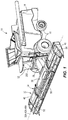
FIG. 1 is a perspective view of an agricultural machine including a folding head according to one embodiment of the disclosure. -
FIG. 2 is a front view of the agricultural machine ofFIG. 1 , illustrating the folding head in a deployed configuration and in a folded configuration. -
FIG. 3 is an exploded view of a motion control assembly of the folding head ofFIG. 1 . -
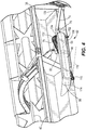
FIG. 4 is a perspective view of the motion control assembly ofFIG. 3 . -
FIG. 5A-5D illustrate movement of a wing of the folding head from a deployed position to a non-deployed or folded position. - Before any embodiments of the disclosure are explained in detail, it is to be understood that the disclosure is not limited in its application to the details of construction and the arrangement of components set forth in the following description or illustrated in the accompanying drawings. The disclosure is capable of supporting other embodiments and of being practiced or of being carried out in various ways.
-
FIG. 1 illustrates anagricultural machine 10, which is a combine harvester (or simply "combine") 10 in the illustrated embodiment. Thecombine 10 includes ahousing 14, a plurality of ground-engaging members (e.g., wheels) 18 supporting thehousing 14, and anoperator cab 22 disposed at a front end of thehousing 14. Thecombine 10 also includes afeederhouse 26 extending from the front end of thehousing 14 generally underneath theoperator cab 22 and ahead 30 coupled to thefeederhouse 26. Thehead 30 is configured to cut or pick up pre-cut crops and feed the crops into thefeederhouse 26, which then draws the crops into the housing 14 (e.g., via a rotating feeder drum). Within thehousing 14, harvested crops can be threshed to remove stalk material or straw via a separating system (not shown), leaving the crop grains that are to be collected. The crop grains may be further processed within the housing 14 (e.g., to remove chaff) and ultimately stored within and/or discharged from thehousing 14. The threshing and processing of the crops can be accomplished by any one of a variety of mechanisms. - With continued reference to
FIG. 1 , thehead 30 includes aframe 34 having a plurality of segments. In the illustrated embodiment, theframe 34 includes acenter segment 38 coupled to thefeederhouse 26, aleft wing 42 coupled to thecenter segment 38, and aright wing 46 coupled to thecenter segment 38 opposite theleft wing 42. Each of thesegments cutter bar 50 and aconveying mechanism 54 that can carry cut crops toward the center of thehead 30 for intake into thefeederhouse 26. Each of thesegments longitudinal axis cutter bar 50. - In the illustrated embodiment, the
head 30 is a draper head, and theconveying mechanism 54 of each segment includes a conveyor belt. In other embodiments, theconveying mechanisms 54 may include one or more rotatable augers, a combination of conveyor belts and augers, or any other means suitable for carrying crops toward thefeederhouse 26. The illustratedhead 30 also includes arotatable reel 58 provided on eachsegment head 30 is configured for harvesting grain. In other embodiments, thehead 30 may be any other type of agricultural head, such as a corn head, auger platform, belt pick up, and the like, and thesegments reels 58. - Referring to
FIG. 2 , theleft wing 42 and theright wing 46 are movable relative to thecenter segment 38 between a non-deployed or folded position (illustrated in solid lines inFIG. 2 ), defining a non-deployed or folded configuration of thehead 30, and deployed position (illustrated in phantom lines inFIG. 2 ), defining a deployed configuration of thehead 30. In some embodiments, thehead 30 has an overall width W1 in the deployed configuration (measured from an outermost point of theleft wing 42 to an outermost point of the right wing 46) between thirty-five feet and sixty feet. In other embodiments, thehead 30 has an overall width W1 in the deployed configuration between forty-five feet and sixty feet. In other embodiments, thehead 30 has an overall width W1 in the deployed configuration between fifty feet and sixty feet. - The
head 30 has a maximum width W2 in the folded configuration that is less than the overall width W1 of thehead 30 in the deployed configuration (FIG. 2 ). In some embodiments, the maximum width W2 may be defined by the outermost point on theleft wing 42 and the outermost point on theright wing 46. In other embodiments, the maximum width W2 may be defined by outermost points of thecenter segment 38. In some embodiments, thehead 30 has a maximum width W2 in the folded configuration between twenty feet and forty feet. In some embodiments, thehead 30 has a maximum width W2 in the folded configuration between twenty feet and thirty feet. In some embodiments, a ratio of the maximum width W2 in the folded configuration to the overall length W1 in the deployed position is between 0.5 and 0.8. - With reference to
FIGS. 3 and4 , each of thewings center segment 38 by amotion control assembly 62. Themotion control assembly 62 for theright wing 46 is substantially similar to themotion control assembly 62 for theleft wing 42; accordingly, only themotion control assembly 62 for theleft wing 42 is described in detail herein. - The illustrated
motion control assembly 62 includes afirst link 66, asecond link 70, and anactuator 74. Thefirst link 66 has afirst end 78 pivotally coupled to aboss 82 on thecenter segment 38 and a second,opposite end 86 pivotally coupled to aboss 90 on thewing 42. An integrally-formedcontrol tab 94 extends upward from thefirst link 66 between the first andsecond ends first link 66 defines alongitudinal axis 98 extending between the first andsecond ends second link 70 has afirst end 102 pivotally coupled to apost 106 on thecenter segment 38 and asecond end 110 pivotally coupled to apost 114 on thewing 42 that defines apin axis 118. In the illustrated embodiment, thesecond link 70 includes acurved portion 122 between its first andsecond ends second link 70 is generally hook-shaped. Thecurved portion 122 embraces or wraps around at least a portion of theboss 82 on thecenter segment 38 and thefirst end 78 of thefirst link 66 when thewing 42 is in the deployed position (FIGS. 4 and5A ). - When the
wing 42 is in the deployed position, thesecond link 70 crosses in front of thefirst link 66 such that thefirst link 66 overlies a portion of thesecond link 70 when viewed from the rear (FIG. 5A ). As such, thepivot axis 118 of thesecond link 70 is offset to one side of thelongitudinal axis 98 of thefirst link 66. When thewing 42 is in the folded position, however, thefirst link 66 does not overlie any portion of thesecond link 70 when viewed from the rear (FIG. 5D ). As such, thepivot axis 118 of thesecond link 70 is offset to an opposite side of thelongitudinal axis 98 of thefirst link 66. Thus, as thewing 42 moves from the deployed position (FIG. 5A ) to the folded position (FIG. 5D ), thepivot axis 118 of thesecond link 70 crosses thelongitudinal axis 98 of thefirst link 66. - Referring to
FIGS. 3 and4 , the illustratedactuator 74 is a hydraulic cylinder that includes acylinder body 130 and arod 134 displaceable relative to thecylinder body 130 in response to the introduction of pressurized hydraulic fluid into thecylinder body 130. Thehydraulic cylinder 74 may be single acting or double acting. Thecylinder body 130 is pivotally coupled to thecenter segment 38, and therod 134 is pivotally coupled to thecontrol tab 94 on thefirst link 66, at a position offset from thelongitudinal axis 98. Accordingly, displacement of therod 134 relative to thecylinder 130 drives thefirst link 66. Alternatively, thecylinder body 130 may be pivotally coupled to thecontrol tab 94, and therod 134 may be pivotally coupled to thecenter segment 38. In other embodiments, themotion control assembly 62 may include other types of actuators, such as pneumatic or electronic actuators. - Best illustrated in
FIG. 3 , thehead 30 further includes areleasable pivot assembly 138. Thereleasable pivot assembly 138 includes asaddle 142 disposed on thecenter segment 38 and aprojection 146 disposed on thewing 42 that is received within anopen recess 150 defined by thesaddle 142 to form a pivoting connection when thewing 42 is in the deployed position. As such, thewing 42 can pivot relative to thecenter segment 38 about thereleasable pivot assembly 138 when thewing 42 is in the deployed position. This is referred to as ground contouring. Thecutter bar 50 on thewing 42 is kept closer to the ground because thewing 42 can pivot to compensate for varied terrain. In other embodiments, thesaddle 142 may be located on thewing 42, and theprojection 146 may be located on thecenter segment 38. - With continued reference to
FIG. 3 , thereleasable pivot assembly 138 includes alatch mechanism 154 to selectively lock theprojection 146 into pivoting engagement with thesaddle 142 and inhibit removal of theprojection 146 from thesaddle recess 150. In the illustrated embodiment, thelatch mechanism 154 includes adisplaceable pin 158 that is movable between a latched position in which thepin 158 extends through theprojection 146 and thesaddle 142 and an unlatched position in which thepin 158 is at least partially withdrawn so as to permit theprojection 146 to be removed from thesaddle recess 150. When thepin 158 is in the latched position, thewing 42 is pivotable about thepin 158 relative to thecenter segment 38 to permit ground contouring. - The illustrated
latch mechanism 154 includes anactuator 162 to displace thepin 158 between the latched position and the unlatched position. Theactuator 162 can include any hydraulic, pneumatic, or electronic (e.g., solenoid) assembly suitable for displacing thepin 158. In some embodiments, additional releasable pivot assemblies (not shown) may be provided to selectively disengage one or both of the first andsecond links center segment 38 and thewing 42 when thelatch mechanism 154 is in the latched position. - In some embodiments, the
projection 146 may be a cylindrical member configured to pivot directly within therecess 150 of thesaddle 142. In such embodiments, thelatch mechanism 154 does not include thepin 158. Rather, thelatch mechanism 154 includes a gate that secures theprojection 146 within therecess 150 when in the latched position and permits theprojection 146 to be inserted into or removed from therecess 150 when in the unlatched position. - Best illustrated in
FIGS. 5B and5C , thecenter segment 38 includes afirst end surface 170 and thewing 42 includes asecond end surface 174. Thefirst end surface 170 is oriented so as to define a first oblique includedangle 178 between thefirst end surface 170 and thelongitudinal axis 38A of thecenter segment 38. Similarly, thesecond end surface 174 is oriented so as to define a second oblique includedangle 182 between thesecond end surface 174 and thelongitudinal axis 42A of thewing 42. In the illustrated embodiment, the first oblique includedangle 178 is equal in magnitude to the second oblique includedangle 182. In some embodiments, theangles angles angles angles second angles angle 182 may be greater than the first oblique includedangle 178 so that the end surfaces 170, 174 diverge. This provides clearance for thewing 42 to pivot relative to the center segment 38 (about the pivot assembly 138) for ground contouring. - When the
wing 42 is in the deployed position (FIG. 5A ), thefirst end surface 170 is positioned adjacent thesecond end surface 174 and faces thesecond end surface 174. As used in this context, the term "adjacent" means that thefirst end surface 170 has at least one point that is within six inches of at least one point on thesecond end surface 174. When thewing 42 is in the folded position (FIG. 5D ), thefirst end surface 170 is positioned remote from thesecond end surface 174 and faces away from thesecond end surface 174. As used in this context, the term "remote" means that thefirst end surface 170 has at least one point that is more than two feet away from every point on thesecond end surface 174. - With reference to
FIG. 1 , the illustratedcombine 10 includes acontroller 200, which may include a plurality of electrical and electronic components that provide power, operational control, and protection to the components and modules within thecontroller 200. For example, thecontroller 200 may include an electronic processor or central processing unit (e.g., a programmable microprocessor, microcontroller, or similar device), non-transitory, machine-readable memory, and an input/output interface. Software for controlling various aspects of the operation of thecombine 10 can be stored in the memory of thecontroller 200. The software includes, for example, firmware, one or more applications, program data, filters, rules, one or more program modules, and other executable instructions. Thecontroller 200 may be configured to retrieve from memory and execute, among other things, instructions related to the control processes and methods described herein. Thecontroller 200 may also include one or more mechanical or electro-mechanical components, such as steering, throttle, and braking controls. In other embodiments, thecontroller 200 may include additional, fewer, or different components. - The
controller 200 is in communication with theactuator 74 of eachmotion control assembly 62 and with theactuator 162 of eachlatch mechanism 154. Accordingly, thecontroller 200 is capable of sending signals or commands (in the form of wired or wireless communication, hydraulic pressure, pneumatic pressure, or in a combination of forms) to control actuation of themotion control assemblies 62 and thelatch mechanisms 154 in response to user commands, or, in some embodiments, automatically. - In operation, when the
head 30 is in the deployed configuration and thecombine 10 is operating on level ground, thelongitudinal axes center segment 38 and thewings FIG. 1 ). Theprojection 146 of thereleasable pivot assembly 138 is received within thesaddle 142, and thelatch mechanism 154 for eachwing FIGS. 3 and5A ). In some embodiments (e.g., where clearance is provided between the end surfaces 170, 174), one or both of thewings releasable pivot assembly 138 to provide ground contouring if thehead 30 encounters sloped terrain. - When an operator desires to place the
head 30 in the folded configuration (e.g., when transporting the combine 10), thecontroller 200 first actuates eachlatch mechanism 154 to move to the unlatched position, allowing theprojection 146 to be removed from thesaddle recess 150. Next, thecontroller 200 commands theactuator 74 of eachmotion control assembly 62 to move its associatedwing 42 to the folded position shown inFIG. 5D . Thelinks center segment 38, and thewing 42 function as a four-bar linkage such that thelongitudinal axis wing longitudinal axis 38A of the center segment as thewings FIGS. 5B and5C ). In addition, eachwing FIG. 5D ). The obliquely angled end surfaces 170, 174 at the interface between thecenter segment 38 and eachwing projection 146 to lift out of thesaddle recess 150 as eachwing wing wings wings - To return the
head 30 to the deployed configuration, thecontroller 200 commands theactuator 74 of eachmotion control assembly 62 to move its associatedwing wing continuous arc 204, and theprojection 146 on eachwing saddle recess 150 when thewing controller 200 may then actuate eachlatch mechanism 154 to the latched position. - Various features of the disclosure are set forth in the following claims.
Claims (20)
- A head for an agricultural machine, the head comprising:a frame including a center segment defining a first longitudinal axis and a wing defining a second longitudinal axis; anda motion control assembly connecting the center segment and the wing such that the wing is movable relative to the center segment between a deployed position and a non-deployed position,wherein the motion control assembly is configured to maintain the second longitudinal axis in a parallel relationship with the first longitudinal axis as the wing moves between the deployed position and the non-deployed position, andwherein the wing is movable from the deployed position to the non-deployed position along a continuous arc.
- The head of claim 1, wherein the center segment includes a first end surface, wherein the wing includes a second end surface, and wherein the first end surface is adjacent the second end surface in the deployed position of the wing.
- The head of claim 2, wherein the first end surface is remote from the second end surface in the non-deployed position of the wing.
- The head of claim 2, wherein the first end surface and the first longitudinal axis define a first oblique included angle, and wherein the second end surface and the second longitudinal axis define a second oblique included angle.
- The head of claim 4, wherein the first and second oblique included angles are equal such that the first end surface is parallel to the second end surface when the first longitudinal axis is parallel to the second longitudinal axis.
- The head of claim 1, wherein the motion control assembly includes a first link and a second link, each link having a first end pivotally coupled to the center segment and a second end pivotally coupled to the wing such that the center segment, the wing, and the first and second links define a four-bar linkage.
- The head of claim 1, further comprising a releasable pivot assembly configured to selectively pivotally couple the wing to the center segment.
- The head of claim 7, wherein in the releasable pivot assembly includes a projection located on one of the wing and the center segment, and a saddle located on the other of the wing and the center segment, wherein the saddle includes a recess configured to receive the projection when the wing is in the deployed position, and wherein the projection is not received in the recess when the wing is in the folded position.
- The head of claim 8, wherein the releasable pivot assembly includes a latch mechanism movable between a latched position and an unlatched position, and wherein the latch mechanism is configured to retain the projection within the recess when the latch mechanism is in the latched position.
- The head of claim 9, wherein the latch mechanism is configured to move to the unlatched position before the wing moves from the deployed position toward the non-deployed position.
- A combine comprising:a housing;a feederhouse coupled to a front end of the housing;a head coupled to the feederhouse, the head including a frame having a center segment that defines a first longitudinal axis and includes a first end surface, and a wing that defines a second longitudinal axis and includes a second end surface; anda motion control assembly connecting the center segment and the wing such that the wing is movable relative to the center segment between a deployed position and a non-deployed position,wherein the first end surface faces the second end surface when the wing is in the deployed position and faces away from the second end surface when the wing is in the non-deployed position,wherein the first end surface and the first longitudinal axis define a first oblique included angle, andwherein the second end surface and the second longitudinal axis define a second oblique included angle.
- The combine of claim 11, wherein the first and second oblique included angles are equal such that the first end surface is parallel to the second end surface when the first longitudinal axis is parallel to the second longitudinal axis.
- The combine of claim 11, wherein the motion control assembly includes a first link and a second link, each having a first end pivotally coupled to the center segment and a second end pivotally coupled to the wing such that the center segment, the wing, and the first and second links define a four-bar linkage.
- The combine of claim 13, wherein the first link defines a third longitudinal axis extending between the first end and the second end of the first link, wherein the second end of the second link is pivotal about a pin axis, and wherein the pin axis crosses the third longitudinal axis when the wing moves from the deployed position to the non-deployed position.
- The combine of claim 13, wherein the second link includes a curved portion.
- A head for an agricultural machine, the head comprising:a frame including a center segment and a wing; anda motion control assembly connecting the center segment and the wing such that the wing is movable relative to the center segment between a deployed position and a non-deployed position; anda releasable pivot assembly selectively pivotally coupling the wing and the center segment when the wing is in the deployed position, the releasable pivot assembly includinga projection located on one of the wing and the center segment, anda saddle located on the other of the wing and the center segment, the saddle having a recess configured to receive the projection when the wing is in the deployed position,wherein the projection is insertable into the recess and removable from the recess without linearly translating the wing relative to the center segment.
- The head of claim 16, further comprising a latch mechanism movable between a latched position and an unlatched position, wherein the latch mechanism is configured to retain the projection within the recess when the latch mechanism is in the latched position, and wherein the latch mechanism is configured to move to the unlatched position before the wing moves from the deployed position toward the non-deployed position.
- The head of claim 16, wherein the motion control assembly includes a first link and a second link, each having a first end pivotally coupled to the center segment and a second end pivotally coupled to the wing such that the center segment, the wing, and the first and second links define a four-bar linkage.
- The head of claim 18, wherein the motion control assembly includes a hydraulic actuator extending between the first link and the center segment, the hydraulic actuator operable to pivot the first link to move the wing between the deployed position and the non-deployed position.
- The head of claim 18, wherein the first link defines a longitudinal axis extending between the first end and the second end of the first link, wherein the second end of the second link is pivotal about a pin axis, and wherein the pin axis crosses the longitudinal axis when the wing moves from the deployed position to the non-deployed position.
Applications Claiming Priority (1)
| Application Number | Priority Date | Filing Date | Title |
|---|---|---|---|
| US15/729,867 US10537063B2 (en) | 2017-10-11 | 2017-10-11 | Folding agricultural head |
Publications (3)
| Publication Number | Publication Date |
|---|---|
| EP3469875A2 true EP3469875A2 (en) | 2019-04-17 |
| EP3469875A3 EP3469875A3 (en) | 2020-09-16 |
| EP3469875B1 EP3469875B1 (en) | 2023-03-22 |
Family
ID=63832183
Family Applications (1)
| Application Number | Title | Priority Date | Filing Date |
|---|---|---|---|
| EP18199265.2A Active EP3469875B1 (en) | 2017-10-11 | 2018-10-09 | Folding agricultural header |
Country Status (4)
| Country | Link |
|---|---|
| US (1) | US10537063B2 (en) |
| EP (1) | EP3469875B1 (en) |
| BR (1) | BR102018068315B1 (en) |
| CA (1) | CA3016940A1 (en) |
Cited By (1)
| Publication number | Priority date | Publication date | Assignee | Title |
|---|---|---|---|---|
| WO2025169138A1 (en) * | 2024-02-07 | 2025-08-14 | Hyler BV | Processing machine for processing fibre plants and use thereof |
Families Citing this family (3)
| Publication number | Priority date | Publication date | Assignee | Title |
|---|---|---|---|---|
| US10813289B2 (en) * | 2018-06-05 | 2020-10-27 | Deere & Company | Single top beam folding corn head mainframe |
| US11490568B2 (en) * | 2020-03-11 | 2022-11-08 | Deere & Company | Pivoting apparatus for row head |
| US11785890B2 (en) * | 2020-06-17 | 2023-10-17 | Deere & Company | Corn head adjustment system with integrated actuation |
Family Cites Families (61)
| Publication number | Priority date | Publication date | Assignee | Title |
|---|---|---|---|---|
| US2608041A (en) | 1947-01-24 | 1952-08-26 | Case Co J I | Conveying means for harvester headers |
| NL6414183A (en) * | 1964-12-05 | 1966-06-06 | ||
| NL6903371A (en) * | 1969-03-05 | 1970-09-08 | ||
| US4487004A (en) | 1983-06-03 | 1984-12-11 | Kejr Melvin P | Combine harvester apparatus |
| IT1256795B (en) * | 1992-01-31 | 1995-12-15 | Capello R & F Flli | FOLDABLE HEAD FOR THE CORN COLLECTION, PERFECTED. |
| CA2110775C (en) | 1993-12-06 | 1999-03-02 | Gregory J. Honey | A feeder adapter for mounting a combine header to a feeder housing of a combine |
| DE19523255A1 (en) | 1995-06-27 | 1997-01-02 | Claas Saulgau Gmbh | Header on agricultural machines for picking up and moving on straw crops, for example maize plants |
| US5577563A (en) * | 1995-07-27 | 1996-11-26 | Holen; Kurt | Stack-folding toolbar with floating wings |
| US5724798A (en) * | 1996-07-08 | 1998-03-10 | Byron Enterprises Inc. | Latch for a folding corn head |
| US5673543A (en) * | 1996-01-04 | 1997-10-07 | Byron Enterprises, Inc | Foldable corn head with unobstructed auger |
| US6003615A (en) | 1998-08-19 | 1999-12-21 | Moore; Paul O. | Stacking tool bar including a wing flex structure |
| US6202397B1 (en) | 1999-05-27 | 2001-03-20 | Deere & Company | Draper belt tensioning mechanism for a harvesting platform |
| DE10039097A1 (en) * | 2000-08-07 | 2002-02-21 | Claas Saulgau Gmbh | Method and device for pivoting the dividers of multi-part agricultural harvesters |
| CA2387898C (en) | 2001-06-18 | 2005-01-11 | Macdon Industries Ltd. | Multi-section header with flexible crop cutting knife |
| HUP0300512A2 (en) * | 2002-03-28 | 2004-09-28 | Claas Saulgau Gmbh | Reaper knife |
| DE10221983A1 (en) * | 2002-05-17 | 2003-11-27 | Kemper Gmbh Maschf | header |
| DE10250337A1 (en) * | 2002-10-29 | 2004-05-19 | Maschinenfabrik Kemper Gmbh & Co. Kg | Adjustment device for a header |
| US6865871B2 (en) | 2003-07-14 | 2005-03-15 | Macdon Industries Ltd. | Crop feed arrangement for the header of a combine harvester |
| US7168226B2 (en) | 2004-03-31 | 2007-01-30 | Cnh America Llc | Independent hydraulic header lift and flotation system |
| US7392646B2 (en) | 2004-06-16 | 2008-07-01 | Macdon Industries Ltd. | Reversible feed roller with radially extendible fingers |
| US7467668B2 (en) | 2005-03-31 | 2008-12-23 | Kimball Von D | Transport lock joint for stack fold toolbar |
| US20080276590A1 (en) | 2006-02-10 | 2008-11-13 | Agco Corporation | Flexible draper and cutter bar with tilt arm for cutterbar drive |
| US20070193243A1 (en) | 2006-02-10 | 2007-08-23 | Schmidt James R | Combine Harvester Draper Header Having Flexible Cutterbar |
| US7540130B2 (en) | 2006-03-02 | 2009-06-02 | Deere & Company | Height control for a multi-section cutting platform in an agricultural harvesting machine |
| US7918076B2 (en) | 2006-09-25 | 2011-04-05 | Macdon Industries Ltd. | Device for maintaining wing balance on a multi-section header |
| CA2572274C (en) | 2006-12-29 | 2014-05-27 | Honey Bee Manufacturing Ltd. | Rock trap for combine header |
| US7614206B2 (en) | 2007-06-04 | 2009-11-10 | Claas Selbstfahrende Erntemaschinen Gmbh | Winged header apparatus and method for a combine |
| US7587885B2 (en) | 2007-06-04 | 2009-09-15 | Claas Selbstfahrende Emtemaschinen Gmbh | Central auger crop feed system for a harvester |
| US7921627B2 (en) | 2008-05-09 | 2011-04-12 | Agco Corporation | Interlocking belt guards for a draper header |
| US7788891B2 (en) | 2008-06-27 | 2010-09-07 | Deere & Company | Endless belt mounting configuration for an agricultural harvester |
| US8281561B2 (en) | 2010-08-17 | 2012-10-09 | Deere & Company | Flexible draper belt drive for an agricultural harvesting machine |
| DE102010037131A1 (en) | 2010-08-24 | 2012-03-01 | Claas Selbstfahrende Erntemaschinen Gmbh | cutting |
| US7992372B1 (en) | 2010-09-16 | 2011-08-09 | Deere & Company | Draper platform with breakaway joint |
| US8087224B1 (en) | 2010-09-16 | 2012-01-03 | Deere & Company | Flexible draper platform with pivot geometry |
| US8336280B2 (en) | 2011-05-20 | 2012-12-25 | Deere & Company | Pivoting center conveyor for draper platform |
| US8544250B2 (en) | 2011-10-25 | 2013-10-01 | Deere & Company | Draper platform with center conveyor and method of replacing the center conveyor belt |
| ITPD20120242A1 (en) * | 2012-08-06 | 2014-02-07 | Cressoni S P A Flli | FOLDABLE HEAD FOR BRAIDING AND / OR HARVESTING MACHINE AND FILLING METHOD OF A BANNER MILLING AND / OR HARVESTING MACHINE |
| US8695315B2 (en) | 2012-08-09 | 2014-04-15 | Deere & Company | Draper header with pivoting side draper conveyors |
| US9198353B2 (en) | 2012-09-20 | 2015-12-01 | Deere & Company | Hinged row crop harvesting head |
| US9072222B2 (en) | 2012-09-20 | 2015-07-07 | Deere & Company | Self-centering cover for hinged row crop harvesting head |
| DE102013100322A1 (en) | 2013-01-14 | 2014-07-17 | Claas Selbstfahrende Erntemaschinen Gmbh | cutting |
| US8893088B2 (en) * | 2013-04-02 | 2014-11-18 | Apple Inc. | Dynamic program evaluation for system adaptation |
| US9198349B2 (en) | 2013-07-12 | 2015-12-01 | Deere & Company | Articulated harvesting head ground force control circuit |
| US9144199B2 (en) | 2013-08-30 | 2015-09-29 | Deere & Company | Articulated harvesting head load sensor arrangement |
| DE102014009161B4 (en) | 2014-06-25 | 2023-01-26 | Carl Geringhoff Gmbh & Co. Kg | Cutting unit with central part and adjustable side parts |
| DE102014216112A1 (en) | 2014-08-13 | 2016-02-18 | Walter Schmid | Self-propelled harvester |
| US9788486B2 (en) | 2014-12-30 | 2017-10-17 | Agco Corporation | Grain header with swathing and chopping capability |
| BR102016005189B1 (en) | 2015-03-13 | 2020-11-17 | Cnh Industrial Belgium Nv | AGRICULTURAL HARVESTER |
| US9668412B2 (en) | 2015-05-01 | 2017-06-06 | Deere & Company | Harvesting head height control circuit |
| US20160360699A1 (en) | 2015-06-10 | 2016-12-15 | Jose Luis Allochis | Conveyor belt tensing apparatus for a harvesting header |
| DE102015116892A1 (en) | 2015-10-05 | 2017-04-06 | Carl Geringhoff Gmbh & Co. Kg | Cutting unit with adjustable side frame relief |
| DE102015118143A1 (en) | 2015-10-23 | 2017-04-27 | Arnold Jäger Holding GmbH | Cam belts, especially for agricultural machines |
| BE1023925B1 (en) | 2016-03-01 | 2017-09-13 | Cnh Industrial Belgium Nv | FEEDING DEVICE FOR CUTTER |
| BE1024333B1 (en) | 2016-06-23 | 2018-02-01 | Cnh Industrial Belgium Nv | Cutting bar support for a harvesting machine |
| US10070575B2 (en) * | 2016-08-05 | 2018-09-11 | Cnh Industrial America Llc | Agricultural machine with folding header |
| US20180070526A1 (en) * | 2016-09-13 | 2018-03-15 | Cnh Industrial Canada, Ltd. | Apparatus and method to minimize transport dimensions of agricultural implements |
| DE102016118174A1 (en) | 2016-09-26 | 2018-03-29 | Claas Selbstfahrende Erntemaschinen Gmbh | cutting |
| US10375881B2 (en) | 2017-05-23 | 2019-08-13 | Cnh Industrial America Llc | Agricultural machine with sectional header |
| US10299437B2 (en) | 2017-07-17 | 2019-05-28 | Cnh Industrial America Llc | Header for an agricultural vehicle with deformable supports |
| US10820509B2 (en) * | 2017-08-08 | 2020-11-03 | Cnh Industrial America Llc | Foldable corn head |
| US10433483B2 (en) | 2017-08-21 | 2019-10-08 | Cnh Industrial America Llc | Agricultural header with one or more movable wing sections |
-
2017
- 2017-10-11 US US15/729,867 patent/US10537063B2/en active Active
-
2018
- 2018-09-07 CA CA3016940A patent/CA3016940A1/en active Pending
- 2018-09-11 BR BR102018068315-2A patent/BR102018068315B1/en active IP Right Grant
- 2018-10-09 EP EP18199265.2A patent/EP3469875B1/en active Active
Non-Patent Citations (1)
| Title |
|---|
| None |
Cited By (2)
| Publication number | Priority date | Publication date | Assignee | Title |
|---|---|---|---|---|
| WO2025169138A1 (en) * | 2024-02-07 | 2025-08-14 | Hyler BV | Processing machine for processing fibre plants and use thereof |
| BE1032393B1 (en) * | 2024-02-07 | 2025-09-08 | Hyler BV | PROCESSING MACHINE FOR PROCESSING FIBER PLANTS AND ITS USE |
Also Published As
| Publication number | Publication date |
|---|---|
| US20190104683A1 (en) | 2019-04-11 |
| EP3469875B1 (en) | 2023-03-22 |
| BR102018068315B1 (en) | 2023-11-28 |
| US10537063B2 (en) | 2020-01-21 |
| CA3016940A1 (en) | 2019-04-11 |
| EP3469875A3 (en) | 2020-09-16 |
| BR102018068315A2 (en) | 2019-05-07 |
Similar Documents
| Publication | Publication Date | Title |
|---|---|---|
| EP3469878B1 (en) | Roll center for harvester attachment frame control arms | |
| US9788486B2 (en) | Grain header with swathing and chopping capability | |
| AU2018201075B2 (en) | Combination flex and rigid header height control in a harvester | |
| EP2420128B1 (en) | Flexible draper belt drive for an agricultural harvesting machine | |
| US10426088B2 (en) | Center feed assembly for a draper | |
| US10257979B2 (en) | Harvester header pitch adjustment apparatus | |
| EP3469875B1 (en) | Folding agricultural header | |
| US20070204585A1 (en) | Lockout for float arms in a cutting platform of an agricultural harvesting machine | |
| EP3064052B1 (en) | Agricultural reel cam system | |
| EP3278653A1 (en) | Agricultural machine with folding header | |
| US12484481B2 (en) | Headland grain capture sequence for agricultural vehicle header | |
| US12495741B2 (en) | Harvesting machine belt pickup header with movable pickup belt assembly | |
| US20170318745A1 (en) | An agricultural harvester grain header auger | |
| US12245552B2 (en) | Adjustable reel arm | |
| EP2854502B1 (en) | Folding auger assembly for an agricultural harvester | |
| EP4033880B1 (en) | Feederhouse assemblies having biased lock pins, agricultural harvesters, and related methods | |
| JPH05192025A (en) | All culm input combine harvester rolling device | |
| BR112020004972B1 (en) | PLATFORM FOR AN AGRICULTURAL VEHICLE AND AGRICULTURAL VEHICLE | |
| JPH10327643A (en) | Combine grain stem raising device |
Legal Events
| Date | Code | Title | Description |
|---|---|---|---|
| PUAI | Public reference made under article 153(3) epc to a published international application that has entered the european phase |
Free format text: ORIGINAL CODE: 0009012 |
|
| STAA | Information on the status of an ep patent application or granted ep patent |
Free format text: STATUS: THE APPLICATION HAS BEEN PUBLISHED |
|
| AK | Designated contracting states |
Kind code of ref document: A2 Designated state(s): AL AT BE BG CH CY CZ DE DK EE ES FI FR GB GR HR HU IE IS IT LI LT LU LV MC MK MT NL NO PL PT RO RS SE SI SK SM TR |
|
| AX | Request for extension of the european patent |
Extension state: BA ME |
|
| RIC1 | Information provided on ipc code assigned before grant |
Ipc: A01B 73/04 20060101ALI20190513BHEP Ipc: A01D 41/14 20060101AFI20190513BHEP |
|
| PUAL | Search report despatched |
Free format text: ORIGINAL CODE: 0009013 |
|
| AK | Designated contracting states |
Kind code of ref document: A3 Designated state(s): AL AT BE BG CH CY CZ DE DK EE ES FI FR GB GR HR HU IE IS IT LI LT LU LV MC MK MT NL NO PL PT RO RS SE SI SK SM TR |
|
| AX | Request for extension of the european patent |
Extension state: BA ME |
|
| RIC1 | Information provided on ipc code assigned before grant |
Ipc: A01B 73/04 20060101ALI20200807BHEP Ipc: A01D 41/14 20060101AFI20200807BHEP |
|
| STAA | Information on the status of an ep patent application or granted ep patent |
Free format text: STATUS: REQUEST FOR EXAMINATION WAS MADE |
|
| 17P | Request for examination filed |
Effective date: 20210316 |
|
| RBV | Designated contracting states (corrected) |
Designated state(s): AL AT BE BG CH CY CZ DE DK EE ES FI FR GB GR HR HU IE IS IT LI LT LU LV MC MK MT NL NO PL PT RO RS SE SI SK SM TR |
|
| GRAP | Despatch of communication of intention to grant a patent |
Free format text: ORIGINAL CODE: EPIDOSNIGR1 |
|
| STAA | Information on the status of an ep patent application or granted ep patent |
Free format text: STATUS: GRANT OF PATENT IS INTENDED |
|
| INTG | Intention to grant announced |
Effective date: 20221027 |
|
| GRAS | Grant fee paid |
Free format text: ORIGINAL CODE: EPIDOSNIGR3 |
|
| GRAA | (expected) grant |
Free format text: ORIGINAL CODE: 0009210 |
|
| STAA | Information on the status of an ep patent application or granted ep patent |
Free format text: STATUS: THE PATENT HAS BEEN GRANTED |
|
| AK | Designated contracting states |
Kind code of ref document: B1 Designated state(s): AL AT BE BG CH CY CZ DE DK EE ES FI FR GB GR HR HU IE IS IT LI LT LU LV MC MK MT NL NO PL PT RO RS SE SI SK SM TR |
|
| REG | Reference to a national code |
Ref country code: GB Ref legal event code: FG4D |
|
| REG | Reference to a national code |
Ref country code: CH Ref legal event code: EP |
|
| REG | Reference to a national code |
Ref country code: DE Ref legal event code: R096 Ref document number: 602018047430 Country of ref document: DE |
|
| REG | Reference to a national code |
Ref country code: IE Ref legal event code: FG4D |
|
| REG | Reference to a national code |
Ref country code: AT Ref legal event code: REF Ref document number: 1554718 Country of ref document: AT Kind code of ref document: T Effective date: 20230415 |
|
| REG | Reference to a national code |
Ref country code: LT Ref legal event code: MG9D |
|
| REG | Reference to a national code |
Ref country code: NL Ref legal event code: MP Effective date: 20230322 |
|
| PG25 | Lapsed in a contracting state [announced via postgrant information from national office to epo] |
Ref country code: RS Free format text: LAPSE BECAUSE OF FAILURE TO SUBMIT A TRANSLATION OF THE DESCRIPTION OR TO PAY THE FEE WITHIN THE PRESCRIBED TIME-LIMIT Effective date: 20230322 Ref country code: NO Free format text: LAPSE BECAUSE OF FAILURE TO SUBMIT A TRANSLATION OF THE DESCRIPTION OR TO PAY THE FEE WITHIN THE PRESCRIBED TIME-LIMIT Effective date: 20230622 Ref country code: LV Free format text: LAPSE BECAUSE OF FAILURE TO SUBMIT A TRANSLATION OF THE DESCRIPTION OR TO PAY THE FEE WITHIN THE PRESCRIBED TIME-LIMIT Effective date: 20230322 Ref country code: LT Free format text: LAPSE BECAUSE OF FAILURE TO SUBMIT A TRANSLATION OF THE DESCRIPTION OR TO PAY THE FEE WITHIN THE PRESCRIBED TIME-LIMIT Effective date: 20230322 Ref country code: HR Free format text: LAPSE BECAUSE OF FAILURE TO SUBMIT A TRANSLATION OF THE DESCRIPTION OR TO PAY THE FEE WITHIN THE PRESCRIBED TIME-LIMIT Effective date: 20230322 |
|
| REG | Reference to a national code |
Ref country code: AT Ref legal event code: MK05 Ref document number: 1554718 Country of ref document: AT Kind code of ref document: T Effective date: 20230322 |
|
| PG25 | Lapsed in a contracting state [announced via postgrant information from national office to epo] |
Ref country code: SE Free format text: LAPSE BECAUSE OF FAILURE TO SUBMIT A TRANSLATION OF THE DESCRIPTION OR TO PAY THE FEE WITHIN THE PRESCRIBED TIME-LIMIT Effective date: 20230322 Ref country code: NL Free format text: LAPSE BECAUSE OF FAILURE TO SUBMIT A TRANSLATION OF THE DESCRIPTION OR TO PAY THE FEE WITHIN THE PRESCRIBED TIME-LIMIT Effective date: 20230322 Ref country code: GR Free format text: LAPSE BECAUSE OF FAILURE TO SUBMIT A TRANSLATION OF THE DESCRIPTION OR TO PAY THE FEE WITHIN THE PRESCRIBED TIME-LIMIT Effective date: 20230623 Ref country code: FI Free format text: LAPSE BECAUSE OF FAILURE TO SUBMIT A TRANSLATION OF THE DESCRIPTION OR TO PAY THE FEE WITHIN THE PRESCRIBED TIME-LIMIT Effective date: 20230322 |
|
| PG25 | Lapsed in a contracting state [announced via postgrant information from national office to epo] |
Ref country code: SM Free format text: LAPSE BECAUSE OF FAILURE TO SUBMIT A TRANSLATION OF THE DESCRIPTION OR TO PAY THE FEE WITHIN THE PRESCRIBED TIME-LIMIT Effective date: 20230322 Ref country code: RO Free format text: LAPSE BECAUSE OF FAILURE TO SUBMIT A TRANSLATION OF THE DESCRIPTION OR TO PAY THE FEE WITHIN THE PRESCRIBED TIME-LIMIT Effective date: 20230322 Ref country code: PT Free format text: LAPSE BECAUSE OF FAILURE TO SUBMIT A TRANSLATION OF THE DESCRIPTION OR TO PAY THE FEE WITHIN THE PRESCRIBED TIME-LIMIT Effective date: 20230724 Ref country code: ES Free format text: LAPSE BECAUSE OF FAILURE TO SUBMIT A TRANSLATION OF THE DESCRIPTION OR TO PAY THE FEE WITHIN THE PRESCRIBED TIME-LIMIT Effective date: 20230322 Ref country code: EE Free format text: LAPSE BECAUSE OF FAILURE TO SUBMIT A TRANSLATION OF THE DESCRIPTION OR TO PAY THE FEE WITHIN THE PRESCRIBED TIME-LIMIT Effective date: 20230322 Ref country code: AT Free format text: LAPSE BECAUSE OF FAILURE TO SUBMIT A TRANSLATION OF THE DESCRIPTION OR TO PAY THE FEE WITHIN THE PRESCRIBED TIME-LIMIT Effective date: 20230322 |
|
| PG25 | Lapsed in a contracting state [announced via postgrant information from national office to epo] |
Ref country code: SK Free format text: LAPSE BECAUSE OF FAILURE TO SUBMIT A TRANSLATION OF THE DESCRIPTION OR TO PAY THE FEE WITHIN THE PRESCRIBED TIME-LIMIT Effective date: 20230322 Ref country code: PL Free format text: LAPSE BECAUSE OF FAILURE TO SUBMIT A TRANSLATION OF THE DESCRIPTION OR TO PAY THE FEE WITHIN THE PRESCRIBED TIME-LIMIT Effective date: 20230322 Ref country code: IS Free format text: LAPSE BECAUSE OF FAILURE TO SUBMIT A TRANSLATION OF THE DESCRIPTION OR TO PAY THE FEE WITHIN THE PRESCRIBED TIME-LIMIT Effective date: 20230722 |
|
| REG | Reference to a national code |
Ref country code: DE Ref legal event code: R097 Ref document number: 602018047430 Country of ref document: DE |
|
| PLBE | No opposition filed within time limit |
Free format text: ORIGINAL CODE: 0009261 |
|
| STAA | Information on the status of an ep patent application or granted ep patent |
Free format text: STATUS: NO OPPOSITION FILED WITHIN TIME LIMIT |
|
| PG25 | Lapsed in a contracting state [announced via postgrant information from national office to epo] |
Ref country code: SI Free format text: LAPSE BECAUSE OF FAILURE TO SUBMIT A TRANSLATION OF THE DESCRIPTION OR TO PAY THE FEE WITHIN THE PRESCRIBED TIME-LIMIT Effective date: 20230322 Ref country code: DK Free format text: LAPSE BECAUSE OF FAILURE TO SUBMIT A TRANSLATION OF THE DESCRIPTION OR TO PAY THE FEE WITHIN THE PRESCRIBED TIME-LIMIT Effective date: 20230322 Ref country code: CZ Free format text: LAPSE BECAUSE OF FAILURE TO SUBMIT A TRANSLATION OF THE DESCRIPTION OR TO PAY THE FEE WITHIN THE PRESCRIBED TIME-LIMIT Effective date: 20230322 |
|
| 26N | No opposition filed |
Effective date: 20240102 |
|
| PG25 | Lapsed in a contracting state [announced via postgrant information from national office to epo] |
Ref country code: IT Free format text: LAPSE BECAUSE OF FAILURE TO SUBMIT A TRANSLATION OF THE DESCRIPTION OR TO PAY THE FEE WITHIN THE PRESCRIBED TIME-LIMIT Effective date: 20230322 Ref country code: MC Free format text: LAPSE BECAUSE OF FAILURE TO SUBMIT A TRANSLATION OF THE DESCRIPTION OR TO PAY THE FEE WITHIN THE PRESCRIBED TIME-LIMIT Effective date: 20230322 |
|
| REG | Reference to a national code |
Ref country code: CH Ref legal event code: PL |
|
| REG | Reference to a national code |
Ref country code: BE Ref legal event code: MM Effective date: 20231031 |
|
| PG25 | Lapsed in a contracting state [announced via postgrant information from national office to epo] |
Ref country code: LU Free format text: LAPSE BECAUSE OF NON-PAYMENT OF DUE FEES Effective date: 20231009 |
|
| GBPC | Gb: european patent ceased through non-payment of renewal fee |
Effective date: 20231009 |
|
| PG25 | Lapsed in a contracting state [announced via postgrant information from national office to epo] |
Ref country code: LU Free format text: LAPSE BECAUSE OF NON-PAYMENT OF DUE FEES Effective date: 20231009 |
|
| PG25 | Lapsed in a contracting state [announced via postgrant information from national office to epo] |
Ref country code: GB Free format text: LAPSE BECAUSE OF NON-PAYMENT OF DUE FEES Effective date: 20231009 |
|
| PG25 | Lapsed in a contracting state [announced via postgrant information from national office to epo] |
Ref country code: CH Free format text: LAPSE BECAUSE OF NON-PAYMENT OF DUE FEES Effective date: 20231031 |
|
| PG25 | Lapsed in a contracting state [announced via postgrant information from national office to epo] |
Ref country code: GB Free format text: LAPSE BECAUSE OF NON-PAYMENT OF DUE FEES Effective date: 20231009 Ref country code: FR Free format text: LAPSE BECAUSE OF NON-PAYMENT OF DUE FEES Effective date: 20231031 Ref country code: CH Free format text: LAPSE BECAUSE OF NON-PAYMENT OF DUE FEES Effective date: 20231031 |
|
| PG25 | Lapsed in a contracting state [announced via postgrant information from national office to epo] |
Ref country code: BE Free format text: LAPSE BECAUSE OF NON-PAYMENT OF DUE FEES Effective date: 20231031 |
|
| PG25 | Lapsed in a contracting state [announced via postgrant information from national office to epo] |
Ref country code: IE Free format text: LAPSE BECAUSE OF NON-PAYMENT OF DUE FEES Effective date: 20231009 |
|
| PG25 | Lapsed in a contracting state [announced via postgrant information from national office to epo] |
Ref country code: IE Free format text: LAPSE BECAUSE OF NON-PAYMENT OF DUE FEES Effective date: 20231009 |
|
| PG25 | Lapsed in a contracting state [announced via postgrant information from national office to epo] |
Ref country code: BG Free format text: LAPSE BECAUSE OF FAILURE TO SUBMIT A TRANSLATION OF THE DESCRIPTION OR TO PAY THE FEE WITHIN THE PRESCRIBED TIME-LIMIT Effective date: 20230322 |
|
| PG25 | Lapsed in a contracting state [announced via postgrant information from national office to epo] |
Ref country code: BG Free format text: LAPSE BECAUSE OF FAILURE TO SUBMIT A TRANSLATION OF THE DESCRIPTION OR TO PAY THE FEE WITHIN THE PRESCRIBED TIME-LIMIT Effective date: 20230322 |
|
| PG25 | Lapsed in a contracting state [announced via postgrant information from national office to epo] |
Ref country code: CY Free format text: LAPSE BECAUSE OF FAILURE TO SUBMIT A TRANSLATION OF THE DESCRIPTION OR TO PAY THE FEE WITHIN THE PRESCRIBED TIME-LIMIT; INVALID AB INITIO Effective date: 20181009 |
|
| PG25 | Lapsed in a contracting state [announced via postgrant information from national office to epo] |
Ref country code: HU Free format text: LAPSE BECAUSE OF FAILURE TO SUBMIT A TRANSLATION OF THE DESCRIPTION OR TO PAY THE FEE WITHIN THE PRESCRIBED TIME-LIMIT; INVALID AB INITIO Effective date: 20181009 |
|
| PG25 | Lapsed in a contracting state [announced via postgrant information from national office to epo] |
Ref country code: TR Free format text: LAPSE BECAUSE OF FAILURE TO SUBMIT A TRANSLATION OF THE DESCRIPTION OR TO PAY THE FEE WITHIN THE PRESCRIBED TIME-LIMIT Effective date: 20230322 |
|
| PGFP | Annual fee paid to national office [announced via postgrant information from national office to epo] |
Ref country code: DE Payment date: 20250919 Year of fee payment: 8 |