EP3469202B1 - Air turbine starter with decoupler - Google Patents
Air turbine starter with decoupler Download PDFInfo
- Publication number
- EP3469202B1 EP3469202B1 EP17731999.3A EP17731999A EP3469202B1 EP 3469202 B1 EP3469202 B1 EP 3469202B1 EP 17731999 A EP17731999 A EP 17731999A EP 3469202 B1 EP3469202 B1 EP 3469202B1
- Authority
- EP
- European Patent Office
- Prior art keywords
- output shaft
- drive shaft
- threaded portion
- shaft
- starter
- Prior art date
- Legal status (The legal status is an assumption and is not a legal conclusion. Google has not performed a legal analysis and makes no representation as to the accuracy of the status listed.)
- Active
Links
Images




Classifications
-
- F—MECHANICAL ENGINEERING; LIGHTING; HEATING; WEAPONS; BLASTING
- F02—COMBUSTION ENGINES; HOT-GAS OR COMBUSTION-PRODUCT ENGINE PLANTS
- F02C—GAS-TURBINE PLANTS; AIR INTAKES FOR JET-PROPULSION PLANTS; CONTROLLING FUEL SUPPLY IN AIR-BREATHING JET-PROPULSION PLANTS
- F02C7/00—Features, components parts, details or accessories, not provided for in, or of interest apart form groups F02C1/00 - F02C6/00; Air intakes for jet-propulsion plants
- F02C7/26—Starting; Ignition
- F02C7/268—Starting drives for the rotor, acting directly on the rotor of the gas turbine to be started
- F02C7/275—Mechanical drives
- F02C7/277—Mechanical drives the starter being a separate turbine
-
- F—MECHANICAL ENGINEERING; LIGHTING; HEATING; WEAPONS; BLASTING
- F02—COMBUSTION ENGINES; HOT-GAS OR COMBUSTION-PRODUCT ENGINE PLANTS
- F02C—GAS-TURBINE PLANTS; AIR INTAKES FOR JET-PROPULSION PLANTS; CONTROLLING FUEL SUPPLY IN AIR-BREATHING JET-PROPULSION PLANTS
- F02C7/00—Features, components parts, details or accessories, not provided for in, or of interest apart form groups F02C1/00 - F02C6/00; Air intakes for jet-propulsion plants
- F02C7/26—Starting; Ignition
- F02C7/268—Starting drives for the rotor, acting directly on the rotor of the gas turbine to be started
-
- F—MECHANICAL ENGINEERING; LIGHTING; HEATING; WEAPONS; BLASTING
- F02—COMBUSTION ENGINES; HOT-GAS OR COMBUSTION-PRODUCT ENGINE PLANTS
- F02C—GAS-TURBINE PLANTS; AIR INTAKES FOR JET-PROPULSION PLANTS; CONTROLLING FUEL SUPPLY IN AIR-BREATHING JET-PROPULSION PLANTS
- F02C7/00—Features, components parts, details or accessories, not provided for in, or of interest apart form groups F02C1/00 - F02C6/00; Air intakes for jet-propulsion plants
- F02C7/26—Starting; Ignition
- F02C7/268—Starting drives for the rotor, acting directly on the rotor of the gas turbine to be started
- F02C7/275—Mechanical drives
-
- F—MECHANICAL ENGINEERING; LIGHTING; HEATING; WEAPONS; BLASTING
- F02—COMBUSTION ENGINES; HOT-GAS OR COMBUSTION-PRODUCT ENGINE PLANTS
- F02C—GAS-TURBINE PLANTS; AIR INTAKES FOR JET-PROPULSION PLANTS; CONTROLLING FUEL SUPPLY IN AIR-BREATHING JET-PROPULSION PLANTS
- F02C7/00—Features, components parts, details or accessories, not provided for in, or of interest apart form groups F02C1/00 - F02C6/00; Air intakes for jet-propulsion plants
- F02C7/32—Arrangement, mounting, or driving, of auxiliaries
-
- F—MECHANICAL ENGINEERING; LIGHTING; HEATING; WEAPONS; BLASTING
- F02—COMBUSTION ENGINES; HOT-GAS OR COMBUSTION-PRODUCT ENGINE PLANTS
- F02C—GAS-TURBINE PLANTS; AIR INTAKES FOR JET-PROPULSION PLANTS; CONTROLLING FUEL SUPPLY IN AIR-BREATHING JET-PROPULSION PLANTS
- F02C7/00—Features, components parts, details or accessories, not provided for in, or of interest apart form groups F02C1/00 - F02C6/00; Air intakes for jet-propulsion plants
- F02C7/36—Power transmission arrangements between the different shafts of the gas turbine plant, or between the gas-turbine plant and the power user
-
- F—MECHANICAL ENGINEERING; LIGHTING; HEATING; WEAPONS; BLASTING
- F16—ENGINEERING ELEMENTS AND UNITS; GENERAL MEASURES FOR PRODUCING AND MAINTAINING EFFECTIVE FUNCTIONING OF MACHINES OR INSTALLATIONS; THERMAL INSULATION IN GENERAL
- F16D—COUPLINGS FOR TRANSMITTING ROTATION; CLUTCHES; BRAKES
- F16D9/00—Couplings with safety member for disconnecting, e.g. breaking or melting member
- F16D9/06—Couplings with safety member for disconnecting, e.g. breaking or melting member by breaking due to shear stress
- F16D9/08—Couplings with safety member for disconnecting, e.g. breaking or melting member by breaking due to shear stress over a single area encircling the axis of rotation, e.g. shear necks on shafts
-
- F—MECHANICAL ENGINEERING; LIGHTING; HEATING; WEAPONS; BLASTING
- F05—INDEXING SCHEMES RELATING TO ENGINES OR PUMPS IN VARIOUS SUBCLASSES OF CLASSES F01-F04
- F05D—INDEXING SCHEME FOR ASPECTS RELATING TO NON-POSITIVE-DISPLACEMENT MACHINES OR ENGINES, GAS-TURBINES OR JET-PROPULSION PLANTS
- F05D2220/00—Application
- F05D2220/30—Application in turbines
- F05D2220/32—Application in turbines in gas turbines
-
- F—MECHANICAL ENGINEERING; LIGHTING; HEATING; WEAPONS; BLASTING
- F05—INDEXING SCHEMES RELATING TO ENGINES OR PUMPS IN VARIOUS SUBCLASSES OF CLASSES F01-F04
- F05D—INDEXING SCHEME FOR ASPECTS RELATING TO NON-POSITIVE-DISPLACEMENT MACHINES OR ENGINES, GAS-TURBINES OR JET-PROPULSION PLANTS
- F05D2260/00—Function
- F05D2260/85—Starting
Definitions
- a driving mechanism such as a motor or engine, can generate driving motions at a mechanism output, such as at a rotatable output shaft.
- the output shaft can, for example, provide a rotational kinetic motion to another piece of equipment via a rotatable drive shaft connected to the output shaft.
- the piece of equipment receiving the rotational kinetic motion can utilize the driving rotational motion as an energy source to operate.
- a gas turbine engine also known as a combustion turbine engine, is a rotary engine that extracts energy from a flow of combusted gases passing through the engine onto a multitude of turbine blades.
- the gas turbine engine can provide at least a portion of the rotational kinetic motion to rotating equipment, such as an accessory gearbox, where the rotational motion is utilized to power a number of different accessories.
- the accessories can include generators, starter/generators, permanent magnet alternators (PMA) or permanent magnet generators (PMG), fuel pumps, and hydraulic pumps.
- PMA permanent magnet alternators
- PMG permanent magnet generators
- fuel pumps and hydraulic pumps.
- it can be desirable to decouple the driving mechanism from the rotating equipment.
- US 2,964,931 discloses a motion transmitting safety-type coupling for use between driving and driven members of a turbine.
- FR 2887945 discloses a shaft coupling that detaches when subjected to a reverse torque.
- the present disclosure relates to an air turbine starter according to claim 1.
- the present disclosure relates to a method for operating an air turbine starter, according to claim 10.
- the present invention is related to a driving mechanism generating kinetic motion in the form of a rotating shaft coupled with a piece of rotating equipment.
- a driving mechanism can include a gas turbine engine rotationally driving a piece of rotating equipment, such as a starter.
- the starter has various applications including starting a gas turbine engine and generating electrical power when the gas turbine engine is in operation. While the exemplary embodiment described herein is directed to application of a gas turbine engine and a starter, embodiments of the disclosure can be applied to any implementation of a driving mechanism that generates rotational motion at a driving output, and provides the rotational motion to another piece of rotating equipment.
- This assembly is commonly referred to as an Integrated Starter/Generator Gearbox (ISGB), or simply an air turbine starter 102.
- the gas turbine engine 1 comprises an air intake with a fan 50 that supplies air to a high pressure compression region 60.
- the air intake with a fan 50 and the high pressure compression region collectively are known as the 'cold section' of the gas turbine engine upstream of the combustion.
- the high pressure compression region 60 provides the combustion chamber 10 with high pressure air. In the combustion chamber, the high pressure air is mixed with fuel and combusted.
- the hot and pressurized combusted gas passes through a high pressure turbine region 20 and a low pressure turbine region 30 before exhausting from the gas turbine engine.
- the pressurized gases pass through the high pressure turbine (not shown) of the high pressure turbine region 20 and the low pressure turbine (not shown) of the low pressure turbine region 30, the turbines extract rotational energy from the flow of the gases passing through the gas turbine engine 1.
- the high pressure turbine of the high pressure turbine region 20 can be coupled to the compression mechanism (not shown) of the high pressure compression region 60 by way of a shaft to power the compression mechanism.
- the low pressure turbine can be coupled to the fan 50 of the air intake by way of a shaft to power the fan 50.
- the gas turbine engine can be a turbofan engine, such as a General Electric GEnx or CF6 series engine, commonly used in modern commercial and military aviation or it could be a variety of other known gas turbine engines such as a turboprop or turboshaft.
- the gas turbine engine can also have an afterburner that burns an additional amount of fuel downstream of the low pressure turbine region 30 to increase the velocity of the exhausted gases, and thereby increasing thrust.
- the AGB 100 is coupled to a turbine shaft of the gas turbine engine 1, either to the low pressure or high pressure turbine by way of a mechanical power take-off 90.
- the mechanical power take off 90 contains multiple gears and means for mechanical coupling of the AGB 100 to the gas turbine engine 1.
- the assembly 102 can be mounted on the outside of either the air intake region containing the fan 50 or on the core near the high pressure compression region 60.
- the air turbine starter 102 includes a housing 108 defining an inlet 110, an outlet 112, and a flow path 114 extending between the inlet 110 and outlet 112 for communicating a flow of gas there through.
- the air turbine starter 102 includes a turbine member 116 journaled within the housing 108 and disposed within the flow path 114 for rotatably extracting mechanical power from the flow of gas along the flow path 114.
- a gear train 118 disposed within the gear box 101 and drivingly coupled with the turbine member 116, can be caused to rotate.
- the gear train 118 includes a ring gear 120 and can further comprise any gear assembly including for example but not limited to a planetary gear assembly or a pinion gear assembly.
- a turbine shaft 122 couples the gear train 118 to the turbine member 116 allowing for the transfer of mechanical power.
- the turbine shaft 122 is rotatably mounted to the gear train 118 and supported by a pair of turbine bearings 124 while the gear train 118 is supported by a pair of carrier bearings 126.
- a gear box interior 127 can contain oil to provide lubrication and cooling to mechanical parts contained therein such as the gear train 118, ring gear 120, and bearings 124, 126.
- a drive shaft 136 extends from a portion of the gear box 101 and is coupled to the clutch 132 and additionally supported by the pair of spaced bearings 134.
- the drive shaft 136 is driven by the gear train 118 and coupled to the power take-off 90 of the gas turbine engine 1, such that operation of the engine 1 provides a driving motion to the gear box 101.
- the clutch 132 can be any type of shaft interface portion that forms a single rotatable shaft 138 including the turbine shaft 122, the carrier shaft 130, and the drive shaft 136.
- the shaft interface portion can be by any known method of coupling including, but not limited to, gears, splines, a clutch mechanism, or combinations thereof.
- An example of a shaft interface portion 132 is disclosed in United States Patent No. 4,281,942 to General Electric .
- the gear box 101 and the starter 102 can be formed by any known materials and methods, including, but not limited to, die-casting of high strength and lightweight metals such as aluminum, stainless steel, iron, or titanium.
- the housing for the gear box 101 and starter 102 can be formed with a thickness sufficient to provide adequate mechanical rigidity without adding unnecessary weight to the assembly 102 and, therefore, the aircraft.
- the rotatable shaft 138 can be constructed by any known materials and methods, including, but not limited to extrusion or machining of high strength metal alloys such as those containing aluminum, iron, nickel, chromium, titanium, tungsten, vanadium, or molybdenum.
- the diameter of the turbine shaft 122, carrier shaft 130, and drive shaft 136 can be fixed or vary along the length of the rotatable shaft 138. The diameter can vary to accommodate different sizes, as well as rotor to stator spacing.
- either the gear box 101 or the starter 102 can be a driving mechanism for driving the rotation of the rotating shafts 122, 130, 136.
- the starter 102 can be the driving mechanism for rotation of the rotating shafts 122, 130, 136.
- the gear box 101 can be the driving mechanism for rotation of the rotating shafts 122, 130, 136.
- the non-driving mechanism that is, the equipment being driven by the driving mechanism, can be understood as rotating equipment utilizing the rotational movement of the rotating shafts 122, 130, 136, for example to generate electricity in the starter 102.
- the drive shaft 136 is further coupled to a decoupler assembly 190 including a backdrive decoupler 200 having an output shaft 202, configured to be operably coupled to and rotate with the engine 1, and a tensile fuse 204.
- the tensile fuse 204 is selectively receivable and axially moveable within an internal threaded portion 206, that can be for example a helical female thread, of the output shaft 202. All joining parts can be formed from steel or like materials.
- FIG. 3 illustrates an exploded perspective view of one exemplary embodiment of the decoupler assembly 190 including the backdrive decoupler 200 and the drive shaft 136.
- the drive shaft 136 can include a circular depression 210 and an orthogonal depressions 212.
- the circular depression 210 is surrounded by the orthogonal depression 212.
- a central opening 214 is bound by a circular lip 216. Circumscribing the circular lip 216 are a plurality of stops 218.
- a thread insert 208 is included in the decoupler assembly 190 and is illustrated as including a complementary circular protrusion 220 and orthogonal portion 222 formed to fit into the circular and orthogonal shaped depressions 210, 212 of the drive shaft 136.
- the thread insert 208 further includes an internal helical threaded portion 224 which can be for example but not limited to a three helical female thread.
- the decoupler assembly 190 can also include a compression spring 217 and a ring spring 228.
- the output shaft 202 includes a first end 230 having an exteriorly threaded portion 234.
- the exteriorly threaded portion 234 can include, but is not limited to, a helical male thread, with a proximal end including complementary stops 236.
- a second end 232 is configured to be operably coupled to and rotate with the engine 1.
- the tensile fuse 204 includes a cylindrical first end 238.
- a second end 240 of the tensile fuse 204 includes a head 242 and a threaded portion 244 that can be, for example, a helical male thread, disposed beneath the head 242.
- the tensile fuse 204 further includes a neck portion 246 having a reduced diameter between the first end 238 and the threaded portion 244.
- the cylindrical first end 238 is received in the central opening 214 where a retainer pin 239 retains the first end 238 of the tensile fuse 204 within the drive shaft 136 operably coupling the tensile fuse 204 to the drive shaft 136.
- the tensile fuse 204 can be drilled and pinned with the retainer pin 239.
- the threaded portion 244 disposed beneath the head 242 is received within the internal threaded portion 206 of the output shaft 202
- the exteriorly threaded portion 234 of the output shaft 202 and the internal threaded portion 206 of the tensile fuse 204 are formed so that the tensile fuse 204 is threaded into the output shaft 202 with an opposite hand turn compared to when the output shaft 202 is threaded into the thread insert 208.
- the stops 218 and complementary stops 236 decrease axial loads along the threaded portions, 206, 224, 234, 244 when the output shaft 202 is fully threaded into the thread insert 208 of the drive shaft 136.
- FIG. 4A illustrates the decoupler assembly 190 mounted with the drive shaft 136. Because the drive shaft 136 and the thread insert 208 have corresponding circular depression 210, orthogonal depressions 212 and circular protrusion 220 and orthogonal portions 222, respectively, they can be operably coupled. Likewise, the complementary shapes of the stop 218 and 236 operably couple the drive shaft 136 to the output shaft 202. It should be understood that the shapes of the depressions and corresponding receiving portions depicted as orthogonal and circular and the shapes of the complementary stops are for illustrative purposes and not meant to be limiting.
- a biasing mechanism can be included between the thread insert 208 and the drive shaft 136.
- the biasing mechanism is the compression spring 217.
- a load path can go through mating stop features including the stops 218, 236 and transmit a driving torque. Under normal operating conditions the driving torque is transmitted from the drive shaft 136 of the clutch 132 to the output shaft 202 to drive the engine 1 by the mating stop features 218, 236.
- the load path leaves the threaded portions, 206, 224, 234, 244, the tensile fuse 204, and the retainer pin 239 unloaded.
- FIG. 4B A top view of the thread insert 208 in FIG. 4B illustrates the ring spring 228. Under normal operating conditions the threads of the exteriorly threaded portion 234 push the ring spring 228 outward into an inner portion 226 of the thread insert 208 in an expanded position.
- the air turbine starter 102 decouples its load path so that components of the gear box 101 and starter 102 are disconnected from the engine 1.
- the failing clutch 132 becomes engaged or locked while the engine 1 transmits an overrunning torque, with a magnitude of torque at or above the certain level, to the air turbine starter 102. This can also be considered a back driving torque.
- the backdrive decoupler 200 would be exposed to enough drag torque that the output shaft 202 would unwind from the drive shaft 136, and to simultaneously unwind the tensile fuse 204 from the output shaft 202.
- the thread ratios between the internal threaded portion 206 and the threaded portion 244 for the tensile fuse 204 compared to those between the internal threaded portion 224 and the threaded portion 234 for the output shaft 202 allow for the tensile fuse 204 to translate two times the translation distance of the output shaft 202, contributing to a high strain on the neck portion 246, causing it to shear and creating a sheared portion 250 and a base 252.
- the sheared portion 250 of the tensile fuse 204 is unwound from the output shaft 202 leaving the base 252 retained by the retainer pin 239.
- the unwinding of the output shaft 202 is further aided by the compressive spring 217.
- the compressive spring 217 is configured to expand and bias the output shaft 202 away from the drive shaft 136. It will be understood that any suitable biasing mechanism can be utilized and that the compressive spring is one illustrated example.
- a top view of the thread insert 208 in FIG. 5B illustrates the movement of the ring spring 228 in the event of a back drive. Because the output shaft 202 has translated, the threads of the exteriorly threaded portion 234 are no longer pushing the ring spring 228 outward. This allows the ring spring 228 to compress to a retracted position where the ring spring 228 overlies a portion of the thread insert 208 preventing rethreading of the first end 230 of the output shaft 202 and the thread insert 208. In this manner, the ring spring 228 is configured to secure the output shaft 202 in a decoupled and separate position from the drive shaft 136.
- a method 400 for operating an air turbine starter 102 is outlined in a flow chart in FIG. 6 .
- the method 400 begins at 402 with extracting mechanical power from a flow of gas utilizing a turbine 116 and driving the gear train 118 and clutch 132, including the drive shaft 136.
- a driving torque is transmitted from the drive shaft 136 to an output shaft 202 which is operably coupled to the engine 1.
- the backdrive decoupler 200 is activated when the tensile fuse 204 that is operably coupled to both the output shaft 202 and the drive shaft 136 is sheared.
- the sheared portion 250 of the tensile fuse 204 is then unwound from the output shaft 202 and translated away from the drive shaft 136.
- the output shaft 202 is unwound from the drive shaft 136 and translated away from the drive shaft 136.
- the output shaft 202 is prevented from reengaging the drive shaft 136 when the ring spring 228 contracts.
- the contraction of the ring spring 228 prevents the output shaft 202 from reengaging by blocking the internal helical threaded portion 224 from receiving the exteriorly threaded portion 234.
- the compression spring 217 is a secondary mechanism that also prevents reengagement when it has sprung. The springing of the compression spring 217 biases the output shaft202 out and away from the drive shaft 136.
- the air turbine starter 102 is therefore disabled after decoupling, which prevents an additional engine start.
- the aspects of the present disclosure provide a decoupler for decoupling a torque load coming from the gear train of an engine to prevent backdriving of the entire air turbine starter.
- Benefits associated with this decoupling include reducing the risk of spinning a damaged air turbine starter which could cause additional damage to the air turbine starter if not decoupled. Further still, the decoupling results in only the tensile fuse being needed to be replaced instead of more costly parts damaged by the continued backdriving.
Landscapes
- Engineering & Computer Science (AREA)
- Chemical & Material Sciences (AREA)
- Combustion & Propulsion (AREA)
- General Engineering & Computer Science (AREA)
- Mechanical Engineering (AREA)
- Control Of Turbines (AREA)
Description
- A driving mechanism, such as a motor or engine, can generate driving motions at a mechanism output, such as at a rotatable output shaft. The output shaft can, for example, provide a rotational kinetic motion to another piece of equipment via a rotatable drive shaft connected to the output shaft. The piece of equipment receiving the rotational kinetic motion can utilize the driving rotational motion as an energy source to operate. In one example configuration, a gas turbine engine, also known as a combustion turbine engine, is a rotary engine that extracts energy from a flow of combusted gases passing through the engine onto a multitude of turbine blades. The gas turbine engine can provide at least a portion of the rotational kinetic motion to rotating equipment, such as an accessory gearbox, where the rotational motion is utilized to power a number of different accessories. The accessories can include generators, starter/generators, permanent magnet alternators (PMA) or permanent magnet generators (PMG), fuel pumps, and hydraulic pumps. In the event of failure of the driving mechanism, it can be desirable to decouple the driving mechanism from the rotating equipment.
US 2,964,931 discloses a motion transmitting safety-type coupling for use between driving and driven members of a turbine.FR 2887945 - In one aspect, the present disclosure relates to an air turbine starter according to
claim 1. - In yet another aspect, the present disclosure relates to a method for operating an air turbine starter, according to
claim 10. - In the drawings:
-
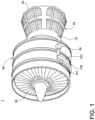
FIG. 1 is a schematic illustration of a gas turbine engine with an accessory gearbox in accordance with various aspects described herein. -
FIG. 2 is a sectional view of a starter/generator mounted to the accessory gearbox ofFIG. 1 by way of a rotating shaft, in accordance with various aspects described herein. -
FIG. 3 is an exploded view of a decoupler adapted for use with the starter/generator ofFIG. 2 in accordance with various aspects described herein. -
FIG. 4A is a cross-sectional view of the decoupler ofFIG. 3 in a first position relative to the rotating shaft, in accordance with various aspects described herein. -
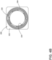
FIG. 4B is a top view of the decoupler ofFIG. 3 in a first position relative to the rotating shaft, in accordance with various aspects described herein. -
FIG. 5A is a cross-sectional view of the decoupler ofFIG. 3 in a second position relative to the rotating shaft, in accordance with various aspects described herein. -
FIG. 5B is a top view of the decoupler ofFIG. 3 in a second position relative to the rotating shaft, in accordance with various aspects described herein. -
FIG. 6 is a flow chart of a method for operating an air turbine starter. - The present invention is related to a driving mechanism generating kinetic motion in the form of a rotating shaft coupled with a piece of rotating equipment. One non-limiting example of a driving mechanism can include a gas turbine engine rotationally driving a piece of rotating equipment, such as a starter. The starter has various applications including starting a gas turbine engine and generating electrical power when the gas turbine engine is in operation. While the exemplary embodiment described herein is directed to application of a gas turbine engine and a starter, embodiments of the disclosure can be applied to any implementation of a driving mechanism that generates rotational motion at a driving output, and provides the rotational motion to another piece of rotating equipment.
- Referring to
FIG. 1 , a starter motor orair turbine starter 102 including an accessory gear box (AGB) 100, also known as a transmission housing, are schematically illustrated as being mounted to agas turbine engine 1. This assembly is commonly referred to as an Integrated Starter/Generator Gearbox (ISGB), or simply anair turbine starter 102. Thegas turbine engine 1 comprises an air intake with afan 50 that supplies air to a highpressure compression region 60. The air intake with afan 50 and the high pressure compression region collectively are known as the 'cold section' of the gas turbine engine upstream of the combustion. The highpressure compression region 60 provides thecombustion chamber 10 with high pressure air. In the combustion chamber, the high pressure air is mixed with fuel and combusted. The hot and pressurized combusted gas passes through a highpressure turbine region 20 and a lowpressure turbine region 30 before exhausting from the gas turbine engine. As the pressurized gases pass through the high pressure turbine (not shown) of the highpressure turbine region 20 and the low pressure turbine (not shown) of the lowpressure turbine region 30, the turbines extract rotational energy from the flow of the gases passing through thegas turbine engine 1. The high pressure turbine of the highpressure turbine region 20 can be coupled to the compression mechanism (not shown) of the highpressure compression region 60 by way of a shaft to power the compression mechanism. The low pressure turbine can be coupled to thefan 50 of the air intake by way of a shaft to power thefan 50. - The gas turbine engine can be a turbofan engine, such as a General Electric GEnx or CF6 series engine, commonly used in modern commercial and military aviation or it could be a variety of other known gas turbine engines such as a turboprop or turboshaft. The gas turbine engine can also have an afterburner that burns an additional amount of fuel downstream of the low
pressure turbine region 30 to increase the velocity of the exhausted gases, and thereby increasing thrust. - The AGB 100 is coupled to a turbine shaft of the
gas turbine engine 1, either to the low pressure or high pressure turbine by way of a mechanical power take-off 90. The mechanical power take off 90 contains multiple gears and means for mechanical coupling of the AGB 100 to thegas turbine engine 1. Theassembly 102 can be mounted on the outside of either the air intake region containing thefan 50 or on the core near the highpressure compression region 60. - Referring now to
FIG. 2 , theair turbine starter 102 is shown in greater detail. Generally, theair turbine starter 102 includes ahousing 108 defining aninlet 110, anoutlet 112, and aflow path 114 extending between theinlet 110 andoutlet 112 for communicating a flow of gas there through. Theair turbine starter 102 includes aturbine member 116 journaled within thehousing 108 and disposed within theflow path 114 for rotatably extracting mechanical power from the flow of gas along theflow path 114. Further, agear train 118, disposed within thegear box 101 and drivingly coupled with theturbine member 116, can be caused to rotate. - The
gear train 118 includes aring gear 120 and can further comprise any gear assembly including for example but not limited to a planetary gear assembly or a pinion gear assembly. Aturbine shaft 122 couples thegear train 118 to theturbine member 116 allowing for the transfer of mechanical power. Theturbine shaft 122 is rotatably mounted to thegear train 118 and supported by a pair ofturbine bearings 124 while thegear train 118 is supported by a pair ofcarrier bearings 126. - A
gear box interior 127 can contain oil to provide lubrication and cooling to mechanical parts contained therein such as thegear train 118,ring gear 120, andbearings - There is an
aperture 128 through which theturbine shaft 122 extends and meshes with acarrier shaft 130 to which aclutch 132 is mounted and supported by a pair of spacedbearings 134. Adrive shaft 136 extends from a portion of thegear box 101 and is coupled to theclutch 132 and additionally supported by the pair of spacedbearings 134. Thedrive shaft 136 is driven by thegear train 118 and coupled to the power take-off 90 of thegas turbine engine 1, such that operation of theengine 1 provides a driving motion to thegear box 101. - The
clutch 132 can be any type of shaft interface portion that forms a singlerotatable shaft 138 including theturbine shaft 122, thecarrier shaft 130, and thedrive shaft 136. The shaft interface portion can be by any known method of coupling including, but not limited to, gears, splines, a clutch mechanism, or combinations thereof. An example of ashaft interface portion 132 is disclosed inUnited States Patent No. 4,281,942 to General Electric . - The
gear box 101 and thestarter 102 can be formed by any known materials and methods, including, but not limited to, die-casting of high strength and lightweight metals such as aluminum, stainless steel, iron, or titanium. The housing for thegear box 101 andstarter 102 can be formed with a thickness sufficient to provide adequate mechanical rigidity without adding unnecessary weight to theassembly 102 and, therefore, the aircraft. - The
rotatable shaft 138 can be constructed by any known materials and methods, including, but not limited to extrusion or machining of high strength metal alloys such as those containing aluminum, iron, nickel, chromium, titanium, tungsten, vanadium, or molybdenum. The diameter of theturbine shaft 122,carrier shaft 130, anddrive shaft 136 can be fixed or vary along the length of therotatable shaft 138. The diameter can vary to accommodate different sizes, as well as rotor to stator spacing. - As described herein, either the
gear box 101 or thestarter 102 can be a driving mechanism for driving the rotation of therotating shafts starter 102 can be the driving mechanism for rotation of therotating shafts gas turbine engine 1 operation, thegear box 101 can be the driving mechanism for rotation of therotating shafts rotating shafts starter 102. - The
drive shaft 136 is further coupled to adecoupler assembly 190 including abackdrive decoupler 200 having anoutput shaft 202, configured to be operably coupled to and rotate with theengine 1, and atensile fuse 204. Thetensile fuse 204 is selectively receivable and axially moveable within an internal threadedportion 206, that can be for example a helical female thread, of theoutput shaft 202. All joining parts can be formed from steel or like materials. -
FIG. 3 illustrates an exploded perspective view of one exemplary embodiment of thedecoupler assembly 190 including thebackdrive decoupler 200 and thedrive shaft 136. Thedrive shaft 136 can include acircular depression 210 and anorthogonal depressions 212. Thecircular depression 210 is surrounded by theorthogonal depression 212. Acentral opening 214 is bound by acircular lip 216. Circumscribing thecircular lip 216 are a plurality ofstops 218. - A
thread insert 208 is included in thedecoupler assembly 190 and is illustrated as including a complementarycircular protrusion 220 andorthogonal portion 222 formed to fit into the circular and orthogonal shapeddepressions drive shaft 136. Thethread insert 208 further includes an internal helical threadedportion 224 which can be for example but not limited to a three helical female thread. - The
decoupler assembly 190 can also include acompression spring 217 and aring spring 228. - The
output shaft 202 includes afirst end 230 having an exteriorly threadedportion 234. The exteriorly threadedportion 234 can include, but is not limited to, a helical male thread, with a proximal end including complementary stops 236. Asecond end 232 is configured to be operably coupled to and rotate with theengine 1. - The
tensile fuse 204 includes a cylindricalfirst end 238. Asecond end 240 of thetensile fuse 204 includes ahead 242 and a threadedportion 244 that can be, for example, a helical male thread, disposed beneath thehead 242. Thetensile fuse 204 further includes aneck portion 246 having a reduced diameter between thefirst end 238 and the threadedportion 244. - The cylindrical
first end 238 is received in thecentral opening 214 where aretainer pin 239 retains thefirst end 238 of thetensile fuse 204 within thedrive shaft 136 operably coupling thetensile fuse 204 to thedrive shaft 136. At assembly thetensile fuse 204 can be drilled and pinned with theretainer pin 239. The threadedportion 244 disposed beneath thehead 242 is received within the internal threadedportion 206 of theoutput shaft 202 - The exteriorly threaded
portion 234 of theoutput shaft 202 and the internal threadedportion 206 of thetensile fuse 204 are formed so that thetensile fuse 204 is threaded into theoutput shaft 202 with an opposite hand turn compared to when theoutput shaft 202 is threaded into thethread insert 208. Thestops 218 andcomplementary stops 236 decrease axial loads along the threaded portions, 206, 224, 234, 244 when theoutput shaft 202 is fully threaded into thethread insert 208 of thedrive shaft 136. -
FIG. 4A illustrates thedecoupler assembly 190 mounted with thedrive shaft 136. Because thedrive shaft 136 and thethread insert 208 have correspondingcircular depression 210,orthogonal depressions 212 andcircular protrusion 220 andorthogonal portions 222, respectively, they can be operably coupled. Likewise, the complementary shapes of thestop drive shaft 136 to theoutput shaft 202. It should be understood that the shapes of the depressions and corresponding receiving portions depicted as orthogonal and circular and the shapes of the complementary stops are for illustrative purposes and not meant to be limiting. - A biasing mechanism can be included between the
thread insert 208 and thedrive shaft 136. In the illustrated example, the biasing mechanism is thecompression spring 217. - A load path can go through mating stop features including the
stops drive shaft 136 of the clutch 132 to theoutput shaft 202 to drive theengine 1 by the mating stop features 218, 236. The load path leaves the threaded portions, 206, 224, 234, 244, thetensile fuse 204, and theretainer pin 239 unloaded. - A top view of the
thread insert 208 inFIG. 4B illustrates thering spring 228. Under normal operating conditions the threads of the exteriorly threadedportion 234 push thering spring 228 outward into aninner portion 226 of thethread insert 208 in an expanded position. - When the clutch 132 becomes disengaged and the
engine 1 transmits an overrunning torque, having a magnitude below a certain level, to theair turbine starter 102 the mating stop features 218, 236 become unloaded while the threaded portions, 206, 224, 234, 244, thetensile fuse 204, andretainer pin 239 become partially loaded. - Turning to
FIG. 5A , in the event of a backdrive which can occur when the clutch 132 fails, theair turbine starter 102 decouples its load path so that components of thegear box 101 andstarter 102 are disconnected from theengine 1. The failingclutch 132 becomes engaged or locked while theengine 1 transmits an overrunning torque, with a magnitude of torque at or above the certain level, to theair turbine starter 102. This can also be considered a back driving torque. - In the case of the locked clutch, the
backdrive decoupler 200 would be exposed to enough drag torque that theoutput shaft 202 would unwind from thedrive shaft 136, and to simultaneously unwind thetensile fuse 204 from theoutput shaft 202. The thread ratios between the internal threadedportion 206 and the threadedportion 244 for thetensile fuse 204 compared to those between the internal threadedportion 224 and the threadedportion 234 for theoutput shaft 202 allow for thetensile fuse 204 to translate two times the translation distance of theoutput shaft 202, contributing to a high strain on theneck portion 246, causing it to shear and creating a shearedportion 250 and abase 252. The shearedportion 250 of thetensile fuse 204 is unwound from theoutput shaft 202 leaving the base 252 retained by theretainer pin 239. - The unwinding of the
output shaft 202 is further aided by thecompressive spring 217. When theoutput shaft 202 begins to unwind, thecompressive spring 217 is configured to expand and bias theoutput shaft 202 away from thedrive shaft 136. It will be understood that any suitable biasing mechanism can be utilized and that the compressive spring is one illustrated example. - A top view of the
thread insert 208 inFIG. 5B illustrates the movement of thering spring 228 in the event of a back drive. Because theoutput shaft 202 has translated, the threads of the exteriorly threadedportion 234 are no longer pushing thering spring 228 outward. This allows thering spring 228 to compress to a retracted position where thering spring 228 overlies a portion of thethread insert 208 preventing rethreading of thefirst end 230 of theoutput shaft 202 and thethread insert 208. In this manner, thering spring 228 is configured to secure theoutput shaft 202 in a decoupled and separate position from thedrive shaft 136. - A
method 400 for operating anair turbine starter 102 is outlined in a flow chart inFIG. 6 . Themethod 400 begins at 402 with extracting mechanical power from a flow of gas utilizing aturbine 116 and driving thegear train 118 and clutch 132, including thedrive shaft 136. At 404 a driving torque is transmitted from thedrive shaft 136 to anoutput shaft 202 which is operably coupled to theengine 1. - In the case of back driving at 406 the
backdrive decoupler 200 is activated when thetensile fuse 204 that is operably coupled to both theoutput shaft 202 and thedrive shaft 136 is sheared. The shearedportion 250 of thetensile fuse 204 is then unwound from theoutput shaft 202 and translated away from thedrive shaft 136. Theoutput shaft 202 is unwound from thedrive shaft 136 and translated away from thedrive shaft 136. - At 408 the
output shaft 202 is prevented from reengaging thedrive shaft 136 when thering spring 228 contracts. The contraction of thering spring 228 prevents theoutput shaft 202 from reengaging by blocking the internal helical threadedportion 224 from receiving the exteriorly threadedportion 234. Thecompression spring 217 is a secondary mechanism that also prevents reengagement when it has sprung. The springing of thecompression spring 217 biases the output shaft202 out and away from thedrive shaft 136. Theair turbine starter 102 is therefore disabled after decoupling, which prevents an additional engine start. - All directional references (e.g., radial, upper, lower, upward, downward, left, right, lateral, front, back, top, bottom, above, below, vertical, horizontal, clockwise, counterclockwise) are only used for identification purposes to aid the reader's understanding of the disclosure, and do not create limitations, particularly as to the position, orientation, or use thereof. Connection references (e.g., attached, coupled, connected, and joined) are to be construed broadly and can include intermediate members between a collection of elements and relative movement between elements unless otherwise indicated. As such, connection references do not necessarily infer that two elements are directly connected and in fixed relation to each other. The exemplary drawings are for purposes of illustration only and the dimensions, positions, order and relative sizes reflected in the drawings attached hereto can vary.
- Many other possible embodiments and configurations in addition to that shown in the above figures are contemplated by the present disclosure. Additionally, the design and placement of the various components such as starter, AGB, or components thereof can be rearranged such that a number of different in-line configurations could be realized.
- The aspects of the present disclosure provide a decoupler for decoupling a torque load coming from the gear train of an engine to prevent backdriving of the entire air turbine starter. Benefits associated with this decoupling include reducing the risk of spinning a damaged air turbine starter which could cause additional damage to the air turbine starter if not decoupled. Further still, the decoupling results in only the tensile fuse being needed to be replaced instead of more costly parts damaged by the continued backdriving.
- This written description uses examples to disclose embodiments of the invention, including the best mode, and also to enable any person skilled in the art to practice embodiments of the invention, including making and using any devices or systems and performing any incorporated methods. The patentable scope of the invention is defined by the claims.
Claims (12)
- An air turbine starter (102) for starting an engine (1), comprising:a housing (108) defining an inlet (110), an outlet (112), and a flow path (114) extending between the inlet and the outlet for communicating a flow of gas therethrough;a turbine member (116) journaled within the housing and disposed within the flow path for rotatably extracting mechanical power from the flow of gas;a gear train (118) drivingly coupled with the turbine member;a clutch (132) having a drive shaft (136) operably coupled with the gear train, and a thread insert (208) operably coupled to the drive shaft (136), the thread insert (208) comprising a threaded portion (224); anda decoupler (200), comprising:a tensile fuse (204) having a first end (238) operably coupled to the drive shaft, a threaded portion (244), and a neck portion (246) having a reduced diameter located between the first end and the threaded portion; andan output shaft (202) having a first end (230) selectively operably coupled to the drive shaft, a second end (232) configured to be operably coupled to and rotate with the engine, an exteriorly threaded portion (234) of the first end (230), and an internal threaded portion (206) that receives the threaded portion of the tensile fuse;wherein the threaded portion (224) of the thread insert (208) receives the exteriorly threaded portion (234) of the first end of the output shaft (202); andwherein when a driving torque is transmitted from the drive shaft of the clutch to the output shaft the tensile fuse is not loaded, when an overrunning torque is transmitted below a certain level the tensile fuse is partially loaded and when the overrunning torque reaches a certain level the tensile fuse shears at the neck portion and the threaded portion (244) of the tensile fuse (204) is unwound from the internal threaded portion (206) in a direction away from the drive shaft and the output shaft (202) is unwound from the thread insert (208) in a direction away from the drive shaft.
- The air turbine starter (102) of claim 1, wherein the tensile fuse (204) is threaded into the output shaft (202) with an opposite hand turn to the threads (230) between the output shaft (202) and the thread insert (208).
- The air turbine starter (102) of claim 2, wherein the tensile fuse translates two times the translation of the output shaft.
- The air turbine starter (102) of claim 2, further comprising a blocking mechanism (217) configured to bar the output shaft from rethreading with the thread insert.
- The air turbine starter (102) of claim 4, wherein the blocking mechanism (217) comprises a ring spring moveable between an expanded position where the ring spring is pushed outwards by the output shaft and a retracted position where the ring spring overlies a portion of the thread insert and is configured to prevent rethreading of the first end of the output shaft and the thread insert.
- The air turbine starter (102) of claim 2, further comprising a biasing mechanism (228) located between the drive shaft and the output shaft and configured to bias the output shaft away from the drive shaft.
- The air turbine starter (102) of claim 6, wherein the biasing mechanism (228) is a compressive spring.
- The air turbine starter (102) of claim 5, further comprising a retainer pin (239) retaining the first end of the tensile fuse within the drive shaft.
- The air turbine starter (102) of claim 5, wherein the driving torque is transmitted through mating stop features (218,236) on the drive shaft and the output shaft.
- A method for operating a starter according to any of claims 1 to 9, the method comprising:extracting mechanical power from a flow of gas utilizing a turbine and driving a gear train and clutch having a drive shaft therewith;transmitting a driving torque from the drive shaft to an output shaft operably coupled to an engine; andduring back driving, activating a backdrive decoupler wherein a tensile fuse operably coupled to the output shaft and the drive shaft is sheared and a sheared portion of the tensile fuse is unwound from the output shaft and translated away from the drive shaft and the output shaft is unwound from the thread insert and translated away from the drive shaft.
- The method of claim 10, wherein the tensile fuse translates two times the translation of the output shaft.
- The method of claim 10, further comprising preventing the output shaft from reengaging the drive shaft such that the starter motor is disabled after decoupling, which prevents an additional engine start.
Applications Claiming Priority (2)
| Application Number | Priority Date | Filing Date | Title |
|---|---|---|---|
| US15/180,728 US10584640B2 (en) | 2016-06-13 | 2016-06-13 | Air turbine starter with decoupler |
| PCT/US2017/037225 WO2017218514A1 (en) | 2016-06-13 | 2017-06-13 | Air turbine starter with decoupler |
Publications (2)
| Publication Number | Publication Date |
|---|---|
| EP3469202A1 EP3469202A1 (en) | 2019-04-17 |
| EP3469202B1 true EP3469202B1 (en) | 2024-11-13 |
Family
ID=59093640
Family Applications (1)
| Application Number | Title | Priority Date | Filing Date |
|---|---|---|---|
| EP17731999.3A Active EP3469202B1 (en) | 2016-06-13 | 2017-06-13 | Air turbine starter with decoupler |
Country Status (6)
| Country | Link |
|---|---|
| US (2) | US10584640B2 (en) |
| EP (1) | EP3469202B1 (en) |
| JP (1) | JP2019521285A (en) |
| CN (1) | CN109312667B (en) |
| CA (1) | CA3026750A1 (en) |
| WO (1) | WO2017218514A1 (en) |
Families Citing this family (10)
| Publication number | Priority date | Publication date | Assignee | Title |
|---|---|---|---|---|
| US20180030900A1 (en) * | 2016-08-01 | 2018-02-01 | Honeywell International Inc. | Air Turbine Starter with Integrated Motor for Main Engine Cooling |
| US10815897B2 (en) * | 2017-07-26 | 2020-10-27 | Unison Industries, Llc | Air turbine starter |
| US20190032566A1 (en) * | 2017-07-26 | 2019-01-31 | Unison Industries, Llc | Air turbine starter |
| PL433297A1 (en) | 2020-03-19 | 2021-09-20 | Unison Industries, Llc | Decoupling network for a motor starter |
| KR102935079B1 (en) * | 2020-04-22 | 2026-03-05 | 현대자동차주식회사 | Propelller shaft for vehicle |
| EP4545752A3 (en) | 2020-07-15 | 2025-06-25 | Unison Industries, LLC | Air starter with offset interface |
| PL434997A1 (en) * | 2020-08-18 | 2022-02-21 | Unison Industries, Llc | Air turbine starter |
| US11639669B2 (en) | 2021-02-08 | 2023-05-02 | General Electric Company | Systems and methods for selectively disconnecting embedded electrical machines in gas turbine engines |
| CN114233480A (en) * | 2021-12-13 | 2022-03-25 | 中国船舶重工集团公司第七0三研究所 | Gas turbine transmission system |
| US11959421B2 (en) | 2022-05-23 | 2024-04-16 | Unison Industries, Llc | Air turbine starter with decoupler |
Family Cites Families (16)
| Publication number | Priority date | Publication date | Assignee | Title |
|---|---|---|---|---|
| US2602335A (en) | 1951-03-23 | 1952-07-08 | Bendix Aviat Corp | Engine starter gearing |
| US2964931A (en) * | 1958-06-20 | 1960-12-20 | Garrett Corp | Reversible shear output shaft |
| US2951570A (en) | 1958-11-25 | 1960-09-06 | Gen Electric | Starter decoupling means |
| US3059085A (en) | 1959-09-18 | 1962-10-16 | Stevens Mfg Co Inc | Temperature control circuit |
| US3220218A (en) | 1963-12-30 | 1965-11-30 | Gen Electric | Device for disconnecting engine driven aircraft accessories |
| US4281942A (en) | 1978-11-13 | 1981-08-04 | General Electric Company | Lubrication system for high speed spline connection and bearing |
| FR2529976B1 (en) * | 1982-07-08 | 1986-11-28 | Hispano Suiza Sa | DEVICE FOR DECOUPLING TWO ROTATING MACHINES |
| US4601591A (en) * | 1984-05-14 | 1986-07-22 | The Garrett Corporation | Elastomeric bearing damper apparatus and associated methods |
| US4768634A (en) | 1986-12-22 | 1988-09-06 | Sundstrand Corporation | Backdrive overload release clutch |
| US4871296A (en) | 1988-11-07 | 1989-10-03 | Allied-Signal Inc. | Decoupler shaft and air turbine starter having such a decoupler |
| US6059085A (en) * | 1998-12-17 | 2000-05-09 | Alliedsignal Inc. | Shaft decoupler |
| CN1179118C (en) * | 1999-11-08 | 2004-12-08 | 罗桂荣 | Gas turbine |
| FR2845126B1 (en) * | 2002-09-26 | 2004-12-03 | Snecma Moteurs | TRACTION COUPLER DEVICE |
| FR2887945B1 (en) | 2005-06-30 | 2007-10-05 | Microturbo Sa | DECOUPLER SLEEVE |
| US8105018B2 (en) * | 2008-02-13 | 2012-01-31 | Honeywell International Inc. | Decoupler devices to prevent backdrive in air turbine starters |
| CN201535201U (en) * | 2009-09-03 | 2010-07-28 | 深圳市安托山特种机械有限公司 | Turbojet engine clutch |
-
2016
- 2016-06-13 US US15/180,728 patent/US10584640B2/en active Active
-
2017
- 2017-06-13 JP JP2019517199A patent/JP2019521285A/en not_active Ceased
- 2017-06-13 EP EP17731999.3A patent/EP3469202B1/en active Active
- 2017-06-13 CA CA3026750A patent/CA3026750A1/en not_active Abandoned
- 2017-06-13 WO PCT/US2017/037225 patent/WO2017218514A1/en not_active Ceased
- 2017-06-13 CN CN201780036864.0A patent/CN109312667B/en active Active
-
2020
- 2020-02-12 US US16/788,997 patent/US11053857B2/en active Active
Also Published As
| Publication number | Publication date |
|---|---|
| US20170356345A1 (en) | 2017-12-14 |
| JP2019521285A (en) | 2019-07-25 |
| US10584640B2 (en) | 2020-03-10 |
| CN109312667A (en) | 2019-02-05 |
| CN109312667B (en) | 2021-03-12 |
| WO2017218514A1 (en) | 2017-12-21 |
| CA3026750A1 (en) | 2017-12-21 |
| US11053857B2 (en) | 2021-07-06 |
| EP3469202A1 (en) | 2019-04-17 |
| US20200182156A1 (en) | 2020-06-11 |
Similar Documents
| Publication | Publication Date | Title |
|---|---|---|
| US11053857B2 (en) | Air turbine starter with decoupler | |
| EP3404234B1 (en) | Decoupler assemblies for engine starter | |
| US11352956B2 (en) | Air turbine starter with decoupler | |
| EP3401531A1 (en) | Air turbine starter comprising a planetary gear system | |
| EP3555446B1 (en) | Air turbine starter with decoupler | |
| US10526974B2 (en) | Decoupler assembly for engine starter | |
| US10690196B2 (en) | Shaft decoupler for electric generator | |
| EP3882447B1 (en) | Engine starter with a decoupler | |
| AU2022224828B9 (en) | Air turbine starter with decoupler |
Legal Events
| Date | Code | Title | Description |
|---|---|---|---|
| STAA | Information on the status of an ep patent application or granted ep patent |
Free format text: STATUS: UNKNOWN |
|
| STAA | Information on the status of an ep patent application or granted ep patent |
Free format text: STATUS: THE INTERNATIONAL PUBLICATION HAS BEEN MADE |
|
| PUAI | Public reference made under article 153(3) epc to a published international application that has entered the european phase |
Free format text: ORIGINAL CODE: 0009012 |
|
| STAA | Information on the status of an ep patent application or granted ep patent |
Free format text: STATUS: REQUEST FOR EXAMINATION WAS MADE |
|
| 17P | Request for examination filed |
Effective date: 20190114 |
|
| AK | Designated contracting states |
Kind code of ref document: A1 Designated state(s): AL AT BE BG CH CY CZ DE DK EE ES FI FR GB GR HR HU IE IS IT LI LT LU LV MC MK MT NL NO PL PT RO RS SE SI SK SM TR |
|
| AX | Request for extension of the european patent |
Extension state: BA ME |
|
| DAV | Request for validation of the european patent (deleted) | ||
| DAX | Request for extension of the european patent (deleted) | ||
| RIN1 | Information on inventor provided before grant (corrected) |
Inventor name: DRANSCHAK, DAVID, ALLAN Inventor name: MEYERS, SHILOH, MONTEGOMERY, EMERSON Inventor name: BULATHSINGHALAGE, HARSHA Inventor name: RODRIGUEZ, ELIEL, FRESCO |
|
| STAA | Information on the status of an ep patent application or granted ep patent |
Free format text: STATUS: EXAMINATION IS IN PROGRESS |
|
| 17Q | First examination report despatched |
Effective date: 20201029 |
|
| REG | Reference to a national code |
Ref legal event code: R079 Free format text: PREVIOUS MAIN CLASS: F02C0007268000 Ipc: F16D0009080000 Ref country code: DE Ref legal event code: R079 Ref document number: 602017086089 Country of ref document: DE Free format text: PREVIOUS MAIN CLASS: F02C0007268000 Ipc: F16D0009080000 |
|
| GRAP | Despatch of communication of intention to grant a patent |
Free format text: ORIGINAL CODE: EPIDOSNIGR1 |
|
| STAA | Information on the status of an ep patent application or granted ep patent |
Free format text: STATUS: GRANT OF PATENT IS INTENDED |
|
| RIC1 | Information provided on ipc code assigned before grant |
Ipc: F02C 7/36 20060101ALI20240514BHEP Ipc: F02C 7/275 20060101ALI20240514BHEP Ipc: F02C 7/32 20060101ALI20240514BHEP Ipc: F02C 7/268 20060101ALI20240514BHEP Ipc: F16D 9/08 20060101AFI20240514BHEP |
|
| INTG | Intention to grant announced |
Effective date: 20240612 |
|
| GRAS | Grant fee paid |
Free format text: ORIGINAL CODE: EPIDOSNIGR3 |
|
| GRAA | (expected) grant |
Free format text: ORIGINAL CODE: 0009210 |
|
| STAA | Information on the status of an ep patent application or granted ep patent |
Free format text: STATUS: THE PATENT HAS BEEN GRANTED |
|
| AK | Designated contracting states |
Kind code of ref document: B1 Designated state(s): AL AT BE BG CH CY CZ DE DK EE ES FI FR GB GR HR HU IE IS IT LI LT LU LV MC MK MT NL NO PL PT RO RS SE SI SK SM TR |
|
| REG | Reference to a national code |
Ref country code: GB Ref legal event code: FG4D |
|
| REG | Reference to a national code |
Ref country code: CH Ref legal event code: EP |
|
| REG | Reference to a national code |
Ref country code: DE Ref legal event code: R096 Ref document number: 602017086089 Country of ref document: DE |
|
| REG | Reference to a national code |
Ref country code: IE Ref legal event code: FG4D |
|
| P01 | Opt-out of the competence of the unified patent court (upc) registered |
Free format text: CASE NUMBER: APP_61243/2024 Effective date: 20241115 |
|
| REG | Reference to a national code |
Ref country code: LT Ref legal event code: MG9D |
|
| REG | Reference to a national code |
Ref country code: NL Ref legal event code: MP Effective date: 20241113 |
|
| PG25 | Lapsed in a contracting state [announced via postgrant information from national office to epo] |
Ref country code: HR Free format text: LAPSE BECAUSE OF FAILURE TO SUBMIT A TRANSLATION OF THE DESCRIPTION OR TO PAY THE FEE WITHIN THE PRESCRIBED TIME-LIMIT Effective date: 20241113 Ref country code: PT Free format text: LAPSE BECAUSE OF FAILURE TO SUBMIT A TRANSLATION OF THE DESCRIPTION OR TO PAY THE FEE WITHIN THE PRESCRIBED TIME-LIMIT Effective date: 20250313 Ref country code: IS Free format text: LAPSE BECAUSE OF FAILURE TO SUBMIT A TRANSLATION OF THE DESCRIPTION OR TO PAY THE FEE WITHIN THE PRESCRIBED TIME-LIMIT Effective date: 20250313 |
|
| PG25 | Lapsed in a contracting state [announced via postgrant information from national office to epo] |
Ref country code: FI Free format text: LAPSE BECAUSE OF FAILURE TO SUBMIT A TRANSLATION OF THE DESCRIPTION OR TO PAY THE FEE WITHIN THE PRESCRIBED TIME-LIMIT Effective date: 20241113 Ref country code: NL Free format text: LAPSE BECAUSE OF FAILURE TO SUBMIT A TRANSLATION OF THE DESCRIPTION OR TO PAY THE FEE WITHIN THE PRESCRIBED TIME-LIMIT Effective date: 20241113 |
|
| REG | Reference to a national code |
Ref country code: AT Ref legal event code: MK05 Ref document number: 1741885 Country of ref document: AT Kind code of ref document: T Effective date: 20241113 |
|
| PG25 | Lapsed in a contracting state [announced via postgrant information from national office to epo] |
Ref country code: BG Free format text: LAPSE BECAUSE OF FAILURE TO SUBMIT A TRANSLATION OF THE DESCRIPTION OR TO PAY THE FEE WITHIN THE PRESCRIBED TIME-LIMIT Effective date: 20241113 |
|
| PG25 | Lapsed in a contracting state [announced via postgrant information from national office to epo] |
Ref country code: ES Free format text: LAPSE BECAUSE OF FAILURE TO SUBMIT A TRANSLATION OF THE DESCRIPTION OR TO PAY THE FEE WITHIN THE PRESCRIBED TIME-LIMIT Effective date: 20241113 |
|
| PG25 | Lapsed in a contracting state [announced via postgrant information from national office to epo] |
Ref country code: NO Free format text: LAPSE BECAUSE OF FAILURE TO SUBMIT A TRANSLATION OF THE DESCRIPTION OR TO PAY THE FEE WITHIN THE PRESCRIBED TIME-LIMIT Effective date: 20250213 |
|
| PG25 | Lapsed in a contracting state [announced via postgrant information from national office to epo] |
Ref country code: GR Free format text: LAPSE BECAUSE OF FAILURE TO SUBMIT A TRANSLATION OF THE DESCRIPTION OR TO PAY THE FEE WITHIN THE PRESCRIBED TIME-LIMIT Effective date: 20250214 Ref country code: LV Free format text: LAPSE BECAUSE OF FAILURE TO SUBMIT A TRANSLATION OF THE DESCRIPTION OR TO PAY THE FEE WITHIN THE PRESCRIBED TIME-LIMIT Effective date: 20241113 Ref country code: AT Free format text: LAPSE BECAUSE OF FAILURE TO SUBMIT A TRANSLATION OF THE DESCRIPTION OR TO PAY THE FEE WITHIN THE PRESCRIBED TIME-LIMIT Effective date: 20241113 |
|
| PG25 | Lapsed in a contracting state [announced via postgrant information from national office to epo] |
Ref country code: PL Free format text: LAPSE BECAUSE OF FAILURE TO SUBMIT A TRANSLATION OF THE DESCRIPTION OR TO PAY THE FEE WITHIN THE PRESCRIBED TIME-LIMIT Effective date: 20241113 |
|
| PG25 | Lapsed in a contracting state [announced via postgrant information from national office to epo] |
Ref country code: RS Free format text: LAPSE BECAUSE OF FAILURE TO SUBMIT A TRANSLATION OF THE DESCRIPTION OR TO PAY THE FEE WITHIN THE PRESCRIBED TIME-LIMIT Effective date: 20250213 |
|
| PG25 | Lapsed in a contracting state [announced via postgrant information from national office to epo] |
Ref country code: SM Free format text: LAPSE BECAUSE OF FAILURE TO SUBMIT A TRANSLATION OF THE DESCRIPTION OR TO PAY THE FEE WITHIN THE PRESCRIBED TIME-LIMIT Effective date: 20241113 |
|
| PGFP | Annual fee paid to national office [announced via postgrant information from national office to epo] |
Ref country code: DE Payment date: 20250520 Year of fee payment: 9 |
|
| PG25 | Lapsed in a contracting state [announced via postgrant information from national office to epo] |
Ref country code: DK Free format text: LAPSE BECAUSE OF FAILURE TO SUBMIT A TRANSLATION OF THE DESCRIPTION OR TO PAY THE FEE WITHIN THE PRESCRIBED TIME-LIMIT Effective date: 20241113 |
|
| PGFP | Annual fee paid to national office [announced via postgrant information from national office to epo] |
Ref country code: GB Payment date: 20250520 Year of fee payment: 9 |
|
| PG25 | Lapsed in a contracting state [announced via postgrant information from national office to epo] |
Ref country code: EE Free format text: LAPSE BECAUSE OF FAILURE TO SUBMIT A TRANSLATION OF THE DESCRIPTION OR TO PAY THE FEE WITHIN THE PRESCRIBED TIME-LIMIT Effective date: 20241113 |
|
| PGFP | Annual fee paid to national office [announced via postgrant information from national office to epo] |
Ref country code: FR Payment date: 20250520 Year of fee payment: 9 |
|
| PG25 | Lapsed in a contracting state [announced via postgrant information from national office to epo] |
Ref country code: RO Free format text: LAPSE BECAUSE OF FAILURE TO SUBMIT A TRANSLATION OF THE DESCRIPTION OR TO PAY THE FEE WITHIN THE PRESCRIBED TIME-LIMIT Effective date: 20241113 |
|
| PG25 | Lapsed in a contracting state [announced via postgrant information from national office to epo] |
Ref country code: SK Free format text: LAPSE BECAUSE OF FAILURE TO SUBMIT A TRANSLATION OF THE DESCRIPTION OR TO PAY THE FEE WITHIN THE PRESCRIBED TIME-LIMIT Effective date: 20241113 |
|
| PG25 | Lapsed in a contracting state [announced via postgrant information from national office to epo] |
Ref country code: CZ Free format text: LAPSE BECAUSE OF FAILURE TO SUBMIT A TRANSLATION OF THE DESCRIPTION OR TO PAY THE FEE WITHIN THE PRESCRIBED TIME-LIMIT Effective date: 20241113 |
|
| PG25 | Lapsed in a contracting state [announced via postgrant information from national office to epo] |
Ref country code: IT Free format text: LAPSE BECAUSE OF FAILURE TO SUBMIT A TRANSLATION OF THE DESCRIPTION OR TO PAY THE FEE WITHIN THE PRESCRIBED TIME-LIMIT Effective date: 20241113 |
|
| REG | Reference to a national code |
Ref country code: DE Ref legal event code: R097 Ref document number: 602017086089 Country of ref document: DE |
|
| PG25 | Lapsed in a contracting state [announced via postgrant information from national office to epo] |
Ref country code: SE Free format text: LAPSE BECAUSE OF FAILURE TO SUBMIT A TRANSLATION OF THE DESCRIPTION OR TO PAY THE FEE WITHIN THE PRESCRIBED TIME-LIMIT Effective date: 20241113 |
|
| PLBE | No opposition filed within time limit |
Free format text: ORIGINAL CODE: 0009261 |
|
| STAA | Information on the status of an ep patent application or granted ep patent |
Free format text: STATUS: NO OPPOSITION FILED WITHIN TIME LIMIT |
|
| 26N | No opposition filed |
Effective date: 20250814 |
|
| REG | Reference to a national code |
Ref country code: CH Ref legal event code: H13 Free format text: ST27 STATUS EVENT CODE: U-0-0-H10-H13 (AS PROVIDED BY THE NATIONAL OFFICE) Effective date: 20260127 |
|
| PG25 | Lapsed in a contracting state [announced via postgrant information from national office to epo] |
Ref country code: MC Free format text: LAPSE BECAUSE OF FAILURE TO SUBMIT A TRANSLATION OF THE DESCRIPTION OR TO PAY THE FEE WITHIN THE PRESCRIBED TIME-LIMIT Effective date: 20241113 |
|
| PG25 | Lapsed in a contracting state [announced via postgrant information from national office to epo] |
Ref country code: LU Free format text: LAPSE BECAUSE OF NON-PAYMENT OF DUE FEES Effective date: 20250613 |
|
| REG | Reference to a national code |
Ref country code: BE Ref legal event code: MM Effective date: 20250630 |
|
| PG25 | Lapsed in a contracting state [announced via postgrant information from national office to epo] |
Ref country code: IE Free format text: LAPSE BECAUSE OF NON-PAYMENT OF DUE FEES Effective date: 20250613 |
|
| PG25 | Lapsed in a contracting state [announced via postgrant information from national office to epo] |
Ref country code: BE Free format text: LAPSE BECAUSE OF NON-PAYMENT OF DUE FEES Effective date: 20250630 |
|
| PG25 | Lapsed in a contracting state [announced via postgrant information from national office to epo] |
Ref country code: CH Free format text: LAPSE BECAUSE OF NON-PAYMENT OF DUE FEES Effective date: 20250630 |