EP3468818B1 - Front suspension system - Google Patents
Front suspension system Download PDFInfo
- Publication number
- EP3468818B1 EP3468818B1 EP17733534.6A EP17733534A EP3468818B1 EP 3468818 B1 EP3468818 B1 EP 3468818B1 EP 17733534 A EP17733534 A EP 17733534A EP 3468818 B1 EP3468818 B1 EP 3468818B1
- Authority
- EP
- European Patent Office
- Prior art keywords
- axle
- leaf spring
- chassis
- vehicle
- support element
- Prior art date
- Legal status (The legal status is an assumption and is not a legal conclusion. Google has not performed a legal analysis and makes no representation as to the accuracy of the status listed.)
- Active
Links
Images
Classifications
-
- B—PERFORMING OPERATIONS; TRANSPORTING
- B60—VEHICLES IN GENERAL
- B60G—VEHICLE SUSPENSION ARRANGEMENTS
- B60G11/00—Resilient suspensions characterised by arrangement, location or kind of springs
- B60G11/32—Resilient suspensions characterised by arrangement, location or kind of springs having springs of different kinds
- B60G11/34—Resilient suspensions characterised by arrangement, location or kind of springs having springs of different kinds including leaf springs
- B60G11/46—Resilient suspensions characterised by arrangement, location or kind of springs having springs of different kinds including leaf springs and also fluid springs
- B60G11/465—Resilient suspensions characterised by arrangement, location or kind of springs having springs of different kinds including leaf springs and also fluid springs with a flexible wall
-
- B—PERFORMING OPERATIONS; TRANSPORTING
- B60—VEHICLES IN GENERAL
- B60G—VEHICLE SUSPENSION ARRANGEMENTS
- B60G17/00—Resilient suspensions having means for adjusting the spring or vibration-damper characteristics, for regulating the distance between a supporting surface and a sprung part of vehicle or for locking suspension during use to meet varying vehicular or surface conditions, e.g. due to speed or load
- B60G17/015—Resilient suspensions having means for adjusting the spring or vibration-damper characteristics, for regulating the distance between a supporting surface and a sprung part of vehicle or for locking suspension during use to meet varying vehicular or surface conditions, e.g. due to speed or load the regulating means comprising electric or electronic elements
- B60G17/016—Resilient suspensions having means for adjusting the spring or vibration-damper characteristics, for regulating the distance between a supporting surface and a sprung part of vehicle or for locking suspension during use to meet varying vehicular or surface conditions, e.g. due to speed or load the regulating means comprising electric or electronic elements characterised by their responsiveness, when the vehicle is travelling, to specific motion, a specific condition, or driver input
-
- B—PERFORMING OPERATIONS; TRANSPORTING
- B60—VEHICLES IN GENERAL
- B60G—VEHICLE SUSPENSION ARRANGEMENTS
- B60G5/00—Resilient suspensions for a set of tandem wheels or axles having interrelated movements
-
- B—PERFORMING OPERATIONS; TRANSPORTING
- B60—VEHICLES IN GENERAL
- B60G—VEHICLE SUSPENSION ARRANGEMENTS
- B60G2202/00—Indexing codes relating to the type of spring, damper or actuator
- B60G2202/10—Type of spring
- B60G2202/11—Leaf spring
- B60G2202/112—Leaf spring longitudinally arranged
-
- B—PERFORMING OPERATIONS; TRANSPORTING
- B60—VEHICLES IN GENERAL
- B60G—VEHICLE SUSPENSION ARRANGEMENTS
- B60G2202/00—Indexing codes relating to the type of spring, damper or actuator
- B60G2202/10—Type of spring
- B60G2202/15—Fluid spring
- B60G2202/152—Pneumatic spring
-
- B—PERFORMING OPERATIONS; TRANSPORTING
- B60—VEHICLES IN GENERAL
- B60G—VEHICLE SUSPENSION ARRANGEMENTS
- B60G2204/00—Indexing codes related to suspensions per se or to auxiliary parts
- B60G2204/10—Mounting of suspension elements
- B60G2204/12—Mounting of springs or dampers
- B60G2204/121—Mounting of leaf springs
-
- B—PERFORMING OPERATIONS; TRANSPORTING
- B60—VEHICLES IN GENERAL
- B60G—VEHICLE SUSPENSION ARRANGEMENTS
- B60G2400/00—Indexing codes relating to detected, measured or calculated conditions or factors
- B60G2400/60—Load
- B60G2400/61—Load distribution
-
- B—PERFORMING OPERATIONS; TRANSPORTING
- B60—VEHICLES IN GENERAL
- B60G—VEHICLE SUSPENSION ARRANGEMENTS
- B60G2500/00—Indexing codes relating to the regulated action or device
- B60G2500/30—Height or ground clearance
Definitions
- the present invention relates to a front suspension system, in particular of an industrial vehicle comprising two front axles.
- Heavy-duty industrial vehicles are provided with two front axles, both steering.
- the second is connected to the chassis through a dedicated suspension in order to bear higher load.
- Document DE 299 07 673 U1 discloses a commercial vehicle at a reduced cost on the basis of existing vehicles.
- the invention provides that in an existing commercial truck, a driven with a linkage control second front axle is installed, wherein preferably the existing first front axle of the truck is placed in the installation of the second front axle in a relation to the original position forward offset position.
- the main aim of the present invention to provide a suspension scheme implemented for both the front axle capable to improve the drivability of the vehicle and to reduce the above problems/drawbacks.
- the main principle of the invention is to combine air bellows with guided spring leafs.
- the air bellows are controlled in order to evenly distribute the load between both the two front axles.
- a first object of the present invention is a front suspension system for a two front axle industrial vehicle.
- Another object of the present invention is a vehicle comprising such front suspension system.
- the present invention not only permits to better distribute the load and consequently the wear of the tyre on both the front axles, but, in case the vehicle is capable to control the height of the chassis, being the two front axles suspensions identical between each other, also the height control is easiest in view of the fact that the geometries of the suspension do not introduce uneven distribution of load with the height variation. Analogously, also the stiffness variation of the bellows reaction does not introduce uneven distribution of load.
- the attached claims describe preferred embodiments of the invention, forming an integral part of the present description.
- second element does not imply the presence of a "first element”, first, second, etc.. are used only for improving the clarity of the description and they should not be interpreted in a limiting way.
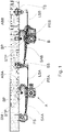
- Figure 1 discloses a front suspension system according to the present invention.
- the suspension system comprises two front axles A and B anchored to the side members SM defining the chassis of the industrial vehicle.
- Both axles are steering, even if they could assume different steering angles: usually the second axle assume a relative reduced steering angle in comparison with the first one.
- the ends of the side members SM depicted on the left side of figures 1 - 3 are shaped to support an internal combustion engine and a cab where a dashboard and controls are arranged.
- the axle A is the first front axle and the axle B is the second one arranged just behind the axle A.
- the suspension system comprises, for each side of the vehicle, two leaf springs LSA and LSB arranged longitudinally, namely substantially parallel to the side member, one for each axle A and B.
- the first leaf spring LSA is anchored, at its opposite ends, to the side member SM by means of a first support FS and a second support SS.
- a first swinging arm SAA having an elongated shape, has a first end hinged to the first support FS and a second end fixedly connected with an intermediate region of the first leaf spring LSA and with one end of the first axle A. Therefore, the first support defines a coaxial hinge for both the first leaf spring and its swinging arm.
- the bellow ABA is arranged between the leaf spring and its corresponding side member, in order to control the relative approaching/removal movement of the axle A with respect to the vehicle chassis.
- said fixed connection is realized by means of strips STP per se known in order to pack together axles and leaf springs.
- the second support SS defines two parallel hinges: one to support a second end of the first leaf spring LSA and another to support a first end of the second leaf spring LSB and its corresponding second swinging arm SAB.
- the construction of the second suspension is substantially identical to the first one.
- a third support TS connect the second end of the second leaf spring LSB by defining a further hinge.
- All the hinges have axes perpendicular to the longitudinal development of the side members.
- the second end of the first swinging arm SAA is also connected to the side member SM though a first bellow ABA interposed between said end and the side member.
- the second arm of the second swinging arm SAB is also connected to the side member SM though a second bellow ABB interposed between said end and the side member.
- the first support FS is connected to the side member internally, namely the face of the side member oriented toward the other side member.
- the second SS support element is perfectly under the side member, while the third TS support element is connected to the external face of the side member.
- the bellows are air bellow or hydro-pneumatic bellow.
- the bellows are directly connected to corresponding swinging arms SAA, SAB, namely without any carriers.
- the second axle B is of the driving type
- first axle A is of the driven type therefore, in the figures a differential arrangement is disclosed to distribute torque over the wheels.
- both the axles are of the driving type, thus both are provided of a central differential to receive propulsion by the internal combustion engine of the like through a transmission shaft.
- first axle A could be provided of hydraulic engine in the hubs, while the second axle B could be driven by the internal combustion engine through a transmission shaft.
- bumper BP are connected on the side members, protruding downwards, comprising resilient elements arranged in order to stop the second ends of the swinging arms SAA and SAB while approaching the chassis.
Landscapes
- Engineering & Computer Science (AREA)
- Mechanical Engineering (AREA)
- Vehicle Body Suspensions (AREA)
Description
- The present invention relates to a front suspension system, in particular of an industrial vehicle comprising two front axles.
- Heavy-duty industrial vehicles are provided with two front axles, both steering.
- Usually the second is connected to the chassis through a dedicated suspension in order to bear higher load.
- However, an uneven load distribution can arise with a poor drivability of the vehicle. Other negative effects are a poor braking action and an uneven tyre wear.
- Document
DE 299 07 673 U1 discloses a commercial vehicle at a reduced cost on the basis of existing vehicles. To achieve this object, the invention provides that in an existing commercial truck, a driven with a linkage control second front axle is installed, wherein preferably the existing first front axle of the truck is placed in the installation of the second front axle in a relation to the original position forward offset position. - The main aim of the present invention to provide a suspension scheme implemented for both the front axle capable to improve the drivability of the vehicle and to reduce the above problems/drawbacks.
- The main principle of the invention is to combine air bellows with guided spring leafs.
- In addition, the air bellows are controlled in order to evenly distribute the load between both the two front axles.
- A first object of the present invention is a front suspension system for a two front axle industrial vehicle. Another object of the present invention is a vehicle comprising such front suspension system.
- Advantageously, the present invention, not only permits to better distribute the load and consequently the wear of the tyre on both the front axles, but, in case the vehicle is capable to control the height of the chassis, being the two front axles suspensions identical between each other, also the height control is easiest in view of the fact that the geometries of the suspension do not introduce uneven distribution of load with the height variation. Analogously, also the stiffness variation of the bellows reaction does not introduce uneven distribution of load. The attached claims describe preferred embodiments of the invention, forming an integral part of the present description.
- The invention will become fully clear from the following detailed description, given by way of a mere exemplifying and non limiting example, to be read with reference to the attached executive drawing figures, wherein:
-
Fig. 1 shows a side view of the front suspension system, -
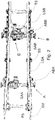
Fig. 2 shows a top view of the front suspension system offigure 1 ; -
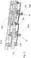
Fig. 3 shows a perspective view of the front suspension system offigure 1 . - The same reference numerals and letters in the figures designate the same or functionally equivalent parts.
- According to the present invention, the term "second element" does not imply the presence of a "first element", first, second, etc.. are used only for improving the clarity of the description and they should not be interpreted in a limiting way.
-
Figure 1 discloses a front suspension system according to the present invention. - The suspension system comprises two front axles A and B anchored to the side members SM defining the chassis of the industrial vehicle.
- Both axles are steering, even if they could assume different steering angles: usually the second axle assume a relative reduced steering angle in comparison with the first one.
- The ends of the side members SM depicted on the left side of
figures 1 - 3 are shaped to support an internal combustion engine and a cab where a dashboard and controls are arranged. Thus, the axle A is the first front axle and the axle B is the second one arranged just behind the axle A. - The suspension system comprises, for each side of the vehicle, two leaf springs LSA and LSB arranged longitudinally, namely substantially parallel to the side member, one for each axle A and B.
- The first leaf spring LSA is anchored, at its opposite ends, to the side member SM by means of a first support FS and a second support SS.
- A first swinging arm SAA, having an elongated shape, has a first end hinged to the first support FS and a second end fixedly connected with an intermediate region of the first leaf spring LSA and with one end of the first axle A. Therefore, the first support defines a coaxial hinge for both the first leaf spring and its swinging arm. The bellow ABA is arranged between the leaf spring and its corresponding side member, in order to control the relative approaching/removal movement of the axle A with respect to the vehicle chassis.
- Preferably, said fixed connection is realized by means of strips STP per se known in order to pack together axles and leaf springs.
- The second support SS defines two parallel hinges: one to support a second end of the first leaf spring LSA and another to support a first end of the second leaf spring LSB and its corresponding second swinging arm SAB. The construction of the second suspension is substantially identical to the first one.
- A third support TS connect the second end of the second leaf spring LSB by defining a further hinge.
- All the hinges have axes perpendicular to the longitudinal development of the side members.
- The second end of the first swinging arm SAA is also connected to the side member SM though a first bellow ABA interposed between said end and the side member. Analogously the second arm of the second swinging arm SAB is also connected to the side member SM though a second bellow ABB interposed between said end and the side member. According to
figure 3 , it is clear that the side member diverge between each other in order to offer a larger room to the combustion engine. - Therefore, the first support FS is connected to the side member internally, namely the face of the side member oriented toward the other side member.
- The second SS support element is perfectly under the side member, while the third TS support element is connected to the external face of the side member.
- According to a preferred embodiment of the invention, the bellows are air bellow or hydro-pneumatic bellow. Preferably, the bellows are directly connected to corresponding swinging arms SAA, SAB, namely without any carriers.
- Anyway, it is preferred the implementation of an automated load distribution between the axles A and B as the load distribution means usually adopted in the rear axles of the industrial vehicles.
- Preferably, the second axle B is of the driving type, and first axle A is of the driven type therefore, in the figures a differential arrangement is disclosed to distribute torque over the wheels.
- According to another configuration, both the axles are of the driving type, thus both are provided of a central differential to receive propulsion by the internal combustion engine of the like through a transmission shaft. However, other configuration can be foresee, for example the first axle A could be provided of hydraulic engine in the hubs, while the second axle B could be driven by the internal combustion engine through a transmission shaft.
- Preferably, in order to avoid any collisions between the axles and the side members, bumper BP are connected on the side members, protruding downwards, comprising resilient elements arranged in order to stop the second ends of the swinging arms SAA and SAB while approaching the chassis.
- Many changes, modifications, variations and other uses and applications of the subject invention will become apparent to those skilled in the art after considering the specification and the accompanying drawings, which disclose preferred embodiments thereof. All such changes, modifications, variations and other uses and applications do not depart from the scope of the invention are deemed to be covered by this invention as disclosed in the claims.
Claims (9)
- Front suspension system for industrial vehicles comprising two frontal axles (A, B) a first axle (A) and a second axle (B) arranged just behind the first axle (A), both connected to a vehicle chassis (SM), wherein the suspension system comprises for each side of the vehicle:- two consecutive leaf springs (LSA, LSB), one for each of said axles (A, B), wherein each leaf spring has a first end and an opposite second end hinged to the vehicle chassis,- a swinging arm (SAA, SAB) for each axle,- a bellow (ABA, ABB) for each axle interposed between the leaf spring and the vehicle chassis,said first end of the second leaf spring (LSB) of the second axle (B) being hinged to the chassis by means of a first support element (SS), and wherein said corresponding swinging arm (SAB) has a first end also hinged to the vehicle chassis by means of said first support element (SS), thereby said first and second leaf spring are consecutive due to said common first support element (SS);
characterized in that each said swinging arm (SAA, SAB) has a first end hinged to the vehicle chassis and a second end fixedly connected with an intermediate region of the leaf spring and with one end of the corresponding axle;
said system further comprising bumpers (BP) connectable to side members of said vehicle, protruding in use downwards, and comprising, in turn, resilient elements to stop said second ends of said swinging arms (SAA, SAB) while approaching said chassis;
each said bellow (ABA, ABB) being interposed between said second ends of said swinging arms (SAA, SAB) and a side member of said vehicle. - System according to claim 1, wherein said bellow is an air bellow or a hydro-pneumatic bellow.
- System according to claim 1 or 2, wherein said first end of the first leaf spring (LSA) of the first axle (A) is hinged to the chassis by means of a second support element (FS) and wherein said corresponding swinging arm (SAA) has a first end also hinged to the vehicle chassis by means of said second support element (FS).
- System according to claim 3, wherein said first and/or second support element define a first common hinge for said first end of said first leaf spring and said first end of said first swinging arm and/or a second common hinge for said first end of said second leaf spring and said first end of said second swinging arm.
- System according to previous claim 4, wherein said first leaf spring has a second end hinged to the vehicle chassis by means of said second support element defining a third hinge parallel to said second hinge.
- System according to previous claims 3 - 5 , wherein said second leaf spring has a second end hinged to the vehicle chassis by means of a third support element (TS) defining a fourth hinge.
- System according to anyone of the previous claims 1 - 6, further comprising load distribution means operatively associated with said first and second bellows (ABA, ABB) configured to evenly distribute a load over said first and second axles.
- System according to claim 7, further comprising means for varying stiffness and/or height of said first and second axles (A, B) by maintaining an evenly distribution of load over said first and second axles.
- Industrial vehicle having a chassis, two front axles (A, B): a first axle (A) and a second axle (B) arranged just behind the first axle (A), both connected to said chassis (SM), wherein the suspension system is according to anyone of previous claims 1 - 8.
Applications Claiming Priority (2)
| Application Number | Priority Date | Filing Date | Title |
|---|---|---|---|
| ITUA2016A004285A ITUA20164285A1 (en) | 2016-06-10 | 2016-06-10 | FRONT SUSPENSION SYSTEM |
| PCT/IB2017/053429 WO2017212455A1 (en) | 2016-06-10 | 2017-06-09 | Front suspension system |
Publications (2)
| Publication Number | Publication Date |
|---|---|
| EP3468818A1 EP3468818A1 (en) | 2019-04-17 |
| EP3468818B1 true EP3468818B1 (en) | 2021-03-31 |
Family
ID=57113621
Family Applications (1)
| Application Number | Title | Priority Date | Filing Date |
|---|---|---|---|
| EP17733534.6A Active EP3468818B1 (en) | 2016-06-10 | 2017-06-09 | Front suspension system |
Country Status (4)
| Country | Link |
|---|---|
| EP (1) | EP3468818B1 (en) |
| ES (1) | ES2870569T3 (en) |
| IT (1) | ITUA20164285A1 (en) |
| WO (1) | WO2017212455A1 (en) |
Family Cites Families (4)
| Publication number | Priority date | Publication date | Assignee | Title |
|---|---|---|---|---|
| FR2529838B1 (en) * | 1982-07-12 | 1987-02-27 | Renault Vehicules Ind | PNEUMATIC SUSPENSION DEVICE FOR INDUSTRIAL VEHICLE |
| DE3825105A1 (en) * | 1988-07-23 | 1990-02-08 | Iveco Magirus | SPRING AXLE SUSPENSION FOR MOTOR VEHICLES, IN PARTICULAR COMMERCIAL VEHICLES |
| DE29907673U1 (en) * | 1999-04-30 | 1999-08-12 | Paul, Josef, 94474 Vilshofen | Commercial vehicle, in particular disposal vehicle |
| SE527862C2 (en) * | 2005-03-02 | 2006-06-27 | Volvo Lastvagnar Ab | Load carrying vehicle`s e.g. dump truck, suspension arrangement, has controllable valves arranged to open for supplying air to balance pressure in suspension air spring and pressure in lifting air spring |
-
2016
- 2016-06-10 IT ITUA2016A004285A patent/ITUA20164285A1/en unknown
-
2017
- 2017-06-09 ES ES17733534T patent/ES2870569T3/en active Active
- 2017-06-09 EP EP17733534.6A patent/EP3468818B1/en active Active
- 2017-06-09 WO PCT/IB2017/053429 patent/WO2017212455A1/en not_active Ceased
Non-Patent Citations (1)
| Title |
|---|
| None * |
Also Published As
| Publication number | Publication date |
|---|---|
| ITUA20164285A1 (en) | 2017-12-10 |
| WO2017212455A1 (en) | 2017-12-14 |
| ES2870569T3 (en) | 2021-10-27 |
| EP3468818A1 (en) | 2019-04-17 |
Similar Documents
| Publication | Publication Date | Title |
|---|---|---|
| US8177245B2 (en) | Twist-beam rear axle comprising an additional Watt linkage | |
| EP2282911B1 (en) | Dual leaf vehicle suspension with j-shaped spring element | |
| US20140291951A1 (en) | Independent wheel suspension for the non-driven wheels of a vehicle | |
| CN110116755A (en) | Motor vehicles rear-wheel has Individual wheel suspension device of the driving wheel away from control function | |
| GB2396140A (en) | A cast suspension trailing arm for heavy commercial vehicles | |
| CN101648576B (en) | Vehicle frame with optional back suspension | |
| CA2682133A1 (en) | Separated primary spring and secondary leaf suspension for vehicle | |
| EP3233542B1 (en) | Vehicle suspension comprising a leaf spring assembly | |
| US20170305222A1 (en) | Wheel suspension with centrally pivoted transverse leaf spring | |
| US20130049318A1 (en) | Suspension structure for multi-purpose utility vehicle | |
| CN202389141U (en) | Wheel suspension frame | |
| CN104325852A (en) | Dragging arm | |
| US20200156427A1 (en) | Vehicle suspension assembly | |
| EP0435918B1 (en) | A leaf spring | |
| CN105015298A (en) | Front-engine front-drive double-transverse-arm independent suspension rack assembly of torsion rod spring | |
| EP2990239B1 (en) | Semitrailer equipped with independent wheel suspension and air springs | |
| EP3468818A1 (en) | Front suspension system | |
| US20140062049A1 (en) | Opposed Triangulated 4-Link Suspension System | |
| CN102862454B (en) | For the wheel suspension with cross force compensation of motor vehicles | |
| CN103287206A (en) | Arrangement form of truck chassis axle | |
| CN212637077U (en) | Automobile torsion beam rear axle | |
| US8955860B2 (en) | Vehicle suspension assembly with integrated torque member and trailing arm mount | |
| CN201900950U (en) | Multi-link rear suspension used on automobile | |
| CN205417067U (en) | Front suspension device of two front axle tractors | |
| CN204845423U (en) | Spring tray and turn round roof beam assembly |
Legal Events
| Date | Code | Title | Description |
|---|---|---|---|
| STAA | Information on the status of an ep patent application or granted ep patent |
Free format text: STATUS: UNKNOWN |
|
| STAA | Information on the status of an ep patent application or granted ep patent |
Free format text: STATUS: THE INTERNATIONAL PUBLICATION HAS BEEN MADE |
|
| PUAI | Public reference made under article 153(3) epc to a published international application that has entered the european phase |
Free format text: ORIGINAL CODE: 0009012 |
|
| STAA | Information on the status of an ep patent application or granted ep patent |
Free format text: STATUS: REQUEST FOR EXAMINATION WAS MADE |
|
| 17P | Request for examination filed |
Effective date: 20181210 |
|
| AK | Designated contracting states |
Kind code of ref document: A1 Designated state(s): AL AT BE BG CH CY CZ DE DK EE ES FI FR GB GR HR HU IE IS IT LI LT LU LV MC MK MT NL NO PL PT RO RS SE SI SK SM TR |
|
| AX | Request for extension of the european patent |
Extension state: BA ME |
|
| DAV | Request for validation of the european patent (deleted) | ||
| DAX | Request for extension of the european patent (deleted) | ||
| STAA | Information on the status of an ep patent application or granted ep patent |
Free format text: STATUS: EXAMINATION IS IN PROGRESS |
|
| 17Q | First examination report despatched |
Effective date: 20200414 |
|
| GRAP | Despatch of communication of intention to grant a patent |
Free format text: ORIGINAL CODE: EPIDOSNIGR1 |
|
| STAA | Information on the status of an ep patent application or granted ep patent |
Free format text: STATUS: GRANT OF PATENT IS INTENDED |
|
| GRAS | Grant fee paid |
Free format text: ORIGINAL CODE: EPIDOSNIGR3 |
|
| INTG | Intention to grant announced |
Effective date: 20210128 |
|
| GRAA | (expected) grant |
Free format text: ORIGINAL CODE: 0009210 |
|
| STAA | Information on the status of an ep patent application or granted ep patent |
Free format text: STATUS: THE PATENT HAS BEEN GRANTED |
|
| AK | Designated contracting states |
Kind code of ref document: B1 Designated state(s): AL AT BE BG CH CY CZ DE DK EE ES FI FR GB GR HR HU IE IS IT LI LT LU LV MC MK MT NL NO PL PT RO RS SE SI SK SM TR |
|
| REG | Reference to a national code |
Ref country code: GB Ref legal event code: FG4D Ref country code: CH Ref legal event code: EP |
|
| REG | Reference to a national code |
Ref country code: DE Ref legal event code: R096 Ref document number: 602017035668 Country of ref document: DE Ref country code: AT Ref legal event code: REF Ref document number: 1376529 Country of ref document: AT Kind code of ref document: T Effective date: 20210415 |
|
| REG | Reference to a national code |
Ref country code: IE Ref legal event code: FG4D |
|
| REG | Reference to a national code |
Ref country code: LT Ref legal event code: MG9D |
|
| PG25 | Lapsed in a contracting state [announced via postgrant information from national office to epo] |
Ref country code: BG Free format text: LAPSE BECAUSE OF FAILURE TO SUBMIT A TRANSLATION OF THE DESCRIPTION OR TO PAY THE FEE WITHIN THE PRESCRIBED TIME-LIMIT Effective date: 20210630 Ref country code: NO Free format text: LAPSE BECAUSE OF FAILURE TO SUBMIT A TRANSLATION OF THE DESCRIPTION OR TO PAY THE FEE WITHIN THE PRESCRIBED TIME-LIMIT Effective date: 20210630 Ref country code: HR Free format text: LAPSE BECAUSE OF FAILURE TO SUBMIT A TRANSLATION OF THE DESCRIPTION OR TO PAY THE FEE WITHIN THE PRESCRIBED TIME-LIMIT Effective date: 20210331 Ref country code: FI Free format text: LAPSE BECAUSE OF FAILURE TO SUBMIT A TRANSLATION OF THE DESCRIPTION OR TO PAY THE FEE WITHIN THE PRESCRIBED TIME-LIMIT Effective date: 20210331 |
|
| PG25 | Lapsed in a contracting state [announced via postgrant information from national office to epo] |
Ref country code: LV Free format text: LAPSE BECAUSE OF FAILURE TO SUBMIT A TRANSLATION OF THE DESCRIPTION OR TO PAY THE FEE WITHIN THE PRESCRIBED TIME-LIMIT Effective date: 20210331 Ref country code: RS Free format text: LAPSE BECAUSE OF FAILURE TO SUBMIT A TRANSLATION OF THE DESCRIPTION OR TO PAY THE FEE WITHIN THE PRESCRIBED TIME-LIMIT Effective date: 20210331 Ref country code: SE Free format text: LAPSE BECAUSE OF FAILURE TO SUBMIT A TRANSLATION OF THE DESCRIPTION OR TO PAY THE FEE WITHIN THE PRESCRIBED TIME-LIMIT Effective date: 20210331 |
|
| REG | Reference to a national code |
Ref country code: NL Ref legal event code: MP Effective date: 20210331 |
|
| REG | Reference to a national code |
Ref country code: AT Ref legal event code: MK05 Ref document number: 1376529 Country of ref document: AT Kind code of ref document: T Effective date: 20210331 |
|
| REG | Reference to a national code |
Ref country code: ES Ref legal event code: FG2A Ref document number: 2870569 Country of ref document: ES Kind code of ref document: T3 Effective date: 20211027 |
|
| PG25 | Lapsed in a contracting state [announced via postgrant information from national office to epo] |
Ref country code: AT Free format text: LAPSE BECAUSE OF FAILURE TO SUBMIT A TRANSLATION OF THE DESCRIPTION OR TO PAY THE FEE WITHIN THE PRESCRIBED TIME-LIMIT Effective date: 20210331 Ref country code: NL Free format text: LAPSE BECAUSE OF FAILURE TO SUBMIT A TRANSLATION OF THE DESCRIPTION OR TO PAY THE FEE WITHIN THE PRESCRIBED TIME-LIMIT Effective date: 20210331 Ref country code: SM Free format text: LAPSE BECAUSE OF FAILURE TO SUBMIT A TRANSLATION OF THE DESCRIPTION OR TO PAY THE FEE WITHIN THE PRESCRIBED TIME-LIMIT Effective date: 20210331 Ref country code: CZ Free format text: LAPSE BECAUSE OF FAILURE TO SUBMIT A TRANSLATION OF THE DESCRIPTION OR TO PAY THE FEE WITHIN THE PRESCRIBED TIME-LIMIT Effective date: 20210331 Ref country code: EE Free format text: LAPSE BECAUSE OF FAILURE TO SUBMIT A TRANSLATION OF THE DESCRIPTION OR TO PAY THE FEE WITHIN THE PRESCRIBED TIME-LIMIT Effective date: 20210331 Ref country code: LT Free format text: LAPSE BECAUSE OF FAILURE TO SUBMIT A TRANSLATION OF THE DESCRIPTION OR TO PAY THE FEE WITHIN THE PRESCRIBED TIME-LIMIT Effective date: 20210331 |
|
| PG25 | Lapsed in a contracting state [announced via postgrant information from national office to epo] |
Ref country code: PT Free format text: LAPSE BECAUSE OF FAILURE TO SUBMIT A TRANSLATION OF THE DESCRIPTION OR TO PAY THE FEE WITHIN THE PRESCRIBED TIME-LIMIT Effective date: 20210802 Ref country code: PL Free format text: LAPSE BECAUSE OF FAILURE TO SUBMIT A TRANSLATION OF THE DESCRIPTION OR TO PAY THE FEE WITHIN THE PRESCRIBED TIME-LIMIT Effective date: 20210331 Ref country code: RO Free format text: LAPSE BECAUSE OF FAILURE TO SUBMIT A TRANSLATION OF THE DESCRIPTION OR TO PAY THE FEE WITHIN THE PRESCRIBED TIME-LIMIT Effective date: 20210331 Ref country code: SK Free format text: LAPSE BECAUSE OF FAILURE TO SUBMIT A TRANSLATION OF THE DESCRIPTION OR TO PAY THE FEE WITHIN THE PRESCRIBED TIME-LIMIT Effective date: 20210331 Ref country code: IS Free format text: LAPSE BECAUSE OF FAILURE TO SUBMIT A TRANSLATION OF THE DESCRIPTION OR TO PAY THE FEE WITHIN THE PRESCRIBED TIME-LIMIT Effective date: 20210731 |
|
| REG | Reference to a national code |
Ref country code: DE Ref legal event code: R097 Ref document number: 602017035668 Country of ref document: DE |
|
| PG25 | Lapsed in a contracting state [announced via postgrant information from national office to epo] |
Ref country code: AL Free format text: LAPSE BECAUSE OF FAILURE TO SUBMIT A TRANSLATION OF THE DESCRIPTION OR TO PAY THE FEE WITHIN THE PRESCRIBED TIME-LIMIT Effective date: 20210331 Ref country code: DK Free format text: LAPSE BECAUSE OF FAILURE TO SUBMIT A TRANSLATION OF THE DESCRIPTION OR TO PAY THE FEE WITHIN THE PRESCRIBED TIME-LIMIT Effective date: 20210331 Ref country code: MC Free format text: LAPSE BECAUSE OF FAILURE TO SUBMIT A TRANSLATION OF THE DESCRIPTION OR TO PAY THE FEE WITHIN THE PRESCRIBED TIME-LIMIT Effective date: 20210331 |
|
| REG | Reference to a national code |
Ref country code: CH Ref legal event code: PL |
|
| PLBE | No opposition filed within time limit |
Free format text: ORIGINAL CODE: 0009261 |
|
| STAA | Information on the status of an ep patent application or granted ep patent |
Free format text: STATUS: NO OPPOSITION FILED WITHIN TIME LIMIT |
|
| 26N | No opposition filed |
Effective date: 20220104 |
|
| REG | Reference to a national code |
Ref country code: BE Ref legal event code: MM Effective date: 20210630 |
|
| PG25 | Lapsed in a contracting state [announced via postgrant information from national office to epo] |
Ref country code: LU Free format text: LAPSE BECAUSE OF NON-PAYMENT OF DUE FEES Effective date: 20210609 |
|
| PG25 | Lapsed in a contracting state [announced via postgrant information from national office to epo] |
Ref country code: LI Free format text: LAPSE BECAUSE OF NON-PAYMENT OF DUE FEES Effective date: 20210630 Ref country code: IE Free format text: LAPSE BECAUSE OF NON-PAYMENT OF DUE FEES Effective date: 20210609 Ref country code: CH Free format text: LAPSE BECAUSE OF NON-PAYMENT OF DUE FEES Effective date: 20210630 |
|
| PG25 | Lapsed in a contracting state [announced via postgrant information from national office to epo] |
Ref country code: IS Free format text: LAPSE BECAUSE OF FAILURE TO SUBMIT A TRANSLATION OF THE DESCRIPTION OR TO PAY THE FEE WITHIN THE PRESCRIBED TIME-LIMIT Effective date: 20210731 |
|
| PG25 | Lapsed in a contracting state [announced via postgrant information from national office to epo] |
Ref country code: BE Free format text: LAPSE BECAUSE OF NON-PAYMENT OF DUE FEES Effective date: 20210630 |
|
| P01 | Opt-out of the competence of the unified patent court (upc) registered |
Effective date: 20230519 |
|
| PG25 | Lapsed in a contracting state [announced via postgrant information from national office to epo] |
Ref country code: CY Free format text: LAPSE BECAUSE OF FAILURE TO SUBMIT A TRANSLATION OF THE DESCRIPTION OR TO PAY THE FEE WITHIN THE PRESCRIBED TIME-LIMIT Effective date: 20210331 |
|
| PG25 | Lapsed in a contracting state [announced via postgrant information from national office to epo] |
Ref country code: HU Free format text: LAPSE BECAUSE OF FAILURE TO SUBMIT A TRANSLATION OF THE DESCRIPTION OR TO PAY THE FEE WITHIN THE PRESCRIBED TIME-LIMIT; INVALID AB INITIO Effective date: 20170609 Ref country code: GR Free format text: LAPSE BECAUSE OF FAILURE TO SUBMIT A TRANSLATION OF THE DESCRIPTION OR TO PAY THE FEE WITHIN THE PRESCRIBED TIME-LIMIT Effective date: 20210331 |
|
| PG25 | Lapsed in a contracting state [announced via postgrant information from national office to epo] |
Ref country code: MK Free format text: LAPSE BECAUSE OF FAILURE TO SUBMIT A TRANSLATION OF THE DESCRIPTION OR TO PAY THE FEE WITHIN THE PRESCRIBED TIME-LIMIT Effective date: 20210331 |
|
| PG25 | Lapsed in a contracting state [announced via postgrant information from national office to epo] |
Ref country code: MT Free format text: LAPSE BECAUSE OF FAILURE TO SUBMIT A TRANSLATION OF THE DESCRIPTION OR TO PAY THE FEE WITHIN THE PRESCRIBED TIME-LIMIT Effective date: 20210331 |
|
| PGFP | Annual fee paid to national office [announced via postgrant information from national office to epo] |
Ref country code: DE Payment date: 20250626 Year of fee payment: 9 |
|
| PGFP | Annual fee paid to national office [announced via postgrant information from national office to epo] |
Ref country code: GB Payment date: 20250617 Year of fee payment: 9 |
|
| PGFP | Annual fee paid to national office [announced via postgrant information from national office to epo] |
Ref country code: FR Payment date: 20250624 Year of fee payment: 9 |
|
| PGFP | Annual fee paid to national office [announced via postgrant information from national office to epo] |
Ref country code: ES Payment date: 20250710 Year of fee payment: 9 |
|
| PGFP | Annual fee paid to national office [announced via postgrant information from national office to epo] |
Ref country code: IT Payment date: 20250612 Year of fee payment: 9 |
|
| PG25 | Lapsed in a contracting state [announced via postgrant information from national office to epo] |
Ref country code: TR Free format text: LAPSE BECAUSE OF FAILURE TO SUBMIT A TRANSLATION OF THE DESCRIPTION OR TO PAY THE FEE WITHIN THE PRESCRIBED TIME-LIMIT Effective date: 20210331 |
|
| REG | Reference to a national code |
Ref country code: DE Ref legal event code: R081 Ref document number: 602017035668 Country of ref document: DE Owner name: IDV DEFENCE VEHICLES ITALIA S.P.A., IT Free format text: FORMER OWNER: IVECO DEFENCE VEHICLES S.P.A., BOLZANO, IT |