EP3468807B1 - Ink jet printer and method of priming - Google Patents
Ink jet printer and method of priming Download PDFInfo
- Publication number
- EP3468807B1 EP3468807B1 EP17727674.8A EP17727674A EP3468807B1 EP 3468807 B1 EP3468807 B1 EP 3468807B1 EP 17727674 A EP17727674 A EP 17727674A EP 3468807 B1 EP3468807 B1 EP 3468807B1
- Authority
- EP
- European Patent Office
- Prior art keywords
- ink
- fitting
- pump
- circuit
- suction
- Prior art date
- Legal status (The legal status is an assumption and is not a legal conclusion. Google has not performed a legal analysis and makes no representation as to the accuracy of the status listed.)
- Active
Links
Images





Classifications
-
- B—PERFORMING OPERATIONS; TRANSPORTING
- B41—PRINTING; LINING MACHINES; TYPEWRITERS; STAMPS
- B41J—TYPEWRITERS; SELECTIVE PRINTING MECHANISMS, i.e. MECHANISMS PRINTING OTHERWISE THAN FROM A FORME; CORRECTION OF TYPOGRAPHICAL ERRORS
- B41J2/00—Typewriters or selective printing mechanisms characterised by the printing or marking process for which they are designed
- B41J2/005—Typewriters or selective printing mechanisms characterised by the printing or marking process for which they are designed characterised by bringing liquid or particles selectively into contact with a printing material
- B41J2/01—Ink jet
- B41J2/17—Ink jet characterised by ink handling
- B41J2/175—Ink supply systems ; Circuit parts therefor
- B41J2/17503—Ink cartridges
-
- B—PERFORMING OPERATIONS; TRANSPORTING
- B41—PRINTING; LINING MACHINES; TYPEWRITERS; STAMPS
- B41J—TYPEWRITERS; SELECTIVE PRINTING MECHANISMS, i.e. MECHANISMS PRINTING OTHERWISE THAN FROM A FORME; CORRECTION OF TYPOGRAPHICAL ERRORS
- B41J2/00—Typewriters or selective printing mechanisms characterised by the printing or marking process for which they are designed
- B41J2/005—Typewriters or selective printing mechanisms characterised by the printing or marking process for which they are designed characterised by bringing liquid or particles selectively into contact with a printing material
- B41J2/01—Ink jet
- B41J2/17—Ink jet characterised by ink handling
- B41J2/175—Ink supply systems ; Circuit parts therefor
-
- B—PERFORMING OPERATIONS; TRANSPORTING
- B41—PRINTING; LINING MACHINES; TYPEWRITERS; STAMPS
- B41J—TYPEWRITERS; SELECTIVE PRINTING MECHANISMS, i.e. MECHANISMS PRINTING OTHERWISE THAN FROM A FORME; CORRECTION OF TYPOGRAPHICAL ERRORS
- B41J2/00—Typewriters or selective printing mechanisms characterised by the printing or marking process for which they are designed
- B41J2/005—Typewriters or selective printing mechanisms characterised by the printing or marking process for which they are designed characterised by bringing liquid or particles selectively into contact with a printing material
- B41J2/01—Ink jet
- B41J2/015—Ink jet characterised by the jet generation process
- B41J2/02—Ink jet characterised by the jet generation process generating a continuous ink jet
-
- C—CHEMISTRY; METALLURGY
- C09—DYES; PAINTS; POLISHES; NATURAL RESINS; ADHESIVES; COMPOSITIONS NOT OTHERWISE PROVIDED FOR; APPLICATIONS OF MATERIALS NOT OTHERWISE PROVIDED FOR
- C09D—COATING COMPOSITIONS, e.g. PAINTS, VARNISHES OR LACQUERS; FILLING PASTES; CHEMICAL PAINT OR INK REMOVERS; INKS; CORRECTING FLUIDS; WOODSTAINS; PASTES OR SOLIDS FOR COLOURING OR PRINTING; USE OF MATERIALS THEREFOR
- C09D11/00—Inks
- C09D11/30—Inkjet printing inks
Definitions
- the present invention relates to a continuous ink jet printer, for example an electrostatic deflection type continuous ink jet printer.
- a continuous jet of ink drops is formed.
- the drops are deflected in flight so that only some drops are used for printing.
- Drops of ink that are not required for printing are caught by a gutter and are returned to an ink tank within the main body of the printer.
- electrostatic deflection ink jet printer this deflection is performed by trapping electric charges on some or all of the drops of ink, and using an electrostatic field to deflect the charged drops so that the printer prints the desired printed pattern.
- the ink includes a solvent which is normally highly volatile so that the drops of ink dry quickly after printing.
- the solvent also tends to evaporate from the ink that is caught in the gutter and returned to the ink tank, so that the ink used by the printer loses solvent over time. In order to maintain the correct ink viscosity, additional solvent is added from time to time. Additionally, the ink is slowly used up as the printer prints and therefore the ink in the ink tank needs to be replenished.
- the ink system will also normally include other electrical components, such as an ink pump for pressurising the ink and a pressure sensor for sensing the ink pressure.
- the suction for the gutter, and for applying suction to the interior of the ink gun if necessary, is often provided by a Venturi device which generates suction from the flow of ink through it. The ink is pumped through the Venturi by the ink pump, and the ink that flows through the Venturi is returned to the ink tank.
- the printer can withdraw solvent and ink from the containers as necessary.
- the containers are replaced by the operator when they are empty.
- the likelihood of substantial spills of ink or solvent is reduced because the operator should only be handling the removable containers either when they are full and sealed or when they are empty.
- the ink and solvent containers can be arranged to supply ink and solvent reservoirs, from which the printer sucks ink and solvent as required, as shown for example in EP2588323 or the ink and solvent can be sucked directly from the containers.
- the suction provided by a Venturi is usually adequate for this purpose and it is known to suck solvent from a sealed reservoir and/or container using a Venturi.
- the Venturi only generates suction when ink is flowing through it. This means that the Venturi cannot be used to suck liquid from a container when the printer is initially being commissioned or at any other time when there is little or no ink in the ink tank, because the ink pump cannot pump ink through the Venturi to generate suction under these circumstances. Therefore, it is known to suck ink out of the ink container using a diaphragm pump, which has the advantage that it can develop adequate suction to remove ink from the ink container without needing already to contain ink in order to operate.
- aspects and embodiments of the present invention provide systems in which an arrangement is made enabling an initial charge of ink to be added to the ink tank or supplied to the ink pump, thereby enabling ink to be pumped through a device for developing suction (e.g. a Venturi), which can then develop sufficient suction to suck ink from an ink container in subsequent operation of the printer.
- a device for developing suction e.g. a Venturi
- a device for developing suction e.g. a Venturi
- the main embodiment of the present invention provides a continuous ink jet printer comprising an ink tank, an ink pump and at least one suction device, the ink tank, the ink pump and the at least one suction device being provided in an ink circuit in which the ink pump can pump ink from the ink tank through the ink pump to an inlet of the at least one suction device, through the at least one suction device and then back to the ink tank, the at least suction device further comprising at least one suction inlet, and the at least one suction device being arranged to create suction from the flow of ink through it, the printer further comprising: an ink feed line connected to the outlet side of the ink pump to receive pressurised ink therefrom and supply it to an ink gun of a print head; a gutter line connected to a suction inlet of the at least one suction device to allow ink to be sucked away from a gutter of the print head; an ink top-up line connected to a suction inlet of the
- the main embodiment of the present invention provides a method of priming an ink circuit in a continuous ink jet printer, wherein the ink circuit comprises an ink tank, an ink pump and at least one suction device that creates suction from the flow of ink through it, the at least one suction device having an inlet for receiving ink through it form the ink circuit and further comprising at least one suction inlet, and wherein the printer further comprises: an ink feed line connected to the outlet side of the ink pump to receive pressurised ink therefrom and supply it to an ink gun of a print head; a gutter line connected to a suction inlet of the at least one suction device to allow ink to be sucked away from a gutter of the print head; an ink top-up line connected to a suction inlet of the at least one suction device to allow ink to be sucked into the ink circuit, and a solvent (diluent) top-up line connected to a suction inlet of the at least one suction
- a continuous ink jet printer has an ink circuit comprising an ink tank, an ink pump and a suction device that generates suction from a flow of liquid through it, such as a Venturi.
- the suction device is used to suck in extra solvent or ink as required.
- the suction device cannot be used to suck in an initial supply of ink to an empty tank.
- a continuous ink jet printer having an ink tank, an ink pump and a suction device (such as a Venturi) that develops suction from the flow of ink through it, arranged in an ink flow circuit such that ink is withdrawn from the ink tank by the ink pump, and is pumped by the ink pump through the suction device and back to the ink tank.
- the printer has a first fitting to allow a removable ink container to be connected for supply of ink to the ink flow circuit at a supply position.
- the first fitting is also connected, via a first valve, to a suction inlet of the suction device and the printer has a second valve to selectively block or permit flow of fluid between the fitting and the supply position, the flow from the fitting to the supply position not being via the first valve or (b) the printer has a second fitting connected via a first valve to a suction inlet of the suction device, the second fitting allowing a removable ink container to be connected for supply of ink to the suction inlet of the suction device.
- the supply position is downstream of the outlet of the suction device and upstream of the inlet of the ink pump, and is most preferably at the ink tank.
- the fitting that allows ink to be added to the ink flow circuit at the supply position is arranged to make a liquid-tight seal with an ink container, in order to minimise the risk of spillage.
- the ink container may have flexible walls (which will typically be the case for an ink container to be used with a printer that sucks ink from the container while the container is held in a fitting with a liquid-tight seal), and the operator can squeeze the container in order to force some ink out of it.
- the amount of ink initially in an ink container is different from the amount of ink to be transferred from the ink container into the ink flow circuit in order to enable sufficient flow through the suction device to develop suction.
- the printer has a first fitting for supply of ink to the supply position and a second fitting for supply of ink to the suction inlet of the suction device, the operator may wish to remove the ink container from the first fitting while it still has some ink in it, in order to transfer the ink container to the second fitting.
- the first fitting may have a hollow spike suitable for piercing a re-sealable septum
- the ink container may have a re-sealable septum to be pierced by the hollow spike when the container is fitted to the fitting.
- Ink can then be transferred from the container through the hollow spike, for example by squeezing the container as mentioned above.
- the re-sealable septum seals the hole made by the hollow spike, allowing the container to be removed without substantial spillage of ink.
- An embodiment of the present invention provides a method of priming an ink flow circuit in a continuous ink jet printer, the ink flow circuit comprising an ink tank, an ink pump and a suction device that develops suction when ink is pumped through it and the printer having a connection for supply of ink to a suction inlet of the suction device, the method comprising adding ink manually from an ink container to a point in the ink flow circuit until there is sufficient ink in the ink tank for the ink pump to be able to withdraw ink from it and pump ink through the suction device.
- the point in the ink flow circuit, at which ink is added is between the outlet of the suction device and the inlet of the ink pump, and most preferably it is at the ink tank.
- the interior of the ink tank is held close to atmospheric pressure by a vent. Therefore there is no significant pressure difference between the air outside the first fitting and the supply position in the ink flow circuit if the supply position is at the ink tank. If the supply position is between the suction device outlet and the ink tank, the pressure at the supply position will tend to be slightly above atmospheric pressure. If the supply position is between the ink tank outlet and the ink pump inlet, the pressure at the supply position will tend to be below atmospheric pressure.
- the supply position is between the ink pump outlet and the suction device inlet, supply of ink may be possible if the ink pump is run backwards during the ink supply operation, so that the supply position is at a slight negative pressure and the ink flows from the supply position through the ink pump to the ink tank.
- the supply position will normally be pressurised by the operation of the pump so as to be significantly above atmospheric pressure and at substantially the same pressure as the ink inside the ink gun that forms the ink jet.
- the supply position is not at the ink tank, and the first fitting is not also connected to a suction inlet of the suction device but there is a second fitting connected to the suction inlet of the suction device so that the operator may wish to transfer an ink container from the first fitting to the second fitting, it may be useful to provide a sealing cap for the first fitting or possibly a valve between the first fitting and the supply position, in order to protect the ink circuit from exposure to atmospheric pressure at the supply position when the ink container is absent. Otherwise ink may tend to flow out through the first fitting or air may be sucked in owing to the pressure difference.
- the printer also has a further fitting to allow a supply of solvent or diluent to be connected to a suction inlet of a suction device in the ink flow circuit.
- the further fitting is connected to a suction inlet of the same suction device as the first or second fitting is connected to, for the supply of ink.
- the further fitting may be connected to the same or a different suction inlet as the fitting for supply of ink.
- the printer usually comprises means for deflecting the ink drops in flight, so that different drops can travel to different destinations.
- the ink is electrically conductive when wet, and the printer comprises an arrangement of electrodes to trap electric charges on the ink drops and create electrostatic fields in order to deflect the charged drops.
- This arrangement may include a charge electrode for trapping charges on the ink drops and deflection electrodes for creating an electric field that deflects the drops according to the level of trapped charge.
- the print head of the ink jet printer is separate from the main printer body and is connected to the main printer body by a flexible connector sometimes known as a conduit or umbilical that carries fluid and electrical connections between the print head and the main printer body.
- the print head typically includes an ink gun that receives pressurised ink and allows it to exit through an orifice to form a jet of ink, a charge electrode for trapping electric charges on drops of ink, deflection electrodes for creating an electrostatic field for deflecting charged drops of ink, and a gutter for collecting drops of ink that are not used for printing.
- the umbilical will include fluid lines for providing pressurised ink to the ink gun and for applying suction to the gutter and transporting ink from the gutter back to the main printer body.
- the umbilical carries both electrical connections and fluid connections.
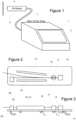
- Figure 1 shows an electrostatic deflection type continuous inkjet printer.
- the printer forms a continuous jet of ink and has an arrangement of electrodes for charging drops of ink and deflecting the drops electrostatically in order to print a desired pattern.
- the main fluid and electrical components are housed within a main printer body 1.
- An operator communicates with the printer via a touchscreen display 3.
- the ink jet is formed within a print head 5, which also includes the electrode arrangement for charging and deflecting the ink drops, and the print head 5 is connected to the main printer body 1 by a flexible connection 7 known as a conduit or an umbilical. Drops of ink, deflected as necessary to create the desired pattern, travel from the print head 5 and strike the surface 9 of an object conveyed past the print head 5, in order to print the desired pattern on the surface 9 of the object.
- Figure 2 is a schematic top view and Figure 3 is a schematic side view of the main components of the print head 5.
- Pressurised ink delivered from the main printer body 1 through the umbilical 7, is provided via an ink feed line 11 to an ink gun 13.
- the pressurised ink leaves the ink gun 13 through a small jet-forming orifice to form an ink jet 15.
- the ink jet 15 is formed continuously. Accordingly, this type of ink jet printer is known as a continuous ink jet printer, by contrast with a drop-on-demand printer in which a drop of ink is ejected only when a dot is to be printed.
- the ink jet 15 leaves the ink gun 13 as a continuous unbroken stream of ink, it rapidly breaks into separate drops.
- the path of the inkjet passes through a slot in a charge electrode 17, which is positioned so that the ink jet 15 separates into drops while it is in the slot through the charge electrode 17.
- the ink is electrically conductive and the ink gun 13 is held at a constant voltage (typically ground). Accordingly, any voltage applied to the charge electrode 17 induces a charge into the part of the ink jet 15 that is in the slot of the charge electrode 17. As the ink jet 15 separates into drops, any such charge is trapped on the drops. Accordingly, the amount of charge trapped on each drop can be controlled by changing the voltage on the charge electrode 17.
- the ink jet 15 then passes between two deflection electrodes 19, 21.
- a large potential difference typically several kilovolts
- the drops of ink are deflected by the electric field and the amount of deflection depends on the amount of charge trapped on each drop. In this way, each ink drop can be steered into a selected path.
- uncharged ink drops which pass through the electric field without deflection, travel to a gutter 23 where they are caught. Suction is applied to the inside of the gutter 23 by a suction line 25, and so the ink received by the gutter 23 is sucked away and returned through the umbilical 7 to the main printer body 1, for reuse.
- FIG 4 is a simplified schematic diagram of a fluid system for the ink jet printer of Figure 1 .
- Ink is held in an ink feed tank 27 in the main printer body 1.
- the interior of the ink feed tank 27 is held at atmospheric pressure by a vent 29.
- Ink is sucked out of the ink feed tank 27 by a pump 31, via a filter 33.
- the ink, pressurised by the pump 31, flows through a first Venturi 35 and back to the ink feed tank 27. Ink will flow continuously around this loop as long as the pump 31 is running.
- the flow of ink through the first Venturi 35 generates suction.
- a pressure transducer (pressure sensor) 37 is used to sense the ink pressure on the outlet side of the ink pump 31.
- the ink feed line 11 is also connected to the outlet side of the ink pump 31 and receives pressurised ink.
- a main ink feed valve 39 in the main printer body 1 controls the flow of ink to the print head 5 through the ink feed line 11.
- the gutter suction line 25 returns ink from the gutter 23 through the umbilical 7 to the main printer body 1, and receives suction from the first Venturi 35. Fluid flow in the gutter suction line 25 is controlled by a gutter valve 41.
- the first Venturi 35 also provides suction to a purge line 43, which passes through the umbilical 7 to the print head 5 in order to apply suction to the interior of the ink gun 13 when required. Flow in the purge line 43 is controlled by a purge valve 45.
- the solvent in the ink used to form the ink jet 15 tends to evaporate, causing a change in the viscosity of the ink.
- Spare solvent is held in a solvent reservoir 47 which receives suction from a second Venturi 49 through a solvent top-up line 51.
- the second Venturi 49 is preferably provided in parallel with the first Venturi 35, as shown in Figure 4 .
- a solvent top-up valve 53 in a solvent top-up line 51 is opened briefly, allowing the second Venturi 49 to suck a small quantity of solvent from the solvent reservoir 47. Solvent sucked in by the second Venturi 49 joins the ink flow through the Venturi and therefore passes into the ink feed tank 27, so as to dilute the ink in the ink feed tank.
- the ink jet printer As the ink jet printer prints, it will slowly use up ink from the ink feed tank 27.
- the ink feed tank 27 is topped up from an ink reservoir 55.
- Ink is sucked out of the ink reservoir 55 by the second Venturi 49 via an ink top-up line 57, controlled by an ink top-up valve 59, in a similar manner to the operation for topping up with solvent from the solvent reservoir 47.
- the solvent reservoir 47 and the ink reservoir 55 are respectively supplied from a solvent container 61 in the form of a removable bottle or cartridge and an ink container 63 in the form of a removable bottle or cartridge, and the operator replaces the cartridges 61, 63 as necessary.
- the solvent reservoir 47 and the ink reservoir 55 are sealed, and the solvent cartridge 61 and the ink cartridge 63 are fitted to the respective reservoirs 47, 55 with liquid-tight seals.
- This has the consequence that, when the second Venturi 49 sucks ink or solvent from the respective reservoirs 47, 55, there is no path for air to flow into the reservoirs 47, 55 or the solvent or ink container 61, 63 to replace the volume of liquid that has been withdrawn. Consequently, the ink and solvent containers 61, 63 are provided as deformable cartridges which will collapse as liquid is sucked out of them.
- the second Venturi 49 develops sufficient suction to overcome any stiffness in the material of the cartridges 61, 63 and is therefore able to suck ink and solvent from the reservoirs 47, 55 while forcing the ink and solvent containers 61, 63 to deform.
- Figure 5 shows schematically some of the components inside the main body 1 of the printer.
- the printer has a main body ink system 65, which includes the components in Figure 4 that are shown inside the main printer body 1.
- the main body ink system 65 and other parts of the printer operate under the control of a control system 67.
- the control system 67 for example, sends drive currents to the ink pump 31 and to the various valves, 39, 41, 45, 53, 59 of the main body ink system 65.
- the control system 67 receives outputs from the pressure sensor 37 and also from level sensors in the ink feed tank 27, the solvent reservoir 47 and the ink reservoir 55.
- the control system 67 also provides outputs to, and receives inputs from, the touchscreen display 3.
- Fluid lines 69 connect the main body ink system 65 to the print head 5 through the umbilical 7. These fluid lines will include the ink feed line 11, the gutter suction line 25 and the purge line 43 shown in Figure 4 .
- Electrical lines 71 connect the control system 67 to the print head 5 via the umbilical 7. These electrical lines will include lines for applying the appropriate voltages to the charge electrode 17 and the deflection of electrodes 19, 21, and a drive signal to a piezoelectric crystal inside the ink gun 13 that applies a vibration to the ink that forms the ink jet 15 in order to control the manner in which it breaks into drops.
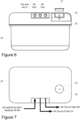
- Figure 6 shows a side view of the ink feed tank 27 and Figure 7 shows a top view of it.
- the ink feed tank 27 is removable, and will be replaced from time to time during operation of the printer. This ensures that the filter 33 does not become clogged by the accumulation of dust or other particles in the ink that may enter the ink feed tank, for example via the gutter 23, during extended operation of the printer.
- a fresh ink feed tank 27 is fitted into the printer it contains no ink. Even if the ink feed tank 27 is not removable, it may be necessary to drain it from time to time in order to remove degraded ink and to replace the ink filter 33, and after this operation the ink tank will contain no ink.
- the second Venturi 49 is not able to suck ink out of the ink reservoir 55 and ink cartridge 63 in order to provide an initial charge of ink to the ink feed tank 27, because the second Venturi 49 cannot develop suction unless ink is flowing through it, and the ink pump 31 is unable to provide a supply of ink to the Venturis 35, 49 until there is some ink in the ink feed tank 27.
- the ink feed tank 27 is provided with a fitting (shown in more detail in Figure 8 ) to enable an ink cartridge 63 to be connected directly to the ink feed tank 27, allowing ink to be transferred from the ink cartridge 63 into the ink feed tank 27. Because the printer is not able to provide any suction in this state, for sucking ink out of the ink cartridge, the operator transfers the ink manually. Since the ink cartridge 63 is deformable (as discussed above with reference to the operation of the second Venturi 49), the operator can simply squeeze the ink cartridge in order to force some ink out of it into the ink feed tank 27.
- Figure 9 shows the ink feed tank 27 in the main printer body 1, with an ink cartridge 63 connected to the top of the ink feed tank for adding an initial supply of ink to the ink feed tank 27.
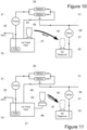
- Figure 10 shows a part of the fluid system of Figure 4 , showing the ink cartridge 63 in its position connected to the ink feed tank 27 for adding an initial supply of ink to the ink feed tank 27.
- the fitting for the ink cartridge 63 comprises a recess 73 provided in the top of the ink feed tank 27, for receiving the mouth of the ink cartridge 63.
- a hollow needle 75 sticks up from the floor of the recess 73, in order to pierce the seal across the mouth of the ink cartridge 63.
- the recess 73 is provided in the top of the ink feed tank 27, and the hollow needle 75 extends only a short distance down into the ink feed tank 27, the lower end of the hollow needle 75 remains in the air, and is not enclosed by the ink that collects in the ink feed tank 27. Accordingly, when the operator releases the ink cartridge 63 and it returns to its normal shape, the ink cartridge 63 sucks in air through the hollow needle 75 rather than sucking ink back in. Consequently, the operator can squeeze the ink cartridge 63 repeatedly to keep adding doses of ink to the ink feed tank 27 until a sufficient amount has been added to enable the ink pump 31 to withdraw ink from the ink feed tank 27 and drive it through the Venturis 35, 49.
- an initial supply of ink is provided to the ink feed tank 27, which primes the ink circuit (comprising the ink feed tank 27, the ink pump 31, the first Venturi 35 and the second Venturi 49) enabling the Venturis 35, 49 to create suction.
- the operator can remove the ink cartridge 63 from the recess 73.
- the ink cartridge 63 can then be moved, as shown by the arrow in Figure 10 , to its normal position mounted on the ink reservoir 55 (as shown in broken lines in Figures 9 and 10 ).
- a lid 77 is fitted on the recess 73 in order to cover the sharp end of hollow needle 75 for safety and also to prevent dust and dirt from entering the ink feed tank 27 through the hollow needle 75.
- FIG 8 shows the recess 73, the hollow needle 75 and the mouth of the ink cartridge 63 in more detail.
- the ink cartridge 63 has a neck portion 79 that is shaped to cooperate with the fitting on the ink reservoir 55 that holds the ink cartridge 63 with a liquid-tight seal.
- the operator fits an adapter 81 around the neck portion 79 of the ink cartridge 63. The operator then inserts the neck portion 79 of the ink cartridge 63, together with the adapter 81, into the recess 73 and presses the ink cartridge 63 down until the end of the adapter 81 contacts the bottom of the recess 73. In this position, the hollow needle 75 pierces the seal 83 across the mouth of the ink container 63, as shown in Figure 8 .
- the seal 83 across the mouth of the ink cartridge 63 is a re-sealable septum
- the hollow needle 75 is a suitable septum spike, so that the septum seals the hole created by the hollow needle 75 as the ink cartridge 63 is withdrawn from the recess 73, with the result that any ink remaining in the ink cartridge 63 does not spill out.
- the main printer body has a lid 85 that can be opened to allow replacement of the ink cartridge 63, the solvent cartridge 61 and the ink feed tank 27.
- the ink cartridge 63 When the ink cartridge 63 is received in the fitting in the top of the ink feed tank 27, it extends upwardly out of the main printer body 1 and the operator can easily grasp the sides of the ink cartridge 63 to squeeze it.
- the ink cartridge When the ink cartridge is fitted to the ink reservoir 55, as shown in broken lines in Figure 9 , it is fully inside the main printer body 1 and the lid 85 can be closed.
- the printer can guide the operator through this procedure via the touchscreen display 3.
- the touchscreen display 3 may initially display instructions telling the operator to fit the adapter 81 to the neck portion 79 of the ink cartridge 63, and then to fit the ink cartridge 63 into the recess 73.
- the printer can operate the ink pump 31 and monitor the pressure detected by the pressure transducer 37. While the ink feed tank 27 is empty and the ink pump 31 is pumping air, the pressure detected by the pressure transducer 37 will be lower than the normal ink pressure during operation of the printer. Once the ink pump 31 begins to withdraw ink from the ink feed tank 27, the pressure detected by the pressure transducer 37 will increase.
- the system may wait until a pre-set minimum pressure is detected by the pressure transducer 37 while the ink pump 31 is running at a first speed, selected to ensure that the ink pump 31 is not damaged by pumping air.
- a pre-set minimum pressure is detected by the pressure transducer 37 while the ink pump 31 is running at a first speed, selected to ensure that the ink pump 31 is not damaged by pumping air.
- the ink pump 31 can be set to run at a second speed designed to pressurise the ink, and the ink pressure detected by the pressure transducer 37 is monitored by the control system 67 until a further pre-set pressure is detected that indicates that ink is flowing through the ink pump 31 and the first and second Venturis 35, 49 satisfactorily.
- control system 67 can use the touchscreen display 3 to instruct the operator to stop adding further ink from the ink cartridge 63 to the ink feed tank 27 and can provide instructions telling the operator how to withdraw the ink cartridge from the recess 73 and how to fit it into the ink reservoir 55.
- the fitting for connecting the ink cartridge 63 to the ink tank can take other forms.
- the recess 73 may be absent and the hollow needle 75 may extend upwardly from the surface of the ink feed tank 27.
- FIG. 11 An alternative arrangement is shown in Figure 11 .
- the fitting for the ink cartridge i.e. the recess 73 and the hollow needle 75
- the priming connector 87 is connected to the ink feed tank 27 by a priming line 89.
- the priming line 89 is shown in Figure 11 as connecting to the ink feed tank 27 at its side.
- the priming line 89 may alternatively connect to the ink feed tank 27 at its top, or may even connect at the bottom of the ink feed tank 27 and extend upwardly within the ink feed tank 27.
- the end of the priming line 89 remote from the priming connector 87 should be sufficiently high up in the ink feed tank 27 that when the operator releases the ink cartridge after squeezing it, expansion of the ink cartridge 63 sucks in air from the interior of the ink feed tank 27 rather than sucking ink back in.
- Figure 12 shows an alternative arrangement in which the priming line 89 joins the ink circuit at the fluid flow line between the output of the Venturis 35, 49 and the input to the ink feed tank 27.
- the priming line 89 joins the ink circuit at the fluid flow line between the output of the Venturis 35, 49 and the input to the ink feed tank 27.
- the ink pump 31 will be operating (although possibly at a reduced speed compared with normal) during the priming operation.
- the ink pump 31 is a gear pump and its pumping ability will be reduced until it is wetted with ink. Nevertheless, it will cause some air flow through the Venturis 35, 49 and into the ink feed tank 27.
- the gutter valve 41, the purge valve 45, the solvent top-up valve 53 and the ink top-up valve 59 connected to the suction inlets of the first and second Venturis 35, 49 will all be closed during the priming operation so that air cannot escape through the Venturis.
- the vent 29 ensures that the air pressure in the ink feed tank 27 remains close to atmospheric pressure and does not provide a substantial resistance to flow into and out of the ink feed tank 27. Consequently, when ink is squeezed out of the ink cartridge 63 during priming with the arrangement of Figure 12 , there is little or no tendency for the ink to flow towards the Venturis 35, 49 and it will flow reliably into the ink feed tank 27.
- the priming line 89 can be connected elsewhere in the ink circuit. Preferably it is connected at a place between the outlet of the Venturis 35, 49 and the inlet of the ink pump 31, and accordingly in Figure 13 it is shown connected in the line between the outlet of the ink feed tank 27 and inlet of the ink pump 31.
- the ink pump 31 and the ink feed tank 27 are arranged so that even when the ink pump 31 is not wet with ink, it is capable of withdrawing ink from the ink feed tank 27 into the ink pump 31 so that the ink pump 31 can pump the ink around the ink circuit once the ink feed tank 27 is primed with ink.
- ink from the ink cartridge 63 flows through the priming line 89 into the line between the ink feed tank 27 and inlet of the ink pump 31, and it will then flow into the ink pump 31 in the same way as any ink that the ink pump 31 withdraws from the ink feed tank 27.
- the ink will wet the ink pump 31, improving its pumping ability.
- the ink will then be pumped through the first and second Venturis 35, 49 and into the ink feed tank 27.
- the ink pump 31 is running and is capable of ensuring that any ink flows into its inlet, air will flow from the ink feed tank 27 into the priming line 89 and the ink cartridge 63 when the operator releases the ink cartridge 63 and it expands, and ink will not be pulled back from the inlet of the pump 31.
- the ink pump 31 pumps ink as soon as the operator begins to transfer ink from the ink cartridge 63 into the ink circuit by squeezing the ink cartridge 63. Therefore the pressure at the outlet side of the pump 31 may be a less reliable way of detecting when sufficient ink has been fed into the ink feed tank 27 as compared with arrangements in which the ink flows from the ink cartridge 63 into the ink feed tank 27 without going via the ink pump 31. Accordingly, with the arrangement of Figure 13 it is preferred that the control system 67 determines when sufficient ink has been transferred to the ink feed tank 27 to prime the ink circuit by monitoring the ink level in the ink feed tank 27 rather than by monitoring the ink pump outlet pressure using the pressure transducer 37.
- the priming line 89 to the ink circuit at a position between the outlet of the ink pump 31 and the inlets of the Venturis 35, 49. This part of the ink circuit is exposed to the full outlet pressure of the ink pump 31. While the pump 31 merely pumps air, the pressure at this part of the ink circuit is moderate, and the air flow will drive the ink, squeezed out of the ink cartridge 63, around the ink circuit and into the ink feed tank 27. However, as the amount of ink in the ink feed tank increases and ink begins to be sucked from the ink feed tank 27 into the ink pump 31, the outlet pressure of the ink pump 31 may increase.
- the ink container 63 may be exposed to unacceptable pressures if the priming line 89 is connected to this part of the ink circuit.
- a lid 77 is used to close the recess 73 in the priming connector 87 in the arrangements of Figures 11 to 13 , in the same way as in the arrangement of Figures 6 to 10 .
- the hollow needle 75 in the recess 73 connects to a point in the ink feed tank 27 that is held substantially at atmospheric pressure by the vent 29, and therefore the lid 77 is provided only for safety and to keep out dirt and dust and it does not need to be airtight.
- the hollow needle 75 is connected through the priming line 89 to a point in the ink circuit which may not always be at atmospheric pressure and therefore the lid 77 preferably provides an airtight seal to prevent flow along the priming line 89 when the ink cartridge 63 is not present. It is particularly important to prevent flow along the priming line 89 during normal operation of the printer in the case of the arrangement of Figure 13 , since otherwise there is a danger that air could be sucked into the ink pump 31 through the priming line 87, mixing air bubbles into the ink that is ultimately supplied to the ink gun 13. This is undesirable because it would disrupt the ink jet 15. Additionally, it may be difficult to keep the ink pressure at the correct level. Accordingly, it may be desirable to provide an optional priming shut off valve 91 in the priming line 89, as shown in broken lines in Figure 13 .
- the outlet pressure of the ink pump 31 provides the pressure that drives the ink jet 15 out of the ink gun 13. Therefore if the priming line 89 is connected to the ink circuit between the outlet side of the ink pump 31 and the inlet side of the Venturis 35, 49, it is particularly important to provide a liquid-tight seal for the lid 77 when the ink cartridge 63 is removed, or to provide the priming shut-off valve 91 in the priming line 89, in order to prevent ink from being forced out of the ink circuit at high pressure via the priming line 89 during normal operation of the printer.
- the ink cartridge 63 is moved from its position for priming the ink circuit to its position for allowing ink top-up via the second Venturi 49, as shown by the bold arrow in Figures 10 to 13 .
- Figure 14 shows a modification of the arrangement to Figure 11 in which only a single position for the ink cartridge 63 is required.
- the priming connector 87 is connected both to the priming line 89 and to the ink top-up line 57. Accordingly, the ink cartridge 63 can remain in the priming connector 87 throughout normal operation of the printer, and the ink top-up valve 59 is opened in order to suck ink from the ink cartridge 63 through the second Venturi 49 and into the ink feed tank 27 whenever the level of ink in the ink feed tank 27 is too low.
- the ink top-up valve 59 is closed, to ensure that ink flows along the priming line 89 when the ink cartridge 63 is squeezed.
- a priming shut off valve 91 is provided in the priming line 89.
- This valve is open during the priming operation, to allow ink to flow from the ink cartridge 63 along the priming line 89 and into the ink feed tank 27.
- the priming shut off valve 91 is closed during ink top-up operation, in order to ensure that suction from the second Venturi 49 is not applied to the interior of the ink feed tank 27 via the priming line 89.
- Figure 15 shows a modified arrangement based on the arrangement of Figure 12 , in which the ink cartridge 63 does not need to be moved and the priming line 89 joins the line from the Venturis 35, 49 to the ink feed tank 27.
- Figure 16 shows a modification to the arrangement of Figure 13 in which the priming connector 87 is connected to the ink top-up line 57 as well as to the priming line 89, and the priming line 89 joins the ink circuit between the ink tank 27 and the ink pump 31.
- FIG. 17 An example of such an arrangement is show in Figure 17 .
- the ink system layout in Figure 4 and Figures 10 to 17 is purely schematic and does not indicate the physical locations of components.
- the ink reservoir 55 is positioned above the ink feed tank 27 so that ink can flow from the ink reservoir 55 to the ink feed tank 27 under the influence of gravity when the priming shut off valve 91 is open.
- the priming shut off valve remains necessary, both to prevent unwanted flow from the ink reservoir 55 into the ink feed tank 27 during normal operation and to protect the ink feed tank 27 from suction during an ink top-up operation.
- the ability to transfer ink from the ink cartridge 63 by squeezing or compressing the ink cartridge 63 during a priming operation has the result that the ink circuit can be primed with ink without the need to provide a diaphragm pump or other pump that can operate without priming.
- the ink pump 31 can pump ink through the Venturis 35, 49 and these can develop sufficient suction to withdraw further ink from the ink cartridge 63, both to fill the ink feed tank 27 to its normal operating level when the printer is commissioned following replacement of the ink feed tank 27, and during an ink top-up operation.
- the diaphragm pump (or other pump that can function without priming) is not needed at all during operation of the printer and can be omitted, with a consequent saving of cost and space inside the main printer body 1.
- Figures 14 to 17 may be more convenient for the operator because the ink container 63 does not need to be moved from a priming position to a top-up position.
- these designs require that it is possible to squeeze or otherwise compress the ink container 63 when it is in the position it will have during normal operation of the printer. If it is desired that the ink container is enclosed within the main printer body 1 during operation of the printer, this may require the main printer body to be designed with space around the position of the ink container 63 to allow access for squeezing or compression. As a result, the main printer body 1 may be larger than would otherwise be necessary.
- the ink cartridge may be partially outside the main printer body 1 when it is in its priming position, allowing easy access for squeezing the ink cartridge 63 (as shown in unbroken lines in Figure 9 ).
- the ink cartridge 63 is then moved, after the priming operation, to its top-up position.
- the top-up position can be wholly enclosed within the main printer body 1 (as shown in broken lines in Figure 9 ) without the need to provide space for access to allow squeezing, enabling the printer to be more compact.
Landscapes
- Chemical & Material Sciences (AREA)
- Life Sciences & Earth Sciences (AREA)
- Engineering & Computer Science (AREA)
- Materials Engineering (AREA)
- Wood Science & Technology (AREA)
- Organic Chemistry (AREA)
- Ink Jet (AREA)
Description
- The present invention relates to a continuous ink jet printer, for example an electrostatic deflection type continuous ink jet printer.
- In the operation of a continuous ink jet printer, a continuous jet of ink drops is formed. Usually, the drops are deflected in flight so that only some drops are used for printing. Drops of ink that are not required for printing are caught by a gutter and are returned to an ink tank within the main body of the printer. In an electrostatic deflection ink jet printer, this deflection is performed by trapping electric charges on some or all of the drops of ink, and using an electrostatic field to deflect the charged drops so that the printer prints the desired printed pattern. The ink includes a solvent which is normally highly volatile so that the drops of ink dry quickly after printing. The solvent also tends to evaporate from the ink that is caught in the gutter and returned to the ink tank, so that the ink used by the printer loses solvent over time. In order to maintain the correct ink viscosity, additional solvent is added from time to time. Additionally, the ink is slowly used up as the printer prints and therefore the ink in the ink tank needs to be replenished.
- In order to stop and start the ink jet, and perform other operations such as adding ink and solvent, sucking air into the ink gun used to form the ink jet, and to apply or withdraw suction from the gutter, various valves are required within the ink system. The ink system will also normally include other electrical components, such as an ink pump for pressurising the ink and a pressure sensor for sensing the ink pressure. The suction for the gutter, and for applying suction to the interior of the ink gun if necessary, is often provided by a Venturi device which generates suction from the flow of ink through it. The ink is pumped through the Venturi by the ink pump, and the ink that flows through the Venturi is returned to the ink tank.
- In order to add solvent to the ink in the ink tank from time to time, it is possible to provide a supply of solvent in a solvent tank and to use the Venturi device to suck a small amount of solvent from the solvent tank into the ink that flows through the Venturi and is returned to the ink tank, as shown for example in
CN 205044308 U . When the solvent tank gets low it can be topped up by the operator. In a similar way, the ink in the ink tank can be topped up by the operator as necessary. However, owing to the possibility of spills it is preferred to fit a removable solvent container such as a bottle or cartridge into the machine, and similarly to fit a removable ink container, such as a bottle or cartridge into the machine, and arrange for the printer to withdraw solvent and ink from the containers as necessary. The containers are replaced by the operator when they are empty. The likelihood of substantial spills of ink or solvent is reduced because the operator should only be handling the removable containers either when they are full and sealed or when they are empty. The ink and solvent containers can be arranged to supply ink and solvent reservoirs, from which the printer sucks ink and solvent as required, as shown for example inEP2588323 or the ink and solvent can be sucked directly from the containers. - It is known to hold the ink and solvent containers in the printer with a substantially liquid-tight seal, so as to minimise the possibility of spillage from the containers especially if the printer is tilted or jolted as it is carried from one place to another. However, systems in which the ink and solvent containers are sealed into the ink system of the printer typically have the effect that ink and solvent must be sucked out of the containers without the possibility of air entering the containers to replace the volume of liquid that is removed. Consequently, the containers have to deform so that their internal volumes reduce as liquid is removed. Therefore the suction applied to remove ink and solvent from the containers must be sufficient to overcome the containers' resistance to deformation. In practice, the suction provided by a Venturi is usually adequate for this purpose and it is known to suck solvent from a sealed reservoir and/or container using a Venturi. However, the Venturi only generates suction when ink is flowing through it. This means that the Venturi cannot be used to suck liquid from a container when the printer is initially being commissioned or at any other time when there is little or no ink in the ink tank, because the ink pump cannot pump ink through the Venturi to generate suction under these circumstances. Therefore, it is known to suck ink out of the ink container using a diaphragm pump, which has the advantage that it can develop adequate suction to remove ink from the ink container without needing already to contain ink in order to operate.
- Aspects and embodiments of the present invention provide systems in which an arrangement is made enabling an initial charge of ink to be added to the ink tank or supplied to the ink pump, thereby enabling ink to be pumped through a device for developing suction (e.g. a Venturi), which can then develop sufficient suction to suck ink from an ink container in subsequent operation of the printer. In this way, the need to provide a diaphragm pump to suck ink from the ink container is avoided. This can save cost and space in the printer.
- As set out in
claim 1, the main embodiment of the present invention provides a continuous ink jet printer comprising an ink tank, an ink pump and at least one suction device, the ink tank, the ink pump and the at least one suction device being provided in an ink circuit in which the ink pump can pump ink from the ink tank through the ink pump to an inlet of the at least one suction device, through the at least one suction device and then back to the ink tank, the at least suction device further comprising at least one suction inlet, and the at least one suction device being arranged to create suction from the flow of ink through it, the printer further comprising: an ink feed line connected to the outlet side of the ink pump to receive pressurised ink therefrom and supply it to an ink gun of a print head; a gutter line connected to a suction inlet of the at least one suction device to allow ink to be sucked away from a gutter of the print head; an ink top-up line connected to a suction inlet of the at least one suction device to allow ink to be sucked into the ink circuit, and a solvent (diluent) top-up line connected to a suction inlet of the at least one suction device to allow solvent (diluent) to be sucked into the ink circuit, characterised in that the printer further comprises a first fitting for connecting an ink container to the ink circuit at the ink tank or at a location in the ink circuit that is (a) between an outlet of the at least one suction device and an inlet of the ink tank or (b) between an outlet of the ink tank and an inlet of the ink pump or (c) between an outlet of the ink pump and an inlet of the at least one suction device. - As set out in claim 10, the main embodiment of the present invention provides a method of priming an ink circuit in a continuous ink jet printer, wherein the ink circuit comprises an ink tank, an ink pump and at least one suction device that creates suction from the flow of ink through it, the at least one suction device having an inlet for receiving ink through it form the ink circuit and further comprising at least one suction inlet, and wherein the printer further comprises: an ink feed line connected to the outlet side of the ink pump to receive pressurised ink therefrom and supply it to an ink gun of a print head; a gutter line connected to a suction inlet of the at least one suction device to allow ink to be sucked away from a gutter of the print head; an ink top-up line connected to a suction inlet of the at least one suction device to allow ink to be sucked into the ink circuit, and a solvent (diluent) top-up line connected to a suction inlet of the at least one suction device to allow solvent (diluent) to be sucked into the ink circuit, characterised in that the printer further comprises a first fitting for connecting an ink container to the ink circuit at the ink tank or at a location in the ink circuit between an outlet of the at least one suction device and an inlet of the ink tank or at a location in the ink circuit between an outlet of the ink tank and an inlet of the ink pump or at a location in the ink circuit between an outlet of the ink pump and an inlet of the at least comprises positioning an ink container on the first fitting and compressing it to force ink from the ink container through the first fitting into the ink circuit.
- Optional features are set out in the remaining claims.
- In an embodiment of the invention a continuous ink jet printer has an ink circuit comprising an ink tank, an ink pump and a suction device that generates suction from a flow of liquid through it, such as a Venturi. The suction device is used to suck in extra solvent or ink as required. However, if the ink tank is empty, no ink can be pumped through the suction device and so it will not develop suction. Therefore the suction device cannot be used to suck in an initial supply of ink to an empty tank. This problem is overcome by connecting a removable ink container to the ink tank or elsewhere in the ink circuit, preferably between the outlet of the suction device and the inlet to the pump, and then compressing the ink container manually to force ink into the ink circuit. When enough ink has been added, the pump will drive ink through the suction device and suction will be generated.
- In an embodiment of the present invention there is provided a continuous ink jet printer having an ink tank, an ink pump and a suction device (such as a Venturi) that develops suction from the flow of ink through it, arranged in an ink flow circuit such that ink is withdrawn from the ink tank by the ink pump, and is pumped by the ink pump through the suction device and back to the ink tank. The printer has a first fitting to allow a removable ink container to be connected for supply of ink to the ink flow circuit at a supply position. Additionally, either (a) the first fitting is also connected, via a first valve, to a suction inlet of the suction device and the printer has a second valve to selectively block or permit flow of fluid between the fitting and the supply position, the flow from the fitting to the supply position not being via the first valve or (b) the printer has a second fitting connected via a first valve to a suction inlet of the suction device, the second fitting allowing a removable ink container to be connected for supply of ink to the suction inlet of the suction device. Preferably the supply position is downstream of the outlet of the suction device and upstream of the inlet of the ink pump, and is most preferably at the ink tank.
- Preferably, the fitting that allows ink to be added to the ink flow circuit at the supply position (the first fitting) is arranged to make a liquid-tight seal with an ink container, in order to minimise the risk of spillage. In order to transfer ink from the container into the ink flow circuit, the ink container may have flexible walls (which will typically be the case for an ink container to be used with a printer that sucks ink from the container while the container is held in a fitting with a liquid-tight seal), and the operator can squeeze the container in order to force some ink out of it.
- It may be that the amount of ink initially in an ink container is different from the amount of ink to be transferred from the ink container into the ink flow circuit in order to enable sufficient flow through the suction device to develop suction. In this case, if the printer has a first fitting for supply of ink to the supply position and a second fitting for supply of ink to the suction inlet of the suction device, the operator may wish to remove the ink container from the first fitting while it still has some ink in it, in order to transfer the ink container to the second fitting. Accordingly, the first fitting may have a hollow spike suitable for piercing a re-sealable septum, and the ink container may have a re-sealable septum to be pierced by the hollow spike when the container is fitted to the fitting. Ink can then be transferred from the container through the hollow spike, for example by squeezing the container as mentioned above. When the container is removed, the re-sealable septum seals the hole made by the hollow spike, allowing the container to be removed without substantial spillage of ink.
- An embodiment of the present invention provides a method of priming an ink flow circuit in a continuous ink jet printer, the ink flow circuit comprising an ink tank, an ink pump and a suction device that develops suction when ink is pumped through it and the printer having a connection for supply of ink to a suction inlet of the suction device, the method comprising adding ink manually from an ink container to a point in the ink flow circuit until there is sufficient ink in the ink tank for the ink pump to be able to withdraw ink from it and pump ink through the suction device. Preferably the point in the ink flow circuit, at which ink is added, is between the outlet of the suction device and the inlet of the ink pump, and most preferably it is at the ink tank.
- Normally the interior of the ink tank is held close to atmospheric pressure by a vent. Therefore there is no significant pressure difference between the air outside the first fitting and the supply position in the ink flow circuit if the supply position is at the ink tank. If the supply position is between the suction device outlet and the ink tank, the pressure at the supply position will tend to be slightly above atmospheric pressure. If the supply position is between the ink tank outlet and the ink pump inlet, the pressure at the supply position will tend to be below atmospheric pressure. If the supply position is between the ink pump outlet and the suction device inlet, supply of ink may be possible if the ink pump is run backwards during the ink supply operation, so that the supply position is at a slight negative pressure and the ink flows from the supply position through the ink pump to the ink tank. However, in this case the supply position will normally be pressurised by the operation of the pump so as to be significantly above atmospheric pressure and at substantially the same pressure as the ink inside the ink gun that forms the ink jet. Therefore if the supply position is not at the ink tank, and the first fitting is not also connected to a suction inlet of the suction device but there is a second fitting connected to the suction inlet of the suction device so that the operator may wish to transfer an ink container from the first fitting to the second fitting, it may be useful to provide a sealing cap for the first fitting or possibly a valve between the first fitting and the supply position, in order to protect the ink circuit from exposure to atmospheric pressure at the supply position when the ink container is absent. Otherwise ink may tend to flow out through the first fitting or air may be sucked in owing to the pressure difference.
- Preferably the printer also has a further fitting to allow a supply of solvent or diluent to be connected to a suction inlet of a suction device in the ink flow circuit. Preferably the further fitting is connected to a suction inlet of the same suction device as the first or second fitting is connected to, for the supply of ink. The further fitting may be connected to the same or a different suction inlet as the fitting for supply of ink.
- The printer usually comprises means for deflecting the ink drops in flight, so that different drops can travel to different destinations. Typically, the ink is electrically conductive when wet, and the printer comprises an arrangement of electrodes to trap electric charges on the ink drops and create electrostatic fields in order to deflect the charged drops. This arrangement may include a charge electrode for trapping charges on the ink drops and deflection electrodes for creating an electric field that deflects the drops according to the level of trapped charge.
- Normally the print head of the ink jet printer is separate from the main printer body and is connected to the main printer body by a flexible connector sometimes known as a conduit or umbilical that carries fluid and electrical connections between the print head and the main printer body. The print head typically includes an ink gun that receives pressurised ink and allows it to exit through an orifice to form a jet of ink, a charge electrode for trapping electric charges on drops of ink, deflection electrodes for creating an electrostatic field for deflecting charged drops of ink, and a gutter for collecting drops of ink that are not used for printing. The umbilical will include fluid lines for providing pressurised ink to the ink gun and for applying suction to the gutter and transporting ink from the gutter back to the main printer body. Often it will include other fluid lines such as a purge line allowing suction to be applied to the ink gun if required to suck air in through the jet-forming orifice to remove a blockage or to empty the ink gun of ink, and a flush line for delivering solvent to the ink gun. Electrical connections may be provided, for example to drive a piezoelectric crystal or the like for imposing pressure vibrations on the ink jet in order to control the way in which the jet breaks into drops, electrical connections for the charge electrode and the deflection electrodes, and connections may also be provided for drive currents for any valves in the print head. Accordingly, the umbilical carries both electrical connections and fluid connections.
- Embodiments of the present invention, given by way of non-limiting example, will now be described with reference to the accompanying drawings.
-
Figure 1 shows an ink jet printer embodying the present invention. -
Figure 2 is a schematic top view of the print head of the printer ofFigure 1 . -
Figure 3 is a schematic side view of the print head of the printer ofFigure 1 . -
Figure 4 shows simplified schematic diagram of the ink system (fluid system) of the printer ofFigure 1 . -
Figure 5 shows the main components inside the main body of the printer ofFigure 1 . -
Figure 6 is a side view of the ink tank. -
Figure 7 is a top view of the ink tank. -
Figure 8 is a detailed view of the fitting for allowing ink to be added to the ink tank for priming. -
Figure 9 shows the ink tank in the main body of the printer, with an ink cartridge fitted to it from which to add ink to the ink tank for priming. -
Figure 10 is a schematic diagram of the main ink circuit from the ink system ofFigure 4 , with the ink cartridge fitted to the ink tank. -
Figure 11 is a schematic diagram of the main ink circuit from the ink system ofFigure 4 , with the ink cartridge fitted to a priming connector that is connected to the ink tank. -
Figure 12 is a schematic diagram of the main ink circuit from the ink system ofFigure 4 , with the ink cartridge fitted to a priming connector that is connected to the line from the Venturis to the ink tank. -
Figure 13 is a schematic diagram of the main ink circuit from the ink system ofFigure 4 , with the ink cartridge fitted to a priming connector that is connected to the line from the ink tank to the ink pump. -
Figure 14 is a modification ofFigure 11 , in which the priming connector is also connected to the suction inlet of a Venturi for ink top-up. -
Figure 15 is a modification ofFigure 12 , in which the priming connector is also connected to the suction inlet of a Venturi for ink top-up. -
Figure 16 is a modification ofFigure 13 , in which the priming connector is also connected to the suction inlet of a Venturi for ink top-up. -
Figure 17 is a schematic diagram of the main ink circuit from the ink system ofFigure 4 , with the ink cartridge fitted to the ink reservoir which is in turn connected to both the ink tank for priming and to the suction inlet of a Venturi for top-up. -
Figure 1 shows an electrostatic deflection type continuous inkjet printer. The printer forms a continuous jet of ink and has an arrangement of electrodes for charging drops of ink and deflecting the drops electrostatically in order to print a desired pattern. The main fluid and electrical components are housed within amain printer body 1. An operator communicates with the printer via atouchscreen display 3. The ink jet is formed within aprint head 5, which also includes the electrode arrangement for charging and deflecting the ink drops, and theprint head 5 is connected to themain printer body 1 by aflexible connection 7 known as a conduit or an umbilical. Drops of ink, deflected as necessary to create the desired pattern, travel from theprint head 5 and strike thesurface 9 of an object conveyed past theprint head 5, in order to print the desired pattern on thesurface 9 of the object. -
Figure 2 is a schematic top view andFigure 3 is a schematic side view of the main components of theprint head 5. Pressurised ink, delivered from themain printer body 1 through the umbilical 7, is provided via anink feed line 11 to anink gun 13. The pressurised ink leaves theink gun 13 through a small jet-forming orifice to form anink jet 15. Provided that pressurised ink is received by theink gun 13 and any valves in theink gun 13 are in the appropriate state, theink jet 15 is formed continuously. Accordingly, this type of ink jet printer is known as a continuous ink jet printer, by contrast with a drop-on-demand printer in which a drop of ink is ejected only when a dot is to be printed. - Although the
ink jet 15 leaves theink gun 13 as a continuous unbroken stream of ink, it rapidly breaks into separate drops. The path of the inkjet passes through a slot in acharge electrode 17, which is positioned so that theink jet 15 separates into drops while it is in the slot through thecharge electrode 17. The ink is electrically conductive and theink gun 13 is held at a constant voltage (typically ground). Accordingly, any voltage applied to thecharge electrode 17 induces a charge into the part of theink jet 15 that is in the slot of thecharge electrode 17. As theink jet 15 separates into drops, any such charge is trapped on the drops. Accordingly, the amount of charge trapped on each drop can be controlled by changing the voltage on thecharge electrode 17. - The
ink jet 15 then passes between twodeflection electrodes electrodes Figure 2 , uncharged ink drops, which pass through the electric field without deflection, travel to agutter 23 where they are caught. Suction is applied to the inside of thegutter 23 by asuction line 25, and so the ink received by thegutter 23 is sucked away and returned through the umbilical 7 to themain printer body 1, for reuse. - Drops of ink that are deflected by the field between the
deflection electrodes gutter 23, leave theprint head 5 and form printed dots on thesurface 9 of the object. -
Figure 4 is a simplified schematic diagram of a fluid system for the ink jet printer ofFigure 1 . Ink is held in anink feed tank 27 in themain printer body 1. The interior of theink feed tank 27 is held at atmospheric pressure by avent 29. Ink is sucked out of theink feed tank 27 by apump 31, via afilter 33. The ink, pressurised by thepump 31, flows through afirst Venturi 35 and back to theink feed tank 27. Ink will flow continuously around this loop as long as thepump 31 is running. The flow of ink through thefirst Venturi 35 generates suction. A pressure transducer (pressure sensor) 37 is used to sense the ink pressure on the outlet side of theink pump 31. - The
ink feed line 11 is also connected to the outlet side of theink pump 31 and receives pressurised ink. A mainink feed valve 39 in themain printer body 1 controls the flow of ink to theprint head 5 through theink feed line 11. Thegutter suction line 25 returns ink from thegutter 23 through the umbilical 7 to themain printer body 1, and receives suction from thefirst Venturi 35. Fluid flow in thegutter suction line 25 is controlled by agutter valve 41. Thefirst Venturi 35 also provides suction to apurge line 43, which passes through the umbilical 7 to theprint head 5 in order to apply suction to the interior of theink gun 13 when required. Flow in thepurge line 43 is controlled by apurge valve 45. - During operation of the printer, the solvent in the ink used to form the
ink jet 15 tends to evaporate, causing a change in the viscosity of the ink. In order to restore the ink to the correct viscosity, it is necessary to add further solvent from time to time. Spare solvent is held in asolvent reservoir 47 which receives suction from asecond Venturi 49 through a solvent top-up line 51. Thesecond Venturi 49 is preferably provided in parallel with thefirst Venturi 35, as shown inFigure 4 . In order to add solvent to the ink, a solvent top-upvalve 53 in a solvent top-up line 51 is opened briefly, allowing thesecond Venturi 49 to suck a small quantity of solvent from thesolvent reservoir 47. Solvent sucked in by thesecond Venturi 49 joins the ink flow through the Venturi and therefore passes into theink feed tank 27, so as to dilute the ink in the ink feed tank. - It is possible to provide suction to the solvent top-
up line 51 from thefirst Venturi 35, but it is preferred to use a separate Venturi for top-up operations because these operations tend to have a different suction requirement (lower flow rate at greater suction) from thegutter suction line 25. - As the ink jet printer prints, it will slowly use up ink from the
ink feed tank 27. When the ink level becomes too low, theink feed tank 27 is topped up from anink reservoir 55. Ink is sucked out of theink reservoir 55 by thesecond Venturi 49 via an ink top-up line 57, controlled by an ink top-upvalve 59, in a similar manner to the operation for topping up with solvent from thesolvent reservoir 47. Thesolvent reservoir 47 and theink reservoir 55 are respectively supplied from asolvent container 61 in the form of a removable bottle or cartridge and anink container 63 in the form of a removable bottle or cartridge, and the operator replaces thecartridges - In order to minimise spillages, it is preferred that the
solvent reservoir 47 and theink reservoir 55 are sealed, and thesolvent cartridge 61 and theink cartridge 63 are fitted to therespective reservoirs second Venturi 49 sucks ink or solvent from therespective reservoirs reservoirs ink container solvent containers second Venturi 49 develops sufficient suction to overcome any stiffness in the material of thecartridges reservoirs solvent containers - In practice, it is not always necessary to provide the
solvent reservoir 47 and theink reservoir 55, and the respective top-uplines containers -
Figure 5 shows schematically some of the components inside themain body 1 of the printer. The printer has a mainbody ink system 65, which includes the components inFigure 4 that are shown inside themain printer body 1. The mainbody ink system 65 and other parts of the printer operate under the control of acontrol system 67. Thecontrol system 67, for example, sends drive currents to theink pump 31 and to the various valves, 39, 41, 45, 53, 59 of the mainbody ink system 65. Thecontrol system 67 receives outputs from thepressure sensor 37 and also from level sensors in theink feed tank 27, thesolvent reservoir 47 and theink reservoir 55. Thecontrol system 67 also provides outputs to, and receives inputs from, thetouchscreen display 3. -
Fluid lines 69 connect the mainbody ink system 65 to theprint head 5 through the umbilical 7. These fluid lines will include theink feed line 11, thegutter suction line 25 and thepurge line 43 shown inFigure 4 .Electrical lines 71 connect thecontrol system 67 to theprint head 5 via the umbilical 7. These electrical lines will include lines for applying the appropriate voltages to thecharge electrode 17 and the deflection ofelectrodes ink gun 13 that applies a vibration to the ink that forms theink jet 15 in order to control the manner in which it breaks into drops. -
Figure 6 shows a side view of theink feed tank 27 andFigure 7 shows a top view of it. In this embodiment, theink feed tank 27 is removable, and will be replaced from time to time during operation of the printer. This ensures that thefilter 33 does not become clogged by the accumulation of dust or other particles in the ink that may enter the ink feed tank, for example via thegutter 23, during extended operation of the printer. However, when a freshink feed tank 27 is fitted into the printer it contains no ink. Even if theink feed tank 27 is not removable, it may be necessary to drain it from time to time in order to remove degraded ink and to replace theink filter 33, and after this operation the ink tank will contain no ink. Therefore it is necessary to supply ink to theink feed tank 27 before the printer can begin operation. However, thesecond Venturi 49 is not able to suck ink out of theink reservoir 55 andink cartridge 63 in order to provide an initial charge of ink to theink feed tank 27, because thesecond Venturi 49 cannot develop suction unless ink is flowing through it, and theink pump 31 is unable to provide a supply of ink to theVenturis ink feed tank 27. Accordingly, theink feed tank 27 is provided with a fitting (shown in more detail inFigure 8 ) to enable anink cartridge 63 to be connected directly to theink feed tank 27, allowing ink to be transferred from theink cartridge 63 into theink feed tank 27. Because the printer is not able to provide any suction in this state, for sucking ink out of the ink cartridge, the operator transfers the ink manually. Since theink cartridge 63 is deformable (as discussed above with reference to the operation of the second Venturi 49), the operator can simply squeeze the ink cartridge in order to force some ink out of it into theink feed tank 27. -
Figure 9 shows theink feed tank 27 in themain printer body 1, with anink cartridge 63 connected to the top of the ink feed tank for adding an initial supply of ink to theink feed tank 27.Figure 10 shows a part of the fluid system ofFigure 4 , showing theink cartridge 63 in its position connected to theink feed tank 27 for adding an initial supply of ink to theink feed tank 27. - As shown in
Figures 6 to 8 , the fitting for theink cartridge 63 comprises arecess 73 provided in the top of theink feed tank 27, for receiving the mouth of theink cartridge 63. In the centre of the recess, ahollow needle 75 sticks up from the floor of therecess 73, in order to pierce the seal across the mouth of theink cartridge 63. Once theink cartridge 63 has been fitted into therecess 73, the operator squeezes theink cartridge 63 and ink flows from theink cartridge 63 through thehollow needle 75 into theink feed tank 27. The ink squeezed out of theink cartridge 63 collects at the bottom of theink tank 27. - Since the
recess 73 is provided in the top of theink feed tank 27, and thehollow needle 75 extends only a short distance down into theink feed tank 27, the lower end of thehollow needle 75 remains in the air, and is not enclosed by the ink that collects in theink feed tank 27. Accordingly, when the operator releases theink cartridge 63 and it returns to its normal shape, theink cartridge 63 sucks in air through thehollow needle 75 rather than sucking ink back in. Consequently, the operator can squeeze theink cartridge 63 repeatedly to keep adding doses of ink to theink feed tank 27 until a sufficient amount has been added to enable theink pump 31 to withdraw ink from theink feed tank 27 and drive it through theVenturis ink feed tank 27, which primes the ink circuit (comprising theink feed tank 27, theink pump 31, thefirst Venturi 35 and the second Venturi 49) enabling theVenturis - Once sufficient ink has been added to the
ink feed tank 27 to prime the ink circuit, the operator can remove theink cartridge 63 from therecess 73. Theink cartridge 63 can then be moved, as shown by the arrow inFigure 10 , to its normal position mounted on the ink reservoir 55 (as shown in broken lines inFigures 9 and10 ). When theink cartridge 63 has been removed from therecess 73, alid 77 is fitted on therecess 73 in order to cover the sharp end ofhollow needle 75 for safety and also to prevent dust and dirt from entering theink feed tank 27 through thehollow needle 75. -
Figure 8 shows therecess 73, thehollow needle 75 and the mouth of theink cartridge 63 in more detail. Theink cartridge 63 has aneck portion 79 that is shaped to cooperate with the fitting on theink reservoir 55 that holds theink cartridge 63 with a liquid-tight seal. In order to support theneck portion 79 of the ink cartridge and ensure that it fits properly into therecess 73, the operator fits anadapter 81 around theneck portion 79 of theink cartridge 63. The operator then inserts theneck portion 79 of theink cartridge 63, together with theadapter 81, into therecess 73 and presses theink cartridge 63 down until the end of theadapter 81 contacts the bottom of therecess 73. In this position, thehollow needle 75 pierces theseal 83 across the mouth of theink container 63, as shown inFigure 8 . - Preferably, the
seal 83 across the mouth of theink cartridge 63 is a re-sealable septum, and thehollow needle 75 is a suitable septum spike, so that the septum seals the hole created by thehollow needle 75 as theink cartridge 63 is withdrawn from therecess 73, with the result that any ink remaining in theink cartridge 63 does not spill out. - As shown in
Figure 9 , the main printer body has alid 85 that can be opened to allow replacement of theink cartridge 63, thesolvent cartridge 61 and theink feed tank 27. When theink cartridge 63 is received in the fitting in the top of theink feed tank 27, it extends upwardly out of themain printer body 1 and the operator can easily grasp the sides of theink cartridge 63 to squeeze it. When the ink cartridge is fitted to theink reservoir 55, as shown in broken lines inFigure 9 , it is fully inside themain printer body 1 and thelid 85 can be closed. - The printer can guide the operator through this procedure via the
touchscreen display 3. For example, thetouchscreen display 3 may initially display instructions telling the operator to fit theadapter 81 to theneck portion 79 of theink cartridge 63, and then to fit theink cartridge 63 into therecess 73. Once the operator has informed the printer that the ink cartridge is fitted into the recess, the printer can operate theink pump 31 and monitor the pressure detected by thepressure transducer 37. While theink feed tank 27 is empty and theink pump 31 is pumping air, the pressure detected by thepressure transducer 37 will be lower than the normal ink pressure during operation of the printer. Once theink pump 31 begins to withdraw ink from theink feed tank 27, the pressure detected by thepressure transducer 37 will increase. The system may wait until a pre-set minimum pressure is detected by thepressure transducer 37 while theink pump 31 is running at a first speed, selected to ensure that theink pump 31 is not damaged by pumping air. Once the initial pressure is detected in thepressure transducer 37 theink pump 31 can be set to run at a second speed designed to pressurise the ink, and the ink pressure detected by thepressure transducer 37 is monitored by thecontrol system 67 until a further pre-set pressure is detected that indicates that ink is flowing through theink pump 31 and the first andsecond Venturis control system 67 can use thetouchscreen display 3 to instruct the operator to stop adding further ink from theink cartridge 63 to theink feed tank 27 and can provide instructions telling the operator how to withdraw the ink cartridge from therecess 73 and how to fit it into theink reservoir 55. - The fitting for connecting the
ink cartridge 63 to the ink tank can take other forms. For example, therecess 73 may be absent and thehollow needle 75 may extend upwardly from the surface of theink feed tank 27. However, it is preferred that there is a recess or a wall or other component extending at least partially around thehollow needle 75, both the help to hold theink cartridge 63 in place when it is fitted on thehollow needle 75 and to improve safety by making the hollow needle less exposed. - In
Figures 6 to 10 , the ink cartridge is received into a fitting in the top of theink feed tank 27 in order to prime the ink circuit. However, this is not the only possible arrangement for connecting the ink cartridge to the ink circuit for the priming operation. - An alternative arrangement is shown in
Figure 11 . InFigure 11 , the fitting for the ink cartridge (i.e. therecess 73 and the hollow needle 75) is provided in aseparate priming connector 87 for receiving theink cartridge 63, and the primingconnector 87 is connected to theink feed tank 27 by a primingline 89. The primingline 89 is shown inFigure 11 as connecting to theink feed tank 27 at its side. The primingline 89 may alternatively connect to theink feed tank 27 at its top, or may even connect at the bottom of theink feed tank 27 and extend upwardly within theink feed tank 27. In all cases, the end of thepriming line 89 remote from the primingconnector 87 should be sufficiently high up in theink feed tank 27 that when the operator releases the ink cartridge after squeezing it, expansion of theink cartridge 63 sucks in air from the interior of theink feed tank 27 rather than sucking ink back in. - It is not necessary for the
priming line 89 to be connected directly to theink tank 27.Figure 12 shows an alternative arrangement in which thepriming line 89 joins the ink circuit at the fluid flow line between the output of theVenturis ink feed tank 27. In this construction, when the operator squeezes theink cartridge 63, ink will flow from it through the primingconnector 87 and thepriming line 89 to the junction with the line from theVenturis ink feed tank 27, and then into theink feed tank 27. - As previously discussed, the
ink pump 31 will be operating (although possibly at a reduced speed compared with normal) during the priming operation. Typically theink pump 31 is a gear pump and its pumping ability will be reduced until it is wetted with ink. Nevertheless, it will cause some air flow through theVenturis ink feed tank 27. Additionally, thegutter valve 41, thepurge valve 45, the solvent top-upvalve 53 and the ink top-upvalve 59 connected to the suction inlets of the first andsecond Venturis vent 29 ensures that the air pressure in theink feed tank 27 remains close to atmospheric pressure and does not provide a substantial resistance to flow into and out of theink feed tank 27. Consequently, when ink is squeezed out of theink cartridge 63 during priming with the arrangement ofFigure 12 , there is little or no tendency for the ink to flow towards theVenturis ink feed tank 27. - The priming
line 89 can be connected elsewhere in the ink circuit. Preferably it is connected at a place between the outlet of theVenturis ink pump 31, and accordingly inFigure 13 it is shown connected in the line between the outlet of theink feed tank 27 and inlet of theink pump 31. Theink pump 31 and theink feed tank 27 are arranged so that even when theink pump 31 is not wet with ink, it is capable of withdrawing ink from theink feed tank 27 into theink pump 31 so that theink pump 31 can pump the ink around the ink circuit once theink feed tank 27 is primed with ink. Accordingly, when the operator squeezes theink cartridge 63 when it is mounted on thepriming connector 87 ofFigure 13 , ink from theink cartridge 63 flows through the primingline 89 into the line between theink feed tank 27 and inlet of theink pump 31, and it will then flow into theink pump 31 in the same way as any ink that theink pump 31 withdraws from theink feed tank 27. The ink will wet theink pump 31, improving its pumping ability. The ink will then be pumped through the first andsecond Venturis ink feed tank 27. Because theink pump 31 is running and is capable of ensuring that any ink flows into its inlet, air will flow from theink feed tank 27 into the primingline 89 and theink cartridge 63 when the operator releases theink cartridge 63 and it expands, and ink will not be pulled back from the inlet of thepump 31. - With the arrangement of
Figure 13 , theink pump 31 pumps ink as soon as the operator begins to transfer ink from theink cartridge 63 into the ink circuit by squeezing theink cartridge 63. Therefore the pressure at the outlet side of thepump 31 may be a less reliable way of detecting when sufficient ink has been fed into theink feed tank 27 as compared with arrangements in which the ink flows from theink cartridge 63 into theink feed tank 27 without going via theink pump 31. Accordingly, with the arrangement ofFigure 13 it is preferred that thecontrol system 67 determines when sufficient ink has been transferred to theink feed tank 27 to prime the ink circuit by monitoring the ink level in theink feed tank 27 rather than by monitoring the ink pump outlet pressure using thepressure transducer 37. - It is less preferred to connect the
priming line 89 to the ink circuit at a position between the outlet of theink pump 31 and the inlets of theVenturis ink pump 31. While thepump 31 merely pumps air, the pressure at this part of the ink circuit is moderate, and the air flow will drive the ink, squeezed out of theink cartridge 63, around the ink circuit and into theink feed tank 27. However, as the amount of ink in the ink feed tank increases and ink begins to be sucked from theink feed tank 27 into theink pump 31, the outlet pressure of theink pump 31 may increase. Therefore theink container 63 may be exposed to unacceptable pressures if thepriming line 89 is connected to this part of the ink circuit. However, it may be practical to connect thepriming line 89 to this part of the ink circuit if theink pump 31 can be operated in reverse during the priming operation, so that theink container 63 is exposed to suction rather than to high pressure. - The arrangements of
Figures 11 to 13 , using thepriming connector 87 and thepriming line 89 rather than providing therecess 73 andhollow needle 75 directly on theink feed tank 27, allow the recess 73 (or other fitting for connecting the ink container to the ink circuit for priming) to be positioned at a convenient location in themain printer body 1, and not necessarily at the same location as theink feed tank 27. However, when the operator releases theink cartridge 63 after squeezing, theink cartridge 63 will suck the ink in thepriming line 89 back into itself. It will also suck back any ink in the ink circuit between the point where the primingline 87 joins the ink circuit and the point in the ink circuit at which air is available. This reduces the volume of ink that is transferred from theink cartridge 63 to the ink circuit and ultimately to theink feed tank 27 with each squeeze of theink cartridge 63. Therefore it is preferable to keep the primingline 89 as short as is reasonably possible, and to connect it to the ink circuit directly at theink feed tank 27 or close to the inlet of theink feed tank 27 or else between theink feed tank 27 and the inlet of thepump 31, in order to minimise the volume of ink that is sucked back into theink cartridge 63 each time it is released. - A
lid 77 is used to close therecess 73 in thepriming connector 87 in the arrangements ofFigures 11 to 13 , in the same way as in the arrangement ofFigures 6 to 10 . With the arrangement ofFigures 6 to 11 , thehollow needle 75 in therecess 73 connects to a point in theink feed tank 27 that is held substantially at atmospheric pressure by thevent 29, and therefore thelid 77 is provided only for safety and to keep out dirt and dust and it does not need to be airtight. However, in the arrangements ofFigures 12 and 13 thehollow needle 75 is connected through the primingline 89 to a point in the ink circuit which may not always be at atmospheric pressure and therefore thelid 77 preferably provides an airtight seal to prevent flow along the primingline 89 when theink cartridge 63 is not present. It is particularly important to prevent flow along the primingline 89 during normal operation of the printer in the case of the arrangement ofFigure 13 , since otherwise there is a danger that air could be sucked into theink pump 31 through the primingline 87, mixing air bubbles into the ink that is ultimately supplied to theink gun 13. This is undesirable because it would disrupt theink jet 15. Additionally, it may be difficult to keep the ink pressure at the correct level. Accordingly, it may be desirable to provide an optional priming shut offvalve 91 in thepriming line 89, as shown in broken lines inFigure 13 . - During normal operation of the printer, the outlet pressure of the
ink pump 31 provides the pressure that drives theink jet 15 out of theink gun 13. Therefore if thepriming line 89 is connected to the ink circuit between the outlet side of theink pump 31 and the inlet side of theVenturis lid 77 when theink cartridge 63 is removed, or to provide the priming shut-offvalve 91 in thepriming line 89, in order to prevent ink from being forced out of the ink circuit at high pressure via thepriming line 89 during normal operation of the printer. - With the arrangements of
Figures 6 to 13 , theink cartridge 63 is moved from its position for priming the ink circuit to its position for allowing ink top-up via thesecond Venturi 49, as shown by the bold arrow inFigures 10 to 13 . However, it may be more convenient for the operator if a single position can be provided for theink cartridge 63 which can be used both for priming the ink circuit and for ink top-up via thesecond Venturi 49, so that theink cartridge 63 does not have to be moved.Figure 14 shows a modification of the arrangement toFigure 11 in which only a single position for theink cartridge 63 is required. - In
Figure 14 , the primingconnector 87 is connected both to thepriming line 89 and to the ink top-up line 57. Accordingly, theink cartridge 63 can remain in thepriming connector 87 throughout normal operation of the printer, and the ink top-upvalve 59 is opened in order to suck ink from theink cartridge 63 through thesecond Venturi 49 and into theink feed tank 27 whenever the level of ink in theink feed tank 27 is too low. During the priming operation, the ink top-upvalve 59 is closed, to ensure that ink flows along the primingline 89 when theink cartridge 63 is squeezed. In the arrangement ofFigure 14 , a priming shut offvalve 91 is provided in thepriming line 89. This valve is open during the priming operation, to allow ink to flow from theink cartridge 63 along the primingline 89 and into theink feed tank 27. However, it is important that the priming shut offvalve 91 is closed during ink top-up operation, in order to ensure that suction from thesecond Venturi 49 is not applied to the interior of theink feed tank 27 via thepriming line 89. - In arrangements where the priming
connector 87 is connected both to thepriming line 89 and to the ink top-up line 57, it is not necessary for the other end of thepriming line 89 to be connected directly to the ink feed tank. As with the arrangements in which theink cartridge 63 has to be moved, the primingline 89 can be connected to a position elsewhere in the ink circuit. Accordingly,Figure 15 shows a modified arrangement based on the arrangement ofFigure 12 , in which theink cartridge 63 does not need to be moved and thepriming line 89 joins the line from theVenturis ink feed tank 27. Similarly,Figure 16 shows a modification to the arrangement ofFigure 13 in which thepriming connector 87 is connected to the ink top-up line 57 as well as to thepriming line 89, and thepriming line 89 joins the ink circuit between theink tank 27 and theink pump 31. - In
Figures 14 to 16 there is noink reservoir 55. As mentioned above, it is possible to omit the ink reservoir since thesecond Venturi 49 can suck ink directly out of theink cartridge 63 during an ink top-up operation. If anink reservoir 55 is provided in an arrangement such as those shown inFigures 14 to 16 , there will be a tendency when theink cartridge 63 is squeezed for ink from the ink cartridge to flow into theink reservoir 55 and collect there, without the ink travelling along the primingline 89 and reaching the ink circuit. In this case, the priming operation would fail to transfer ink into the ink circuit to prime it and so theVenturis - However, it is possible to provide an
ink reservoir 55 even in arrangements where theink cartridge 63 stays in the same position both for the priming operation and the ink top-up operation, if there is some way of transferring ink from theink reservoir 55 to the ink circuit during the priming operation. An example of such an arrangement is show inFigure 17 . The ink system layout inFigure 4 andFigures 10 to 17 is purely schematic and does not indicate the physical locations of components. However, in the arrangement ofFigure 17 theink reservoir 55 is positioned above theink feed tank 27 so that ink can flow from theink reservoir 55 to theink feed tank 27 under the influence of gravity when the priming shut offvalve 91 is open. In this arrangement, the priming shut off valve remains necessary, both to prevent unwanted flow from theink reservoir 55 into theink feed tank 27 during normal operation and to protect theink feed tank 27 from suction during an ink top-up operation. - In the illustrated embodiments, the ability to transfer ink from the
ink cartridge 63 by squeezing or compressing theink cartridge 63 during a priming operation has the result that the ink circuit can be primed with ink without the need to provide a diaphragm pump or other pump that can operate without priming. Once the ink circuit is primed with sufficient ink, theink pump 31 can pump ink through theVenturis ink cartridge 63, both to fill theink feed tank 27 to its normal operating level when the printer is commissioned following replacement of theink feed tank 27, and during an ink top-up operation. Accordingly, the diaphragm pump (or other pump that can function without priming) is not needed at all during operation of the printer and can be omitted, with a consequent saving of cost and space inside themain printer body 1. - The designs of
Figures 14 to 17 may be more convenient for the operator because theink container 63 does not need to be moved from a priming position to a top-up position. However, these designs require that it is possible to squeeze or otherwise compress theink container 63 when it is in the position it will have during normal operation of the printer. If it is desired that the ink container is enclosed within themain printer body 1 during operation of the printer, this may require the main printer body to be designed with space around the position of theink container 63 to allow access for squeezing or compression. As a result, themain printer body 1 may be larger than would otherwise be necessary. In the designs ofFigures 6 to 13 , the ink cartridge may be partially outside themain printer body 1 when it is in its priming position, allowing easy access for squeezing the ink cartridge 63 (as shown in unbroken lines inFigure 9 ). Theink cartridge 63 is then moved, after the priming operation, to its top-up position. In this case, the top-up position can be wholly enclosed within the main printer body 1 (as shown in broken lines inFigure 9 ) without the need to provide space for access to allow squeezing, enabling the printer to be more compact. - The scope of the invention is defined by the appended claims.
Claims (12)
- A continuous ink jet printer comprising an ink tank (27), an ink pump (31) and at least one suction device (35, 49), the ink tank (27), the ink pump (31) and the at least one suction device (35, 49) being provided in an ink circuit in which the ink pump (31) is configured to pump ink from the ink tank (27) through the ink pump (31), to an inlet of the at least one suction device (35, 49), through the at least one suction device (35, 49) and then back to the ink tank (27),the at least one suction device (35, 49) further comprising at least one suction inlet, the at least one suction device being arranged to create suction from the flow of ink through it;the printer further comprising:an ink feed line (11) connected to the outlet side of the ink pump (31) configured to receive pressurised ink therefrom and supply it to an ink gun of a print head;a gutter line (25) connected to a suction inlet of the at least one suction device (35, 49) configured to allow ink to be sucked away from a gutter of the print head;an ink top-up line (57) connected to a suction inlet of the at least one suction device (35, 49) configured to allow ink to be sucked into the ink circuit, anda solvent (diluent) top-up line (51) connected to a suction inlet of the at least one suction device (35, 49) configured to allow solvent (diluent) to be sucked into the ink circuit,whereinthe printer further comprises a first fitting for connecting an ink container (63) to the ink circuit at the ink tank (27) or at a location in the ink circuit that is (a) between an outlet of the at least one suction device (35, 49) and an inlet of the ink tank (27) or (b) between an outlet of the ink tank (27) and an inlet of the ink pump (31) or (c) between an outlet of the ink pump (31) and an inlet of the at least one suction device (35, 49).
- A continuous ink jet printer according to claim 1 in which the first fitting comprises a hollow spike (75) to pierce a part of an ink container.
- A continuous ink jet printer according to claim 2 in which the first fitting further comprises a recess (73) to accommodate part of an ink container (63), and the hollow spike (75) is mounted in the recess (73) to pierce a part (83) of an ink container received in the recess.
- A continuous ink jet printer according to any one of claims 1 to 3 in which the first fitting connects the ink container both (i) to the ink tank (27) or the said location in the ink circuit and (ii) to the ink top-up line (57), and the printer comprises a valve (91) between the first fitting and the said location.
- A continuous ink jet printer according to any one of claims 1 to 3 in which the first fitting does not connect the ink container (63) to the ink top-up line (57), and the printer comprises a second fitting for connecting an ink container (63) to the ink top-up line (57).
- A continuous ink jet printer according to claim 5 in which the second fitting is at a position within a body (1) of the printer so that an ink container (63) is wholly inside the body (1) of the printer when the ink container (63) is positioned on the second fitting, and the first fitting is at a position such that the same ink container (63), if positioned on the first fitting, extends at least partially outside the body (1) of the printer.
- A continuous ink jet printer according to claim 5 or claim 6 in which the first fitting is on the top of the ink tank (27).
- A continuous ink jet printer according to any one of claims 4 to 7 in which the fitting that connects the ink container (63) to the ink top-up line (57) is arranged to hold the ink container (63) in a liquid-tight manner.
- A continuous ink jet printer according to any one of the preceding claims in which the ink top-up line (57) and the solvent (diluent) top-up line (51) are connected to the same suction inlet of the same suction device (49) as each other.
- A method of priming an ink circuit in a continuous ink jet printer, wherein the ink circuit comprises an ink tank (27), an ink pump (31) and at least one suction device (35, 49) that creates suction from the flow of ink through it, the at least one suction device having an inlet for receiving ink through it from the ink circuit and further comprising at least one suction inlet, and wherein the printer further comprises:an ink feed line (11) connected to the outlet side of the ink pump (31) to receive pressurised ink therefrom and supply it to an ink gun of a print head;a gutter line (25) connected to a suction inlet of the at least one suction device (35, 49) to allow ink to be sucked away from a gutter of the print head;an ink top-up line (57) connected to a suction inlet of the at least one suction device (35, 49) to allow ink to be sucked into the ink circuit, anda solvent (diluent) top-up line (51) connected to a suction inlet of the at least one suction device (35, 49) to allow solvent (diluent) to be sucked into the ink circuit,whereinthe printer further comprises a first fitting for connecting an ink container (63) to the ink circuit at the ink tank (27) or at a location in the ink circuit between an outlet of the at least one suction device (35, 49) and an inlet of the ink tank (27) or at a location in the ink circuit between an outlet of the ink tank (27) and an inlet of the ink pump (31) or at a location in the ink circuit between an outlet of the ink pump (31) and an inlet of the at least one suction device (35, 49), andthe method comprises positioning an ink container (63) on the first fitting and compressing it to force ink from the ink container (63) through the first fitting into the ink circuit.
- A method according to claim 10 in which the method further comprises removing the ink container (63) from the first fitting when sufficient ink has been forced into the ink circuit to enable the ink pump (31) to withdraw ink from the ink tank (27), and subsequently positioning the ink container (63) on a second fitting for connecting an ink container to the ink top-up line (57).
- A method according to claim 11 in which a part of the ink cartridge (63) that is positioned on the first fitting comprises a resealable septum (83), and the first fitting comprises a hollow spike (75) that pierces the septum (83) when the ink cartridge (63) is place in the first fitting.
Applications Claiming Priority (2)
| Application Number | Priority Date | Filing Date | Title |
|---|---|---|---|
| GB1609960.8A GB2551321B (en) | 2016-06-07 | 2016-06-07 | Ink jet printer |
| PCT/GB2017/051466 WO2017212216A1 (en) | 2016-06-07 | 2017-05-25 | Ink jet printer and method of priming |
Publications (3)
| Publication Number | Publication Date |
|---|---|
| EP3468807A1 EP3468807A1 (en) | 2019-04-17 |
| EP3468807C0 EP3468807C0 (en) | 2023-06-07 |
| EP3468807B1 true EP3468807B1 (en) | 2023-06-07 |
Family
ID=56508217
Family Applications (1)
| Application Number | Title | Priority Date | Filing Date |
|---|---|---|---|
| EP17727674.8A Active EP3468807B1 (en) | 2016-06-07 | 2017-05-25 | Ink jet printer and method of priming |
Country Status (5)
| Country | Link |
|---|---|
| US (1) | US10703106B2 (en) |
| EP (1) | EP3468807B1 (en) |
| CN (1) | CN109311327B (en) |
| GB (1) | GB2551321B (en) |
| WO (1) | WO2017212216A1 (en) |
Families Citing this family (6)
| Publication number | Priority date | Publication date | Assignee | Title |
|---|---|---|---|---|
| GB2585928B (en) * | 2019-07-24 | 2023-01-25 | Linx Printing Tech | Charge electrode for a continuous Ink jet printer |
| GB2585921A (en) * | 2019-07-24 | 2021-01-27 | Linx Printing Tech | Continuous Ink Jet printer and print head assembly therefor |
| GB2605788A (en) * | 2021-04-12 | 2022-10-19 | Linx Printing Tech | Continuous inkjet printer |
| CN113427910B (en) * | 2021-07-07 | 2024-07-23 | 江阴市飞江塑料包装机械有限公司 | An automatic inkjet device based on high voltage electric field deflection |
| CN114290815B (en) * | 2021-12-08 | 2022-09-30 | 北京中电元德科技有限责任公司 | Continuous ink supply device for printer |
| US11694876B2 (en) | 2021-12-08 | 2023-07-04 | Applied Materials, Inc. | Apparatus and method for delivering a plurality of waveform signals during plasma processing |
Citations (1)
| Publication number | Priority date | Publication date | Assignee | Title |
|---|---|---|---|---|
| EP2588323B1 (en) * | 2010-06-29 | 2015-03-04 | Linx Printing Technologies Ltd | Ink jet printer |
Family Cites Families (9)
| Publication number | Priority date | Publication date | Assignee | Title |
|---|---|---|---|---|
| US5581287A (en) * | 1994-06-30 | 1996-12-03 | Jetfill, Inc. | Inkjet printer ink cartridge refilling structure |
| US7118189B2 (en) * | 2004-05-28 | 2006-10-10 | Videojet Technologies Inc. | Autopurge printing system |
| GB2447919B (en) * | 2007-03-27 | 2012-04-04 | Linx Printing Tech | Ink jet printing |
| GB0720139D0 (en) * | 2007-10-12 | 2007-11-28 | Videojet Technologies Inc | Ink jet printing |
| US9044954B1 (en) | 2012-05-14 | 2015-06-02 | Videojet Technologies Inc. | Ink jet printer |
| EP2849951B1 (en) * | 2012-05-14 | 2018-07-11 | Videojet Technologies Inc. | Ink jet printer |
| CN202986345U (en) * | 2012-11-08 | 2013-06-12 | 重庆伟迪捷喷码机制造有限公司 | Solvent adding structure of ink-jet printer |
| CN202986346U (en) * | 2012-11-08 | 2013-06-12 | 重庆伟迪捷喷码机制造有限公司 | Solvent evaporation preventing ink recycling structure of ink-jet printing machine |
| CN205044308U (en) * | 2015-08-18 | 2016-02-24 | 中山市领达电子有限公司 | Jet printer and its ink supply device |
-
2016
- 2016-06-07 GB GB1609960.8A patent/GB2551321B/en active Active
-
2017
- 2017-05-25 CN CN201780034960.1A patent/CN109311327B/en active Active
- 2017-05-25 US US16/303,490 patent/US10703106B2/en active Active
- 2017-05-25 EP EP17727674.8A patent/EP3468807B1/en active Active
- 2017-05-25 WO PCT/GB2017/051466 patent/WO2017212216A1/en not_active Ceased
Patent Citations (1)
| Publication number | Priority date | Publication date | Assignee | Title |
|---|---|---|---|---|
| EP2588323B1 (en) * | 2010-06-29 | 2015-03-04 | Linx Printing Technologies Ltd | Ink jet printer |
Also Published As
| Publication number | Publication date |
|---|---|
| US10703106B2 (en) | 2020-07-07 |
| CN109311327A (en) | 2019-02-05 |
| GB2551321A (en) | 2017-12-20 |
| WO2017212216A1 (en) | 2017-12-14 |
| GB201609960D0 (en) | 2016-07-20 |
| US20200001610A1 (en) | 2020-01-02 |
| BR112018074587A2 (en) | 2019-03-12 |
| EP3468807C0 (en) | 2023-06-07 |
| CN109311327B (en) | 2021-11-05 |
| GB2551321B (en) | 2021-06-09 |
| EP3468807A1 (en) | 2019-04-17 |
Similar Documents
| Publication | Publication Date | Title |
|---|---|---|
| US10703106B2 (en) | Ink jet printer and method of priming | |
| US9050814B2 (en) | Liquid container coupled to a refill container and ink-jet recording apparatus having same | |
| CN101927606B (en) | Stop treatment method for ink-jet recording apparatus | |
| CN102958699B (en) | Inkjet Printers | |
| JP5487755B2 (en) | Liquid discharge head unit and image forming apparatus | |
| CN115782405A (en) | Ink jet recording apparatus and head cleaning apparatus | |
| JP2012086563A (en) | Method and system for ink delivery and purged ink recovery in inkjet printer | |
| EP2447081A1 (en) | Inkjet recording device | |
| JP2011148101A (en) | Liquid storage tank, liquid ejection head unit and image forming apparatus | |
| WO1993017867A1 (en) | Method for flushing an ink flow system | |
| KR101127418B1 (en) | Cleaning system for a continuous ink jet printer | |
| EP2640578B1 (en) | Improvements in or relating to inkjet printers | |
| CN101920600A (en) | Filter and inkjet recording device equipped with the same | |
| JPH0553632B2 (en) | ||
| CN100427315C (en) | inkjet recording device | |
| CN112172345B (en) | Liquid ejecting apparatus and maintenance method of liquid ejecting apparatus | |
| EP3694721B1 (en) | Pigment dispersal in an ink jet printer | |
| JP4832356B2 (en) | Inkjet recording device | |
| JP6779015B2 (en) | Inkjet recording device and its control method | |
| BR112018074587B1 (en) | CONTINUOUS INKJET PRINTER, AND, METHOD FOR PRIMING AN INK CIRCUIT | |
| US20260109151A1 (en) | Marking system with bypass tube | |
| US20260109152A1 (en) | Printhead system with nozzle rejuvenation system | |
| JP2011143614A (en) | Image forming apparatus | |
| JPS58118264A (en) | Ink jet printer | |
| JPH06270416A (en) | Ink filling device of ink jet recording apparatus |
Legal Events
| Date | Code | Title | Description |
|---|---|---|---|
| STAA | Information on the status of an ep patent application or granted ep patent |
Free format text: STATUS: UNKNOWN |
|
| STAA | Information on the status of an ep patent application or granted ep patent |
Free format text: STATUS: THE INTERNATIONAL PUBLICATION HAS BEEN MADE |
|
| PUAI | Public reference made under article 153(3) epc to a published international application that has entered the european phase |
Free format text: ORIGINAL CODE: 0009012 |
|
| STAA | Information on the status of an ep patent application or granted ep patent |
Free format text: STATUS: REQUEST FOR EXAMINATION WAS MADE |
|
| 17P | Request for examination filed |
Effective date: 20181115 |
|
| AK | Designated contracting states |
Kind code of ref document: A1 Designated state(s): AL AT BE BG CH CY CZ DE DK EE ES FI FR GB GR HR HU IE IS IT LI LT LU LV MC MK MT NL NO PL PT RO RS SE SI SK SM TR |
|
| AX | Request for extension of the european patent |
Extension state: BA ME |
|
| DAV | Request for validation of the european patent (deleted) | ||
| DAX | Request for extension of the european patent (deleted) | ||
| STAA | Information on the status of an ep patent application or granted ep patent |
Free format text: STATUS: EXAMINATION IS IN PROGRESS |
|
| 17Q | First examination report despatched |
Effective date: 20201211 |
|
| GRAP | Despatch of communication of intention to grant a patent |
Free format text: ORIGINAL CODE: EPIDOSNIGR1 |
|
| STAA | Information on the status of an ep patent application or granted ep patent |
Free format text: STATUS: GRANT OF PATENT IS INTENDED |
|
| INTG | Intention to grant announced |
Effective date: 20221115 |
|
| GRAS | Grant fee paid |
Free format text: ORIGINAL CODE: EPIDOSNIGR3 |
|
| GRAA | (expected) grant |
Free format text: ORIGINAL CODE: 0009210 |
|
| STAA | Information on the status of an ep patent application or granted ep patent |
Free format text: STATUS: THE PATENT HAS BEEN GRANTED |
|
| AK | Designated contracting states |
Kind code of ref document: B1 Designated state(s): AL AT BE BG CH CY CZ DE DK EE ES FI FR GB GR HR HU IE IS IT LI LT LU LV MC MK MT NL NO PL PT RO RS SE SI SK SM TR |
|
| REG | Reference to a national code |
Ref country code: GB Ref legal event code: FG4D |
|
| REG | Reference to a national code |
Ref country code: CH Ref legal event code: EP Ref country code: AT Ref legal event code: REF Ref document number: 1573878 Country of ref document: AT Kind code of ref document: T Effective date: 20230615 Ref country code: DE Ref legal event code: R096 Ref document number: 602017069524 Country of ref document: DE |
|
| P01 | Opt-out of the competence of the unified patent court (upc) registered |
Effective date: 20230526 |
|
| U01 | Request for unitary effect filed |
Effective date: 20230704 |
|
| U07 | Unitary effect registered |
Designated state(s): AT BE BG DE DK EE FI FR IT LT LU LV MT NL PT SE SI Effective date: 20230711 |
|
| P04 | Withdrawal of opt-out of the competence of the unified patent court (upc) registered |
Effective date: 20230707 |
|
| REG | Reference to a national code |
Ref country code: LT Ref legal event code: MG9D |
|
| PG25 | Lapsed in a contracting state [announced via postgrant information from national office to epo] |
Ref country code: NO Free format text: LAPSE BECAUSE OF FAILURE TO SUBMIT A TRANSLATION OF THE DESCRIPTION OR TO PAY THE FEE WITHIN THE PRESCRIBED TIME-LIMIT Effective date: 20230907 Ref country code: ES Free format text: LAPSE BECAUSE OF FAILURE TO SUBMIT A TRANSLATION OF THE DESCRIPTION OR TO PAY THE FEE WITHIN THE PRESCRIBED TIME-LIMIT Effective date: 20230607 |
|
| PG25 | Lapsed in a contracting state [announced via postgrant information from national office to epo] |
Ref country code: RS Free format text: LAPSE BECAUSE OF FAILURE TO SUBMIT A TRANSLATION OF THE DESCRIPTION OR TO PAY THE FEE WITHIN THE PRESCRIBED TIME-LIMIT Effective date: 20230607 Ref country code: HR Free format text: LAPSE BECAUSE OF FAILURE TO SUBMIT A TRANSLATION OF THE DESCRIPTION OR TO PAY THE FEE WITHIN THE PRESCRIBED TIME-LIMIT Effective date: 20230607 Ref country code: GR Free format text: LAPSE BECAUSE OF FAILURE TO SUBMIT A TRANSLATION OF THE DESCRIPTION OR TO PAY THE FEE WITHIN THE PRESCRIBED TIME-LIMIT Effective date: 20230908 |
|
| PG25 | Lapsed in a contracting state [announced via postgrant information from national office to epo] |
Ref country code: SK Free format text: LAPSE BECAUSE OF FAILURE TO SUBMIT A TRANSLATION OF THE DESCRIPTION OR TO PAY THE FEE WITHIN THE PRESCRIBED TIME-LIMIT Effective date: 20230607 |
|
| PG25 | Lapsed in a contracting state [announced via postgrant information from national office to epo] |
Ref country code: IS Free format text: LAPSE BECAUSE OF FAILURE TO SUBMIT A TRANSLATION OF THE DESCRIPTION OR TO PAY THE FEE WITHIN THE PRESCRIBED TIME-LIMIT Effective date: 20231007 |
|
| PG25 | Lapsed in a contracting state [announced via postgrant information from national office to epo] |
Ref country code: SM Free format text: LAPSE BECAUSE OF FAILURE TO SUBMIT A TRANSLATION OF THE DESCRIPTION OR TO PAY THE FEE WITHIN THE PRESCRIBED TIME-LIMIT Effective date: 20230607 Ref country code: SK Free format text: LAPSE BECAUSE OF FAILURE TO SUBMIT A TRANSLATION OF THE DESCRIPTION OR TO PAY THE FEE WITHIN THE PRESCRIBED TIME-LIMIT Effective date: 20230607 Ref country code: RO Free format text: LAPSE BECAUSE OF FAILURE TO SUBMIT A TRANSLATION OF THE DESCRIPTION OR TO PAY THE FEE WITHIN THE PRESCRIBED TIME-LIMIT Effective date: 20230607 Ref country code: IS Free format text: LAPSE BECAUSE OF FAILURE TO SUBMIT A TRANSLATION OF THE DESCRIPTION OR TO PAY THE FEE WITHIN THE PRESCRIBED TIME-LIMIT Effective date: 20231007 Ref country code: CZ Free format text: LAPSE BECAUSE OF FAILURE TO SUBMIT A TRANSLATION OF THE DESCRIPTION OR TO PAY THE FEE WITHIN THE PRESCRIBED TIME-LIMIT Effective date: 20230607 |
|
| PG25 | Lapsed in a contracting state [announced via postgrant information from national office to epo] |
Ref country code: PL Free format text: LAPSE BECAUSE OF FAILURE TO SUBMIT A TRANSLATION OF THE DESCRIPTION OR TO PAY THE FEE WITHIN THE PRESCRIBED TIME-LIMIT Effective date: 20230607 |
|
| REG | Reference to a national code |
Ref country code: DE Ref legal event code: R097 Ref document number: 602017069524 Country of ref document: DE |
|
| PLBE | No opposition filed within time limit |
Free format text: ORIGINAL CODE: 0009261 |
|
| STAA | Information on the status of an ep patent application or granted ep patent |
Free format text: STATUS: NO OPPOSITION FILED WITHIN TIME LIMIT |
|
| 26N | No opposition filed |
Effective date: 20240308 |
|
| U20 | Renewal fee for the european patent with unitary effect paid |
Year of fee payment: 8 Effective date: 20240527 |
|
| REG | Reference to a national code |
Ref country code: CH Ref legal event code: PL |
|
| P05 | Withdrawal of opt-out of the competence of the unified patent court (upc) changed |
Free format text: CASE NUMBER: APP_546246/2023 Effective date: 20230711 |
|
| PG25 | Lapsed in a contracting state [announced via postgrant information from national office to epo] |
Ref country code: MC Free format text: LAPSE BECAUSE OF FAILURE TO SUBMIT A TRANSLATION OF THE DESCRIPTION OR TO PAY THE FEE WITHIN THE PRESCRIBED TIME-LIMIT Effective date: 20230607 |
|
| PG25 | Lapsed in a contracting state [announced via postgrant information from national office to epo] |
Ref country code: MC Free format text: LAPSE BECAUSE OF FAILURE TO SUBMIT A TRANSLATION OF THE DESCRIPTION OR TO PAY THE FEE WITHIN THE PRESCRIBED TIME-LIMIT Effective date: 20230607 Ref country code: CH Free format text: LAPSE BECAUSE OF NON-PAYMENT OF DUE FEES Effective date: 20240531 |
|
| PG25 | Lapsed in a contracting state [announced via postgrant information from national office to epo] |
Ref country code: IE Free format text: LAPSE BECAUSE OF NON-PAYMENT OF DUE FEES Effective date: 20240525 |
|
| U20 | Renewal fee for the european patent with unitary effect paid |
Year of fee payment: 9 Effective date: 20250528 |
|
| PG25 | Lapsed in a contracting state [announced via postgrant information from national office to epo] |
Ref country code: HU Free format text: LAPSE BECAUSE OF FAILURE TO SUBMIT A TRANSLATION OF THE DESCRIPTION OR TO PAY THE FEE WITHIN THE PRESCRIBED TIME-LIMIT; INVALID AB INITIO Effective date: 20170525 |
|
| PG25 | Lapsed in a contracting state [announced via postgrant information from national office to epo] |
Ref country code: CY Free format text: LAPSE BECAUSE OF FAILURE TO SUBMIT A TRANSLATION OF THE DESCRIPTION OR TO PAY THE FEE WITHIN THE PRESCRIBED TIME-LIMIT; INVALID AB INITIO Effective date: 20170525 |
|
| U1N | Appointed representative for the unitary patent procedure changed after the registration of the unitary effect |
Representative=s name: MARKS & CLERK LLP; GB |
|
| PG25 | Lapsed in a contracting state [announced via postgrant information from national office to epo] |
Ref country code: TR Free format text: LAPSE BECAUSE OF FAILURE TO SUBMIT A TRANSLATION OF THE DESCRIPTION OR TO PAY THE FEE WITHIN THE PRESCRIBED TIME-LIMIT Effective date: 20230607 |
|
| U20 | Renewal fee for the european patent with unitary effect paid |
Year of fee payment: 10 Effective date: 20260527 |
|
| PGFP | Annual fee paid to national office [announced via postgrant information from national office to epo] |
Ref country code: GB Payment date: 20260522 Year of fee payment: 10 |