EP3467798B1 - Infrared light-emitting device, and mobile terminal - Google Patents
Infrared light-emitting device, and mobile terminal Download PDFInfo
- Publication number
- EP3467798B1 EP3467798B1 EP16905858.3A EP16905858A EP3467798B1 EP 3467798 B1 EP3467798 B1 EP 3467798B1 EP 16905858 A EP16905858 A EP 16905858A EP 3467798 B1 EP3467798 B1 EP 3467798B1
- Authority
- EP
- European Patent Office
- Prior art keywords
- light
- infrared light
- fixing post
- transmit apparatus
- infrared
- Prior art date
- Legal status (The legal status is an assumption and is not a legal conclusion. Google has not performed a legal analysis and makes no representation as to the accuracy of the status listed.)
- Active
Links
Images



Classifications
-
- G—PHYSICS
- G08—SIGNALLING
- G08C—TRANSMISSION SYSTEMS FOR MEASURED VALUES, CONTROL OR SIMILAR SIGNALS
- G08C23/00—Non-electrical signal transmission systems, e.g. optical systems
- G08C23/04—Non-electrical signal transmission systems, e.g. optical systems using light waves, e.g. infrared
-
- G—PHYSICS
- G02—OPTICS
- G02B—OPTICAL ELEMENTS, SYSTEMS OR APPARATUS
- G02B19/00—Condensers, e.g. light collectors or similar non-imaging optics
- G02B19/0033—Condensers, e.g. light collectors or similar non-imaging optics characterised by the use
- G02B19/009—Condensers, e.g. light collectors or similar non-imaging optics characterised by the use for use with infrared radiation
-
- G—PHYSICS
- G02—OPTICS
- G02B—OPTICAL ELEMENTS, SYSTEMS OR APPARATUS
- G02B6/00—Light guides; Structural details of arrangements comprising light guides and other optical elements, e.g. couplings
- G02B6/0001—Light guides; Structural details of arrangements comprising light guides and other optical elements, e.g. couplings specially adapted for lighting devices or systems
Definitions
- This application relates to the field of electronic technologies, and in particular, to an infrared light transmit apparatus and a mobile terminal.
- a mobile terminal such as a mobile phone or a tablet computer can support an infrared remote control function, and therefore replaces a television remote control, an air conditioner remote control, a refrigerator remote control, or the like.
- an infrared light transmitter is disposed in a housing of the mobile terminal, and a light cover is disposed in a light-out direction of the infrared light transmitter. Infrared light transmitted by the infrared light transmitter passes through the light cover and is transmitted from the housing, to implement a remote control function.
- the light cover is improperly set, when the infrared light transmitted by the infrared light transmitter passes the light cover, some light fails to pass through the light cover and cannot be transmitted from the housing. Consequently, an energy loss of an infrared light signal occurs.
- the light cover also needs to be smaller. Consequently, a percentage of the energy loss of the infrared light signal rises, and an infrared remote control capability of the mobile terminal is weak and even lost.
- Document CN 205 139 410 U discloses an infrared transmitter which can be plugged into an earphone plug on a mobile terminal.
- the infrared transmitter comprises concave lens and concave-convex lens used to transmit an infrared signal.
- Document JP H11 211202 A discloses an infrared remote control light-emitting device comprising an infrared emitter located in a reflecting plate and a light guide material using a Fresnel-lens shape.
- Document CN 202931491 U discloses an infrared transmitter comprising a concave light-in surface.
- implementations of this application provide an infrared light transmit apparatus having a strong remote control capability, and a mobile terminal in which the infrared light transmit apparatus is applied.
- an implementation of this application provides an infrared light transmit apparatus, including an infrared light transmitter and a light cover, where the light cover includes a fixing post and a positioning station that are connected to each other;
- the fixing post includes a light-in surface and a light-out surface that are disposed opposite to each other and includes a side surface connecting the light-in surface and the light-out surface, the light-in surface is connected to the positioning station, the light-out surface is away from the positioning station, and the side surface is configured to fit a housing of a mobile terminal, so that the light cover is fastened to the housing; and a light concentration surface is formed on a side that is of the positioning station and that is away from the fixing post, the light concentration surface includes a concave curved surface, and the light concentration surface faces towards the infrared light transmitter to receive infrared light transmitted by the infrared light transmitter.
- the infrared light transmitted by the infrared light transmitter can pass through the light concentration surface to enter the light cover and can be transmitted from the light-out surface.
- the infrared light can be smoothly transmitted from the housing. Therefore, an energy loss of an infrared light signal in a transmission process is very low, and a remote control capability of the infrared light transmit apparatus is strong.
- the fixing post is cylindrical and has a first central axis
- the light concentration surface is centrally symmetric and has a second central axis
- the first central axis, the second central axis, and a symmetric axis of the infrared light transmitter in a light-out direction are collinear.
- the light concentration surface has a better light concentration effect
- the fixing post can better transmit an infrared light signal, to reduce an energy loss of the infrared light signal during transmission in the light cover.
- the light-out surface is in the shape of a smooth arc-shaped surface, and therefore the light-out surface has a relatively large light-out angle.
- an area of the light concentration surface is a first area
- a cross-sectional area that is of the fixing post and that is in a direction perpendicular to the first central axis is a second area
- the first area is greater than the second area
- the infrared light transmitted by the infrared light transmitter can be smoothly transmitted from the light concentration surface with a larger area to the fixing post with a smaller cross-sectional area, and an energy loss is low.
- the light concentration surface has a larger area
- the light cover can receive more infrared light to ensure the remote control capability of the infrared light transmit apparatus.
- the fixing post has a smaller cross-sectional area, a volume of the light cover is reduced, and a volume of the housing is reduced. This meets a design requirement for miniaturizing the mobile terminal.
- the light concentration surface includes a plurality of peaks with different curvatures and a plurality of valleys with different curvatures, and the plurality of peaks and the plurality of valleys are connected alternately and smoothly, to form the wavy curved surface.
- the light concentration surface is designed to enable light entering the light concentration surface to be transmitted to the fixing post, and be transmitted from the light-out surface of the fixing post, thereby reducing an energy loss of an infrared light signal and ensuring a strong remote control capability of the infrared light transmit apparatus.
- the light cover is made of acrylic material, so that the light cover can transmit invisible light.
- the light cover is manufactured by using an all-in-one injection molding technology, and therefore is reliable in structure, easy to manufacture, and low-cost.
- a positioning surface is formed on a side that is of the positioning station and that is close to the fixing post, and the positioning surface is disposed to encircle the fixing post to press against the housing.
- a plurality of cushions are disposed on the positioning surface, and the plurality of cushions are evenly distributed around the fixing post.
- the plurality of cushions pressing against the housing may be configured to help the light cover implement positioning.
- the plurality of cushions can protect the light cover from damage when the mobile terminal shakes violently.
- a groove is formed in a junction between the positioning surface and the side surface, so that the light cover can be better mounted to the housing.
- a draft angle is formed between the light-out surface and the side surface, to increase a light-out area of the light-out surface, reduce an energy loss of an infrared light signal, and improve a remote control capability of the infrared light transmit apparatus.
- the infrared light transmit apparatus further includes a drive circuit, and the drive circuit is electrically connected to the infrared light transmitter to supply power to the infrared light transmitter.
- an implementation of this application further provides another mobile terminal, including the infrared light transmit apparatus in any one of the foregoing implementations.
- the mobile terminal has a strong remote control capability.
- an implementation of this application provides an infrared light transmit apparatus 10, including an infrared light transmitter 1 and a light cover 2.
- the light cover 2 includes a fixing post 21 and a positioning station 22.
- the fixing post 21 includes a light-in surface (not shown in the figure) and a light-out surface 211 that are disposed opposite to each other and includes a side surface 212 connecting the light-in surface and the light-out surface 211.
- the light-in surface is connected to the positioning station 22 (in this case, the light-out surface 211 is away from the positioning station 22).
- the side surface 212 fits a housing 20 of a mobile terminal 100, so that the light cover 2 is fastened to the housing 20.
- a light concentration surface 221 is formed on a side that is of the positioning station 22 and that is away from the fixing post 21, the light concentration surface 221 includes a concave curved surface, and the light concentration surface 221 faces towards the infrared light transmitter 1 to receive infrared light transmitted by the infrared light transmitter 1.
- the infrared light transmitted by the infrared light transmitter 1 can pass through the light concentration surface 221 to enter the light cover 2 and can be transmitted from the light-out surface 211 (an optical path shown in FIG. 3 ).
- the infrared light can be smoothly transmitted from the housing 20. Therefore, an energy loss of an infrared light signal in a transmission process is very low, and a remote control capability of the infrared light transmit apparatus 10 is strong.
- the "concave curved surface” indicates that a middle part of the curved surface is curved into the positioning station 22 relative to an edge of the curved surface.
- the light concentration surface 221 includes only the curved surface, and therefore the curved surface is a surface denoted by 221.
- the fixing post 21 is cylindrical and has a first central axis 33
- the light concentration surface 221 is centrally symmetric and has a second central axis 31, and the first central axis 33, the second central axis 31, and a symmetric axis 32 of the infrared light transmitter 1 in a light-out direction are collinear.
- the light concentration surface 221 has a better light concentration effect
- the circular fixing post 21 can better transmit an infrared light signal, to reduce an energy loss of the infrared light signal during transmission in the light cover 2.
- the light concentration surface 221 when the symmetric axis 32 is eccentrically disposed relative to the light concentration surface 221, the light concentration surface 221 is no longer centrally symmetric, and a wave on the light concentration surface 221 extends from an eccentric point (not shown in the figure) on the light concentration surface 221 to an edge of the light concentration surface 221, and the eccentric point faces towards the symmetric axis 32, so that the light concentration surface 221 also has a better light concentration effect.
- a shape of the light-out surface 211 is designed to fit a surface shape of the housing 20, for example, a smooth arc-shaped surface, so that a light-out angle of the light-out surface 211 is relatively large.
- an area of the light concentration surface 221 is a first area
- a cross-sectional area that is of the fixing post 21 and that is in a direction perpendicular to the first central axis 33 is a second area
- the first area is greater than the second area.
- the light concentration surface 221 has a larger area
- the light cover 2 can receive more infrared light to ensure the remote control capability of the infrared light transmit apparatus 10.
- the fixing post 21 has a smaller cross-sectional area, a volume of the light cover 2 is reduced, and a volume of the housing 20 is reduced. This meets a design requirement for miniaturizing the mobile terminal 100.
- the area of the light concentration surface 221 indicates an area of a region encircled by edges of the light concentration surface 221.
- the curved surface of the light concentration surface 221 is wavy.
- the light concentration surface 221 includes a plurality of peaks 2213 with different curvatures and a plurality of valleys 2214 with different curvatures, and the plurality of peaks 2213 and the plurality of valleys 2214 are connected alternately and smoothly, to form the wavy curved surface.
- a wave extends from a center (to be specific, an intersecting point between the second central axis 31 and the light concentration surface 221) of the light concentration surface 221 to an edge of the light concentration surface 221.
- the light concentration surface 221 is designed to enable light entering the light concentration surface 221 to be transmitted to the fixing post 21, and be transmitted from the light-out surface 211 of the fixing post 21, thereby reducing an energy loss of an infrared light signal and ensuring a strong remote control capability of the infrared light transmit apparatus 10.
- the light cover 2 is made of acrylic (also referred to as PMMA or plexiglass, sourced from acrylic (acrylic plastics) in English, and referred to polymethyl methacrylate in chemistry) material, and is configured to transmit invisible infrared light.
- the light cover 2 uses an all-in-one injection molding technology, and therefore is reliable in structure, easy to manufacture, and low-cost.
- the light cover 2 in this implementation may also be configured to transmit other invisible light.
- a positioning surface 222 is formed on a side that is of the positioning station 22 and that is close to the fixing post 21, and the positioning surface 222 is disposed to encircle the fixing post 21 to press against the housing 20.
- the positioning surface 222 may be configured to help the light cover 2 implement positioning.
- a plurality of cushions 223 are disposed on the positioning surface 222, and the plurality of cushions 223 are evenly distributed around the fixing post 21.
- the plurality of cushions 223 pressing against the housing 20 may be configured to help the light cover 2 implement positioning.
- the plurality of cushions 223 can protect the light cover 2 from damage when the mobile terminal 100 shakes violently.
- a groove 224 is formed in a junction between the positioning surface 222 and the side surface 212.
- an undercut design is provided in the junction between the positioning surface 222 and the side surface 212, so that the light cover 2 can be better mounted to the housing 20.
- a draft angle 225 is formed between the light-out surface 211 and the side surface 212, to increase an area of the light-out surface 211, reduce an energy loss of an infrared light signal, and improve a remote control capability of the infrared light transmit apparatus 10.
- the infrared light transmit apparatus 10 further includes a printed circuit board 4, the printed circuit board 4 is disposed with a drive circuit, and the drive circuit is electrically connected to the infrared light transmitter 1 to supply power to the infrared light transmitter 1.
- an implementation of this application further provides a mobile terminal 100, including the infrared light transmit apparatus 10 and the housing 20 in any one of the foregoing implementations.
- the mobile terminal 100 has a strong remote control capability.
- the mobile terminal 100 includes but is not limited to a mobile phone, a notebook computer, a tablet computer, a POS machine, a vehicle-mounted computer, a camera, and the like.
Landscapes
- Physics & Mathematics (AREA)
- General Physics & Mathematics (AREA)
- Health & Medical Sciences (AREA)
- Toxicology (AREA)
- Optics & Photonics (AREA)
- Optical Communication System (AREA)
- Selective Calling Equipment (AREA)
- Non-Portable Lighting Devices Or Systems Thereof (AREA)
- Arrangement Of Elements, Cooling, Sealing, Or The Like Of Lighting Devices (AREA)
- Telephone Set Structure (AREA)
Description
- This application relates to the field of electronic technologies, and in particular, to an infrared light transmit apparatus and a mobile terminal.
- With development of terminal technologies, a mobile terminal such as a mobile phone or a tablet computer can support an infrared remote control function, and therefore replaces a television remote control, an air conditioner remote control, a refrigerator remote control, or the like.
- Currently, for most mobile terminals, an infrared light transmitter is disposed in a housing of the mobile terminal, and a light cover is disposed in a light-out direction of the infrared light transmitter. Infrared light transmitted by the infrared light transmitter passes through the light cover and is transmitted from the housing, to implement a remote control function.
- However, because an existing structure of the light cover is improperly set, when the infrared light transmitted by the infrared light transmitter passes the light cover, some light fails to pass through the light cover and cannot be transmitted from the housing. Consequently, an energy loss of an infrared light signal occurs. In particular, as the market imposes a requirement for miniaturizing the mobile terminal, the light cover also needs to be smaller. Consequently, a percentage of the energy loss of the infrared light signal rises, and an infrared remote control capability of the mobile terminal is weak and even lost.
- Document
CN 205 139 410 U discloses an infrared transmitter which can be plugged into an earphone plug on a mobile terminal. The infrared transmitter comprises concave lens and concave-convex lens used to transmit an infrared signal. - Document
JP H11 211202 A - Document
CN 202931491 U discloses an infrared transmitter comprising a concave light-in surface. - To resolve a technical problem, implementations of this application provide an infrared light transmit apparatus having a strong remote control capability, and a mobile terminal in which the infrared light transmit apparatus is applied.
- To achieve the foregoing objective, the following technical solutions are used in the implementations of this application.
- According to a first aspect, an implementation of this application provides an infrared light transmit apparatus, including an infrared light transmitter and a light cover, where the light cover includes a fixing post and a positioning station that are connected to each other;
the fixing post includes a light-in surface and a light-out surface that are disposed opposite to each other and includes a side surface connecting the light-in surface and the light-out surface, the light-in surface is connected to the positioning station, the light-out surface is away from the positioning station, and the side surface is configured to fit a housing of a mobile terminal, so that the light cover is fastened to the housing; and
a light concentration surface is formed on a side that is of the positioning station and that is away from the fixing post, the light concentration surface includes a concave curved surface, and the light concentration surface faces towards the infrared light transmitter to receive infrared light transmitted by the infrared light transmitter. - In this implementation, because the light concentration surface is formed on the light cover, and the light concentration surface includes the concave curved surface and has a light concentration function, the infrared light transmitted by the infrared light transmitter can pass through the light concentration surface to enter the light cover and can be transmitted from the light-out surface. In other words, the infrared light can be smoothly transmitted from the housing. Therefore, an energy loss of an infrared light signal in a transmission process is very low, and a remote control capability of the infrared light transmit apparatus is strong.
- In a first possible implementation, the fixing post is cylindrical and has a first central axis, the light concentration surface is centrally symmetric and has a second central axis,and the first central axis, the second central axis, and a symmetric axis of the infrared light transmitter in a light-out direction are collinear. In this way, the light concentration surface has a better light concentration effect, and the fixing post can better transmit an infrared light signal, to reduce an energy loss of the infrared light signal during transmission in the light cover.
- The light-out surface is in the shape of a smooth arc-shaped surface, and therefore the light-out surface has a relatively large light-out angle.
- With reference to the first possible implementation, in a second possible implementation, an area of the light concentration surface is a first area, a cross-sectional area that is of the fixing post and that is in a direction perpendicular to the first central axis is a second area, and the first area is greater than the second area.
- Specifically, due to the light concentration function of the light concentration surface, light in a larger angle can be concentrated into light in a smaller angle, the infrared light transmitted by the infrared light transmitter can be smoothly transmitted from the light concentration surface with a larger area to the fixing post with a smaller cross-sectional area, and an energy loss is low. In addition, because the light concentration surface has a larger area, the light cover can receive more infrared light to ensure the remote control capability of the infrared light transmit apparatus. Further, because the fixing post has a smaller cross-sectional area, a volume of the light cover is reduced, and a volume of the housing is reduced. This meets a design requirement for miniaturizing the mobile terminal.
- With reference to the first aspect, the first possible implementation of the first aspect, or the second possible implementation of the first aspect, in a third possible implementation, the light concentration surface includes a plurality of peaks with different curvatures and a plurality of valleys with different curvatures, and the plurality of peaks and the plurality of valleys are connected alternately and smoothly, to form the wavy curved surface.
- In this implementation, the light concentration surface is designed to enable light entering the light concentration surface to be transmitted to the fixing post, and be transmitted from the light-out surface of the fixing post, thereby reducing an energy loss of an infrared light signal and ensuring a strong remote control capability of the infrared light transmit apparatus.
- With reference to the first aspect, the first possible implementation of the first aspect, the second possible implementation of the first aspect, or the third possible implementation of the first aspect, in a fourth possible implementation, the light cover is made of acrylic material, so that the light cover can transmit invisible light.
- The light cover is manufactured by using an all-in-one injection molding technology, and therefore is reliable in structure, easy to manufacture, and low-cost.
- With reference to the first aspect, the first possible implementation of the first aspect, the second possible implementation of the first aspect, or the third possible implementation of the first aspect, in a fifth possible implementation, a positioning surface is formed on a side that is of the positioning station and that is close to the fixing post, and the positioning surface is disposed to encircle the fixing post to press against the housing.
- With reference to the fifth possible implementation, in a sixth possible implementation, a plurality of cushions are disposed on the positioning surface, and the plurality of cushions are evenly distributed around the fixing post.
- The plurality of cushions pressing against the housing may be configured to help the light cover implement positioning. In addition, with a cushioning function, the plurality of cushions can protect the light cover from damage when the mobile terminal shakes violently.
- With reference to the fifth possible implementation, in a seventh possible implementation, a groove is formed in a junction between the positioning surface and the side surface, so that the light cover can be better mounted to the housing.
- A draft angle is formed between the light-out surface and the side surface, to increase a light-out area of the light-out surface, reduce an energy loss of an infrared light signal, and improve a remote control capability of the infrared light transmit apparatus.
- With reference to any one of the first aspect and the first to the seventh possible implementations of the first aspect, in an eighth possible implementation, the infrared light transmit apparatus further includes a drive circuit, and the drive circuit is electrically connected to the infrared light transmitter to supply power to the infrared light transmitter.
- According to a second aspect, an implementation of this application further provides another mobile terminal, including the infrared light transmit apparatus in any one of the foregoing implementations. The mobile terminal has a strong remote control capability.
- To describe the technical solutions in this application more clearly, the following briefly describes the accompanying drawings required for describing the implementations. Apparently, the accompanying drawings in the following description show merely some implementations of this application, and a person of ordinary skill in the art may derive other drawings from these accompanying drawings without creative efforts.
-
FIG. 1 is a schematic structural diagram of a mobile terminal according to an implementation of this application; -
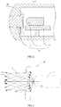
FIG. 2 is a sectional view of a structure in an A-A position inFIG. 1 ; -
FIG. 3 is a schematic diagram of an optical path in an infrared light transmit apparatus according to an implementation of this application; -
FIG. 4 is a schematic structural diagram of a light cover in an infrared light transmit apparatus according to an implementation of this application; -
FIG. 5 is a sectional view of a structure in a B-B position inFIG. 4 ; and -
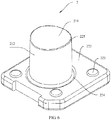
FIG. 6 is a schematic three-dimensional diagram of a light cover in an infrared light transmit apparatus according to an implementation of this application. - The following clearly and completely describes the technical solutions in the implementations of this application with reference to the accompanying drawings in the implementations of this application. Apparently, the described implementations are merely some but not all of the implementations of this application. All other implementations obtained by a person of ordinary skill in the art based on the implementations of this application without creative efforts shall fall within the protection scope of this application.
- Referring to
FIG. 1 to FIG. 6 , an implementation of this application provides an infraredlight transmit apparatus 10, including aninfrared light transmitter 1 and alight cover 2. - Specifically, the
light cover 2 includes afixing post 21 and apositioning station 22. - The
fixing post 21 includes a light-in surface (not shown in the figure) and a light-outsurface 211 that are disposed opposite to each other and includes aside surface 212 connecting the light-in surface and the light-outsurface 211. The light-in surface is connected to the positioning station 22 (in this case, the light-outsurface 211 is away from the positioning station 22). Theside surface 212 fits ahousing 20 of amobile terminal 100, so that thelight cover 2 is fastened to thehousing 20. - A
light concentration surface 221 is formed on a side that is of thepositioning station 22 and that is away from thefixing post 21, thelight concentration surface 221 includes a concave curved surface, and thelight concentration surface 221 faces towards theinfrared light transmitter 1 to receive infrared light transmitted by theinfrared light transmitter 1. - In this implementation, because the
light concentration surface 221 is formed on thelight cover 2, and thelight concentration surface 221 includes the concave curved surface and has a light concentration function, the infrared light transmitted by theinfrared light transmitter 1 can pass through thelight concentration surface 221 to enter thelight cover 2 and can be transmitted from the light-out surface 211 (an optical path shown inFIG. 3 ). In other words, the infrared light can be smoothly transmitted from thehousing 20. Therefore, an energy loss of an infrared light signal in a transmission process is very low, and a remote control capability of the infrared light transmitapparatus 10 is strong. - It should be understood that the "concave curved surface" indicates that a middle part of the curved surface is curved into the
positioning station 22 relative to an edge of the curved surface. In an optional implementation, thelight concentration surface 221 includes only the curved surface, and therefore the curved surface is a surface denoted by 221. - Further, referring to
FIG. 3 andFIG. 5 , in a preferred implementation, the fixingpost 21 is cylindrical and has a firstcentral axis 33, thelight concentration surface 221 is centrally symmetric and has a secondcentral axis 31, and the firstcentral axis 33, the secondcentral axis 31, and asymmetric axis 32 of the infraredlight transmitter 1 in a light-out direction are collinear. In this way, thelight concentration surface 221 has a better light concentration effect, and the circular fixingpost 21 can better transmit an infrared light signal, to reduce an energy loss of the infrared light signal during transmission in thelight cover 2. - It can be understood that in another implementation, when the
symmetric axis 32 is eccentrically disposed relative to thelight concentration surface 221, thelight concentration surface 221 is no longer centrally symmetric, and a wave on thelight concentration surface 221 extends from an eccentric point (not shown in the figure) on thelight concentration surface 221 to an edge of thelight concentration surface 221, and the eccentric point faces towards thesymmetric axis 32, so that thelight concentration surface 221 also has a better light concentration effect. - Further, referring to
FIG. 1 to FIG. 6 , a shape of the light-out surface 211 is designed to fit a surface shape of thehousing 20, for example, a smooth arc-shaped surface, so that a light-out angle of the light-out surface 211 is relatively large. - Further, referring to
FIG. 1 to FIG. 3 andFIG. 5 , in a preferred implementation, an area of thelight concentration surface 221 is a first area, a cross-sectional area that is of the fixingpost 21 and that is in a direction perpendicular to the firstcentral axis 33 is a second area, and the first area is greater than the second area. In this case, due to the light concentration function of thelight concentration surface 221, light in a larger angle can be concentrated into light in a smaller angle, the infrared light transmitted by the infraredlight transmitter 1 can be smoothly transmitted from thelight concentration surface 221 with a larger area to the fixingpost 21 with a smaller cross-sectional area, and an energy loss is low. In addition, because thelight concentration surface 221 has a larger area, thelight cover 2 can receive more infrared light to ensure the remote control capability of the infrared light transmitapparatus 10. Further, because the fixingpost 21 has a smaller cross-sectional area, a volume of thelight cover 2 is reduced, and a volume of thehousing 20 is reduced. This meets a design requirement for miniaturizing themobile terminal 100. - It should be noted that the area of the
light concentration surface 221 indicates an area of a region encircled by edges of thelight concentration surface 221. - Further, referring to
FIG. 3 andFIG. 5 , in a preferred implementation, the curved surface of thelight concentration surface 221 is wavy. Specifically, thelight concentration surface 221 includes a plurality ofpeaks 2213 with different curvatures and a plurality ofvalleys 2214 with different curvatures, and the plurality ofpeaks 2213 and the plurality ofvalleys 2214 are connected alternately and smoothly, to form the wavy curved surface. When thelight concentration surface 221 is centrally symmetric, a wave extends from a center (to be specific, an intersecting point between the secondcentral axis 31 and the light concentration surface 221) of thelight concentration surface 221 to an edge of thelight concentration surface 221. In this implementation, thelight concentration surface 221 is designed to enable light entering thelight concentration surface 221 to be transmitted to the fixingpost 21, and be transmitted from the light-out surface 211 of the fixingpost 21, thereby reducing an energy loss of an infrared light signal and ensuring a strong remote control capability of the infrared light transmitapparatus 10. - Further, in a preferred implementation, the
light cover 2 is made of acrylic (also referred to as PMMA or plexiglass, sourced from acrylic (acrylic plastics) in English, and referred to polymethyl methacrylate in chemistry) material, and is configured to transmit invisible infrared light. Thelight cover 2 uses an all-in-one injection molding technology, and therefore is reliable in structure, easy to manufacture, and low-cost. - It should be understood that when the infrared
light transmitter 1 is another invisible-light transmitter, thelight cover 2 in this implementation may also be configured to transmit other invisible light. - Further, referring to
FIG. 1 to FIG. 6 , in a preferred implementation, apositioning surface 222 is formed on a side that is of thepositioning station 22 and that is close to the fixingpost 21, and thepositioning surface 222 is disposed to encircle the fixingpost 21 to press against thehousing 20. Thepositioning surface 222 may be configured to help thelight cover 2 implement positioning. - Further, referring to
FIG. 1 to FIG. 6 , in a preferred implementation, a plurality ofcushions 223 are disposed on thepositioning surface 222, and the plurality ofcushions 223 are evenly distributed around the fixingpost 21. The plurality ofcushions 223 pressing against thehousing 20 may be configured to help thelight cover 2 implement positioning. In addition, with a cushioning function, the plurality ofcushions 223 can protect thelight cover 2 from damage when themobile terminal 100 shakes violently. - Further, referring to
FIG. 2 andFIG. 6 , in a preferred implementation, agroove 224 is formed in a junction between thepositioning surface 222 and theside surface 212. In other words, an undercut design is provided in the junction between thepositioning surface 222 and theside surface 212, so that thelight cover 2 can be better mounted to thehousing 20. - Further, referring to
FIG. 2, FIG. 3 , andFIG. 6 , in a preferred implementation, adraft angle 225 is formed between the light-out surface 211 and theside surface 212, to increase an area of the light-out surface 211, reduce an energy loss of an infrared light signal, and improve a remote control capability of the infrared light transmitapparatus 10. - Further, referring to
FIG. 1 to FIG. 3 , in a preferred implementation, the infrared light transmitapparatus 10 further includes a printedcircuit board 4, the printedcircuit board 4 is disposed with a drive circuit, and the drive circuit is electrically connected to the infraredlight transmitter 1 to supply power to the infraredlight transmitter 1. - Referring to
FIG. 1 to FIG. 6 , an implementation of this application further provides amobile terminal 100, including the infrared light transmitapparatus 10 and thehousing 20 in any one of the foregoing implementations. Themobile terminal 100 has a strong remote control capability. - The
mobile terminal 100 includes but is not limited to a mobile phone, a notebook computer, a tablet computer, a POS machine, a vehicle-mounted computer, a camera, and the like. - The implementations of this application are described in detail above. The principle and implementation of this application are described herein by using specific examples. The description about the implementations is merely provided to help understand the method and core ideas of this application. In addition, a person of ordinary skill in the art can make modifications to this application in terms of the specific implementations and application scopes according to the ideas of this application. Therefore, the content of this specification shall not be construed as a limitation to this application.
Claims (9)
- An infrared light transmit apparatus (10), comprising an infrared light transmitter (1) and a light cover (2), wherein the light cover (2) comprises a fixing post (21) and a positioning station (22) that are connected to each other;
the fixing post (21) comprises a light-in surface and a light-out surface (211) that are disposed opposite to each other and comprises a side surface (212) connecting the light-in surface and the light-out surface (211), the light-in surface is connected to the positioning station (22), and the side surface (212) is configured to fit a housing (20) of a mobile terminal (100); and
a light concentration surface (221) is formed on a side that is of the positioning station (22) and that is away from the fixing post (21), the light concentration surface (221) comprises a wavy concave curved surface, and the light concentration surface (221) faces towards the infrared light transmitter (1) to receive infrared light transmitted by the infrared light transmitter (1),
wherein the light concentration surface (221) comprises a plurality of peaks (2213) with different curvatures and a plurality of valleys (2214) with different curvatures, and the plurality of peaks (2213) and the plurality of valleys (2214) are connected alternately and smoothly, to form the wavy concave curved surface. - The infrared light transmit apparatus (10) according to claim 1, wherein the fixing post (21) is cylindrical and has a first central axis (33), the light concentration surface (221) is centrally symmetric and has a second central axis (31), and the first central axis (33), the second central axis (31), and a symmetric axis (32) of the infrared light transmitter (1) in a light-out direction are collinear.
- The infrared light transmit apparatus (10) according to claim 2, wherein an area of the light concentration surface (221) is a first area, a cross-sectional area that is of the fixing post (21) and that is in a direction perpendicular to the first central axis (33) is a second area, and the first area is greater than the second area.
- The infrared light transmit apparatus (10) according to any one of claims 1 to 3, wherein the light cover (2) is made of acrylic material.
- The infrared light transmit apparatus (10) according to any one of claims 1 to 3, wherein a positioning surface is formed on a side that is of the positioning station (22) and that is close to the fixing post (21), and the positioning surface is disposed to encircle the fixing post (21) to press against the housing (20).
- The infrared light transmit apparatus (10) according to claim 5, wherein a plurality of cushions (223) are disposed on the positioning surface, and the plurality of cushions (223) are evenly distributed around the fixing post (21).
- The infrared light transmit apparatus (10) according to claim 5, wherein a groove (224) is formed in a junction between the positioning surface and the side surface (212).
- The infrared light transmit apparatus (10) according to any one of claims 1 to 7, wherein the infrared light transmit apparatus (10) further comprises a drive circuit, and the drive circuit is electrically connected to the infrared light transmitter (1) to supply power to the infrared light transmitter (1).
- A mobile terminal, comprising the infrared light transmit apparatus (10) according to any one of claims 1 to 8.
Applications Claiming Priority (1)
| Application Number | Priority Date | Filing Date | Title |
|---|---|---|---|
| PCT/CN2016/086888 WO2017219316A1 (en) | 2016-06-23 | 2016-06-23 | Infrared light-emitting device, and mobile terminal |
Publications (3)
| Publication Number | Publication Date |
|---|---|
| EP3467798A1 EP3467798A1 (en) | 2019-04-10 |
| EP3467798A4 EP3467798A4 (en) | 2019-05-29 |
| EP3467798B1 true EP3467798B1 (en) | 2020-10-21 |
Family
ID=60783139
Family Applications (1)
| Application Number | Title | Priority Date | Filing Date |
|---|---|---|---|
| EP16905858.3A Active EP3467798B1 (en) | 2016-06-23 | 2016-06-23 | Infrared light-emitting device, and mobile terminal |
Country Status (4)
| Country | Link |
|---|---|
| US (1) | US11462098B2 (en) |
| EP (1) | EP3467798B1 (en) |
| CN (1) | CN108496210B (en) |
| WO (1) | WO2017219316A1 (en) |
Families Citing this family (3)
| Publication number | Priority date | Publication date | Assignee | Title |
|---|---|---|---|---|
| KR102346598B1 (en) * | 2020-10-20 | 2022-01-03 | 부전전자 주식회사 | IR Window Package in headset |
| CN113421416B (en) | 2021-06-17 | 2023-04-07 | 维沃移动通信有限公司 | Electronic device |
| CN114399898B (en) * | 2022-01-12 | 2023-03-17 | 维沃移动通信有限公司 | Electronic device |
Family Cites Families (16)
| Publication number | Priority date | Publication date | Assignee | Title |
|---|---|---|---|---|
| JPH11211202A (en) * | 1998-01-22 | 1999-08-06 | Matsushita Electric Ind Co Ltd | Remote control light emitting device |
| CN2831294Y (en) * | 2005-09-21 | 2006-10-25 | 深圳Tcl新技术有限公司 | Light conductive pole of increasing angle remote controlled sensitivity and remote controlled angle |
| CA2545124A1 (en) * | 2006-04-28 | 2007-10-28 | Nien Made Enterprise Co., Ltd. | Remote control with narrowed acting angle |
| CN201129669Y (en) * | 2007-12-25 | 2008-10-08 | 青岛海信电器股份有限公司 | Light guide pole, remote control panel and component thereof |
| CN202178725U (en) * | 2011-07-29 | 2012-03-28 | 河南思可达光伏材料股份有限公司 | Condensing ultra-white pattern glass used for solar photovoltaic cell |
| CN102375238B (en) | 2011-11-08 | 2014-05-07 | 中国科学院上海光学精密机械研究所 | Micro cylindrical mirror array for generating uniform illumination and designing method thereof |
| CN102590925B (en) * | 2012-02-21 | 2014-07-09 | 华为终端有限公司 | Light guiding component and electronic equipment with same |
| JP5866431B2 (en) * | 2012-03-13 | 2016-02-17 | シャープ株式会社 | Light emitting device and backlight device |
| CN202931491U (en) * | 2012-11-02 | 2013-05-08 | 康佳集团股份有限公司 | Infrared signal 3D transmitting device and 3D television thereof |
| CN203810278U (en) * | 2014-03-31 | 2014-09-03 | 中山市恒辰光电科技有限公司 | Novel LED (Light Emitting Diode) optical lens |
| CN104676426A (en) * | 2015-03-11 | 2015-06-03 | 苏州昆仑工业设计有限公司 | LED (Light-Emitting Diode) colorful color-changeable flower-shaped lamp |
| CN204650741U (en) | 2015-04-08 | 2015-09-16 | 深圳市金立通信设备有限公司 | A kind of infrared light emission device and mobile terminal |
| CN105020654B (en) * | 2015-08-03 | 2017-03-08 | 台州市黄岩广环工贸有限公司 | There is the headlight lamp group structure of the dual light area of horizontal hot spot |
| CN205065604U (en) | 2015-09-22 | 2016-03-02 | 天津市金汇兴自行车有限公司 | Communications facilities flash light lamp shade |
| CN205139410U (en) | 2015-10-29 | 2016-04-06 | 东莞酷派软件技术有限公司 | Astigmatism piece and mobile terminal |
| CN105572834A (en) * | 2016-01-27 | 2016-05-11 | 珠海格力电器股份有限公司 | Lens and remote control device |
-
2016
- 2016-06-23 CN CN201680079780.0A patent/CN108496210B/en active Active
- 2016-06-23 US US16/312,609 patent/US11462098B2/en active Active
- 2016-06-23 EP EP16905858.3A patent/EP3467798B1/en active Active
- 2016-06-23 WO PCT/CN2016/086888 patent/WO2017219316A1/en not_active Ceased
Non-Patent Citations (1)
| Title |
|---|
| None * |
Also Published As
| Publication number | Publication date |
|---|---|
| US20190333368A1 (en) | 2019-10-31 |
| US11462098B2 (en) | 2022-10-04 |
| CN108496210A (en) | 2018-09-04 |
| EP3467798A1 (en) | 2019-04-10 |
| WO2017219316A1 (en) | 2017-12-28 |
| CN108496210B (en) | 2020-04-28 |
| EP3467798A4 (en) | 2019-05-29 |
Similar Documents
| Publication | Publication Date | Title |
|---|---|---|
| US10516814B2 (en) | Camera assembly and electronic device | |
| US10951824B2 (en) | Electronic apparatus and mobile terminal | |
| EP3557369B1 (en) | Terminal | |
| US10890940B2 (en) | Display screen, terminal display screen assembly, and mobile terminal | |
| US8190021B2 (en) | Smart phone with lens | |
| EP2755367B1 (en) | Frame structure for preventing deformation, and electronic device including the same | |
| KR101472675B1 (en) | Dual camera module | |
| US11057507B2 (en) | Electronic assembly and electronic device | |
| EP4329276B1 (en) | Electronic device | |
| US11462098B2 (en) | Infrared light transmit apparatus and mobile terminal | |
| CN107547997A (en) | Circuit board assembly and electronic equipment | |
| US20240188238A1 (en) | Slidable housing including drive motor and electronic device including the same | |
| CN112335121B (en) | Antenna clip and electronic device comprising same | |
| CN116569542B (en) | An electronic device | |
| US12506824B2 (en) | Electronic device with camera assembly | |
| WO2023103450A1 (en) | Electronic assembly and electronic apparatus | |
| CN111385444A (en) | Camera module and display module and terminal device at camera module | |
| US11405537B2 (en) | Camera assembly and electronic device having the same | |
| CN207867192U (en) | Camera lens module | |
| KR20140116707A (en) | Connector of electronic device and electronic device using the same | |
| US11156747B2 (en) | Glass lens and lens module using the same | |
| CN219302736U (en) | Optical sensor module and electronic device | |
| CN206178321U (en) | Camera assembly and mobile terminal | |
| US20130106344A1 (en) | Connector interface for a charger device | |
| JP2020150468A (en) | Mobile terminal |
Legal Events
| Date | Code | Title | Description |
|---|---|---|---|
| STAA | Information on the status of an ep patent application or granted ep patent |
Free format text: STATUS: THE INTERNATIONAL PUBLICATION HAS BEEN MADE |
|
| PUAI | Public reference made under article 153(3) epc to a published international application that has entered the european phase |
Free format text: ORIGINAL CODE: 0009012 |
|
| STAA | Information on the status of an ep patent application or granted ep patent |
Free format text: STATUS: REQUEST FOR EXAMINATION WAS MADE |
|
| 17P | Request for examination filed |
Effective date: 20190104 |
|
| AK | Designated contracting states |
Kind code of ref document: A1 Designated state(s): AL AT BE BG CH CY CZ DE DK EE ES FI FR GB GR HR HU IE IS IT LI LT LU LV MC MK MT NL NO PL PT RO RS SE SI SK SM TR |
|
| AX | Request for extension of the european patent |
Extension state: BA ME |
|
| A4 | Supplementary search report drawn up and despatched |
Effective date: 20190429 |
|
| RIC1 | Information provided on ipc code assigned before grant |
Ipc: G02B 6/00 20060101ALI20190423BHEP Ipc: G08C 23/04 20060101AFI20190423BHEP |
|
| DAV | Request for validation of the european patent (deleted) | ||
| DAX | Request for extension of the european patent (deleted) | ||
| GRAP | Despatch of communication of intention to grant a patent |
Free format text: ORIGINAL CODE: EPIDOSNIGR1 |
|
| STAA | Information on the status of an ep patent application or granted ep patent |
Free format text: STATUS: GRANT OF PATENT IS INTENDED |
|
| INTG | Intention to grant announced |
Effective date: 20200506 |
|
| GRAS | Grant fee paid |
Free format text: ORIGINAL CODE: EPIDOSNIGR3 |
|
| GRAA | (expected) grant |
Free format text: ORIGINAL CODE: 0009210 |
|
| STAA | Information on the status of an ep patent application or granted ep patent |
Free format text: STATUS: THE PATENT HAS BEEN GRANTED |
|
| AK | Designated contracting states |
Kind code of ref document: B1 Designated state(s): AL AT BE BG CH CY CZ DE DK EE ES FI FR GB GR HR HU IE IS IT LI LT LU LV MC MK MT NL NO PL PT RO RS SE SI SK SM TR |
|
| REG | Reference to a national code |
Ref country code: GB Ref legal event code: FG4D |
|
| REG | Reference to a national code |
Ref country code: CH Ref legal event code: EP |
|
| REG | Reference to a national code |
Ref country code: IE Ref legal event code: FG4D |
|
| REG | Reference to a national code |
Ref country code: AT Ref legal event code: REF Ref document number: 1326637 Country of ref document: AT Kind code of ref document: T Effective date: 20201115 |
|
| REG | Reference to a national code |
Ref country code: DE Ref legal event code: R096 Ref document number: 602016046521 Country of ref document: DE |
|
| REG | Reference to a national code |
Ref country code: AT Ref legal event code: MK05 Ref document number: 1326637 Country of ref document: AT Kind code of ref document: T Effective date: 20201021 |
|
| REG | Reference to a national code |
Ref country code: NL Ref legal event code: MP Effective date: 20201021 |
|
| PG25 | Lapsed in a contracting state [announced via postgrant information from national office to epo] |
Ref country code: GR Free format text: LAPSE BECAUSE OF FAILURE TO SUBMIT A TRANSLATION OF THE DESCRIPTION OR TO PAY THE FEE WITHIN THE PRESCRIBED TIME-LIMIT Effective date: 20210122 Ref country code: FI Free format text: LAPSE BECAUSE OF FAILURE TO SUBMIT A TRANSLATION OF THE DESCRIPTION OR TO PAY THE FEE WITHIN THE PRESCRIBED TIME-LIMIT Effective date: 20201021 Ref country code: RS Free format text: LAPSE BECAUSE OF FAILURE TO SUBMIT A TRANSLATION OF THE DESCRIPTION OR TO PAY THE FEE WITHIN THE PRESCRIBED TIME-LIMIT Effective date: 20201021 Ref country code: PT Free format text: LAPSE BECAUSE OF FAILURE TO SUBMIT A TRANSLATION OF THE DESCRIPTION OR TO PAY THE FEE WITHIN THE PRESCRIBED TIME-LIMIT Effective date: 20210222 Ref country code: NO Free format text: LAPSE BECAUSE OF FAILURE TO SUBMIT A TRANSLATION OF THE DESCRIPTION OR TO PAY THE FEE WITHIN THE PRESCRIBED TIME-LIMIT Effective date: 20210121 |
|
| REG | Reference to a national code |
Ref country code: LT Ref legal event code: MG4D |
|
| PG25 | Lapsed in a contracting state [announced via postgrant information from national office to epo] |
Ref country code: SE Free format text: LAPSE BECAUSE OF FAILURE TO SUBMIT A TRANSLATION OF THE DESCRIPTION OR TO PAY THE FEE WITHIN THE PRESCRIBED TIME-LIMIT Effective date: 20201021 Ref country code: BG Free format text: LAPSE BECAUSE OF FAILURE TO SUBMIT A TRANSLATION OF THE DESCRIPTION OR TO PAY THE FEE WITHIN THE PRESCRIBED TIME-LIMIT Effective date: 20210121 Ref country code: LV Free format text: LAPSE BECAUSE OF FAILURE TO SUBMIT A TRANSLATION OF THE DESCRIPTION OR TO PAY THE FEE WITHIN THE PRESCRIBED TIME-LIMIT Effective date: 20201021 Ref country code: PL Free format text: LAPSE BECAUSE OF FAILURE TO SUBMIT A TRANSLATION OF THE DESCRIPTION OR TO PAY THE FEE WITHIN THE PRESCRIBED TIME-LIMIT Effective date: 20201021 Ref country code: IS Free format text: LAPSE BECAUSE OF FAILURE TO SUBMIT A TRANSLATION OF THE DESCRIPTION OR TO PAY THE FEE WITHIN THE PRESCRIBED TIME-LIMIT Effective date: 20210221 Ref country code: AT Free format text: LAPSE BECAUSE OF FAILURE TO SUBMIT A TRANSLATION OF THE DESCRIPTION OR TO PAY THE FEE WITHIN THE PRESCRIBED TIME-LIMIT Effective date: 20201021 Ref country code: ES Free format text: LAPSE BECAUSE OF FAILURE TO SUBMIT A TRANSLATION OF THE DESCRIPTION OR TO PAY THE FEE WITHIN THE PRESCRIBED TIME-LIMIT Effective date: 20201021 |
|
| REG | Reference to a national code |
Ref country code: DE Ref legal event code: R081 Ref document number: 602016046521 Country of ref document: DE Owner name: HONOR DEVICE CO., LTD., SHENZHEN, CN Free format text: FORMER OWNER: HUAWEI TECHNOLOGIES CO., LTD., SHENZHEN, GUANGDONG, CN |
|
| PG25 | Lapsed in a contracting state [announced via postgrant information from national office to epo] |
Ref country code: NL Free format text: LAPSE BECAUSE OF FAILURE TO SUBMIT A TRANSLATION OF THE DESCRIPTION OR TO PAY THE FEE WITHIN THE PRESCRIBED TIME-LIMIT Effective date: 20201021 Ref country code: HR Free format text: LAPSE BECAUSE OF FAILURE TO SUBMIT A TRANSLATION OF THE DESCRIPTION OR TO PAY THE FEE WITHIN THE PRESCRIBED TIME-LIMIT Effective date: 20201021 |
|
| REG | Reference to a national code |
Ref country code: DE Ref legal event code: R097 Ref document number: 602016046521 Country of ref document: DE |
|
| PG25 | Lapsed in a contracting state [announced via postgrant information from national office to epo] |
Ref country code: SM Free format text: LAPSE BECAUSE OF FAILURE TO SUBMIT A TRANSLATION OF THE DESCRIPTION OR TO PAY THE FEE WITHIN THE PRESCRIBED TIME-LIMIT Effective date: 20201021 Ref country code: LT Free format text: LAPSE BECAUSE OF FAILURE TO SUBMIT A TRANSLATION OF THE DESCRIPTION OR TO PAY THE FEE WITHIN THE PRESCRIBED TIME-LIMIT Effective date: 20201021 Ref country code: EE Free format text: LAPSE BECAUSE OF FAILURE TO SUBMIT A TRANSLATION OF THE DESCRIPTION OR TO PAY THE FEE WITHIN THE PRESCRIBED TIME-LIMIT Effective date: 20201021 Ref country code: CZ Free format text: LAPSE BECAUSE OF FAILURE TO SUBMIT A TRANSLATION OF THE DESCRIPTION OR TO PAY THE FEE WITHIN THE PRESCRIBED TIME-LIMIT Effective date: 20201021 Ref country code: SK Free format text: LAPSE BECAUSE OF FAILURE TO SUBMIT A TRANSLATION OF THE DESCRIPTION OR TO PAY THE FEE WITHIN THE PRESCRIBED TIME-LIMIT Effective date: 20201021 Ref country code: RO Free format text: LAPSE BECAUSE OF FAILURE TO SUBMIT A TRANSLATION OF THE DESCRIPTION OR TO PAY THE FEE WITHIN THE PRESCRIBED TIME-LIMIT Effective date: 20201021 |
|
| PLBE | No opposition filed within time limit |
Free format text: ORIGINAL CODE: 0009261 |
|
| STAA | Information on the status of an ep patent application or granted ep patent |
Free format text: STATUS: NO OPPOSITION FILED WITHIN TIME LIMIT |
|
| PG25 | Lapsed in a contracting state [announced via postgrant information from national office to epo] |
Ref country code: DK Free format text: LAPSE BECAUSE OF FAILURE TO SUBMIT A TRANSLATION OF THE DESCRIPTION OR TO PAY THE FEE WITHIN THE PRESCRIBED TIME-LIMIT Effective date: 20201021 |
|
| REG | Reference to a national code |
Ref country code: GB Ref legal event code: 732E Free format text: REGISTERED BETWEEN 20210812 AND 20210818 |
|
| 26N | No opposition filed |
Effective date: 20210722 |
|
| PG25 | Lapsed in a contracting state [announced via postgrant information from national office to epo] |
Ref country code: AL Free format text: LAPSE BECAUSE OF FAILURE TO SUBMIT A TRANSLATION OF THE DESCRIPTION OR TO PAY THE FEE WITHIN THE PRESCRIBED TIME-LIMIT Effective date: 20201021 Ref country code: IT Free format text: LAPSE BECAUSE OF FAILURE TO SUBMIT A TRANSLATION OF THE DESCRIPTION OR TO PAY THE FEE WITHIN THE PRESCRIBED TIME-LIMIT Effective date: 20201021 |
|
| PG25 | Lapsed in a contracting state [announced via postgrant information from national office to epo] |
Ref country code: SI Free format text: LAPSE BECAUSE OF FAILURE TO SUBMIT A TRANSLATION OF THE DESCRIPTION OR TO PAY THE FEE WITHIN THE PRESCRIBED TIME-LIMIT Effective date: 20201021 |
|
| PG25 | Lapsed in a contracting state [announced via postgrant information from national office to epo] |
Ref country code: MC Free format text: LAPSE BECAUSE OF FAILURE TO SUBMIT A TRANSLATION OF THE DESCRIPTION OR TO PAY THE FEE WITHIN THE PRESCRIBED TIME-LIMIT Effective date: 20201021 |
|
| REG | Reference to a national code |
Ref country code: CH Ref legal event code: PL |
|
| REG | Reference to a national code |
Ref country code: BE Ref legal event code: MM Effective date: 20210630 |
|
| PG25 | Lapsed in a contracting state [announced via postgrant information from national office to epo] |
Ref country code: LU Free format text: LAPSE BECAUSE OF NON-PAYMENT OF DUE FEES Effective date: 20210623 |
|
| PG25 | Lapsed in a contracting state [announced via postgrant information from national office to epo] |
Ref country code: LI Free format text: LAPSE BECAUSE OF NON-PAYMENT OF DUE FEES Effective date: 20210630 Ref country code: IE Free format text: LAPSE BECAUSE OF NON-PAYMENT OF DUE FEES Effective date: 20210623 Ref country code: CH Free format text: LAPSE BECAUSE OF NON-PAYMENT OF DUE FEES Effective date: 20210630 |
|
| PG25 | Lapsed in a contracting state [announced via postgrant information from national office to epo] |
Ref country code: IS Free format text: LAPSE BECAUSE OF FAILURE TO SUBMIT A TRANSLATION OF THE DESCRIPTION OR TO PAY THE FEE WITHIN THE PRESCRIBED TIME-LIMIT Effective date: 20210221 |
|
| PG25 | Lapsed in a contracting state [announced via postgrant information from national office to epo] |
Ref country code: BE Free format text: LAPSE BECAUSE OF NON-PAYMENT OF DUE FEES Effective date: 20210630 |
|
| PG25 | Lapsed in a contracting state [announced via postgrant information from national office to epo] |
Ref country code: CY Free format text: LAPSE BECAUSE OF FAILURE TO SUBMIT A TRANSLATION OF THE DESCRIPTION OR TO PAY THE FEE WITHIN THE PRESCRIBED TIME-LIMIT Effective date: 20201021 |
|
| PG25 | Lapsed in a contracting state [announced via postgrant information from national office to epo] |
Ref country code: HU Free format text: LAPSE BECAUSE OF FAILURE TO SUBMIT A TRANSLATION OF THE DESCRIPTION OR TO PAY THE FEE WITHIN THE PRESCRIBED TIME-LIMIT; INVALID AB INITIO Effective date: 20160623 |
|
| PG25 | Lapsed in a contracting state [announced via postgrant information from national office to epo] |
Ref country code: MK Free format text: LAPSE BECAUSE OF FAILURE TO SUBMIT A TRANSLATION OF THE DESCRIPTION OR TO PAY THE FEE WITHIN THE PRESCRIBED TIME-LIMIT Effective date: 20201021 |
|
| PG25 | Lapsed in a contracting state [announced via postgrant information from national office to epo] |
Ref country code: TR Free format text: LAPSE BECAUSE OF FAILURE TO SUBMIT A TRANSLATION OF THE DESCRIPTION OR TO PAY THE FEE WITHIN THE PRESCRIBED TIME-LIMIT Effective date: 20201021 |
|
| PG25 | Lapsed in a contracting state [announced via postgrant information from national office to epo] |
Ref country code: MT Free format text: LAPSE BECAUSE OF FAILURE TO SUBMIT A TRANSLATION OF THE DESCRIPTION OR TO PAY THE FEE WITHIN THE PRESCRIBED TIME-LIMIT Effective date: 20201021 |
|
| PGFP | Annual fee paid to national office [announced via postgrant information from national office to epo] |
Ref country code: GB Payment date: 20260508 Year of fee payment: 11 |
|
| PGFP | Annual fee paid to national office [announced via postgrant information from national office to epo] |
Ref country code: DE Payment date: 20260506 Year of fee payment: 11 |
|
| PGFP | Annual fee paid to national office [announced via postgrant information from national office to epo] |
Ref country code: FR Payment date: 20260511 Year of fee payment: 11 |