EP3467794A1 - Paper sheet information collection device and paper sheet information collection method - Google Patents
Paper sheet information collection device and paper sheet information collection method Download PDFInfo
- Publication number
- EP3467794A1 EP3467794A1 EP16903096.2A EP16903096A EP3467794A1 EP 3467794 A1 EP3467794 A1 EP 3467794A1 EP 16903096 A EP16903096 A EP 16903096A EP 3467794 A1 EP3467794 A1 EP 3467794A1
- Authority
- EP
- European Patent Office
- Prior art keywords
- collection
- sheet
- data
- thresholds
- data collection
- Prior art date
- Legal status (The legal status is an assumption and is not a legal conclusion. Google has not performed a legal analysis and makes no representation as to the accuracy of the status listed.)
- Granted
Links
Images




Classifications
-
- G—PHYSICS
- G07—CHECKING-DEVICES
- G07D—HANDLING OF COINS OR VALUABLE PAPERS, e.g. TESTING, SORTING BY DENOMINATIONS, COUNTING, DISPENSING, CHANGING OR DEPOSITING
- G07D7/00—Testing specially adapted to determine the identity or genuineness of valuable papers or for segregating those which are unacceptable, e.g. banknotes that are alien to a currency
- G07D7/181—Testing mechanical properties or condition, e.g. wear or tear
- G07D7/185—Detecting holes or pores
-
- G—PHYSICS
- G07—CHECKING-DEVICES
- G07D—HANDLING OF COINS OR VALUABLE PAPERS, e.g. TESTING, SORTING BY DENOMINATIONS, COUNTING, DISPENSING, CHANGING OR DEPOSITING
- G07D7/00—Testing specially adapted to determine the identity or genuineness of valuable papers or for segregating those which are unacceptable, e.g. banknotes that are alien to a currency
-
- G—PHYSICS
- G07—CHECKING-DEVICES
- G07D—HANDLING OF COINS OR VALUABLE PAPERS, e.g. TESTING, SORTING BY DENOMINATIONS, COUNTING, DISPENSING, CHANGING OR DEPOSITING
- G07D11/00—Devices accepting coins; Devices accepting, dispensing, sorting or counting valuable papers
- G07D11/20—Controlling or monitoring the operation of devices; Data handling
- G07D11/22—Means for sensing or detection
- G07D11/235—Means for sensing or detection for monitoring or indicating operating conditions; for detecting malfunctions
Definitions
- the present invention relates to sheet information collection devices and sheet information collection methods. More specifically, the present invention relates to a sheet information collection device suitable as a sheet recognition device configured to acquire information, including images, positions, and sizes, of sheets such as banknotes, gift vouchers, cheques, and card-like media; and a sheet information collection method.
- Sheets such as banknotes (printed money), gift vouchers, and cheques have a variety of security characteristics for anti-counterfeiting.
- paper made of vegetable fibers is usually used for sheets
- paper made of synthetic fibers or a polymer sheet made of synthetic resin may be used in order to improve the properties such as durability, water resistance, and security.
- Banknotes made of polymer sheets are called polymer banknotes. Polymer banknotes having a clear window (transparent window) are difficult to counterfeit.
- an optical sensor such as an optical line sensor is usually used.
- a clear window is a transparent portion transmitting light emitted from the optical sensor.
- a sheet having a transparent portion may therefore need to undergo different processes from a common sheet having no transparent portion.
- Patent Literature 1 discloses a sheet handling machine as a technique to prevent false detection of abnormal transport due to an island-shaped window formed in a banknote.
- the sheet handling machine stops operation of identifying the passage of the rear edge portion at a position corresponding to one transport path sensor during a preset period from a time point when the absence of a banknote is detected if the absence of the banknote is detected after judgement of passage of the banknote at the position corresponding to the one transport path sensor among a plurality of transport path sensors disposed along a transport path.
- Patent Literature 1 WO 2009/075015
- the size and/or position of a clear window of a sheet may be out of the scope of the specification of a conventional sheet handling machine.
- the sheet handling machine in such a case may falsely determine the clear window as the rear edge (the endmost edge) of the sheet, stop collection of transmissive light data from an optical sensor such as an optical line sensor, and falsely detect the portion of the sheet coming after the clear window as another sheet. For example, if a sheet has a wide, belt-shaped clear window from one edge to the other edge in its short edge direction, the technique disclosed in Patent Literature 1 can cause false detection.
- the machine can be configured not to stop collection of transmissive light data as long as the width of the region in the transport direction is not greater than a predetermined threshold. Still, the machine would falsely determine the clear window as the rear edge of a sheet if the clear window extends beyond the threshold, stopping collection of transmissive light data.
- the threshold can simply be increased, but then the following disadvantages arise.
- an object of the present invention is to provide a sheet information collection device which can reduce extra data to be collected after the detection of the rear edge of a sheet and reduce false detection of the rear edge of a sheet having a transparent portion; and a sheet information collection method.
- a first aspect of the present invention is a sheet information collection device for collecting information of a sheet comprising a transparent portion, the device comprising: a transporter configured to transport the sheet; an optical sensor configured to scan the transported sheet in a transport direction and output transmissive light data acquired at a plurality of collection points set in the transport direction; a data collector configured to collect the transmissive light data from the optical sensor; a determiner configured to determine transmission or blocking of light at each collection point based on the transmissive light data; a recorder configured to store thresholds for data collection stop determination set for the collection points; and a data collection stopper configured to stop collection of the transmissive light data by the data collector when the determiner determines that light is transmitted at successive collection points in the transport direction and the number of the successive collection points is equal to or greater than one of the thresholds for data collection stop determination corresponding to the successive collection points, wherein among the thresholds for data collection stop determination, a threshold for data collection stop determination corresponding to a rearmost edge region of the sheet is smaller than the thresholds for
- the optical sensor comprises an optical line sensor in which a plurality of pixels are disposed in a line in a width direction perpendicular to the transport direction.
- the recorder further stores a threshold for medium presence or absence determination, and the determiner determines transmission or blocking of light for transmissive light data successively acquired from the line of pixels based on the transmissive light data from the line of the pixels and the threshold for medium presence or absence determination.
- the transparent portion extends from one edge to the other edge in the width direction.
- the sheet information collection device is capable of collecting information of a plurality of types of sheets each including a transparent portion, and the data collection stopper switches among the thresholds for data collection stop determination based on a length in the transport direction of a sheet whose length in the transport direction is the shortest among the plurality of types of sheets.
- the data collection stopper switches among the thresholds for data collection stop determination after the transparent portion is detected.
- the sheet information collection device is capable of collecting information of a plurality of types of sheets each comprising a transparent portion, and the data collection stopper switches among the thresholds for data collection determination based on the type of the target sheet.
- the data collection stopper stops collection of the transmissive light data by the optical sensor based on a threshold for data collection stop determination corresponding to a region other than the rearmost edge region of the sheet among the plurality of thresholds for data collection stop determination.
- the data collection stopper stops collection of the transmissive light data by the optical sensor based on a threshold for data collection stop determination corresponding to a frontmost edge region of the sheet without switching among the thresholds for data collection stop determination.
- the sheet information collection device is capable of collecting information of a plurality of types of sheets each comprising a transparent portion, the recorder stores thresholds for data collection stop determination that are set for the respective types of the sheets, and the data collection stopper switches among the thresholds for data collection stop determination according to the type of the target sheet.
- a second aspect of the present invention is a sheet information collection method for collecting information of a sheet comprising a transparent portion, the method comprising: an output step of scanning the transported sheet in a transport direction and outputting transmissive light data at collection points set in the transport direction; a collection step of collecting transmissive light data from an optical sensor; a determination step of determining transmission or blocking of light at each collection point based on the transmissive light data; and a processing step of stopping collection of the transmissive light data in the data collection step based on thresholds for data collection stop determination set for the plurality of collection points, wherein the processing step comprises stopping collection of the transmissive light data in the data collection step when the determiner determines that light is transmitted at successive collection points in the transport direction and the number of the successive collection points is equal to or greater than one of the thresholds for data collection stop determination corresponding to the successive collection points, and among the thresholds for data collection stop determination, a threshold for data collection stop determination corresponding to a rearmost edge region of the sheet is smaller than the thresholds for data collection
- the sheet information collection device and the sheet information collection method according to the present invention can reduce extra data to be collected after the detection of the rear edge of a sheet and reduce false detection of the rear edge of a sheet having a transparent portion.
- the sheet information collection device and the sheet information collection method according to the present invention are described in detail below with reference to the attached drawings.
- the sheet information collection device and the sheet information collection method according to the present invention can be utilized in a variety of fields.
- the sheet information collection device and the sheet information collection method according to the present invention are described based on an example in which these device and method are applied to a sheet recognition device utilizing sheet images for recognition of the type of a sheet, authentication of the sheet, and reading of symbols such as characters printed on the sheet, and to a sheet handling machine utilizing the sheet recognition device.
- the present embodiment is an embodiment of a sheet information collection device and a sheet information collection method which collect image information as the information of a sheet.
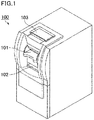
- a sheet handling machine 100 of the present embodiment is used to deposit and dispense sheets, and includes a sheet inlet 101, a sheet outlet 102, an operation/display unit 103, and a sheet recognition device (not illustrated).
- the operation/display unit 103 functions as an input device for inputting various pieces of information required to use the sheet handling machine 100, and also functions as an output device for outputting various pieces of information on the display.
- the sheet recognition device in the present embodiment is used to capture an image of a banknote, a cheque, or a gift voucher, for example, inside the sheet handling machine 100.
- the sheet recognition device in the present embodiment utilizes the image of the sheet captured by a sheet information collection device including an optical line sensor to recognize the type of the sheet (the denomination, in the case of a banknote), authenticate the sheet, determine the fitness of the sheet, or recognize the type of a document of value such as a cheque or a gift voucher.
- the sheet recognition device also utilizes the image of the sheet to read the serial number of a banknote or characters printed on a document of value, for example.
- the method and device to deposit and dispense a sheet such as a banknote, the sheet recognition and character recognition utilizing images of sheets such as banknotes, and the device executing these processes can be conventional techniques. Thus, the detailed description thereof will not be elaborated upon here. The details of the sheet information collection device and the sheet information collection method for capturing an image of a sheet are described below.
- a sheet information collection device 10 of the present embodiment includes, as shown in Figs. 2 , a sensor unit 11 including various sensors suited for recognition of a sheet 1, the target of the process.
- the sensor unit 11 includes a timing sensor 12, a light source 13 for reflection and a light source 14 for transmission, which irradiate the sheet 1 with light such as infrared light or visible light, and an optical line sensor 20 for acquiring optical image information of the sheet 1.
- the sensor unit 11 also includes rollers 31 disposed to transport the sheet 1 along the transport path 15. The rollers 31 are driven by a drive unit such as a motor, which is not illustrated, and constitute a transporter 30.
- Each of the rollers 31 is rotated by the drive unit, so that the sheet 1 having entered the device 10 from the right side of the sensor unit 11 is transported inside the sensor unit 11 in the X-axis direction, and is ejected from the left side of the sensor unit 11.
- the timing sensor 12 detects sheets 1 successively transported into the sensor unit 11.
- the timing sensor 12 is usually a light-reflective or light-transmissive optical sensor, but may be a sensor mechanically detecting passage of a sheet 1.
- the sensor unit 11 may appropriately include an additional sensor as well as the optical line sensor 20 and the timing sensor 12.
- a suitable additional sensor is, for example, a thickness detection sensor for measuring the thickness of the sheet 1, a magnetic sensor for determining the magnetic characteristics of the sheet 1, or a fluorescence sensor for detecting the fluorescent ink portion of the sheet 1 by ultraviolet light irradiation.
- the optical line sensor 20 includes, as shown in Fig. 2(a) , an image sensor 21 such as a CCD image sensor or a CMOS image sensor, a rod lens array (array of transparent tubular condenser lenses) 22 for leading light from the sheet 1 passing therebelow to the image sensor 21, and a light guide 23.
- the bottom face of the sensor case is made of a transparent material and functions as a measurement window 24.
- Light emitted from the light guide 23 extending along the rod lens array 22 travels through the measurement window 24 and is reflected on the sheet 1. The reflected light travels through the measurement window 24 and the rod lens array 22 and is received by the image sensor 21.
- the optical line sensor 20 has, as shown in Fig. 2(b) , a linear shape extending in the Y-axis direction, and includes a plurality of photodetectors (pixels) 25 such as photo diodes, which is disposed in the Y-axis direction and constitutes the image sensor 21.
- the light guide 23 and the rod lens array 22 are disposed at positions suited for the image sensor 21.
- the light source 13 for reflection such as LEDs, is disposed adjacent to the light guide 23. Light from the light source 13 for reflection is incident on the light guide 23.
- the light guide 23 is configured to emit incident light in the Z-axis negative direction while guiding the incident light in the Y-axis negative direction so as to emit light toward the sheet 1.
- the light source 13 for reflection is composed of members such as LEDs capable of emitting light rays in different wavelength ranges, for example, and can emit light in a selected wavelength range (e.g., green light or infrared light).
- the optical line sensor 20 below the optical line sensor 20 are provided one light guide 16 and the light source 14 for transmission, such as LEDs, adjacent to the light guide 16.
- Light from the light source 14 for transmission is incident on the light guide 16, and the light guide 16 is configured to emit incident light in the Z-axis positive direction while guiding the incident light in the Y-axis negative direction so as to emit light toward the sheet 1.
- the top face of the case including the light guide 16 is made of a transparent material and functions as an irradiation window 17. Light is emitted from the light source 14 for transmission toward the sheet 1 through the light guide 16 and the irradiation window 17.
- the light having passed through the sheet 1 is then received by the image sensor 21 through the measurement window 24 and the rod lens array 22.
- the light source 14 for transmission is composed of members such as LEDs capable of emitting light rays in different wavelength ranges, for example, and can emit light in a selected wavelength range (e.g., green light or infrared light).
- the light guide 23 for guiding light from the light source 13 for reflection and emit the light toward the sheet 1, the light guide 16 for guiding light from the light source 14 for transmission and emit the light toward the sheet 1, and the image sensor 21 for receiving light reflected on the sheet 1 and light transmitted by the sheet 1 are disposed as shown in Fig. 2(b) and Fig. 2(c) such that the optical line sensor 20 can acquire a reflection image and a transmission image of the entire surface of the sheet 1 transported.
- the optical line sensor 20 scans the transported sheet 1 in the transport direction to capture an image of the entire surface of the sheet 1. Specifically, the optical line sensor 20 captures an image of the entire sheet 1 by successively capturing images of the entire linear imaging target regions of the sheet 1 in the Y-axis direction at the corresponding collection lines.
- a collection line corresponds to a collection point.
- the sheet information collection device 10 for controlling the light source 13 for reflection, the light source 14 for transmission, and the optical line sensor 20 is described.
- the sheet information collection device 10 includes a controller 40 and a memory unit 50 as well as the configuration shown in Figs. 2 .
- the controller 40 includes a logical device such as a field programmable gate array (FPGA) and includes a data collector 41, a binarizer 42, a determiner 43, a data collection stopper 44, a light source controller 45, a sensor controller 46, and a media manager 47.
- FPGA field programmable gate array
- To the controller 40 is input a system clock, which gives the basic frequency for operation of each portion, from a source out of the device 10.
- the controller 40 utilizes the system clock to determine the operation timing and operation duration for each portion and execute the process.
- the memory unit 50 is used to store data such as a variety of thresholds and to store reflection image data and transmission image data.
- the thresholds stored in the memory unit 50 are externally rewritable via a communication interface, which is not illustrated.
- the data collector 41 collects output data including reflected light data and transmissive light data from the optical line sensor 20 at each collection line, executes a predetermined process for the collected output data, and stores the processed data as reflection image data and transmission image data in the memory unit 50.
- a reflection image and a transmission image of the sheet 1 are generated based on these data and used in processes such as denomination recognition.
- the binarizer 42 binarizes each pixel of the transmission image data generated by the data collector 41, based on a threshold 51 for binarization stored in the memory unit 50. In other words, each pixel of the transmission image is converted into a blocking state (black) or a transmission state (white). Thereby, the transmission image of the sheet 1 is in the transmission state in the later-described regions of clear windows 2a and 2b, and in the blocking state in the other regions.
- the determiner 43 determines transmission or blocking of light at each collection line based on the transmission image data binarized by the binarizer 42 to determine whether or not the sheet 1 is present at each collection line.
- the data collection stopper 44 stops collection of output data from the optical line sensor 20 by the data collector 41 when the later-described given conditions (1) to (3) hold.
- the light source controller 45 controls lighting of each of the light sources 13 and 14.
- the control is active lighting control, which successively turn on the light sources 13 and 14 to capture sheet images using the respective light sources 13 and 14.
- the sensor controller 46 controls reception of light by the image sensor 21 according to the timing when each of the light sources 13 and 14 is turned on under the control of the light source controller 45.
- the sensor controller 46 also controls the timing sensor 12 and generate, based on the output signal from the timing sensor 12, a data collection start signal for determining the timing when the data collector 41 starts collection of output data from the optical line sensor 20.
- the memory unit 50 includes memory devices such as volatile or non-volatile memory devices and hard disks, and is used to store various data necessary for the processes executed in the sheet information collection device 10.
- the communication interface receives signals from the outside of the sheet information collection device 10 and transmits signals from the sheet information collection device 10 to the outside.
- the communication interface can, for example, receive a signal from the outside to change the operation setting of the controller 40, update, add, and delete software programs and data stored in the memory unit 50, and output the information about the sheet 1 acquired by the sheet information collection device 10 and the determination result made by the device 10 to the outside.
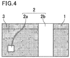
- the sheet 1 whose information is collected by the sheet information collection device 10 is described with reference to Fig. 4 .
- the clear windows 2a and 2b are formed in the lower left portion and the right portion on the sheet 1, respectively, as the transparent potions 2 capable of transmitting light.
- the clear window 2a has an island shape and is surrounded by an opaque portion 3.
- the clear window 2b has a belt shape and extends entirely from one edge to the other edge in the short edge direction (direction perpendicular to the transport direction) of the sheet 1.
- the sheet 1 may be of any type and may be, for example, a banknote, a gift voucher, a cheque, a document of value, or a card-like medium.
- the paper used for banknotes is usually paper made of vegetable fibers. Still, in order to improve the properties such as durability, water resistance, and security, paper made of synthetic fibers or a polymer sheet made of synthetic resin may be used. Banknotes made of polymer sheets are called polymer banknotes.
- the sheet 1 is preferably made of a polymer sheet because a synthetic resin is preferred as a material of the transparent portion 2.
- the sheet 1 may also be a sheet (hybrid sheet) whose transparent portion 2 is a polymer sheet and whose opaque portion 3 is paper made of vegetable fibers or synthetic fibers.
- the transparent portion 2 may partially include an optically variable element such as a rainbow hologram.
- the process executed by the controller 40 is described in more detail with reference to Figs. 5 .
- a case is described where the sheet 1, when being transported along the transport path 15, is laid with its long edges extending in the transport direction.
- the length in the main scanning direction of the optical line sensor 20 is designed to be about the same as the width of the transport path 15, which is greater than the short-edge width of the sheet 1.
- the optical line sensor 20 therefore can capture an image of the entire surface of the sheet 1 transported along the transport path 15.
- Fig. 5(a) the banknote is transported to the left.
- the data collector 41 starts to collect, i.e., read, the output data (output signals) from the optical line sensor 20 based on the data collection start signal to successively collect output data at the collection lines.
- the output data at one line include transmissive light data and reflected light data.
- the sheet 1 may be transported obliquely along the transport path 15.
- the data collector 41 collects output data also at a desired number of lines, e.g., a few lines, before the sheet 1 passes near the optical line sensor 20.
- the data collector 41 executes a predetermined process for the transmissive light data and reflected light data collected at each collection line, and stores the processed transmissive light data and reflected light data in the memory unit 50.
- the process executed by the data collector 41 is, for example, a process of averaging the output data of every few pixels.
- the resolution of an image at each collection line may set lower than the resolution of the optical line sensor 20 in the main scanning direction.
- the determiner 43 determines whether or not the sheet 1 is present at each collection line after a predetermined collection line (e.g., after several collection lines). Specifically, the determiner 43 references the transmission image data binarized by the binarizer 42, compares the number of pixels in the light blocking state at each collection line and a threshold 52 for medium presence determination stored in the memory unit 50, and determines that a collection line where the number of pixels in the light blocking state is equal to or greater than the threshold 52 for medium presence determination is in a sheet present state.
- a predetermined collection line e.g., after several collection lines.
- the determiner 43 determines whether or not the sheet 1 is absent at each collection line after the collection line determined to be in the sheet present state. Specifically, the determiner 43 references the transmission image data binarized by the binarizer 42, compares the number of pixels in the light blocking state at each collection line and a threshold 53 for media absence determination stored in the memory unit 50, and determines that a collection line where the number of pixels in the light blocking state is not greater than the threshold 53 for media absence determination is in a sheet absent state.
- the threshold 52 for medium presence determination and the threshold 53 for media absence determination are set such that a collection line corresponding to the island-shaped clear window 2a is determined to be in the sheet present state.
- a collection line corresponding to the clear window 2a can be designed such that it is not determined to be in the sheet absent state.
- the determiner 43 determines that a collection line having captured an image of the belt-shaped clear window 2b or a collection line having captured an image behind the rear edge of the sheet 1, i.e., only a background 4, are in the sheet absent state.
- the size or presence/absence of the island-shaped clear window 2a may be different for different types of the collection target sheets 1.
- the thresholds 52 for medium presence determination and the thresholds 53 for media absence determination which are set for different types of sheets 1 are stored in the memory unit 50, and the determiner 43 references the threshold 52 for medium presence determination and the threshold 53 for media absence determination corresponding to the type of the target sheet 1.
- the determiner 43 switches among the thresholds 52 for medium presence determination and the thresholds 53 for media absence determination to reference, based on the country of the recognition target and the type of the target sheet 1.
- the data collection stopper 44 counts the (total) number of collection lines determined to be in the sheet absent state and compares the number with one of two thresholds 54 and 55 for data collection stop determination stored in the memory unit 50. When the number of successive collection lines determined to be in the sheet absent state exceeds the comparison target threshold 54 or 55 for data collection stop determination, i.e., when the number becomes the comparison target threshold 54 or 55 for data collection stop determination plus one, the data collection stopper 44 determines that the rear edge of the sheet 1 is detected, and stops collection of output data from the optical line sensor 20 by the data collector 41.
- the threshold 54 for data collection stop determination is used for a region A (lines) before a predetermined specific line C
- the threshold 55 for data collection stop determination is used for a region B (lines) after the specific line C.
- the specific line C is set based on the position of the belt-shaped clear window 2b and the size of the collection target sheet 1 such that the clear window 2b does not overlap the region B after the specific line C.
- the threshold 54 for data collection stop determination is set for the region A corresponding to the front edge side of the sheet 1, and is greater than the number of lines corresponding to the width of the clear window 2b in the short edge direction (width of the clear window 2b in the long edge direction of the sheet 1). This configuration prevents the data collection stopper 44 from determining the clear window 2b as the rear edge of the sheet 1 even when collection lines are successively determined to be in the sheet absent state due to the clear window 2b.
- the threshold 54 for data collection stop determination may be a number corresponding to several tens of lines, for example.
- the threshold 55 for data collection stop determination is set for the region B corresponding to the rear edge side of the sheet 1, and is smaller than the other threshold 54.
- the data collection stopper 44 determines that the rear edge of the sheet 1 is detected when the (total) number of the collection lines exceeds the small threshold 55 for data collection stop determination, and stops collection of output data from the optical line sensor 20 by the data collector 41.
- the threshold 55 for data collection stop determination may be a number corresponding to several lines, for example.
- the data collection stopper 44 may switch between the thresholds 54 and 55 for data collection stop determination to reference, i.e., switch the threshold to reference from the threshold 54 for data collection stop determination to the threshold 55 for data collection stop determination, based on the length in the transport direction of a sheet 1 whose length in the transport direction is the shortest among all the types of collection target sheets 1.
- the specific line C is preferably set within the range that does not exceed the length in the transport direction of the sheet 1 whose length in the transport direction is the shortest.
- the size or presence/absence of the belt-shaped clear window 2b may be different for different types of the collection target sheet 1.
- the specific lines C which are set for different types of sheets 1 are stored in the memory unit 50, and the data collection stopper 44 references a specific line C corresponding to the type of the target sheet 1.
- the data collection stopper 44 preferably switches among the specific lines C to reference based on the country of the recognition target and the type of the target sheet 1.
- the thresholds 54 and 55 for data collection stop determination which are set for different types of sheets 1, are stored in the memory unit 50, and the data collection stopper 44 references the threshold 54 or 55 for data collection stop determination corresponding to the type of the target sheet 1.
- the data collection stopper 44 preferably switches between the thresholds 54 and 55 for data collection stop determination to reference, i.e., switch the threshold to reference from the threshold 54 for data collection stop determination to the threshold 55 for data collection stop determination, based on the country of the recognition target and the type of the target sheet 1.
- the sheet information collection device 10 may further include a detection portion for detecting the presence or absence of the transparent portion 2 such as the clear window 2b.
- the data collection stopper 44 may, after detection of the transparent portion 2, preferably the belt-shaped clear window 2b, switch between the thresholds 54 and 55 for data collection stop determination to reference, i.e., switch the threshold to reference from the threshold 54 for data collection stop determination to the threshold 55 for data collection stop determination.
- the data collection stopper 44 stops collection of output data from the optical line sensor 20 by the data collector 41 when the (total) number of collection lines reaches the collectable and storable maximum number of lines without the rear edge of the sheet 1 is detected.
- the maximum number of collection lines is set as appropriate according to the capacity of the memory unit 50 and other conditions, but is at least greater than the number of lines corresponding to the width in the long edge direction of the sheet 1.
- the data collection stopper 44 stops collection of output data from the optical line sensor 20 by the data collector 41 when no collection line is determined to be in the sheet present state before the number of collection lines reaches a predetermined number of lines.
- the predetermined number of lines can be set as appropriate within the range not exceeding the maximum number of collection lines, and may be, for example, several tens of lines.
- Embodiment 1 the features unique to the present embodiment are mainly described, and the same points as in Embodiment 1 are not elaborated upon below.
- the members having the same or similar function in the present embodiment and Embodiment 1 are provided with the same reference sign, and are not elaborated upon in the present embodiment.
- the present embodiment is substantially the same as Embodiment 1, except for the following points.
- the optical sensor used is a timing sensor.
- the optical sensor used is a timing sensor.
- FIG. 6(a) A case is described where, as shown in Fig. 6(a) , two light transmissive optical sensors 12a and 12b are disposed as the timing sensor 12 in the transport path 15, and the sheet 1, when being transported along the transport path 15, is laid with its long edges extending in the transport direction.
- the number of the light transmissive optical sensors is not particularly limited, and may be three or more.
- the optical sensor 12a is disposed at a position where the clear window 2b passes.
- the optical sensor 12b is disposed at a position where the clear windows 2a and 2b pass. This enables the optical sensor 12a to detect the clear window 2b, and the optical sensor 12b to detect the clear windows 2a and 2b.
- the banknote is transported to the left.
- Fig. 6(b) shows the output signals (detection signals), the upper ones from the optical sensor 12a and the lower ones from the optical sensor 12b.
- the horizontal axis represents the distance or position (collection point), while the vertical axis represents the level of transmission of light detected as a signal, with the higher level indicating the transmission level and the lower level indicating the blocking level.
- the clear window 2b passes the position of the optical sensor 12a as shown in Fig. 6(a) .
- the detection signal from the optical sensor 12a is at the blocking level at the collection point where the front edge of the sheet 1 reaches the position of the optical sensor 12a, the transmission level at the collection point where the front edge of the clear window 2b reaches the position of the optical sensor 12a, the blocking level at the collection point where the rear edge of the clear window 2b reaches the position of the optical sensor 12a, and the transmission level at the collection point where the rear edge of the sheet 1 reaches the position of the optical sensor 12a.
- the clear windows 2a and 2b pass the position of the optical sensor 12b as shown in Fig. 6(a) .
- the detection signal from the optical sensor 12b is at the blocking level at the collection point where the front edge of the sheet 1 reaches the position of the optical sensor 12b, the transmission level at the collection point where the front edge of the clear window 2a reaches the position of the optical sensor 12b, the blocking level at the collection point where the rear edge of the clear window 2a reaches the position of the optical sensor 12b, the transmission level at the collection point where the front edge of the clear window 2b reaches the position of the optical sensor 12b, the blocking level at the collection point where the rear edge of the clear window 2b reaches the position of the optical sensor 12b, and the transmission level at the collection point where the rear edge of the sheet 1 reaches the position of the optical sensor 12b.
- the data collector 41 starts to collect, i.e., read, the output data (output signals) from the optical sensors 12a and 12b based on the instruction from the sheet handling machine 100 to collect output data at each collection point.
- the data collector 41 stores the collected output data in the memory unit 50.
- the determiner 43 determines whether or not the sheet 1 is present at each collection point based on the collected output data from the optical sensors 12a and 12b. The determiner 43 determines that a collection point where the signal from at least one of the optical sensors 12a and 12b is at the blocking level is in the sheet present state, and determines that a collection point where all the signals from the optical sensors 12a and 12b are at the transmission level is in the sheet absent state.
- the data collection stopper 44 counts the (total) number of collection points determined to be in the sheet absent state and compares the number with the relatively large threshold 54 for data collection stop determination or the relatively small threshold 55 for data collection stop determination, which are stored in the memory unit 50. When the number of successive collection points determined to be in the sheet absent state exceeds the threshold 55 for data collection stop determination as in Embodiment 1, the data collection stopper 44 determines that the rear edge of the sheet 1 is detected, and stops collection of output data from the optical sensors 12a and 12b by the data collector 41.
- the sheet information collection device 10 of the embodiment includes the memory unit 50 and the data collection stopper 44.
- the memory unit 50 stores the thresholds for data collection stop determination set for the collection points.
- the data collection stopper 44 stops collection of transmissive light data by the data collector 41 when the determiner 43 determines that successive collection points in the transport direction are in the light transmission state and the number of the successive collection points is equal to or greater than one of the thresholds for data collection stop determination corresponding to the successive collection points.
- the threshold 55 for data collection stop determination corresponding to the rearmost edge region of the sheet is smaller than the thresholds for data collection stop determination corresponding to the other regions.
- the small threshold 55 can be used to detect the rear edge of the sheet 1, while a large threshold for data collection stop determination other than the threshold 55 can be used to detect a transparent portion.
- the sheet information collection device 10 can reduce extra transmissive light data to be collected after the detection of the rear edge of a sheet and reduce false detection of the rear edge of a sheet 1 having a transparent portion 2.
- the cases were described where the long edges of the transported sheet 1 extend in the transport direction. Yet, the short edges of the sheet 1 may extend in the transport direction.
- This embodiment is suitable for a sheet 1 that includes the transparent portion 2 from one edge to the other edge in the transport direction (long edge direction).
- the data collection stopper 44 may stop collection of output data from the optical line sensor 20 by the data collector 41 based on three or more thresholds for data collection stop determination set for three or more regions divided in the transport direction.
- the data collection stopper 44 may stop collection of output data from the optical line sensor 20 by the data collector 41 based on a threshold for data collection stop determination other than the smallest threshold 55 for data collection stop determination among the thresholds for data collection stop determination, or based on a threshold for data collection stop determination set for the region corresponding to the front edge side of the sheet 1.
- the present invention is therefore a useful technique to collect information of a sheet including a transparent portion.
Landscapes
- Physics & Mathematics (AREA)
- General Physics & Mathematics (AREA)
- Inspection Of Paper Currency And Valuable Securities (AREA)
Abstract
Description
- The present invention relates to sheet information collection devices and sheet information collection methods. More specifically, the present invention relates to a sheet information collection device suitable as a sheet recognition device configured to acquire information, including images, positions, and sizes, of sheets such as banknotes, gift vouchers, cheques, and card-like media; and a sheet information collection method.
- Sheets such as banknotes (printed money), gift vouchers, and cheques have a variety of security characteristics for anti-counterfeiting. For example, although paper made of vegetable fibers is usually used for sheets, paper made of synthetic fibers or a polymer sheet made of synthetic resin may be used in order to improve the properties such as durability, water resistance, and security. Banknotes made of polymer sheets are called polymer banknotes. Polymer banknotes having a clear window (transparent window) are difficult to counterfeit.
- For collection of information of a sheet, an optical sensor such as an optical line sensor is usually used. A clear window is a transparent portion transmitting light emitted from the optical sensor. A sheet having a transparent portion may therefore need to undergo different processes from a common sheet having no transparent portion.
- For example,
Patent Literature 1 discloses a sheet handling machine as a technique to prevent false detection of abnormal transport due to an island-shaped window formed in a banknote. The sheet handling machine stops operation of identifying the passage of the rear edge portion at a position corresponding to one transport path sensor during a preset period from a time point when the absence of a banknote is detected if the absence of the banknote is detected after judgement of passage of the banknote at the position corresponding to the one transport path sensor among a plurality of transport path sensors disposed along a transport path. - Patent Literature 1:
WO 2009/075015 - The size and/or position of a clear window of a sheet may be out of the scope of the specification of a conventional sheet handling machine. The sheet handling machine in such a case may falsely determine the clear window as the rear edge (the endmost edge) of the sheet, stop collection of transmissive light data from an optical sensor such as an optical line sensor, and falsely detect the portion of the sheet coming after the clear window as another sheet. For example, if a sheet has a wide, belt-shaped clear window from one edge to the other edge in its short edge direction, the technique disclosed in
Patent Literature 1 can cause false detection. - Actually, even if a clear window out of the scope of the specification is determined to be present, for example, the machine can be configured not to stop collection of transmissive light data as long as the width of the region in the transport direction is not greater than a predetermined threshold. Still, the machine would falsely determine the clear window as the rear edge of a sheet if the clear window extends beyond the threshold, stopping collection of transmissive light data. The threshold can simply be increased, but then the following disadvantages arise.
- The amount of collectable transmissive light data increases as the threshold increases. However, the capacity to store collected transmissive light data is usually limited, and thus the maximum length of a sheet collectable as data shortens.
- The distance required to detect chained sheets increases as the threshold increases. This raises the need to increase the distance between the transported sheets, slowing down the process.
- The time required to collect transmissive light data increases as the threshold increases. This lessens the time that can be spared for processes such as recognition of the type of a sheet, authentication of the sheet, and determination of the fitness of the sheet.
- In response to the above issues, an object of the present invention is to provide a sheet information collection device which can reduce extra data to be collected after the detection of the rear edge of a sheet and reduce false detection of the rear edge of a sheet having a transparent portion; and a sheet information collection method.
- A first aspect of the present invention is a sheet information collection device for collecting information of a sheet comprising a transparent portion, the device comprising: a transporter configured to transport the sheet; an optical sensor configured to scan the transported sheet in a transport direction and output transmissive light data acquired at a plurality of collection points set in the transport direction; a data collector configured to collect the transmissive light data from the optical sensor; a determiner configured to determine transmission or blocking of light at each collection point based on the transmissive light data; a recorder configured to store thresholds for data collection stop determination set for the collection points; and a data collection stopper configured to stop collection of the transmissive light data by the data collector when the determiner determines that light is transmitted at successive collection points in the transport direction and the number of the successive collection points is equal to or greater than one of the thresholds for data collection stop determination corresponding to the successive collection points, wherein among the thresholds for data collection stop determination, a threshold for data collection stop determination corresponding to a rearmost edge region of the sheet is smaller than the thresholds for data collection stop determination corresponding to another region.
- In the first aspect of the present invention, the optical sensor comprises an optical line sensor in which a plurality of pixels are disposed in a line in a width direction perpendicular to the transport direction.
- In the first aspect of the present invention, the recorder further stores a threshold for medium presence or absence determination, and the determiner determines transmission or blocking of light for transmissive light data successively acquired from the line of pixels based on the transmissive light data from the line of the pixels and the threshold for medium presence or absence determination.
- In the first aspect of the present invention, the transparent portion extends from one edge to the other edge in the width direction.
- In the first aspect of the present invention, the sheet information collection device is capable of collecting information of a plurality of types of sheets each including a transparent portion, and the data collection stopper switches among the thresholds for data collection stop determination based on a length in the transport direction of a sheet whose length in the transport direction is the shortest among the plurality of types of sheets.
- In the first aspect of the present invention, the data collection stopper switches among the thresholds for data collection stop determination after the transparent portion is detected.
- In the first aspect of the present invention, the sheet information collection device is capable of collecting information of a plurality of types of sheets each comprising a transparent portion, and the data collection stopper switches among the thresholds for data collection determination based on the type of the target sheet.
- In the first aspect of the present invention, the data collection stopper stops collection of the transmissive light data by the optical sensor based on a threshold for data collection stop determination corresponding to a region other than the rearmost edge region of the sheet among the plurality of thresholds for data collection stop determination.
- In the first aspect of the present invention, the data collection stopper stops collection of the transmissive light data by the optical sensor based on a threshold for data collection stop determination corresponding to a frontmost edge region of the sheet without switching among the thresholds for data collection stop determination.
- In the first aspect of the present invention, the sheet information collection device is capable of collecting information of a plurality of types of sheets each comprising a transparent portion, the recorder stores thresholds for data collection stop determination that are set for the respective types of the sheets, and the data collection stopper switches among the thresholds for data collection stop determination according to the type of the target sheet.
- A second aspect of the present invention is a sheet information collection method for collecting information of a sheet comprising a transparent portion, the method comprising: an output step of scanning the transported sheet in a transport direction and outputting transmissive light data at collection points set in the transport direction; a collection step of collecting transmissive light data from an optical sensor; a determination step of determining transmission or blocking of light at each collection point based on the transmissive light data; and a processing step of stopping collection of the transmissive light data in the data collection step based on thresholds for data collection stop determination set for the plurality of collection points, wherein the processing step comprises stopping collection of the transmissive light data in the data collection step when the determiner determines that light is transmitted at successive collection points in the transport direction and the number of the successive collection points is equal to or greater than one of the thresholds for data collection stop determination corresponding to the successive collection points, and among the thresholds for data collection stop determination, a threshold for data collection stop determination corresponding to a rearmost edge region of the sheet is smaller than the thresholds for data collection stop determination corresponding to the other regions.
- The sheet information collection device and the sheet information collection method according to the present invention can reduce extra data to be collected after the detection of the rear edge of a sheet and reduce false detection of the rear edge of a sheet having a transparent portion.
-
-
Fig. 1 is a schematic perspective view showing the external appearance of a sheet handling machine inEmbodiment 1. -
Figs. 2 are schematic views showing the configuration of a sheet information collection device ofEmbodiment 1; -
Fig. 2(a) is a view of the sheet information collection device from a side,Fig. 2(b) is a view of the upper part of the sheet information collection device from the lower side (from the Z-axis negative side), andFig. 2(c) is a view of the bottom part of the sheet information collection device from the upper side (from the Z-axis positive side). -
Fig. 3 is a functional block diagram of the sheet information collection device ofEmbodiment 1. -
Fig. 4 is a schematic plan view of a sheet which has a transparent portion and of which information is collected by the sheet information collection device ofEmbodiment 1. -
Figs. 5 are schematic views illustrating how the sheet information collection device ofEmbodiment 1 acquires information;Fig. 5(a) is a plan view showing the state where a sheet is transported along a transport path in which an optical line sensor is disposed, andFig. 5(b) is a transmission image obtained from the collected transmissive light data. -
Figs. 6 are schematic views illustrating how a sheet information collection device ofEmbodiment 2 acquires information;Fig. 6(a) is a plan view showing the state where a sheet is transported along a transport path in which optical sensors are disposed, andFig. 5(b) shows output data from the optical sensors. - Preferred embodiments of the sheet information collection device and the sheet information collection method according to the present invention are described in detail below with reference to the attached drawings. The sheet information collection device and the sheet information collection method according to the present invention can be utilized in a variety of fields. In the present embodiment, the sheet information collection device and the sheet information collection method according to the present invention are described based on an example in which these device and method are applied to a sheet recognition device utilizing sheet images for recognition of the type of a sheet, authentication of the sheet, and reading of symbols such as characters printed on the sheet, and to a sheet handling machine utilizing the sheet recognition device. In other words, the present embodiment is an embodiment of a sheet information collection device and a sheet information collection method which collect image information as the information of a sheet.
- As shown in
Fig. 1 , asheet handling machine 100 of the present embodiment is used to deposit and dispense sheets, and includes asheet inlet 101, asheet outlet 102, an operation/display unit 103, and a sheet recognition device (not illustrated). The operation/display unit 103 functions as an input device for inputting various pieces of information required to use thesheet handling machine 100, and also functions as an output device for outputting various pieces of information on the display. - The sheet recognition device in the present embodiment is used to capture an image of a banknote, a cheque, or a gift voucher, for example, inside the
sheet handling machine 100. The sheet recognition device in the present embodiment utilizes the image of the sheet captured by a sheet information collection device including an optical line sensor to recognize the type of the sheet (the denomination, in the case of a banknote), authenticate the sheet, determine the fitness of the sheet, or recognize the type of a document of value such as a cheque or a gift voucher. The sheet recognition device also utilizes the image of the sheet to read the serial number of a banknote or characters printed on a document of value, for example. - The method and device to deposit and dispense a sheet such as a banknote, the sheet recognition and character recognition utilizing images of sheets such as banknotes, and the device executing these processes can be conventional techniques. Thus, the detailed description thereof will not be elaborated upon here. The details of the sheet information collection device and the sheet information collection method for capturing an image of a sheet are described below.
- A sheet
information collection device 10 of the present embodiment includes, as shown inFigs. 2 , a sensor unit 11 including various sensors suited for recognition of asheet 1, the target of the process. The sensor unit 11 includes atiming sensor 12, alight source 13 for reflection and alight source 14 for transmission, which irradiate thesheet 1 with light such as infrared light or visible light, and anoptical line sensor 20 for acquiring optical image information of thesheet 1. The sensor unit 11 also includes rollers 31 disposed to transport thesheet 1 along thetransport path 15. The rollers 31 are driven by a drive unit such as a motor, which is not illustrated, and constitute a transporter 30. Each of the rollers 31 is rotated by the drive unit, so that thesheet 1 having entered thedevice 10 from the right side of the sensor unit 11 is transported inside the sensor unit 11 in the X-axis direction, and is ejected from the left side of the sensor unit 11. - The
timing sensor 12 detectssheets 1 successively transported into the sensor unit 11. Thetiming sensor 12 is usually a light-reflective or light-transmissive optical sensor, but may be a sensor mechanically detecting passage of asheet 1. - The sensor unit 11 may appropriately include an additional sensor as well as the
optical line sensor 20 and thetiming sensor 12. A suitable additional sensor is, for example, a thickness detection sensor for measuring the thickness of thesheet 1, a magnetic sensor for determining the magnetic characteristics of thesheet 1, or a fluorescence sensor for detecting the fluorescent ink portion of thesheet 1 by ultraviolet light irradiation. - The
optical line sensor 20 includes, as shown inFig. 2(a) , animage sensor 21 such as a CCD image sensor or a CMOS image sensor, a rod lens array (array of transparent tubular condenser lenses) 22 for leading light from thesheet 1 passing therebelow to theimage sensor 21, and alight guide 23. The bottom face of the sensor case is made of a transparent material and functions as ameasurement window 24. Light emitted from thelight guide 23 extending along therod lens array 22 travels through themeasurement window 24 and is reflected on thesheet 1. The reflected light travels through themeasurement window 24 and therod lens array 22 and is received by theimage sensor 21. - The
optical line sensor 20 has, as shown inFig. 2(b) , a linear shape extending in the Y-axis direction, and includes a plurality of photodetectors (pixels) 25 such as photo diodes, which is disposed in the Y-axis direction and constitutes theimage sensor 21. Thelight guide 23 and therod lens array 22 are disposed at positions suited for theimage sensor 21. As shown inFig. 2(b) , thelight source 13 for reflection, such as LEDs, is disposed adjacent to thelight guide 23. Light from thelight source 13 for reflection is incident on thelight guide 23. Thelight guide 23 is configured to emit incident light in the Z-axis negative direction while guiding the incident light in the Y-axis negative direction so as to emit light toward thesheet 1. Thelight source 13 for reflection is composed of members such as LEDs capable of emitting light rays in different wavelength ranges, for example, and can emit light in a selected wavelength range (e.g., green light or infrared light). - As shown in
Fig. 2(a) and Fig. 2(c) , below theoptical line sensor 20 are provided onelight guide 16 and thelight source 14 for transmission, such as LEDs, adjacent to thelight guide 16. Light from thelight source 14 for transmission is incident on thelight guide 16, and thelight guide 16 is configured to emit incident light in the Z-axis positive direction while guiding the incident light in the Y-axis negative direction so as to emit light toward thesheet 1. The top face of the case including thelight guide 16 is made of a transparent material and functions as anirradiation window 17. Light is emitted from thelight source 14 for transmission toward thesheet 1 through thelight guide 16 and theirradiation window 17. The light having passed through thesheet 1 is then received by theimage sensor 21 through themeasurement window 24 and therod lens array 22. Thelight source 14 for transmission is composed of members such as LEDs capable of emitting light rays in different wavelength ranges, for example, and can emit light in a selected wavelength range (e.g., green light or infrared light). - The
light guide 23 for guiding light from thelight source 13 for reflection and emit the light toward thesheet 1, thelight guide 16 for guiding light from thelight source 14 for transmission and emit the light toward thesheet 1, and theimage sensor 21 for receiving light reflected on thesheet 1 and light transmitted by thesheet 1 are disposed as shown inFig. 2(b) and Fig. 2(c) such that theoptical line sensor 20 can acquire a reflection image and a transmission image of the entire surface of thesheet 1 transported. Theoptical line sensor 20 scans the transportedsheet 1 in the transport direction to capture an image of the entire surface of thesheet 1. Specifically, theoptical line sensor 20 captures an image of theentire sheet 1 by successively capturing images of the entire linear imaging target regions of thesheet 1 in the Y-axis direction at the corresponding collection lines. In the present embodiment, a collection line corresponds to a collection point. - The sheet
information collection device 10 for controlling thelight source 13 for reflection, thelight source 14 for transmission, and theoptical line sensor 20 is described. As shown inFig. 3 , the sheetinformation collection device 10 includes acontroller 40 and amemory unit 50 as well as the configuration shown inFigs. 2 . Thecontroller 40 includes a logical device such as a field programmable gate array (FPGA) and includes adata collector 41, abinarizer 42, adeterminer 43, adata collection stopper 44, alight source controller 45, asensor controller 46, and amedia manager 47. To thecontroller 40 is input a system clock, which gives the basic frequency for operation of each portion, from a source out of thedevice 10. Thecontroller 40 utilizes the system clock to determine the operation timing and operation duration for each portion and execute the process. Thememory unit 50 is used to store data such as a variety of thresholds and to store reflection image data and transmission image data. The thresholds stored in thememory unit 50 are externally rewritable via a communication interface, which is not illustrated. - The
data collector 41 collects output data including reflected light data and transmissive light data from theoptical line sensor 20 at each collection line, executes a predetermined process for the collected output data, and stores the processed data as reflection image data and transmission image data in thememory unit 50. A reflection image and a transmission image of thesheet 1 are generated based on these data and used in processes such as denomination recognition. - The
binarizer 42 binarizes each pixel of the transmission image data generated by thedata collector 41, based on athreshold 51 for binarization stored in thememory unit 50. In other words, each pixel of the transmission image is converted into a blocking state (black) or a transmission state (white). Thereby, the transmission image of thesheet 1 is in the transmission state in the later-described regions ofclear windows - The
determiner 43 determines transmission or blocking of light at each collection line based on the transmission image data binarized by thebinarizer 42 to determine whether or not thesheet 1 is present at each collection line. - The
data collection stopper 44 stops collection of output data from theoptical line sensor 20 by thedata collector 41 when the later-described given conditions (1) to (3) hold. - The
light source controller 45 controls lighting of each of thelight sources light sources light sources - The
sensor controller 46 controls reception of light by theimage sensor 21 according to the timing when each of thelight sources light source controller 45. Thesensor controller 46 also controls thetiming sensor 12 and generate, based on the output signal from thetiming sensor 12, a data collection start signal for determining the timing when thedata collector 41 starts collection of output data from theoptical line sensor 20. - The
memory unit 50 includes memory devices such as volatile or non-volatile memory devices and hard disks, and is used to store various data necessary for the processes executed in the sheetinformation collection device 10. - The communication interface receives signals from the outside of the sheet
information collection device 10 and transmits signals from the sheetinformation collection device 10 to the outside. The communication interface can, for example, receive a signal from the outside to change the operation setting of thecontroller 40, update, add, and delete software programs and data stored in thememory unit 50, and output the information about thesheet 1 acquired by the sheetinformation collection device 10 and the determination result made by thedevice 10 to the outside. - The
sheet 1 whose information is collected by the sheetinformation collection device 10 is described with reference toFig. 4 . As shown inFig. 4 , theclear windows sheet 1, respectively, as thetransparent potions 2 capable of transmitting light. Theclear window 2a has an island shape and is surrounded by anopaque portion 3. Theclear window 2b has a belt shape and extends entirely from one edge to the other edge in the short edge direction (direction perpendicular to the transport direction) of thesheet 1. - The
sheet 1 may be of any type and may be, for example, a banknote, a gift voucher, a cheque, a document of value, or a card-like medium. The paper used for banknotes is usually paper made of vegetable fibers. Still, in order to improve the properties such as durability, water resistance, and security, paper made of synthetic fibers or a polymer sheet made of synthetic resin may be used. Banknotes made of polymer sheets are called polymer banknotes. In the present embodiment, thesheet 1 is preferably made of a polymer sheet because a synthetic resin is preferred as a material of thetransparent portion 2. Thesheet 1 may also be a sheet (hybrid sheet) whosetransparent portion 2 is a polymer sheet and whoseopaque portion 3 is paper made of vegetable fibers or synthetic fibers. Thetransparent portion 2 may partially include an optically variable element such as a rainbow hologram. - The process executed by the
controller 40 is described in more detail with reference toFigs. 5 . A case is described where thesheet 1, when being transported along thetransport path 15, is laid with its long edges extending in the transport direction. The length in the main scanning direction of theoptical line sensor 20 is designed to be about the same as the width of thetransport path 15, which is greater than the short-edge width of thesheet 1. Theoptical line sensor 20 therefore can capture an image of the entire surface of thesheet 1 transported along thetransport path 15. InFig. 5(a) , the banknote is transported to the left. - The
data collector 41 starts to collect, i.e., read, the output data (output signals) from theoptical line sensor 20 based on the data collection start signal to successively collect output data at the collection lines. The output data at one line include transmissive light data and reflected light data. Here, thesheet 1 may be transported obliquely along thetransport path 15. To properly generate an image of the front edge of thesheet 1 even in such a case, thedata collector 41 collects output data also at a desired number of lines, e.g., a few lines, before thesheet 1 passes near theoptical line sensor 20. Thedata collector 41 executes a predetermined process for the transmissive light data and reflected light data collected at each collection line, and stores the processed transmissive light data and reflected light data in thememory unit 50. The process executed by thedata collector 41 is, for example, a process of averaging the output data of every few pixels. The resolution of an image at each collection line may set lower than the resolution of theoptical line sensor 20 in the main scanning direction. - How to stop collection of output data from the
optical line sensor 20 by thedata collector 41 is described. In the present embodiment, collection of output data is stopped in any one of the following cases (1) to (3) . - (1) The case where the rear edge of the
sheet 1 is detected. - (2) The case where the number of collection lines reaches the maximum number of collection lines.
- (3) The case where no collection line is determined to be in the sheet present state before the number of collection lines reaches a predetermined number.
- First, the case (1) where the rear edge of the
sheet 1 is detected is described. - The
determiner 43 determines whether or not thesheet 1 is present at each collection line after a predetermined collection line (e.g., after several collection lines). Specifically, thedeterminer 43 references the transmission image data binarized by thebinarizer 42, compares the number of pixels in the light blocking state at each collection line and athreshold 52 for medium presence determination stored in thememory unit 50, and determines that a collection line where the number of pixels in the light blocking state is equal to or greater than thethreshold 52 for medium presence determination is in a sheet present state. - The
determiner 43 determines whether or not thesheet 1 is absent at each collection line after the collection line determined to be in the sheet present state. Specifically, thedeterminer 43 references the transmission image data binarized by thebinarizer 42, compares the number of pixels in the light blocking state at each collection line and athreshold 53 for media absence determination stored in thememory unit 50, and determines that a collection line where the number of pixels in the light blocking state is not greater than thethreshold 53 for media absence determination is in a sheet absent state. - The
threshold 52 for medium presence determination and thethreshold 53 for media absence determination are set such that a collection line corresponding to the island-shapedclear window 2a is determined to be in the sheet present state. Hence, a collection line corresponding to theclear window 2a can be designed such that it is not determined to be in the sheet absent state. Meanwhile, thedeterminer 43 determines that a collection line having captured an image of the belt-shapedclear window 2b or a collection line having captured an image behind the rear edge of thesheet 1, i.e., only abackground 4, are in the sheet absent state. - The size or presence/absence of the island-shaped
clear window 2a may be different for different types of thecollection target sheets 1. In such a case, preferably, thethresholds 52 for medium presence determination and thethresholds 53 for media absence determination, which are set for different types ofsheets 1, are stored in thememory unit 50, and thedeterminer 43 references thethreshold 52 for medium presence determination and thethreshold 53 for media absence determination corresponding to the type of thetarget sheet 1. In other words, thedeterminer 43 switches among thethresholds 52 for medium presence determination and thethresholds 53 for media absence determination to reference, based on the country of the recognition target and the type of thetarget sheet 1. - The
data collection stopper 44 counts the (total) number of collection lines determined to be in the sheet absent state and compares the number with one of two thresholds 54 and 55 for data collection stop determination stored in thememory unit 50. When the number of successive collection lines determined to be in the sheet absent state exceeds the comparison target threshold 54 or 55 for data collection stop determination, i.e., when the number becomes the comparison target threshold 54 or 55 for data collection stop determination plus one, thedata collection stopper 44 determines that the rear edge of thesheet 1 is detected, and stops collection of output data from theoptical line sensor 20 by thedata collector 41. - Which of the thresholds 54 and 55 for data collection stop determination should be the comparison target is determined based on the collection line determined to be in the sheet absent state. For example, the threshold 54 for data collection stop determination is used for a region A (lines) before a predetermined specific line C, and the threshold 55 for data collection stop determination is used for a region B (lines) after the specific line C. The specific line C is set based on the position of the belt-shaped
clear window 2b and the size of thecollection target sheet 1 such that theclear window 2b does not overlap the region B after the specific line C. The threshold 54 for data collection stop determination is set for the region A corresponding to the front edge side of thesheet 1, and is greater than the number of lines corresponding to the width of theclear window 2b in the short edge direction (width of theclear window 2b in the long edge direction of the sheet 1). This configuration prevents thedata collection stopper 44 from determining theclear window 2b as the rear edge of thesheet 1 even when collection lines are successively determined to be in the sheet absent state due to theclear window 2b. The threshold 54 for data collection stop determination may be a number corresponding to several tens of lines, for example. - The threshold 55 for data collection stop determination is set for the region B corresponding to the rear edge side of the
sheet 1, and is smaller than the other threshold 54. Thus, in the case where collection lines are successively determined to be in the sheet absent state due to passage of the rear edge of thesheet 1, thedata collection stopper 44 determines that the rear edge of thesheet 1 is detected when the (total) number of the collection lines exceeds the small threshold 55 for data collection stop determination, and stops collection of output data from theoptical line sensor 20 by thedata collector 41. The threshold 55 for data collection stop determination may be a number corresponding to several lines, for example. - The
data collection stopper 44 may switch between the thresholds 54 and 55 for data collection stop determination to reference, i.e., switch the threshold to reference from the threshold 54 for data collection stop determination to the threshold 55 for data collection stop determination, based on the length in the transport direction of asheet 1 whose length in the transport direction is the shortest among all the types ofcollection target sheets 1. Specifically, the specific line C is preferably set within the range that does not exceed the length in the transport direction of thesheet 1 whose length in the transport direction is the shortest. - The size or presence/absence of the belt-shaped
clear window 2b may be different for different types of thecollection target sheet 1. In such a case, preferably, the specific lines C, which are set for different types ofsheets 1, are stored in thememory unit 50, and thedata collection stopper 44 references a specific line C corresponding to the type of thetarget sheet 1. In other words, thedata collection stopper 44 preferably switches among the specific lines C to reference based on the country of the recognition target and the type of thetarget sheet 1. Also in this case, preferably, the thresholds 54 and 55 for data collection stop determination, which are set for different types ofsheets 1, are stored in thememory unit 50, and thedata collection stopper 44 references the threshold 54 or 55 for data collection stop determination corresponding to the type of thetarget sheet 1. In other words, thedata collection stopper 44 preferably switches between the thresholds 54 and 55 for data collection stop determination to reference, i.e., switch the threshold to reference from the threshold 54 for data collection stop determination to the threshold 55 for data collection stop determination, based on the country of the recognition target and the type of thetarget sheet 1. - The sheet
information collection device 10 may further include a detection portion for detecting the presence or absence of thetransparent portion 2 such as theclear window 2b. Thedata collection stopper 44 may, after detection of thetransparent portion 2, preferably the belt-shapedclear window 2b, switch between the thresholds 54 and 55 for data collection stop determination to reference, i.e., switch the threshold to reference from the threshold 54 for data collection stop determination to the threshold 55 for data collection stop determination. - The case (2) where the number of collection lines reaches the maximum number of collection lines is described.
- In this case, the
data collection stopper 44 stops collection of output data from theoptical line sensor 20 by thedata collector 41 when the (total) number of collection lines reaches the collectable and storable maximum number of lines without the rear edge of thesheet 1 is detected. The maximum number of collection lines is set as appropriate according to the capacity of thememory unit 50 and other conditions, but is at least greater than the number of lines corresponding to the width in the long edge direction of thesheet 1. - The case (3) where no collection line is determined to be in the sheet present state before the number of collection lines reaches a predetermined number is described.
- In this case, the
data collection stopper 44 stops collection of output data from theoptical line sensor 20 by thedata collector 41 when no collection line is determined to be in the sheet present state before the number of collection lines reaches a predetermined number of lines. The predetermined number of lines can be set as appropriate within the range not exceeding the maximum number of collection lines, and may be, for example, several tens of lines. - In the present embodiment, the features unique to the present embodiment are mainly described, and the same points as in
Embodiment 1 are not elaborated upon below. The members having the same or similar function in the present embodiment andEmbodiment 1 are provided with the same reference sign, and are not elaborated upon in the present embodiment. The present embodiment is substantially the same asEmbodiment 1, except for the following points. - In the present embodiment, a case is described where the optical sensor used is a timing sensor. In other words, in the present embodiment, how to collect information such as the position and size of a sheet as the sheet information is described.
- A case is described where, as shown in
Fig. 6(a) , two light transmissiveoptical sensors timing sensor 12 in thetransport path 15, and thesheet 1, when being transported along thetransport path 15, is laid with its long edges extending in the transport direction. The number of the light transmissive optical sensors is not particularly limited, and may be three or more. Theoptical sensor 12a is disposed at a position where theclear window 2b passes. Theoptical sensor 12b is disposed at a position where theclear windows optical sensor 12a to detect theclear window 2b, and theoptical sensor 12b to detect theclear windows Fig. 6(a) , the banknote is transported to the left. -
Fig. 6(b) shows the output signals (detection signals), the upper ones from theoptical sensor 12a and the lower ones from theoptical sensor 12b. In both graphs, the horizontal axis represents the distance or position (collection point), while the vertical axis represents the level of transmission of light detected as a signal, with the higher level indicating the transmission level and the lower level indicating the blocking level. - The
clear window 2b passes the position of theoptical sensor 12a as shown inFig. 6(a) . Thus, as shown inFig. 6(b) , the detection signal from theoptical sensor 12a is at the blocking level at the collection point where the front edge of thesheet 1 reaches the position of theoptical sensor 12a, the transmission level at the collection point where the front edge of theclear window 2b reaches the position of theoptical sensor 12a, the blocking level at the collection point where the rear edge of theclear window 2b reaches the position of theoptical sensor 12a, and the transmission level at the collection point where the rear edge of thesheet 1 reaches the position of theoptical sensor 12a. - The
clear windows optical sensor 12b as shown inFig. 6(a) . Thus, as shown inFig. 6(b) , the detection signal from theoptical sensor 12b is at the blocking level at the collection point where the front edge of thesheet 1 reaches the position of theoptical sensor 12b, the transmission level at the collection point where the front edge of theclear window 2a reaches the position of theoptical sensor 12b, the blocking level at the collection point where the rear edge of theclear window 2a reaches the position of theoptical sensor 12b, the transmission level at the collection point where the front edge of theclear window 2b reaches the position of theoptical sensor 12b, the blocking level at the collection point where the rear edge of theclear window 2b reaches the position of theoptical sensor 12b, and the transmission level at the collection point where the rear edge of thesheet 1 reaches the position of theoptical sensor 12b. - The
data collector 41 starts to collect, i.e., read, the output data (output signals) from theoptical sensors sheet handling machine 100 to collect output data at each collection point. Thedata collector 41 stores the collected output data in thememory unit 50. - The
determiner 43 determines whether or not thesheet 1 is present at each collection point based on the collected output data from theoptical sensors determiner 43 determines that a collection point where the signal from at least one of theoptical sensors optical sensors - The
data collection stopper 44 counts the (total) number of collection points determined to be in the sheet absent state and compares the number with the relatively large threshold 54 for data collection stop determination or the relatively small threshold 55 for data collection stop determination, which are stored in thememory unit 50. When the number of successive collection points determined to be in the sheet absent state exceeds the threshold 55 for data collection stop determination as inEmbodiment 1, thedata collection stopper 44 determines that the rear edge of thesheet 1 is detected, and stops collection of output data from theoptical sensors data collector 41. - As described above, the sheet
information collection device 10 of the embodiment includes thememory unit 50 and thedata collection stopper 44. Thememory unit 50 stores the thresholds for data collection stop determination set for the collection points. Thedata collection stopper 44 stops collection of transmissive light data by thedata collector 41 when thedeterminer 43 determines that successive collection points in the transport direction are in the light transmission state and the number of the successive collection points is equal to or greater than one of the thresholds for data collection stop determination corresponding to the successive collection points. Among the thresholds for data collection stop determination, the threshold 55 for data collection stop determination corresponding to the rearmost edge region of the sheet is smaller than the thresholds for data collection stop determination corresponding to the other regions. Hence, the small threshold 55 can be used to detect the rear edge of thesheet 1, while a large threshold for data collection stop determination other than the threshold 55 can be used to detect a transparent portion. Thereby, the sheetinformation collection device 10 can reduce extra transmissive light data to be collected after the detection of the rear edge of a sheet and reduce false detection of the rear edge of asheet 1 having atransparent portion 2. - Also, since extra transmissive light data to be collected can be reduced, the following effects (1) to (3) can be achieved even when a
sheet 1 including a region undetectable as a medium is present. - (1) Information of the
sheet 1 can be collected without shortening the maximum length in the transport direction of thesheet 1 whose transmissive light data can be collected, as compared with the conventional settings. - (2) Information of a
sheet 1 can be collected without lengthening the minimum detectable distance between chained sheets, as compared with the conventional settings. - (3) About the same time as in a conventional case can be spared for processes such as recognition of the type of a sheet, authentication of the sheet, and determination of the fitness of the sheet.
- Embodiments of the present invention have been described with reference to the drawings. The embodiment, however, is not intended to limit the scope of the present invention. The configurations of the embodiments may appropriately be combined or modified within the spirit of the present invention.
- In the above embodiments, the cases were described where the long edges of the transported
sheet 1 extend in the transport direction. Yet, the short edges of thesheet 1 may extend in the transport direction. This embodiment is suitable for asheet 1 that includes thetransparent portion 2 from one edge to the other edge in the transport direction (long edge direction). - In the above embodiments, the cases were described where the thresholds 54 and 55 for data collection stop determination were set for the respective two regions divided in the transport direction. Yet, the
data collection stopper 44 may stop collection of output data from theoptical line sensor 20 by thedata collector 41 based on three or more thresholds for data collection stop determination set for three or more regions divided in the transport direction. - In the above embodiments, the cases were described where collection of output data is stopped based on the smallest threshold 55 for data collection stop determination among the thresholds for data collection stop determination. Yet, the
data collection stopper 44 may stop collection of output data from theoptical line sensor 20 by thedata collector 41 based on a threshold for data collection stop determination other than the smallest threshold 55 for data collection stop determination among the thresholds for data collection stop determination, or based on a threshold for data collection stop determination set for the region corresponding to the front edge side of thesheet 1. - The present invention is therefore a useful technique to collect information of a sheet including a transparent portion.
-
- 1:
- sheet
- 2:
- transparent portion
- 2a, 2b:
- clear window
- 3:
- opaque portion
- 4:
- background
- 10:
- sheet information collection device
- 11:
- sensor unit
- 12:
- timing sensor
- 12a, 12b:
- optical sensor
- 13:
- light source for reflection
- 14:
- light source for transmission
- 15:
- transport path
- 16:
- light guide
- 17:
- irradiation window
- 20:
- optical line sensor
- 21:
- image sensor
- 22:
- rod lens array
- 23:
- light guide
- 24:
- measurement window
- 25:
- photodetector(pixel)
- 30:
- transporter
- 31:
- roller
- 40:
- controller
- 41:
- data collector
- 42:
- binarizer
- 43:
- determiner
- 44:
- data collection stopper
- 45:
- light source controller
- 46:
- sensor controller
- 47:
- media manager
- 50:
- memory unit
- 51:
- threshold for binarization
- 52:
- threshold for medium presence determination
- 53:
- threshold for medium absence determination
- 54, 55:
- threshold for data collection stop determination
- 100:
- sheet handling machine
- 101:
- sheet inlet
- 102:
- sheet outlet
- 103:
- operation/display unit
- A, B:
- region
- C:
- specific line
- N:
- maximum collection line
Claims (11)
- A sheet information collection device for collecting information of a sheet comprising a transparent portion, the device comprising:a transporter configured to transport the sheet;an optical sensor configured to scan the transported sheet in a transport direction and output transmissive light data acquired at a plurality of collection points set in the transport direction;a data collector configured to collect the transmissive light data from the optical sensor;a determiner configured to determine transmission or blocking of light at each collection point based on the transmissive light data;a recorder configured to store thresholds for data collection stop determination corresponding to the collection points; anda data collection stopper configured to stop collection of the transmissive light data by the data collector when the determiner determines that light is transmitted at successive collection points in the transport direction and the number of the successive collection points is equal to or greater than one of the thresholds for data collection stop determination corresponding to the successive collection points,wherein among the thresholds for data collection stop determination, a threshold for data collection stop determination corresponding to a rearmost edge region of the sheet is smaller than the thresholds for data collection stop determination corresponding to another region.
- The sheet information collection device according to claim 1,
wherein the optical sensor comprises an optical line sensor in which a plurality of pixels are disposed in a line in a width direction perpendicular to the transport direction. - The sheet information collection device according to claim 2,
wherein the recorder further stores a threshold for medium presence or absence determination, and
the determiner determines transmission or blocking of light for transmissive light data successively acquired from the line of pixels based on the transmissive light data from the line of the pixels and the threshold for medium presence or absence determination. - The sheet information collection device according to claim 2 or 3,
wherein the transparent portion extends from one edge to the other edge in the width direction. - The sheet information collection device according to any one of claims 1 to 4,
wherein the sheet information collection device is capable of collecting information of a plurality of types of sheets each comprising a transparent portion, and
the data collection stopper switches among the thresholds for data collection stop determination based on a length in the transport direction of a sheet whose length in the transport direction is the shortest among the plurality of types of sheets. - The sheet information collection device according to any one of claims 1 to 5,
wherein the data collection stopper switches among the thresholds for data collection stop determination after the transparent portion is detected. - The sheet information collection device according to any one of claims 1 to 6,
wherein the sheet information collection device is capable of collecting information of a plurality of types of sheets each comprising a transparent portion, and
the data collection stopper switches among the thresholds for data collection determination based on the type of the target sheet. - The sheet information collection device according to any one of claims 1 to 7,
wherein the data collection stopper stops collection of the transmissive light data by the optical sensor based on a threshold for data collection stop determination corresponding to a region other than the rearmost edge region of the sheet among the plurality of thresholds for data collection stop determination. - The sheet information collection device according to any one of claims 1 to 8,
wherein the data collection stopper stops collection of the transmissive light data by the optical sensor based on a threshold for data collection stop determination corresponding to a frontmost edge region of the sheet without switching among the thresholds for data collection stop determination. - The sheet information collection device according to any one of claims 1 to 9,
wherein the sheet information collection device is capable of collecting information of a plurality of types of sheets each comprising a transparent portion,
the recorder stores thresholds for data collection stop determination that are set for the respective types of sheets, and
the data collection stopper switches among the thresholds for data collection stop determination according to the type of the target sheet. - A sheet information collection method for collecting information of a sheet comprising a transparent portion, the method comprising:
an output step of scanning the transported sheet in a transport direction and outputting transmissive light data at a plurality of collection points set in the transport direction;
a collection step of collecting the transmissive light data from an optical sensor;
a determination step of determining transmission or blocking of light at each collection point based on the transmissive light data; and
a processing step of stopping collection of the transmissive light data in the data collection step based on thresholds for data collection stop determination set for the plurality of collection points,
wherein the processing step comprises stopping collection of the transmissive light data in the data collection step when the determiner determines that light is transmitted at successive collection points in the transport direction and the number of the successive collection points is equal to or greater than one of the thresholds for data collection stop determination corresponding to the successive collection points, and
among the thresholds for data collection stop determination, a threshold for data collection stop determination corresponding to a rearmost edge region of the sheet is smaller than the thresholds for data collection stop determination corresponding to the other regions.
Applications Claiming Priority (1)
| Application Number | Priority Date | Filing Date | Title |
|---|---|---|---|
| PCT/JP2016/065366 WO2017203614A1 (en) | 2016-05-24 | 2016-05-24 | Paper sheet information collection device and paper sheet information collection method |
Publications (3)
| Publication Number | Publication Date |
|---|---|
| EP3467794A1 true EP3467794A1 (en) | 2019-04-10 |
| EP3467794A4 EP3467794A4 (en) | 2020-02-05 |
| EP3467794B1 EP3467794B1 (en) | 2022-10-26 |
Family
ID=60412268
Family Applications (1)
| Application Number | Title | Priority Date | Filing Date |
|---|---|---|---|
| EP16903096.2A Active EP3467794B1 (en) | 2016-05-24 | 2016-05-24 | Paper sheet information collection device and paper sheet information collection method |
Country Status (3)
| Country | Link |
|---|---|
| EP (1) | EP3467794B1 (en) |
| AU (1) | AU2016407875B2 (en) |
| WO (1) | WO2017203614A1 (en) |
Families Citing this family (1)
| Publication number | Priority date | Publication date | Assignee | Title |
|---|---|---|---|---|
| JP7391668B2 (en) * | 2019-01-11 | 2023-12-05 | グローリー株式会社 | Image acquisition device, paper sheet processing device, banknote processing device, and image acquisition method |
Family Cites Families (5)
| Publication number | Priority date | Publication date | Assignee | Title |
|---|---|---|---|---|
| US8630475B2 (en) * | 2007-12-10 | 2014-01-14 | Glory Ltd. | Banknote handling machine and banknote handling method |
| US20100303332A1 (en) * | 2007-12-10 | 2010-12-02 | Glory Ltd. | Banknote handling machine and banknote handling method |
| JP2013191083A (en) * | 2012-03-14 | 2013-09-26 | Glory Ltd | Paper sheet feeding mechanism and paper sheet feeding method |
| JP6296805B2 (en) * | 2014-01-23 | 2018-03-20 | Ai Technology株式会社 | Detection device |
| JP6403391B2 (en) * | 2014-01-27 | 2018-10-10 | グローリー株式会社 | Banknote processing apparatus and banknote processing method |
-
2016
- 2016-05-24 EP EP16903096.2A patent/EP3467794B1/en active Active
- 2016-05-24 AU AU2016407875A patent/AU2016407875B2/en active Active
- 2016-05-24 WO PCT/JP2016/065366 patent/WO2017203614A1/en not_active Ceased
Also Published As
| Publication number | Publication date |
|---|---|
| EP3467794B1 (en) | 2022-10-26 |
| EP3467794A4 (en) | 2020-02-05 |
| AU2016407875B2 (en) | 2019-10-10 |
| AU2016407875A1 (en) | 2019-01-17 |
| WO2017203614A1 (en) | 2017-11-30 |
Similar Documents
| Publication | Publication Date | Title |
|---|---|---|
| US8483472B2 (en) | Paper sheet identifying device and paper sheet identifying method | |
| EP2660787A1 (en) | Defect categorisation in a digital image | |
| EP3598401B1 (en) | Paper sheet detection device, paper sheet processing apparatus, and paper sheet detection method | |
| WO2012083713A1 (en) | Banknote and finance bill identification method and device | |
| EP3723054B1 (en) | Banknote recognition unit, banknote handling device, and banknote recognition method | |
| KR100704851B1 (en) | Paper identification device and method | |
| JP4703403B2 (en) | Inspection device | |
| WO2004077366A1 (en) | Sheet identifying device and method | |
| EP3680867B1 (en) | Image acquisition device, sheet handling device, banknote handling device, and image acquisition method | |
| EP3467794B1 (en) | Paper sheet information collection device and paper sheet information collection method | |
| KR100656179B1 (en) | Sheet identifying device and method | |
| US11072507B2 (en) | Multi-purpose imaging system for active steering system, recognition and string detection system | |
| JP2018124857A (en) | Image capturing apparatus, coin-like medium processing machine, and image capturing method | |
| KR101397791B1 (en) | A media sensing apparatus and financial device | |
| AU2017299334A1 (en) | Paper sheet identification device and paper sheet identification method | |
| KR20160113878A (en) | Recognition apparatus for face value of bill and detection apparatus for counterfiet bill | |
| JP3897182B2 (en) | Microcode reader | |
| HK1224070A1 (en) | Paper sheet processing device | |
| JP2011113420A (en) | Image processor and image processing method |
Legal Events
| Date | Code | Title | Description |
|---|---|---|---|
| STAA | Information on the status of an ep patent application or granted ep patent |
Free format text: STATUS: THE INTERNATIONAL PUBLICATION HAS BEEN MADE |
|
| PUAI | Public reference made under article 153(3) epc to a published international application that has entered the european phase |
Free format text: ORIGINAL CODE: 0009012 |
|
| STAA | Information on the status of an ep patent application or granted ep patent |
Free format text: STATUS: REQUEST FOR EXAMINATION WAS MADE |
|
| 17P | Request for examination filed |
Effective date: 20181218 |
|
| AK | Designated contracting states |
Kind code of ref document: A1 Designated state(s): AL AT BE BG CH CY CZ DE DK EE ES FI FR GB GR HR HU IE IS IT LI LT LU LV MC MK MT NL NO PL PT RO RS SE SI SK SM TR |
|
| AX | Request for extension of the european patent |
Extension state: BA ME |
|
| DAV | Request for validation of the european patent (deleted) | ||
| DAX | Request for extension of the european patent (deleted) | ||
| A4 | Supplementary search report drawn up and despatched |
Effective date: 20200109 |
|
| RIC1 | Information provided on ipc code assigned before grant |
Ipc: G07D 11/235 20190101ALI20200102BHEP Ipc: G07D 3/00 20060101AFI20200102BHEP Ipc: G07D 9/00 20060101ALI20200102BHEP Ipc: G07D 7/00 20160101ALI20200102BHEP Ipc: G07D 7/185 20160101ALI20200102BHEP |
|
| GRAP | Despatch of communication of intention to grant a patent |
Free format text: ORIGINAL CODE: EPIDOSNIGR1 |
|
| STAA | Information on the status of an ep patent application or granted ep patent |
Free format text: STATUS: GRANT OF PATENT IS INTENDED |
|
| INTG | Intention to grant announced |
Effective date: 20220530 |
|
| GRAS | Grant fee paid |
Free format text: ORIGINAL CODE: EPIDOSNIGR3 |
|
| GRAA | (expected) grant |
Free format text: ORIGINAL CODE: 0009210 |
|
| STAA | Information on the status of an ep patent application or granted ep patent |
Free format text: STATUS: THE PATENT HAS BEEN GRANTED |
|
| AK | Designated contracting states |
Kind code of ref document: B1 Designated state(s): AL AT BE BG CH CY CZ DE DK EE ES FI FR GB GR HR HU IE IS IT LI LT LU LV MC MK MT NL NO PL PT RO RS SE SI SK SM TR |
|
| REG | Reference to a national code |
Ref country code: GB Ref legal event code: FG4D |
|
| REG | Reference to a national code |
Ref country code: CH Ref legal event code: EP |
|
| REG | Reference to a national code |
Ref country code: AT Ref legal event code: REF Ref document number: 1527618 Country of ref document: AT Kind code of ref document: T Effective date: 20221115 |
|
| REG | Reference to a national code |
Ref country code: DE Ref legal event code: R096 Ref document number: 602016075978 Country of ref document: DE |
|
| REG | Reference to a national code |
Ref country code: IE Ref legal event code: FG4D |
|
| REG | Reference to a national code |
Ref country code: LT Ref legal event code: MG9D |
|
| REG | Reference to a national code |
Ref country code: NL Ref legal event code: MP Effective date: 20221026 |
|
| REG | Reference to a national code |
Ref country code: AT Ref legal event code: MK05 Ref document number: 1527618 Country of ref document: AT Kind code of ref document: T Effective date: 20221026 |
|
| PG25 | Lapsed in a contracting state [announced via postgrant information from national office to epo] |
Ref country code: NL Free format text: LAPSE BECAUSE OF FAILURE TO SUBMIT A TRANSLATION OF THE DESCRIPTION OR TO PAY THE FEE WITHIN THE PRESCRIBED TIME-LIMIT Effective date: 20221026 |
|
| PG25 | Lapsed in a contracting state [announced via postgrant information from national office to epo] |
Ref country code: SE Free format text: LAPSE BECAUSE OF FAILURE TO SUBMIT A TRANSLATION OF THE DESCRIPTION OR TO PAY THE FEE WITHIN THE PRESCRIBED TIME-LIMIT Effective date: 20221026 Ref country code: PT Free format text: LAPSE BECAUSE OF FAILURE TO SUBMIT A TRANSLATION OF THE DESCRIPTION OR TO PAY THE FEE WITHIN THE PRESCRIBED TIME-LIMIT Effective date: 20230227 Ref country code: NO Free format text: LAPSE BECAUSE OF FAILURE TO SUBMIT A TRANSLATION OF THE DESCRIPTION OR TO PAY THE FEE WITHIN THE PRESCRIBED TIME-LIMIT Effective date: 20230126 Ref country code: LT Free format text: LAPSE BECAUSE OF FAILURE TO SUBMIT A TRANSLATION OF THE DESCRIPTION OR TO PAY THE FEE WITHIN THE PRESCRIBED TIME-LIMIT Effective date: 20221026 Ref country code: FI Free format text: LAPSE BECAUSE OF FAILURE TO SUBMIT A TRANSLATION OF THE DESCRIPTION OR TO PAY THE FEE WITHIN THE PRESCRIBED TIME-LIMIT Effective date: 20221026 Ref country code: ES Free format text: LAPSE BECAUSE OF FAILURE TO SUBMIT A TRANSLATION OF THE DESCRIPTION OR TO PAY THE FEE WITHIN THE PRESCRIBED TIME-LIMIT Effective date: 20221026 Ref country code: AT Free format text: LAPSE BECAUSE OF FAILURE TO SUBMIT A TRANSLATION OF THE DESCRIPTION OR TO PAY THE FEE WITHIN THE PRESCRIBED TIME-LIMIT Effective date: 20221026 |
|
| PG25 | Lapsed in a contracting state [announced via postgrant information from national office to epo] |
Ref country code: RS Free format text: LAPSE BECAUSE OF FAILURE TO SUBMIT A TRANSLATION OF THE DESCRIPTION OR TO PAY THE FEE WITHIN THE PRESCRIBED TIME-LIMIT Effective date: 20221026 Ref country code: PL Free format text: LAPSE BECAUSE OF FAILURE TO SUBMIT A TRANSLATION OF THE DESCRIPTION OR TO PAY THE FEE WITHIN THE PRESCRIBED TIME-LIMIT Effective date: 20221026 Ref country code: LV Free format text: LAPSE BECAUSE OF FAILURE TO SUBMIT A TRANSLATION OF THE DESCRIPTION OR TO PAY THE FEE WITHIN THE PRESCRIBED TIME-LIMIT Effective date: 20221026 Ref country code: IS Free format text: LAPSE BECAUSE OF FAILURE TO SUBMIT A TRANSLATION OF THE DESCRIPTION OR TO PAY THE FEE WITHIN THE PRESCRIBED TIME-LIMIT Effective date: 20230226 Ref country code: HR Free format text: LAPSE BECAUSE OF FAILURE TO SUBMIT A TRANSLATION OF THE DESCRIPTION OR TO PAY THE FEE WITHIN THE PRESCRIBED TIME-LIMIT Effective date: 20221026 Ref country code: GR Free format text: LAPSE BECAUSE OF FAILURE TO SUBMIT A TRANSLATION OF THE DESCRIPTION OR TO PAY THE FEE WITHIN THE PRESCRIBED TIME-LIMIT Effective date: 20230127 |
|
| P01 | Opt-out of the competence of the unified patent court (upc) registered |
Effective date: 20230531 |
|
| REG | Reference to a national code |
Ref country code: DE Ref legal event code: R097 Ref document number: 602016075978 Country of ref document: DE |
|
| PG25 | Lapsed in a contracting state [announced via postgrant information from national office to epo] |
Ref country code: SM Free format text: LAPSE BECAUSE OF FAILURE TO SUBMIT A TRANSLATION OF THE DESCRIPTION OR TO PAY THE FEE WITHIN THE PRESCRIBED TIME-LIMIT Effective date: 20221026 Ref country code: RO Free format text: LAPSE BECAUSE OF FAILURE TO SUBMIT A TRANSLATION OF THE DESCRIPTION OR TO PAY THE FEE WITHIN THE PRESCRIBED TIME-LIMIT Effective date: 20221026 Ref country code: EE Free format text: LAPSE BECAUSE OF FAILURE TO SUBMIT A TRANSLATION OF THE DESCRIPTION OR TO PAY THE FEE WITHIN THE PRESCRIBED TIME-LIMIT Effective date: 20221026 Ref country code: DK Free format text: LAPSE BECAUSE OF FAILURE TO SUBMIT A TRANSLATION OF THE DESCRIPTION OR TO PAY THE FEE WITHIN THE PRESCRIBED TIME-LIMIT Effective date: 20221026 Ref country code: CZ Free format text: LAPSE BECAUSE OF FAILURE TO SUBMIT A TRANSLATION OF THE DESCRIPTION OR TO PAY THE FEE WITHIN THE PRESCRIBED TIME-LIMIT Effective date: 20221026 |
|
| PG25 | Lapsed in a contracting state [announced via postgrant information from national office to epo] |
Ref country code: SK Free format text: LAPSE BECAUSE OF FAILURE TO SUBMIT A TRANSLATION OF THE DESCRIPTION OR TO PAY THE FEE WITHIN THE PRESCRIBED TIME-LIMIT Effective date: 20221026 Ref country code: AL Free format text: LAPSE BECAUSE OF FAILURE TO SUBMIT A TRANSLATION OF THE DESCRIPTION OR TO PAY THE FEE WITHIN THE PRESCRIBED TIME-LIMIT Effective date: 20221026 |
|
| PLBE | No opposition filed within time limit |
Free format text: ORIGINAL CODE: 0009261 |
|
| STAA | Information on the status of an ep patent application or granted ep patent |
Free format text: STATUS: NO OPPOSITION FILED WITHIN TIME LIMIT |
|
| 26N | No opposition filed |
Effective date: 20230727 |
|
| PG25 | Lapsed in a contracting state [announced via postgrant information from national office to epo] |
Ref country code: SI Free format text: LAPSE BECAUSE OF FAILURE TO SUBMIT A TRANSLATION OF THE DESCRIPTION OR TO PAY THE FEE WITHIN THE PRESCRIBED TIME-LIMIT Effective date: 20221026 |
|
| REG | Reference to a national code |
Ref country code: CH Ref legal event code: PL |
|
| PG25 | Lapsed in a contracting state [announced via postgrant information from national office to epo] |
Ref country code: MC Free format text: LAPSE BECAUSE OF FAILURE TO SUBMIT A TRANSLATION OF THE DESCRIPTION OR TO PAY THE FEE WITHIN THE PRESCRIBED TIME-LIMIT Effective date: 20221026 |
|
| REG | Reference to a national code |
Ref country code: BE Ref legal event code: MM Effective date: 20230531 |
|
| PG25 | Lapsed in a contracting state [announced via postgrant information from national office to epo] |
Ref country code: MC Free format text: LAPSE BECAUSE OF FAILURE TO SUBMIT A TRANSLATION OF THE DESCRIPTION OR TO PAY THE FEE WITHIN THE PRESCRIBED TIME-LIMIT Effective date: 20221026 Ref country code: LU Free format text: LAPSE BECAUSE OF NON-PAYMENT OF DUE FEES Effective date: 20230524 Ref country code: LI Free format text: LAPSE BECAUSE OF NON-PAYMENT OF DUE FEES Effective date: 20230531 Ref country code: CH Free format text: LAPSE BECAUSE OF NON-PAYMENT OF DUE FEES Effective date: 20230531 |
|
| REG | Reference to a national code |
Ref country code: IE Ref legal event code: MM4A |
|
| PG25 | Lapsed in a contracting state [announced via postgrant information from national office to epo] |
Ref country code: IE Free format text: LAPSE BECAUSE OF NON-PAYMENT OF DUE FEES Effective date: 20230524 |
|
| PG25 | Lapsed in a contracting state [announced via postgrant information from national office to epo] |
Ref country code: IE Free format text: LAPSE BECAUSE OF NON-PAYMENT OF DUE FEES Effective date: 20230524 |
|
| PG25 | Lapsed in a contracting state [announced via postgrant information from national office to epo] |
Ref country code: IT Free format text: LAPSE BECAUSE OF FAILURE TO SUBMIT A TRANSLATION OF THE DESCRIPTION OR TO PAY THE FEE WITHIN THE PRESCRIBED TIME-LIMIT Effective date: 20221026 Ref country code: FR Free format text: LAPSE BECAUSE OF NON-PAYMENT OF DUE FEES Effective date: 20230531 Ref country code: BE Free format text: LAPSE BECAUSE OF NON-PAYMENT OF DUE FEES Effective date: 20230531 |
|
| PG25 | Lapsed in a contracting state [announced via postgrant information from national office to epo] |
Ref country code: BG Free format text: LAPSE BECAUSE OF FAILURE TO SUBMIT A TRANSLATION OF THE DESCRIPTION OR TO PAY THE FEE WITHIN THE PRESCRIBED TIME-LIMIT Effective date: 20221026 |
|
| PG25 | Lapsed in a contracting state [announced via postgrant information from national office to epo] |
Ref country code: BG Free format text: LAPSE BECAUSE OF FAILURE TO SUBMIT A TRANSLATION OF THE DESCRIPTION OR TO PAY THE FEE WITHIN THE PRESCRIBED TIME-LIMIT Effective date: 20221026 |
|
| PGFP | Annual fee paid to national office [announced via postgrant information from national office to epo] |
Ref country code: DE Payment date: 20250521 Year of fee payment: 10 |
|
| PGFP | Annual fee paid to national office [announced via postgrant information from national office to epo] |
Ref country code: GB Payment date: 20250527 Year of fee payment: 10 |
|
| PG25 | Lapsed in a contracting state [announced via postgrant information from national office to epo] |
Ref country code: CY Free format text: LAPSE BECAUSE OF FAILURE TO SUBMIT A TRANSLATION OF THE DESCRIPTION OR TO PAY THE FEE WITHIN THE PRESCRIBED TIME-LIMIT; INVALID AB INITIO Effective date: 20160524 |
|
| PG25 | Lapsed in a contracting state [announced via postgrant information from national office to epo] |
Ref country code: HU Free format text: LAPSE BECAUSE OF FAILURE TO SUBMIT A TRANSLATION OF THE DESCRIPTION OR TO PAY THE FEE WITHIN THE PRESCRIBED TIME-LIMIT; INVALID AB INITIO Effective date: 20160524 |
|
| PG25 | Lapsed in a contracting state [announced via postgrant information from national office to epo] |
Ref country code: TR Free format text: LAPSE BECAUSE OF FAILURE TO SUBMIT A TRANSLATION OF THE DESCRIPTION OR TO PAY THE FEE WITHIN THE PRESCRIBED TIME-LIMIT Effective date: 20221026 |