EP3467783A1 - Method and device for hole filling of a point cloud - Google Patents
Method and device for hole filling of a point cloud Download PDFInfo
- Publication number
- EP3467783A1 EP3467783A1 EP17306346.2A EP17306346A EP3467783A1 EP 3467783 A1 EP3467783 A1 EP 3467783A1 EP 17306346 A EP17306346 A EP 17306346A EP 3467783 A1 EP3467783 A1 EP 3467783A1
- Authority
- EP
- European Patent Office
- Prior art keywords
- boundary
- point
- point cloud
- points
- hole filling
- Prior art date
- Legal status (The legal status is an assumption and is not a legal conclusion. Google has not performed a legal analysis and makes no representation as to the accuracy of the status listed.)
- Withdrawn
Links
Images

Classifications
-
- G—PHYSICS
- G06—COMPUTING OR CALCULATING; COUNTING
- G06T—IMAGE DATA PROCESSING OR GENERATION, IN GENERAL
- G06T17/00—Three-dimensional [3D] modelling for computer graphics
-
- G—PHYSICS
- G06—COMPUTING OR CALCULATING; COUNTING
- G06T—IMAGE DATA PROCESSING OR GENERATION, IN GENERAL
- G06T7/00—Image analysis
- G06T7/90—Determination of colour characteristics
-
- G—PHYSICS
- G06—COMPUTING OR CALCULATING; COUNTING
- G06T—IMAGE DATA PROCESSING OR GENERATION, IN GENERAL
- G06T2207/00—Indexing scheme for image analysis or image enhancement
- G06T2207/10—Image acquisition modality
- G06T2207/10028—Range image; Depth image; 3D point clouds
-
- G—PHYSICS
- G06—COMPUTING OR CALCULATING; COUNTING
- G06T—IMAGE DATA PROCESSING OR GENERATION, IN GENERAL
- G06T2210/00—Indexing scheme for image generation or computer graphics
- G06T2210/56—Particle system, point based geometry or rendering
Definitions
- the present disclosure generally relates to the field of point cloud data sources that represent 3D objects. More particularly, it deals with the post-processing of point clouds.
- the disclosure concerns a method for hole filling of a point cloud and a corresponding device. It also concerns methods for encoding and decoding a point cloud and corresponding encoder and decoder. It further concerns a computer program implementing the hole filling method of the invention.
- a point cloud consists in a set of points usually intended to represent the external surface of a 3D object but also more complex geometries like hair, fur that may not be represented efficiently by other data format like meshes.
- Each point is defined by its 3D spatial location (x, y and z coordinates in the 3D space), i.e. geometry information, and possibly by other associated attributes, which typically include the color information represented in the RGB or YUV or any other color coordinate system. Other attributes may include a transparency, a reflectance, etc.
- Geometry can be regarded as one of the attribute data. In the rest of this disclosure, both geometry and other attribute data are considered as attributes of points.
- a colored point cloud is considered, i.e. a set of 6-component points (X, Y, Z, R, G, B) or equivalently (X, Y, Z, Y, U, V) where (X,Y,Z) defines the spatial location of a point in a 3D space and (R,G,B) or (Y,U,V) defines a color of this point.
- Colored point clouds may be static or dynamic depending on whether or not the point cloud evolves with respect to time. It should be noticed that in case of a dynamic point cloud, the number of points is not constant but, on the contrary, generally evolves with time. A dynamic point cloud is thus a time-ordered list of sets of points.
- Point cloud data sources are found in many applications. Important applications relying on huge point cloud data sources can be found in geographic information systems, robotics, medical tomography and scientific visualization.
- Scanned 3D point clouds often have thousands of points and occupy large amounts of storage space. Additionally, they can be generated at a high rate when captured live from 3D scanners, increasing the data rate even further. Therefore, point cloud compression is critical for efficient networked distribution and storage.
- the prior art works on point cloud hole filling are mainly based on boundary point detection, close boundary loop extraction, and boundary loop filling.
- Boundary point detection is performed by projecting the neighboring points of each point of the point cloud to its local tangent plane. Those points whose projected neighboring points cannot form a whole circle are regarded as boundary points. Then, boundary loop extraction is performed by tracing neighboring detected boundary points. When the current tracing boundary meets the boundary point where the current tracing starts, a close boundary loop is found. The resultant closed boundary loops are then filled by adding points in the middle of the boundary loops.
- boundary point detection needs to be accurate. If some of boundary points are missed or some points are wrongly detected as boundary points during the detection step or otherwise, boundary loop cannot be closed.
- boundary point detection is usually difficult, as no connectivity between points is available. Indeed, the calculation of the local tangent plane is dependent on the choice of the neighborhood. As there is no connectivity information available, it is difficult to define the correct neighborhood of each point in the point cloud. Therefore, boundary point detection is usually difficult.
- boundary loop filling step is usually dependent on complex operations like polynomial fitting, surface reconstruction and triangulation.
- point cloud hole filling techniques are not suitable for use-cases that require low complexity, such as on-the-fly point cloud rendering and point cloud decoding.
- the present disclosure proposes a solution for improving the situation.
- the present disclosure provides a method for hole filling of a point cloud having at least one hole, comprising:
- the method of the present disclosure enables a significant reduction of the complexity of the prior art hole filling techniques by using a plane insertion operation. Also, as the present solution does not require to extract closed boundary point loops, accurate boundary point detection is not needed, making the hole filling method of the present disclosure more robust than the prior art solutions.
- a point of the point cloud is detected as a boundary point using an angle criterion. This technique for detecting boundary points is described in section 4.2 of the article of Bendels et al. "Detecting holes in point set surfaces", The Journal of WSCG, Vol. 14, WSCG 2006, January 30-Februrary 3, 2006 . Its accuracy is not optimal but it is sufficient for the hole filling method of the present disclosure that does not need to extract precise and close boundary point loops.
- a point of the point cloud is detected as a boundary point if the largest angle gap between two consecutive local neighbors of the point is larger than a first threshold and the largest angle gap between two consecutive further neighbors of the point is smaller than a second threshold.
- Local neighbors means here close neighbors, for instance distance-1 neighbors, while further neighbors are located further, for instance distance-10 neighbors.
- the second threshold condition allows to avoid detecting false boundary points.
- the first threshold is equal to 60 degrees and the second threshold is equal to 120 degrees.
- the angle gap between consecutive neighbors is the angle gap between the projections of these neighbors on a tangent plane of the point.
- At least one boundary point group is defined for each boundary region and each boundary point group is covered by one plane.
- the method comprises determining an attribute of each new point.
- the attribute is the color
- the attribute is determined by interpolation from nearby points of the point cloud.
- the interpolation is performed in the (R,G,B) color space.
- the interpolation is performed in the (Y,U,V) color space.
- the present disclosure also provides a hole filling device for hole filling a point cloud having at least one hole, comprising:
- the modules of the hole filling device are implemented by one or more processors.
- the present disclosure provides a method for coding a point cloud representing a 3D object, comprising a hole filling post-processing according to the present disclosure.
- the present disclosure also provides a method for decoding a point cloud representing a 3D object, comprising a hole filling post-processing according to the present disclosure.
- the present disclosure also provides an encoder comprising the hole filling device of the present disclosure.
- the present disclosure further provides a decoder comprising the hole filling device of the present disclosure.
- the methods according to the disclosure may be implemented in software on a programmable apparatus. They may be implemented solely in hardware or in software, or in a combination thereof.
- a carrier medium may comprise a storage medium such as a floppy disk, a CD-ROM, a hard disk drive, a magnetic tape device or a solid state memory device and the like.
- the disclosure thus provides a computer-readable program comprising computer-executable instructions to enable a computer to perform the hole filling method of the invention.
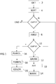
- the diagram of figure 1 illustrates an example of the general algorithm for such computer program.
- the method starts at step 2 by a detection of the boundary points of the point cloud.
- a point of the point cloud is detected as a boundary point using preferably an angle criterion.
- a point P of the point cloud with the largest angle gap g between two consecutive neighbors of P projected on the local tangent plane of P larger than a first threshold T1 are considered as possible boundary points.
- a possible value of T1 is 60 degrees.
- the distance-S neighborhood Neigh ( x Neigh , y Neigh , z Neigh ) of a point P ( x p ,y p ,z p ) is defined by Neigh x Neigh y Neigh z Neigh
- the eigenvectors and corresponding eigenvalues of C are calculated. After being normalized and sorted in decreasing order of eigenvalues, the three eigenvectors are chosen as the X, Y and Z axes of a local coordinate system at the point P.
- the origin of the local coordinate system is M.
- Each S-neighbor N i is projected to the XOY plane of the local coordinate system as follows.
- N i Proj x ′ , y ′ , 0 is the result of projecting N i to the XOY plane of the local coordinate system.
- the matrix Transf includes a 3x3 rotation matrix R and a translation vector T.
- the vector p represents the rotation which makes the X axis of the world coordinate system to be aligned with the X axis of the local coordinate system.
- the vector q represents the rotation which makes the Y axis of the world coordinate system, after being rotated by p , to be aligned with the Y axis of the local coordinate system.
- q ⁇ cos ⁇ Rotat Y 2 + vx Rotat Y sin ⁇ Rotat Y 2 ⁇ i + vy Rotat Y sin ⁇ Rotat Y 2 ⁇ j + vz Rotat Y sin ⁇ Rotat Y 2 ⁇ k .
- the difference of ⁇ i of two adjacent N i in the list of all N i is calculated. If the largest difference, or gap, noted g is larger than a first threshold T1, then P is considered as a possible boundary point.
- the further neighbors of P are defined as all the points falling on the surface of the cube or sphere which is centered at P and with scale or diameter 2*S'.
- S' is preferably dependent on the scale of the hole to be filled, for instance of S' may be chosen equal to 10.
- T' the largest gap between two consecutive projected further neighbors is computed. Only points having g' smaller than a second threshold T' are considered as boundary points. A possible value of T' is 120 degrees.
- all the detected boundary points are sorted into a queue, named all_boundary_point_queue, such that the number of their distance-N neighbors that are also boundary points is increasing.
- N A possible value of N is 2. Indeed, the boundary points with more neighbors, which are also boundary points, are most likely to be located on a big hole.
- step 6 it is checked if all_boundary_point_queue is empty. If yes, the process ends.
- boundary_region_current is created and set as empty in the beginning.
- step 10 it is checked whether or not current_boundary_point_queue is empty. If this is the case, the process continues to step 16 described later on.
- boundary_point_cur the boundary point at the front of current_boundary_point_queue
- boundary_point_cur is added to boundary_region_current.
- step 10 the process goes to step 10 where it is checked if current_boundary_point_queue is empty.
- step 16 the process goes to step 16 at which boundary_region_current is covered with several planes in order to approximate the underlying surface around each boundary region.
- the covering process starts from a boundary point, noted as boundary-point-start, belonging to boundary_region_current which has not been marked as covered to construct a boundary point group noted as boundary-point-group.
- boundary-point-start is added to boundary-point-group and boundary-point-start is marked as covered and checked.
- a mean point MEAN and a normal NORMAL are calculated by applying Principal Component Analysis (PCA) on boundary_point_start and said its distance-N neighbors of boundary_point start which belong to boundary_region_current and have not been marked as covered and checked.
- PCA Principal Component Analysis
- the distance-N neighbors of boundary-point-start which belong to boundary_region_current, which have not been marked as covered and as checked, and which their distances to PLN is less than a user defined threshold THRES_PLANE are added to boundary-point-group and marked as covered and checked.
- THRES_PLANE 2.0.
- the distance-N neighbors of boundary-point-start which belong to boundary_region_current have not been marked as covered and as checked, and their distances to PLN is bigger than a user defined threshold THRES_PLANE are marked as checked and are not added to boundary-point-group.
- the associated planes are transformed to new points to be included in the point cloud.
- potential new points to be included in the point cloud are determined as follows for each of the determined planes at step 18.
- the associated plane is defined by applying PCA on all the boundary points belonging to the boundary point group. All the boundary points belonging to the current boundary point group and their distance N' neighbors are projected on the plane associated to the current boundary point group. Then, on the plane, inside a bounding box of all projected points, the unoccupied points constitute one group of the potential new points. A possible value of N' is 4.
- each group of the potential new points is then projected to the world coordinate system by applying the reverse process of projecting points to local coordinate system described before. Overlapping points are merged together. After merging, the left new points are added to the input point cloud.
- step 20 for each new point P New inserted in the point cloud at step 18, its color is determined by interpolating the color attribute of its nearby existing and newly added points of the point cloud.
- the color interpolation may be performed either in the (R,G,B) or in the (Y,U,V) space.
- the same formula can be written in the (R,G,B) space by replacing (Y,U,V) by (R,G,B).
- Figure 3 is a block diagram of an exemplary embodiment of an encoder 30 implementing the encoding method of a 3D point cloud of the present disclosure.
- the encoder 30 includes one or more processors and a memory 32.
- the encoder 30 comprises a coding module 34 configured to encode an input 3D point cloud into a bit stream.
- the encoder 30 also comprises a hole filling device 36 comprising:
- a bus 46 provides a communication path between various elements of the encoder 30.
- Other point-to-point interconnection options e.g. non-bus architecture are also feasible.
- Figure 4 is a block diagram of an exemplary embodiment of a decoder 50 implementing the decoder method of the present disclosure.
- the decoder 50 includes one or more processors and a memory 52.
- the decoder 50 comprises a decoding module 54 configured to decode an input bit stream into a 3D point cloud.
- the decoder 50 also comprises the hole filling device 36 described above.
- a bus 56 provides a communication path between various elements of the decoder 50.
- Other point-to-point interconnection options e.g. non-bus architecture are also feasible.
Landscapes
- Engineering & Computer Science (AREA)
- Physics & Mathematics (AREA)
- General Physics & Mathematics (AREA)
- Theoretical Computer Science (AREA)
- Computer Graphics (AREA)
- Geometry (AREA)
- Software Systems (AREA)
- Computer Vision & Pattern Recognition (AREA)
- Image Processing (AREA)
- Image Generation (AREA)
Abstract
This method for hole filling of a point cloud having at least one hole comprises:
- detecting (2) boundary points of the point cloud;
- grouping (12) the detected boundary points in boundary regions based on their spatial adjacency;
- covering (16) each boundary region with at least one plane; and
- inserting (18) new points in the point cloud using the planes covering the boundary regions.
- detecting (2) boundary points of the point cloud;
- grouping (12) the detected boundary points in boundary regions based on their spatial adjacency;
- covering (16) each boundary region with at least one plane; and
- inserting (18) new points in the point cloud using the planes covering the boundary regions.
Description
- The present disclosure generally relates to the field of point cloud data sources that represent 3D objects.
More particularly, it deals with the post-processing of point clouds.
Thus, the disclosure concerns a method for hole filling of a point cloud and a corresponding device. It also concerns methods for encoding and decoding a point cloud and corresponding encoder and decoder. It further concerns a computer program implementing the hole filling method of the invention. - The approaches described in this section could be pursued, but are not necessarily approaches that have been previously conceived or pursued. Therefore, unless otherwise indicated herein, the approaches described in this section are not prior art to the claims in this application and are not admitted to be prior art by inclusion in this section.
- A point cloud consists in a set of points usually intended to represent the external surface of a 3D object but also more complex geometries like hair, fur that may not be represented efficiently by other data format like meshes. Each point is defined by its 3D spatial location (x, y and z coordinates in the 3D space), i.e. geometry information, and possibly by other associated attributes, which typically include the color information represented in the RGB or YUV or any other color coordinate system. Other attributes may include a transparency, a reflectance, etc. Geometry can be regarded as one of the attribute data. In the rest of this disclosure, both geometry and other attribute data are considered as attributes of points.
- In the following, a colored point cloud is considered, i.e. a set of 6-component points (X, Y, Z, R, G, B) or equivalently (X, Y, Z, Y, U, V) where (X,Y,Z) defines the spatial location of a point in a 3D space and (R,G,B) or (Y,U,V) defines a color of this point.
- Colored point clouds may be static or dynamic depending on whether or not the point cloud evolves with respect to time. It should be noticed that in case of a dynamic point cloud, the number of points is not constant but, on the contrary, generally evolves with time. A dynamic point cloud is thus a time-ordered list of sets of points.
- Point cloud data sources are found in many applications. Important applications relying on huge point cloud data sources can be found in geographic information systems, robotics, medical tomography and scientific visualization.
- Beyond these applications that are more industrial and scientifically oriented, the rise in popularity of inexpensive 3D scanners based on time of flight or other depth sensing technologies, 3D capturing on mobile devices and the rise of cloud based 3D printing are creating a huge demand for large scale interoperable compressed 3D point cloud storage and transmission data formats in the consumer market.
- Scanned 3D point clouds often have thousands of points and occupy large amounts of storage space. Additionally, they can be generated at a high rate when captured live from 3D scanners, increasing the data rate even further. Therefore, point cloud compression is critical for efficient networked distribution and storage.
- During the capturing of a point cloud, due to surface reflectance properties, occlusions and accessibility limitations, certain areas of the object may be not sampled leading to holes in the resulting point cloud. These holes represent significative missing parts of the 3D point cloud.
- Thus, a hole filling technique must be used in order to complete the point cloud.
- The prior art works on point cloud hole filling are mainly based on boundary point detection, close boundary loop extraction, and boundary loop filling.
- Boundary point detection is performed by projecting the neighboring points of each point of the point cloud to its local tangent plane. Those points whose projected neighboring points cannot form a whole circle are regarded as boundary points. Then, boundary loop extraction is performed by tracing neighboring detected boundary points. When the current tracing boundary meets the boundary point where the current tracing starts, a close boundary loop is found. The resultant closed boundary loops are then filled by adding points in the middle of the boundary loops.
- In the prior art, only the closed boundary point loops are regarded as boundaries and will be filled. Therefore, the boundary point detection needs to be accurate. If some of boundary points are missed or some points are wrongly detected as boundary points during the detection step or otherwise, boundary loop cannot be closed.
- However, boundary point detection is usually difficult, as no connectivity between points is available. Indeed, the calculation of the local tangent plane is dependent on the choice of the neighborhood. As there is no connectivity information available, it is difficult to define the correct neighborhood of each point in the point cloud. Therefore, boundary point detection is usually difficult.
- Also, the boundary loop filling step is usually dependent on complex operations like polynomial fitting, surface reconstruction and triangulation.
- Thus, the prior art point cloud hole filling techniques are not suitable for use-cases that require low complexity, such as on-the-fly point cloud rendering and point cloud decoding.
- The present disclosure proposes a solution for improving the situation.
- Accordingly, the present disclosure provides a method for hole filling of a point cloud having at least one hole, comprising:
- detecting boundary points of the point cloud;
- grouping the detected boundary points in boundary regions based on their spatial adjacency;
- covering each boundary region with at least one plane; and
- inserting new points in the point cloud using the planes covering the boundary regions.
- Thus, the method of the present disclosure enables a significant reduction of the complexity of the prior art hole filling techniques by using a plane insertion operation. Also, as the present solution does not require to extract closed boundary point loops, accurate boundary point detection is not needed, making the hole filling method of the present disclosure more robust than the prior art solutions.
According to an embodiment, a point of the point cloud is detected as a boundary point using an angle criterion.
This technique for detecting boundary points is described in section 4.2 of the article of Bendels et al. "Detecting holes in point set surfaces", The Journal of WSCG, Vol. 14, WSCG 2006, January 30-Februrary 3, 2006. Its accuracy is not optimal but it is sufficient for the hole filling method of the present disclosure that does not need to extract precise and close boundary point loops. - Advantageously, a point of the point cloud is detected as a boundary point if the largest angle gap between two consecutive local neighbors of the point is larger than a first threshold and the largest angle gap between two consecutive further neighbors of the point is smaller than a second threshold.
- Local neighbors means here close neighbors, for instance distance-1 neighbors, while further neighbors are located further, for instance distance-10 neighbors. The second threshold condition allows to avoid detecting false boundary points.
- For example, the first threshold is equal to 60 degrees and the second threshold is equal to 120 degrees.
- According to an embodiment, the angle gap between consecutive neighbors is the angle gap between the projections of these neighbors on a tangent plane of the point.
- Advantageously, at least one boundary point group is defined for each boundary region and each boundary point group is covered by one plane.
- Advantageously, the method comprises determining an attribute of each new point.
- According to an embodiment, the attribute is the color.
- Advantageously, the attribute is determined by interpolation from nearby points of the point cloud.
- According to an embodiment, the interpolation is performed in the (R,G,B) color space.
- According to another embodiment, the interpolation is performed in the (Y,U,V) color space.
- The present disclosure also provides a hole filling device for hole filling a point cloud having at least one hole, comprising:
- a detection module configured to detect boundary points of the point cloud;
- a grouping module configured to group the detected boundary points in boundary regions based on their spatial adjacency;
- a covering module configured to cover each boundary region with at least one plane; and
- an insertion module configured to insert new points in the point cloud using the planes covering the boundary regions.
- Advantageously, the modules of the hole filling device are implemented by one or more processors.
- According to another aspect, the present disclosure provides a method for coding a point cloud representing a 3D object, comprising a hole filling post-processing according to the present disclosure.
- The present disclosure also provides a method for decoding a point cloud representing a 3D object, comprising a hole filling post-processing according to the present disclosure.
- The present disclosure also provides an encoder comprising the hole filling device of the present disclosure.
- The present disclosure further provides a decoder comprising the hole filling device of the present disclosure.
- The methods according to the disclosure may be implemented in software on a programmable apparatus. They may be implemented solely in hardware or in software, or in a combination thereof.
- Since these methods can be implemented in software, they can be embodied as computer readable code for provision to a programmable apparatus on any suitable carrier medium. A carrier medium may comprise a storage medium such as a floppy disk, a CD-ROM, a hard disk drive, a magnetic tape device or a solid state memory device and the like.
- The disclosure thus provides a computer-readable program comprising computer-executable instructions to enable a computer to perform the hole filling method of the invention.
- The diagram of
figure 1 illustrates an example of the general algorithm for such computer program. - The present invention is illustrated by way of examples, and not by way of limitation, in the figures of the accompanying drawings, in which like reference numerals refer to similar elements and in which:
-
Figure 1 is a flowchart showing the steps of hole filling of a point cloud, according to an embodiment of the present disclosure; -
Figure 2 represents a transformation matrix used for the detection of boundary points, according to an embodiment of the present disclosure; -
Figure 3 is a schematic view illustrating an encoder, according to an embodiment of the disclosure; and -
Figure 4 is a schematic view illustrating a decoder, according to an embodiment of the disclosure. - The method for hole filling of a 3D point cloud according to an embodiment of the present disclosure is illustrated in the flowchart of
Figure 1 . - The method starts at
step 2 by a detection of the boundary points of the point cloud. - A point of the point cloud is detected as a boundary point using preferably an angle criterion.
Thus, a point P of the point cloud with the largest angle gap g between two consecutive neighbors of P projected on the local tangent plane of P larger than a first threshold T1 are considered as possible boundary points. A possible value of T1 is 60 degrees. According to one embodiment, for each point P, a mean point M and a covariance matrix C are calculated using the distance-S neighborhood, {Ni }, of P, where S=1 for example, using the following:

- Here, the distance-S neighborhood Neigh ( xNeigh , yNeigh, zNeigh ) of a point P(xp,yp,zp ) is defined by

- Then, the eigenvectors and corresponding eigenvalues of C are calculated. After being normalized and sorted in decreasing order of eigenvalues, the three eigenvectors are chosen as the X, Y and Z axes of a local coordinate system at the point P.
- The origin of the local coordinate system is M.
- Let's denote the three sorted and normalized eigenvectors as


- Each S-neighbor Ni is projected to the XOY plane of the local coordinate system as follows.
- Firstly, N'i (x', y', z'), the coordinates of Ni represented in the local coordinate system, are calculated by N'i (x', y', z') = Transf * Ni , where Transf is a 4x4 matrix represented in
Figure 2 . Then,
- As it appears in
Figure 2 , the matrix Transf includes a 3x3 rotation matrix R and a translation vector T. - According to an embodiment, R is calculated by

q andp are two quaternions. - The vector
p represents the rotation which makes the X axis of the world coordinate system to be aligned with the X axis of the local coordinate system. -
p is determined by the rotation axis

p =
- The vector
q represents the rotation which makes the Y axis of the world coordinate system, after being rotated byp , to be aligned with the Y axis of the local coordinate system. -
q is determined by the rotation axis


- The vector T is calculated by T = M.
- Secondly, the angle ∝ i between


- Thirdly, all the neighbors Ni are sorted by the angle ∝ i into a list.
- Fourthly, the difference of ∝ i of two adjacent Ni in the list of all Ni is calculated. If the largest difference, or gap, noted g is larger than a first threshold T1, then P is considered as a possible boundary point.
- Then for each possible boundary point P of the point cloud, the following process is carried out.
- This process starts by finding further neighbors of the point P. The further neighbors of P are defined as all the points falling on the surface of the cube or sphere which is centered at P and with scale or
diameter 2*S'.
- The choice of the value of S' is preferably dependent on the scale of the hole to be filled, for instance of S' may be chosen equal to 10.
- Then, all the further neighbors of P are projected on the tangent plane of P and sorted according to their angles around P.
- Then, the largest gap g' between two consecutive projected further neighbors is computed. Only points having g' smaller than a second threshold T' are considered as boundary points. A possible value of T' is 120 degrees.
- Then, at
step 4, all the detected boundary points are sorted into a queue, named all_boundary_point_queue, such that the number of their distance-N neighbors that are also boundary points is increasing. A possible value of N is 2. Indeed, the boundary points with more neighbors, which are also boundary points, are most likely to be located on a big hole. - At
step 6, it is checked if all_boundary_point_queue is empty. If yes, the process ends. - Otherwise, the first boundary point is popped out from all boundary_point_queue and is considered at
step 8. A queue associated to this boundary point, named current_boundary_point_queue, is created. Said first boundary point is marked as visited and pushed into current_boundary_point_queue. A new boundary point region, boundary_region_current, is created and set as empty in the beginning. - At
step 10, it is checked whether or not current_boundary_point_queue is empty. If this is the case, the process continues to step 16 described later on. - If current_boundary_point_queue is not empty, the boundary point at the front of current_boundary_point_queue, named boundary_point_cur, is popped out from current_boundary_point_queue.
- At
step 12, boundary_point_cur is added to boundary_region_current.. - At
step 13, the distance-N neighbors of boundary_point_cur which are also boundary points and not marked as visited yet are added to current_boundary_point_queue. - Then, at
step 14, said distance-N neighbors of boundary_point_cur which are also boundary points and not marked as visited yet are marked as visited. - Then, the process goes to step 10 where it is checked if current_boundary_point_queue is empty.
- If the queue is empty, the process goes to step 16 at which boundary_region_current is covered with several planes in order to approximate the underlying surface around each boundary region.
- Firstly, the covering process starts from a boundary point, noted as boundary-point-start, belonging to boundary_region_current which has not been marked as covered to construct a boundary point group noted as boundary-point-group. The boundary-point-start is added to boundary-point-group and boundary-point-start is marked as covered and checked.
- Secondly, distance-N neighbors of boundary-point-start which belong to boundary_region_current and have not been marked as covered and checked are considered. Then a mean point MEAN and a normal NORMAL are calculated by applying Principal Component Analysis (PCA) on boundary_point_start and said its distance-N neighbors of boundary_point start which belong to boundary_region_current and have not been marked as covered and checked.
- Then, a new plane PLN is defined by NORMAL*(P-MEAN) = 0, where * is vector dot product.
- Thirdly, the distance of each of the distance-N neighbors of boundary-point-start, which belong to boundary_region_current and have not been marked as covered and checked, noted as boundary-point-neigh, to PLN is calculated as NORMAL*(boundary-point_neigh -MEAN).
- Fourthly, on one side the distance-N neighbors of boundary-point-start which belong to boundary_region_current, which have not been marked as covered and as checked, and which their distances to PLN is less than a user defined threshold THRES_PLANE are added to boundary-point-group and marked as covered and checked. For example, THRES_PLANE=2.0. On the otherside, the distance-N neighbors of boundary-point-start which belong to boundary_region_current, have not been marked as covered and as checked, and their distances to PLN is bigger than a user defined threshold THRES_PLANE are marked as checked and are not added to boundary-point-group.
- This process is repeated by:
- firstly, calculating a new plane PLN_NEW by applying PCA on the points belonging to boundary-point-group and the distance-N neighbors of the points belonging to boundary-point-group, which belong to boundary_region_current and have not been marked as covered and checked;
- secondly, calculating the distances of each of the distance-N neighbors of the points belonging to boundary-point-group, which belong to boundary_region_current and have not been marked as covered and checked to PLN_NEW;
- thirdly, adding to boundary-point-group and marking as covered and checked the distance-N neighbors of the points belonging to boundary-point-group which belong to boundary_region_current that have not been marked as covered, have not been marked as checked, and their distances to PLN_NEW is less than THRES_PLANE;
- fourthly, marking as covered and checked the distance-N neighbors of the points belonging to boundary-point-group which belong to boundary_region_current that have not been marked as covered, have not been marked as checked, and their distances to PLN_NEW is bigger than THRES_PLANE.
- The above process is repeated until all the points belonging to boundary_region_current are marked as checked.
- Then, it is checked whether all the boundary points belonging to boundary_region_current are marked as covered. If yes, the process goes to step 18. If not, all points belonging to boundary_region_current are marked as unchecked. Then, the plane growing process as described above is repeated starting from a boundary point belonging to boundary_region_current that has not been marked as covered and a new boundary-point-group is defined. The plane growing and new boundary point group creation process are repeated until all the boundary points belonging to boundary_region_current are marked as covered.
- At
step 18, for each boundary region, the associated planes are transformed to new points to be included in the point cloud. - Firstly, potential new points to be included in the point cloud are determined as follows for each of the determined planes at
step 18. - For each boundary point group, the associated plane is defined by applying PCA on all the boundary points belonging to the boundary point group. All the boundary points belonging to the current boundary point group and their distance N' neighbors are projected on the plane associated to the current boundary point group. Then, on the plane, inside a bounding box of all projected points, the unoccupied points constitute one group of the potential new points. A possible value of N' is 4.
- Secondly, each group of the potential new points is then projected to the world coordinate system by applying the reverse process of projecting points to local coordinate system described before. Overlapping points are merged together. After merging, the left new points are added to the input point cloud.
- Then, at
step 20, for each new point PNew inserted in the point cloud atstep 18, its color is determined by interpolating the color attribute of its nearby existing and newly added points of the point cloud. - The color interpolation may be performed either in the (R,G,B) or in the (Y,U,V) space.
- For instance, the interpolation advantageously uses the following formula expressed in the (Y,U,V) space:

The same formula can be written in the (R,G,B) space by replacing (Y,U,V) by (R,G,B). -
Figure 3 is a block diagram of an exemplary embodiment of anencoder 30 implementing the encoding method of a 3D point cloud of the present disclosure. - Advantageously, the
encoder 30 includes one or more processors and amemory 32. - The
encoder 30 comprises acoding module 34 configured to encode an input 3D point cloud into a bit stream. - According to the present disclosure, the
encoder 30 also comprises ahole filling device 36 comprising: - a
detection module 38 configured to detect boundary points of the point cloud; - a
grouping module 40 configured to group the detected boundary points in boundary regions based on their spatial adjacency; - a
covering module 42 configured to cover each boundary region with at least one plane; and - an
insertion module 44 configured to insert new points in the point cloud using the planes covering the boundary regions. - According to the represented embodiment, a
bus 46 provides a communication path between various elements of theencoder 30. Other point-to-point interconnection options (e.g. non-bus architecture) are also feasible. -
Figure 4 is a block diagram of an exemplary embodiment of adecoder 50 implementing the decoder method of the present disclosure. - Advantageously, the
decoder 50 includes one or more processors and amemory 52. - The
decoder 50 comprises adecoding module 54 configured to decode an input bit stream into a 3D point cloud. - According to the present disclosure, the
decoder 50 also comprises thehole filling device 36 described above. - According to the represented embodiment, a
bus 56 provides a communication path between various elements of thedecoder 50. Other point-to-point interconnection options (e.g. non-bus architecture) are also feasible. - While there has been illustrated and described what are presently considered to be the preferred embodiments of the present invention, it will be understood by those skilled in the art that various other modifications may be made, and equivalents may be substituted, without departing from the true scope of the present invention. Additionally, many modifications may be made to adapt a particular situation to the teachings of the present invention without departing from the central inventive concept described herein.
- Furthermore, an embodiment of the present invention may not include all of the features described above. Therefore, it is intended that the present invention is not limited to the particular embodiments disclosed, but that the invention includes all embodiments falling within the scope of the appended claims.
- Expressions such as "comprise", "include", "incorporate", "contain", "is" and "have" are to be construed in a non-exclusive manner when interpreting the description and its associated claims, namely construed to allow for other items or components which are not explicitly defined also to be present. Reference to the singular is also to be construed to be a reference to the plural and vice versa.
- A person skilled in the art will readily appreciate that various parameters disclosed in the description may be modified and that various embodiments disclosed and/or claimed may be combined without departing from the scope of the invention.
Claims (15)
- Method for hole filling of a point cloud having at least one hole, comprising:- detecting (2) boundary points of the point cloud;- grouping (12) the detected boundary points in boundary regions based on their spatial adjacency;- covering (16) each boundary region with at least one plane; and- inserting (18) new points in the point cloud using the planes covering the boundary regions.
- Method of claim 1, wherein a point of the point cloud is detected as a boundary point using an angle criterion.
- Method of claim 2, wherein a point of the point cloud is detected as a boundary point if the largest angle gap between two consecutive local neighbors of the point is larger than a first threshold and the largest angle gap between two consecutive further neighbors of the point is smaller than a second threshold.
- Method of claim 3, wherein the angle gap between consecutive neighbors is the angle gap between the projections of these neighbors on a tangent plane of the point.
- Method of any one of claims 1 to 4, wherein at least one boundary point group is defined for each boundary region and each boundary point group is covered by one plane.
- Method of any one of claims 1 to 5, comprising determining (20) an attribute of each new point.
- Method of claim 6, wherein the attribute is the color.
- Method of claim 6 or 7, wherein the attribute is determined by interpolation from nearby points of the point cloud.
- Method of claim 8, wherein the interpolation is performed in the (R,G,B) or in the (Y,U,V) color space.
- Hole filling device (36) for hole filling a point cloud having at least one hole, comprising:- a detection module (38) configured to detect boundary points of the point cloud;- a grouping module (40) configured to group the detected boundary points in boundary regions based on their spatial adjacency;- a covering module (42) configured to cover each boundary region with at least one plane; and- an insertion module (44) configured to insert new points in the point cloud using the planes covering the boundary regions.
- Method for coding a point cloud representing a 3D object, comprising a hole filling post-processing according to any one of claims 1 to 9.
- Method for decoding a point cloud representing a 3D object, comprising a hole filling post-processing according to any one of claims 1 to 9.
- Encoder (30) comprising the hole filling device (36) of claim 10.
- Decoder (50) comprising the hole filling device (36) of claim 10.
- Computer-readable program comprising computer-executable instructions to enable a computer to perform the hole filling method of any one of claims 1 to 9.
Priority Applications (5)
| Application Number | Priority Date | Filing Date | Title |
|---|---|---|---|
| EP17306346.2A EP3467783A1 (en) | 2017-10-06 | 2017-10-06 | Method and device for hole filling of a point cloud |
| EP18786921.9A EP3692507B1 (en) | 2017-10-06 | 2018-10-02 | Method and device for hole filling of a point cloud |
| US16/753,766 US11532120B2 (en) | 2017-10-06 | 2018-10-02 | Method and device for hole filling of a point cloud |
| PCT/US2018/053931 WO2019070679A1 (en) | 2017-10-06 | 2018-10-02 | Method and device for hole filling of a point cloud |
| CN201880070075.3A CN111295694A (en) | 2017-10-06 | 2018-10-02 | Method and device for hole filling of point cloud |
Applications Claiming Priority (1)
| Application Number | Priority Date | Filing Date | Title |
|---|---|---|---|
| EP17306346.2A EP3467783A1 (en) | 2017-10-06 | 2017-10-06 | Method and device for hole filling of a point cloud |
Publications (1)
| Publication Number | Publication Date |
|---|---|
| EP3467783A1 true EP3467783A1 (en) | 2019-04-10 |
Family
ID=60182499
Family Applications (2)
| Application Number | Title | Priority Date | Filing Date |
|---|---|---|---|
| EP17306346.2A Withdrawn EP3467783A1 (en) | 2017-10-06 | 2017-10-06 | Method and device for hole filling of a point cloud |
| EP18786921.9A Active EP3692507B1 (en) | 2017-10-06 | 2018-10-02 | Method and device for hole filling of a point cloud |
Family Applications After (1)
| Application Number | Title | Priority Date | Filing Date |
|---|---|---|---|
| EP18786921.9A Active EP3692507B1 (en) | 2017-10-06 | 2018-10-02 | Method and device for hole filling of a point cloud |
Country Status (4)
| Country | Link |
|---|---|
| US (1) | US11532120B2 (en) |
| EP (2) | EP3467783A1 (en) |
| CN (1) | CN111295694A (en) |
| WO (1) | WO2019070679A1 (en) |
Cited By (1)
| Publication number | Priority date | Publication date | Assignee | Title |
|---|---|---|---|---|
| CN113223189A (en) * | 2021-05-31 | 2021-08-06 | 北京航空航天大学 | Method for repairing holes of three-dimensional point cloud model for grabbing object by mechanical arm and fitting regular body |
Families Citing this family (5)
| Publication number | Priority date | Publication date | Assignee | Title |
|---|---|---|---|---|
| US12217518B2 (en) | 2020-11-26 | 2025-02-04 | Samsung Electronics Co., Ltd. | Method and apparatus with object detection |
| CN114022617B (en) * | 2021-11-18 | 2024-04-30 | 中国科学院长春光学精密机械与物理研究所 | Method for identifying hole boundaries in scattered point clouds |
| KR102670285B1 (en) * | 2021-12-21 | 2024-05-30 | 세메스 주식회사 | Mobile robot for transporting article in manufacturing facility and article transport system including the same |
| CN117078701B (en) * | 2023-08-25 | 2025-08-05 | 北京数字绿土科技股份有限公司 | A point cloud plane segmentation processing method with optimized region growing |
| CN120807958B (en) * | 2025-07-09 | 2025-12-23 | 曹妃甸港集团股份有限公司 | AI-based methods and systems for detecting the edges of pallets |
Family Cites Families (7)
| Publication number | Priority date | Publication date | Assignee | Title |
|---|---|---|---|---|
| CN102436654B (en) | 2011-09-02 | 2013-07-10 | 清华大学 | Adaptive segmentation method of building point cloud |
| CN104344795A (en) | 2013-07-24 | 2015-02-11 | 鸿富锦精密工业(深圳)有限公司 | Point cloud profile measuring system and method |
| CN104634242A (en) | 2013-11-12 | 2015-05-20 | 鸿富锦精密工业(深圳)有限公司 | Point adding system and method of probe |
| CN105788000A (en) | 2014-12-16 | 2016-07-20 | 富泰华工业(深圳)有限公司 | Grid hole patching method and system |
| US11297346B2 (en) * | 2016-05-28 | 2022-04-05 | Microsoft Technology Licensing, Llc | Motion-compensated compression of dynamic voxelized point clouds |
| CN106056614A (en) | 2016-06-03 | 2016-10-26 | 武汉大学 | Building segmentation and contour line extraction method of ground laser point cloud data |
| CN106384386B (en) | 2016-10-08 | 2019-05-03 | 广州市香港科大霍英东研究院 | Mesh processing method and system and 3D reconstruction method and system in LOD model generation |
-
2017
- 2017-10-06 EP EP17306346.2A patent/EP3467783A1/en not_active Withdrawn
-
2018
- 2018-10-02 EP EP18786921.9A patent/EP3692507B1/en active Active
- 2018-10-02 WO PCT/US2018/053931 patent/WO2019070679A1/en not_active Ceased
- 2018-10-02 CN CN201880070075.3A patent/CN111295694A/en active Pending
- 2018-10-02 US US16/753,766 patent/US11532120B2/en active Active
Non-Patent Citations (4)
| Title |
|---|
| "Network and Parallel Computing", vol. 2768, 1 January 2003, SPRINGER INTERNATIONAL PUBLISHING, Cham, ISBN: 978-3-642-35622-3, ISSN: 0302-9743, article PAVEL CHALMOVIANSKÝ ET AL: "Filling Holes in Point Clouds", pages: 196 - 212, XP055431959, 032548, DOI: 10.1007/978-3-540-39422-8_14 * |
| BENDELS ET AL.: "Detecting holes in point set surfaces", THE JOURNAL OF WSCG, vol. 14, 30 January 2006 (2006-01-30) |
| GERHARD H BENDELS ET AL: "Detecting holes in point set surfaces", 1 January 2006 (2006-01-01), XP055432108, Retrieved from the Internet <URL:http://citeseerx.ist.psu.edu/viewdoc/download?doi=10.1.1.128.3356&rep=rep1&type=pdf> * |
| RUWEN SCHNABEL: "Detecting holes in surfaces", 2005, XP055432184, Retrieved from the Internet <URL:http://old.cescg.org/CESCG-2005/papers/Bonn-Schnabel-Ruwen.pdf> * |
Cited By (1)
| Publication number | Priority date | Publication date | Assignee | Title |
|---|---|---|---|---|
| CN113223189A (en) * | 2021-05-31 | 2021-08-06 | 北京航空航天大学 | Method for repairing holes of three-dimensional point cloud model for grabbing object by mechanical arm and fitting regular body |
Also Published As
| Publication number | Publication date |
|---|---|
| CN111295694A (en) | 2020-06-16 |
| US11532120B2 (en) | 2022-12-20 |
| EP3692507B1 (en) | 2025-04-16 |
| EP3692507A1 (en) | 2020-08-12 |
| WO2019070679A1 (en) | 2019-04-11 |
| US20200273241A1 (en) | 2020-08-27 |
Similar Documents
| Publication | Publication Date | Title |
|---|---|---|
| EP3692507B1 (en) | Method and device for hole filling of a point cloud | |
| Xu et al. | Toward building and civil infrastructure reconstruction from point clouds: A review on data and key techniques | |
| Zhao et al. | Indoor point cloud segmentation using iterative gaussian mapping and improved model fitting | |
| Jiang et al. | A linear approach to matching cuboids in RGBD images | |
| Nguyen et al. | Support local pattern and its application to disparity improvement and texture classification | |
| EP3692508B1 (en) | Method and device for up-sampling a point cloud | |
| EP3073443B1 (en) | 3d saliency map | |
| US20190295297A1 (en) | Computer Handling of Polygons | |
| EP2458556A1 (en) | Marker generation device, marker generation detection system, marker generation detection device, marker, marker generation method, and program therefor | |
| US12136252B2 (en) | Label estimation device, label estimation method, and label estimation program | |
| Song et al. | SCE-SLAM: a real-time semantic RGBD SLAM system in dynamic scenes based on spatial coordinate error | |
| EP2458558B1 (en) | Marker generation device, marker generation detection system, marker generation detection device, marker, marker generation method, and program therefor | |
| Kustra et al. | Robust segmentation of multiple intersecting manifolds from unoriented noisy point clouds | |
| Liu et al. | Free-form object reconstruction from silhouettes, occluding edges and texture edges: A unified and robust operator based on duality | |
| KR102793259B1 (en) | Object detection and inpainting method for spatial structure estimation and spatial structure estimation server | |
| Hasegawa et al. | Preliminary study on dynamic updates of spatial digital twins via 3D mobile crowdsensing | |
| Arranz et al. | Multiresolution energy minimisation framework for stereo matching | |
| CN114842543B (en) | Three-dimensional face recognition method, device, electronic device and storage medium | |
| CN113935975B (en) | A method and system for inserting dangerous goods images for security inspection CT | |
| US9536144B2 (en) | Automatic image classification | |
| Kovacs et al. | Edge detection in discretized range images | |
| Bénière et al. | Recovering primitives in 3D CAD meshes | |
| Yuan et al. | Camera motion estimation through monocular normal flow vectors | |
| KR102904948B1 (en) | Apparatus and method for semantic modeling based on point cloud | |
| Di Fabio et al. | Recognition of occluded shapes using size functions |
Legal Events
| Date | Code | Title | Description |
|---|---|---|---|
| PUAI | Public reference made under article 153(3) epc to a published international application that has entered the european phase |
Free format text: ORIGINAL CODE: 0009012 |
|
| AK | Designated contracting states |
Kind code of ref document: A1 Designated state(s): AL AT BE BG CH CY CZ DE DK EE ES FI FR GB GR HR HU IE IS IT LI LT LU LV MC MK MT NL NO PL PT RO RS SE SI SK SM TR |
|
| AX | Request for extension of the european patent |
Extension state: BA ME |
|
| STAA | Information on the status of an ep patent application or granted ep patent |
Free format text: STATUS: THE APPLICATION IS DEEMED TO BE WITHDRAWN |
|
| 18D | Application deemed to be withdrawn |
Effective date: 20191011 |