EP3467698A1 - Method for monitoring blind spot of vehicle and blind spot monitor using the same - Google Patents
Method for monitoring blind spot of vehicle and blind spot monitor using the same Download PDFInfo
- Publication number
- EP3467698A1 EP3467698A1 EP18192482.0A EP18192482A EP3467698A1 EP 3467698 A1 EP3467698 A1 EP 3467698A1 EP 18192482 A EP18192482 A EP 18192482A EP 3467698 A1 EP3467698 A1 EP 3467698A1
- Authority
- EP
- European Patent Office
- Prior art keywords
- vehicle
- blind spot
- boxes
- proposal
- proposal boxes
- Prior art date
- Legal status (The legal status is an assumption and is not a legal conclusion. Google has not performed a legal analysis and makes no representation as to the accuracy of the status listed.)
- Granted
Links
Images



Classifications
-
- G—PHYSICS
- G06—COMPUTING OR CALCULATING; COUNTING
- G06T—IMAGE DATA PROCESSING OR GENERATION, IN GENERAL
- G06T7/00—Image analysis
- G06T7/20—Analysis of motion
- G06T7/223—Analysis of motion using block-matching
-
- G—PHYSICS
- G08—SIGNALLING
- G08G—TRAFFIC CONTROL SYSTEMS
- G08G1/00—Traffic control systems for road vehicles
- G08G1/16—Anti-collision systems
- G08G1/167—Driving aids for lane monitoring, lane changing, e.g. blind spot detection
-
- B—PERFORMING OPERATIONS; TRANSPORTING
- B60—VEHICLES IN GENERAL
- B60R—VEHICLES, VEHICLE FITTINGS, OR VEHICLE PARTS, NOT OTHERWISE PROVIDED FOR
- B60R1/00—Optical viewing arrangements; Real-time viewing arrangements for drivers or passengers using optical image capturing systems, e.g. cameras or video systems specially adapted for use in or on vehicles
-
- B—PERFORMING OPERATIONS; TRANSPORTING
- B60—VEHICLES IN GENERAL
- B60R—VEHICLES, VEHICLE FITTINGS, OR VEHICLE PARTS, NOT OTHERWISE PROVIDED FOR
- B60R1/00—Optical viewing arrangements; Real-time viewing arrangements for drivers or passengers using optical image capturing systems, e.g. cameras or video systems specially adapted for use in or on vehicles
- B60R1/02—Rear-view mirror arrangements
- B60R1/025—Rear-view mirror arrangements comprising special mechanical means for correcting the field of view in relation to particular driving conditions, e.g. change of lane; scanning mirrors
-
- B—PERFORMING OPERATIONS; TRANSPORTING
- B60—VEHICLES IN GENERAL
- B60W—CONJOINT CONTROL OF VEHICLE SUB-UNITS OF DIFFERENT TYPE OR DIFFERENT FUNCTION; CONTROL SYSTEMS SPECIALLY ADAPTED FOR HYBRID VEHICLES; ROAD VEHICLE DRIVE CONTROL SYSTEMS FOR PURPOSES NOT RELATED TO THE CONTROL OF A PARTICULAR SUB-UNIT
- B60W30/00—Purposes of road vehicle drive control systems not related to the control of a particular sub-unit, e.g. of systems using conjoint control of vehicle sub-units
- B60W30/18—Propelling the vehicle
- B60W30/18009—Propelling the vehicle related to particular drive situations
- B60W30/18163—Lane change; Overtaking manoeuvres
-
- B—PERFORMING OPERATIONS; TRANSPORTING
- B60—VEHICLES IN GENERAL
- B60W—CONJOINT CONTROL OF VEHICLE SUB-UNITS OF DIFFERENT TYPE OR DIFFERENT FUNCTION; CONTROL SYSTEMS SPECIALLY ADAPTED FOR HYBRID VEHICLES; ROAD VEHICLE DRIVE CONTROL SYSTEMS FOR PURPOSES NOT RELATED TO THE CONTROL OF A PARTICULAR SUB-UNIT
- B60W40/00—Estimation or calculation of non-directly measurable driving parameters for road vehicle drive control systems not related to the control of a particular sub unit, e.g. by using mathematical models
- B60W40/02—Estimation or calculation of non-directly measurable driving parameters for road vehicle drive control systems not related to the control of a particular sub unit, e.g. by using mathematical models related to ambient conditions
-
- G—PHYSICS
- G06—COMPUTING OR CALCULATING; COUNTING
- G06F—ELECTRIC DIGITAL DATA PROCESSING
- G06F18/00—Pattern recognition
- G06F18/20—Analysing
- G06F18/24—Classification techniques
- G06F18/241—Classification techniques relating to the classification model, e.g. parametric or non-parametric approaches
- G06F18/2411—Classification techniques relating to the classification model, e.g. parametric or non-parametric approaches based on the proximity to a decision surface, e.g. support vector machines
-
- G—PHYSICS
- G06—COMPUTING OR CALCULATING; COUNTING
- G06N—COMPUTING ARRANGEMENTS BASED ON SPECIFIC COMPUTATIONAL MODELS
- G06N3/00—Computing arrangements based on biological models
- G06N3/02—Neural networks
- G06N3/04—Architecture, e.g. interconnection topology
- G06N3/045—Combinations of networks
-
- G—PHYSICS
- G06—COMPUTING OR CALCULATING; COUNTING
- G06T—IMAGE DATA PROCESSING OR GENERATION, IN GENERAL
- G06T5/00—Image enhancement or restoration
- G06T5/20—Image enhancement or restoration using local operators
-
- G—PHYSICS
- G06—COMPUTING OR CALCULATING; COUNTING
- G06T—IMAGE DATA PROCESSING OR GENERATION, IN GENERAL
- G06T7/00—Image analysis
- G06T7/70—Determining position or orientation of objects or cameras
- G06T7/73—Determining position or orientation of objects or cameras using feature-based methods
- G06T7/74—Determining position or orientation of objects or cameras using feature-based methods involving reference images or patches
-
- G—PHYSICS
- G06—COMPUTING OR CALCULATING; COUNTING
- G06V—IMAGE OR VIDEO RECOGNITION OR UNDERSTANDING
- G06V20/00—Scenes; Scene-specific elements
- G06V20/40—Scenes; Scene-specific elements in video content
- G06V20/46—Extracting features or characteristics from the video content, e.g. video fingerprints, representative shots or key frames
-
- G—PHYSICS
- G06—COMPUTING OR CALCULATING; COUNTING
- G06V—IMAGE OR VIDEO RECOGNITION OR UNDERSTANDING
- G06V20/00—Scenes; Scene-specific elements
- G06V20/50—Context or environment of the image
- G06V20/52—Surveillance or monitoring of activities, e.g. for recognising suspicious objects
-
- G—PHYSICS
- G06—COMPUTING OR CALCULATING; COUNTING
- G06V—IMAGE OR VIDEO RECOGNITION OR UNDERSTANDING
- G06V20/00—Scenes; Scene-specific elements
- G06V20/50—Context or environment of the image
- G06V20/56—Context or environment of the image exterior to a vehicle by using sensors mounted on the vehicle
- G06V20/58—Recognition of moving objects or obstacles, e.g. vehicles or pedestrians; Recognition of traffic objects, e.g. traffic signs, traffic lights or roads
-
- G—PHYSICS
- G08—SIGNALLING
- G08G—TRAFFIC CONTROL SYSTEMS
- G08G1/00—Traffic control systems for road vehicles
- G08G1/01—Detecting movement of traffic to be counted or controlled
- G08G1/04—Detecting movement of traffic to be counted or controlled using optical or ultrasonic detectors
-
- B—PERFORMING OPERATIONS; TRANSPORTING
- B60—VEHICLES IN GENERAL
- B60Q—ARRANGEMENT OF SIGNALLING OR LIGHTING DEVICES, THE MOUNTING OR SUPPORTING THEREOF OR CIRCUITS THEREFOR, FOR VEHICLES IN GENERAL
- B60Q9/00—Arrangement or adaptation of signal devices not provided for in one of main groups B60Q1/00 - B60Q7/00, e.g. haptic signalling
- B60Q9/008—Arrangement or adaptation of signal devices not provided for in one of main groups B60Q1/00 - B60Q7/00, e.g. haptic signalling for anti-collision purposes
-
- B—PERFORMING OPERATIONS; TRANSPORTING
- B60—VEHICLES IN GENERAL
- B60R—VEHICLES, VEHICLE FITTINGS, OR VEHICLE PARTS, NOT OTHERWISE PROVIDED FOR
- B60R2300/00—Details of viewing arrangements using cameras and displays, specially adapted for use in a vehicle
- B60R2300/80—Details of viewing arrangements using cameras and displays, specially adapted for use in a vehicle characterised by the intended use of the viewing arrangement
- B60R2300/802—Details of viewing arrangements using cameras and displays, specially adapted for use in a vehicle characterised by the intended use of the viewing arrangement for monitoring and displaying vehicle exterior blind spot views
-
- G—PHYSICS
- G06—COMPUTING OR CALCULATING; COUNTING
- G06T—IMAGE DATA PROCESSING OR GENERATION, IN GENERAL
- G06T2207/00—Indexing scheme for image analysis or image enhancement
- G06T2207/30—Subject of image; Context of image processing
- G06T2207/30248—Vehicle exterior or interior
- G06T2207/30252—Vehicle exterior; Vicinity of vehicle
- G06T2207/30256—Lane; Road marking
-
- G—PHYSICS
- G06—COMPUTING OR CALCULATING; COUNTING
- G06T—IMAGE DATA PROCESSING OR GENERATION, IN GENERAL
- G06T2210/00—Indexing scheme for image generation or computer graphics
- G06T2210/12—Bounding box
Definitions
- the present invention relates to a method for monitoring a blind spot of a vehicle and a blind spot monitor using the same; and more particularly, to the method of (a) acquiring at least one feature map from a rear video image if the rear video image is acquired from a monitoring vehicle in a driving state, (b) acquiring m proposal boxes corresponding to one or more objects located in the rear video image, (c) acquiring feature vectors each of which corresponds to each of the m proposal boxes by applying pooling operation to each area, on the feature map, corresponding to the m proposal boxes, (d) inputting each of the feature vectors corresponding to each of the m proposal boxes into a first FC layer to acquire (d-1) each of first classification scores for each of first kinds of class, which correspond to each of the m proposal boxes, to confirm whether the objects are monitored vehicles, and (d-2) each of second classification scores for each of second kinds of class, which correspond to each of the m proposal boxes, to confirm poses of the objects, (e) selecting n proposal boxes, which have probabilities
- a subject vehicle has a side view mirror for each side thereof and a rear-view mirror at the front center of its cabin for a good field of view of the side and the rear needed for a change of lanes by a driver.
- the side view mirror is used for seeing each side and the rear thereof, the subject vehicle has a blind spot where the driver cannot see a nearby vehicle or any other objects that are very close thereto.
- the driver sometimes put a convex mirror onto a corner of the side view mirror, which enables the driver to see the blind spot.
- the driver must see the blind spot with his/her own eyes to change lanes, which puts further strain to the driver, and there may exist part of the blind spot that still cannot be seen through the convex mirror even if the driver alters his/her head position.
- a blind spot monitoring system aims to prevent accidents from happening when the driver changes lanes, by providing the driver with information on a detection of a monitored vehicle located in the blind spot or approaching the blind spot through a sensor placed at the rear of a monitoring vehicle.
- blind spot monitoring systems using a vision sensor generally adopt various algorithms capable of detecting objects based on visual information.
- an optical flow method which expresses movement of visual pixels by motion vectors.
- an algorithm for recognition of the monitored vehicle using the optical flow method has much dependence on a change of a state of a background and a visual noise, and requires an enormous computational load, therefore, real-time detection of the monitored vehicle is not easy.
- a conventional blind spot monitoring system using the vision sensor has a problem of false alarm because the system gives a mindless warning of the monitored vehicle located in the blind spot, without taking into consideration of driving environment of the monitoring vehicle and the monitored vehicle.
- the monitored vehicle on the same lane following the monitoring vehicle on a curved road is falsely detected as located in the blind spot, and the monitored vehicle traveling in the opposite direction on the opposite side of the lane is also falsely detected as located in the blind spot.
- CNN convolutional neural network
- a method for monitoring a blind spot of a vehicle including steps of: (a) a blind spot monitor acquiring or supporting another device to acquire at least one feature map from a rear video image if the rear video image is acquired from a monitoring vehicle in a driving state; (b) the blind spot monitor performing or supporting another device to perform (i) a process of acquiring m proposal boxes corresponding to one or more objects located in the rear video image, (ii) a process of acquiring feature vectors each of which corresponds to each of the m proposal boxes by applying pooling operation to each area, on the feature map, corresponding to the m proposal boxes, and (iii) a process of inputting each of the feature vectors corresponding to each of the m proposal boxes into a first FC layer to acquire (iii-1) each of first classification scores for each of first kinds of class, which correspond to each of the m proposal boxes, to confirm whether the objects are monitored vehicles, and (iii-2) each of second classification scores
- a blind spot monitor for monitoring a blind spot of a vehicle, including: a communication part for acquiring or supporting another device to acquire a rear video image or its corresponding at least one feature map, wherein the rear video image is acquired from a monitoring vehicle in a driving state; a processor for performing or supporting another device to perform (i) a process of acquiring m proposal boxes corresponding to one or more objects located in the rear video image by using the feature map acquired from the communication part or the feature map calculated by applying one or more convolution operations to the rear video image map acquired from the communication part, (ii) a process of acquiring feature vectors each of which corresponds to each of the m proposal boxes by applying pooling operation to each area, on the feature map, corresponding to the m proposal boxes, (iii) a process of inputting each of the feature vectors corresponding to each of the m proposal boxes into a first FC layer to acquire (iii-1) each of first classification scores for each of first kinds of class, which
- a method for monitoring a blind spot of a vehicle including steps of: (a) a blind spot monitor acquiring or supporting another device to acquire at least one feature map from a rear video image if the rear video image is acquired from a monitoring vehicle in a driving state; (b) the blind spot monitor performing or supporting another device to perform (i) a process of acquiring m proposal boxes corresponding to one or more objects located in the rear video image, (ii) a process of acquiring feature vectors each of which corresponds to each of the m proposal boxes by applying pooling operation to each area, on the feature map, corresponding to the m proposal boxes, and (iii) a process of inputting each of the feature vectors corresponding to each of the m proposal boxes into an FC layer to acquire (iii-1) each of first classification scores for each of first kinds of class, which correspond to each of the m proposal boxes, to confirm whether the objects are monitored vehicles, and (iii-2) each of second classification scores for
- a blind spot monitor for monitoring a blind spot of a vehicle, including: a communication part for acquiring or supporting another device to acquire a rear video image its corresponding at least one feature map, wherein the rear video image is acquired from a monitoring vehicle in a driving state; a processor for performing or supporting another device to perform (i) a process of acquiring m proposal boxes corresponding to one or more objects located in the rear video image by using the feature map acquired from the communication part or the feature map calculated by applying one or more convolution operations to the rear video image map acquired from the communication part, (ii) a process of acquiring feature vectors each of which corresponds to each of the m proposal boxes by applying pooling operation to each area, on the feature map, corresponding to the m proposal boxes, and (iii) a process of inputting each of the feature vectors corresponding to each of the m proposal boxes into an FC layer to acquire (iii-1) each of first classification scores for each of first kinds of class, which
- recordable media that are readable by a computer for storing a computer program to execute the method of the present invention is further provided.
- Fig. 1 is a block diagram schematically illustrating a blind spot monitoring system in accordance with one example embodiment of the present invention.
- the blind spot monitoring system may include a blind spot monitor (BSM) 100 and a monitoring vehicle 200.
- BSM blind spot monitor
- the blind spot monitor 100 may be installed on the monitoring vehicle 200, but it is not limited to this.
- a vision sensor 10 e.g., a camera, is illustrated as communicating with the blind spot monitor 100, however, it may be included in the blind spot monitor 100 or the monitoring vehicle 200.
- the blind spot monitor 100 may detect another vehicle, i.e., a monitored vehicle, located in a blind spot of the monitoring vehicle 200 or approaching the blind spot.
- the blind spot monitor 100 may determine whether a haphazard vehicle is located in the blind spot by analyzing at least one rear video image acquired from the monitoring vehicle 200 using the camera.
- the monitoring vehicle 200 may be prevented from changing lanes in a direction to the blind spot where the haphazard vehicle is determined as located, or may allow an alarm system to warn a driver of a fact that the haphazard vehicle is in the blind spot, by referring to information on a steering system and information transmitted from the blind spot monitor 100.
- the monitoring vehicle 200 may determine whether to change lanes while driving by referring to information on driving environment and information on the haphazard vehicle in the blind spot received from the blind spot blind spot monitor 100 may include a communication part 110 that acquires the rear video image from the monitoring vehicle 200 in a driving state by using the vision sensor 10, and a processor 120 that determines whether the haphazard vehicle is in the blind spot of the monitoring vehicle 200 in the driving state by analyzing the acquired rear video image.
- the vision sensor 10 installed on an arbitrary place of the monitoring vehicle 200 as can be seen in Fig. 2 , may capture video of a rear view thereof, and may include an optical sensor, e.g., a charge-coupled device (CCD), a complementary metal-oxide-semiconductor (CMOS), or an image capturing device.
- CCD charge-coupled device
- CMOS complementary metal-oxide-semiconductor
- the processor 120 may perform processes of (i) acquiring at least one feature map from the acquired rear video image, (ii) acquiring m proposal boxes corresponding to at least one object in the rear video image, (iii) applying pooling operation to each area, corresponding to the m proposal boxes, on the feature map, and (iv) acquiring each of feature vectors corresponding to each of the m proposal boxes.
- the processor 120 input each of the feature vectors corresponding to each of the m proposal boxes into a first FC layer to acquire (i) each of first classification scores for each of first kinds of class, which correspond to each of the m proposal boxes, to confirm whether the object is a monitored vehicle, and (ii) each of second classification scores for each of second kinds of class, which correspond to each of the m proposal boxes, to confirm a pose of the object.
- the processor 120 may perform processes of (i) selecting n proposal boxes, which have probabilities over a certain threshold to be regarded as including the monitored vehicle, among the m proposal boxes by referring to the first classification scores, (ii) acquiring n bounding boxes, each of which corresponds to each of the n proposal boxes, by referring to regression information for vehicles which corresponds to each of the n proposal boxes, (iii) determining the pose of the monitored vehicle corresponding to each of at least some of the n bounding boxes by referring to the second classification scores, and (iv) determining whether a haphazard vehicle is located in the blind spot of the monitoring vehicle 200 by referring to at least some of the n bounding boxes and the pose of the monitored vehicle.
- the monitored vehicle in the blind spot may be classified into the haphazard vehicle or not by referring to at least some of the n bounding boxes and the pose of the monitored vehicle.
- the first kinds of the class may be used for determining what the detected object is.
- the first kinds may a vehicle class, a pedestrian class, a motorcycle class, and a dog class, etc.
- the regression information for vehicles may be information corresponding to the vehicle class in the first kinds of the class, acquired by regression.
- the communication part 110 of the blind spot monitor 100 may acquire the rear video image of the monitoring vehicle 200 from the vision sensor 10 installed on the monitoring vehicle 200 in the driving state through the communication part 110, at the step of S10, and the processor 120 of the blind spot monitor 100 may acquire at least one feature map from the acquired rear video image.
- the processor 120 may perform or support another device to perform processes of (i) inputting the rear video image into a convolutional layer capable of applying at least one convolution operation to the rear video image and then (ii) acquiring the feature map through the convolutional layer, at the step of S21.
- the processor 120 may, on condition that a pad is set at zero, apply or support another device to apply convolution operation to the rear video image or its corresponding feature map, with a filter being slid at a predetermined stride.
- the pad is used for adjusting a size of output of the convolutional layer and the stride is an amount by which the filter shifts.
- the processor 120 may apply convolution operation to the rear video image or its corresponding feature map acquired therefrom to reduce their sizes.
- the processor 120 on condition that the convolution is being performed with the pad set at a certain non-zero value, may perform processes of (i) acquiring at least one feature map with a size identical to that of the rear video image, (ii) downsizing the acquired feature map by applying pooling operation, and (iii) creating at least one additional feature map with at least one predetermined size by repeating the convolution and the pooling.
- the processor 120 may perform convolution using the convolutional layer over the whole area of each of the rear video image acquired from the vision sensor 10 or over parts of images corresponding to areas set as the blind spot on the rear video image.
- the processor 120 may acquire the m proposal boxes corresponding to the object in the rear video image.
- the processor 120 may input or support another device to input the feature map into a region proposal network (RPN) to acquire the m proposal boxes corresponding to the objects in the rear video image at the step of S22.
- RPN region proposal network
- the processor 120 may perform processes of (i) applying pooling operation to each area, corresponding to the m proposal boxes, on the feature map, and (ii) acquiring each of the feature vectors corresponding to each of the m proposal boxes, at the step of S23.
- the processor 120 may perform processes of (i) inputting each part of the feature map, which corresponds to each of the m proposal boxes, into a region of interest (ROI) pooling layer, (ii) applying max pooling or average pooling operation to said each part, thereby acquiring each of the feature vectors corresponding to each of the m proposal boxes.
- ROI region of interest
- the processor 120 may input or support another device to input each of the feature vectors into the first FC layer at the step of S24 to acquire each of the first classification scores for each of the first kinds of the class, at the step of S25.
- the processor 120 may acquire each of the second classification scores for each of the second kinds of the class, at the step of S27.
- the second kinds of the class may be used for determining the pose of the monitored vehicle, which may correspond to a view of the monitored vehicle seen from the monitoring vehicle 200.
- the view of the monitored vehicle seen from the monitoring vehicle 200 may be a rear face in case of (a), a rear face to the right in case of (b), a right face in case of (c), a front face to the right in case of (d), a front face in case of (e), a front face to the left in case of (f), a left face in case of (g), and a rear face to the left in case of (h).
- the processor 120 may further acquire regression information for each of the first kinds of the class, which corresponds to each of the m proposal boxes, by applying regression operation to the feature vectors through a second FC layer, at the step of S26.
- the processor 120 on condition that the first classification scores and the regression information for each of the first kinds of the class to detect the monitored vehicle, and the second classification scores to determine the pose of the monitored vehicle are acquired at the step of S200 in Fig. 3 , may perform processes of (i) determining the monitored vehicle located in the blind spot of the monitoring vehicle 200 by referring to the first classification scores and the regression information for each of the first kinds of the class, at the step of S300, and (ii) determining whether the haphazard vehicle is located in the blind spot of the monitoring vehicle 200 by referring to the pose of the monitored vehicle located in the blind spot inferred from the second classification scores, at the step of S400.
- the processor 120 may perform processes of (i) selecting the n proposal boxes among the m proposal boxes by referring to the first classification scores, (ii) acquiring the n bounding boxes, each of which corresponds to each of the n proposal boxes, by referring to the regression information for vehicles which corresponds to each of the n proposal boxes, and (iii) detecting the monitored vehicles located in the rear video image.
- the processor 120 may determine k bounding boxes in the blind spot among the n bounding boxes corresponding to the monitored vehicles located in the rear video image.
- the processor 120 may determine that the haphazard vehicle is located in the blind spot if the pose of the monitored vehicle in at least one of the k bounding boxes corresponds to a direction in which the monitoring vehicle is traveling, at the step of S400.
- the processor 120 may perform processes of (i) detecting the monitored vehicles 310 and 320 located in the blind spot of the monitoring vehicle 200 by referring to the first classification scores and the regression information for vehicles, (ii) determining the poses of the detected monitored vehicles 310 and 320. For example, if the poses of the monitored vehicle correspond to the front face, the front face to the left, or the front face to the right like (d), (e), or (f) in Fig. 5 , the processor 120 may determine that the monitored vehicle 310 is traveling in a same direction with the monitoring vehicle 200, and thus determine the monitored vehicle 310 as the haphazard vehicle located in the blind spot.
- the processor 120 may determine that the monitored vehicle 320 is traveling in a different direction from the monitoring vehicle 200 and thus determine the monitored vehicle 310 as not the haphazard vehicle. In other words, although the monitored vehicle is located in the blind spot, the processor 120 may determine that the monitored vehicle is not the haphazard vehicle, because the monitored vehicle is traveling in an opposite direction to the monitoring vehicle 200.
- the processor 120 may determine that the haphazard vehicle is not located in the blind spot. Similarly, if (i) a second bounding box among the k bounding boxes is determined as located in the blind spot formed in a back right area apart from the monitoring vehicle 200, and (ii) the view of the monitored vehicle corresponds to the front face or the front face to the right, the processor 120 may determine that the haphazard vehicle is not located in the blind spot.
- the monitored vehicle 300 may be determined as located in the blind spot in the back left area of the monitoring vehicle 200.
- the processor 120 may perform processes of confirming that the monitored vehicle 300 is not the haphazard vehicle.
- the monitored vehicle 200 in the driving state is on a right-curved road and the monitored vehicle is following the monitoring vehicle 200 in the same lane, the monitored vehicle may be determined as located in the blind spot formed in the back right area of the monitoring vehicle 200.
- the processor 120 may perform processes of confirming that the monitored vehicle 300 is not the haphazard vehicle.
- the processor 120 may also perform or support another device to perform processes of (i) calculating first overlap ratios which are pairwise-overlapping ratios among the n bounding boxes, and then determining specific bounding boxes confirmed to have the first overlap ratios equal to or greater than a first threshold among the n bounding boxes as corresponding to a single identical monitored vehicle, (ii) calculating second overlap ratios which are pairwise-overlapping ratios among the specific bounding boxes and their respective corresponding proposal boxes, and then determining a certain bounding box with a maximum ratio among the second overlap ratios as including the single identical monitored vehicle.
- a first overlap ratio of a first bounding box overlapping a second bounding box may be calculated, and (ii) if the calculated first overlap ratio is equal to or greater than the first threshold, a second overlap ratio of the first bounding box overlapping a first proposal box and a third overlap ratio of the second bounding box overlapping a second proposal box may be calculated. Then, if the second overlap ratio is determined to be greater than the third overlap ratio, the first bounding box may be determined as including the monitored vehicle.
- the processor 120 may perform processes of (i) calculating the first overlap ratios and (ii) determining particular bounding boxes confirmed to have the first overlap ratios less than a second threshold among the n bounding boxes as including respective monitored vehicles.
- the first threshold and the second threshold may be same with or different from each other.
- the monitored vehicle is determined as located in the blind spot of the monitoring vehicle 200 by referring to the first classification scores and the regression information for vehicles, and then the monitored vehicle is determined as the haphazard vehicle located in the blind spot by referring to the pose of the monitored vehicle.
- the monitored vehicle may be determined as traveling in the same direction with the monitoring vehicle 200 by referring to the first and the second classification scores, and then the monitored vehicle is determined as the haphazard vehicle located in the blind spot by referring to the regression information for vehicles on the monitored vehicle traveling in the same direction.
- the processor 120 may perform processes of (i) determining specific proposal boxes as including the monitored vehicles, among the m proposal boxes by referring to the first classification scores, (ii) selecting i proposal boxes determined as including at least one of the monitored vehicles whose pose corresponds to the traveling direction of the monitoring vehicle 200 among the specific proposal boxes by referring to the second classification scores. Then, the processor 120 may perform processes of (i) acquiring each of i bounding boxes corresponding to each of the i proposal boxes by referring to the regression information for vehicles which corresponds to each of the i proposal boxes, and (ii) determining whether there is at least one bounding box located in the blind spot of the monitoring vehicle among the i bounding boxes to thereby determine whether at least one haphazard vehicle is located in the blind spot.
- the processor 120 may support a control unit of the monitoring vehicle 200 to prevent the monitoring vehicle 200 from changing lanes in a direction to the blind spot where the haphazard vehicle is determined as located, by transmitting information on the haphazard vehicle located in the blind spot to the control unit.
- the control unit of the monitoring vehicle 200 may allow the alarm system to warn the driver of the fact that the haphazard vehicle is in the blind spot and may allow the driver to avoid a hazardous situation which may arise from changing lanes, by referring to information on the steering system of the monitoring vehicle 200. Further, if the monitoring vehicle 200 is an autonomous vehicle, the control unit may allow the autonomous vehicle to change lanes safely by referring to information on the driving environment and information on whether the haphazard vehicle is located in the blind spot.
- the blind spot monitor may include a CNN capable of performing operations of the convolution, the first classification, the second classification, and the regression by using at least one convolution parameter, at least one first classification parameter, at least one second classification parameter, and at least one regression parameter adjusted in advance.
- the blind spot monitor may be divided into several devices to perform its functions, however, the present specification describes the blind spot monitor implemented as a single device for convenience.
- the blind spot monitor in accordance with the present invention may include part of the convolutional layer, the RPN, and the FC layer, etc.
- the present invention has an effect of accurately detecting the haphazard vehicle located in the blind spots by using the CNN.
- the present invention has another effect of accurately detecting the haphazard vehicle located in the blind spots without regard to the driving environment of the monitoring vehicle.
- the present invention has still another effect of detecting the haphazard vehicle located in the blind spots in real-time by less computation without regard to a change of a state of a background and a visual noise.
- the present invention has still yet another effect of detecting the haphazard vehicle located in the blind spot, according to the driving environment of the monitoring vehicle and the monitored vehicle.
- the present invention has still yet another effect of filtering vehicles in lanes of opposite direction with least computation without a need for lane detection by using a single detection network capable of performing vehicle detection and pose classification simultaneously, as opposed to conventional method of filtering the vehicles in lanes of opposite direction with lane detection which results in more computation and inaccuracy due to many missing lanes.
- the embodiments of the present invention as explained above can be implemented in a form of executable program command through a variety of computer means recordable to computer readable media.
- the computer readable media may include solely or in combination, program commands, data files, and data structures.
- the program commands recorded to the media may be components specially designed for the present invention or may be usable to a skilled human in a field of computer software.
- Computer readable media include magnetic media such as hard disk, floppy disk, and magnetic tape, optical media such as CD-ROM and DVD, magneto-optical media such as floptical disk and hardware devices such as ROM, RAM, and flash memory specially designed to store and carry out program commands.
- Program commands include not only a machine language code made by a complier but also a high level code that can be used by an interpreter etc., which is executed by a computer.
- the aforementioned hardware device can work as more than a software module to perform the action of the present invention and they can do the same in the opposite case.
Landscapes
- Engineering & Computer Science (AREA)
- Physics & Mathematics (AREA)
- General Physics & Mathematics (AREA)
- Theoretical Computer Science (AREA)
- Multimedia (AREA)
- Mechanical Engineering (AREA)
- Computer Vision & Pattern Recognition (AREA)
- Data Mining & Analysis (AREA)
- Transportation (AREA)
- Automation & Control Theory (AREA)
- Mathematical Physics (AREA)
- Artificial Intelligence (AREA)
- Evolutionary Computation (AREA)
- General Engineering & Computer Science (AREA)
- Life Sciences & Earth Sciences (AREA)
- Molecular Biology (AREA)
- Bioinformatics & Computational Biology (AREA)
- Biophysics (AREA)
- Computational Linguistics (AREA)
- General Health & Medical Sciences (AREA)
- Health & Medical Sciences (AREA)
- Computing Systems (AREA)
- Biomedical Technology (AREA)
- Software Systems (AREA)
- Bioinformatics & Cheminformatics (AREA)
- Evolutionary Biology (AREA)
- Image Analysis (AREA)
- Traffic Control Systems (AREA)
- Image Processing (AREA)
Abstract
Description
- The present invention relates to a method for monitoring a blind spot of a vehicle and a blind spot monitor using the same; and more particularly, to the method of (a) acquiring at least one feature map from a rear video image if the rear video image is acquired from a monitoring vehicle in a driving state, (b) acquiring m proposal boxes corresponding to one or more objects located in the rear video image, (c) acquiring feature vectors each of which corresponds to each of the m proposal boxes by applying pooling operation to each area, on the feature map, corresponding to the m proposal boxes, (d) inputting each of the feature vectors corresponding to each of the m proposal boxes into a first FC layer to acquire (d-1) each of first classification scores for each of first kinds of class, which correspond to each of the m proposal boxes, to confirm whether the objects are monitored vehicles, and (d-2) each of second classification scores for each of second kinds of class, which correspond to each of the m proposal boxes, to confirm poses of the objects, (e) selecting n proposal boxes, which have probabilities over a certain threshold to be regarded as including the monitored vehicle, among the m proposal boxes by referring to the first classification scores, (f) acquiring n bounding boxes, each of which corresponds to each of the n proposal boxes, by referring to regression information corresponding to each of the n proposal boxes, (g) determining the pose of the monitored vehicle corresponding to each of at least some of the n bounding boxes by referring to the second classification scores, and (h) determining whether a haphazard vehicle is located in a blind spot of the monitoring vehicle by referring to at least some of the n bounding boxes and the pose of the monitored vehicle, and the blind spot monitor using the same.
- A subject vehicle has a side view mirror for each side thereof and a rear-view mirror at the front center of its cabin for a good field of view of the side and the rear needed for a change of lanes by a driver.
- Although the side view mirror is used for seeing each side and the rear thereof, the subject vehicle has a blind spot where the driver cannot see a nearby vehicle or any other objects that are very close thereto.
- This has been a problem because there can be an accident with the nearby vehicle in the blind spot if the driver changes lanes without seeing the nearby vehicle.
- To prevent such a problem, the driver sometimes put a convex mirror onto a corner of the side view mirror, which enables the driver to see the blind spot.
- However, even when the convex mirror is added onto the side view mirror, the driver must see the blind spot with his/her own eyes to change lanes, which puts further strain to the driver, and there may exist part of the blind spot that still cannot be seen through the convex mirror even if the driver alters his/her head position.
- To prevent this, a blind spot monitoring system is suggested recently that aims to prevent accidents from happening when the driver changes lanes, by providing the driver with information on a detection of a monitored vehicle located in the blind spot or approaching the blind spot through a sensor placed at the rear of a monitoring vehicle. Especially, blind spot monitoring systems using a vision sensor generally adopt various algorithms capable of detecting objects based on visual information.
- However, those algorithms may show limited detection rates constrained by external environment, shape of the objects, and a configuration of a system. Because an accurate detection requires a number of visual processing, a computational load is very heavy. Therefore, real-time detection may be difficult in an embedded system due to limited processing resources.
- As one example of detecting the monitored vehicle using the vision sensor, there is an optical flow method which expresses movement of visual pixels by motion vectors. However, an algorithm for recognition of the monitored vehicle using the optical flow method has much dependence on a change of a state of a background and a visual noise, and requires an enormous computational load, therefore, real-time detection of the monitored vehicle is not easy.
- Further, a conventional blind spot monitoring system using the vision sensor has a problem of false alarm because the system gives a mindless warning of the monitored vehicle located in the blind spot, without taking into consideration of driving environment of the monitoring vehicle and the monitored vehicle.
- For example, the monitored vehicle on the same lane following the monitoring vehicle on a curved road is falsely detected as located in the blind spot, and the monitored vehicle traveling in the opposite direction on the opposite side of the lane is also falsely detected as located in the blind spot.
- It is an object of the present invention to solve all the aforementioned problems.
- It is another object of the present invention to detect a haphazard vehicle located in a blind spot with ease.
- It is still another object of the present invention to detect the haphazard vehicle located in the blind spot without regard to driving environment.
- It is still yet another object of the present invention to provide an algorithm which requires smaller computation for detection of the haphazard vehicle located in the blind spot.
- It is still yet another object of the present invention to detect the haphazard vehicle located in the blind spot in real-time without regard to a change of a state of a background and a visual noise.
- It is still yet another object of the present invention to detect the haphazard vehicle located in the blind spot accurately using a convolutional neural network (CNN).
- It is still yet another object of the present invention to detect the haphazard vehicle located in the blind spot according to the driving environment of the monitoring vehicle and the monitored vehicle.
- In accordance with one aspect of the present invention, there is provided a method for monitoring a blind spot of a vehicle, including steps of: (a) a blind spot monitor acquiring or supporting another device to acquire at least one feature map from a rear video image if the rear video image is acquired from a monitoring vehicle in a driving state; (b) the blind spot monitor performing or supporting another device to perform (i) a process of acquiring m proposal boxes corresponding to one or more objects located in the rear video image, (ii) a process of acquiring feature vectors each of which corresponds to each of the m proposal boxes by applying pooling operation to each area, on the feature map, corresponding to the m proposal boxes, and (iii) a process of inputting each of the feature vectors corresponding to each of the m proposal boxes into a first FC layer to acquire (iii-1) each of first classification scores for each of first kinds of class, which correspond to each of the m proposal boxes, to confirm whether the objects are monitored vehicles, and (iii-2) each of second classification scores for each of second kinds of class, which correspond to each of the m proposal boxes, to confirm poses of the objects; and (c) the blind spot monitor performing or supporting another device to perform (i) a process of selecting n proposal boxes, which have probabilities over a certain threshold to be regarded as including the monitored vehicle, among the m proposal boxes by referring to the first classification scores, (ii) a process of acquiring n bounding boxes, each of which corresponds to each of the n proposal boxes, by referring to regression information corresponding to each of the n proposal boxes, (iii) a process of determining the pose of the monitored vehicle corresponding to each of at least some of the n bounding boxes by referring to the second classification scores, and (iv) a process of determining whether a haphazard vehicle is located in a blind spot of the monitoring vehicle by referring to at least some of the n bounding boxes and the pose of the monitored vehicle.
- In accordance with another aspect of the present invention, there is provided a blind spot monitor for monitoring a blind spot of a vehicle, including: a communication part for acquiring or supporting another device to acquire a rear video image or its corresponding at least one feature map, wherein the rear video image is acquired from a monitoring vehicle in a driving state; a processor for performing or supporting another device to perform (i) a process of acquiring m proposal boxes corresponding to one or more objects located in the rear video image by using the feature map acquired from the communication part or the feature map calculated by applying one or more convolution operations to the rear video image map acquired from the communication part, (ii) a process of acquiring feature vectors each of which corresponds to each of the m proposal boxes by applying pooling operation to each area, on the feature map, corresponding to the m proposal boxes, (iii) a process of inputting each of the feature vectors corresponding to each of the m proposal boxes into a first FC layer to acquire (iii-1) each of first classification scores for each of first kinds of class, which correspond to each of the m proposal boxes, to confirm whether the objects are monitored vehicles, and (iii-2) each of second classification scores for each of second kinds of class, which correspond to each of the m proposal boxes, to confirm poses of the objects, (iv) a process of selecting n proposal boxes, which have probabilities over a certain threshold to be regarded as including the monitored vehicle, among the m proposal boxes by referring to the first classification scores, (v) a process of acquiring n bounding boxes, each of which corresponds to each of the n proposal boxes, by referring to regression information corresponding to each of the n proposal boxes, (vi) a process of determining the pose of the monitored vehicle corresponding to each of at least some of the n bounding boxes by referring to the second classification scores, and (vii) a process of determining whether a haphazard vehicle is located in a blind spot of the monitoring vehicle by referring to at least some of the n bounding boxes and the pose of the monitored vehicle.
- In accordance with still another aspect of the present invention, there is provided a method for monitoring a blind spot of a vehicle, including steps of: (a) a blind spot monitor acquiring or supporting another device to acquire at least one feature map from a rear video image if the rear video image is acquired from a monitoring vehicle in a driving state; (b) the blind spot monitor performing or supporting another device to perform (i) a process of acquiring m proposal boxes corresponding to one or more objects located in the rear video image, (ii) a process of acquiring feature vectors each of which corresponds to each of the m proposal boxes by applying pooling operation to each area, on the feature map, corresponding to the m proposal boxes, and (iii) a process of inputting each of the feature vectors corresponding to each of the m proposal boxes into an FC layer to acquire (iii-1) each of first classification scores for each of first kinds of class, which correspond to each of the m proposal boxes, to confirm whether the objects are monitored vehicles, and (iii-2) each of second classification scores for each of second kinds of class, which correspond to each of the m proposal boxes, to confirm poses of the objects; and (c) the blind spot monitor performing or supporting another device to perform (i) a process of determining specific proposal boxes as including the monitored vehicles among the m proposal boxes by referring to the first classification scores for each of first kinds of class, (ii) a process of selecting i proposal boxes determined as including at least one specific monitored vehicle whose pose corresponds to a traveling direction of the monitoring vehicle among the specific proposal boxes by referring to the second classification scores for each of the second kinds of class, (iii) a process of acquiring each of i bounding boxes corresponding to each of the i proposal boxes by referring to regression information corresponding to each of the i proposal boxes, and (iv) a process of determining whether there is at least one bounding box located in the blind spot of the monitoring vehicle among the i bounding boxes to thereby determine whether at least one haphazard vehicle is located in the blind spot.
- In accordance with still yet another aspect of the present invention, there is provided a blind spot monitor for monitoring a blind spot of a vehicle, including: a communication part for acquiring or supporting another device to acquire a rear video image its corresponding at least one feature map, wherein the rear video image is acquired from a monitoring vehicle in a driving state; a processor for performing or supporting another device to perform (i) a process of acquiring m proposal boxes corresponding to one or more objects located in the rear video image by using the feature map acquired from the communication part or the feature map calculated by applying one or more convolution operations to the rear video image map acquired from the communication part, (ii) a process of acquiring feature vectors each of which corresponds to each of the m proposal boxes by applying pooling operation to each area, on the feature map, corresponding to the m proposal boxes, and (iii) a process of inputting each of the feature vectors corresponding to each of the m proposal boxes into an FC layer to acquire (iii-1) each of first classification scores for each of first kinds of class, which correspond to each of the m proposal boxes, to confirm whether the objects are monitored vehicles, and (iii-2) each of second classification scores for each of second kinds of class, which correspond to each of the m proposal boxes, to confirm poses of the objects (iv) a process of determining specific proposal boxes as including the monitored vehicles among the m proposal boxes by referring to the first classification scores for each of first kinds of class, (v) a process of selecting i proposal boxes determined as including at least one specific monitored vehicle whose pose corresponds to a traveling direction of the monitoring vehicle among the specific proposal boxes by referring to the second classification scores for each of the second kinds of class, (vi) a process of acquiring each of i bounding boxes corresponding to each of the i proposal boxes by referring to regression information corresponding to each of the i proposal boxes, and (vii) a process of determining whether there is at least one bounding box located in the blind spot of the monitoring vehicle among the i bounding boxes to thereby determine whether at least one haphazard vehicle is located in the blind spot.
- In addition, recordable media that are readable by a computer for storing a computer program to execute the method of the present invention is further provided.
- The following drawings to be used to explain example embodiments of the present invention are only part of example embodiments of the present invention and other drawings can be obtained based on the drawings by those skilled in the art of the present invention without inventive work.
-
Fig. 1 is a block diagram schematically illustrating a blind spot monitoring system in accordance with one example embodiment of the present invention. -
Fig. 2 is a diagram schematically illustrating a monitoring vehicle with the blind spot monitoring system in accordance with one example embodiment of the present invention. -
Fig. 3 is a block diagram schematically illustrating a convolutional neural network performing blind spot monitoring in accordance with one example embodiment of the present invention. -
Fig. 4 is a block diagram schematically illustrating a blind spot monitoring method in accordance with one example embodiment of the present invention. -
Fig. 5 is a diagram schematically illustrating each of kinds of class regarding poses of a monitored vehicle used in performing blind spot monitoring in accordance with one example embodiment of the present invention. -
Fig. 6 is a diagram exemplarily illustrating a process of performing blind spot monitoring in accordance with one example embodiment of the present invention. -
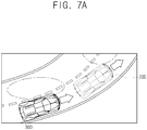
Figs. 7A and7B are diagrams exemplarily illustrating blind spot monitoring according to a driving environment of the monitoring vehicle in accordance with one example embodiment of the present invention. - Detailed explanation on the present invention to be made below refer to attached drawings and diagrams illustrated as specific embodiment examples under which the present invention may be implemented to make clear of purposes, technical solutions, and advantages of the present invention. These embodiments are described in sufficient detail to enable those skilled in the art to practice the invention.
- Besides, in the detailed description and claims of the present invention, a term "include" and its variations are not intended to exclude other technical features, additions, components or steps. Other objects, benefits and features of the present invention will be revealed to one skilled in the art, partially from the specification and partially from the implementation of the present invention. The following examples and drawings will be provided as examples but they are not intended to limit the present invention.
- Moreover, the present invention covers all possible combinations of example embodiments indicated in this specification. It is to be understood that the various embodiments of the present invention, although different, are not necessarily mutually exclusive. For example, a particular feature, structure, or characteristic described herein in connection with one embodiment may be implemented within other embodiments without departing from the spirit and scope of the present invention. In addition, it is to be understood that the position or arrangement of individual elements within each disclosed embodiment may be modified without departing from the spirit and scope of the present invention. The following detailed description is, therefore, not to be taken in a limiting sense, and the scope of the present invention is defined only by the appended claims, appropriately interpreted, along with the full range of equivalents to which the claims are entitled. In the drawings, like numerals refer to the same or similar functionality throughout the several views.
- To allow those skilled in the art to the present invention to be carried out easily, the example embodiments of the present invention by referring to attached diagrams will be explained in detail as shown below.
- First of all,
Fig. 1 is a block diagram schematically illustrating a blind spot monitoring system in accordance with one example embodiment of the present invention. By referring toFig. 1 , the blind spot monitoring system may include a blind spot monitor (BSM) 100 and amonitoring vehicle 200. For reference, theblind spot monitor 100 may be installed on themonitoring vehicle 200, but it is not limited to this. Further, by referring toFig. 1 , avision sensor 10, e.g., a camera, is illustrated as communicating with theblind spot monitor 100, however, it may be included in theblind spot monitor 100 or themonitoring vehicle 200. - The
blind spot monitor 100 may detect another vehicle, i.e., a monitored vehicle, located in a blind spot of the monitoringvehicle 200 or approaching the blind spot. As an example, theblind spot monitor 100 may determine whether a haphazard vehicle is located in the blind spot by analyzing at least one rear video image acquired from the monitoringvehicle 200 using the camera. - Then, the
monitoring vehicle 200 may be prevented from changing lanes in a direction to the blind spot where the haphazard vehicle is determined as located, or may allow an alarm system to warn a driver of a fact that the haphazard vehicle is in the blind spot, by referring to information on a steering system and information transmitted from theblind spot monitor 100. Especially, in case themonitoring vehicle 200 is an autonomous vehicle, it may determine whether to change lanes while driving by referring to information on driving environment and information on the haphazard vehicle in the blind spot received from the blind spot
blind spot monitor 100 may include acommunication part 110 that acquires the rear video image from themonitoring vehicle 200 in a driving state by using thevision sensor 10, and aprocessor 120 that determines whether the haphazard vehicle is in the blind spot of themonitoring vehicle 200 in the driving state by analyzing the acquired rear video image. Herein, thevision sensor 10, installed on an arbitrary place of themonitoring vehicle 200 as can be seen inFig. 2 , may capture video of a rear view thereof, and may include an optical sensor, e.g., a charge-coupled device (CCD), a complementary metal-oxide-semiconductor (CMOS), or an image capturing device. - In accordance with one example embodiment of the present invention, the
processor 120 may perform processes of (i) acquiring at least one feature map from the acquired rear video image, (ii) acquiring m proposal boxes corresponding to at least one object in the rear video image, (iii) applying pooling operation to each area, corresponding to the m proposal boxes, on the feature map, and (iv) acquiring each of feature vectors corresponding to each of the m proposal boxes. Further, theprocessor 120 input each of the feature vectors corresponding to each of the m proposal boxes into a first FC layer to acquire (i) each of first classification scores for each of first kinds of class, which correspond to each of the m proposal boxes, to confirm whether the object is a monitored vehicle, and (ii) each of second classification scores for each of second kinds of class, which correspond to each of the m proposal boxes, to confirm a pose of the object. Thereafter, theprocessor 120 may perform processes of (i) selecting n proposal boxes, which have probabilities over a certain threshold to be regarded as including the monitored vehicle, among the m proposal boxes by referring to the first classification scores, (ii) acquiring n bounding boxes, each of which corresponds to each of the n proposal boxes, by referring to regression information for vehicles which corresponds to each of the n proposal boxes, (iii) determining the pose of the monitored vehicle corresponding to each of at least some of the n bounding boxes by referring to the second classification scores, and (iv) determining whether a haphazard vehicle is located in the blind spot of themonitoring vehicle 200 by referring to at least some of the n bounding boxes and the pose of the monitored vehicle. That is, the monitored vehicle in the blind spot may be classified into the haphazard vehicle or not by referring to at least some of the n bounding boxes and the pose of the monitored vehicle. Herein, the first kinds of the class may be used for determining what the detected object is. For example, the first kinds may a vehicle class, a pedestrian class, a motorcycle class, and a dog class, etc. Also, the regression information for vehicles may be information corresponding to the vehicle class in the first kinds of the class, acquired by regression. - A method for monitoring whether the haphazard vehicle is located in the blind spot of the monitoring vehicle is explained more specifically by referring to
Figs. 3 and4 as below. - First, by referring to
Fig. 3 , thecommunication part 110 of theblind spot monitor 100 may acquire the rear video image of themonitoring vehicle 200 from thevision sensor 10 installed on themonitoring vehicle 200 in the driving state through thecommunication part 110, at the step of S10, and theprocessor 120 of theblind spot monitor 100 may acquire at least one feature map from the acquired rear video image. - As one example, the
processor 120 may perform or support another device to perform processes of (i) inputting the rear video image into a convolutional layer capable of applying at least one convolution operation to the rear video image and then (ii) acquiring the feature map through the convolutional layer, at the step of S21. - Herein, the
processor 120 may, on condition that a pad is set at zero, apply or support another device to apply convolution operation to the rear video image or its corresponding feature map, with a filter being slid at a predetermined stride. The pad is used for adjusting a size of output of the convolutional layer and the stride is an amount by which the filter shifts. In other words, theprocessor 120 may apply convolution operation to the rear video image or its corresponding feature map acquired therefrom to reduce their sizes. As opposed to this, theprocessor 120, on condition that the convolution is being performed with the pad set at a certain non-zero value, may perform processes of (i) acquiring at least one feature map with a size identical to that of the rear video image, (ii) downsizing the acquired feature map by applying pooling operation, and (iii) creating at least one additional feature map with at least one predetermined size by repeating the convolution and the pooling. - For reference, the
processor 120 may perform convolution using the convolutional layer over the whole area of each of the rear video image acquired from thevision sensor 10 or over parts of images corresponding to areas set as the blind spot on the rear video image. - The
processor 120 may acquire the m proposal boxes corresponding to the object in the rear video image. As one example, theprocessor 120 may input or support another device to input the feature map into a region proposal network (RPN) to acquire the m proposal boxes corresponding to the objects in the rear video image at the step of S22. - Thereafter, the
processor 120 may perform processes of (i) applying pooling operation to each area, corresponding to the m proposal boxes, on the feature map, and (ii) acquiring each of the feature vectors corresponding to each of the m proposal boxes, at the step of S23. - As one example, the
processor 120 may perform processes of (i) inputting each part of the feature map, which corresponds to each of the m proposal boxes, into a region of interest (ROI) pooling layer, (ii) applying max pooling or average pooling operation to said each part, thereby acquiring each of the feature vectors corresponding to each of the m proposal boxes. - Further, the
processor 120 may input or support another device to input each of the feature vectors into the first FC layer at the step of S24 to acquire each of the first classification scores for each of the first kinds of the class, at the step of S25. - Further, the
processor 120 may acquire each of the second classification scores for each of the second kinds of the class, at the step of S27. Herein, the second kinds of the class may be used for determining the pose of the monitored vehicle, which may correspond to a view of the monitored vehicle seen from themonitoring vehicle 200. - As one example, by referring to
Fig. 5 , the details of the second kinds of the class may be shown as follows. The view of the monitored vehicle seen from themonitoring vehicle 200 may be a rear face in case of (a), a rear face to the right in case of (b), a right face in case of (c), a front face to the right in case of (d), a front face in case of (e), a front face to the left in case of (f), a left face in case of (g), and a rear face to the left in case of (h). - In addition to this, the
processor 120 may further acquire regression information for each of the first kinds of the class, which corresponds to each of the m proposal boxes, by applying regression operation to the feature vectors through a second FC layer, at the step of S26. - Next, by referring to
Fig. 4 , theprocessor 120, on condition that the first classification scores and the regression information for each of the first kinds of the class to detect the monitored vehicle, and the second classification scores to determine the pose of the monitored vehicle are acquired at the step of S200 inFig. 3 , may perform processes of (i) determining the monitored vehicle located in the blind spot of themonitoring vehicle 200 by referring to the first classification scores and the regression information for each of the first kinds of the class, at the step of S300, and (ii) determining whether the haphazard vehicle is located in the blind spot of themonitoring vehicle 200 by referring to the pose of the monitored vehicle located in the blind spot inferred from the second classification scores, at the step of S400. - Specifically, the
processor 120 may perform processes of (i) selecting the n proposal boxes among the m proposal boxes by referring to the first classification scores, (ii) acquiring the n bounding boxes, each of which corresponds to each of the n proposal boxes, by referring to the regression information for vehicles which corresponds to each of the n proposal boxes, and (iii) detecting the monitored vehicles located in the rear video image. - Further, specifically, at the step of S300, the
processor 120 may determine k bounding boxes in the blind spot among the n bounding boxes corresponding to the monitored vehicles located in the rear video image. Theprocessor 120 may determine that the haphazard vehicle is located in the blind spot if the pose of the monitored vehicle in at least one of the k bounding boxes corresponds to a direction in which the monitoring vehicle is traveling, at the step of S400. - In detail, by referring to
Fig. 6 , theprocessor 120 may perform processes of (i) detecting the monitoredvehicles monitoring vehicle 200 by referring to the first classification scores and the regression information for vehicles, (ii) determining the poses of the detected monitoredvehicles Fig. 5 , theprocessor 120 may determine that the monitoredvehicle 310 is traveling in a same direction with themonitoring vehicle 200, and thus determine the monitoredvehicle 310 as the haphazard vehicle located in the blind spot. As opposed to this, if the pose of the monitoredvehicle 320 corresponds to the rear face, the rear face to the right, the right face, the left face, or the rear face to the left like (a), (b), (c), (g), or (h) inFig. 5 , theprocessor 120 may determine that the monitoredvehicle 320 is traveling in a different direction from themonitoring vehicle 200 and thus determine the monitoredvehicle 310 as not the haphazard vehicle. In other words, although the monitored vehicle is located in the blind spot, theprocessor 120 may determine that the monitored vehicle is not the haphazard vehicle, because the monitored vehicle is traveling in an opposite direction to themonitoring vehicle 200. - Further, if (i) a first bounding box among the k bounding boxes is determined as located in the blind spot formed in a back left area apart from the
monitoring vehicle 200, and (ii) the view of the monitored vehicle corresponds to the front face or the front face to the left, theprocessor 120 may determine that the haphazard vehicle is not located in the blind spot. Similarly, if (i) a second bounding box among the k bounding boxes is determined as located in the blind spot formed in a back right area apart from themonitoring vehicle 200, and (ii) the view of the monitored vehicle corresponds to the front face or the front face to the right, theprocessor 120 may determine that the haphazard vehicle is not located in the blind spot. - In other words, as in
Fig. 7A , if themonitoring vehicle 200 in the driving state is on a left-curved road and the monitoredvehicle 300 is following themonitoring vehicle 200 in the same lane, the monitoredvehicle 300 may be determined as located in the blind spot in the back left area of themonitoring vehicle 200. However, because the pose of the monitoredvehicle 300, as can be seen inFig. 7B , corresponds to the front face or the front face to the left like (e) or (f) inFig. 5 , theprocessor 120 may perform processes of confirming that the monitoredvehicle 300 is not the haphazard vehicle. - Similarly, if the
monitoring vehicle 200 in the driving state is on a right-curved road and the monitored vehicle is following themonitoring vehicle 200 in the same lane, the monitored vehicle may be determined as located in the blind spot formed in the back right area of themonitoring vehicle 200. However, because the pose of the monitored vehicle corresponds to the front face to the right or the front face like (d) or (e) inFig. 5 , theprocessor 120 may perform processes of confirming that the monitoredvehicle 300 is not the haphazard vehicle. - The
processor 120 may also perform or support another device to perform processes of (i) calculating first overlap ratios which are pairwise-overlapping ratios among the n bounding boxes, and then determining specific bounding boxes confirmed to have the first overlap ratios equal to or greater than a first threshold among the n bounding boxes as corresponding to a single identical monitored vehicle, (ii) calculating second overlap ratios which are pairwise-overlapping ratios among the specific bounding boxes and their respective corresponding proposal boxes, and then determining a certain bounding box with a maximum ratio among the second overlap ratios as including the single identical monitored vehicle. - As one example, (i) a first overlap ratio of a first bounding box overlapping a second bounding box may be calculated, and (ii) if the calculated first overlap ratio is equal to or greater than the first threshold, a second overlap ratio of the first bounding box overlapping a first proposal box and a third overlap ratio of the second bounding box overlapping a second proposal box may be calculated. Then, if the second overlap ratio is determined to be greater than the third overlap ratio, the first bounding box may be determined as including the monitored vehicle.
- Herein, the first overlap ratio may be calculated by dividing an area corresponding to intersection of the first bounding box and the second bounding box by an area corresponding to union of the first bounding box and the second bounding box. Further, the second overlap ratio may be calculated by dividing an area corresponding to intersection of the first bounding box and the first proposal box by an area corresponding to union of the first bounding box and the first proposal box. Furthermore, the third overlap ratio may be calculated by dividing an area corresponding to intersection of the second bounding box and the second proposal box by an area corresponding to union of the second bounding box and the second proposal box.
- As another example, the
processor 120 may perform processes of (i) calculating the first overlap ratios and (ii) determining particular bounding boxes confirmed to have the first overlap ratios less than a second threshold among the n bounding boxes as including respective monitored vehicles. Herein, the first threshold and the second threshold may be same with or different from each other. - Meanwhile, as mentioned above, the monitored vehicle is determined as located in the blind spot of the
monitoring vehicle 200 by referring to the first classification scores and the regression information for vehicles, and then the monitored vehicle is determined as the haphazard vehicle located in the blind spot by referring to the pose of the monitored vehicle. However, as another example, the monitored vehicle may be determined as traveling in the same direction with themonitoring vehicle 200 by referring to the first and the second classification scores, and then the monitored vehicle is determined as the haphazard vehicle located in the blind spot by referring to the regression information for vehicles on the monitored vehicle traveling in the same direction. - In other words, the
processor 120 may perform processes of (i) determining specific proposal boxes as including the monitored vehicles, among the m proposal boxes by referring to the first classification scores, (ii) selecting i proposal boxes determined as including at least one of the monitored vehicles whose pose corresponds to the traveling direction of themonitoring vehicle 200 among the specific proposal boxes by referring to the second classification scores. Then, theprocessor 120 may perform processes of (i) acquiring each of i bounding boxes corresponding to each of the i proposal boxes by referring to the regression information for vehicles which corresponds to each of the i proposal boxes, and (ii) determining whether there is at least one bounding box located in the blind spot of the monitoring vehicle among the i bounding boxes to thereby determine whether at least one haphazard vehicle is located in the blind spot. - Next, by referring to
Fig. 4 , theprocessor 120 may support a control unit of themonitoring vehicle 200 to prevent themonitoring vehicle 200 from changing lanes in a direction to the blind spot where the haphazard vehicle is determined as located, by transmitting information on the haphazard vehicle located in the blind spot to the control unit. - Herein, in case the driver intends to change lanes and the haphazard vehicle is detected as being located in the blind spot on the lane into which the driver intends to move, the control unit of the
monitoring vehicle 200 may allow the alarm system to warn the driver of the fact that the haphazard vehicle is in the blind spot and may allow the driver to avoid a hazardous situation which may arise from changing lanes, by referring to information on the steering system of themonitoring vehicle 200. Further, if themonitoring vehicle 200 is an autonomous vehicle, the control unit may allow the autonomous vehicle to change lanes safely by referring to information on the driving environment and information on whether the haphazard vehicle is located in the blind spot. - In the above, a process of confirmation of the haphazard vehicle in the blind spot is explained with respect to a single side, however, the confirmation thereof in each blind spot on both sides may be performed by following the same steps for the blind spot in the lane on the other side of the
monitoring vehicle 200. - Meanwhile, the blind spot monitor may include a CNN capable of performing operations of the convolution, the first classification, the second classification, and the regression by using at least one convolution parameter, at least one first classification parameter, at least one second classification parameter, and at least one regression parameter adjusted in advance.
- Further, the blind spot monitor may be divided into several devices to perform its functions, however, the present specification describes the blind spot monitor implemented as a single device for convenience.
- The blind spot monitor in accordance with the present invention may include part of the convolutional layer, the RPN, and the FC layer, etc.
- The present invention has an effect of accurately detecting the haphazard vehicle located in the blind spots by using the CNN.
- The present invention has another effect of accurately detecting the haphazard vehicle located in the blind spots without regard to the driving environment of the monitoring vehicle.
- The present invention has still another effect of detecting the haphazard vehicle located in the blind spots in real-time by less computation without regard to a change of a state of a background and a visual noise.
- The present invention has still yet another effect of detecting the haphazard vehicle located in the blind spot, according to the driving environment of the monitoring vehicle and the monitored vehicle.
- The present invention has still yet another effect of filtering vehicles in lanes of opposite direction with least computation without a need for lane detection by using a single detection network capable of performing vehicle detection and pose classification simultaneously, as opposed to conventional method of filtering the vehicles in lanes of opposite direction with lane detection which results in more computation and inaccuracy due to many missing lanes.
- The embodiments of the present invention as explained above can be implemented in a form of executable program command through a variety of computer means recordable to computer readable media. The computer readable media may include solely or in combination, program commands, data files, and data structures. The program commands recorded to the media may be components specially designed for the present invention or may be usable to a skilled human in a field of computer software. Computer readable media include magnetic media such as hard disk, floppy disk, and magnetic tape, optical media such as CD-ROM and DVD, magneto-optical media such as floptical disk and hardware devices such as ROM, RAM, and flash memory specially designed to store and carry out program commands. Program commands include not only a machine language code made by a complier but also a high level code that can be used by an interpreter etc., which is executed by a computer. The aforementioned hardware device can work as more than a software module to perform the action of the present invention and they can do the same in the opposite case.
- As seen above, the present invention has been explained by specific matters such as detailed components, limited embodiments, and drawings. They have been provided only to help more general understanding of the present invention. It, however, will be understood by those skilled in the art that various changes and modification may be made from the description without departing from the spirit and scope of the invention as defined in the following claims.
- Accordingly, the thought of the present invention must not be confined to the explained embodiments, and the following patent claims as well as everything including variations equal or equivalent to the patent claims pertain to the category of the thought of the present invention.
- Preferred embodiments of the invention are described in the followings paras:
- 1. A method for monitoring a blind spot of a vehicle, comprising steps of:
- (a) a blind spot monitor acquiring or supporting another device to acquire at least one feature map from a rear video image if the rear video image is acquired from a monitoring vehicle in a driving state;
- (b) the blind spot monitor performing or supporting another device to perform (i) a process of acquiring m proposal boxes corresponding to one or more objects located in the rear video image, (ii) a process of acquiring feature vectors each of which corresponds to each of the m proposal boxes by applying pooling operation to each area, on the feature map, corresponding to the m proposal boxes, and (iii) a process of inputting each of the feature vectors corresponding to each of the m proposal boxes into a first FC layer to acquire (iii-1) each of first classification scores for each of first kinds of class, which correspond to each of the m proposal boxes, to confirm whether the objects are monitored vehicles, and (iii-2) each of second classification scores for each of second kinds of class, which correspond to each of the m proposal boxes, to confirm poses of the objects; and
- (c) the blind spot monitor performing or supporting another device to perform (i) a process of selecting n proposal boxes, which have probabilities over a certain threshold to be regarded as including the monitored vehicle, among the m proposal boxes by referring to the first classification scores, (ii) a process of acquiring n bounding boxes, each of which corresponds to each of the n proposal boxes, by referring to regression information corresponding to each of the n proposal boxes, (iii) a process of determining the pose of the monitored vehicle corresponding to each of at least some of the n bounding boxes by referring to the second classification scores, and (iv) a process of determining whether a haphazard vehicle is located in a blind spot of the monitoring vehicle by referring to at least some of the n bounding boxes and the pose of the monitored vehicle.
- 2. The method of para 1, wherein, at the step of (b), the blind spot monitor performs or supports another device to perform a process of inputting each of the feature vectors corresponding to each of the m proposal boxes into a second FC layer to further acquire (iii-3) regression information for each of the first kinds of class, which corresponds to each of the m proposal boxes, by applying regression operation to the feature vectors through the second FC layer.
- 3. The method of para 1, further comprising a step of:
- (d) the blind spot monitor supporting a control unit to prevent the monitoring vehicle from changing lanes in a direction to the blind spot where the haphazard vehicle is located by transmitting information on the haphazard vehicle to the control unit if the haphazard vehicle is determined as located in the blind spot.
- 4. The method of para 1, wherein, at the step of (c), the blind spot monitor performs or supports another device to perform (i) a process of selecting k bounding boxes determined as located in the blind spot of the monitoring vehicle among the n bounding boxes, and then (ii) a process of determining that the haphazard vehicle is located in the blind spot if the pose of the monitored vehicle in at least one of the k bounding boxes corresponds to a direction in which the monitoring vehicle is traveling.
- 5. The method of para 4, wherein the blind spot monitor determines or supports another device to determine that the monitored vehicle is traveling in a same direction with the monitoring vehicle if a view of the monitored vehicle seen from the monitoring vehicle is a front face, a left front face, or a right front face.
- 6. The method of para 5, wherein the blind spot monitor determines or supports another device to determine the haphazard vehicle as not located in the blind spot of the monitoring vehicle if (i) first conditions that a first bounding box, among the k bounding boxes, is determined as located in the blind spot formed in a back left area apart from the monitoring vehicle and that the view of the monitored vehicle seen from the monitoring vehicle include the front face or the left front face or (ii) second conditions that a second bounding box, among the k bounding boxes, is determined as located in the blind spot formed in a back right area apart from the monitoring vehicle and that the view of the monitored vehicle seen from the monitoring vehicle include the front face or the right front face are satisfied.
- 7. The method of para 1, wherein, at the step of (c), the blind spot monitor performs or supports another device to perform (i) a process of calculating first overlap ratios which are pairwise-overlapping ratios among the n bounding boxes, (ii) a process of determining specific bounding boxes confirmed to have the first overlap ratios equal to or greater than a first threshold among the n bounding boxes as corresponding to a single identical monitored vehicle, (iii) a process of calculating second overlap ratios which are pairwise-overlapping ratios among the specific bounding boxes and their respective corresponding proposal boxes, and (iv) a process of determining a certain bounding box with a maximum ratio among the second overlap ratios as including the single identical monitored vehicle.
- 8. The method of para 1, wherein, at the step of (c), the blind spot monitor performs or supports another device to perform (i) a process of calculating first overlap ratios which represent pairwise-overlapping ratios among the n bounding boxes and (ii) a process of determining particular bounding boxes confirmed to have the first overlap ratios less than a second threshold among the n bounding boxes as including respective monitored vehicles.
- 9. The method of para 1, wherein, at the step of (a), the blind spot monitor applies or supports another device to apply convolution operation to the rear video image to thereby acquire the feature map.
- 10. The method of para 9, wherein, the blind spot monitor, on condition that a pad is set at zero, applies or supports another device to apply convolution operation to the rear video image or its corresponding feature map, with a filter being slid at a predetermined stride.
- 11. The method of para 1, wherein, at the step of (a), the blind spot monitor applies or supports another device to apply convolution operation to a part of the rear video image corresponding to the blind spot to thereby acquire the feature map.
- 12. A blind spot monitor for monitoring a blind spot of a vehicle, comprising:
- a communication part for acquiring or supporting another device to acquire a rear video image or its corresponding at least one feature map, wherein the rear video image is acquired from a monitoring vehicle in a driving state;
- a processor for performing or supporting another device to perform (i) a process of acquiring m proposal boxes corresponding to one or more objects located in the rear video image by using the feature map acquired from the communication part or the feature map calculated by applying one or more convolution operations to the rear video image map acquired from the communication part, (ii) a process of acquiring feature vectors each of which corresponds to each of the m proposal boxes by applying pooling operation to each area, on the feature map, corresponding to the m proposal boxes, (iii) a process of inputting each of the feature vectors corresponding to each of the m proposal boxes into a first FC layer to acquire (iii-1) each of first classification scores for each of first kinds of class, which correspond to each of the m proposal boxes, to confirm whether the objects are monitored vehicles, and (iii-2) each of second classification scores for each of second kinds of class, which correspond to each of the m proposal boxes, to confirm poses of the objects, (iv) a process of selecting n proposal boxes, which have probabilities over a certain threshold to be regarded as including the monitored vehicle, among the m proposal boxes by referring to the first classification scores, (v) a process of acquiring n bounding boxes, each of which corresponds to each of the n proposal boxes, by referring to regression information corresponding to each of the n proposal boxes, (vi) a process of determining the pose of the monitored vehicle corresponding to each of at least some of the n bounding boxes by referring to the second classification scores, and (vii) a process of determining whether a haphazard vehicle is located in a blind spot of the monitoring vehicle by referring to at least some of the n bounding boxes and the pose of the monitored vehicle.
- 13. The blind spot monitor of para 12, wherein, at the process of (iii), the processor performs or supports another device to perform a process of inputting each of the feature vectors corresponding to each of the m proposal boxes into a second FC layer to further acquire (iii-3) regression information for each of the first kinds of class, which corresponds to each of the m proposal boxes, by applying regression operation to the feature vectors through the second FC layer.
- 14. The blind spot monitor of para 12, wherein the processor further performs a process of supporting a control unit to prevent the monitoring vehicle from changing lanes in a direction to the blind spot where the haphazard vehicle is located by transmitting information on the haphazard vehicle to the control unit if the haphazard vehicle is determined as located in the blind spot.
- 15. The blind spot monitor of para 12, wherein, at the processes of (vi) and (vii), the processor performs or supports another device to perform a process of selecting k bounding boxes determined as located in the blind spot of the monitoring vehicle among the n bounding boxes, and then a process of determining that the haphazard vehicle is located in the blind spot if the pose of the monitored vehicle in at least one of the k bounding boxes corresponds to a direction in which the monitoring vehicle is traveling.
- 16. The blind spot monitor of para 15, wherein the processor determines or supports another device to determine that the monitored vehicle is traveling in a same direction with the monitoring vehicle if a view of the monitored vehicle seen from the monitoring vehicle is a front face, a left front face, or a right front face.
- 17. The blind spot monitor of para 16, wherein the processor determines or supports another device to determine the haphazard vehicle as not located in the blind spot of the monitoring vehicle if (i) first conditions that a first bounding box, among the k bounding boxes, is determined as located in the blind spot formed in a back left area apart from the monitoring vehicle and that the view of the monitored vehicle seen from the monitoring vehicle include the front face or the left front face or (ii) second conditions that a second bounding box, among the k bounding boxes, is determined as located in the blind spot formed in a back right area apart from the monitoring vehicle and that the view of the monitored vehicle seen from the monitoring vehicle include the front face or the right front face are satisfied.
- 18. The blind spot monitor of para 12, wherein, between the processes of (v) and (vi), the processor performs or supports another device to perform a process of calculating first overlap ratios which are pairwise-overlapping ratios among the n bounding boxes; a process of determining specific bounding boxes confirmed to have the first overlap ratios equal to or greater than a first threshold among the n bounding boxes as corresponding to a single identical monitored vehicle; a process of calculating second overlap ratios which are pairwise-overlapping ratios among the specific bounding boxes and their respective corresponding proposal boxes; and a process of determining a certain bounding box with a maximum ratio among the second overlap ratios as including the single identical monitored vehicle.
- 19. The blind spot monitor of para 12, wherein, at the process of (v), the processor performs or supports another device to perform a process of calculating first overlap ratios which represent pairwise-overlapping ratios among the n bounding boxes and a process of determining particular bounding boxes confirmed to have the first overlap ratios less than a second threshold among the n bounding boxes as including respective monitored vehicles.
- 20. The blind spot monitor of para 12, wherein the processor applies or supports another device to apply convolution operation to the rear video image to thereby acquire the feature map.
- 21. The blind spot monitor of para 20, wherein, the processor, on condition that a pad is set at zero, applies or supports another device to apply convolution operation to the rear video image or its corresponding feature map, with a filter being slid at a predetermined stride.
- 22. The blind spot monitor of para 12, wherein the processor applies or supports another device to apply convolution operation to a part of the rear video image corresponding to the blind spot to thereby acquire the feature map.
- 23. A method for monitoring a blind spot of a vehicle, comprising steps of:
- (a) a blind spot monitor acquiring or supporting another device to acquire at least one feature map from a rear video image if the rear video image is acquired from a monitoring vehicle in a driving state;
- (b) the blind spot monitor performing or supporting another device to perform (i) a process of acquiring m proposal boxes corresponding to one or more objects located in the rear video image, (ii) a process of acquiring feature vectors each of which corresponds to each of the m proposal boxes by applying pooling operation to each area, on the feature map, corresponding to the m proposal boxes, and (iii) a process of inputting each of the feature vectors corresponding to each of the m proposal boxes into an FC layer to acquire (iii-1) each of first classification scores for each of first kinds of class, which correspond to each of the m proposal boxes, to confirm whether the objects are monitored vehicles, and (iii-2) each of second classification scores for each of second kinds of class, which correspond to each of the m proposal boxes, to confirm poses of the objects; and
- (c) the blind spot monitor performing or supporting another device to perform (i) a process of determining specific proposal boxes as including the monitored vehicles among the m proposal boxes by referring to the first classification scores for each of first kinds of class, a process of selecting i proposal boxes determined as including at least one specific monitored vehicle whose pose corresponds to a traveling direction of the monitoring vehicle among the specific proposal boxes by referring to the second classification scores for each of the second kinds of class, (iii) a process of acquiring each of i bounding boxes corresponding to each of the i proposal boxes by referring to regression information corresponding to each of the i proposal boxes, and (iv) a process of determining whether there is at least one bounding box located in the blind spot of the monitoring vehicle among the i bounding boxes to thereby determine whether at least one haphazard vehicle is located in the blind spot.
- 24. The method of para 23, wherein, at the step of (b), the blind spot monitor performs or supports another device to perform a process of inputting each of the feature vectors corresponding to each of the m proposal boxes into the FC layer to further acquire (iii-3) regression information for each of the first kinds of class corresponding to each of the m proposal boxes, by applying regression operation to the feature vectors through the FC layer.
- 25. The method of para 23, wherein, at the step of (c), the blind spot monitor determines or supports another device to determine that the monitored vehicles are traveling in a same direction with the monitoring vehicle if views of the monitored vehicles seen from the monitoring vehicle include a front face, a left front face, or a right front face.
- 26. The method of
para 25, wherein the blind spot monitor determines or supports another device to determine the haphazard vehicle as not located in the blind spot of the monitoring vehicle if (i) first conditions that a first bounding box, among the i bounding boxes, is determined as located in the blind spot formed in a back left area apart from the monitoring vehicle, and that the views of the monitored vehicles seen from the monitoring vehicle include the front face or the left front face or (ii) second conditions that a second bounding box, among the i bounding boxes, is determined as located in the blind spot formed in a back right area apart from the monitoring vehicle, and that the views of the monitored vehicles seen from the monitoring vehicle include the front face or the right front face are satisfied. - 27. A blind spot monitor for monitoring a blind spot of a vehicle, comprising:
- a communication part for acquiring or supporting another device to acquire a rear video image or its corresponding at least one feature map, wherein the rear video image is acquired from a monitoring vehicle in a driving state;
- a processor for performing or supporting another device to perform (i) a process of acquiring m proposal boxes corresponding to one or more objects located in the rear video image by using the feature map acquired from the communication part or the feature map calculated by applying one or more convolution operations to the rear video image map acquired from the communication part, (ii) a process of acquiring feature vectors each of which corresponds to each of the m proposal boxes by applying pooling operation to each area, on the feature map, corresponding to the m proposal boxes, (iii) a process of inputting each of the feature vectors corresponding to each of the m proposal boxes into an FC layer to acquire (iii-1) each of first classification scores for each of first kinds of class, which correspond to each of the m proposal boxes, to confirm whether the objects are monitored vehicles, and (iii-2) each of second classification scores for each of second kinds of class, which correspond to each of the m proposal boxes, to confirm poses of the objects, (iv) a process of determining specific proposal boxes as including the monitored vehicles among the m proposal boxes by referring to the first classification scores for each of first kinds of class, (v) a process of selecting i proposal boxes determined as including at least one specific monitored vehicle whose pose corresponds to a traveling direction of the monitoring vehicle among the specific proposal boxes by referring to the second classification scores for each of the second kinds of class, (vi) a process of acquiring each of i bounding boxes corresponding to each of the i proposal boxes by referring to regression information corresponding to each of the i proposal boxes, and (vii) a process of determining whether there is at least one bounding box located in the blind spot of the monitoring vehicle among the i bounding boxes to thereby determine whether at least one haphazard vehicle is located in the blind spot.
- 28. The blind spot monitor of para 27, wherein, at the process of (iii), the process performs or supports another device to perform a process of inputting each of the feature vectors corresponding to each of the m proposal boxes into the FC layer to further acquire (iii-3) regression information for each of the first kinds of class corresponding to each of the m proposal boxes, by applying regression operation to the feature vectors through the FC layer.
- 29. The blind spot monitor of para 27, wherein, at the process of (v), the processor determines or supports another device to determine that the monitored vehicles are traveling in a same direction with the monitoring vehicle if views of the monitored vehicles seen from the monitoring vehicle include a front face, a left front face, or a right front face.
- 30. The blind spot monitor of para 29, wherein the processor determines or supports another device to determine the haphazard vehicle as not located in the blind spot of the monitoring vehicle if first conditions that a first bounding box, among the i bounding boxes, is determined as located in the blind spot formed in a back left area apart from the monitoring vehicle, and that the views of the monitored vehicles seen from the monitoring vehicle include the front face or the left front face or if second conditions that a second bounding box, among the i bounding boxes, is determined as located in the blind spot formed in a back right area apart from the monitoring vehicle, and that the views of the monitored vehicles seen from the monitoring vehicle include the front face or the right front face are satisfied.
Claims (18)
- A method for monitoring a blind spot of a vehicle, comprising steps of:(a) a blind spot monitor acquiring or supporting another device to acquire at least one feature map from a rear video image if the rear video image is acquired from a monitoring vehicle in a driving state;(b) the blind spot monitor performing or supporting another device to perform (i) a process of acquiring m proposal boxes corresponding to one or more objects located in the rear video image, (ii) a process of acquiring feature vectors each of which corresponds to each of the m proposal boxes by applying pooling operation to each area, on the feature map, corresponding to the m proposal boxes, and (iii) a process of inputting each of the feature vectors corresponding to each of the m proposal boxes into a first FC layer to acquire (iii-1) each of first classification scores for each of first kinds of class, which correspond to each of the m proposal boxes, to confirm whether the objects are monitored vehicles, and (iii-2) each of second classification scores for each of second kinds of class, which correspond to each of the m proposal boxes, to confirm poses of the objects; and(c) the blind spot monitor performing or supporting another device to perform (i) a process of selecting n proposal boxes, which have probabilities over a certain threshold to be regarded as including the monitored vehicle, among the m proposal boxes by referring to the first classification scores, (ii) a process of acquiring n bounding boxes, each of which corresponds to each of the n proposal boxes, by referring to regression information corresponding to each of the n proposal boxes, (iii) a process of determining the pose of the monitored vehicle corresponding to each of at least some of the n bounding boxes by referring to the second classification scores, and (iv) a process of determining whether a haphazard vehicle is located in a blind spot of the monitoring vehicle by referring to at least some of the n bounding boxes and the pose of the monitored vehicle.
- The method of Claim 1, wherein, at the step of (b), the blind spot monitor performs or supports another device to perform a process of inputting each of the feature vectors corresponding to each of the m proposal boxes into a second FC layer to further acquire (iii-3) regression information for each of the first kinds of class, which corresponds to each of the m proposal boxes, by applying regression operation to the feature vectors through the second FC layer.
- The method of Claim 1, further comprising a step of:(d) the blind spot monitor supporting a control unit to prevent the monitoring vehicle from changing lanes in a direction to the blind spot where the haphazard vehicle is located by transmitting information on the haphazard vehicle to the control unit if the haphazard vehicle is determined as located in the blind spot.
- The method of Claim 1, wherein, at the step of (c), the blind spot monitor performs or supports another device to perform (i) a process of selecting k bounding boxes determined as located in the blind spot of the monitoring vehicle among the n bounding boxes, and then (ii) a process of determining that the haphazard vehicle is located in the blind spot if the pose of the monitored vehicle in at least one of the k bounding boxes corresponds to a direction in which the monitoring vehicle is traveling.
- The method of Claim 4, wherein the blind spot monitor determines or supports another device to determine that the monitored vehicle is traveling in a same direction with the monitoring vehicle if a view of the monitored vehicle seen from the monitoring vehicle is a front face, a left front face, or a right front face.
- The method of Claim 5, wherein the blind spot monitor determines or supports another device to determine the haphazard vehicle as not located in the blind spot of the monitoring vehicle if (i) first conditions that a first bounding box, among the k bounding boxes, is determined as located in the blind spot formed in a back left area apart from the monitoring vehicle and that the view of the monitored vehicle seen from the monitoring vehicle include the front face or the left front face or (ii) second conditions that a second bounding box, among the k bounding boxes, is determined as located in the blind spot formed in a back right area apart from the monitoring vehicle and that the view of the monitored vehicle seen from the monitoring vehicle include the front face or the right front face are satisfied.
- The method of Claim 1, wherein, at the step of (c), the blind spot monitor performs or supports another device to perform (i) a process of calculating first overlap ratios which are pairwise-overlapping ratios among the n bounding boxes, (ii) a process of determining specific bounding boxes confirmed to have the first overlap ratios equal to or greater than a first threshold among the n bounding boxes as corresponding to a single identical monitored vehicle, (iii) a process of calculating second overlap ratios which are pairwise-overlapping ratios among the specific bounding boxes and their respective corresponding proposal boxes, and (iv) a process of determining a certain bounding box with a maximum ratio among the second overlap ratios as including the single identical monitored vehicle.
- The method of Claim 1, wherein, at the step of (c), the blind spot monitor performs or supports another device to perform (i) a process of calculating first overlap ratios which represent pairwise-overlapping ratios among the n bounding boxes and (ii) a process of determining particular bounding boxes confirmed to have the first overlap ratios less than a second threshold among the n bounding boxes as including respective monitored vehicles.
- A blind spot monitor for monitoring a blind spot of a vehicle, comprising:a communication part for acquiring or supporting another device to acquire a rear video image or its corresponding at least one feature map, wherein the rear video image is acquired from a monitoring vehicle in a driving state;a processor for performing or supporting another device to perform (i) a process of acquiring m proposal boxes corresponding to one or more objects located in the rear video image by using the feature map acquired from the communication part or the feature map calculated by applying one or more convolution operations to the rear video image map acquired from the communication part, (ii) a process of acquiring feature vectors each of which corresponds to each of the m proposal boxes by applying pooling operation to each area, on the feature map, corresponding to the m proposal boxes, (iii) a process of inputting each of the feature vectors corresponding to each of the m proposal boxes into a first FC layer to acquire (iii-1) each of first classification scores for each of first kinds of class, which correspond to each of the m proposal boxes, to confirm whether the objects are monitored vehicles, and (iii-2) each of second classification scores for each of second kinds of class, which correspond to each of the m proposal boxes, to confirm poses of the objects, (iv) a process of selecting n proposal boxes, which have probabilities over a certain threshold to be regarded as including the monitored vehicle, among the m proposal boxes by referring to the first classification scores, (v) a process of acquiring n bounding boxes, each of which corresponds to each of the n proposal boxes, by referring to regression information corresponding to each of the n proposal boxes, (vi) a process of determining the pose of the monitored vehicle corresponding to each of at least some of the n bounding boxes by referring to the second classification scores, and (vii) a process of determining whether a haphazard vehicle is located in a blind spot of the monitoring vehicle by referring to at least some of the n bounding boxes and the pose of the monitored vehicle.
- The blind spot monitor of Claim 9, wherein, at the process of (iii), the processor performs or supports another device to perform a process of inputting each of the feature vectors corresponding to each of the m proposal boxes into a second FC layer to further acquire (iii-3) regression information for each of the first kinds of class, which corresponds to each of the m proposal boxes, by applying regression operation to the feature vectors through the second FC layer.
- The blind spot monitor of Claim 9, wherein the processor further performs a process of supporting a control unit to prevent the monitoring vehicle from changing lanes in a direction to the blind spot where the haphazard vehicle is located by transmitting information on the haphazard vehicle to the control unit if the haphazard vehicle is determined as located in the blind spot.
- The blind spot monitor of Claim 9, wherein, at the processes of (vi) and (vii), the processor performs or supports another device to perform a process of selecting k bounding boxes determined as located in the blind spot of the monitoring vehicle among the n bounding boxes, and then a process of determining that the haphazard vehicle is located in the blind spot if the pose of the monitored vehicle in at least one of the k bounding boxes corresponds to a direction in which the monitoring vehicle is traveling.
- The blind spot monitor of Claim 12, wherein the processor determines or supports another device to determine that the monitored vehicle is traveling in a same direction with the monitoring vehicle if a view of the monitored vehicle seen from the monitoring vehicle is a front face, a left front face, or a right front face.
- The blind spot monitor of Claim 13, wherein the processor determines or supports another device to determine the haphazard vehicle as not located in the blind spot of the monitoring vehicle if (i) first conditions that a first bounding box, among the k bounding boxes, is determined as located in the blind spot formed in a back left area apart from the monitoring vehicle and that the view of the monitored vehicle seen from the monitoring vehicle include the front face or the left front face or (ii) second conditions that a second bounding box, among the k bounding boxes, is determined as located in the blind spot formed in a back right area apart from the monitoring vehicle and that the view of the monitored vehicle seen from the monitoring vehicle include the front face or the right front face are satisfied.
- The blind spot monitor of Claim 9, wherein, between the processes of (v) and (vi), the processor performs or supports another device to perform a process of calculating first overlap ratios which are pairwise-overlapping ratios among the n bounding boxes; a process of determining specific bounding boxes confirmed to have the first overlap ratios equal to or greater than a first threshold among the n bounding boxes as corresponding to a single identical monitored vehicle; a process of calculating second overlap ratios which are pairwise-overlapping ratios among the specific bounding boxes and their respective corresponding proposal boxes; and a process of determining a certain bounding box with a maximum ratio among the second overlap ratios as including the single identical monitored vehicle.
- The blind spot monitor of Claim 9, wherein, at the process of (v), the processor performs or supports another device to perform a process of calculating first overlap ratios which represent pairwise-overlapping ratios among the n bounding boxes and a process of determining particular bounding boxes confirmed to have the first overlap ratios less than a second threshold among the n bounding boxes as including respective monitored vehicles.
- A method for monitoring a blind spot of a vehicle, comprising steps of:(a) a blind spot monitor acquiring or supporting another device to acquire at least one feature map from a rear video image if the rear video image is acquired from a monitoring vehicle in a driving state;(b) the blind spot monitor performing or supporting another device to perform (i) a process of acquiring m proposal boxes corresponding to one or more objects located in the rear video image, (ii) a process of acquiring feature vectors each of which corresponds to each of the m proposal boxes by applying pooling operation to each area, on the feature map, corresponding to the m proposal boxes, and (iii) a process of inputting each of the feature vectors corresponding to each of the m proposal boxes into an FC layer to acquire (iii-1) each of first classification scores for each of first kinds of class, which correspond to each of the m proposal boxes, to confirm whether the objects are monitored vehicles, and (iii-2) each of second classification scores for each of second kinds of class, which correspond to each of the m proposal boxes, to confirm poses of the objects; and(c) the blind spot monitor performing or supporting another device to perform (i) a process of determining specific proposal boxes as including the monitored vehicles among the m proposal boxes by referring to the first classification scores for each of first kinds of class, a process of selecting i proposal boxes determined as including at least one specific monitored vehicle whose pose corresponds to a traveling direction of the monitoring vehicle among the specific proposal boxes by referring to the second classification scores for each of the second kinds of class, (iii) a process of acquiring each of i bounding boxes corresponding to each of the i proposal boxes by referring to regression information corresponding to each of the i proposal boxes, and (iv) a process of determining whether there is at least one bounding box located in the blind spot of the monitoring vehicle among the i bounding boxes to thereby determine whether at least one haphazard vehicle is located in the blind spot.
- A blind spot monitor for monitoring a blind spot of a vehicle, comprising:a communication part for acquiring or supporting another device to acquire a rear video image or its corresponding at least one feature map, wherein the rear video image is acquired from a monitoring vehicle in a driving state;a processor for performing or supporting another device to perform (i) a process of acquiring m proposal boxes corresponding to one or more objects located in the rear video image by using the feature map acquired from the communication part or the feature map calculated by applying one or more convolution operations to the rear video image map acquired from the communication part, (ii) a process of acquiring feature vectors each of which corresponds to each of the m proposal boxes by applying pooling operation to each area, on the feature map, corresponding to the m proposal boxes, (iii) a process of inputting each of the feature vectors corresponding to each of the m proposal boxes into an FC layer to acquire (iii-1) each of first classification scores for each of first kinds of class, which correspond to each of the m proposal boxes, to confirm whether the objects are monitored vehicles, and (iii-2) each of second classification scores for each of second kinds of class, which correspond to each of the m proposal boxes, to confirm poses of the objects, (iv) a process of determining specific proposal boxes as including the monitored vehicles among the m proposal boxes by referring to the first classification scores for each of first kinds of class, (v) a process of selecting i proposal boxes determined as including at least one specific monitored vehicle whose pose corresponds to a traveling direction of the monitoring vehicle among the specific proposal boxes by referring to the second classification scores for each of the second kinds of class, (vi) a process of acquiring each of i bounding boxes corresponding to each of the i proposal boxes by referring to regression information corresponding to each of the i proposal boxes, and (vii) a process of determining whether there is at least one bounding box located in the blind spot of the monitoring vehicle among the i bounding boxes to thereby determine whether at least one haphazard vehicle is located in the blind spot.
Applications Claiming Priority (1)
| Application Number | Priority Date | Filing Date | Title |
|---|---|---|---|
| US15/725,394 US9947228B1 (en) | 2017-10-05 | 2017-10-05 | Method for monitoring blind spot of vehicle and blind spot monitor using the same |
Publications (2)
| Publication Number | Publication Date |
|---|---|
| EP3467698A1 true EP3467698A1 (en) | 2019-04-10 |
| EP3467698B1 EP3467698B1 (en) | 2023-02-22 |
Family
ID=61872578
Family Applications (1)
| Application Number | Title | Priority Date | Filing Date |
|---|---|---|---|
| EP18192482.0A Active EP3467698B1 (en) | 2017-10-05 | 2018-09-04 | Method for monitoring blind spot of vehicle and blind spot monitor using the same |
Country Status (5)
| Country | Link |
|---|---|
| US (1) | US9947228B1 (en) |
| EP (1) | EP3467698B1 (en) |
| JP (1) | JP6704971B2 (en) |
| KR (1) | KR102098140B1 (en) |
| CN (1) | CN109624850B (en) |
Cited By (1)
| Publication number | Priority date | Publication date | Assignee | Title |
|---|---|---|---|---|
| WO2024081540A1 (en) * | 2022-10-14 | 2024-04-18 | Aurora Operations, Inc. | Autonomous vehicle blind spot management |
Families Citing this family (24)
| Publication number | Priority date | Publication date | Assignee | Title |
|---|---|---|---|---|
| US10353388B2 (en) | 2016-10-17 | 2019-07-16 | X Development Llc | Drop-off location planning for delivery vehicle |
| CN112534473A (en) * | 2018-08-22 | 2021-03-19 | 日立汽车系统株式会社 | Image processing apparatus and image processing method |
| US10311338B1 (en) * | 2018-09-15 | 2019-06-04 | StradVision, Inc. | Learning method, learning device for detecting lanes on the basis of CNN and testing method, testing device using the same |
| CN109460820A (en) * | 2018-09-28 | 2019-03-12 | 深圳百诺国际生命科技有限公司 | A kind of neural network training method, device, computer equipment and storage medium |
| US10474930B1 (en) * | 2018-10-05 | 2019-11-12 | StradVision, Inc. | Learning method and testing method for monitoring blind spot of vehicle, and learning device and testing device using the same |
| US10984262B2 (en) | 2018-10-08 | 2021-04-20 | StradVision, Inc. | Learning method and testing method for monitoring blind spot of vehicle, and learning device and testing device using the same |
| US10311321B1 (en) * | 2018-10-26 | 2019-06-04 | StradVision, Inc. | Learning method, learning device using regression loss and testing method, testing device using the same |
| US10509987B1 (en) | 2019-01-22 | 2019-12-17 | StradVision, Inc. | Learning method and learning device for object detector based on reconfigurable network for optimizing customers' requirements such as key performance index using target object estimating network and target object merging network, and testing method and testing device using the same |
| US10635915B1 (en) * | 2019-01-30 | 2020-04-28 | StradVision, Inc. | Method and device for warning blind spot cooperatively based on V2V communication with fault tolerance and fluctuation robustness in extreme situation |
| US10698222B1 (en) * | 2019-01-31 | 2020-06-30 | StradVision, Inc. | Method for monitoring blind spot of cycle using smart helmet for cycle rider and blind spot monitoring device using them |
| US11518465B2 (en) | 2019-03-27 | 2022-12-06 | Gentex Corporation | Motorcycle providing visual light warning to detected vehicles to notify detected vehicles of presence of motorcycle |
| US11433883B2 (en) | 2019-03-31 | 2022-09-06 | Gm Cruise Holdings Llc | Autonomous vehicle maneuvering based upon risk associated with occluded regions |
| CN110245263B (en) * | 2019-05-15 | 2021-08-20 | 北京奇艺世纪科技有限公司 | Aggregation method, aggregation device, electronic equipment and storage medium |
| CN110458225A (en) * | 2019-08-08 | 2019-11-15 | 北京深醒科技有限公司 | A kind of vehicle detection and posture are classified joint recognition methods |
| KR102155054B1 (en) * | 2019-11-28 | 2020-09-11 | 국민대학교산학협력단 | Method for predicting the intentional cut-in of neighboring vehicles using artificial intelligence |
| WO2021149095A1 (en) * | 2020-01-20 | 2021-07-29 | 三菱電機株式会社 | Movement assistance device, movement assistance learning device, and movement assistance method |
| KR102368441B1 (en) | 2020-05-28 | 2022-02-28 | 쌍용자동차 주식회사 | Blind spot monitoring apparatus and method combined with blind spot detection |
| US11501538B2 (en) * | 2020-08-24 | 2022-11-15 | Verizon Connect Development Limited | Systems and methods for detecting vehicle tailgating |
| KR20220026938A (en) * | 2020-08-26 | 2022-03-07 | 현대모비스 주식회사 | Rear lateral warning system and method of vehicle |
| CN112633258B (en) * | 2021-03-05 | 2021-05-25 | 天津所托瑞安汽车科技有限公司 | Target determination method and device, electronic equipment and computer readable storage medium |
| KR102345798B1 (en) * | 2021-03-18 | 2022-01-04 | (주)에이아이매틱스 | Intersection signal violation recognition and image storage device |
| CN113386669A (en) * | 2021-07-13 | 2021-09-14 | 虹软科技股份有限公司 | Driving assistance system and vehicle |
| JP7537411B2 (en) | 2021-11-11 | 2024-08-21 | トヨタ自動車株式会社 | Information processing system, information processing method, and program |
| KR102858189B1 (en) * | 2022-09-05 | 2025-09-11 | (주)오토노머스에이투지 | Learning method and learning device for supporting autonomous driving by generating information on surrounding vehicles based on machine learning and testing method and testing device using the same |
Citations (1)
| Publication number | Priority date | Publication date | Assignee | Title |
|---|---|---|---|---|
| US20170270374A1 (en) * | 2016-03-21 | 2017-09-21 | Ford Global Technologies, Llc | Pedestrian detection and motion prediction with rear-facing camera |
Family Cites Families (16)
| Publication number | Priority date | Publication date | Assignee | Title |
|---|---|---|---|---|
| DE102014100364B4 (en) * | 2013-01-18 | 2020-08-13 | Carnegie Mellon University | Method of determining whether an off-road eye condition exists |
| US9177214B1 (en) * | 2014-04-10 | 2015-11-03 | Xerox Corporation | Method and apparatus for an adaptive threshold based object detection |
| KR20160096460A (en) * | 2015-02-05 | 2016-08-16 | 삼성전자주식회사 | Recognition system based on deep learning including a plurality of classfier and control method thereof |
| US9141883B1 (en) * | 2015-05-11 | 2015-09-22 | StradVision, Inc. | Method, hard negative proposer, and classifier for supporting to collect hard negative images using a similarity map |
| CN106548127B (en) * | 2015-09-18 | 2022-11-04 | 松下电器(美国)知识产权公司 | Image recognition method |
| US20170124409A1 (en) * | 2015-11-04 | 2017-05-04 | Nec Laboratories America, Inc. | Cascaded neural network with scale dependent pooling for object detection |
| KR102592076B1 (en) * | 2015-12-14 | 2023-10-19 | 삼성전자주식회사 | Appartus and method for Object detection based on Deep leaning, apparatus for Learning thereof |
| CN105667397B (en) * | 2015-12-30 | 2018-10-16 | 深圳佑驾创新科技有限公司 | Rear-view system for automobile and method |
| KR20170086899A (en) * | 2016-01-19 | 2017-07-27 | 연세대학교 산학협력단 | Method and Apparatus for Cyclist Detection using Multi Camera |
| US9802599B2 (en) * | 2016-03-08 | 2017-10-31 | Ford Global Technologies, Llc | Vehicle lane placement |
| JP6690312B2 (en) * | 2016-03-09 | 2020-04-28 | 株式会社Jvcケンウッド | Vehicle display control device, vehicle display system, vehicle display control method and program |
| CN107180220B (en) * | 2016-03-11 | 2023-10-31 | 松下电器(美国)知识产权公司 | Hazard Prediction Methods |
| CN105975941B (en) * | 2016-05-31 | 2019-04-12 | 电子科技大学 | A kind of multi-direction vehicle detection identifying system based on deep learning |
| CN106407931B (en) * | 2016-09-19 | 2019-11-22 | 杭州电子科技大学 | A deep convolutional neural network moving vehicle detection method |
| CN106599773B (en) * | 2016-10-31 | 2019-12-24 | 清华大学 | Deep learning image identification method and system for intelligent driving and terminal equipment |
| CN106599827A (en) * | 2016-12-09 | 2017-04-26 | 浙江工商大学 | Small target rapid detection method based on deep convolution neural network |
-
2017
- 2017-10-05 US US15/725,394 patent/US9947228B1/en active Active
-
2018
- 2018-09-04 EP EP18192482.0A patent/EP3467698B1/en active Active
- 2018-10-02 KR KR1020180117332A patent/KR102098140B1/en active Active
- 2018-10-04 JP JP2018189176A patent/JP6704971B2/en active Active
- 2018-10-08 CN CN201811168140.4A patent/CN109624850B/en active Active
Patent Citations (1)
| Publication number | Priority date | Publication date | Assignee | Title |
|---|---|---|---|---|
| US20170270374A1 (en) * | 2016-03-21 | 2017-09-21 | Ford Global Technologies, Llc | Pedestrian detection and motion prediction with rear-facing camera |
Non-Patent Citations (1)
| Title |
|---|
| SHAOQING REN ET AL: "Faster R-CNN: Towards Real-Time Object Detection with Region Proposal Networks", IEEE TRANSACTIONS ON PATTERN ANALYSIS AND MACHINE INTELLIGENCE, vol. 39, no. 6, 1 June 2017 (2017-06-01), USA, pages 1137 - 1149, XP055525919, ISSN: 0162-8828, DOI: 10.1109/TPAMI.2016.2577031 * |
Cited By (2)
| Publication number | Priority date | Publication date | Assignee | Title |
|---|---|---|---|---|
| WO2024081540A1 (en) * | 2022-10-14 | 2024-04-18 | Aurora Operations, Inc. | Autonomous vehicle blind spot management |
| US12296856B2 (en) | 2022-10-14 | 2025-05-13 | Aurora Operations, Inc. | Autonomous vehicle blind spot management |
Also Published As
| Publication number | Publication date |
|---|---|
| CN109624850A (en) | 2019-04-16 |
| KR102098140B1 (en) | 2020-04-08 |
| US9947228B1 (en) | 2018-04-17 |
| KR20190039648A (en) | 2019-04-15 |
| CN109624850B (en) | 2022-04-08 |
| EP3467698B1 (en) | 2023-02-22 |
| JP2019071057A (en) | 2019-05-09 |
| JP6704971B2 (en) | 2020-06-03 |
Similar Documents
| Publication | Publication Date | Title |
|---|---|---|
| US9947228B1 (en) | Method for monitoring blind spot of vehicle and blind spot monitor using the same | |
| US9934440B1 (en) | Method for monitoring blind spot of monitoring vehicle and blind spot monitor using the same | |
| JP6872260B2 (en) | A method of warning the danger of changing lanes of a car and an alarm device using this | |
| US11104327B2 (en) | Method for automated parking of a vehicle | |
| EP3343438B1 (en) | Automatic parking system and automatic parking method | |
| EP3961580B1 (en) | Apparatus, method, and computer program for object detection | |
| US20170297488A1 (en) | Surround view camera system for object detection and tracking | |
| US10000210B2 (en) | Lane recognition apparatus | |
| CN107179767B (en) | Driving control device, driving control method, and non-transitory recording medium | |
| US20240383479A1 (en) | Vehicular sensing system with lateral threat assessment | |
| JP3952305B2 (en) | Moving object periphery monitoring device, moving object periphery monitoring method, control program, and readable recording medium | |
| EP4113377A1 (en) | Use of dbscan for lane detection | |
| EP4125063A1 (en) | Methods and systems for occupancy class prediction and methods and systems for occlusion value determination | |
| KR102322815B1 (en) | Electronic Device and the Method for Detecting Occupancy Lane of Road Event Based on Camera | |
| JP7117922B2 (en) | Perimeter recognition device and in-vehicle camera system | |
| KR20180070125A (en) | Autonomous Emergency Braking System And Method of Driving thereof | |
| CN114511834A (en) | Method and device for determining prompt information, electronic equipment and storage medium | |
| US11417115B2 (en) | Obstacle recognition device | |
| CN114325756B (en) | Short-distance obstacle avoidance method and device based on laser radar, vehicle and storage medium | |
| CN114119576B (en) | Image processing methods, devices, electronic equipment and vehicles | |
| CN120246008A (en) | Vehicle system and method for pedestrian road crossing prediction |
Legal Events
| Date | Code | Title | Description |
|---|---|---|---|
| PUAI | Public reference made under article 153(3) epc to a published international application that has entered the european phase |
Free format text: ORIGINAL CODE: 0009012 |
|
| STAA | Information on the status of an ep patent application or granted ep patent |
Free format text: STATUS: REQUEST FOR EXAMINATION WAS MADE |
|
| 17P | Request for examination filed |
Effective date: 20180904 |
|
| AK | Designated contracting states |
Kind code of ref document: A1 Designated state(s): AL AT BE BG CH CY CZ DE DK EE ES FI FR GB GR HR HU IE IS IT LI LT LU LV MC MK MT NL NO PL PT RO RS SE SI SK SM TR |
|
| AX | Request for extension of the european patent |
Extension state: BA ME |
|
| RIN1 | Information on inventor provided before grant (corrected) |
Inventor name: JANG, TAEWOONG Inventor name: RYU, WOOJU Inventor name: BOO, SUKHOON Inventor name: YEO, DONGHUN Inventor name: CHO, HOJIN Inventor name: JE, HONGMO Inventor name: KIM, YONGJOONG Inventor name: NAM, WOONHYUN Inventor name: SUNG, MYUNGCHUL Inventor name: JEONG, KYUNGJOONG |
|
| STAA | Information on the status of an ep patent application or granted ep patent |
Free format text: STATUS: EXAMINATION IS IN PROGRESS |
|
| 17Q | First examination report despatched |
Effective date: 20210302 |
|
| REG | Reference to a national code |
Ref country code: DE Ref legal event code: R079 Ref document number: 602018046358 Country of ref document: DE Free format text: PREVIOUS MAIN CLASS: H99Z9999999999 Ipc: G06V0020580000 |
|
| GRAP | Despatch of communication of intention to grant a patent |
Free format text: ORIGINAL CODE: EPIDOSNIGR1 |
|
| STAA | Information on the status of an ep patent application or granted ep patent |
Free format text: STATUS: GRANT OF PATENT IS INTENDED |
|
| RIC1 | Information provided on ipc code assigned before grant |
Ipc: G06V 20/58 20220101AFI20220823BHEP |
|
| INTG | Intention to grant announced |
Effective date: 20220922 |
|
| GRAS | Grant fee paid |
Free format text: ORIGINAL CODE: EPIDOSNIGR3 |
|
| GRAA | (expected) grant |
Free format text: ORIGINAL CODE: 0009210 |
|
| STAA | Information on the status of an ep patent application or granted ep patent |
Free format text: STATUS: THE PATENT HAS BEEN GRANTED |
|
| AK | Designated contracting states |
Kind code of ref document: B1 Designated state(s): AL AT BE BG CH CY CZ DE DK EE ES FI FR GB GR HR HU IE IS IT LI LT LU LV MC MK MT NL NO PL PT RO RS SE SI SK SM TR |
|
| REG | Reference to a national code |
Ref country code: GB Ref legal event code: FG4D |
|
| REG | Reference to a national code |
Ref country code: CH Ref legal event code: EP |
|
| REG | Reference to a national code |
Ref country code: AT Ref legal event code: REF Ref document number: 1550011 Country of ref document: AT Kind code of ref document: T Effective date: 20230315 Ref country code: IE Ref legal event code: FG4D |
|
| REG | Reference to a national code |
Ref country code: DE Ref legal event code: R096 Ref document number: 602018046358 Country of ref document: DE |
|
| REG | Reference to a national code |
Ref country code: SE Ref legal event code: TRGR |
|
| REG | Reference to a national code |
Ref country code: LT Ref legal event code: MG9D |
|
| P01 | Opt-out of the competence of the unified patent court (upc) registered |
Effective date: 20230522 |
|
| REG | Reference to a national code |
Ref country code: NL Ref legal event code: MP Effective date: 20230222 |
|
| REG | Reference to a national code |
Ref country code: AT Ref legal event code: MK05 Ref document number: 1550011 Country of ref document: AT Kind code of ref document: T Effective date: 20230222 |
|
| PG25 | Lapsed in a contracting state [announced via postgrant information from national office to epo] |
Ref country code: RS Free format text: LAPSE BECAUSE OF FAILURE TO SUBMIT A TRANSLATION OF THE DESCRIPTION OR TO PAY THE FEE WITHIN THE PRESCRIBED TIME-LIMIT Effective date: 20230222 Ref country code: PT Free format text: LAPSE BECAUSE OF FAILURE TO SUBMIT A TRANSLATION OF THE DESCRIPTION OR TO PAY THE FEE WITHIN THE PRESCRIBED TIME-LIMIT Effective date: 20230622 Ref country code: NO Free format text: LAPSE BECAUSE OF FAILURE TO SUBMIT A TRANSLATION OF THE DESCRIPTION OR TO PAY THE FEE WITHIN THE PRESCRIBED TIME-LIMIT Effective date: 20230522 Ref country code: NL Free format text: LAPSE BECAUSE OF FAILURE TO SUBMIT A TRANSLATION OF THE DESCRIPTION OR TO PAY THE FEE WITHIN THE PRESCRIBED TIME-LIMIT Effective date: 20230222 Ref country code: LV Free format text: LAPSE BECAUSE OF FAILURE TO SUBMIT A TRANSLATION OF THE DESCRIPTION OR TO PAY THE FEE WITHIN THE PRESCRIBED TIME-LIMIT Effective date: 20230222 Ref country code: LT Free format text: LAPSE BECAUSE OF FAILURE TO SUBMIT A TRANSLATION OF THE DESCRIPTION OR TO PAY THE FEE WITHIN THE PRESCRIBED TIME-LIMIT Effective date: 20230222 Ref country code: HR Free format text: LAPSE BECAUSE OF FAILURE TO SUBMIT A TRANSLATION OF THE DESCRIPTION OR TO PAY THE FEE WITHIN THE PRESCRIBED TIME-LIMIT Effective date: 20230222 Ref country code: ES Free format text: LAPSE BECAUSE OF FAILURE TO SUBMIT A TRANSLATION OF THE DESCRIPTION OR TO PAY THE FEE WITHIN THE PRESCRIBED TIME-LIMIT Effective date: 20230222 Ref country code: AT Free format text: LAPSE BECAUSE OF FAILURE TO SUBMIT A TRANSLATION OF THE DESCRIPTION OR TO PAY THE FEE WITHIN THE PRESCRIBED TIME-LIMIT Effective date: 20230222 |
|
| PG25 | Lapsed in a contracting state [announced via postgrant information from national office to epo] |
Ref country code: PL Free format text: LAPSE BECAUSE OF FAILURE TO SUBMIT A TRANSLATION OF THE DESCRIPTION OR TO PAY THE FEE WITHIN THE PRESCRIBED TIME-LIMIT Effective date: 20230222 Ref country code: IS Free format text: LAPSE BECAUSE OF FAILURE TO SUBMIT A TRANSLATION OF THE DESCRIPTION OR TO PAY THE FEE WITHIN THE PRESCRIBED TIME-LIMIT Effective date: 20230622 Ref country code: GR Free format text: LAPSE BECAUSE OF FAILURE TO SUBMIT A TRANSLATION OF THE DESCRIPTION OR TO PAY THE FEE WITHIN THE PRESCRIBED TIME-LIMIT Effective date: 20230523 Ref country code: FI Free format text: LAPSE BECAUSE OF FAILURE TO SUBMIT A TRANSLATION OF THE DESCRIPTION OR TO PAY THE FEE WITHIN THE PRESCRIBED TIME-LIMIT Effective date: 20230222 |
|
| PG25 | Lapsed in a contracting state [announced via postgrant information from national office to epo] |
Ref country code: SM Free format text: LAPSE BECAUSE OF FAILURE TO SUBMIT A TRANSLATION OF THE DESCRIPTION OR TO PAY THE FEE WITHIN THE PRESCRIBED TIME-LIMIT Effective date: 20230222 Ref country code: RO Free format text: LAPSE BECAUSE OF FAILURE TO SUBMIT A TRANSLATION OF THE DESCRIPTION OR TO PAY THE FEE WITHIN THE PRESCRIBED TIME-LIMIT Effective date: 20230222 Ref country code: EE Free format text: LAPSE BECAUSE OF FAILURE TO SUBMIT A TRANSLATION OF THE DESCRIPTION OR TO PAY THE FEE WITHIN THE PRESCRIBED TIME-LIMIT Effective date: 20230222 Ref country code: DK Free format text: LAPSE BECAUSE OF FAILURE TO SUBMIT A TRANSLATION OF THE DESCRIPTION OR TO PAY THE FEE WITHIN THE PRESCRIBED TIME-LIMIT Effective date: 20230222 Ref country code: CZ Free format text: LAPSE BECAUSE OF FAILURE TO SUBMIT A TRANSLATION OF THE DESCRIPTION OR TO PAY THE FEE WITHIN THE PRESCRIBED TIME-LIMIT Effective date: 20230222 |
|
| REG | Reference to a national code |
Ref country code: DE Ref legal event code: R097 Ref document number: 602018046358 Country of ref document: DE |
|
| PG25 | Lapsed in a contracting state [announced via postgrant information from national office to epo] |
Ref country code: SK Free format text: LAPSE BECAUSE OF FAILURE TO SUBMIT A TRANSLATION OF THE DESCRIPTION OR TO PAY THE FEE WITHIN THE PRESCRIBED TIME-LIMIT Effective date: 20230222 |
|
| PLBE | No opposition filed within time limit |
Free format text: ORIGINAL CODE: 0009261 |
|
| STAA | Information on the status of an ep patent application or granted ep patent |
Free format text: STATUS: NO OPPOSITION FILED WITHIN TIME LIMIT |
|
| 26N | No opposition filed |
Effective date: 20231123 |
|
| PG25 | Lapsed in a contracting state [announced via postgrant information from national office to epo] |
Ref country code: SI Free format text: LAPSE BECAUSE OF FAILURE TO SUBMIT A TRANSLATION OF THE DESCRIPTION OR TO PAY THE FEE WITHIN THE PRESCRIBED TIME-LIMIT Effective date: 20230222 |
|
| REG | Reference to a national code |
Ref country code: CH Ref legal event code: PL |
|
| PG25 | Lapsed in a contracting state [announced via postgrant information from national office to epo] |
Ref country code: LU Free format text: LAPSE BECAUSE OF NON-PAYMENT OF DUE FEES Effective date: 20230904 |
|
| REG | Reference to a national code |
Ref country code: BE Ref legal event code: MM Effective date: 20230930 |
|
| GBPC | Gb: european patent ceased through non-payment of renewal fee |
Effective date: 20230904 |
|
| PG25 | Lapsed in a contracting state [announced via postgrant information from national office to epo] |
Ref country code: LU Free format text: LAPSE BECAUSE OF NON-PAYMENT OF DUE FEES Effective date: 20230904 Ref country code: MC Free format text: LAPSE BECAUSE OF FAILURE TO SUBMIT A TRANSLATION OF THE DESCRIPTION OR TO PAY THE FEE WITHIN THE PRESCRIBED TIME-LIMIT Effective date: 20230222 |
|
| REG | Reference to a national code |
Ref country code: IE Ref legal event code: MM4A |
|
| PG25 | Lapsed in a contracting state [announced via postgrant information from national office to epo] |
Ref country code: IE Free format text: LAPSE BECAUSE OF NON-PAYMENT OF DUE FEES Effective date: 20230904 |
|
| PG25 | Lapsed in a contracting state [announced via postgrant information from national office to epo] |
Ref country code: GB Free format text: LAPSE BECAUSE OF NON-PAYMENT OF DUE FEES Effective date: 20230904 |
|
| PG25 | Lapsed in a contracting state [announced via postgrant information from national office to epo] |
Ref country code: CH Free format text: LAPSE BECAUSE OF NON-PAYMENT OF DUE FEES Effective date: 20230930 |
|
| PG25 | Lapsed in a contracting state [announced via postgrant information from national office to epo] |
Ref country code: IE Free format text: LAPSE BECAUSE OF NON-PAYMENT OF DUE FEES Effective date: 20230904 Ref country code: GB Free format text: LAPSE BECAUSE OF NON-PAYMENT OF DUE FEES Effective date: 20230904 Ref country code: FR Free format text: LAPSE BECAUSE OF NON-PAYMENT OF DUE FEES Effective date: 20230930 Ref country code: CH Free format text: LAPSE BECAUSE OF NON-PAYMENT OF DUE FEES Effective date: 20230930 |
|
| PG25 | Lapsed in a contracting state [announced via postgrant information from national office to epo] |
Ref country code: BE Free format text: LAPSE BECAUSE OF NON-PAYMENT OF DUE FEES Effective date: 20230930 |
|
| PG25 | Lapsed in a contracting state [announced via postgrant information from national office to epo] |
Ref country code: BG Free format text: LAPSE BECAUSE OF FAILURE TO SUBMIT A TRANSLATION OF THE DESCRIPTION OR TO PAY THE FEE WITHIN THE PRESCRIBED TIME-LIMIT Effective date: 20230222 |
|
| PG25 | Lapsed in a contracting state [announced via postgrant information from national office to epo] |
Ref country code: BG Free format text: LAPSE BECAUSE OF FAILURE TO SUBMIT A TRANSLATION OF THE DESCRIPTION OR TO PAY THE FEE WITHIN THE PRESCRIBED TIME-LIMIT Effective date: 20230222 |
|
| PG25 | Lapsed in a contracting state [announced via postgrant information from national office to epo] |
Ref country code: CY Free format text: LAPSE BECAUSE OF FAILURE TO SUBMIT A TRANSLATION OF THE DESCRIPTION OR TO PAY THE FEE WITHIN THE PRESCRIBED TIME-LIMIT; INVALID AB INITIO Effective date: 20180904 |
|
| PG25 | Lapsed in a contracting state [announced via postgrant information from national office to epo] |
Ref country code: HU Free format text: LAPSE BECAUSE OF FAILURE TO SUBMIT A TRANSLATION OF THE DESCRIPTION OR TO PAY THE FEE WITHIN THE PRESCRIBED TIME-LIMIT; INVALID AB INITIO Effective date: 20180904 |
|
| PGFP | Annual fee paid to national office [announced via postgrant information from national office to epo] |
Ref country code: SE Payment date: 20250922 Year of fee payment: 8 |
|
| PG25 | Lapsed in a contracting state [announced via postgrant information from national office to epo] |
Ref country code: TR Free format text: LAPSE BECAUSE OF FAILURE TO SUBMIT A TRANSLATION OF THE DESCRIPTION OR TO PAY THE FEE WITHIN THE PRESCRIBED TIME-LIMIT Effective date: 20230222 |
|
| PGFP | Annual fee paid to national office [announced via postgrant information from national office to epo] |
Ref country code: DE Payment date: 20251121 Year of fee payment: 8 |
|
| PGFP | Annual fee paid to national office [announced via postgrant information from national office to epo] |
Ref country code: IT Payment date: 20250930 Year of fee payment: 8 |