EP3467632A1 - Method for operating electronic device, electronic device and computer-readable recording medium thereof - Google Patents
Method for operating electronic device, electronic device and computer-readable recording medium thereof Download PDFInfo
- Publication number
- EP3467632A1 EP3467632A1 EP17203762.4A EP17203762A EP3467632A1 EP 3467632 A1 EP3467632 A1 EP 3467632A1 EP 17203762 A EP17203762 A EP 17203762A EP 3467632 A1 EP3467632 A1 EP 3467632A1
- Authority
- EP
- European Patent Office
- Prior art keywords
- electronic device
- sensor
- triggering operation
- clamping
- pattern
- Prior art date
- Legal status (The legal status is an assumption and is not a legal conclusion. Google has not performed a legal analysis and makes no representation as to the accuracy of the status listed.)
- Granted
Links
Images



Classifications
-
- G—PHYSICS
- G06—COMPUTING OR CALCULATING; COUNTING
- G06F—ELECTRIC DIGITAL DATA PROCESSING
- G06F3/00—Input arrangements for transferring data to be processed into a form capable of being handled by the computer; Output arrangements for transferring data from processing unit to output unit, e.g. interface arrangements
- G06F3/01—Input arrangements or combined input and output arrangements for interaction between user and computer
- G06F3/048—Interaction techniques based on graphical user interfaces [GUI]
- G06F3/0487—Interaction techniques based on graphical user interfaces [GUI] using specific features provided by the input device, e.g. functions controlled by the rotation of a mouse with dual sensing arrangements, or of the nature of the input device, e.g. tap gestures based on pressure sensed by a digitiser
-
- G—PHYSICS
- G06—COMPUTING OR CALCULATING; COUNTING
- G06F—ELECTRIC DIGITAL DATA PROCESSING
- G06F3/00—Input arrangements for transferring data to be processed into a form capable of being handled by the computer; Output arrangements for transferring data from processing unit to output unit, e.g. interface arrangements
- G06F3/01—Input arrangements or combined input and output arrangements for interaction between user and computer
- G06F3/048—Interaction techniques based on graphical user interfaces [GUI]
- G06F3/0487—Interaction techniques based on graphical user interfaces [GUI] using specific features provided by the input device, e.g. functions controlled by the rotation of a mouse with dual sensing arrangements, or of the nature of the input device, e.g. tap gestures based on pressure sensed by a digitiser
- G06F3/0488—Interaction techniques based on graphical user interfaces [GUI] using specific features provided by the input device, e.g. functions controlled by the rotation of a mouse with dual sensing arrangements, or of the nature of the input device, e.g. tap gestures based on pressure sensed by a digitiser using a touch-screen or digitiser, e.g. input of commands through traced gestures
- G06F3/04883—Interaction techniques based on graphical user interfaces [GUI] using specific features provided by the input device, e.g. functions controlled by the rotation of a mouse with dual sensing arrangements, or of the nature of the input device, e.g. tap gestures based on pressure sensed by a digitiser using a touch-screen or digitiser, e.g. input of commands through traced gestures for inputting data by handwriting, e.g. gesture or text
-
- G—PHYSICS
- G06—COMPUTING OR CALCULATING; COUNTING
- G06F—ELECTRIC DIGITAL DATA PROCESSING
- G06F3/00—Input arrangements for transferring data to be processed into a form capable of being handled by the computer; Output arrangements for transferring data from processing unit to output unit, e.g. interface arrangements
- G06F3/01—Input arrangements or combined input and output arrangements for interaction between user and computer
- G06F3/02—Input arrangements using manually operated switches, e.g. using keyboards or dials
- G06F3/0227—Cooperation and interconnection of the input arrangement with other functional units of a computer
-
- G—PHYSICS
- G06—COMPUTING OR CALCULATING; COUNTING
- G06F—ELECTRIC DIGITAL DATA PROCESSING
- G06F1/00—Details not covered by groups G06F3/00 - G06F13/00 and G06F21/00
- G06F1/16—Constructional details or arrangements
- G06F1/1613—Constructional details or arrangements for portable computers
- G06F1/1633—Constructional details or arrangements of portable computers not specific to the type of enclosures covered by groups G06F1/1615 - G06F1/1626
- G06F1/1684—Constructional details or arrangements related to integrated I/O peripherals not covered by groups G06F1/1635 - G06F1/1675
-
- G—PHYSICS
- G06—COMPUTING OR CALCULATING; COUNTING
- G06F—ELECTRIC DIGITAL DATA PROCESSING
- G06F3/00—Input arrangements for transferring data to be processed into a form capable of being handled by the computer; Output arrangements for transferring data from processing unit to output unit, e.g. interface arrangements
- G06F3/01—Input arrangements or combined input and output arrangements for interaction between user and computer
- G06F3/03—Arrangements for converting the position or the displacement of a member into a coded form
- G06F3/033—Pointing devices displaced or positioned by the user, e.g. mice, trackballs, pens or joysticks; Accessories therefor
- G06F3/0354—Pointing devices displaced or positioned by the user, e.g. mice, trackballs, pens or joysticks; Accessories therefor with detection of two-dimensional [2D] relative movements between the device, or an operating part thereof, and a plane or surface, e.g. 2D mice, trackballs, pens or pucks
- G06F3/03547—Touch pads, in which fingers can move on a surface
-
- G—PHYSICS
- G06—COMPUTING OR CALCULATING; COUNTING
- G06F—ELECTRIC DIGITAL DATA PROCESSING
- G06F2203/00—Indexing scheme relating to G06F3/00 - G06F3/048
- G06F2203/033—Indexing scheme relating to G06F3/033
- G06F2203/0339—Touch strips, e.g. orthogonal touch strips to control cursor movement or scrolling; single touch strip to adjust parameter or to implement a row of soft keys
Definitions
- the invention relates a method for operating an electronic device, an electronic device, and a computer-readable recording medium thereof, and more particularly, relates to an electronic device being operated through sensors disposed on the sides of the electronic device.
- the disclosure is directed to an operating method, an electronic device and a computer-readable recording medium for automatically launching or starting an application program based on sensor data of sensors disposed on at least one side of the electronic device.
- an electronic device in one of the exemplary embodiments, includes a body, at least one sensor and a processor.
- the body may comprise a back and a front with a display.
- the at least one sensor is disposed on one side of the body.
- the processor is coupled to the at least one sensors to receive a sensor data.
- the processor is configured to identify a first triggering operation and a second triggering operation based on the received sensor data.
- the processor is configured to execute the first triggering operation and not execute the second triggering operation when determined, wherein the first triggering operation is a clamping action, and the second triggering operation is associated to a squeeze action.
- the processor performs a first function (or start an application program).
- the processor in response to the first triggering operation, is further configured to identify a clamping pattern based on the sensor data, compare the identified clamping pattern to a predetermined pattern predefined as a corresponding pattern for a first function, and perform the first function based on the comparison result.
- the at least one sensor includes a first sensor disposed on a first side of the body and a second sensor disposed on a second side of the body opposite to the first side.
- the processor is further configured to identify a clamping pattern based on the sensor data, compare the identified clamping pattern to a predetermined pattern predefined as a corresponding pattern for a first function, and perform the first function based on the comparison result.
- the processor further incorporates information regarding to the status of the display (on or off) for determining a function or application program to perform.
- the processor further incorporates information regarding to an accelerometer for determining a function or application program to perform.
- a method for operating an electronic device where the electronic device includes at least one sensor disposed on one side of the electronic device, and the method includes the following steps.
- Sensor data is obtained from the at least one sensor.
- a first triggering operation and a second triggering operation is identified based on the obtained sensor data.
- the first triggering operation and not executing the second triggering operation is executed when, determined, based on the sensor data, that a pressure applied on the side of the body remains within a constant range for a predetermined period of time.
- the computer-readable recording medium records computer program to be loaded into a processor in an electronic device to execute the steps of the aforementioned method.
- a novel method for operating an electronic device is provided.
- outputs from at least one sensor disposed on a side of the electronic device which are also referred to edge sensor, is utilized for triggering functional operations of the electronic device.
- the electronic device predicts user's next desired operation and automatically perform a function by launching or starting an application program installed on the electronic device.
- Exemplary embodiments are described below to illustrate an electronic device having the edge sensors and operation of the electronic device through the edge sensors.
- FIGs. 1A and 1B are a diagram illustrating an electronic device 100 according to one of the exemplary embodiments of the disclosure.
- the electronic device 100 includes a body 110, a first sensor 120, and a second sensor 130.
- the body 110 includes, in addition to the back and the front with a display 140, a first side S1 and a second side S2, where the first side S1 is opposite to the second side S2.
- the first sensor 120 is disposed on the first side S1 of the body 110
- the second sensor 130 is disposed on the second side of the side S2.
- the exemplary embodiment is not intended to limit the location of the first and second sensors 120, 130.
- the first and second sensors 120, 130 may be disposed on any sides of the electronic device 100, respectively.
- the electronic device only comprises the at least one sensor 120, 130 on the at least one side of the body. Therefore no buttons, such a separate on/off buttons and volume control buttons, are needed on the electronic device.
- FIG. 2 is a block diagram illustrating an electronic device according to one of the exemplary embodiment of the disclosure.
- the electronic device 100 further includes a processor 102, where the processor 102 is coupled to the first sensor 120 to receive a first sensor data and the second sensor 130 to receive a second sensor data.
- the processor 102 may include one or more processor(s) having generic characteristics similar to general purpose processor, such as a central processor (CPU), or may be application specific integrated circuitry (ASIC) that provides arithmetic and control functions to the electronic device 100.
- the processor 102 may be implemented by executing instructions loaded from a memory (not shown), or logic circuits programmed to provide arithmetic operations.
- the processor 102 may be a microprocessor and a digital signal processor (DSP), a programmable controller, a programmable logic device (PLD), other similar devices or a combination of aforementioned devices, where the processor 102 is programmed to execute the functions or steps that would be described below.
- DSP digital signal processor
- PLD programmable logic device
- the electronic device 100 may also include a display 140.
- the display 140 may include display function and touch sensing function, where the display 140 may be integrated with touch sensors.
- the touch sensors may be resistive touch sensor, capacitive touch sensor, optic touch sensor or the likes and configured to receive touch operations of fingers, palms, stylus or other objects.
- the first sensor 120 and the second sensor 130 may cover a portion or entire side of the body 110 of the electronic device 100 and function to detect the presence of objects (e.g., finger, or clamp) being placed on the first and second side S1, S2 of the electronic device 100, where the position of the object along the first and second side S1, S2 and force or pressure applied by the objects along the first and second side S1, S2 of the body 110 may be determined, respectively.
- the first and sensor 120, 130 may be capacitive sensor, resistive sensor, optical sensor, piezoelectric sensor, or other type of pressure sensors.
- the first sensor 120 and the second sensor 130 each may include a plurality of sensing elements 121(1)-121(n), 131(1)-131(n) that are arranged in an extending direction of the first side S1 or the second side S2 of the body 110 starting from a bottom side of the electronic device 100.
- the disclosure is not intended to limit the number of the sensing elements 121(1)-121(n) being disposed on the first or second side S1, S2 for different types of sensor would require different number of sensing elements for detecting a force being applied thereupon.
- the capacitive and resistive sensors may require denser distribution of the sensing elements along the first and second sides S1, S2 of the body 110 as to detect a dimension of the touch area, where the applied force may be determined by the touch area. That is, as the touch area increase, the processor 102 may determine that a greater force is being applied as compared to a small touch area.
- the first and second sensors 120, 130 may be implemented by piezoelectric sensor. The piezoelectric sensor is configured to sense pressure being applied in a specific direction through acoustic property or other physical properties.
- one of the piezoelectric sensors may convert the detected acoustic energy and convert it into electrical signal, where the processor 102 may determine the force or pressure being applied based on the noise generated by an action of a griping, holding, clamping, etc.
- the disclosure is not intended to limit the type of the sensors for various type of the sensors may be implemented to obtain information as to embody the exemplary embodiments.
- the sensing elements 121(1)-121(n) may be evenly distributed along the first side S1 of the body 110.
- the sensing elements 131(1)-131(n) may be evenly distributed along second side S2 of the body 110.
- the sensing elements 121(1)-121(n) and 131(1)-121(n) are further arranged symmetrically in position between the first and second sides S1, S2 of the body 110.
- the sensing elements 121(1) may be positioned along the first side S1 at a similar height (or a distance starting from a bottom edge of the body 110) as the sensing element 131(1) along the second side S2.
- the electronic device 100 may also include a third sensor 150.
- the third sensor 150 may be a g-sensor, a magnetic sensor, an accelerator, or other sensors that provide information regarding to a heading direction of the electronic device 100.
- sensor data outputted from the third sensor 150 may be utilized by the processor 102 to determine an orientation of the electronic device 100 (landscape or portrait).
- the sensor data output by the third sensor 150 may be a direction or an acceleration information toward a particular direction. Based the provided direction, the processor 102 may determine the orientation of the electronic device 100 based on the provided (heading) direction.
- the electronic device 100 detects the presence of objects on the first side S1 or the second side S2 of the body 110 through the outputs of the first sensor 120 and the second sensor 130.
- a grip action When objects are detected on both of the first and second sides S1, S2, such situation may be referred to as a grip action.
- the electronic device 100 is being held by user's hand or by a holder (also referred to as stand).
- the electronic device may differentiate a clamping action from a squeeze action based on the sensor data, as to accurately trigger a desired function of the electronic device 100.
- the clamping action refers to a grip action performed by a holder, a stand, etc.
- the processor 102 would identify a pattern of the sensor data corresponding to the clamping action as a first triggering operation.
- the squeeze action refers to a grip action performed by user's hand, where the user may intentionally apply pressure to trigger various functions of the electronic device 100, or it may be a normal grip or holding of the electronic device 100.
- the processor 102 may identify a pattern of the sensor data corresponding to the squeeze action as a second triggering operation.
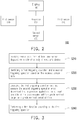
- FIG. 3 is a flow diagram illustrating an operation of electronic device according to one of the exemplary embodiments of the disclosure.
- sensor data is obtained or received from at least one of the first sensor 120 and the second sensor 130.
- the processor 102 based on a sensor data obtained from at least one sensor (first or second sensor 120, 130), the processor 102 would identify whether a grip action is a clamping action (i.e., first triggering operation) or a squeeze action (i.e., second triggering operation), and then trigger the subsequent corresponding function. It should be noted that the identification of a grip action does not require sensor data from both of the first and second sensors.
- sensor data from at least one of the first and second sensors 120, 130 would be sufficient to differentiate a holder grip action from a squeeze action.
- the electronic device may be equipped with a sensor on one side of the body only, the disclosure is not intended to limit the disposition of the sensor. In the following, the characteristic of the squeeze action would be described first, and then the characteristic of the clamping action.
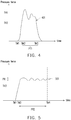
- FIG. 4 is a diagram illustrating a pressing pressure of squeeze action according to one of the exemplary embodiments of the disclosure.
- the curve illustrated in FIG. 4 is an example of the pressure measured by any of the first sensor or the second sensor. Since a user may not keep their force in the same level as one holds (or squeeze or grip) the electronic device, the user's force of squeeze action may not be a curve with constant pressure for a period of time.
- a curve 401 illustrates a pattern of the pressure applied by the squeeze action, which may be a little up and down.
- different thresholds for squeezing and releasing are set. For example, referring to FIG.
- a squeezing threshold TH1 is set for determining if a squeeze action begins (i.e., a second triggering operation), and a releasing threshold TH2 is set for determining if the squeeze action finishes.
- the releasing threshold TH2 is smaller than the squeezing threshold TH1.
- the squeezing threshold TH1 may be set through testing user's squeezing force during a squeezing setting procedure of the portable electronic device 100.
- the releasing threshold TH2 may be set according to the squeezing threshold TH1.
- the squeezing setting procedure may comprise asking the user to squeeze the portable electronic device 100, sensing test pressing forces F1 of user's squeezing the portable electronic device 100 with intention to trigger a functional operation of the portable electronic device 100 for several times, and determining a set pressing force F2 to be the squeezing threshold TH1 according to the test pressing forces F1.
- the set pressing force F2 may be a percentile value of the test pressing forces F1.
- the test pressing forces F1 may be 100, 150, and 200 (pressure units)
- the set pressing force F2 (or the squeezing threshold TH1) is 175 (pressure units) being a percentile value of 75th percentile calculated according to the minimum value of 100 (pressure units) and the maximum value of 200 (pressure units).
- the present disclosure is not limited thereto.
- the test pressing forces F1 may be 100, 150, and 200 (pressure units)
- the set pressing force F2 (or the squeezing threshold TH1) is 150 (pressure units), being an average value of the three test pressing forces F1.
- the releasing threshold TH2 may be determined by the processor 102 according to the squeezing threshold TH1.
- the releasing threshold TH2 may be a specific ratio (smaller than 100%) of the squeezing threshold TH1.
- the value of the releasing threshold TH2 is 75% of the value of the squeezing threshold TH1.
- a time point TM1 represents a start of a squeeze action upon a detection of pressure on at least one side of the body 110 of the electronic device 100.
- a time period PT1 between a time point TM2 (corresponding to the squeezing threshold TH1) and a time point TM3 (corresponding to the releasing threshold TH2) may be determined by the processor 102 as a time period of the squeeze action.
- the squeeze action can be determined by the processor 102 as a long squeeze action or a short squeeze action according to the time period PT1 between the time point TM2 and the time point TM3, comparing to a time threshold (e.g., 0.7s).
- a desired function of the electronic device 100 may be determined by the processor 102 according to the squeeze action.
- FIG. 5 is a diagram illustrating a pressing pressure of clamping action according to one of the exemplary embodiments of the disclosure.
- a pressure detected by a sensor disposed on a side (or edge) of the electronic device 100 may be a curve that has less variation for a period of time, since a jaw of a holder would apply the same amount of force.
- a curve 501 is an example of a pressing pressure measured by any of the first sensor or the second sensor while the electronic device 100 is being held by a holder or stand, where the pressing pressure reflects a pressure being applied to the side of the body by the jaws of a holder.
- a clamping threshold TH3 may be set and configured for the processor 102 to determine whether the detected pressure exceed a certain threshold for it to be considered as a clamping action.
- the exemplary embodiment is not intended to limit the clamping threshold TH3.
- the clamping threshold TH3 may be the same, higher, or lower than the squeezing threshold TH1 or the releasing threshold TH2 as illustrated in FIG. 4 .
- a time point TM1 represents a start of a grip action upon a detection of pressing pressure on at least one side of the body 110 of the electronic device 100.
- data may be sampled for a period of time.
- the pattern of the pressing pressure would have less variations, the variations of the pressing pressure would remain within a predetermined range PR that is considered to be stable or constant for a predetermined period of time PT2, which may also be referred to as a constant pressure.
- the predetermined period of time PT2 is defined to be a period between the time point TM3 to a time point TM4. Therefore, the processor 102 may utilize this characteristic and determine that the electronic device 100 is being held by a holder.
- the predetermined period of time PT2 may be 1us, 5us, 1ms, 5s, or any other amount of time, and the exemplary embodiment is not intended to limit the amount of the sampling time PT2.
- the predetermined range PR of the pressing pressure may be 2, 5, 20 pressure units, or any other pressure units configured by a user, the exemplary embodiment is not intended to limit the value of the predetermined range PR of the pressing pressure.
- the determinations of the grip action depicted in FIGs. 4 and 5 may be performed in parallel or sequentially.
- the pressing pressure of the clamping action would remain within a predetermined range PR for a predetermined period of time PT2.
- the pressing pressure of a clamping action may remain within a certain pressure range for 10 seconds (predetermined period of time PT2), and a difference between max and min peaks of the detected pressing pressure may be within (less or equal to) the predetermined range of the pressure.
- the pressing pressure of a squeeze action may have variations that would result in a difference between the max and min peaks of the detected pressing pressure to be greater than predetermined range of the pressure.
- the processor 102 may differentiate the clamping action from the squeeze action and identifies whether the grip action is a first triggering operation or a second triggering operation.
- the processor 102 executes the first triggering operation which triggers a first function such as a driving mode, map application, etc., and not executing the second triggering operation which triggers a second function corresponding to the squeeze operation, where the first function is different from the second function.
- the clamping action it is also necessary to differentiate the clamping action from a normal grip of the electronic device 100.
- the normal grip may be referred to as a grasp of user's hand.
- the first and second sensors may also sense the presences of objects or pressures when the electronic device is being place is a bag or packet. The differentiation between these grip action and clamping action may be similar above, where the variation of the pressing pressure for a predetermined period of time may be sampled to differentiate the clamping action to the above grip action.
- step S360 the first function would be performed in response to the first triggering operation.
- the pressing pressure of a jaw of a holder or stand (clamping action) would remain within a constant pressure for a period of time as compared to other grip actions. Therefore, in the exemplary embodiment, sensor data from at least one sensor disposed on one side of the body would be sufficient to identify that the electronic device is being held by a holder based on the pressing pressure being applied on that side of the electronic device 100.
- a clamping action may be referred to a situation where the electronic device 100 is securely held or fastened in a position.
- the electronic device 100 may be held by a holder or stands having jaws that clamp to the sides of the electronic device 100 (may also referred to as clamping portion). These jaws may apply constant pressure to particular positions on the first side S1 and second side S2 of the electronic device 100, respectively.
- the processor 102 further identifies a clamping pattern based on the received sensor data.
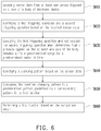
- FIG. 6 is a flow diagram illustrating a process of electronic device for executing a function corresponding to a clamping action according to one of the exemplary embodiments of the disclosure.
- steps S610-S630 are similar to steps S310-S330 illustrated in FIG. 3 , respectively, and detail of which are described above.
- the processor 102 further identify a clamping pattern based on the sensor data (step S640).
- the sensor data includes various information (e.g., position data, pressure data, etc.) that would allow the processing unit 102 to determine the status of the electronic device.
- the position of the object may be obtained or estimated through the location of the activated sensing elements of the first and second sensors 120, 130 along the first and second sides S1, S2 of the electronic device 100.
- the order of the sensing elements may be recorded such as first sensing element of the first side S1, second sensing element of the first side S1, and so on.
- the position of each sensing elements may be recorded in a mapping table by other means.
- the first sensor data and the second sensor data may each includes position and pressure data representing the pressure that is being applied to each position pressed by the object.
- FIG. 7 is a diagram illustrating an electronic device being by a holder according to one of the exemplary embodiment of the disclosure.
- the electronic device 100 is held by a holder 10 having a first clamping portion 11 and a second clamping portion 12.
- the first and second clamping portions 11, 12 of the holder 10 respectively applies pressure inward.
- the first clamping portion 11 clamps to the electronic device 100 at a first position on the first side S1.
- the second clamping portion 12 clamps to the electronic device 100 at a second position on the second side S2.
- the pressure applied through the first and second clamping portions in opposite directions forms a clamping effect that securely holds the electronic device 100 in place.
- the processor 102 identifies the first and second positions on the first and second sides S1, S2 of the electronic device 100 as the clamping pattern that holds the electronic device 100.
- FIG. 8 is a diagram illustrating an electronic device being by a holder according to one of the exemplary embodiment of the disclosure.
- the electronic device 100 is held by a holder 20 having a first clamping portion 21, a second clamping portion 22, and a third clamping portion 23.
- FIG. 8 illustrates that the first clamping portion 21 of the holder 20 clamps to the electronic device 100 at a first position of the first side S1, while the second clamping portion 22 and the third clamping portion 23 respectively clamps to the electronic device 100 at a second portion and a third portion of the second side S2.
- the processor 102 identifies the first, second, and third positions on the first and second sides S1, S2 as the clamping pattern that holds the electronic device 100.
- the position and the number of clamping portion along each of the first and second sides S1, S2 and the position as the clamping pattern is defined by one pressed point on the first side S1, two pressed point on the second side S2, and their respective position on the first and second sides S1, S2.
- the holders 10, 20 illustrated above may be a car holder, a bicycle holder, VR helmet, a selfie stands, and the like. Although two and three clamping portions are utilized above to explain the concept of the disclosure, the number of the clamping portions should not be constituted as a limit to the disclosure.
- the exemplary embodiments illustrated the electronic device are being held in the landscape orientation, however, the disclosure is not limited thereto.
- the electronic device may also be oriented in the portrait orientation, and the determination of clamping action and identification of the clamping pattern would be similar as to the process above.
- step S650 the processor 102 compares the identified clamping pattern to a predetermined pattern which is predefined as a corresponding pattern for a first function.
- a predetermined pattern may be recorded in the electronic device 100, each predetermined pattern may be associated or assigned to a particular function or application program.
- step S660 the processor 102 automatically performs a first function based on a comparison between the identified clamping pattern and predetermined patterns performs, or automatically start or launch an application program corresponding to the identified clamping pattern.
- a car holder may have clamping portions similar to the exemplary embodiment illustrated in FIG. 7 , where one pressed position is sensed on each of the first side S1 and the second side S2.
- the identified clamping pattern may be registered to be associated with a navigation application program through user's configuration or other means ahead of time.
- the electronic device 100 may then launch the navigation application program automatically based on the identified clamping pattern.
- the electronic device 100 may be held by a virtual reality (VR) goggle having three clamping portions similar to the exemplary embodiment illustrated in FIG. 8 , or any other clamping patterns.
- Such clamping pattern may be registered be to associated with a VR application program.
- the processor 102 may automatically launch the VR application program upon a detection of the clamping pattern illustrated in FIG. 8 .
- the processor 102 may further correlate the pressed positions detected on the first and second sides S1, S2 of the electronic device 100. That is, the processor 102 may determine a relationship between each of the pressed positions in distance, and further utilizes the relationship between clamping portions of the holder as one of the parameters to consider for identifying the clamping pattern.
- the pressed positions corresponding to the clamping portions 11, 12 on the first side S1 and second side S2 may be symmetrical in position. That is, the pressed portion caused by the clamping portion 11 along the first side S1 is measured to be at a distance started from the bottom side of the electronic device as the pressed portion caused by the clamping portion 12 along the second side S2.
- the processor 102 may consider this symmetrical relationship between the pressed position of the first and second clamping portion 11, 12 as one of the parameters for identifying the clamping pattern (e.g., a symmetrical clamping action).
- the clamping portions of the VR holder that press the same side of the electronic device 100 may be designed to have a particular distance apart.
- the clamping portion 21 of the holder 20 may not be centered between the clamping portions 22, 23.
- the clamping portion 21 may be closer to the clamping portion 22. Accordingly, the processor 102 may further differentiate such clamping pattern from other patterns, and launches the corresponding application program.
- the predetermined pattern may be automatically learned based on the sensor data or predefined by a user.
- the processor 102 may automatically learn that a clamping pattern may be defined as predetermined pattern if the first and second sensor data indicate that the pressure applied by the holder on both of the first and second sides of the electronic device remain constant for a period of time.
- the processor 102 may automatically associate the detected clamping pattern to the manually started application program or display a message on the display to inquire user's feedback.
- the electronic device 100 may include a memory (not shown) which records the detected clamping pattern.
- the processor 102 in addition to the sensor data obtained from the first and second sensors 120, 130, the processor 102 further considers whether the display 140 is turned on or off upon detection of the clamping action. Upon detection of a constant pressure being applied on one side of the body or a clamping pattern, the processor 102 further determines whether the display is on or off as one of the parameters for determining which function of the electronic device 100 should be performed. For example, the electronic device 100 may be clamped on a car holder. With parameters such as the constant pressure (or clamping pattern) measured from at least one sensor and display being off, the processor 102 may automatically determine that a desire function of the electronic device 100 may be a driving mode application.
- the driving mode application simplifies the operational interface of the electronic device 100, where icons may be enlarged for easier touch operation, speaker enablement, automatic connection to the car system (e.g., audio or video), or the like. Then, based on the sensor data and status of the display 140, the processor 102 may further discover the intention of the user and automatically performs a second function.
- the processor 102 may further utilize a sensor data obtained from the third sensor 150 (e.g., accelerometer) as an additional parameter for discovering the intention of the user and start a third function.
- the third sensor 150 may be an accelerometer which provides acceleration data and heading data.
- the processor 102 Upon detection of a constant pressure being applied on one side of the body or a camping pattern, the processor 102 further determines an orientation of the electronic device 100 by using the sensor data obtained from the third sensor. For example, a landscape orientation and portrait orientation be configured to indicate that a holder be to a car holder or a bicycle holder.
- car and bicycle may use the same holder, however, the orientation of electronic device would be different between car and bicycle.
- the electronic device 100 may be mounted in the landscape orientation in the car environment, whereas the portrait orientation may be desired in the bicycle environment.
- the processor 102 may further define the intention of a user for different environments.
- the operational interface may be different between car and bicycle environments, and thus the function to be perform would be different.
- parameters such as pressing pressure, clamping pattern, status of the display, and orientation of the electronic device are described separately. However, it should be noted that these parameters may be combined in any way for determining a function or application program to start that would better fit the scenario which the electronic device is in.
- the disclosure also provides a non-transitory computer readable recording medium, which records computer program to be loaded into a processor disposed in an electronic device to execute the steps of the proposed method.
- the computer program is composed of a plurality of program instructions (e.g. an organization chart, establishing program instruction, a table approving program instruction, a setting program instruction, and a deployment program instruction). Once the program sections are loaded into the processing device and executed by the same, the steps of the proposed method would be accomplished.
- the exemplary embodiments described above depicted an operating method and an electronic device thereof.
- the electronic device is configured to predict user's next action and automatically start a function, or launch or start an application program without user's input.
- the electronic device detects an occurrence of a clamping action based on sensor data obtained from at least one sensor disposed on one side of the electronic device.
- the electronic device Upon detection of the clamping action, the electronic device automatically launches or starts a function or an application program for clamping action without user's input through a touch display.
- clamping pattern corresponding to the clamping action may be identified based on the sensor data obtained from the first and second sensors to further identify the situation of the electronic device, and accordingly, finer determination of a desired function or application program may be achieved.
- Exemplary embodiments of the present disclosure may comprise any one or more of the novel features described herein, including in the Detailed Description, and/or shown in the drawings. While the foregoing describes a number of separate embodiments of the apparatus and method of the present disclosure, what has been described herein is merely illustrative of the application of the principles of the present disclosure. For example, as used herein various directional and orientation terms such as “vertical”, “horizontal”, “bottom”, “top”, “side”, and the like, are used only as relative conventions and not as absolute orientations with respect to a fixed coordinate system. Note also, as used herein the terms “process” and/or “processor” should be taken broadly to include a variety of electronic hardware and/or software based functions and components.
- any function, process, application, and/or processor here herein can be implemented using electronic hardware, software consisting of a non-transitory computer-readable medium of program instructions, or a combination of hardware and software. Accordingly, this description is meant to be taken only by way of example, and not to otherwise limit the scope of this invention.
- each of the expressions “at least one of A, B and C,” “at least one of A, B, or C,” “one or more of A, B, and C,” “one or more of A, B, or C” and “A, B, and/or C” means A alone, B alone, C alone, A and B together, A and C together, B and C together, or A, B and C together.
- the term “a” or “an” entity refers to one or more of that entity.
- the terms “a” (or “an”), “one or more” and “at least one” can be used interchangeably herein.
Landscapes
- Engineering & Computer Science (AREA)
- General Engineering & Computer Science (AREA)
- Theoretical Computer Science (AREA)
- Human Computer Interaction (AREA)
- Physics & Mathematics (AREA)
- General Physics & Mathematics (AREA)
- Computer Hardware Design (AREA)
- User Interface Of Digital Computer (AREA)
Abstract
Description
- The invention relates a method for operating an electronic device, an electronic device, and a computer-readable recording medium thereof, and more particularly, relates to an electronic device being operated through sensors disposed on the sides of the electronic device.
- Nowadays, electronic devices such as mobile phone, tablet PC and the like are popular and being used in all kind of occasions. For example, one may use the electronic device while driving for navigation, music playing, video recording, etc. Various methods have been developed for operating the electronic device by developers, for examples, touch operations, hand gesture, voice recognition, etc. One would give a commend via touch operation or voice to launch an application program installed on the electronic device as to perform a functional operation.
- Nothing herein should be construed as an admission of knowledge in the prior art of any portion of the present invention. Furthermore, citation or identification of any document in this application is not an admission that such document is available as prior art to the present invention, or that any reference forms a part of the common general knowledge in the art.
- The disclosure is directed to an operating method, an electronic device and a computer-readable recording medium for automatically launching or starting an application program based on sensor data of sensors disposed on at least one side of the electronic device.
- In one of the exemplary embodiments, an electronic device is provided. The electronic device includes a body, at least one sensor and a processor. The body may comprise a back and a front with a display. The at least one sensor is disposed on one side of the body. The processor is coupled to the at least one sensors to receive a sensor data. The processor is configured to identify a first triggering operation and a second triggering operation based on the received sensor data. When determined that a pressure applied on the at least one side of the body remains within a predetermined range for a predetermined period of time, the processor is configured to execute the first triggering operation and not execute the second triggering operation when determined, wherein the first triggering operation is a clamping action, and the second triggering operation is associated to a squeeze action. In response to the first triggering operation, the processor performs a first function (or start an application program).
- According to one of the exemplary embodiments, in response to the first triggering operation, the processor is further configured to identify a clamping pattern based on the sensor data, compare the identified clamping pattern to a predetermined pattern predefined as a corresponding pattern for a first function, and perform the first function based on the comparison result.
- According to one of the exemplary embodiments, the at least one sensor includes a first sensor disposed on a first side of the body and a second sensor disposed on a second side of the body opposite to the first side. In response to the first triggering operation, the processor is further configured to identify a clamping pattern based on the sensor data, compare the identified clamping pattern to a predetermined pattern predefined as a corresponding pattern for a first function, and perform the first function based on the comparison result.
- According to one of the exemplary embodiments, the processor further incorporates information regarding to the status of the display (on or off) for determining a function or application program to perform.
- According to one of the exemplary embodiments, the processor further incorporates information regarding to an accelerometer for determining a function or application program to perform.
- In one of the exemplary embodiments, a method for operating an electronic device is provided, where the electronic device includes at least one sensor disposed on one side of the electronic device, and the method includes the following steps. Sensor data is obtained from the at least one sensor. A first triggering operation and a second triggering operation is identified based on the obtained sensor data. The first triggering operation and not executing the second triggering operation is executed when, determined, based on the sensor data, that a pressure applied on the side of the body remains within a constant range for a predetermined period of time.
- In one of exemplary embodiments, the computer-readable recording medium records computer program to be loaded into a processor in an electronic device to execute the steps of the aforementioned method.
- To make the above features and advantages of the disclosure more comprehensible, several embodiments accompanied with drawings are described in detail as follows.
- It should be understood, however, that this Summary may not contain all of the aspects and embodiments of the present invention, is not meant to be limiting or restrictive in any manner, and that the invention as disclosed herein is and will be understood by those of ordinary skill in the art to encompass obvious improvements and modifications thereto.
- The accompanying drawings are included to provide a further understanding of the invention, and are incorporated in and constitute a part of this specification. The drawings illustrate embodiments of the invention and, together with the description, serve to explain the principles of the invention.
-
FIGs. 1A and1B are a diagram illustrating an electronic device according to one of the exemplary embodiments of the disclosure. -
FIG. 2 is a block diagram illustrating an electronic device according to one of the exemplary embodiment of the disclosure. -
FIG. 3 is a flow diagram illustrating an operation of electronic device according to one of the exemplary embodiments of the disclosure. -
FIG. 4 is a diagram illustrating a pressing pressure of squeeze action according to one of the exemplary embodiments of the disclosure. -
FIG. 5 is a diagram illustrating a pressing pressure of clamping action according to one of the exemplary embodiments of the disclosure. -
FIG. 6 is a flow diagram illustrating a process of electronic device for executing a function corresponding to a clamping action according to one of the exemplary embodiments of the disclosure. -
FIG. 7 is a diagram illustrating an electronic device being by a holder according to one of the exemplary embodiment of the disclosure. -
FIG. 8 is a diagram illustrating an electronic device being by a holder according to one of the exemplary embodiment of the disclosure. - Reference will now be made in detail to the present preferred embodiments of the invention, examples of which are illustrated in the accompanying drawings. Wherever possible, the same reference numbers are used in the drawings and the description to refer to the same or like parts.
- A novel method for operating an electronic device is provided. In the various exemplary embodiments, outputs from at least one sensor disposed on a side of the electronic device, which are also referred to edge sensor, is utilized for triggering functional operations of the electronic device. Through the outputs obtained from the edge sensor, the electronic device predicts user's next desired operation and automatically perform a function by launching or starting an application program installed on the electronic device. Exemplary embodiments are described below to illustrate an electronic device having the edge sensors and operation of the electronic device through the edge sensors.
-
FIGs. 1A and1B are a diagram illustrating anelectronic device 100 according to one of the exemplary embodiments of the disclosure. With reference toFIGs. 1A and1B , theelectronic device 100 includes abody 110, afirst sensor 120, and asecond sensor 130. Thebody 110 includes, in addition to the back and the front with adisplay 140, a first side S1 and a second side S2, where the first side S1 is opposite to the second side S2. Thefirst sensor 120 is disposed on the first side S1 of thebody 110, and thesecond sensor 130 is disposed on the second side of the side S2. However, the exemplary embodiment is not intended to limit the location of the first andsecond sensors second sensors electronic device 100, respectively. According to one embodiment, the electronic device only comprises the at least onesensor -
FIG. 2 is a block diagram illustrating an electronic device according to one of the exemplary embodiment of the disclosure. With reference toFIG. 2 , theelectronic device 100 further includes aprocessor 102, where theprocessor 102 is coupled to thefirst sensor 120 to receive a first sensor data and thesecond sensor 130 to receive a second sensor data. Theprocessor 102 may include one or more processor(s) having generic characteristics similar to general purpose processor, such as a central processor (CPU), or may be application specific integrated circuitry (ASIC) that provides arithmetic and control functions to theelectronic device 100. In some exemplary embodiments, theprocessor 102 may be implemented by executing instructions loaded from a memory (not shown), or logic circuits programmed to provide arithmetic operations. In some exemplary embodiments, theprocessor 102 may be a microprocessor and a digital signal processor (DSP), a programmable controller, a programmable logic device (PLD), other similar devices or a combination of aforementioned devices, where theprocessor 102 is programmed to execute the functions or steps that would be described below. - In some exemplary embodiments, the
electronic device 100 may also include adisplay 140. Thedisplay 140 may include display function and touch sensing function, where thedisplay 140 may be integrated with touch sensors. The touch sensors may be resistive touch sensor, capacitive touch sensor, optic touch sensor or the likes and configured to receive touch operations of fingers, palms, stylus or other objects. - The
first sensor 120 and thesecond sensor 130 may cover a portion or entire side of thebody 110 of theelectronic device 100 and function to detect the presence of objects (e.g., finger, or clamp) being placed on the first and second side S1, S2 of theelectronic device 100, where the position of the object along the first and second side S1, S2 and force or pressure applied by the objects along the first and second side S1, S2 of thebody 110 may be determined, respectively. In the exemplary embodiments, the first andsensor - In some exemplary embodiments, the
first sensor 120 and thesecond sensor 130 each may include a plurality of sensing elements 121(1)-121(n), 131(1)-131(n) that are arranged in an extending direction of the first side S1 or the second side S2 of thebody 110 starting from a bottom side of theelectronic device 100. The disclosure is not intended to limit the number of the sensing elements 121(1)-121(n) being disposed on the first or second side S1, S2 for different types of sensor would require different number of sensing elements for detecting a force being applied thereupon. For example, the capacitive and resistive sensors may require denser distribution of the sensing elements along the first and second sides S1, S2 of thebody 110 as to detect a dimension of the touch area, where the applied force may be determined by the touch area. That is, as the touch area increase, theprocessor 102 may determine that a greater force is being applied as compared to a small touch area. In other exemplary embodiments, the first andsecond sensors processor 102 may determine the force or pressure being applied based on the noise generated by an action of a griping, holding, clamping, etc. The disclosure is not intended to limit the type of the sensors for various type of the sensors may be implemented to obtain information as to embody the exemplary embodiments. - With reference to
FIG. 1 , the sensing elements 121(1)-121(n) may be evenly distributed along the first side S1 of thebody 110. The sensing elements 131(1)-131(n) may be evenly distributed along second side S2 of thebody 110. In one of the exemplary embodiment, the sensing elements 121(1)-121(n) and 131(1)-121(n) are further arranged symmetrically in position between the first and second sides S1, S2 of thebody 110. For example, the sensing elements 121(1) may be positioned along the first side S1 at a similar height (or a distance starting from a bottom edge of the body 110) as the sensing element 131(1) along the second side S2. - With reference to
FIG. 2 , in some exemplary embodiments, theelectronic device 100 may also include athird sensor 150. Thethird sensor 150 may be a g-sensor, a magnetic sensor, an accelerator, or other sensors that provide information regarding to a heading direction of theelectronic device 100. In the exemplary embodiments, sensor data outputted from thethird sensor 150 may be utilized by theprocessor 102 to determine an orientation of the electronic device 100 (landscape or portrait). The sensor data output by thethird sensor 150 may be a direction or an acceleration information toward a particular direction. Based the provided direction, theprocessor 102 may determine the orientation of theelectronic device 100 based on the provided (heading) direction. - In the following, an operating method of the electronic device as to automatically perform a function based on the sensor based on the sensor data obtained from at least one of the first and
second sensors FIGs. 1 and2 . - As described above, the
electronic device 100 detects the presence of objects on the first side S1 or the second side S2 of thebody 110 through the outputs of thefirst sensor 120 and thesecond sensor 130. When objects are detected on both of the first and second sides S1, S2, such situation may be referred to as a grip action. In other words, theelectronic device 100 is being held by user's hand or by a holder (also referred to as stand). - In one of the exemplary embodiments, the electronic device may differentiate a clamping action from a squeeze action based on the sensor data, as to accurately trigger a desired function of the
electronic device 100. The clamping action refers to a grip action performed by a holder, a stand, etc. Theprocessor 102 would identify a pattern of the sensor data corresponding to the clamping action as a first triggering operation. The squeeze action refers to a grip action performed by user's hand, where the user may intentionally apply pressure to trigger various functions of theelectronic device 100, or it may be a normal grip or holding of theelectronic device 100. Theprocessor 102 may identify a pattern of the sensor data corresponding to the squeeze action as a second triggering operation. -
FIG. 3 is a flow diagram illustrating an operation of electronic device according to one of the exemplary embodiments of the disclosure. In step S310, sensor data is obtained or received from at least one of thefirst sensor 120 and thesecond sensor 130. In step S320, based on a sensor data obtained from at least one sensor (first orsecond sensor 120, 130), theprocessor 102 would identify whether a grip action is a clamping action (i.e., first triggering operation) or a squeeze action (i.e., second triggering operation), and then trigger the subsequent corresponding function. It should be noted that the identification of a grip action does not require sensor data from both of the first and second sensors. In one of the exemplary embodiments, sensor data from at least one of the first andsecond sensors -
FIG. 4 is a diagram illustrating a pressing pressure of squeeze action according to one of the exemplary embodiments of the disclosure. The curve illustrated inFIG. 4 is an example of the pressure measured by any of the first sensor or the second sensor. Since a user may not keep their force in the same level as one holds (or squeeze or grip) the electronic device, the user's force of squeeze action may not be a curve with constant pressure for a period of time. For example, acurve 401 illustrates a pattern of the pressure applied by the squeeze action, which may be a little up and down. In order to improve the successful rate of determining whether the squeeze action is performed, different thresholds for squeezing and releasing are set. For example, referring toFIG. 4 , a squeezing threshold TH1 is set for determining if a squeeze action begins (i.e., a second triggering operation), and a releasing threshold TH2 is set for determining if the squeeze action finishes. The releasing threshold TH2 is smaller than the squeezing threshold TH1. - The squeezing threshold TH1 may be set through testing user's squeezing force during a squeezing setting procedure of the portable
electronic device 100. The releasing threshold TH2 may be set according to the squeezing threshold TH1. The squeezing setting procedure may comprise asking the user to squeeze the portableelectronic device 100, sensing test pressing forces F1 of user's squeezing the portableelectronic device 100 with intention to trigger a functional operation of the portableelectronic device 100 for several times, and determining a set pressing force F2 to be the squeezing threshold TH1 according to the test pressing forces F1. - The set pressing force F2 may be a percentile value of the test pressing forces F1. For example, in one of the exemplary embodiments, the test pressing forces F1 may be 100, 150, and 200 (pressure units), and the set pressing force F2 (or the squeezing threshold TH1) is 175 (pressure units) being a percentile value of 75th percentile calculated according to the minimum value of 100 (pressure units) and the maximum value of 200 (pressure units). The present disclosure is not limited thereto. In another embodiment, for example, the test pressing forces F1 may be 100, 150, and 200 (pressure units), and the set pressing force F2 (or the squeezing threshold TH1) is 150 (pressure units), being an average value of the three test pressing forces F1.
- The releasing threshold TH2 may be determined by the
processor 102 according to the squeezing threshold TH1. In an embodiment, the releasing threshold TH2 may be a specific ratio (smaller than 100%) of the squeezing threshold TH1. For example, the value of the releasing threshold TH2 is 75% of the value of the squeezing threshold TH1. - In
FIG. 4 , a time point TM1 represents a start of a squeeze action upon a detection of pressure on at least one side of thebody 110 of theelectronic device 100. A time period PT1 between a time point TM2 (corresponding to the squeezing threshold TH1) and a time point TM3 (corresponding to the releasing threshold TH2) may be determined by theprocessor 102 as a time period of the squeeze action. The squeeze action can be determined by theprocessor 102 as a long squeeze action or a short squeeze action according to the time period PT1 between the time point TM2 and the time point TM3, comparing to a time threshold (e.g., 0.7s). According to the time period of the squeeze action (the long squeeze action or the short squeeze action), a desired function of theelectronic device 100 may be determined by theprocessor 102 according to the squeeze action. - In the following, the characteristic of the clamping action is described.
FIG. 5 is a diagram illustrating a pressing pressure of clamping action according to one of the exemplary embodiments of the disclosure. Different from the squeeze action, a pressure detected by a sensor disposed on a side (or edge) of theelectronic device 100 may be a curve that has less variation for a period of time, since a jaw of a holder would apply the same amount of force. - With reference to
FIG. 5 , acurve 501 is an example of a pressing pressure measured by any of the first sensor or the second sensor while theelectronic device 100 is being held by a holder or stand, where the pressing pressure reflects a pressure being applied to the side of the body by the jaws of a holder. In the exemplary embodiment, a clamping threshold TH3 may be set and configured for theprocessor 102 to determine whether the detected pressure exceed a certain threshold for it to be considered as a clamping action. The exemplary embodiment is not intended to limit the clamping threshold TH3. In other exemplary embodiments, the clamping threshold TH3 may be the same, higher, or lower than the squeezing threshold TH1 or the releasing threshold TH2 as illustrated inFIG. 4 . - Similar to
FIG. 4 , a time point TM1 represents a start of a grip action upon a detection of pressing pressure on at least one side of thebody 110 of theelectronic device 100. Upon detection of the pressing pressure rising about the clamping threshold TH3 at a time point TM3, data may be sampled for a period of time. For the clamping action, the pattern of the pressing pressure would have less variations, the variations of the pressing pressure would remain within a predetermined range PR that is considered to be stable or constant for a predetermined period of time PT2, which may also be referred to as a constant pressure. The predetermined period of time PT2 is defined to be a period between the time point TM3 to a time point TM4. Therefore, theprocessor 102 may utilize this characteristic and determine that theelectronic device 100 is being held by a holder. - The predetermined period of time PT2 may be 1us, 5us, 1ms, 5s, or any other amount of time, and the exemplary embodiment is not intended to limit the amount of the sampling time PT2. Furthermore, the predetermined range PR of the pressing pressure may be 2, 5, 20 pressure units, or any other pressure units configured by a user, the exemplary embodiment is not intended to limit the value of the predetermined range PR of the pressing pressure.
- It should be noted that the determinations of the grip action depicted in
FIGs. 4 and 5 may be performed in parallel or sequentially. One of the differences is that the pressing pressure of the clamping action would remain within a predetermined range PR for a predetermined period of time PT2. For example, the pressing pressure of a clamping action may remain within a certain pressure range for 10 seconds (predetermined period of time PT2), and a difference between max and min peaks of the detected pressing pressure may be within (less or equal to) the predetermined range of the pressure. On the other hand, the pressing pressure of a squeeze action may have variations that would result in a difference between the max and min peaks of the detected pressing pressure to be greater than predetermined range of the pressure. - Based on the above, the
processor 102 may differentiate the clamping action from the squeeze action and identifies whether the grip action is a first triggering operation or a second triggering operation. In step S330, theprocessor 102 executes the first triggering operation which triggers a first function such as a driving mode, map application, etc., and not executing the second triggering operation which triggers a second function corresponding to the squeeze operation, where the first function is different from the second function. - In some exemplary embodiments, it is also necessary to differentiate the clamping action from a normal grip of the
electronic device 100. The normal grip may be referred to as a grasp of user's hand. In some situations, the first and second sensors may also sense the presences of objects or pressures when the electronic device is being place is a bag or packet. The differentiation between these grip action and clamping action may be similar above, where the variation of the pressing pressure for a predetermined period of time may be sampled to differentiate the clamping action to the above grip action. - In step S360, the first function would be performed in response to the first triggering operation. As described above, the pressing pressure of a jaw of a holder or stand (clamping action) would remain within a constant pressure for a period of time as compared to other grip actions. Therefore, in the exemplary embodiment, sensor data from at least one sensor disposed on one side of the body would be sufficient to identify that the electronic device is being held by a holder based on the pressing pressure being applied on that side of the
electronic device 100. - From other perspective, a clamping action may be referred to a situation where the
electronic device 100 is securely held or fastened in a position. For example, theelectronic device 100 may be held by a holder or stands having jaws that clamp to the sides of the electronic device 100 (may also referred to as clamping portion). These jaws may apply constant pressure to particular positions on the first side S1 and second side S2 of theelectronic device 100, respectively. In other exemplary embodiments, theprocessor 102 further identifies a clamping pattern based on the received sensor data. -
FIG. 6 is a flow diagram illustrating a process of electronic device for executing a function corresponding to a clamping action according to one of the exemplary embodiments of the disclosure. With reference toFIG. 6 , steps S610-S630 are similar to steps S310-S330 illustrated inFIG. 3 , respectively, and detail of which are described above. In the exemplary embodiment, theprocessor 102 further identify a clamping pattern based on the sensor data (step S640). As described above, the sensor data includes various information (e.g., position data, pressure data, etc.) that would allow theprocessing unit 102 to determine the status of the electronic device. The position of the object may be obtained or estimated through the location of the activated sensing elements of the first andsecond sensors electronic device 100. For example, the order of the sensing elements may be recorded such as first sensing element of the first side S1, second sensing element of the first side S1, and so on. Alternatively, the position of each sensing elements may be recorded in a mapping table by other means. In some exemplary embodiments, the first sensor data and the second sensor data may each includes position and pressure data representing the pressure that is being applied to each position pressed by the object. -
FIG. 7 is a diagram illustrating an electronic device being by a holder according to one of the exemplary embodiment of the disclosure. With reference toFIG. 7 , theelectronic device 100 is held by aholder 10 having afirst clamping portion 11 and asecond clamping portion 12. The first andsecond clamping portions holder 10 respectively applies pressure inward. Thefirst clamping portion 11 clamps to theelectronic device 100 at a first position on the first side S1. Thesecond clamping portion 12 clamps to theelectronic device 100 at a second position on the second side S2. The pressure applied through the first and second clamping portions in opposite directions forms a clamping effect that securely holds theelectronic device 100 in place. In the exemplary embodiment, theprocessor 102 identifies the first and second positions on the first and second sides S1, S2 of theelectronic device 100 as the clamping pattern that holds theelectronic device 100. -
FIG. 8 is a diagram illustrating an electronic device being by a holder according to one of the exemplary embodiment of the disclosure. With reference toFIG. 8 , theelectronic device 100 is held by a holder 20 having afirst clamping portion 21, asecond clamping portion 22, and athird clamping portion 23.FIG. 8 illustrates that thefirst clamping portion 21 of the holder 20 clamps to theelectronic device 100 at a first position of the first side S1, while thesecond clamping portion 22 and thethird clamping portion 23 respectively clamps to theelectronic device 100 at a second portion and a third portion of the second side S2. Theprocessor 102 identifies the first, second, and third positions on the first and second sides S1, S2 as the clamping pattern that holds theelectronic device 100. In the exemplary embodiment, the position and the number of clamping portion along each of the first and second sides S1, S2 and the position as the clamping pattern. That is, the clamping pattern illustrated inFIG. 6 is defined by one pressed point on the first side S1, two pressed point on the second side S2, and their respective position on the first and second sides S1, S2. - The
holders 10, 20 illustrated above may be a car holder, a bicycle holder, VR helmet, a selfie stands, and the like. Although two and three clamping portions are utilized above to explain the concept of the disclosure, the number of the clamping portions should not be constituted as a limit to the disclosure. - Furthermore, the exemplary embodiments illustrated the electronic device are being held in the landscape orientation, however, the disclosure is not limited thereto. The electronic device may also be oriented in the portrait orientation, and the determination of clamping action and identification of the clamping pattern would be similar as to the process above.
- Next, in step S650, the
processor 102 compares the identified clamping pattern to a predetermined pattern which is predefined as a corresponding pattern for a first function. In the exemplary embodiment, a plurality of predetermined patterns may be recorded in theelectronic device 100, each predetermined pattern may be associated or assigned to a particular function or application program. Then, in step S660, theprocessor 102 automatically performs a first function based on a comparison between the identified clamping pattern and predetermined patterns performs, or automatically start or launch an application program corresponding to the identified clamping pattern. - For example, a car holder may have clamping portions similar to the exemplary embodiment illustrated in
FIG. 7 , where one pressed position is sensed on each of the first side S1 and the second side S2. The identified clamping pattern may be registered to be associated with a navigation application program through user's configuration or other means ahead of time. Theelectronic device 100 may then launch the navigation application program automatically based on the identified clamping pattern. - In other exemplary embodiments, the
electronic device 100 may be held by a virtual reality (VR) goggle having three clamping portions similar to the exemplary embodiment illustrated inFIG. 8 , or any other clamping patterns. Such clamping pattern may be registered be to associated with a VR application program. Thus, upon a detection of the clamping pattern illustrated inFIG. 8 , theprocessor 102 may automatically launch the VR application program. - In one of the exemplary embodiments, for the identification of the clamping pattern, the
processor 102 may further correlate the pressed positions detected on the first and second sides S1, S2 of theelectronic device 100. That is, theprocessor 102 may determine a relationship between each of the pressed positions in distance, and further utilizes the relationship between clamping portions of the holder as one of the parameters to consider for identifying the clamping pattern. - Taking the embodiment illustrated in
FIG. 7 as example, the pressed positions corresponding to the clampingportions portion 11 along the first side S1 is measured to be at a distance started from the bottom side of the electronic device as the pressed portion caused by the clampingportion 12 along the second side S2. In this scenario, theprocessor 102 may consider this symmetrical relationship between the pressed position of the first andsecond clamping portion - In some exemplary embodiments, the clamping portions of the VR holder that press the same side of the
electronic device 100 may be designed to have a particular distance apart. In some exemplary embodiments, the clampingportion 21 of the holder 20 may not be centered between the clampingportions portion 21 may be closer to the clampingportion 22. Accordingly, theprocessor 102 may further differentiate such clamping pattern from other patterns, and launches the corresponding application program. - In some exemplary embodiments, the predetermined pattern may be automatically learned based on the sensor data or predefined by a user. For examples, the
processor 102 may automatically learn that a clamping pattern may be defined as predetermined pattern if the first and second sensor data indicate that the pressure applied by the holder on both of the first and second sides of the electronic device remain constant for a period of time. Upon a manual start of an application program by the user, theprocessor 102 may automatically associate the detected clamping pattern to the manually started application program or display a message on the display to inquire user's feedback. Theelectronic device 100 may include a memory (not shown) which records the detected clamping pattern. - In one of the exemplary embodiments, in addition to the sensor data obtained from the first and
second sensors processor 102 further considers whether thedisplay 140 is turned on or off upon detection of the clamping action. Upon detection of a constant pressure being applied on one side of the body or a clamping pattern, theprocessor 102 further determines whether the display is on or off as one of the parameters for determining which function of theelectronic device 100 should be performed. For example, theelectronic device 100 may be clamped on a car holder. With parameters such as the constant pressure (or clamping pattern) measured from at least one sensor and display being off, theprocessor 102 may automatically determine that a desire function of theelectronic device 100 may be a driving mode application. The driving mode application simplifies the operational interface of theelectronic device 100, where icons may be enlarged for easier touch operation, speaker enablement, automatic connection to the car system (e.g., audio or video), or the like. Then, based on the sensor data and status of thedisplay 140, theprocessor 102 may further discover the intention of the user and automatically performs a second function. - In one of the exemplary embodiments, in addition to the sensor data obtained from the first and second sensors, the
processor 102 may further utilize a sensor data obtained from the third sensor 150 (e.g., accelerometer) as an additional parameter for discovering the intention of the user and start a third function. As described above, thethird sensor 150 may be an accelerometer which provides acceleration data and heading data. Upon detection of a constant pressure being applied on one side of the body or a camping pattern, theprocessor 102 further determines an orientation of theelectronic device 100 by using the sensor data obtained from the third sensor. For example, a landscape orientation and portrait orientation be configured to indicate that a holder be to a car holder or a bicycle holder. From other perspectives, car and bicycle may use the same holder, however, the orientation of electronic device would be different between car and bicycle. For example, theelectronic device 100 may be mounted in the landscape orientation in the car environment, whereas the portrait orientation may be desired in the bicycle environment. Accordingly, with the additional data obtained from the accelerometer, theprocessor 102 may further define the intention of a user for different environments. In the exemplary embodiment, the operational interface may be different between car and bicycle environments, and thus the function to be perform would be different. - In the above, parameters such as pressing pressure, clamping pattern, status of the display, and orientation of the electronic device are described separately. However, it should be noted that these parameters may be combined in any way for determining a function or application program to start that would better fit the scenario which the electronic device is in.
- The disclosure also provides a non-transitory computer readable recording medium, which records computer program to be loaded into a processor disposed in an electronic device to execute the steps of the proposed method. The computer program is composed of a plurality of program instructions (e.g. an organization chart, establishing program instruction, a table approving program instruction, a setting program instruction, and a deployment program instruction). Once the program sections are loaded into the processing device and executed by the same, the steps of the proposed method would be accomplished.
- In summary, the exemplary embodiments described above depicted an operating method and an electronic device thereof. The electronic device is configured to predict user's next action and automatically start a function, or launch or start an application program without user's input. The electronic device detects an occurrence of a clamping action based on sensor data obtained from at least one sensor disposed on one side of the electronic device. Upon detection of the clamping action, the electronic device automatically launches or starts a function or an application program for clamping action without user's input through a touch display. Further, clamping pattern corresponding to the clamping action may be identified based on the sensor data obtained from the first and second sensors to further identify the situation of the electronic device, and accordingly, finer determination of a desired function or application program may be achieved.
- Exemplary embodiments of the present disclosure may comprise any one or more of the novel features described herein, including in the Detailed Description, and/or shown in the drawings. While the foregoing describes a number of separate embodiments of the apparatus and method of the present disclosure, what has been described herein is merely illustrative of the application of the principles of the present disclosure. For example, as used herein various directional and orientation terms such as "vertical", "horizontal", "bottom", "top", "side", and the like, are used only as relative conventions and not as absolute orientations with respect to a fixed coordinate system. Note also, as used herein the terms "process" and/or "processor" should be taken broadly to include a variety of electronic hardware and/or software based functions and components. Moreover, a depicted process or processor can be combined with other processes and/or processors or divided into various sub-processes or processors. Such sub-processes and/or sub-processors can be variously combined according to embodiments herein. Likewise, it is expressly contemplated that any function, process, application, and/or processor here herein can be implemented using electronic hardware, software consisting of a non-transitory computer-readable medium of program instructions, or a combination of hardware and software. Accordingly, this description is meant to be taken only by way of example, and not to otherwise limit the scope of this invention.
- Furthermore, as used herein, "at least one," "one or more" and "and/or" are open-ended expressions that are both conjunctive and disjunctive in operation. For example, each of the expressions "at least one of A, B and C," "at least one of A, B, or C," "one or more of A, B, and C," "one or more of A, B, or C" and "A, B, and/or C" means A alone, B alone, C alone, A and B together, A and C together, B and C together, or A, B and C together. It is to be noted that the term "a" or "an" entity refers to one or more of that entity. As such, the terms "a" (or "an"), "one or more" and "at least one" can be used interchangeably herein.
- It will be apparent to those skilled in the art that various modifications and variations can be made to the structure of the present invention without departing from the scope or spirit of the invention. In view of the foregoing, it is intended that the present invention cover modifications and variations of this invention provided they fall within the scope of the following claims and their equivalents.
Claims (15)
- An electronic device, comprising:a body (110) comprising a back and a front with a display (140);at least one sensor (120, 130), disposed on at least one side (S1, S2) of the body; anda processor (102), coupled to the at least one sensor to receive a sensor data, and configured to:identify a first triggering operation and a second triggering operation based on the received sensor data;execute the first triggering operation and not execute the second triggering operation when determined, based on the sensor data, that a pressure applied on the at least one side of the body remains within a predetermined range for a predetermined period of time.
- The electronic device according to claim 1, wherein, in response to the first triggering operation, the processor is further configured to:identify a clamping pattern based on the sensor data;compare the clamping pattern identified to a predetermined pattern predefined as a corresponding pattern for a first function; andperform the first function based on the comparison result.
- The electronic device according to claim 2, wherein the clamping pattern is identified based on a pressed position or the number of the pressed position detected on the at least one side of the body through the at least one sensor data.
- The electronic device according to any one of claim 1-3, wherein the at least one sensor comprises a first sensor disposed on a first side of the body and a second sensor disposed on a second side of the body opposite to the first side, and
wherein the processor is further configured to detect a first pressed position corresponding to a grip of an object applied on the first side of the body through the first sensor, and to detect a second pressed position corresponding to a grip of other object applied on the second side of the body through the second sensor. - The electronic device of claim 4, wherein the predetermined pattern is a grip pattern that is symmetrical between the first and second sides of the body.
- The electronic device according to claim 4, wherein the clamping pattern is identified based on the number of the first pressed position detected on the first side of the body and the number of the second pressed position detected on the second side of the body.
- The electronic device according to any one of claim 1, wherein the second triggering operation is associated to a squeeze action.
- The electronic device according to any one of claim 1-3, wherein the at least one sensor is at least one of capacitive sensor, resistive sensor, optical sensor, piezoelectric sensor, or a combination thereof,
wherein the at least one sensor comprising a plurality of sensing elements arranged along the at least one side of the body, and
wherein the processor detects the occurrence of the first triggering operation when the pressure obtained from the at least one sensors exceeds a predetermined threshold for a period of time. - A method for operating an electronic device, wherein the electronic device comprises a body (110) comprising a back and a front with a display (140), at least one sensor (120, 130) disposed on a side (S1, S2) of the body, comprising:obtaining a sensor data;identifying a first triggering operation and a second triggering operation based on the obtained sensor data;executing the first triggering operation and not executing the second triggering operation when, determined, based on the sensor data, that a pressure applied on the side of the body remains within a constant range for a predetermined period of time.
- The method according to claim 9, wherein, in response to the first triggering operation, the method further comprising:identifying a clamping pattern based on the sensor data;comparing the identified clamping pattern identified to a predetermined pattern predefined as a corresponding pattern for a function;performing a first function based on the comparison result.
- The method according to claim 10, wherein the clamping pattern is identified based on a pressed position or the number of the pressed position detected on the at least one side of the body through the at least one sensor data.
- The method according to claim 9, wherein the at least one sensor comprises a first sensor disposed on a first side of the body and a second sensor disposed on a second side of the body opposite to the first side, and wherein the method further comprises:detecting first pressed position corresponding to a grip of an object applied on the first side of the body through the first sensor; anddetecting a second pressed position corresponding to a grip of other object applied on the second side of the body through the second sensor.
- The method according to any one of claim 9, further comprising:determining whether a display of the electronic device is off in response to the first triggering operation; andperforming a second function when determined that the display is off.
- The method according to any one of claim 9, further comprising:determining an orientation of the electronic device based on a sensor data obtained from a third sensor in response to the first triggering operation; andperforming a third function based on the determined orientation.
- A non-transitory computer readable recording medium, recording a program to be loaded into an electronic device to execute the method for operating the electronic device according to any one of claims 9 to 14.
Applications Claiming Priority (1)
| Application Number | Priority Date | Filing Date | Title |
|---|---|---|---|
| US15/725,298 US10824242B2 (en) | 2017-10-05 | 2017-10-05 | Method for operating electronic device, electronic device and computer-readable recording medium thereof |
Publications (2)
| Publication Number | Publication Date |
|---|---|
| EP3467632A1 true EP3467632A1 (en) | 2019-04-10 |
| EP3467632B1 EP3467632B1 (en) | 2021-02-24 |
Family
ID=60673442
Family Applications (1)
| Application Number | Title | Priority Date | Filing Date |
|---|---|---|---|
| EP17203762.4A Active EP3467632B1 (en) | 2017-10-05 | 2017-11-27 | Method for operating electronic device, electronic device and computer-readable recording medium thereof |
Country Status (4)
| Country | Link |
|---|---|
| US (1) | US10824242B2 (en) |
| EP (1) | EP3467632B1 (en) |
| CN (1) | CN109614029B (en) |
| TW (1) | TWI664557B (en) |
Families Citing this family (3)
| Publication number | Priority date | Publication date | Assignee | Title |
|---|---|---|---|---|
| US11089446B2 (en) * | 2018-01-11 | 2021-08-10 | Htc Corporation | Portable electronic device, operating method for the same, and non-transitory computer readable recording medium |
| TWI669636B (en) * | 2018-06-07 | 2019-08-21 | 宏碁股份有限公司 | Electronic device applicable to interaction control |
| WO2021174341A1 (en) | 2020-03-06 | 2021-09-10 | Boréas Technologies Inc. | Mechanical integration of buttons for piezo-electric actuators |
Citations (3)
| Publication number | Priority date | Publication date | Assignee | Title |
|---|---|---|---|---|
| US20100007618A1 (en) * | 2008-07-09 | 2010-01-14 | Samsung Electronics Co., Ltd | Method and apparatus to use a user interface |
| US20140123003A1 (en) * | 2012-10-29 | 2014-05-01 | Lg Electronics Inc. | Mobile terminal |
| US20150160770A1 (en) * | 2013-12-05 | 2015-06-11 | Lenovo (Singapore) Pte. Ltd. | Contact signature control of device |
Family Cites Families (13)
| Publication number | Priority date | Publication date | Assignee | Title |
|---|---|---|---|---|
| KR101561703B1 (en) | 2009-06-08 | 2015-10-30 | 엘지전자 주식회사 | The method for executing menu and mobile terminal using the same |
| US8907897B2 (en) | 2009-06-16 | 2014-12-09 | Intel Corporation | Optical capacitive thumb control with pressure sensor |
| KR20110031797A (en) * | 2009-09-21 | 2011-03-29 | 삼성전자주식회사 | Input device and method of mobile terminal |
| US8860672B2 (en) * | 2010-05-26 | 2014-10-14 | T-Mobile Usa, Inc. | User interface with z-axis interaction |
| TWI464635B (en) | 2010-12-13 | 2014-12-11 | Inventec Corp | Portable electronic device and control method of the same |
| US20130300668A1 (en) * | 2012-01-17 | 2013-11-14 | Microsoft Corporation | Grip-Based Device Adaptations |
| TWI614668B (en) | 2012-12-21 | 2018-02-11 | 國立成功大學 | Chord input method for hand-hold apparatus combined with virtual interface and physical buttons and hand-hold apparatus using the same |
| EP2816442B1 (en) | 2013-06-20 | 2019-07-31 | Samsung Electronics Co., Ltd | Electronic device and method of controlling electronic device using grip sensing |
| US20150205400A1 (en) | 2014-01-21 | 2015-07-23 | Microsoft Corporation | Grip Detection |
| CN105094593A (en) | 2015-05-22 | 2015-11-25 | 努比亚技术有限公司 | Electronic device and information processing method |
| CN104850261A (en) | 2015-05-28 | 2015-08-19 | 努比亚技术有限公司 | Device end and control method based on device end |
| CN104898926B (en) | 2015-05-29 | 2018-04-27 | 努比亚技术有限公司 | The screenshot method and device of mobile terminal |
| CN105892886B (en) | 2016-03-31 | 2019-03-05 | 维沃移动通信有限公司 | A kind of mobile terminal and control method of mobile terminal |
-
2017
- 2017-10-05 US US15/725,298 patent/US10824242B2/en active Active
- 2017-11-27 EP EP17203762.4A patent/EP3467632B1/en active Active
- 2017-11-30 TW TW106141794A patent/TWI664557B/en active
-
2018
- 2018-01-11 CN CN201810026083.XA patent/CN109614029B/en active Active
Patent Citations (3)
| Publication number | Priority date | Publication date | Assignee | Title |
|---|---|---|---|---|
| US20100007618A1 (en) * | 2008-07-09 | 2010-01-14 | Samsung Electronics Co., Ltd | Method and apparatus to use a user interface |
| US20140123003A1 (en) * | 2012-10-29 | 2014-05-01 | Lg Electronics Inc. | Mobile terminal |
| US20150160770A1 (en) * | 2013-12-05 | 2015-06-11 | Lenovo (Singapore) Pte. Ltd. | Contact signature control of device |
Also Published As
| Publication number | Publication date |
|---|---|
| EP3467632B1 (en) | 2021-02-24 |
| US10824242B2 (en) | 2020-11-03 |
| TWI664557B (en) | 2019-07-01 |
| CN109614029A (en) | 2019-04-12 |
| CN109614029B (en) | 2021-09-07 |
| US20190107899A1 (en) | 2019-04-11 |
| TW201915667A (en) | 2019-04-16 |
Similar Documents
| Publication | Publication Date | Title |
|---|---|---|
| CN106325467B (en) | Method, device and mobile terminal for controlling mobile terminal | |
| JP6420486B2 (en) | Techniques for distinguishing between intended and unintended gestures on a wearable touch-sensing fabric | |
| US8996333B2 (en) | Information processing apparatus which executes specific processing based on a specific condition and a detected specific vibration, and method for controlling the same | |
| US10824242B2 (en) | Method for operating electronic device, electronic device and computer-readable recording medium thereof | |
| CN109565529B (en) | Application startup method and terminal device | |
| EP3124368B1 (en) | Method and device for making a balancing transporter stay-put | |
| US20090265671A1 (en) | Mobile devices with motion gesture recognition | |
| US20150193193A1 (en) | Gesture-controlled tabletop speaker system | |
| JP2007531934A5 (en) | ||
| CN106030494A (en) | Proximity Sensor Based Interaction | |
| US20150160770A1 (en) | Contact signature control of device | |
| JP2008503816A (en) | Electronic device control | |
| US8941623B2 (en) | Methods and devices for determining user input location based on device support configuration | |
| EP1686778A1 (en) | Motion-based sound setting apparatus and method and motion-based sound generating apparatus and method | |
| JP2006139537A (en) | Portable terminal, and operation method for portable terminal | |
| US10222862B2 (en) | Method to sense force exertion on handheld device for behavior setting and input for quick response | |
| CN108089729A (en) | Terminal and its method for realizing reading posture detection | |
| JP2016181047A5 (en) | ||
| WO2016139798A1 (en) | Input detection method, input detection program, and device | |
| JP2012022579A (en) | Face direction detector, face direction detection program and face direction detection method | |
| TWI670629B (en) | Portable electronic device, operating method for the same, and non-transitory computer readable recording medium | |
| EP3214533B1 (en) | Method and terminal for moving screen interface | |
| CN111290638B (en) | Writing input device and writing input system | |
| CN105205421A (en) | Method for detecting taking of portable device | |
| JP6684393B2 (en) | Mobile terminal, program executed by mobile terminal, calibration system, and calibration method |
Legal Events
| Date | Code | Title | Description |
|---|---|---|---|
| PUAI | Public reference made under article 153(3) epc to a published international application that has entered the european phase |
Free format text: ORIGINAL CODE: 0009012 |
|
| STAA | Information on the status of an ep patent application or granted ep patent |
Free format text: STATUS: REQUEST FOR EXAMINATION WAS MADE |
|
| 17P | Request for examination filed |
Effective date: 20171127 |
|
| AK | Designated contracting states |
Kind code of ref document: A1 Designated state(s): AL AT BE BG CH CY CZ DE DK EE ES FI FR GB GR HR HU IE IS IT LI LT LU LV MC MK MT NL NO PL PT RO RS SE SI SK SM TR |
|
| AX | Request for extension of the european patent |
Extension state: BA ME |
|
| RBV | Designated contracting states (corrected) |
Designated state(s): AL AT BE BG CH CY CZ DE DK EE ES FI FR GB GR HR HU IE IS IT LI LT LU LV MC MK MT NL NO PL PT RO RS SE SI SK SM TR |
|
| STAA | Information on the status of an ep patent application or granted ep patent |
Free format text: STATUS: EXAMINATION IS IN PROGRESS |
|
| 17Q | First examination report despatched |
Effective date: 20200330 |
|
| GRAP | Despatch of communication of intention to grant a patent |
Free format text: ORIGINAL CODE: EPIDOSNIGR1 |
|
| STAA | Information on the status of an ep patent application or granted ep patent |
Free format text: STATUS: GRANT OF PATENT IS INTENDED |
|
| INTG | Intention to grant announced |
Effective date: 20200930 |
|
| GRAS | Grant fee paid |
Free format text: ORIGINAL CODE: EPIDOSNIGR3 |
|
| GRAA | (expected) grant |
Free format text: ORIGINAL CODE: 0009210 |
|
| STAA | Information on the status of an ep patent application or granted ep patent |
Free format text: STATUS: THE PATENT HAS BEEN GRANTED |
|
| AK | Designated contracting states |
Kind code of ref document: B1 Designated state(s): AL AT BE BG CH CY CZ DE DK EE ES FI FR GB GR HR HU IE IS IT LI LT LU LV MC MK MT NL NO PL PT RO RS SE SI SK SM TR |
|
| REG | Reference to a national code |
Ref country code: CH Ref legal event code: EP |
|
| REG | Reference to a national code |
Ref country code: AT Ref legal event code: REF Ref document number: 1365315 Country of ref document: AT Kind code of ref document: T Effective date: 20210315 |
|
| REG | Reference to a national code |
Ref country code: IE Ref legal event code: FG4D |
|
| REG | Reference to a national code |
Ref country code: DE Ref legal event code: R096 Ref document number: 602017033143 Country of ref document: DE |
|
| REG | Reference to a national code |
Ref country code: NL Ref legal event code: FP |
|
| REG | Reference to a national code |
Ref country code: LT Ref legal event code: MG9D |
|
| PG25 | Lapsed in a contracting state [announced via postgrant information from national office to epo] |
Ref country code: GR Free format text: LAPSE BECAUSE OF FAILURE TO SUBMIT A TRANSLATION OF THE DESCRIPTION OR TO PAY THE FEE WITHIN THE PRESCRIBED TIME-LIMIT Effective date: 20210525 Ref country code: HR Free format text: LAPSE BECAUSE OF FAILURE TO SUBMIT A TRANSLATION OF THE DESCRIPTION OR TO PAY THE FEE WITHIN THE PRESCRIBED TIME-LIMIT Effective date: 20210224 Ref country code: FI Free format text: LAPSE BECAUSE OF FAILURE TO SUBMIT A TRANSLATION OF THE DESCRIPTION OR TO PAY THE FEE WITHIN THE PRESCRIBED TIME-LIMIT Effective date: 20210224 Ref country code: PT Free format text: LAPSE BECAUSE OF FAILURE TO SUBMIT A TRANSLATION OF THE DESCRIPTION OR TO PAY THE FEE WITHIN THE PRESCRIBED TIME-LIMIT Effective date: 20210624 Ref country code: NO Free format text: LAPSE BECAUSE OF FAILURE TO SUBMIT A TRANSLATION OF THE DESCRIPTION OR TO PAY THE FEE WITHIN THE PRESCRIBED TIME-LIMIT Effective date: 20210524 Ref country code: BG Free format text: LAPSE BECAUSE OF FAILURE TO SUBMIT A TRANSLATION OF THE DESCRIPTION OR TO PAY THE FEE WITHIN THE PRESCRIBED TIME-LIMIT Effective date: 20210524 Ref country code: LT Free format text: LAPSE BECAUSE OF FAILURE TO SUBMIT A TRANSLATION OF THE DESCRIPTION OR TO PAY THE FEE WITHIN THE PRESCRIBED TIME-LIMIT Effective date: 20210224 |
|
| REG | Reference to a national code |
Ref country code: AT Ref legal event code: MK05 Ref document number: 1365315 Country of ref document: AT Kind code of ref document: T Effective date: 20210224 |
|
| PG25 | Lapsed in a contracting state [announced via postgrant information from national office to epo] |
Ref country code: SE Free format text: LAPSE BECAUSE OF FAILURE TO SUBMIT A TRANSLATION OF THE DESCRIPTION OR TO PAY THE FEE WITHIN THE PRESCRIBED TIME-LIMIT Effective date: 20210224 Ref country code: RS Free format text: LAPSE BECAUSE OF FAILURE TO SUBMIT A TRANSLATION OF THE DESCRIPTION OR TO PAY THE FEE WITHIN THE PRESCRIBED TIME-LIMIT Effective date: 20210224 Ref country code: LV Free format text: LAPSE BECAUSE OF FAILURE TO SUBMIT A TRANSLATION OF THE DESCRIPTION OR TO PAY THE FEE WITHIN THE PRESCRIBED TIME-LIMIT Effective date: 20210224 Ref country code: PL Free format text: LAPSE BECAUSE OF FAILURE TO SUBMIT A TRANSLATION OF THE DESCRIPTION OR TO PAY THE FEE WITHIN THE PRESCRIBED TIME-LIMIT Effective date: 20210224 |
|
| PG25 | Lapsed in a contracting state [announced via postgrant information from national office to epo] |
Ref country code: IS Free format text: LAPSE BECAUSE OF FAILURE TO SUBMIT A TRANSLATION OF THE DESCRIPTION OR TO PAY THE FEE WITHIN THE PRESCRIBED TIME-LIMIT Effective date: 20210624 |
|
| PG25 | Lapsed in a contracting state [announced via postgrant information from national office to epo] |
Ref country code: CZ Free format text: LAPSE BECAUSE OF FAILURE TO SUBMIT A TRANSLATION OF THE DESCRIPTION OR TO PAY THE FEE WITHIN THE PRESCRIBED TIME-LIMIT Effective date: 20210224 Ref country code: EE Free format text: LAPSE BECAUSE OF FAILURE TO SUBMIT A TRANSLATION OF THE DESCRIPTION OR TO PAY THE FEE WITHIN THE PRESCRIBED TIME-LIMIT Effective date: 20210224 Ref country code: SM Free format text: LAPSE BECAUSE OF FAILURE TO SUBMIT A TRANSLATION OF THE DESCRIPTION OR TO PAY THE FEE WITHIN THE PRESCRIBED TIME-LIMIT Effective date: 20210224 Ref country code: AT Free format text: LAPSE BECAUSE OF FAILURE TO SUBMIT A TRANSLATION OF THE DESCRIPTION OR TO PAY THE FEE WITHIN THE PRESCRIBED TIME-LIMIT Effective date: 20210224 |
|
| REG | Reference to a national code |
Ref country code: DE Ref legal event code: R097 Ref document number: 602017033143 Country of ref document: DE |
|
| PG25 | Lapsed in a contracting state [announced via postgrant information from national office to epo] |
Ref country code: RO Free format text: LAPSE BECAUSE OF FAILURE TO SUBMIT A TRANSLATION OF THE DESCRIPTION OR TO PAY THE FEE WITHIN THE PRESCRIBED TIME-LIMIT Effective date: 20210224 Ref country code: SK Free format text: LAPSE BECAUSE OF FAILURE TO SUBMIT A TRANSLATION OF THE DESCRIPTION OR TO PAY THE FEE WITHIN THE PRESCRIBED TIME-LIMIT Effective date: 20210224 Ref country code: DK Free format text: LAPSE BECAUSE OF FAILURE TO SUBMIT A TRANSLATION OF THE DESCRIPTION OR TO PAY THE FEE WITHIN THE PRESCRIBED TIME-LIMIT Effective date: 20210224 |
|
| PLBE | No opposition filed within time limit |
Free format text: ORIGINAL CODE: 0009261 |
|
| STAA | Information on the status of an ep patent application or granted ep patent |
Free format text: STATUS: NO OPPOSITION FILED WITHIN TIME LIMIT |
|
| PG25 | Lapsed in a contracting state [announced via postgrant information from national office to epo] |
Ref country code: AL Free format text: LAPSE BECAUSE OF FAILURE TO SUBMIT A TRANSLATION OF THE DESCRIPTION OR TO PAY THE FEE WITHIN THE PRESCRIBED TIME-LIMIT Effective date: 20210224 Ref country code: ES Free format text: LAPSE BECAUSE OF FAILURE TO SUBMIT A TRANSLATION OF THE DESCRIPTION OR TO PAY THE FEE WITHIN THE PRESCRIBED TIME-LIMIT Effective date: 20210224 |
|
| 26N | No opposition filed |
Effective date: 20211125 |
|
| PG25 | Lapsed in a contracting state [announced via postgrant information from national office to epo] |
Ref country code: SI Free format text: LAPSE BECAUSE OF FAILURE TO SUBMIT A TRANSLATION OF THE DESCRIPTION OR TO PAY THE FEE WITHIN THE PRESCRIBED TIME-LIMIT Effective date: 20210224 |
|
| PG25 | Lapsed in a contracting state [announced via postgrant information from national office to epo] |
Ref country code: IT Free format text: LAPSE BECAUSE OF FAILURE TO SUBMIT A TRANSLATION OF THE DESCRIPTION OR TO PAY THE FEE WITHIN THE PRESCRIBED TIME-LIMIT Effective date: 20210224 |
|
| PG25 | Lapsed in a contracting state [announced via postgrant information from national office to epo] |
Ref country code: IS Free format text: LAPSE BECAUSE OF FAILURE TO SUBMIT A TRANSLATION OF THE DESCRIPTION OR TO PAY THE FEE WITHIN THE PRESCRIBED TIME-LIMIT Effective date: 20210624 |
|
| PG25 | Lapsed in a contracting state [announced via postgrant information from national office to epo] |
Ref country code: MC Free format text: LAPSE BECAUSE OF FAILURE TO SUBMIT A TRANSLATION OF THE DESCRIPTION OR TO PAY THE FEE WITHIN THE PRESCRIBED TIME-LIMIT Effective date: 20210224 |
|
| REG | Reference to a national code |
Ref country code: CH Ref legal event code: PL |
|
| PG25 | Lapsed in a contracting state [announced via postgrant information from national office to epo] |
Ref country code: LU Free format text: LAPSE BECAUSE OF NON-PAYMENT OF DUE FEES Effective date: 20211127 Ref country code: BE Free format text: LAPSE BECAUSE OF NON-PAYMENT OF DUE FEES Effective date: 20211130 |
|
| REG | Reference to a national code |
Ref country code: BE Ref legal event code: MM Effective date: 20211130 |
|
| PG25 | Lapsed in a contracting state [announced via postgrant information from national office to epo] |
Ref country code: IE Free format text: LAPSE BECAUSE OF NON-PAYMENT OF DUE FEES Effective date: 20211127 |
|
| REG | Reference to a national code |
Ref country code: DE Ref legal event code: R082 Ref document number: 602017033143 Country of ref document: DE Representative=s name: WAGNER & GEYER PARTNERSCHAFT MBB PATENT- UND R, DE |
|
| PG25 | Lapsed in a contracting state [announced via postgrant information from national office to epo] |
Ref country code: CY Free format text: LAPSE BECAUSE OF FAILURE TO SUBMIT A TRANSLATION OF THE DESCRIPTION OR TO PAY THE FEE WITHIN THE PRESCRIBED TIME-LIMIT Effective date: 20210224 |
|
| P01 | Opt-out of the competence of the unified patent court (upc) registered |
Effective date: 20230602 |
|
| PG25 | Lapsed in a contracting state [announced via postgrant information from national office to epo] |
Ref country code: LI Free format text: LAPSE BECAUSE OF NON-PAYMENT OF DUE FEES Effective date: 20220701 Ref country code: HU Free format text: LAPSE BECAUSE OF FAILURE TO SUBMIT A TRANSLATION OF THE DESCRIPTION OR TO PAY THE FEE WITHIN THE PRESCRIBED TIME-LIMIT; INVALID AB INITIO Effective date: 20171127 Ref country code: CH Free format text: LAPSE BECAUSE OF NON-PAYMENT OF DUE FEES Effective date: 20220701 |
|
| PG25 | Lapsed in a contracting state [announced via postgrant information from national office to epo] |
Ref country code: MK Free format text: LAPSE BECAUSE OF FAILURE TO SUBMIT A TRANSLATION OF THE DESCRIPTION OR TO PAY THE FEE WITHIN THE PRESCRIBED TIME-LIMIT Effective date: 20210224 |
|
| PG25 | Lapsed in a contracting state [announced via postgrant information from national office to epo] |
Ref country code: MT Free format text: LAPSE BECAUSE OF FAILURE TO SUBMIT A TRANSLATION OF THE DESCRIPTION OR TO PAY THE FEE WITHIN THE PRESCRIBED TIME-LIMIT Effective date: 20210224 |
|
| PGFP | Annual fee paid to national office [announced via postgrant information from national office to epo] |
Ref country code: FR Payment date: 20250930 Year of fee payment: 9 |
|
| PGFP | Annual fee paid to national office [announced via postgrant information from national office to epo] |
Ref country code: NL Payment date: 20251003 Year of fee payment: 9 |
|
| PG25 | Lapsed in a contracting state [announced via postgrant information from national office to epo] |
Ref country code: TR Free format text: LAPSE BECAUSE OF FAILURE TO SUBMIT A TRANSLATION OF THE DESCRIPTION OR TO PAY THE FEE WITHIN THE PRESCRIBED TIME-LIMIT Effective date: 20210224 |
|
| PGFP | Annual fee paid to national office [announced via postgrant information from national office to epo] |
Ref country code: DE Payment date: 20250930 Year of fee payment: 9 |
|
| PGFP | Annual fee paid to national office [announced via postgrant information from national office to epo] |
Ref country code: GB Payment date: 20251001 Year of fee payment: 9 |