EP3467532A1 - Method for adjusting a magnetic field of a magnetic resonance tomography (mrt) device, magnetic power supply and magnetic resonance tomography (mrt) device - Google Patents
Method for adjusting a magnetic field of a magnetic resonance tomography (mrt) device, magnetic power supply and magnetic resonance tomography (mrt) device Download PDFInfo
- Publication number
- EP3467532A1 EP3467532A1 EP17195210.4A EP17195210A EP3467532A1 EP 3467532 A1 EP3467532 A1 EP 3467532A1 EP 17195210 A EP17195210 A EP 17195210A EP 3467532 A1 EP3467532 A1 EP 3467532A1
- Authority
- EP
- European Patent Office
- Prior art keywords
- ramp
- mode
- target value
- reference parameter
- operating state
- Prior art date
- Legal status (The legal status is an assumption and is not a legal conclusion. Google has not performed a legal analysis and makes no representation as to the accuracy of the status listed.)
- Granted
Links
Images



Classifications
-
- G—PHYSICS
- G01—MEASURING; TESTING
- G01R—MEASURING ELECTRIC VARIABLES; MEASURING MAGNETIC VARIABLES
- G01R33/00—Arrangements or instruments for measuring magnetic variables
- G01R33/20—Arrangements or instruments for measuring magnetic variables involving magnetic resonance
- G01R33/28—Details of apparatus provided for in groups G01R33/44 - G01R33/64
- G01R33/42—Screening
- G01R33/421—Screening of main or gradient magnetic field
-
- G—PHYSICS
- G01—MEASURING; TESTING
- G01R—MEASURING ELECTRIC VARIABLES; MEASURING MAGNETIC VARIABLES
- G01R33/00—Arrangements or instruments for measuring magnetic variables
- G01R33/20—Arrangements or instruments for measuring magnetic variables involving magnetic resonance
- G01R33/44—Arrangements or instruments for measuring magnetic variables involving magnetic resonance using nuclear magnetic resonance [NMR]
- G01R33/48—NMR imaging systems
- G01R33/54—Signal processing systems, e.g. using pulse sequences ; Generation or control of pulse sequences; Operator console
- G01R33/543—Control of the operation of the MR system, e.g. setting of acquisition parameters prior to or during MR data acquisition, dynamic shimming, use of one or more scout images for scan plane prescription
-
- G—PHYSICS
- G01—MEASURING; TESTING
- G01R—MEASURING ELECTRIC VARIABLES; MEASURING MAGNETIC VARIABLES
- G01R33/00—Arrangements or instruments for measuring magnetic variables
- G01R33/20—Arrangements or instruments for measuring magnetic variables involving magnetic resonance
- G01R33/28—Details of apparatus provided for in groups G01R33/44 - G01R33/64
- G01R33/38—Systems for generation, homogenisation or stabilisation of the main or gradient magnetic field
- G01R33/381—Systems for generation, homogenisation or stabilisation of the main or gradient magnetic field using electromagnets
- G01R33/3815—Systems for generation, homogenisation or stabilisation of the main or gradient magnetic field using electromagnets with superconducting coils, e.g. power supply therefor
-
- A—HUMAN NECESSITIES
- A61—MEDICAL OR VETERINARY SCIENCE; HYGIENE
- A61B—DIAGNOSIS; SURGERY; IDENTIFICATION
- A61B5/00—Measuring for diagnostic purposes; Identification of persons
- A61B5/05—Detecting, measuring or recording for diagnosis by means of electric currents or magnetic fields; Measuring using microwaves or radio waves
- A61B5/055—Detecting, measuring or recording for diagnosis by means of electric currents or magnetic fields; Measuring using microwaves or radio waves involving electronic [EMR] or nuclear [NMR] magnetic resonance, e.g. magnetic resonance imaging
-
- G—PHYSICS
- G01—MEASURING; TESTING
- G01R—MEASURING ELECTRIC VARIABLES; MEASURING MAGNETIC VARIABLES
- G01R33/00—Arrangements or instruments for measuring magnetic variables
- G01R33/20—Arrangements or instruments for measuring magnetic variables involving magnetic resonance
- G01R33/28—Details of apparatus provided for in groups G01R33/44 - G01R33/64
- G01R33/38—Systems for generation, homogenisation or stabilisation of the main or gradient magnetic field
- G01R33/381—Systems for generation, homogenisation or stabilisation of the main or gradient magnetic field using electromagnets
-
- G—PHYSICS
- G01—MEASURING; TESTING
- G01R—MEASURING ELECTRIC VARIABLES; MEASURING MAGNETIC VARIABLES
- G01R33/00—Arrangements or instruments for measuring magnetic variables
- G01R33/20—Arrangements or instruments for measuring magnetic variables involving magnetic resonance
- G01R33/28—Details of apparatus provided for in groups G01R33/44 - G01R33/64
- G01R33/38—Systems for generation, homogenisation or stabilisation of the main or gradient magnetic field
- G01R33/389—Field stabilisation, e.g. by field measurements and control means or indirectly by current stabilisation
-
- H—ELECTRICITY
- H01—ELECTRIC ELEMENTS
- H01F—MAGNETS; INDUCTANCES; TRANSFORMERS; SELECTION OF MATERIALS FOR THEIR MAGNETIC PROPERTIES
- H01F6/00—Superconducting magnets; Superconducting coils
- H01F6/006—Supplying energising or de-energising current; Flux pumps
Definitions
- the present invention describes a method for adjusting a magnetic field of a magnetic resonance tomography (MRT) device, using a magnetic power supply and a magnetic resonance tomography (MRT) device.
- MRT magnetic resonance tomography
- MRT Magnetic resonance tomography
- Essential element of a MRT device is a magnet defining by its magnetic field a center frequency for the radiation emitted by a patient or a probe being located in the MRT, wherein the radiation is emitted after an excitation by a high frequency pulse.
- a receiving coil of the MRT-device is adapted for receiving the emitted radiation.
- the magnet is transferred from the non-operating state to the operating state by recooling the magnet and re-ramping the magnet to field.
- this reestablishing of the magnetic field might result in a shift of the magnetic field established at the end of the ramp-up mode compared to the previous realized magnetic field.
- a resulting mismatch between the center frequency of the emitted radiation and a center frequency of the receiving coil causes a reduction of a transmission performance of the MRT-device.
- a method for adjusting a magnetic field of a magnetic resonance tomography (MRT)-device having a magnet comprising:
- the magnetic field of the MRT-device is re-established by observing the reference parameter which is different from the magnetic field and by comparing the observed reference parameter to the target value for determining the end of the ramp-up mode.
- the magnetic field is not measured directly and thus complex measuring systems for observing the magnetic field can be avoided.
- a control unit is provided for
- the methods refers to a ramp-up mode being initiated after a previous ramp-down mode, i. e. after a previous shut down, for example for safety reasons, for maintenance work or for recovering a malfunction of the MRT-device.
- the phrase "observing reference parameter different from the magnetic field” is generic for measuring without a device being intended for measuring the magnetic field directly such as a fluxmeter, AC-Hall-sensor, a DC-Hall-sensor, a SQUID sensor or a fluxgate. Instead, a different parameter is observer or measured.
- the reference parameter is only observed during the ramp-up-mode or during a defined time span of the ramp-up mode.
- the reference parameter is a current, in particular the current for realizing the magnetic field of the magnet. Measuring the current that realizes the magnetic field can be easily established, for example by integrating a shunt into the magnetic power supply. Furthermore, the current being observed during the ramp-up mode is observed anyway. Thus, there is no need for integration a new measuring device into the MRT-device.
- the current is calibrated during a previous ramp-up mode, for example the preceding ramp-up mode.
- a calibration mode the MRT-device is operated in a ramp-up mode and simultaneously the centre frequency and the current are measured.
- the control unit compares the actual reference parameter measured in a subsequent ramp-up mode to the target value saved in the memory device. It is thinkable that the previous ramp-up mode being in charge of the calibration takes place during the installation or during maintenance work.
- the current is calibrated during a previous ramp-down mode, in particular during the ramp-down mode preceding the ramp-up mode.
- the calibration is performed at a time being close to the ramp-up mode.
- a shunt can be used as a current measuring device instead of comparable expensive current transducers being more accurate and stable.
- integrating such a shunt into the magnetic power supply ensures a greater flexibility regarding the locating of the magnetic power supply, since the shunt is not as sensitive to magnetic stray fields as a current transducer.
- requirements for the MRT-device to monitor and to store the calibration of the current measuring device are not needed in this embodiment. Thus, more complex procedures involving regular service or a customer involvement can be avoided.
- the current is observed during an initiation phase of the ramp-down mode.
- the current is measured immediately before the ramp-down mode is started, i. e. before the current is reduced.
- the current value being the last known current value for realizing the desired magnet field is set as target value. This is a particular easy way of setting the target value.
- Another advantage of calibrating the target value in the initiation phase is that there is no need for a further probe that has to be placed into the MRT-device.
- the current is measured by a current measuring device included into a magnetic power supply of the MRT-device.
- a current measuring device included into a magnetic power supply of the MRT-device.
- the ramp-down mode is an emergency ramp-down mode.
- the calibration i. e. setting the target value, is incorporated into the emergency ramp-down.
- the current is measured as soon as the emergency ramp-down is initiated.
- the reduction of the current can start as soon as possible.
- the reference parameter is a frequency, in particular a frequency emitted by a phantom being placed into the MRT-device.
- the ramp-up is stopped.
- the target value corresponds to the centre frequency of the receiving coil.
- the ramp-mode is interrupted and establishes a magnetic field being lower than the desired magnetic field. Subsequently the phantom is located in the MRT-device and the ramp-mode is continued. As a consequence the begin of the ramp-mode can be performed without a phantom, for example in a unattended state of the MRT-device such as overnight.
- the phantom e. g. a PTAB phantom
- the phantom is placed, preferably automatically placed, into the MRT-device before the ramp-up mode starts or during the ramp-up mode.
- the target set is reset after a predefined period of time, in particular automatically.
- the target value is refreshed from time to time taking into account an aging of the current measuring device, for instance.
- a magnetic field in the operating state is smaller than 1.5 T, preferably smaller than 1.0 T and more preferably smaller than 0.5 T.
- Those magnetic fields corresponds to low field systems being more sensitive to deviations from the centre frequency than systems having magnetic fields greater than 1.5 T. Therefore, the adjusting of the magnetic field according to the present method has a particularly positive effect for MRT-devices having magnetic fields being smaller than 1.5 T.
- Another aspect of the present invention is a magnetic power supply being configured for
- the magnetic power supply includes a current measuring device.
- MRT magnetic resonance tomography
- FIG 1 a flow diagram illustrating a method for adjusting a centre frequency of a magnetic resonance tomography (MRT)-device 1 according to a first preferred embodiment of the present invention is shown.
- Essential element of a magnetic MRT-device 1 are a magnetic field generated by a magnet 2 and a high frequency pulse.
- MRT-imaging energy from an oscillating magnetic field temporarily is applied to a patient or a probe, such as a phantom, at an appropriate centre frequency.
- excited hydrogen atoms emit a radio frequency signal, which is measured by a receiving coil.
- a high frequency amplifier is provided for covering a frequency band surrounding the centre frequency for takin into account a frequency shift caused by a thickness of the probe, in particular the patient, being measured.
- a transmission performance strongly depends on deviation of the emitted frequency from the desired centre frequency being optimized for the receiving coil, in particular in the case of magnetic fields being smaller than 1 T or 0.5 T, due to reflection effects.
- These reflection effects are in particular result of a reduced conductivity of tissue, preferably human tissue, for low centre frequencies that are assigned to small magnetic fields.
- tissue preferably human tissue
- Another problem is the different reflection factors being respectively assigned to parts of the receiving coil, and resulting in a reduced transmission performance.
- an automatic ramp-up mode 20 transferring the magnet from a non-operating state in an operating state.
- Such an automatic ramp-up mode 20 follows a ramp-down mode being preferably needed for "dry magnets" having a high probability for shutting down due to a malfunction of a cooling and/or due to a power failure.
- the magnet field is re-established after a ramp-down mode 10 in the ramp-up mode 20 transferring the magnet from the non-operating state to the operating state.
- a functionality of the MRT-device such as a cooling mechanism or a current supply is recovered in the time between finishing the ramp-down mode 10 and starting the ramp-up mode 20.
- a reference parameter is provided, in particular measured.
- Such a reference parameter might be a current or a frequency.
- setting 25 a target value for the reference parameter is provided. By comparing the observed reference parameter to the target value, it is possible to finish the ramp-up mode 20, when the reference parameters corresponds to the target value. As a consequence, it is possible to control the magnetic field by using the reference parameter instead of measuring the magnetic field directly. Thus adjusting the magnetic field can be done without expansive devices for measuring the magnetic field.
- FIG 2 a flow diagram illustrating a method for adjusting a centre frequency of a magnetic resonance tomography device according to a second preferred embodiment of the present invention is shown.
- the reference parameter is a frequency, preferably the frequency emitted by a phantom being exposed to the magnetic field and the high frequency pulse during the ramp-up mode 20.
- the phantom is placed into the MRT-device 1, in particular inside the magnet, before the ramp-up mode 20 is started or the ramp-down mode is finished. It is also conceivable that the phantom, for example a PTAB phantom, is placed automatically at the proper spot for the rump-up mode 20 that is intended to adjust the desired magnet field. It is also conceivable that the rump-up mode 20 starts and the observing 30 of the reference value starts when an approximated magnetic field below the target magnetic field is reached.
- the phantom is placed and the ramp-up mode 20 is continued, in particular by incrementally increasing the magnetic field, until the phantom emits the center frequency.
- a part of the ramp-up mode 20 can be performed without a phantom, for example during the night.
- the reference parameter is a current, in particular the current used for establishing the desired magnet field.
- the current is measured by a shunt 62 integrated to a magnetic power supply 60 providing the current for realizing the desired magnetic field.
- the target value corresponds to the current establishing the desired magnetic field and the ramp-up mode 20 is finished as soon as the target value, in particular the target current, is reached.
- the method comprises setting 24 the target value, for example by a calibration process.
- setting 25 the target value by a calibration process or calibration mode during a ramp-up mode 20 or a ramp-down mode 10 is shown.
- the setting 25 of the target value by the calibration process is performed during the installation of the MRT device or the target value is refreshed by repeating the calibration process after a determined set of time, for example each six month.
- the frequency is observed. As soon as the frequency reaches the desired center frequency the current is measured and saved to a memory device.
- the saved current value represents the set target value.
- FIG 4 a block diagram is shown illustrating a method for adjusting the magnetic field in a MRT-device 1 according to a fourth preferred embodiment.
- the reference parameter is the current, in particular the current in a shunt 62 integrated to the magnetic power supply 62.
- the target value is set during an emergency ramp-down mode.
- the current is measured in the initial phase of the ramp-down-mode 10, preferably before the current is decreased for shutting down the MRT-device.
- it is possible to re-establish the magnet field by using the last known current value that established the proper magnetic field before the emergency ramp down mode.
- the magnetic field is reset accurately and complex procedures involving regular service visits or customer involvements, such as placing the phantom into the MRT-device, are avoided.
- FIG 5 a circuit diagram for a MRT-device is schematically shown.
- the current for the magnet of the MRT device is provided by a magnetic power supply 60.
- the circuit diagram comprises diodes 61 being connected in parallel.
- a shunt 62 is provided for measuring the current used for establishing the magnet field of the magnet.
- the shunt is preferably integrated between the diodes 61 and the magnet 2.
- the observed current is transferred to a control unit 65.
- the control unit 65 preferably compares the observed current to the target value saved in the memory and stops the ramp-up mode 20 of the magnetic power supply as soon as the target value is reached by the reference parameter.
Landscapes
- Physics & Mathematics (AREA)
- Condensed Matter Physics & Semiconductors (AREA)
- General Physics & Mathematics (AREA)
- Health & Medical Sciences (AREA)
- Electromagnetism (AREA)
- Engineering & Computer Science (AREA)
- Life Sciences & Earth Sciences (AREA)
- Power Engineering (AREA)
- High Energy & Nuclear Physics (AREA)
- Nuclear Medicine, Radiotherapy & Molecular Imaging (AREA)
- Epidemiology (AREA)
- Biophysics (AREA)
- Surgery (AREA)
- Pathology (AREA)
- Biomedical Technology (AREA)
- Heart & Thoracic Surgery (AREA)
- Medical Informatics (AREA)
- Molecular Biology (AREA)
- Radiology & Medical Imaging (AREA)
- Animal Behavior & Ethology (AREA)
- General Health & Medical Sciences (AREA)
- Public Health (AREA)
- Veterinary Medicine (AREA)
- Signal Processing (AREA)
- Magnetic Resonance Imaging Apparatus (AREA)
Abstract
- transferring the magnet (2) from an operating state to a non-operating state in a ramp-down mode (10);
- subsequently transferring the magnet (2) from the non-operating state to the operating state in a ramp-up mode (20) ;
- observing (20) a reference parameter different from the magnetic field;
- setting (25) a target value for the reference parameter;
- comparing (35) the observed reference parameter to the target value; and
- finishing (40) the ramp-up mode when the reference parameter reaches the target value.
Description
- The present invention describes a method for adjusting a magnetic field of a magnetic resonance tomography (MRT) device, using a magnetic power supply and a magnetic resonance tomography (MRT) device.
- Magnetic resonance tomography (MRT) devices are well known in the state of the art. Essential element of a MRT device is a magnet defining by its magnetic field a center frequency for the radiation emitted by a patient or a probe being located in the MRT, wherein the radiation is emitted after an excitation by a high frequency pulse. Corresponding to the center frequency a receiving coil of the MRT-device is adapted for receiving the emitted radiation.
- For superconducting magnets the must common cryogenic so-luteion is to cool the magnet in a Helium bath where the magnet coils are inclosed in vessel in direct contact with liquid Helium. Most systems use around 1000-2000 liquid litres of Helium, this adds cost due to the complexity of managing the Helium inventory. One of the current trends for superconducting magnets is to dramatically reduce (Low Helium Inventory - LHI) or remove the Helium system (Dry Magnet) from the magnet. This has already been seen on small magnets used for NMR and animal MRI. Removing the Helium system presents many technical challenges and practical challenges of having such a magnet operate in a real hospital or clinic environment. In particular, for "LHI and dry magnets", where there is a probability for a breakdown of the site electric power supply and/or a breakdown of a cooling supply for the magnet refrigeration system, there is the risk of a "quench" where the magnet coils become resitive leading to a rapid reduction of field and warming of the magnet, leading to a lengthy recovery time and customer downtime. To reduce the downtime of the MR system for the customer the MRT-device is provided should be run-down to zero field in such scenarios, in particular by using a ramp-down mode transferring the magnet from an operating status into a non-operating status, but avoiding the lengthy recovery time after a quench . Once the magnet refrigeration has been restored the magnet is transferred from the non-operating state to the operating state by recooling the magnet and re-ramping the magnet to field. However, this reestablishing of the magnetic field might result in a shift of the magnetic field established at the end of the ramp-up mode compared to the previous realized magnetic field. A resulting mismatch between the center frequency of the emitted radiation and a center frequency of the receiving coil causes a reduction of a transmission performance of the MRT-device.
- Therefore, it is an object of the present invention to adjust the magnetic field of a MRT-device accurately after a ramp-down mode, in particular in a cost efficient and easy way.
- This object is achieved by the method for adjusting a magnetic field of a magnetic resonance according to claim 1; by the magnetic power supply according to claim 13 and the magnetic resonance tomography (MRT) device according to
claim 15. - According to a first aspect of the present invention, a method for adjusting a magnetic field of a magnetic resonance tomography (MRT)-device having a magnet is provided, comprising:
- transferring the magnet from an operating state to a non-operating state in a ramp-down mode;
- subsequently transferring the magnet from the non-operating state to the operating state in a ramp-up mode;
- observing a reference parameter different from the magnetic field;
- setting a target value for the reference parameter;
- comparing the observed reference parameter to the target value; and
- finishing the ramp-up mode, when the reference parameter reaches the target value.
- In contrast to the state of the art, the magnetic field of the MRT-device is re-established by observing the reference parameter which is different from the magnetic field and by comparing the observed reference parameter to the target value for determining the end of the ramp-up mode. In other words: the magnetic field is not measured directly and thus complex measuring systems for observing the magnetic field can be avoided. Additionally, it is possible to adjust the magnetic field accurately for establishing a desired centre frequency matching to the centre frequency of the receiving coil. Thereby the desired magnetic field is re-established at the end of the ramp-up mode. In particular, a control unit is provided for
- comparing the observed reference parameter to the target value; and
- finishing the ramp-up mode for re-establishing the desired magnetic field. Preferably, the reference parameter and the target value are compared continuously during the ramp-up mode.
- In particular, it is provided that in a ramp-up mode a current causing the magnetic field is successively increased for realizing the magnetic field and in the ramp-down mode the current is reduced. Thereby the current is provided by a magnetic power supply. Moreover, it is provided that the methods refers to a ramp-up mode being initiated after a previous ramp-down mode, i. e. after a previous shut down, for example for safety reasons, for maintenance work or for recovering a malfunction of the MRT-device. The phrase "observing reference parameter different from the magnetic field" is generic for measuring without a device being intended for measuring the magnetic field directly such as a fluxmeter, AC-Hall-sensor, a DC-Hall-sensor, a SQUID sensor or a fluxgate. Instead, a different parameter is observer or measured. Preferably, the reference parameter is only observed during the ramp-up-mode or during a defined time span of the ramp-up mode.
- Further advantageous embodiments and features of the invention are given by the dependent claims, as revealed in the following description. Feature of different claim categories may be combined as appropriate to give further embodiments not described herein.
- According to a preferred embodiment, it is provided that the reference parameter is a current, in particular the current for realizing the magnetic field of the magnet. Measuring the current that realizes the magnetic field can be easily established, for example by integrating a shunt into the magnetic power supply. Furthermore, the current being observed during the ramp-up mode is observed anyway. Thus, there is no need for integration a new measuring device into the MRT-device.
- Preferably, it is provided that for setting the target value the current is calibrated during a previous ramp-up mode, for example the preceding ramp-up mode. In particular, in a calibration mode the MRT-device is operated in a ramp-up mode and simultaneously the centre frequency and the current are measured. As soon as the desired centre frequency of the receiving coil is reached the corresponding current is measured and saved to a memory device as a target value. By relying on the saved target value the control unit compares the actual reference parameter measured in a subsequent ramp-up mode to the target value saved in the memory device. It is thinkable that the previous ramp-up mode being in charge of the calibration takes place during the installation or during maintenance work.
- In a preferred embodiment it is provided that for setting the target value the current is calibrated during a previous ramp-down mode, in particular during the ramp-down mode preceding the ramp-up mode. As a consequence, the calibration is performed at a time being close to the ramp-up mode. This allows reducing the accuracy, repeatability and reproduction specifications of the current measuring device at the magnetic power supply. Thus, a shunt can be used as a current measuring device instead of comparable expensive current transducers being more accurate and stable. In particular, integrating such a shunt into the magnetic power supply ensures a greater flexibility regarding the locating of the magnetic power supply, since the shunt is not as sensitive to magnetic stray fields as a current transducer. Furthermore, requirements for the MRT-device to monitor and to store the calibration of the current measuring device are not needed in this embodiment. Thus, more complex procedures involving regular service or a customer involvement can be avoided.
- Preferably, it is provided that for setting the target value the current is observed during an initiation phase of the ramp-down mode. In particular, the current is measured immediately before the ramp-down mode is started, i. e. before the current is reduced. As a result, the current value being the last known current value for realizing the desired magnet field is set as target value. This is a particular easy way of setting the target value. Another advantage of calibrating the target value in the initiation phase is that there is no need for a further probe that has to be placed into the MRT-device.
- In another preferred embodiment of the present invention, it is provided that the current is measured by a current measuring device included into a magnetic power supply of the MRT-device. By integrating the current measuring device into the magnetic power supply it is further advantageously possible to reduce a cabling effort as well as shielding effort for shielding the current measuring device. As a consequence, additional costs regarding the cabling and shielding can be avoided.
- According to another embodiment of the present invention, it is provided that the ramp-down mode is an emergency ramp-down mode. Thus the calibration, i. e. setting the target value, is incorporated into the emergency ramp-down. Preferably, the current is measured as soon as the emergency ramp-down is initiated. Thus, the reduction of the current can start as soon as possible.
- In another embodiment according to the present invention, it is provided that the reference parameter is a frequency, in particular a frequency emitted by a phantom being placed into the MRT-device. As soon as the emitted frequency reaches the centre frequency of the receiving coil the ramp-up is stopped. In this scenario, the target value corresponds to the centre frequency of the receiving coil. Thus, only a phantom or a probe needs to be located into the MRT-device. Preferably, it is provided that the ramp-mode is interrupted and establishes a magnetic field being lower than the desired magnetic field. Subsequently the phantom is located in the MRT-device and the ramp-mode is continued. As a consequence the begin of the ramp-mode can be performed without a phantom, for example in a unattended state of the MRT-device such as overnight.
- In particular, it is provided that the phantom, e. g. a PTAB phantom, is placed, preferably automatically placed, into the MRT-device before the ramp-up mode starts or during the ramp-up mode. By automatically placing the phantom it is guaranteed that the positon of the phantom is repeatable and there is no interference by an operator necessary.
- According to another embodiment of the present invention, it is provided that the target set is reset after a predefined period of time, in particular automatically. As a consequence, the target value is refreshed from time to time taking into account an aging of the current measuring device, for instance.
- In another embodiment it is provided that the ramp-down mode is initiated by a control unit
- by a failure message of the MRT-device (particularly with regard to any failure impacting the magnet refrigeration).
- after a defined time sequence and/or
- as a result of an activation. Thus, the MRT-device can be switch off for safety reasons, for recovering functionalities of the MRT-device or for saving energy.
- Preferably it is provided that a magnetic field in the operating state is smaller than 1.5 T, preferably smaller than 1.0 T and more preferably smaller than 0.5 T. Those magnetic fields corresponds to low field systems being more sensitive to deviations from the centre frequency than systems having magnetic fields greater than 1.5 T. Therefore, the adjusting of the magnetic field according to the present method has a particularly positive effect for MRT-devices having magnetic fields being smaller than 1.5 T.
- Another aspect of the present invention is a magnetic power supply being configured for
- transferring the magnet from an operating state to a non-operating state in a ramp down mode;
- subsequently transferring the magnet from the non-operating state to the operating state in a ramp-up mode;
- observing a reference parameter;
- setting a target value for the reference parameter;
- comparing the observed reference parameter to the target value; and
- finishing the ramp-up mode, when the reference parameter reaches a target value.
- According to a preferred embodiment of the present invention, it is provided that the magnetic power supply includes a current measuring device.
- Another aspect of the present invention is a magnetic resonance tomography (MRT)-device being configured for
- transferring the magnet from an operating state to a non-operating state in a ramp down mode;
- subsequently transferring the magnet from the non-operating state to the operating state in a ramp-up mode;
- observing a reference parameter;
- setting a target value for the reference parameter;
- comparing the observed reference parameter to the target value; and
- finishing the ramp-up mode when the reference parameter reaches a target value.
- In the drawings:
- Fig.1
- shows a flow diagram illustrating a method for adjusting a centre frequency of a magnetic resonance tomography device according to a first preferred embodiment of the present invention.
- Fig.2
- shows a flow diagram illustrating a method for adjusting a centre frequency of a magnetic resonance tomography device according to a second preferred embodiment of the present invention.
- Fig.3
- shows a flow diagram illustrating a method for adjusting a centre frequency of a magnetic resonance tomography device according to a third preferred embodiment of the present invention.
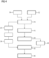
- Fig.4
- shows a flow diagram illustrating a setting of a target value according to a preferred embodiment.
- Fig.5
- shows a flow diagram illustrating a method for adjusting a centre frequency of a magnetic resonance tomography device according to a fourth preferred embodiment of the present invention.
- In
figure 1 a flow diagram illustrating a method for adjusting a centre frequency of a magnetic resonance tomography (MRT)-device 1 according to a first preferred embodiment of the present invention is shown. Essential element of a magnetic MRT-device 1 are a magnetic field generated by amagnet 2 and a high frequency pulse. For recording a MRT-imaging energy from an oscillating magnetic field temporarily is applied to a patient or a probe, such as a phantom, at an appropriate centre frequency. As a consequence, excited hydrogen atoms emit a radio frequency signal, which is measured by a receiving coil. Preferably, a high frequency amplifier is provided for covering a frequency band surrounding the centre frequency for takin into account a frequency shift caused by a thickness of the probe, in particular the patient, being measured. However, a transmission performance strongly depends on deviation of the emitted frequency from the desired centre frequency being optimized for the receiving coil, in particular in the case of magnetic fields being smaller than 1 T or 0.5 T, due to reflection effects. These reflection effects are in particular result of a reduced conductivity of tissue, preferably human tissue, for low centre frequencies that are assigned to small magnetic fields. As a result, at the receiving coil losses caused by the patient are smaller and the reflection factor changes more strongly compared to system using higher magnetic fields. Another problem is the different reflection factors being respectively assigned to parts of the receiving coil, and resulting in a reduced transmission performance. - Thus, a mismatch between the centre frequency caused by the magnetic field and the centre frequency of the receiving coil should be avoided. However, the magnetic field determining the centre frequency decreases over time or is adjusted inaccurately by an automatic ramp-up
mode 20 transferring the magnet from a non-operating state in an operating state. Such an automatic ramp-upmode 20 follows a ramp-down mode being preferably needed for "dry magnets" having a high probability for shutting down due to a malfunction of a cooling and/or due to a power failure. According to the embodiment shown infigure 1 it is provided that the magnet field is re-established after a ramp-down mode 10 in the ramp-upmode 20 transferring the magnet from the non-operating state to the operating state. Preferably, a functionality of the MRT-device such as a cooling mechanism or a current supply is recovered in the time between finishing the ramp-down mode 10 and starting the ramp-upmode 20. For adjusting the proper magnetic field corresponding to the desired centre frequency being optimized for the receiving coil observing 30 a reference parameter is provided, in particular measured. Such a reference parameter might be a current or a frequency. Furthermore, setting 25 a target value for the reference parameter is provided. By comparing the observed reference parameter to the target value, it is possible to finish the ramp-upmode 20, when the reference parameters corresponds to the target value. As a consequence, it is possible to control the magnetic field by using the reference parameter instead of measuring the magnetic field directly. Thus adjusting the magnetic field can be done without expansive devices for measuring the magnetic field. - In
figure 2 a flow diagram illustrating a method for adjusting a centre frequency of a magnetic resonance tomography device according to a second preferred embodiment of the present invention is shown. In the embodiment presented infigure 2 , it is provided that the reference parameter is a frequency, preferably the frequency emitted by a phantom being exposed to the magnetic field and the high frequency pulse during the ramp-upmode 20. By comparing 35 the emitted frequency and the target value, i. e. the center frequency assigned to the receiving coil, it is possible to finish the ramp-up, when the measured frequency reaches the center frequency. Then the desired magnet filed is established, in particular re-established. For measuring the frequency of the radiation emitted by the phantom it is provided that the phantom is placed into the MRT-device 1, in particular inside the magnet, before the ramp-upmode 20 is started or the ramp-down mode is finished. It is also conceivable that the phantom, for example a PTAB phantom, is placed automatically at the proper spot for the rump-upmode 20 that is intended to adjust the desired magnet field. It is also conceivable that the rump-upmode 20 starts and the observing 30 of the reference value starts when an approximated magnetic field below the target magnetic field is reached. Subsequently the phantom is placed and the ramp-upmode 20 is continued, in particular by incrementally increasing the magnetic field, until the phantom emits the center frequency. Thus, a part of the ramp-upmode 20 can be performed without a phantom, for example during the night. - In the embodiment presented in
figure 3 it is provided that the reference parameter is a current, in particular the current used for establishing the desired magnet field. Preferably, the current is measured by ashunt 62 integrated to amagnetic power supply 60 providing the current for realizing the desired magnetic field. In this scenario, the target value corresponds to the current establishing the desired magnetic field and the ramp-upmode 20 is finished as soon as the target value, in particular the target current, is reached. - Preferably, the method comprises setting 24 the target value, for example by a calibration process. In
figure 4 setting 25 the target value by a calibration process or calibration mode during a ramp-upmode 20 or a ramp-down mode 10 is shown. For example, the setting 25 of the target value by the calibration process is performed during the installation of the MRT device or the target value is refreshed by repeating the calibration process after a determined set of time, for example each six month. For calibrating it is provided that in a calibration mode the frequency is observed. As soon as the frequency reaches the desired center frequency the current is measured and saved to a memory device. The saved current value represents the set target value. By refreshing the target value it is advantageously possible to take into account that the current measuring device ages. Thus, the center frequency is maintained at its optimum level. - In
figure 4 a block diagram is shown illustrating a method for adjusting the magnetic field in a MRT-device 1 according to a fourth preferred embodiment. Similar to the embodiment offigure 4 the reference parameter is the current, in particular the current in ashunt 62 integrated to themagnetic power supply 62. In contrast to the embodiment offigure 4 the target value is set during an emergency ramp-down mode. In particular, the current is measured in the initial phase of the ramp-down-mode 10, preferably before the current is decreased for shutting down the MRT-device. As a result, it is possible to re-establish the magnet field by using the last known current value that established the proper magnetic field before the emergency ramp down mode. Thus, in a simple and efficient way the magnetic field is reset accurately and complex procedures involving regular service visits or customer involvements, such as placing the phantom into the MRT-device, are avoided. - In
figure 5 a circuit diagram for a MRT-device is schematically shown. In particular, it is provided that the current for the magnet of the MRT device is provided by amagnetic power supply 60. Further, the circuit diagram comprisesdiodes 61 being connected in parallel. For measuring the current used for establishing the magnet field of the magnet ashunt 62 is provided. The shunt is preferably integrated between thediodes 61 and themagnet 2. The observed current is transferred to acontrol unit 65. Thecontrol unit 65 preferably compares the observed current to the target value saved in the memory and stops the ramp-upmode 20 of the magnetic power supply as soon as the target value is reached by the reference parameter.
Claims (15)
- Method for adjusting a magnetic field of a magnetic resonance tomography (MRT)-device (1) having a magnet (2), comprising:- transferring the magnet (2) from an operating state to a non-operating state in a ramp-down mode (10);- subsequently transferring the magnet (2) from the non-operating state to the operating state in a ramp-up mode (20) ;- observing (20) a reference parameter different from the magnetic field;- setting (25) a target value for the reference parameter;- comparing (35) the observed reference parameter to the target value; and- finishing (40) the ramp-up mode when the reference parameter reaches the target value.
- Method according to claim 1, wherein the reference parameter is a current, in particular the current for realizing the magnetic field of the magnet.
- Method according to claim 2, wherein for setting (25) the target value the current is calibrated during a previous ramp-up mode (20), for example the preceding ramp-up mode (20) .
- Method according to claim 2 or claim 3, wherein for setting (25) the target value the current is calibrated during a previous ramp down mode (10), in particular during the ramp-down mode (10) preceding the ramp-up mode (20).
- Method according to claim 4, wherein for setting (25) the target value the current is observed during an initiation phase of the ramp-down mode (10).
- Method according to one of the claims 2 to 5, wherein the current is measured by a current measuring device included into a magnetic power supply (60) of the MRT-device (1).
- Method according to one of the claims 4 to 6, wherein the ramp-down mode (10) is an emergency ramp-down mode.
- Method according to claim 1, wherein the reference parameter is a frequency, in particular a frequency emitted by a phantom being placed into the MRT-device (1).
- Method according to claim 8, wherein the phantom is placed, preferably automatically placed, into the MRT-device (1) before the ramp-up mode (20) starts or during the ramp-up mode (20).
- Method according to one of the preceding claims, wherein the target value is reset after a predefined period of time, in particular automatically.
- Method according to one of the preceding claims, wherein the ramp-down mode (10) is initiated by a control unit (65)- by a failure message (51) of the MRT-device- after a defined time sequence and/or- as a result of a activation (52).
- Method according to one of the preceding claims, wherein a magnetic field in the operating state is smaller than 1.5 T, preferably smaller than 1.0 T and more preferably smaller than 0.5 T.
- Magnetic power supply (60) being configured for- transferring the magnet (2) from an operating state to a non-operating state in a ramp down mode (10);- subsequently transferring the magnet (2) from the non-operating state to the operating state in a ramp-up mode (20)- observing (30) a reference parameter- setting (25) a target value for the reference parameter;- comparing (35) the observed reference parameter to the target value; and- finishing (40) the ramp-up mode when the reference parameter reaches a target value.
- Magnetic power supply (62) according to claim 12, wherein the magnetic power supply (62) includes a current measuring device.
- Magnetic resonance tomography (MRT)-device (1) being configured for- transferring the magnet from an operating state to a non-operating state in a ramp-down mode (10);- subsequently transferring the magnet from the non-operating state to the operating state in a ramp-up mode (20)- observing (30) a reference parameter; and- setting (25) a target value for the reference parameter;- comparing (35) the observed reference parameter to the target value; and- finishing (40) the ramp-up mode (20) when the reference parameter reaches a target value.
Priority Applications (3)
| Application Number | Priority Date | Filing Date | Title |
|---|---|---|---|
| EP17195210.4A EP3467532B1 (en) | 2017-10-06 | 2017-10-06 | Method for adjusting a magnetic field of a magnetic resonance tomography (mrt) device |
| CN201811143958.0A CN109633501B (en) | 2017-10-06 | 2018-09-28 | Method for adjusting a magnetic field of a Magnetic Resonance Tomography (MRT) device |
| US16/149,248 US10698051B2 (en) | 2017-10-06 | 2018-10-02 | Methods for adjusting a magnetic field of a magnetic resonance tomography device, magnetic power supplies, and magnetic resonance tomography devices |
Applications Claiming Priority (1)
| Application Number | Priority Date | Filing Date | Title |
|---|---|---|---|
| EP17195210.4A EP3467532B1 (en) | 2017-10-06 | 2017-10-06 | Method for adjusting a magnetic field of a magnetic resonance tomography (mrt) device |
Publications (2)
| Publication Number | Publication Date |
|---|---|
| EP3467532A1 true EP3467532A1 (en) | 2019-04-10 |
| EP3467532B1 EP3467532B1 (en) | 2021-10-06 |
Family
ID=60037475
Family Applications (1)
| Application Number | Title | Priority Date | Filing Date |
|---|---|---|---|
| EP17195210.4A Active EP3467532B1 (en) | 2017-10-06 | 2017-10-06 | Method for adjusting a magnetic field of a magnetic resonance tomography (mrt) device |
Country Status (3)
| Country | Link |
|---|---|
| US (1) | US10698051B2 (en) |
| EP (1) | EP3467532B1 (en) |
| CN (1) | CN109633501B (en) |
Cited By (1)
| Publication number | Priority date | Publication date | Assignee | Title |
|---|---|---|---|---|
| EP3739353A1 (en) * | 2019-05-15 | 2020-11-18 | Siemens Healthcare GmbH | Method and device for controlling a magnetic resonance imaging system |
Families Citing this family (2)
| Publication number | Priority date | Publication date | Assignee | Title |
|---|---|---|---|---|
| EP3457154B1 (en) * | 2017-09-13 | 2020-04-08 | Melexis Technologies SA | Stray field rejection in magnetic sensors |
| US11193997B2 (en) * | 2018-08-21 | 2021-12-07 | Siemens Healthcare Gmbh | Operating an MRI apparatus |
Citations (3)
| Publication number | Priority date | Publication date | Assignee | Title |
|---|---|---|---|---|
| US20050111159A1 (en) * | 2003-11-26 | 2005-05-26 | Knight Larry K. | Automated superconducting magnet ramp-up system and method |
| WO2014199793A1 (en) * | 2013-06-13 | 2014-12-18 | 株式会社 日立メディコ | Magnetic resonance imaging device and method for operating same |
| WO2016106037A1 (en) * | 2014-12-24 | 2016-06-30 | General Electric Company | Control system and method for a superconducting magnet |
Family Cites Families (10)
| Publication number | Priority date | Publication date | Assignee | Title |
|---|---|---|---|---|
| US6150912A (en) * | 1999-11-15 | 2000-11-21 | General Electric Company | Open architecture superconducting magnet helium vessel structure |
| US6397850B1 (en) * | 2000-02-09 | 2002-06-04 | Scimed Life Systems Inc | Dual-mode apparatus and method for detection of embolic device detachment |
| US6335670B1 (en) * | 2000-04-14 | 2002-01-01 | Marconi Medical Systems Finland, Inc. | Mri system with split rose ring with high homogeneity |
| GB2426630B (en) * | 2005-05-26 | 2007-11-21 | Siemens Magnet Technology Ltd | Electromagnet |
| JP4399610B2 (en) * | 2006-09-26 | 2010-01-20 | 国立大学法人九州工業大学 | Magnetic property measuring method and system |
| US8729894B2 (en) * | 2010-07-30 | 2014-05-20 | General Electric Company | System and method for operating a magnetic resonance imaging system during ramping |
| KR101362772B1 (en) * | 2012-02-06 | 2014-02-13 | 삼성전자주식회사 | Cryocooler and superconducting magnet apparatus employing the same |
| BR112015006485A2 (en) * | 2012-09-27 | 2017-07-04 | Koninklijke Philips Nv | apparatus, method for operating an electromagnet system and electromagnet system |
| CN103869268B (en) * | 2012-12-18 | 2017-07-04 | 上海联影医疗科技有限公司 | Coil testing device, magnetic resonance system and output correction method and device thereof |
| US10060995B2 (en) * | 2015-10-16 | 2018-08-28 | Synaptive Medical (Barbados) Inc. | Magnetic resonance imaging system capable of rapid field ramping |
-
2017
- 2017-10-06 EP EP17195210.4A patent/EP3467532B1/en active Active
-
2018
- 2018-09-28 CN CN201811143958.0A patent/CN109633501B/en active Active
- 2018-10-02 US US16/149,248 patent/US10698051B2/en active Active
Patent Citations (3)
| Publication number | Priority date | Publication date | Assignee | Title |
|---|---|---|---|---|
| US20050111159A1 (en) * | 2003-11-26 | 2005-05-26 | Knight Larry K. | Automated superconducting magnet ramp-up system and method |
| WO2014199793A1 (en) * | 2013-06-13 | 2014-12-18 | 株式会社 日立メディコ | Magnetic resonance imaging device and method for operating same |
| WO2016106037A1 (en) * | 2014-12-24 | 2016-06-30 | General Electric Company | Control system and method for a superconducting magnet |
Cited By (2)
| Publication number | Priority date | Publication date | Assignee | Title |
|---|---|---|---|---|
| EP3739353A1 (en) * | 2019-05-15 | 2020-11-18 | Siemens Healthcare GmbH | Method and device for controlling a magnetic resonance imaging system |
| US11137469B2 (en) | 2019-05-15 | 2021-10-05 | Siemens Healthcare Gmbh | Method and device for controlling a magnetic resonance imaging system |
Also Published As
| Publication number | Publication date |
|---|---|
| CN109633501B (en) | 2022-01-14 |
| US10698051B2 (en) | 2020-06-30 |
| US20190107591A1 (en) | 2019-04-11 |
| EP3467532B1 (en) | 2021-10-06 |
| CN109633501A (en) | 2019-04-16 |
Similar Documents
| Publication | Publication Date | Title |
|---|---|---|
| US10698051B2 (en) | Methods for adjusting a magnetic field of a magnetic resonance tomography device, magnetic power supplies, and magnetic resonance tomography devices | |
| CN103027679B (en) | For controlling the method for magnetic resonance system | |
| WO2014199793A1 (en) | Magnetic resonance imaging device and method for operating same | |
| EP2568307A1 (en) | Improved patient positioning within an MRI device | |
| US12105168B2 (en) | Operating an MRI apparatus | |
| US20190072624A1 (en) | Method and magnetic resonance apparatus for monitoring a cooling system of the magnetic resonance apparatus | |
| JP7844595B2 (en) | Magnetic resonance imaging apparatus and control method | |
| US20230384405A1 (en) | Magnetic resonance imaging system, magnetic resonance imaging apparatus, cooling control device, and cooling control method | |
| CN111948588B (en) | Method and apparatus for controlling a magnetic resonance imaging system | |
| US20150097566A1 (en) | Method and device for controlling a magnetic resonance imaging apparatus | |
| US12248046B2 (en) | Operating a magnetic resonance device | |
| WO2013038960A1 (en) | Mri device, operation method thereof, quenching prevention device | |
| CN109814057B (en) | Method for operating a magnetic resonance imaging device and magnetic resonance imaging device | |
| EP3614163B1 (en) | Method of operating an mri apparatus | |
| CN112955766B (en) | MRI system and method for generating RF pulses for an MRI system | |
| EP3614160B1 (en) | Method of ramping a magnet of a magnetic resonance imaging apparatus based on a measured centre frequency of the body coil | |
| JP6571456B2 (en) | Magnetic resonance imaging system | |
| US12553971B2 (en) | Method for optimizing a protocol for operating a magnetic resonance device | |
| US20250060439A1 (en) | Mri system | |
| CN110850346B (en) | Method of operating an MRI apparatus | |
| JP2015020027A (en) | Superconducting coil drive system and imaging device | |
| JP2007325876A (en) | Nuclear magnetic resonance imaging apparatus | |
| JPWO2015072301A1 (en) | Magnetic resonance imaging system |
Legal Events
| Date | Code | Title | Description |
|---|---|---|---|
| PUAI | Public reference made under article 153(3) epc to a published international application that has entered the european phase |
Free format text: ORIGINAL CODE: 0009012 |
|
| STAA | Information on the status of an ep patent application or granted ep patent |
Free format text: STATUS: THE APPLICATION HAS BEEN PUBLISHED |
|
| AK | Designated contracting states |
Kind code of ref document: A1 Designated state(s): AL AT BE BG CH CY CZ DE DK EE ES FI FR GB GR HR HU IE IS IT LI LT LU LV MC MK MT NL NO PL PT RO RS SE SI SK SM TR |
|
| AX | Request for extension of the european patent |
Extension state: BA ME |
|
| STAA | Information on the status of an ep patent application or granted ep patent |
Free format text: STATUS: REQUEST FOR EXAMINATION WAS MADE |
|
| 17P | Request for examination filed |
Effective date: 20190503 |
|
| RBV | Designated contracting states (corrected) |
Designated state(s): AL AT BE BG CH CY CZ DE DK EE ES FI FR GB GR HR HU IE IS IT LI LT LU LV MC MK MT NL NO PL PT RO RS SE SI SK SM TR |
|
| STAA | Information on the status of an ep patent application or granted ep patent |
Free format text: STATUS: EXAMINATION IS IN PROGRESS |
|
| 17Q | First examination report despatched |
Effective date: 20201030 |
|
| GRAP | Despatch of communication of intention to grant a patent |
Free format text: ORIGINAL CODE: EPIDOSNIGR1 |
|
| STAA | Information on the status of an ep patent application or granted ep patent |
Free format text: STATUS: GRANT OF PATENT IS INTENDED |
|
| INTG | Intention to grant announced |
Effective date: 20210607 |
|
| RIN1 | Information on inventor provided before grant (corrected) |
Inventor name: ALEY, NICHOLAS Inventor name: BIBER, STEPHAN |
|
| GRAS | Grant fee paid |
Free format text: ORIGINAL CODE: EPIDOSNIGR3 |
|
| GRAA | (expected) grant |
Free format text: ORIGINAL CODE: 0009210 |
|
| STAA | Information on the status of an ep patent application or granted ep patent |
Free format text: STATUS: THE PATENT HAS BEEN GRANTED |
|
| AK | Designated contracting states |
Kind code of ref document: B1 Designated state(s): AL AT BE BG CH CY CZ DE DK EE ES FI FR GB GR HR HU IE IS IT LI LT LU LV MC MK MT NL NO PL PT RO RS SE SI SK SM TR |
|
| REG | Reference to a national code |
Ref country code: GB Ref legal event code: FG4D |
|
| REG | Reference to a national code |
Ref country code: CH Ref legal event code: EP Ref country code: AT Ref legal event code: REF Ref document number: 1436671 Country of ref document: AT Kind code of ref document: T Effective date: 20211015 |
|
| REG | Reference to a national code |
Ref country code: DE Ref legal event code: R096 Ref document number: 602017047071 Country of ref document: DE |
|
| REG | Reference to a national code |
Ref country code: IE Ref legal event code: FG4D |
|
| REG | Reference to a national code |
Ref country code: LT Ref legal event code: MG9D |
|
| REG | Reference to a national code |
Ref country code: NL Ref legal event code: MP Effective date: 20211006 |
|
| REG | Reference to a national code |
Ref country code: AT Ref legal event code: MK05 Ref document number: 1436671 Country of ref document: AT Kind code of ref document: T Effective date: 20211006 |
|
| PG25 | Lapsed in a contracting state [announced via postgrant information from national office to epo] |
Ref country code: RS Free format text: LAPSE BECAUSE OF FAILURE TO SUBMIT A TRANSLATION OF THE DESCRIPTION OR TO PAY THE FEE WITHIN THE PRESCRIBED TIME-LIMIT Effective date: 20211006 Ref country code: LT Free format text: LAPSE BECAUSE OF FAILURE TO SUBMIT A TRANSLATION OF THE DESCRIPTION OR TO PAY THE FEE WITHIN THE PRESCRIBED TIME-LIMIT Effective date: 20211006 Ref country code: FI Free format text: LAPSE BECAUSE OF FAILURE TO SUBMIT A TRANSLATION OF THE DESCRIPTION OR TO PAY THE FEE WITHIN THE PRESCRIBED TIME-LIMIT Effective date: 20211006 Ref country code: BG Free format text: LAPSE BECAUSE OF FAILURE TO SUBMIT A TRANSLATION OF THE DESCRIPTION OR TO PAY THE FEE WITHIN THE PRESCRIBED TIME-LIMIT Effective date: 20220106 Ref country code: AT Free format text: LAPSE BECAUSE OF FAILURE TO SUBMIT A TRANSLATION OF THE DESCRIPTION OR TO PAY THE FEE WITHIN THE PRESCRIBED TIME-LIMIT Effective date: 20211006 |
|
| REG | Reference to a national code |
Ref country code: CH Ref legal event code: PL |
|
| PG25 | Lapsed in a contracting state [announced via postgrant information from national office to epo] |
Ref country code: IS Free format text: LAPSE BECAUSE OF FAILURE TO SUBMIT A TRANSLATION OF THE DESCRIPTION OR TO PAY THE FEE WITHIN THE PRESCRIBED TIME-LIMIT Effective date: 20220206 Ref country code: SE Free format text: LAPSE BECAUSE OF FAILURE TO SUBMIT A TRANSLATION OF THE DESCRIPTION OR TO PAY THE FEE WITHIN THE PRESCRIBED TIME-LIMIT Effective date: 20211006 Ref country code: PT Free format text: LAPSE BECAUSE OF FAILURE TO SUBMIT A TRANSLATION OF THE DESCRIPTION OR TO PAY THE FEE WITHIN THE PRESCRIBED TIME-LIMIT Effective date: 20220207 Ref country code: PL Free format text: LAPSE BECAUSE OF FAILURE TO SUBMIT A TRANSLATION OF THE DESCRIPTION OR TO PAY THE FEE WITHIN THE PRESCRIBED TIME-LIMIT Effective date: 20211006 Ref country code: NO Free format text: LAPSE BECAUSE OF FAILURE TO SUBMIT A TRANSLATION OF THE DESCRIPTION OR TO PAY THE FEE WITHIN THE PRESCRIBED TIME-LIMIT Effective date: 20220106 Ref country code: NL Free format text: LAPSE BECAUSE OF FAILURE TO SUBMIT A TRANSLATION OF THE DESCRIPTION OR TO PAY THE FEE WITHIN THE PRESCRIBED TIME-LIMIT Effective date: 20211006 Ref country code: LV Free format text: LAPSE BECAUSE OF FAILURE TO SUBMIT A TRANSLATION OF THE DESCRIPTION OR TO PAY THE FEE WITHIN THE PRESCRIBED TIME-LIMIT Effective date: 20211006 Ref country code: HR Free format text: LAPSE BECAUSE OF FAILURE TO SUBMIT A TRANSLATION OF THE DESCRIPTION OR TO PAY THE FEE WITHIN THE PRESCRIBED TIME-LIMIT Effective date: 20211006 Ref country code: GR Free format text: LAPSE BECAUSE OF FAILURE TO SUBMIT A TRANSLATION OF THE DESCRIPTION OR TO PAY THE FEE WITHIN THE PRESCRIBED TIME-LIMIT Effective date: 20220107 Ref country code: ES Free format text: LAPSE BECAUSE OF FAILURE TO SUBMIT A TRANSLATION OF THE DESCRIPTION OR TO PAY THE FEE WITHIN THE PRESCRIBED TIME-LIMIT Effective date: 20211006 |
|
| REG | Reference to a national code |
Ref country code: BE Ref legal event code: MM Effective date: 20211031 |
|
| REG | Reference to a national code |
Ref country code: DE Ref legal event code: R097 Ref document number: 602017047071 Country of ref document: DE |
|
| PG25 | Lapsed in a contracting state [announced via postgrant information from national office to epo] |
Ref country code: SM Free format text: LAPSE BECAUSE OF FAILURE TO SUBMIT A TRANSLATION OF THE DESCRIPTION OR TO PAY THE FEE WITHIN THE PRESCRIBED TIME-LIMIT Effective date: 20211006 Ref country code: SK Free format text: LAPSE BECAUSE OF FAILURE TO SUBMIT A TRANSLATION OF THE DESCRIPTION OR TO PAY THE FEE WITHIN THE PRESCRIBED TIME-LIMIT Effective date: 20211006 Ref country code: RO Free format text: LAPSE BECAUSE OF FAILURE TO SUBMIT A TRANSLATION OF THE DESCRIPTION OR TO PAY THE FEE WITHIN THE PRESCRIBED TIME-LIMIT Effective date: 20211006 Ref country code: MC Free format text: LAPSE BECAUSE OF FAILURE TO SUBMIT A TRANSLATION OF THE DESCRIPTION OR TO PAY THE FEE WITHIN THE PRESCRIBED TIME-LIMIT Effective date: 20211006 Ref country code: LU Free format text: LAPSE BECAUSE OF NON-PAYMENT OF DUE FEES Effective date: 20211006 Ref country code: EE Free format text: LAPSE BECAUSE OF FAILURE TO SUBMIT A TRANSLATION OF THE DESCRIPTION OR TO PAY THE FEE WITHIN THE PRESCRIBED TIME-LIMIT Effective date: 20211006 Ref country code: DK Free format text: LAPSE BECAUSE OF FAILURE TO SUBMIT A TRANSLATION OF THE DESCRIPTION OR TO PAY THE FEE WITHIN THE PRESCRIBED TIME-LIMIT Effective date: 20211006 Ref country code: CZ Free format text: LAPSE BECAUSE OF FAILURE TO SUBMIT A TRANSLATION OF THE DESCRIPTION OR TO PAY THE FEE WITHIN THE PRESCRIBED TIME-LIMIT Effective date: 20211006 Ref country code: BE Free format text: LAPSE BECAUSE OF NON-PAYMENT OF DUE FEES Effective date: 20211031 |
|
| PLBE | No opposition filed within time limit |
Free format text: ORIGINAL CODE: 0009261 |
|
| STAA | Information on the status of an ep patent application or granted ep patent |
Free format text: STATUS: NO OPPOSITION FILED WITHIN TIME LIMIT |
|
| PG25 | Lapsed in a contracting state [announced via postgrant information from national office to epo] |
Ref country code: LI Free format text: LAPSE BECAUSE OF NON-PAYMENT OF DUE FEES Effective date: 20211031 Ref country code: CH Free format text: LAPSE BECAUSE OF NON-PAYMENT OF DUE FEES Effective date: 20211031 |
|
| 26N | No opposition filed |
Effective date: 20220707 |
|
| PG25 | Lapsed in a contracting state [announced via postgrant information from national office to epo] |
Ref country code: IE Free format text: LAPSE BECAUSE OF NON-PAYMENT OF DUE FEES Effective date: 20211006 Ref country code: AL Free format text: LAPSE BECAUSE OF FAILURE TO SUBMIT A TRANSLATION OF THE DESCRIPTION OR TO PAY THE FEE WITHIN THE PRESCRIBED TIME-LIMIT Effective date: 20211006 |
|
| PG25 | Lapsed in a contracting state [announced via postgrant information from national office to epo] |
Ref country code: SI Free format text: LAPSE BECAUSE OF FAILURE TO SUBMIT A TRANSLATION OF THE DESCRIPTION OR TO PAY THE FEE WITHIN THE PRESCRIBED TIME-LIMIT Effective date: 20211006 |
|
| PG25 | Lapsed in a contracting state [announced via postgrant information from national office to epo] |
Ref country code: IT Free format text: LAPSE BECAUSE OF FAILURE TO SUBMIT A TRANSLATION OF THE DESCRIPTION OR TO PAY THE FEE WITHIN THE PRESCRIBED TIME-LIMIT Effective date: 20211006 |
|
| PG25 | Lapsed in a contracting state [announced via postgrant information from national office to epo] |
Ref country code: CY Free format text: LAPSE BECAUSE OF FAILURE TO SUBMIT A TRANSLATION OF THE DESCRIPTION OR TO PAY THE FEE WITHIN THE PRESCRIBED TIME-LIMIT Effective date: 20211006 |
|
| PG25 | Lapsed in a contracting state [announced via postgrant information from national office to epo] |
Ref country code: HU Free format text: LAPSE BECAUSE OF FAILURE TO SUBMIT A TRANSLATION OF THE DESCRIPTION OR TO PAY THE FEE WITHIN THE PRESCRIBED TIME-LIMIT; INVALID AB INITIO Effective date: 20171006 |
|
| REG | Reference to a national code |
Ref country code: DE Ref legal event code: R081 Ref document number: 602017047071 Country of ref document: DE Owner name: SIEMENS HEALTHINEERS AG, DE Free format text: FORMER OWNER: SIEMENS HEALTHCARE GMBH, MUENCHEN, DE |
|
| PG25 | Lapsed in a contracting state [announced via postgrant information from national office to epo] |
Ref country code: MK Free format text: LAPSE BECAUSE OF FAILURE TO SUBMIT A TRANSLATION OF THE DESCRIPTION OR TO PAY THE FEE WITHIN THE PRESCRIBED TIME-LIMIT Effective date: 20211006 |
|
| PG25 | Lapsed in a contracting state [announced via postgrant information from national office to epo] |
Ref country code: MT Free format text: LAPSE BECAUSE OF FAILURE TO SUBMIT A TRANSLATION OF THE DESCRIPTION OR TO PAY THE FEE WITHIN THE PRESCRIBED TIME-LIMIT Effective date: 20211006 |
|
| PG25 | Lapsed in a contracting state [announced via postgrant information from national office to epo] |
Ref country code: TR Free format text: LAPSE BECAUSE OF FAILURE TO SUBMIT A TRANSLATION OF THE DESCRIPTION OR TO PAY THE FEE WITHIN THE PRESCRIBED TIME-LIMIT Effective date: 20211006 |
|
| PGFP | Annual fee paid to national office [announced via postgrant information from national office to epo] |
Ref country code: GB Payment date: 20251111 Year of fee payment: 9 |
|
| PGFP | Annual fee paid to national office [announced via postgrant information from national office to epo] |
Ref country code: FR Payment date: 20251020 Year of fee payment: 9 |
|
| PGFP | Annual fee paid to national office [announced via postgrant information from national office to epo] |
Ref country code: DE Payment date: 20251219 Year of fee payment: 9 |