EP3467479A1 - Reflection characteristic measuring device - Google Patents
Reflection characteristic measuring device Download PDFInfo
- Publication number
- EP3467479A1 EP3467479A1 EP17806494.5A EP17806494A EP3467479A1 EP 3467479 A1 EP3467479 A1 EP 3467479A1 EP 17806494 A EP17806494 A EP 17806494A EP 3467479 A1 EP3467479 A1 EP 3467479A1
- Authority
- EP
- European Patent Office
- Prior art keywords
- measurement
- measurer
- reflection characteristic
- light
- correction
- Prior art date
- Legal status (The legal status is an assumption and is not a legal conclusion. Google has not performed a legal analysis and makes no representation as to the accuracy of the status listed.)
- Granted
Links
Images


Classifications
-
- G—PHYSICS
- G01—MEASURING; TESTING
- G01J—MEASUREMENT OF INTENSITY, VELOCITY, SPECTRAL CONTENT, POLARISATION, PHASE OR PULSE CHARACTERISTICS OF INFRARED, VISIBLE OR ULTRAVIOLET LIGHT; COLORIMETRY; RADIATION PYROMETRY
- G01J3/00—Spectrometry; Spectrophotometry; Monochromators; Measuring colours
- G01J3/46—Measurement of colour; Colour measuring devices, e.g. colorimeters
- G01J3/50—Measurement of colour; Colour measuring devices, e.g. colorimeters using electric radiation detectors
-
- G—PHYSICS
- G01—MEASURING; TESTING
- G01N—INVESTIGATING OR ANALYSING MATERIALS BY DETERMINING THEIR CHEMICAL OR PHYSICAL PROPERTIES
- G01N21/00—Investigating or analysing materials by the use of optical means, i.e. using sub-millimetre waves, infrared, visible or ultraviolet light
- G01N21/17—Systems in which incident light is modified in accordance with the properties of the material investigated
- G01N21/25—Colour; Spectral properties, i.e. comparison of effect of material on the light at two or more different wavelengths or wavelength bands
- G01N21/251—Colorimeters; Construction thereof
-
- G—PHYSICS
- G01—MEASURING; TESTING
- G01N—INVESTIGATING OR ANALYSING MATERIALS BY DETERMINING THEIR CHEMICAL OR PHYSICAL PROPERTIES
- G01N21/00—Investigating or analysing materials by the use of optical means, i.e. using sub-millimetre waves, infrared, visible or ultraviolet light
- G01N21/17—Systems in which incident light is modified in accordance with the properties of the material investigated
- G01N21/25—Colour; Spectral properties, i.e. comparison of effect of material on the light at two or more different wavelengths or wavelength bands
- G01N21/255—Details, e.g. use of specially adapted sources, lighting or optical systems
-
- G—PHYSICS
- G01—MEASURING; TESTING
- G01N—INVESTIGATING OR ANALYSING MATERIALS BY DETERMINING THEIR CHEMICAL OR PHYSICAL PROPERTIES
- G01N21/00—Investigating or analysing materials by the use of optical means, i.e. using sub-millimetre waves, infrared, visible or ultraviolet light
- G01N21/17—Systems in which incident light is modified in accordance with the properties of the material investigated
- G01N21/25—Colour; Spectral properties, i.e. comparison of effect of material on the light at two or more different wavelengths or wavelength bands
- G01N21/27—Colour; Spectral properties, i.e. comparison of effect of material on the light at two or more different wavelengths or wavelength bands using photo-electric detection ; circuits for computing concentration
-
- G—PHYSICS
- G01—MEASURING; TESTING
- G01N—INVESTIGATING OR ANALYSING MATERIALS BY DETERMINING THEIR CHEMICAL OR PHYSICAL PROPERTIES
- G01N21/00—Investigating or analysing materials by the use of optical means, i.e. using sub-millimetre waves, infrared, visible or ultraviolet light
- G01N21/17—Systems in which incident light is modified in accordance with the properties of the material investigated
- G01N21/55—Specular reflectivity
- G01N21/57—Measuring gloss
-
- G—PHYSICS
- G01—MEASURING; TESTING
- G01N—INVESTIGATING OR ANALYSING MATERIALS BY DETERMINING THEIR CHEMICAL OR PHYSICAL PROPERTIES
- G01N2201/00—Features of devices classified in G01N21/00
- G01N2201/06—Illumination; Optics
- G01N2201/065—Integrating spheres
Definitions
- the present invention relates to a reflection characteristic measuring device that illuminates an object of measurement, which is an object to be measured, and measures its reflection characteristic.
- a reflection characteristic measuring device that measures a reflection characteristic.
- the reflection characteristic include, for example, a spectral reflectance, a gloss value, brilliance, and the like.
- the spectral reflectance is a reflectance for each wavelength.
- the gloss value is a numerical value that represents a degree of glossiness, and is obtained according to a ratio between intensity of specular reflection light and intensity of scattered reflection light.
- the brilliance is a numerical value representing a glittering appearance caused by a brightening agent (such as aluminum flake) included in a metallic paint, a pearl paint, and the like.
- Those various reflection characteristics are defined by, for example, standards and the like, and there is geometry suitable for the measurement.
- the spectral reflectance is measured using geometry such as 45° illumination / 0° reception, 45° illumination / multi-angle reception, and diffuse illumination / 8° reception.
- the gloss value is measured using geometry of 20° gloss (20° illumination / 20° reception), 60° gloss (60° illumination / 60° reception), and 85° gloss (85° illumination / 85° reception). Therefore, conventionally, in general, the spectral reflectance has been measured by, for example, a spectroscope for spectral reflectance measurement, the gloss value has been measured by, for example, a glossmeter for gloss measurement, and the brilliance has been measured by a measuring device for brilliance measurement.
- Patent Literature 1 those plurality of measuring devices is integrated into one measuring device, and a device capable of measuring a plurality of types of reflection characteristics with respect to the same part of an object of measurement, which is an object to be measured, has been developed.
- the integrated measuring device includes a plurality of geometries to make it possible to measure a plurality of types of reflection characteristics.
- the integrated measuring device is provided with a geometry including the diffuse reflecting member (first geometry) as necessary for the measurement, and a geometry not including the diffuse reflecting member (second geometry) unnecessary for the measurement.
- the light in the second geometry is diffusely reflected by the diffuse reflecting surface of the first geometry, and the diffusely reflected light and the light caused by the diffused light may be measured using the second geometry at times, which results in a measurement error.
- the geometry of diffuse illumination/8° reception and the geometry of 60° gloss are integrated, while the illumination light in the geometry of 60° gloss is reflected by a surface of the object to be measured and most of the reflected light is received and measured by a light receiving part in the geometry of 60° gloss, a part of the reflected light is made incident on the integrating sphere in the geometry of diffuse illumination/8° reception.
- the reflected light is roughly divided into surface reflected light having been subject to Fresnel reflection on the surface and internal diffuse reflected light that once penetrates into the object to be measured, being absorbed by the object to be measured, for example, and then being emitted from the surface.
- the surface reflected light is scattered due to surface roughness of the object to be measured, and light having an angle larger than an acceptance angle range at the geometry of 60° gloss is made incident on the integrating sphere.
- Most of the internal diffuse reflected light is made incident on the integrating sphere.
- the light having been incident on the integrating sphere repeats irregular reflection in the integrating sphere, and a part of the light illuminates the object to be measured (recursive diffused illumination).
- the light based on the recursive diffused illumination acts on the object to be measured in a similar manner to the illumination light in the geometry of 60° gloss described above. As a result, a part of the light is received by the light receiving part in the geometry of 60° gloss, which results in a measurement error.
- Patent Literature 1 US 7741629 B2
- the present invention has been conceived in view of the circumstances described above, and an object of the present invention is to provide a reflection characteristic measuring device capable of reducing errors caused by recursive diffused illumination in a reflection characteristic measuring device having a plurality of geometries.
- the reflection characteristic measuring device is a device that includes a diffuse reflecting surface and measures a plurality of mutually different types of reflection characteristics by using a plurality of optical systems having mutually different geometries, which corrects the reflection characteristics to be measured by an error generated by light emitted from an object of measurement being reflected by the diffuse reflecting surface and illuminating the object of measurement. Therefore, the reflection characteristic measuring device according to the present invention can reduce the error caused by the recursive diffused illumination.
- a reflection characteristic measuring device includes an optical measurer that includes a measurement aperture and measures, using a plurality of optical systems having mutually different geometries, a plurality of mutually different types of reflection characteristics by irradiating an object of measurement facing the measurement aperture with measurement light and receiving reflected light.
- the reflection characteristic includes at least a plurality of values from, for example, a spectral reflectance, a gloss value, and brilliance of the object of measurement that is an object to be measured.
- the optical measurer includes a diffuse reflecting member having a diffuse reflecting surface that performs diffuse reflection in at least one of the plurality of optical systems.
- the diffuse reflecting member is, for example, an integrating sphere.
- the integrating sphere is a hollow sphere in which a material having high diffuse reflectance covers the inside thereof.
- the material having high diffuse reflectance include magnesium oxide, aluminum oxide, barium sulfate, magnesium sulfate, zinc oxide, and the like.
- a coating agent including a material having a high diffuse reflectance is applied to the inner surface of the sphere, thereby forming the diffuse reflecting surface.
- the reflection characteristic measuring device further includes a corrector that corrects the reflection characteristic measured by the optical measurer using an error generated by light emitted from the object of measurement facing the measurement aperture being reflected by the diffuse reflecting surface and illuminating the object of measurement facing the measurement aperture. Since such a reflection characteristic measuring device includes the corrector, errors caused by recursive diffused illumination can be reduced in the reflection characteristic measuring device having a plurality of geometries.
- a configuration of a reflection characteristic measuring device M (Ma) according to a first embodiment is indicated by adding a suffix "a" to the reference sign
- a configuration of a reflection characteristic measuring device M (Mb) according to a second embodiment is indicated by adding a suffix "b" to the reference sign
- a configuration of a reflection characteristic measuring device M (Mc) according to a third embodiment is indicated by adding a suffix "c" to the reference sign
- a configuration of a reflection characteristic measuring device M (Md) according to a fourth embodiment is indicated by adding a suffix "d” to the reference sign
- a configuration of a reflection characteristic measuring device M (Me) according to a fifth embodiment is indicated by adding a suffix "e” to the reference sign
- a configuration of a reflection characteristic measuring device M (Mf) according to a sixth embodiment is indicated by adding a suffix "f" to the reference sign
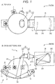
- Fig. 1 is a diagram illustrating an optical configuration of a reflection characteristic measuring device according to first and second embodiments.
- Fig. 2 is a diagram illustrating an electrical configuration of the reflection characteristic measuring device according to the first and second embodiments.
- a reflection characteristic measuring device Ma is a device that corrects a reflection characteristic using an error obtained by theoretical considerations.
- optical measurers 1 and 2 provided with an integrating sphere 22 as an example of a diffuse reflecting member, a correction light source 3, a correction luminance measurer 4, and a control processing unit 5a provided with a corrector 53a are included.
- a storage 6a, an input unit 7, an output unit 8, and an interface unit (IF unit) 9 are further included.
- the optical measurers 1 and 2 are devices that include a measurement aperture SA and measures, using a plurality of optical systems having mutually different geometries, a plurality of mutually different types of reflection characteristics by irradiating an object of measurement (not illustrated) facing the measurement aperture SA with measurement light and receiving reflected light.
- the reflection characteristic includes, for example, at least a plurality of values from a spectral reflectance, a gloss value, brilliance of the object of measurement that is an object to be measured, and the like, and the plurality of optical systems is configured to correspond to the plurality of types of reflection characteristics, respectively.
- the reflection characteristics are a gloss value measured in geometry of 60° gloss (60° illumination / 60° reception) and a spectral reflectance measured in geometry of diffuse illumination / 8° reception.
- the optical measurers 1 and 2 include a gloss measurer 1 that measures a gloss value using the geometry of 60° gloss (60° illumination / 60° reception), and a spectroscopic measurer 2 that measures the spectral reflectance using the geometry of diffuse illumination / 8° reception.
- the gloss measurer 1 includes a first light source 11, a first optical system that includes a first illumination optical system 12 and a first light receiving optical system 13 and forms the geometry of 60° gloss, a first measurer 14, and a reflection characteristic calculator 52 in the control processing unit 5a to be described later.
- the first light source 11 is a device that is connected to the control processing unit 5a and emits predetermined first illumination light under the control of the control processing unit 5a, which is configured to include, for example, a white LED.
- the first illumination optical system 12 is an optical system in which the first illumination light emitted from the first light source 11 is made incident and the first illumination light is collimated so that the object of measurement facing the measurement aperture SA is illuminated with the first illumination light from a single direction, which is configured to include, for example, one or a plurality of optical elements such as a lens.
- the first light receiving optical system 13 is an optical system that receives a first reflected light of the first illumination light reflected from the object of measurement from a single direction and concentrates and guide the first reflected light to the first measurer 14, which is configured to include, for example, one or a plurality of optical elements such as a lens.
- the first measurer 14 is a device that is connected to the control processing unit 5a and measures the first reflected light of the first illumination light emitted from the first light receiving optical system 13 under the control of the control processing unit 5a, which is configured to include, for example, a silicon photodiode for measuring intensity of the reflected light.
- the first measurer 14 outputs the measurement output to the control processing unit 5a.
- the spectroscopic measurer 2 includes a second light source 21, a second optical system that includes a second illumination optical system 22 and a second light receiving optical system 23 and forms the geometry of diffuse illumination / 8°, a second measurer 24, and the reflection characteristic calculator 52.
- the second light source 21 is a device that is connected to the control processing unit 5a and emits predetermined second illumination light for illuminating a diffuse reflecting surface of the second illumination optical system 22 under the control of the control processing unit 5a, which is configured to include, for example, a white LED.
- the second illumination optical system 22 is an optical system in which the second illumination light emitted from the second light source 21 is made incident and the object of measurement facing the measurement aperture SA is illuminated with diffused light of the second illumination light diffusely reflected by the diffuse reflecting surface, which is, for example, the integrating sphere 22 as an example of the diffuse reflecting member.
- the second light source 21 is disposed in a first recess formed at a predetermined position on the inner surface of the integrating sphere 22, and illuminates the diffuse reflecting surface covering the entire inner surface of the integrating sphere 22 with the second illumination light.
- the second light receiving optical system 23 is an optical system that receives a second reflected light of the diffused light reflected from the object of measurement and concentrates and guide the second reflected light to the second measurer 24, which is configured to include, for example, one or a plurality of optical elements such as a lens. More specifically, a mirror 231, and one or a plurality of lenses 232 are included.
- the mirror 231 is provided on an opening formed on the integrating sphere 22 at a position corresponding to the 8° direction of the measurement aperture SA, and reflects the second reflected light of the diffused light emitted from the opening.
- the lenses 232 guide the second reflected light of the diffused light reflected by the mirror 231 to the second measurer 24.
- the second measurer 24 is a device that is connected to the control processing unit 5a and spectroscopically measures, under the control of the control processing unit 5a, the second reflected light of the diffused light emitted from the second light receiving optical system 23, which is configured to include, for example, a spectrometer.
- the second measurer 24 includes a box-shaped casing 241 having a slit-like opening into which the second reflected light of the diffused light is made incident, a reflection type concave surface diffraction grating 242 that diffracts and reflects the second reflected light of the diffused light entered from the opening, and a line sensor 243 that has a plurality of line-shaped parallel photodiodes and receives the second reflected light diffracted and reflected by the reflection type concave surface diffraction grating 242.
- the second measurer 24 outputs the measurement output to the control processing unit 5a.
- the measurement aperture SA is shared by the gloss measurer 1 and the spectroscopic measurer 2, and only one measurement aperture SA is formed in the integrating sphere 22.
- the correction light source 3 is a device that is connected to the control processing unit 5a and emits predetermined correction illumination light for illuminating the diffuse reflecting surface of the integrating sphere 22 under the control of the control processing unit 5a, which is configured to include, for example, a white LED.
- the correction light source 3 is disposed in a second recess formed at a predetermined position different from the first recess on the inner surface of the integrating sphere 22, and illuminates the diffuse reflecting surface covering the entire inner surface of the integrating sphere 22 with the correction illumination light. Note that the correction light source 3 may also serve as the second light source 21.
- the correction luminance measurer 4 is a device that is connected to the control processing unit 5a and measures, under the control of the control processing unit 5a, luminance of the diffuse reflecting surface of the integrating sphere 22 illuminated with the correction illumination light of the correction light source 3 and luminance of the diffuse reflecting surface of the integrating sphere 22 illuminated with light reflected by the object of measurement illuminated with the first illumination light emitted from the first light source 11, which is configured to include, for example, a silicon photodiode for measuring intensity of the diffuse reflected light diffusely reflected by the diffuse reflecting surface.
- the correction luminance measurer 4 outputs the measurement output to the control processing unit 5a.
- the correction luminance measurer 4 is disposed in a third recess formed at a predetermined position different from the first and second recesses on the inner surface of the integrating sphere 22, and receives and measures the diffuse reflected light diffusely reflected by the diffuse reflecting surface covering the entire inner surface of the integrating sphere 22.
- a baffle may be provided between the correction light source 3 and the correction luminance measurer 4 so that the correction illumination light emitted from the correction light source 3 does not directly reach the correction luminance measurer 4.
- the spectroscopic measurer 2 includes a sensor for monitoring the inner surface luminance of the integrating sphere 22 to measure the spectral reflectance
- the correction luminance measurer 4 may also serve as this sensor.
- the spectral sensitivity of the correction luminance measurer 4 is preferably the same as the spectral sensitivity of the first measurer 14.
- an optical filter that compensates (corrects) for a difference between the spectral sensitivity of the correction luminance measurer 4 and the spectral sensitivity of the first measurer 14 is disposed on the light receiving side of the correction luminance measurer 4.
- the input unit 7 is a device that is connected to the control processing unit 5a and inputs various commands such as a command for providing an instruction on measurement of the object of measurement that is the object to be measured and various data necessary for measuring, for example, an input of an identifier of the object of measurement into the reflection characteristic measuring device Ma, which is, for example, a plurality of input switches to which predetermined functions are allocated.
- the output unit 8 is a device that is connected to the control processing unit 5a and outputs, under the control of the control processing unit 5a, the command and data input from the input unit 7 and the reflection characteristic of the object of measurement measured by the reflection characteristic measuring device Ma, which is, for example, a display device such as a CRT display, a liquid crystal display (LCD), and an organic EL display, and a printing device such as a printer.
- a display device such as a CRT display, a liquid crystal display (LCD), and an organic EL display
- a printing device such as a printer.
- the input unit 7 and the output unit 8 may constitute a touch panel.
- the input unit 7 is a position input device that detects and inputs an operation position such as a resistive film type and an electrostatic capacitance type
- the output unit 8 is a display device.
- a position input device is provided on the display surface of the display device, and one or a plurality of input content candidates that can be input to the display device is displayed.
- the position is detected by the position input device, and the display content displayed at the detected position is input to the reflection characteristic measuring device Ma as input content of the user operation.
- the reflection characteristic measuring device Ma easily operated by the user is provided.
- the IF unit 9 is a circuit that is connected to the control processing unit 5a and inputs/outputs data to/from an external device under the control of the control processing unit 5a, which is, for example, a serial communication RS-232C interface circuit, an interface circuit using the Bluetooth (registered trademark) standard, an interface circuit performing infrared communication using, for example, the infrared data association (IrDA) standard, and an interface circuit using the universal serial bus (USB) standard.
- a serial communication RS-232C interface circuit an interface circuit using the Bluetooth (registered trademark) standard
- an interface circuit performing infrared communication using, for example, the infrared data association (IrDA) standard
- USB universal serial bus
- the storage 6a is a circuit that is connected to the control processing unit 5a and stores various predetermined programs and various predetermined data under the control of the control processing unit 5a.
- Examples of the various predetermined programs include a control program for controlling each part of the reflection characteristic measuring device Ma, a reflection characteristic calculation program for obtaining a predetermined reflection characteristic, and a control processing program such as a correction program for correcting the reflection characteristic.
- the various predetermined data include data necessary for executing each program such as an identifier of the object of measurement and a measurement output from each part.
- the storage 6a as described above includes, for example, a read-only memory (ROM) that is a nonvolatile storage element, an electrically erasable programmable read-only memory (EEPROM) that is a rewritable nonvolatile storage element, and the like. Further, the storage 6a includes a random access memory (RAM) or the like serving as what is called a working memory of the control processing unit 5a, which stores data and the like generated during execution of the predetermined program.
- RAM random access memory
- the control processing unit 5a is a circuit for controlling each part of the reflection characteristic measuring device Ma according to a function of each part and obtaining the reflection characteristic of the object of measurement.
- the control processing unit 5a includes, for example, a central processing unit (CPU), and peripheral circuits thereof.
- the control processing unit 5a functionally includes a control unit 51, the reflection characteristic calculator 52, and the corrector 53a by the control processing program being executed.
- the control unit 51 controls each part of the reflection characteristic measuring device Ma according to the function of each part, and manages overall control of the reflection characteristic measuring device Ma.
- the reflection characteristic calculator 52 obtains a predetermined reflection characteristic on the basis of the measurement output of the optical measurers 1 and 2. More specifically, in the present embodiment, since the reflection characteristic is the gloss value measured in the geometry of 60° gloss (60° illumination/60° reception) and the spectral reflectance measured in the geometry of diffuse illumination/8° reception as described above, the reflection characteristic calculator 52 obtains the gloss value as one of the reflection characteristic using a known calculation method on the basis of the measurement output (first measurement output) of the first measurer 14, which is corrected as described later, and obtains the spectral reflectance as another one of the reflection characteristic using a known calculation method on the basis of the measurement output (second measurement output) of the second measurer 24. In this manner, the reflection characteristic calculator 52 according to the present embodiment functions as a gloss calculation unit for obtaining the gloss value and a spectroscopic calculation unit for obtaining the spectral reflectance.
- the corrector 53a corrects the reflection characteristic measured by the optical measurers 1 and 2 using an error E caused by light emitted from the object of measurement facing the measurement aperture SA being reflected by the diffuse reflecting surface of the integrating sphere 22 and illuminating the object of measurement facing the measurement aperture SA, and obtains the reflection characteristic of a true value or a value closer to the true value.
- the corrector 53a performs correction using the error E obtained by theoretical considerations.
- the corrector 53a obtains the error E on the basis of a measurement output (A1 measurement output) Bc of the correction luminance measurer 4 of a case where only the correction light source 3 emits the correction illumination light, a measurement output (A2 measurement output) B of the correction luminance measurer 4 of a case where only the first light source 11 emits the first illumination light, and a measurement output (A3 measurement output) Gd of the first measurer 14 of a case where only the correction light source 3 emits the correction illumination light, corrects a first measurement output Ge of the first measurer 14 of a case where only the first light source 14 emits the first illumination light using the obtained error E, and obtains a first measurement output G of a true value or a value closer to the true value.
- emission spectrum distribution of the first light source 14 (spectrum distribution of the first illumination light) is Sg
- emission spectrum distribution of the correction light source 3 (spectrum distribution of the correction illumination light) is Sc.
- reflection spectrum distribution in the reflected light of the diffuse reflected light directed toward the first light receiving optical system 13 is Rdg.
- reflection spectrum distribution in the reflected light of the first illumination light directed toward the integrating sphere 22 is R60s.
- the reflection spectrum distribution in the reflected light of the first illumination light directed toward the first light receiving optical system 13 is R60g.
- the spectral sensitivity of the first measurer 14 is Fg
- the spectral sensitivity of the correction luminance measurer 4 is Fc.
- an integrating sphere efficiency including influence of the reflection characteristic of the object of measurement is M
- the first measurement output Ge of the first measurer 14 of a case where only the first light source 11 emits the first illumination light is expressed by Formula 1.
- the A3 measurement output Gd of the first measurer 14 of a case where only the correction light source 3 emits the correction illumination light is expressed by Formula 2.
- the A2 measurement output B of the correction luminance measurer 4 of a case where only the first light source 11 emits the first illumination light is expressed by Formula 3. Further, the A1 measurement output Bc of the correction luminance measurer 4 of a case where only the correction light source 3 emits the correction illumination light is expressed by Formula 4.
- the first term on the right side of Formula 1 is a true value of the first measurement output G
- the second term on the right side of Formula 1 is the error E due to the recursive diffused illumination.
- the error E can be estimated by Formula 5, and thus the first measurement output G of the true value or a value closer to the true value can be obtained by Formula 6.
- E G d ⁇ B B c ⁇ ⁇ ⁇ 1 ⁇ 2 M ⁇ S g ⁇ R 60 ⁇ s ⁇ R dg ⁇ F g ⁇ d ⁇
- G G e ⁇ E
- the corrector 53a obtains the error E and obtains the first measurement output G of the true value or a value closer to the true value.
- the control processing unit 5a then obtains, using the reflection characteristic calculator 52, a gloss value Sh that is one of the reflection characteristic on the basis of the obtained first measurement output G of the true value or a value closer to the true value, and outputs the obtained gloss value Sh that is one of the reflection characteristic to the output unit 8 using the control unit 51.
- the control unit 51 outputs the obtained gloss value Sh that is one of the reflection characteristic from the IF unit 9 to an external device (such as USB memory).
- Fig. 3 is a flowchart illustrating the operation of the reflection characteristic measuring device according to first to sixth embodiments.
- Fig. 4 is a diagram for explaining the recursive diffused illumination.
- the reflection characteristic measuring device Ma is activated, necessary parts are initialized by the control processing unit 5a, and the control processing program is executed so that the control unit 51, the reflection characteristic calculator 52, and the corrector 53a are functionally configured in the control processing unit 5a.
- the reflection characteristic measuring device Ma obtains the gloss value Sh that is one of the reflection characteristic using the reflection characteristic calculator 52 of the control processing unit 5a (S4). More specifically, the reflection characteristic calculator 52 obtains the gloss value Sh using a known calculation method on the basis of the first measurement output G after correction, and stores it in the storage 6a.
- the control unit 51 of the control processing unit 5a may output the obtained gloss value Sh that is one of the reflection characteristic from the IF unit 9 to an external device (such as USB memory) as necessary.
- the reflection characteristic measuring device Ma When the user (operator) inputs an instruction on measurement of the spectral reflectance from the input unit 7, in a similar manner to a known spectrometer, the reflection characteristic measuring device Ma performs measurement using the spectroscopic measurer 2, obtains the spectral reflectance as one of the reflection characteristic using the reflection characteristic calculator 52 and a known calculation method on the basis of the second measurement output of the second measurer 24, and outputs the obtained spectral reflectance to the output unit 8.
- the reflection characteristic measuring device Ma since the reflection characteristic measuring device Ma according to the first embodiment includes the corrector 53a, even in the case of a device having a plurality of geometries including the diffuse reflecting member (integrating sphere in this case) 22, the error caused by the recursive diffused illumination can be reduced. That is, as illustrated in Fig.
- the reflected light is roughly divided into surface reflected light having been subject to Fresnel reflection on the surface and internal diffuse reflected light that once penetrates into the object to be measured, being absorbed by the object to be measured, for example, and then being emitted from the surface.
- the surface reflected light is scattered due to surface roughness of the object to be measured, and the light OP3-1 having an angle larger than an acceptance angle range of the first light receiving optical system 13 in the gloss measurer 1 is made incident on the integrating sphere 22.
- the major part OP3-2 of the internal diffuse reflected light is made incident on the integrating sphere 22.
- the light OP3 having been incident on the integrating sphere 22 repeats irregular reflection in the integrating sphere, and a part of the light OP4 illuminates the object of measurement (recursive diffused illumination).
- the light OP4 based on the recursive diffused illumination acts on the object of measurement.
- a part of the light OP5 is received by the first measurer 14 via the first light receiving optical system 13 of the gloss measurer 1 to generate the error E.
- the error E varies depending on the surface reflectance, the surface roughness, the internal diffuse reflectance, the integrating sphere efficiency, and the like of the object of measurement.
- the integrating sphere efficiency is a known value to some extent as it is determined by a design of the integrating sphere 22, each of the other values requires dedicated measurement, and such measurement is complex.
- the error E due to the recursive diffused illumination is obtained by the corrector 53a and correction is made on the basis of the error E as described above, whereby the error E due to the recursive diffused illumination can be reduced.
- the reflection characteristic measuring device Ma performs correction on the basis of the theoretical considerations, and is capable of reducing the error E caused by the recursive diffused illumination.
- Fig. 5 is a chart for explaining a correspondence relationship for obtaining an error stored in a reflection characteristic measuring device according to a second embodiment.
- a reflection characteristic measuring device Mb according to the second embodiment performs correction by obtaining an error E from a predetermined correspondence relationship obtained in advance.
- reflection characteristic measuring devices Mc to Mf according to third to sixth embodiments to be described later also perform correction by obtaining the error E from a predetermined correspondence relationship obtained in advance although the predetermined correspondence relationship is different.
- Such a reflection characteristic measuring device Mb includes, for example, as illustrated in Figs. 1 and 2 , optical measurers 1 and 2, a correction light source 3, a correction luminance measurer 4, a control processing unit 5b provided with a corrector 53b, and a storage 6b.
- an input unit 7, an output unit 8, and an IF unit 9 are further included.
- the optical measurers 1 and 2 are similar to the optical measurers 1 and 2, the correction light source 3, the correction luminance measurer 4, the input unit 7, the output unit 8, and the IF unit 9 in the reflection characteristic measuring device Mb according to the second embodiment are similar to the optical measurers 1 and 2, the correction light source 3, the correction luminance measurer 4, the input unit 7, the output unit 8, and the IF unit 9 in the reflection characteristic measuring device Ma according to the first embodiment, respectively, and descriptions thereof are omitted.
- the storage 6b functions in a similar manner to the storage 6a in the reflection characteristic measuring device Ma according to the first embodiment, and a correction information storage 61b that stores a predetermined first correspondence relationship, which is indicated by the short-dashed line in Fig. 2 , is further included in the second embodiment.
- the predetermined first correspondence relationship is a correspondence relationship between a measurement output of the correction luminance measurer (B measurement output) and the error E. More specifically, in the second embodiment, the predetermined first correspondence relationship is a B1 correspondence relationship between a measurement output of the correction luminance measurer 4 (B1 measurement output) of a case where only the correction light source 3 emits correction illumination light and the error E.
- a B1 correspondence relationship is obtained in advance by, for example, actual measurement using a plurality of samples, or simulation using, for example, an optical simulator.
- the first correspondence relationship obtained as described above is stored in the correction information storage 61b by a function formula thereof or in a lookup table.
- the B1 correspondence relationship is obtained in advance by simulation using the optical simulator, and is stored in the correction information storage 61b by the function formula thereof.
- the optical simulator include LightTools manufactured by Synopsys, Inc. In this simulation, simulation was carried out under a plurality of conditions in which glass or resin (plastic) was assumed as an object of measurement, surface reflectance was set to about 10%, and surface scattering and internal diffuse reflectance were varied. A plurality of simulation results of the B1 measurement output and the error E is indicated by the dot in Fig. 5 .
- a fitting function that fits the plurality of simulation results (the plurality of dots) of the B1 measurement output and the error E obtained in this manner is obtained as the B1 correspondence relationship using, for example, the least squares method, and the obtained fitting function is stored in the correction information storage 61b as a function formula expressing the B1 correspondence relationship.
- the plurality of samples is measured by a glossmeter alone, measured by the reflection characteristic measuring device Mb according to the second embodiment, and the error E is obtained by a difference between a measurement result of the glossmeter alone and a measurement result before correction of the reflection characteristic measuring device Mb according to the second embodiment, thereby obtaining the B1 correspondence relationship.
- simulation results of the case where metals were assumed as an object of measurement are also indicated by a plurality of triangles.
- simulation was carried out under a plurality of conditions in which the surface reflectance was set to 90% (corresponding to aluminum), and the surface scattering was varied. It is understood that, from this result, the B1 correspondence relationship differs depending on the type of the object of measurement (difference in the surface reflectance).
- the reflection characteristic measuring device Mb may be configured such that a plurality of B1 correspondence relationships corresponding to each of a plurality of types of (a plurality of surface reflectance of) the object of measurement is obtained in advance, the plurality of B1 correspondence relationships is stored in the correction information storage 61b in association with each of the plurality of types of (the plurality of surface reflectance of) the object of measurement, and a suitable B1 correspondence relationship is selected from the plurality of B1 correspondence relationships by a user or automatically by measuring the surface reflectance of the object of measurement at the time of measurement.
- the control processing unit 5b is a circuit for controlling each part of the reflection characteristic measuring device Mb according to a function of each part and obtaining the reflection characteristic of the object of measurement.
- the control processing unit 5b includes, for example, a CPU and peripheral circuits thereof.
- the control processing unit 5b functionally includes a control unit 51, a reflection characteristic calculator 52, and the corrector 53b by the control processing program being executed.
- the control unit 51 and the reflection characteristic calculator 52 according to the second embodiment are similar to the control unit 51 and the reflection characteristic calculator 52 according to the first embodiment, respectively, and descriptions thereof are omitted.
- the corrector 53b corrects the reflection characteristic measured by the optical measurers 1 and 2 using the error E caused by light emitted from the object of measurement facing the measurement aperture SA being reflected by the diffuse reflecting surface of the integrating sphere 22 and illuminating the object of measurement facing the measurement aperture SA, and obtains the reflection characteristic of a true value or a value closer to the true value.
- the corrector 53b obtains, from the B1 correspondence relationship, the error E corresponding to the B measurement output of the correction luminance measurer 4 at the time of measuring the object of measurement facing the measurement aperture SA, performs correction using the obtained error E, and obtains a reflection characteristic Sh (gloss value in the present embodiment) of the true value or a value closer to the true value.
- the reflection characteristic measuring device Mb when a power switch (not illustrated) is turned on, the reflection characteristic measuring device Mb is activated, necessary parts are initialized by the control processing unit 5b, and the control processing program is executed so that the control unit 51, the reflection characteristic calculator 52, and the corrector 53b are functionally configured in the control processing unit 5b.
- the reflection characteristic measuring device Mb then obtains the error E using the corrector 53b of the control processing unit 5b (S2b). More specifically, the corrector 53b obtains the error E corresponding to the B1 measurement output stored in the storage 6b from the B1 correspondence relationship stored in the correction information storage 61b, and stores it in the storage 6b.
- the gloss value Sh that is one of the reflection characteristic is obtained by the reflection characteristic calculator 52 of the control processing unit 5b on the basis of the first measurement output G after correction using a known calculation method, and the obtained gloss value Sh is stored in the storage 6b (S4).
- the reflection characteristic measuring device Mb the obtained gloss value G that is one of the reflection characteristic is output to the output unit 8 by the control unit 51 (S5), and the process is terminated.
- the reflection characteristic measuring device Mb since the reflection characteristic measuring device Mb according to the second embodiment includes the corrector 53b, even in the case of a device having a plurality of geometries including the diffuse reflecting member (integrating sphere in this case) 22, the error caused by the recursive diffused illumination can be reduced.
- correction is performed using the predetermined B1 correspondence relationship such as a relational expression and a lookup table obtained in advance as described above, whereby the error E caused by the recursive diffused illumination can be reduced.
- Fig. 6 is a diagram illustrating an optical configuration of a reflection characteristic measuring device according to a third embodiment.
- Fig. 7 is a diagram illustrating an electrical configuration of the reflection characteristic measuring device according to the third embodiment.
- Fig. 8 is a chart for explaining a correspondence relationship for obtaining an error stored in the reflection characteristic measuring device according to the third embodiment.
- a reflection characteristic measuring device Mc includes, for example, as illustrated in Figs. 6 and 7 , optical measurers 1 and 2, a correction luminance measurer 4, a control processing unit 5c provided with a corrector 53c, and a storage 6c.
- an input unit 7, an output unit 8, and an IF unit 9 are further included.
- the reflection characteristic measuring device Mc according to the third embodiment does not include a correction light source 3.
- optical measurers 1 and 2 the correction luminance measurer 4, the input unit 7, the output unit 8, and the IF unit 9 in the reflection characteristic measuring device Mc according to the third embodiment are similar to the optical measurers 1 and 2, the correction luminance measurer 4, the input unit 7, the output unit 8, and the IF unit 9 in the reflection characteristic measuring device Ma according to the first embodiment, respectively, and descriptions thereof are omitted.
- the storage 6c functions in a similar manner to the storage 6a in the reflection characteristic measuring device Ma according to the first embodiment, and a correction information storage 61c that stores a predetermined first correspondence relationship is further included in the third embodiment.
- the predetermined first correspondence relationship is a correspondence relationship between a measurement output of the correction luminance measurer (B measurement output) and an error E. More specifically, in the third embodiment, the predetermined first correspondence relationship is a B2 correspondence relationship between a measurement output of the correction luminance measurer 4 (B2 measurement output) of a case where only a first light source 11 emits first illumination light and the error E.
- a B2 correspondence relationship is obtained in advance by, for example, in a similar manner to the B1 correspondence relationship described above, actual measurement using a plurality of samples, or simulation using, for example, an optical simulator.
- the B2 correspondence relationship obtained in advance by the simulation using the optical simulator is illustrated in Fig. 8 as an example.
- the B2 correspondence relationship obtained as described above is stored in the correction information storage 61c by a function formula thereof or in a lookup table.
- the control processing unit 5c is a circuit for controlling each part of the reflection characteristic measuring device Mc according to a function of each part and obtaining a reflection characteristic of an object of measurement.
- the control processing unit 5c includes, for example, a CPU and peripheral circuits thereof.
- the control processing unit 5c functionally includes a control unit 51, a reflection characteristic calculator 52, and the corrector 53c by the control processing program being executed.
- the control unit 51 and the reflection characteristic calculator 52 according to the third embodiment are similar to the control unit 51 and the reflection characteristic calculator 52 according to the first embodiment, respectively, and descriptions thereof are omitted.
- the corrector 53c corrects the reflection characteristic measured by the optical measurers 1 and 2 using the error E caused by light emitted from the object of measurement facing a measurement aperture SA being reflected by a diffuse reflecting surface of an integrating sphere 22 and illuminating the object of measurement facing the measurement aperture SA, and obtains the reflection characteristic of a true value or a value closer to the true value.
- the corrector 53c obtains, from the B2 correspondence relationship, the error E corresponding to the B measurement output of the correction luminance measurer 4 at the time of measuring the object of measurement facing the measurement aperture SA, performs correction using the obtained error E, and obtains a reflection characteristic Sh (gloss value in the present embodiment) of the true value or a value closer to the true value.
- Sh spess value in the present embodiment
- the reflection characteristic measuring device Mc when a power switch (not illustrated) is turned on, the reflection characteristic measuring device Mc is activated, necessary parts are initialized by the control processing unit 5c, and the control processing program is executed so that the control unit 51, the reflection characteristic calculator 52, and the corrector 53c are functionally configured in the control processing unit 5c.
- the reflection characteristic measuring device Mc then obtains the error E using the corrector 53c of the control processing unit 5c (S2c). More specifically, the corrector 53c obtains the error E corresponding to the B2 measurement output stored in the storage 6c from the B2 correspondence relationship stored in the correction information storage 61c, and stores it in the storage 6c.
- the reflection characteristic calculator 52 of the control processing unit 5c obtains the gloss value Sh that is one of the reflection characteristic on the basis of a first measurement output G after correction and stores it in the storage 6c (S4)
- the control unit 51 outputs the obtained gloss value G that is one of the reflection characteristic to the output unit 8 (S5), and the process is terminated.
- the reflection characteristic measuring device Mc since the reflection characteristic measuring device Mc according to the third embodiment includes the corrector 53c, even in the case of a device having a plurality of geometries including a diffuse reflecting member (integrating sphere in this case) 22, the error caused by recursive diffused illumination can be reduced.
- correction is performed using the predetermined B2 correspondence relationship such as a relational expression and a lookup table obtained in advance as described above, whereby the error E caused by the recursive diffused illumination can be reduced.
- Fig. 9 is a diagram illustrating an optical configuration of a reflection characteristic measuring device according to fourth and fifth embodiments.
- Fig. 10 is a diagram illustrating an electrical configuration of the reflection characteristic measuring device according to the fourth and fifth embodiments.
- Fig. 11 is a chart for explaining a correspondence relationship for obtaining an error stored in the reflection characteristic measuring device according to the fourth embodiment.
- a reflection characteristic measuring device Md according to the fourth embodiment includes, for example, as illustrated in Figs. 9 and 10 , optical measurers 1 and 2, a correction light source 3, a control processing unit 5d provided with a corrector 53d, and a storage 6d.
- an input unit 7, an output unit 8, and an IF unit 9 are further included.
- the reflection characteristic measuring device Md according to the fourth embodiment does not include a correction luminance measurer 4.
- optical measurers 1 and 2 the correction light source 3, the input unit 7, the output unit 8, and the IF unit 9 in the reflection characteristic measuring device Md according to the fourth embodiment are similar to the optical measurers 1 and 2, the correction light source 3, the input unit 7, the output unit 8, and the IF unit 9 in the reflection characteristic measuring device Ma according to the first embodiment, respectively, and descriptions thereof are omitted.
- the storage 6d functions in a similar manner to the storage 6a in the reflection characteristic measuring device Ma according to the first embodiment, and a correction information storage 61d that stores a predetermined second correspondence relationship is further included in the fourth embodiment.
- the predetermined second correspondence relationship is a correspondence relationship between a measurement output of a first measurer 14 (C measurement output) and an error E. More specifically, in the fourth embodiment, the predetermined second correspondence relationship is a C1 correspondence relationship between a measurement output of the first measurer 14 (C1 measurement output) of a case where only the correction light source 3 emits correction illumination light and the error E.
- Such a C1 correspondence relationship is obtained in advance by, for example, in a similar manner to the B1 correspondence relationship described above, actual measurement using a plurality of samples, or simulation using, for example, an optical simulator. In a similar manner to the B1 correspondence relationship, the C1 correspondence relationship obtained in advance by the simulation using the optical simulator is illustrated in Fig. 11 as an example.
- the C1 correspondence relationship obtained as described above is stored in the correction information storage 61d by a function formula thereof or in a lookup table.
- the control processing unit 5d is a circuit for controlling each part of the reflection characteristic measuring device Md according to a function of each part and obtaining a reflection characteristic of an object of measurement.
- the control processing unit 5d includes, for example, a CPU and peripheral circuits thereof.
- the control processing unit 5d functionally includes a control unit 51, a reflection characteristic calculator 52, and the corrector 53d by the control processing program being executed.
- the control unit 51 and the reflection characteristic calculator 52 according to the fourth embodiment are similar to the control unit 51 and the reflection characteristic calculator 52 according to the first embodiment, and descriptions thereof are omitted.
- the corrector 53d corrects the reflection characteristic measured by the optical measurers 1 and 2 using the error E caused by light emitted from the object of measurement facing a measurement aperture SA being reflected by a diffuse reflecting surface of an integrating sphere 22 and illuminating the object of measurement facing the measurement aperture SA, and obtains the reflection characteristic of a true value or a value closer to the true value.
- the corrector 53d obtains, from the C1 correspondence relationship, the error E corresponding to the C measurement output of the first measurer 14 at the time of measuring the object of measurement facing the measurement aperture SA, performs correction using the obtained error E, and obtains a reflection characteristic Sh (gloss value in the present embodiment) of the true value or a value closer to the true value.
- Sh spess value in the present embodiment
- the reflection characteristic measuring device Md when a power switch (not illustrated) is turned on, the reflection characteristic measuring device Md is activated, necessary parts are initialized by the control processing unit 5d, and the control processing program is executed so that the control unit 51, the reflection characteristic calculator 52, and the corrector 53d are functionally configured in the control processing unit 5d.
- the reflection characteristic measuring device Md then obtains the error E using the corrector 53d of the control processing unit 5d (S2d). More specifically, the corrector 53d obtains the error E corresponding to the C measurement output stored in the storage 6d from the C1 correspondence relationship stored in the correction information storage 61d, and stores it in the storage 6d.
- the reflection characteristic calculator 52 of the control processing unit 5d obtains the gloss value Sh that is one of the reflection characteristic on the basis of a first measurement output G after correction and stores it in the storage 6c (S4)
- the control unit 51 outputs the obtained gloss value G that is one of the reflection characteristic to the output unit 8 (S5), and the process is terminated.
- the reflection characteristic measuring device Md since the reflection characteristic measuring device Md according to the fourth embodiment includes the corrector 53d, even in the case of a device having a plurality of geometries including a diffuse reflecting member (integrating sphere in this case) 22, the error caused by recursive diffused illumination can be reduced.
- correction is performed using the predetermined C1 correspondence relationship such as a relational expression and a lookup table obtained in advance as described above, whereby the error E caused by the recursive diffused illumination can be reduced.
- the correction luminance measurer of the reflection characteristic measuring device Md has spectral sensitivity same as that of the first measurer 14 when the error E is obtained from a first correspondence relationship.
- the corrector 53d multiplies the C measurement output of the first measurer 14 by what is called visibility V ⁇ (spectral luminous efficiency, corresponding to Y in the XYZ color space) so that the spectral sensitivity of the first measurer 14 is made equal to the spectral sensitivity of the first measurer 14, and the error E corresponding to the C measurement output multiplied by V ⁇ is obtained from the C1 correspondence relationship.
- Fig. 12 is a chart for explaining a correspondence relationship for obtaining an error stored in a reflection characteristic measuring device according to a fifth embodiment.
- a reflection characteristic measuring device Me includes, for example, as illustrated in Figs. 9 and 10 , optical measurers 1 and 2, a correction light source 3, a control processing unit 5e provided with a corrector 53e, and a storage 6e.
- an input unit 7, an output unit 8, and an IF unit 9 are further included.
- the reflection characteristic measuring device Me according to the fifth embodiment does not include a correction luminance measurer 4.
- the optical measurers 1 and 2, the correction light source 3, the input unit 7, the output unit 8, and the IF unit 9 in the reflection characteristic measuring device Me according to the fifth embodiment are similar to the optical measurers 1 and 2, the correction light source 3, the input unit 7, the output unit 8, and the IF unit 9 in the reflection characteristic measuring device Ma according to the first embodiment, respectively, and descriptions thereof are omitted.
- the storage 6e functions in a similar manner to the storage 6a in the reflection characteristic measuring device Ma according to the first embodiment, and a correction information storage 61e that stores a predetermined second correspondence relationship is further included in the fifth embodiment.
- the predetermined second correspondence relationship is a correspondence relationship between a measurement output of a second measurer 24 (D measurement output) and an error E. More specifically, in the fifth embodiment, the predetermined second correspondence relationship is a D1 correspondence relationship between a measurement output of the second measurer 24 (D1 measurement output) of a case where only the correction light source 3 emits correction illumination light and the error E.
- a D1 correspondence relationship is obtained in advance by, for example, in a similar manner to the B1 correspondence relationship described above, actual measurement using a plurality of samples, or simulation using, for example, an optical simulator.
- the D1 correspondence relationship obtained in advance by the simulation using the optical simulator is illustrated in Fig. 12 as an example.
- the D1 correspondence relationship obtained as described above is stored in the correction information storage 61e by a function formula thereof or in a lookup table.
- the control processing unit 5e is a circuit for controlling each part of the reflection characteristic measuring device Me according to a function of each part and obtaining a reflection characteristic of an object of measurement.
- the control processing unit 5e includes, for example, a CPU and peripheral circuits thereof.
- the control processing unit 5e functionally includes a control unit 51, a reflection characteristic calculator 52, and the corrector 53e by the control processing program being executed.
- the control unit 51 and the reflection characteristic calculator 52 according to the fifth embodiment are similar to the control unit 51 and the reflection characteristic calculator 52 according to the first embodiment, respectively, and descriptions thereof are omitted.
- the corrector 53e corrects the reflection characteristic measured by the optical measurers 1 and 2 using the error E caused by light emitted from the object of measurement facing a measurement aperture SA being reflected by a diffuse reflecting surface of an integrating sphere 22 and illuminating the object of measurement facing the measurement aperture SA, and obtains the reflection characteristic of a true value or a value closer to the true value.
- the corrector 53e obtains, from the D1 correspondence relationship, the error E corresponding to the D measurement output of the second measurer 24 at the time of measuring the object of measurement facing the measurement aperture SA, performs correction using the obtained error E, and obtains a reflection characteristic Sh (gloss value in the present embodiment) of the true value or a value closer to the true value.
- Sh spess value in the present embodiment
- the reflection characteristic measuring device Me when a power switch (not illustrated) is turned on, the reflection characteristic measuring device Me is activated, necessary parts are initialized by the control processing unit 5e, and the control processing program is executed so that the control unit 51, the reflection characteristic calculator 52, and the corrector 53e are functionally configured in the control processing unit 5e.
- the reflection characteristic measuring device Me then obtains the error E using the corrector 53e of the control processing unit 5e (S2e). More specifically, the corrector 53e obtains the error E corresponding to the D1 measurement output stored in the storage 6e from the D1 correspondence relationship stored in the correction information storage 61e, and stores it in the storage 6e.
- the reflection characteristic measuring device Me since the reflection characteristic measuring device Me according to the fifth embodiment includes the corrector 53e, even in the case of a device having a plurality of geometries including a diffuse reflecting member (integrating sphere in this case) 22, the error caused by recursive diffused illumination can be reduced.
- correction is performed using the predetermined D1 correspondence relationship such as a relational expression and a lookup table obtained in advance as described above, whereby the error E caused by the recursive diffused illumination can be reduced.
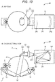
- Fig. 13 is a diagram illustrating an optical configuration of a reflection characteristic measuring device according to a sixth embodiment.
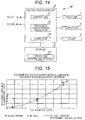
- Fig. 14 is a diagram illustrating an electrical configuration of the reflection characteristic measuring device according to the sixth embodiment.
- Fig. 15 is a chart for explaining a correspondence relationship for obtaining an error stored in the reflection characteristic measuring device according to a sixth embodiment.
- a reflection characteristic measuring device Mf according to the sixth embodiment includes, for example, as illustrated in Figs. 13 and 14 , optical measurers 1 and 2, a control processing unit 5fprovided with a corrector 53f, and a storage 6f.
- an input unit 7, an output unit 8, and an IF unit 9 are further included.
- the reflection characteristic measuring device Mf according to the sixth embodiment does not include a correction light source 3 and a correction luminance measurer 4.
- optical measurers 1 and 2 the input unit 7, the output unit 8, and the IF unit 9 in the reflection characteristic measuring device Mf according to the sixth embodiment are similar to the optical measurers 1 and 2, the input unit 7, the output unit 8, and the IF unit 9 in the reflection characteristic measuring device Ma according to the first embodiment, respectively, and descriptions thereof are omitted.
- the storage 6f functions in a similar manner to the storage 6a in the reflection characteristic measuring device Ma according to the first embodiment, and a correction information storage 61f that stores a predetermined second correspondence relationship is further included in the sixth embodiment.
- the predetermined second correspondence relationship is a correspondence relationship between a measurement output of a second measurer 24 (D measurement output) and an error E. More specifically, in the sixth embodiment, the predetermined second correspondence relationship is a D2 correspondence relationship between a measurement output of the second measurer 24 (D2 measurement output) of a case where only a first light source 11 emits first illumination light and the error E.
- a D2 correspondence relationship is obtained in advance by, for example, in a similar manner to the B1 correspondence relationship described above, actual measurement using a plurality of samples, or simulation using, for example, an optical simulator.
- the D2 correspondence relationship obtained in advance by the simulation using the optical simulator is illustrated in Fig. 15 as an example.
- the D2 correspondence relationship obtained as described above is stored in the correction information storage 61f by a function formula thereof or in a lookup table.
- the control processing unit 5f is a circuit for controlling each part of the reflection characteristic measuring device Mf according to a function of each part and obtaining a reflection characteristic of an object of measurement.
- the control processing unit 5f includes, for example, a CPU and peripheral circuits thereof.
- the control processing unit 5f functionally includes a control unit 51, a reflection characteristic calculator 52, and the corrector 53f by the control processing program being executed.
- the control unit 51 and the reflection characteristic calculator 52 according to the fifth embodiment are similar to the control unit 51 and the reflection characteristic calculator 52 according to the first embodiment, respectively, and descriptions thereof are omitted.
- the corrector 53f corrects the reflection characteristic measured by the optical measurers 1 and 2 using the error E caused by light emitted from the object of measurement facing a measurement aperture SA being reflected by a diffuse reflecting surface of an integrating sphere 22 and illuminating the object of measurement facing the measurement aperture SA, and obtains the reflection characteristic of a true value or a value closer to the true value.
- the corrector 53f obtains, from the D2 correspondence relationship, the error E corresponding to the D measurement output of the second measurer 24 at the time of measuring the object of measurement facing the measurement aperture SA, performs correction using the obtained error E, and obtains a reflection characteristic Sh (gloss value in the present embodiment) of the true value or a value closer to the true value.
- Sh spess value in the present embodiment
- the reflection characteristic measuring device Mf when a power switch (not illustrated) is turned on, the reflection characteristic measuring device Mf is activated, necessary parts are initialized by the control processing unit 5f, and the control processing program is executed so that the control unit 51, the reflection characteristic calculator 52, and the corrector 53f are functionally configured in the control processing unit 5f.
- a user inputs an instruction on measurement of the gloss value from the input unit 7
- measurement is performed by each unit in Fig. 3 (S1f). More specifically, in the reflection characteristic measuring device Me, a first light source 14 is turned on by the control unit 51, the D2 measurement output of the second measurer 24 in this case is obtained and stored in the storage 6f, and a first measurement output of a first measurer 14 in this case is obtained and stored in the storage 6f.
- the reflection characteristic measuring device Mf then obtains the error E using the corrector 53f of the control processing unit 5f (S2f), More specifically, the corrector 53f obtains the error E corresponding to the D2 measurement output stored in the storage 6f from the D2 correspondence relationship stored in the correction information storage 61f, and stores it in the storage 6f.
- the reflection characteristic calculator 52 of the control processing unit 5f obtains the gloss value Sh that is one of the reflection characteristic on the basis of a first measurement output G after correction and stores it in the storage 6f (S4)
- the control unit 51 outputs the obtained gloss value G that is one of the reflection characteristic to the output unit 8 (S5), and the process is terminated.
- the reflection characteristic measuring device Mf since the reflection characteristic measuring device Mf according to the sixth embodiment includes the corrector 53f, even in the case of a device having a plurality of geometries including a diffuse reflecting member (integrating sphere in this case) 22, the error caused by recursive diffused illumination can be reduced.
- correction is performed using the predetermined D2 correspondence relationship such as a relational expression and a lookup table obtained in advance as described above, whereby the error E caused by the recursive diffused illumination can be reduced.
- the second measurer 24 of the reflection characteristic measuring devices Me and Mf has spectral sensitivity same as that of the first measurer 14 when the error E is obtained from the second correspondence relationship.
- the corrector 53e multiplies the D1 measurement output of the second measurer 24 by what is called visibility V ⁇ (spectral luminous efficiency, corresponding to Y in the XYZ color space) so that the spectral sensitivity of the second measurer 24 is made equal to the spectral sensitivity of the first measurer 14, and the error E corresponding to the D1 measurement output multiplied by V ⁇ is obtained from the D1 correspondence relationship.
- the corrector 53f multiplies the D2 measurement output of the second measurer 24 by the visibility V ⁇ so that the spectral sensitivity of the second measurer 24 is made equal to the spectral sensitivity of the first measurer 14, and the error E corresponding to the D2 measurement output multiplied by V ⁇ is obtained from the D2 correspondence relationship.
- the spectral sensitivity of the second measurer 24 is made equal to the spectral sensitivity of the first measurer 14 when the error E is obtained from the second correspondence relationship, the error E can be obtained more accurately, and the error E caused by the recursive diffused illumination can be further reduced.
- a reflection characteristic measuring device includes an optical measurer that includes a measurement aperture and measures, using a plurality of optical systems having mutually different geometries, a plurality of mutually different types of reflection characteristics by irradiating an object of measurement facing the measurement aperture with measurement light and receiving the reflected light.
- the optical measurer includes a diffuse reflecting member having a diffuse reflecting surface that performs diffuse reflection in at least one of the plurality of optical systems.
- the reflection characteristic measuring device further includes a corrector that corrects the reflection characteristic measured by the optical measurer using an error generated by light emitted from the object of measurement facing the measurement aperture being reflected by the diffuse reflecting surface and illuminating the object of measurement facing the measurement aperture.
- the diffuse reflecting member is preferably an integrating sphere.
- the optical measurer preferably includes a first light source that emits first illumination light, a first optical system including a first illumination optical system into which the first illumination light emitted from the first light source unit is made incident and illuminates the object of measurement facing the measurement aperture with the first illumination light from a single direction and a first light receiving optical system that receives a first reflected light of the first illumination light reflected by the object of measurement from a single direction, a first measurer that measures the first reflected light of the first illumination light emitted from the first light receiving optical system, and a gloss calculation unit that obtains a gloss value as the reflection characteristic on the basis of a first measurement output of the first measurer.
- the optical measurer preferably includes a second light source that emits second illumination light for illuminating the diffuse reflecting surface, a second optical system including a second illumination optical system into which the second illumination light emitted from the second light source unit is made incident and illuminates the object of measurement facing the measurement aperture with diffused light of the second illumination light diffusely reflected by the diffuse reflecting surface and a second light receiving optical system that receives second reflected light of the diffused light reflected by the object of measurement, a second measurer that spectroscopically measures the second reflected light of the diffused light emitted from the second light receiving optical system, and a spectroscopic calculation unit that obtains a spectral reflectance as the reflection characteristic on the basis of a second measurement output of the second measurer.
- reflection characteristic measuring device includes the corrector, errors caused by recursive diffused illumination can be reduced in the reflection characteristic measuring device including a diffuse reflecting member and having a plurality of geometries.
- the above-described reflection characteristic measuring device further includes a correction light source that emits correction illumination light for illuminating the diffuse reflecting surface, and a correction luminance measurer that measures luminance of the diffuse reflecting surface, in which the optical measurer includes a first light source that emits first illumination light, a first optical system including a first illumination optical system into which the first illumination light emitted from the first light source unit is made incident and illuminates the object of measurement facing the measurement aperture with the first illumination light from a single direction and a first light receiving optical system that receives a first reflected light of the first illumination light reflected by the object of measurement from a single direction, a first measurer that measures the first reflected light of the first illumination light emitted from the first light receiving optical system, and a reflection characteristic calculator that obtains the reflection characteristic on the basis of a first measurement output of the first measurer, the corrector obtains the error (E) on the basis of an A1 measurement output (Bc) of the correction luminance measurer of a case where only the correction light source emit
- Such a reflection characteristic measuring device is capable of performing correction by theoretical considerations and reducing errors caused by the recursive diffused illumination.
- the above-described reflection characteristic measuring device further includes a correction luminance measurer that measures luminance of the diffuse reflecting surface, and a first correction information storage that stores first correspondence relationship between B measurement output of the correction luminance measurer and the error, in which the corrector obtains the error corresponding to the B measurement output of the correction luminance measurer at the time of measuring the object of measurement facing the measurement aperture from the first correspondence relationship, and corrects the reflection characteristic measured by the optical measurer using the obtained error.
- a correction light source that emits correction illumination light for illuminating the diffuse reflecting surface
- the optical measurer includes a first light source that emits first illumination light, a first optical system including a first illumination optical system into which the first illumination light emitted from the first light source unit is made incident and illuminates the object of measurement facing the measurement aperture with the first illumination light from a single direction and a first light receiving optical system that receives a first reflected light of the first illumination light reflected by the object of measurement from a single direction, a first measurer that measures the first reflected light of the first illumination light emitted from the first light receiving optical system, and a gloss calculation unit that obtains a gloss value as the reflection characteristic on the basis of a first measurement output of the first measurer, and the first correction information storage stores a B1 correspondence relationship between a B1 measurement output of the correction luminance measurer of a case where only the correction light source emits the correction illumination light and the error as the first correspondence relationship.
- the optical measurer includes the first light source that emits the first illumination light, the first optical system including the first illumination optical system into which the first illumination light emitted from the first light source unit is made incident and illuminates the object of measurement facing the measurement aperture with the first illumination light from a single direction and the first light receiving optical system that receives the first reflected light of the first illumination light reflected by the object of measurement from a single direction, the first measurer that measures the first reflected light of the first illumination light emitted from the first light receiving optical system, and the gloss calculation unit that obtains the gloss value as the reflection characteristic on the basis of the first measurement output of the first measurer, and the first correction information storage stores a B2 correspondence relationship between a B2 measurement output of the correction luminance measurer of a case where only the first light source emits the first illumination light and the error as the first correspondence relationship.
- the correction luminance measurer has spectral sensitivity same as spectral sensitivity of the first
- correction is performed using the predetermined first correspondence relationship such as a relational expression and a lookup table obtained in advance, whereby the error caused by the recursive diffused illumination can be reduced.
- the above-described reflection characteristic measuring device further includes a correction light source that emits correction illumination light for illuminating the diffuse reflecting surface, and a second correction information storage that stores a second correspondence relationship between a C measurement output of the first measurer or a D measurement output of the second measurer and the error,
- the optical measurer includes a first light source that emits first illumination light, a first optical system including a first illumination optical system into which the first illumination light emitted from the first light source unit is made incident and illuminates the object of measurement facing the measurement aperture with the first illumination light from a single direction and a first light receiving optical system that receives a first reflected light of the first illumination light reflected by the object of measurement from a single direction, a first measurer that measures the first reflected light of the first illumination light emitted from the first light receiving optical system, a second light source that emits second illumination light for illuminating the diffuse reflecting surface, a second optical system including a second illumination optical system into which the second illumination light emitted from the second light
- the correction light source preferably also serves as the second light source.
- the optical measurer further includes a reflection characteristic calculator that obtains a first type of the reflection characteristic on the basis of the first measurement output of the first measurer and obtains a second type of the reflection characteristic different from the first type on the basis of the second measurement output of the second measurer, and the corrector corrects the first measurement output of the first measurer using the obtained error.
- the second correction information storage stores a C1 correspondence relationship between a C1 measurement output of the first measurer of a case where only the correction light source emits the correction illumination light and the error as the second correspondence relationship.
- the second correction information storage stores a D1 correspondence relationship between a D1 measurement output of the second measurer of a case where only the correction light source emits the correction illumination light and the error as the second correspondence relationship.
- the second correction information storage stores a D2 correspondence relationship between a D2 measurement output of the second measurer of a case where only the first light source emits the first illumination light and the error as the second correspondence relationship.
- correction is performed using the predetermined second correspondence relationship such as a relational expression and a lookup table obtained in advance, whereby the error caused by the recursive diffused illumination can be reduced.
- the second measurer has spectral sensitivity same as spectral sensitivity of the first measurer at the time of obtaining the error from the second correspondence relationship.
- the correction luminance measurer has the spectral sensitivity same as the spectral sensitivity of the first measurer at the time of obtaining the error from the first correspondence relationship
- a reflection characteristic measuring device that illuminates an object of measurement, which is an object to be measured, and measures its reflection characteristic can be provided.
Landscapes
- Physics & Mathematics (AREA)
- General Physics & Mathematics (AREA)
- Spectroscopy & Molecular Physics (AREA)
- Chemical & Material Sciences (AREA)
- Life Sciences & Earth Sciences (AREA)
- Analytical Chemistry (AREA)
- Biochemistry (AREA)
- General Health & Medical Sciences (AREA)
- Health & Medical Sciences (AREA)
- Immunology (AREA)
- Pathology (AREA)
- Engineering & Computer Science (AREA)
- Mathematical Physics (AREA)
- Theoretical Computer Science (AREA)
- Investigating Or Analysing Materials By Optical Means (AREA)
- Spectrometry And Color Measurement (AREA)
Abstract
Description
- The present invention relates to a reflection characteristic measuring device that illuminates an object of measurement, which is an object to be measured, and measures its reflection characteristic.
- Conventionally, a reflection characteristic measuring device that measures a reflection characteristic has been known. Examples of the reflection characteristic include, for example, a spectral reflectance, a gloss value, brilliance, and the like. The spectral reflectance is a reflectance for each wavelength. The gloss value is a numerical value that represents a degree of glossiness, and is obtained according to a ratio between intensity of specular reflection light and intensity of scattered reflection light. The brilliance is a numerical value representing a glittering appearance caused by a brightening agent (such as aluminum flake) included in a metallic paint, a pearl paint, and the like. Those various reflection characteristics are defined by, for example, standards and the like, and there is geometry suitable for the measurement. For example, the spectral reflectance is measured using geometry such as 45° illumination / 0° reception, 45° illumination / multi-angle reception, and diffuse illumination / 8° reception. Further, for example, the gloss value is measured using geometry of 20° gloss (20° illumination / 20° reception), 60° gloss (60° illumination / 60° reception), and 85° gloss (85° illumination / 85° reception). Therefore, conventionally, in general, the spectral reflectance has been measured by, for example, a spectroscope for spectral reflectance measurement, the gloss value has been measured by, for example, a glossmeter for gloss measurement, and the brilliance has been measured by a measuring device for brilliance measurement. In recent years, for example, as disclosed in
Patent Literature 1, those plurality of measuring devices is integrated into one measuring device, and a device capable of measuring a plurality of types of reflection characteristics with respect to the same part of an object of measurement, which is an object to be measured, has been developed. - Meanwhile, for the measurement of the reflection characteristic, there is measurement using a diffuse reflecting member having a diffuse reflecting surface that performs diffuse reflection such as an integrating sphere. For example, in a case where the spectral reflectance is measured using the geometry of diffuse illumination / 8° reception, an integrating sphere is used to generate the diffuse illumination. As described above, in a case where the plurality of measuring devices is integrated into one measuring device, the integrated measuring device includes a plurality of geometries to make it possible to measure a plurality of types of reflection characteristics. As a result, there may be a case where the integrated measuring device is provided with a geometry including the diffuse reflecting member (first geometry) as necessary for the measurement, and a geometry not including the diffuse reflecting member (second geometry) unnecessary for the measurement. In such a case, at the time of measuring using the second geometry, the light in the second geometry is diffusely reflected by the diffuse reflecting surface of the first geometry, and the diffusely reflected light and the light caused by the diffused light may be measured using the second geometry at times, which results in a measurement error. As an example, in a case where the geometry of diffuse illumination/8° reception and the geometry of 60° gloss (60° illumination/60° reception) are integrated, while the illumination light in the geometry of 60° gloss is reflected by a surface of the object to be measured and most of the reflected light is received and measured by a light receiving part in the geometry of 60° gloss, a part of the reflected light is made incident on the integrating sphere in the geometry of diffuse illumination/8° reception. For example, the reflected light is roughly divided into surface reflected light having been subject to Fresnel reflection on the surface and internal diffuse reflected light that once penetrates into the object to be measured, being absorbed by the object to be measured, for example, and then being emitted from the surface. The surface reflected light is scattered due to surface roughness of the object to be measured, and light having an angle larger than an acceptance angle range at the geometry of 60° gloss is made incident on the integrating sphere. Most of the internal diffuse reflected light is made incident on the integrating sphere. The light having been incident on the integrating sphere repeats irregular reflection in the integrating sphere, and a part of the light illuminates the object to be measured (recursive diffused illumination). The light based on the recursive diffused illumination acts on the object to be measured in a similar manner to the illumination light in the geometry of 60° gloss described above. As a result, a part of the light is received by the light receiving part in the geometry of 60° gloss, which results in a measurement error.
- Patent Literature 1:
US 7741629 B2 - The present invention has been conceived in view of the circumstances described above, and an object of the present invention is to provide a reflection characteristic measuring device capable of reducing errors caused by recursive diffused illumination in a reflection characteristic measuring device having a plurality of geometries.
- The reflection characteristic measuring device according to the present invention is a device that includes a diffuse reflecting surface and measures a plurality of mutually different types of reflection characteristics by using a plurality of optical systems having mutually different geometries, which corrects the reflection characteristics to be measured by an error generated by light emitted from an object of measurement being reflected by the diffuse reflecting surface and illuminating the object of measurement. Therefore, the reflection characteristic measuring device according to the present invention can reduce the error caused by the recursive diffused illumination.
- Those and other objects, features and advantages of the present invention will become apparent from the following detailed descriptions and the accompanying drawings.
-
-
Fig. 1 is a diagram illustrating an optical configuration of a reflection characteristic measuring device according to first and second embodiments. -
Fig. 2 is a diagram illustrating an electrical configuration of the reflection characteristic measuring device according to the first and second embodiments. -
Fig. 3 is a flowchart illustrating operation of the reflection characteristic measuring device according to first to sixth embodiments. -
Fig. 4 is a diagram for explaining recursive diffused illumination. -
Fig. 5 is a chart for explaining a correspondence relationship for obtaining an error stored in the reflection characteristic measuring device according to the second embodiment. -
Fig. 6 is a diagram illustrating an optical configuration of the reflection characteristic measuring device according to the third embodiment. -
Fig. 7 is a diagram illustrating an electrical configuration of the reflection characteristic measuring device according to the third embodiment. -
Fig. 8 is a chart for explaining a correspondence relationship for obtaining an error stored in the reflection characteristic measuring device according to the third embodiment. -
Fig. 9 is a diagram illustrating an optical configuration of the reflection characteristic measuring device according to the fourth and fifth embodiments. -
Fig. 10 is a diagram illustrating an electrical configuration of the reflection characteristic measuring device according to the fourth and fifth embodiments. -
Fig. 11 is a chart for explaining a correspondence relationship for obtaining an error stored in the reflection characteristic measuring device according to the fourth embodiment. -
Fig. 12 is a chart for explaining a correspondence relationship for obtaining an error stored in the reflection characteristic measuring device according to the fifth embodiment. -
Fig. 13 is a diagram illustrating an optical configuration of the reflection characteristic measuring device according to the sixth embodiment. -
Fig. 14 is a diagram illustrating an electrical configuration of the reflection characteristic measuring device according to the sixth embodiment. -
Fig. 15 is a chart for explaining a correspondence relationship for obtaining an error stored in the reflection characteristic measuring device according to the sixth embodiment. - Hereinafter, embodiments of the present invention will be described with reference to the accompanying drawings. Note that configurations denoted by the same reference signs in each drawing indicate the same configurations, and descriptions thereof are omitted as appropriate. In the present description, a generic term is denoted by a reference sign with a suffix being omitted, and an individual configuration is denoted by a reference sign with a suffix.
- A reflection characteristic measuring device according to an embodiment includes an optical measurer that includes a measurement aperture and measures, using a plurality of optical systems having mutually different geometries, a plurality of mutually different types of reflection characteristics by irradiating an object of measurement facing the measurement aperture with measurement light and receiving reflected light. The reflection characteristic includes at least a plurality of values from, for example, a spectral reflectance, a gloss value, and brilliance of the object of measurement that is an object to be measured. The optical measurer includes a diffuse reflecting member having a diffuse reflecting surface that performs diffuse reflection in at least one of the plurality of optical systems. The diffuse reflecting member is, for example, an integrating sphere. The integrating sphere is a hollow sphere in which a material having high diffuse reflectance covers the inside thereof. Examples of the material having high diffuse reflectance include magnesium oxide, aluminum oxide, barium sulfate, magnesium sulfate, zinc oxide, and the like. A coating agent including a material having a high diffuse reflectance is applied to the inner surface of the sphere, thereby forming the diffuse reflecting surface. The reflection characteristic measuring device further includes a corrector that corrects the reflection characteristic measured by the optical measurer using an error generated by light emitted from the object of measurement facing the measurement aperture being reflected by the diffuse reflecting surface and illuminating the object of measurement facing the measurement aperture. Since such a reflection characteristic measuring device includes the corrector, errors caused by recursive diffused illumination can be reduced in the reflection characteristic measuring device having a plurality of geometries.
- Hereinafter, such a reflection characteristic measuring device will be described in more detail with reference to first to sixth embodiments. Note that, in each drawing, a configuration of a reflection characteristic measuring device M (Ma) according to a first embodiment is indicated by adding a suffix "a" to the reference sign, a configuration of a reflection characteristic measuring device M (Mb) according to a second embodiment is indicated by adding a suffix "b" to the reference sign, a configuration of a reflection characteristic measuring device M (Mc) according to a third embodiment is indicated by adding a suffix "c" to the reference sign, a configuration of a reflection characteristic measuring device M (Md) according to a fourth embodiment is indicated by adding a suffix "d" to the reference sign, a configuration of a reflection characteristic measuring device M (Me) according to a fifth embodiment is indicated by adding a suffix "e" to the reference sign, and a configuration of a reflection characteristic measuring device M (Mf) according to a sixth embodiment is indicated by adding a suffix "f" to the reference sign.
-
Fig. 1 is a diagram illustrating an optical configuration of a reflection characteristic measuring device according to first and second embodiments.Fig. 2 is a diagram illustrating an electrical configuration of the reflection characteristic measuring device according to the first and second embodiments. - A reflection characteristic measuring device Ma according to the first embodiment is a device that corrects a reflection characteristic using an error obtained by theoretical considerations. For example, as illustrated in
Figs. 1 and2 ,optical measurers sphere 22 as an example of a diffuse reflecting member, a correctionlight source 3, acorrection luminance measurer 4, and acontrol processing unit 5a provided with acorrector 53a are included. In the example illustrated inFigs. 1 and2 , astorage 6a, aninput unit 7, anoutput unit 8, and an interface unit (IF unit) 9 are further included. - The
optical measurers optical measurers gloss measurer 1 that measures a gloss value using the geometry of 60° gloss (60° illumination / 60° reception), and aspectroscopic measurer 2 that measures the spectral reflectance using the geometry of diffuse illumination / 8° reception. - The
gloss measurer 1 includes afirst light source 11, a first optical system that includes a first illuminationoptical system 12 and a first light receivingoptical system 13 and forms the geometry of 60° gloss, afirst measurer 14, and a reflectioncharacteristic calculator 52 in thecontrol processing unit 5a to be described later. Thefirst light source 11 is a device that is connected to thecontrol processing unit 5a and emits predetermined first illumination light under the control of thecontrol processing unit 5a, which is configured to include, for example, a white LED. The first illuminationoptical system 12 is an optical system in which the first illumination light emitted from thefirst light source 11 is made incident and the first illumination light is collimated so that the object of measurement facing the measurement aperture SA is illuminated with the first illumination light from a single direction, which is configured to include, for example, one or a plurality of optical elements such as a lens. The first light receivingoptical system 13 is an optical system that receives a first reflected light of the first illumination light reflected from the object of measurement from a single direction and concentrates and guide the first reflected light to thefirst measurer 14, which is configured to include, for example, one or a plurality of optical elements such as a lens. Thefirst measurer 14 is a device that is connected to thecontrol processing unit 5a and measures the first reflected light of the first illumination light emitted from the first light receivingoptical system 13 under the control of thecontrol processing unit 5a, which is configured to include, for example, a silicon photodiode for measuring intensity of the reflected light. Thefirst measurer 14 outputs the measurement output to thecontrol processing unit 5a. - The
spectroscopic measurer 2 includes a secondlight source 21, a second optical system that includes a second illuminationoptical system 22 and a second light receivingoptical system 23 and forms the geometry of diffuse illumination / 8°, asecond measurer 24, and the reflectioncharacteristic calculator 52. The secondlight source 21 is a device that is connected to thecontrol processing unit 5a and emits predetermined second illumination light for illuminating a diffuse reflecting surface of the second illuminationoptical system 22 under the control of thecontrol processing unit 5a, which is configured to include, for example, a white LED. The second illuminationoptical system 22 is an optical system in which the second illumination light emitted from the secondlight source 21 is made incident and the object of measurement facing the measurement aperture SA is illuminated with diffused light of the second illumination light diffusely reflected by the diffuse reflecting surface, which is, for example, the integratingsphere 22 as an example of the diffuse reflecting member. The secondlight source 21 is disposed in a first recess formed at a predetermined position on the inner surface of the integratingsphere 22, and illuminates the diffuse reflecting surface covering the entire inner surface of the integratingsphere 22 with the second illumination light. The second light receivingoptical system 23 is an optical system that receives a second reflected light of the diffused light reflected from the object of measurement and concentrates and guide the second reflected light to thesecond measurer 24, which is configured to include, for example, one or a plurality of optical elements such as a lens. More specifically, amirror 231, and one or a plurality oflenses 232 are included. Themirror 231 is provided on an opening formed on the integratingsphere 22 at a position corresponding to the 8° direction of the measurement aperture SA, and reflects the second reflected light of the diffused light emitted from the opening. Thelenses 232 guide the second reflected light of the diffused light reflected by themirror 231 to thesecond measurer 24. Thesecond measurer 24 is a device that is connected to thecontrol processing unit 5a and spectroscopically measures, under the control of thecontrol processing unit 5a, the second reflected light of the diffused light emitted from the second light receivingoptical system 23, which is configured to include, for example, a spectrometer. More specifically, thesecond measurer 24 includes a box-shapedcasing 241 having a slit-like opening into which the second reflected light of the diffused light is made incident, a reflection type concavesurface diffraction grating 242 that diffracts and reflects the second reflected light of the diffused light entered from the opening, and aline sensor 243 that has a plurality of line-shaped parallel photodiodes and receives the second reflected light diffracted and reflected by the reflection type concavesurface diffraction grating 242. Thesecond measurer 24 outputs the measurement output to thecontrol processing unit 5a. - The measurement aperture SA is shared by the
gloss measurer 1 and thespectroscopic measurer 2, and only one measurement aperture SA is formed in the integratingsphere 22. - The correction
light source 3 is a device that is connected to thecontrol processing unit 5a and emits predetermined correction illumination light for illuminating the diffuse reflecting surface of the integratingsphere 22 under the control of thecontrol processing unit 5a, which is configured to include, for example, a white LED. The correctionlight source 3 is disposed in a second recess formed at a predetermined position different from the first recess on the inner surface of the integratingsphere 22, and illuminates the diffuse reflecting surface covering the entire inner surface of the integratingsphere 22 with the correction illumination light. Note that the correctionlight source 3 may also serve as the secondlight source 21. - The
correction luminance measurer 4 is a device that is connected to thecontrol processing unit 5a and measures, under the control of thecontrol processing unit 5a, luminance of the diffuse reflecting surface of the integratingsphere 22 illuminated with the correction illumination light of the correctionlight source 3 and luminance of the diffuse reflecting surface of the integratingsphere 22 illuminated with light reflected by the object of measurement illuminated with the first illumination light emitted from thefirst light source 11, which is configured to include, for example, a silicon photodiode for measuring intensity of the diffuse reflected light diffusely reflected by the diffuse reflecting surface. Thecorrection luminance measurer 4 outputs the measurement output to thecontrol processing unit 5a. Thecorrection luminance measurer 4 is disposed in a third recess formed at a predetermined position different from the first and second recesses on the inner surface of the integratingsphere 22, and receives and measures the diffuse reflected light diffusely reflected by the diffuse reflecting surface covering the entire inner surface of the integratingsphere 22. A baffle may be provided between the correctionlight source 3 and thecorrection luminance measurer 4 so that the correction illumination light emitted from the correctionlight source 3 does not directly reach thecorrection luminance measurer 4. Further, in a case where thespectroscopic measurer 2 includes a sensor for monitoring the inner surface luminance of the integratingsphere 22 to measure the spectral reflectance, thecorrection luminance measurer 4 may also serve as this sensor. - In order to obtain an error more accurately, the spectral sensitivity of the
correction luminance measurer 4 is preferably the same as the spectral sensitivity of thefirst measurer 14. In this case, for example, an optical filter that compensates (corrects) for a difference between the spectral sensitivity of thecorrection luminance measurer 4 and the spectral sensitivity of thefirst measurer 14 is disposed on the light receiving side of thecorrection luminance measurer 4. - The
input unit 7 is a device that is connected to thecontrol processing unit 5a and inputs various commands such as a command for providing an instruction on measurement of the object of measurement that is the object to be measured and various data necessary for measuring, for example, an input of an identifier of the object of measurement into the reflection characteristic measuring device Ma, which is, for example, a plurality of input switches to which predetermined functions are allocated. Theoutput unit 8 is a device that is connected to thecontrol processing unit 5a and outputs, under the control of thecontrol processing unit 5a, the command and data input from theinput unit 7 and the reflection characteristic of the object of measurement measured by the reflection characteristic measuring device Ma, which is, for example, a display device such as a CRT display, a liquid crystal display (LCD), and an organic EL display, and a printing device such as a printer. - Note that the
input unit 7 and theoutput unit 8 may constitute a touch panel. In a case where the touch panel is constituted, theinput unit 7 is a position input device that detects and inputs an operation position such as a resistive film type and an electrostatic capacitance type, and theoutput unit 8 is a display device. In this touch panel, a position input device is provided on the display surface of the display device, and one or a plurality of input content candidates that can be input to the display device is displayed. When a user touches a display position displaying the input content to be input, the position is detected by the position input device, and the display content displayed at the detected position is input to the reflection characteristic measuring device Ma as input content of the user operation. With such a touch panel, since the user can easily understand the input operation intuitively, the reflection characteristic measuring device Ma easily operated by the user is provided. - The
IF unit 9 is a circuit that is connected to thecontrol processing unit 5a and inputs/outputs data to/from an external device under the control of thecontrol processing unit 5a, which is, for example, a serial communication RS-232C interface circuit, an interface circuit using the Bluetooth (registered trademark) standard, an interface circuit performing infrared communication using, for example, the infrared data association (IrDA) standard, and an interface circuit using the universal serial bus (USB) standard. - The
storage 6a is a circuit that is connected to thecontrol processing unit 5a and stores various predetermined programs and various predetermined data under the control of thecontrol processing unit 5a. Examples of the various predetermined programs include a control program for controlling each part of the reflection characteristic measuring device Ma, a reflection characteristic calculation program for obtaining a predetermined reflection characteristic, and a control processing program such as a correction program for correcting the reflection characteristic. The various predetermined data include data necessary for executing each program such as an identifier of the object of measurement and a measurement output from each part. Thestorage 6a as described above includes, for example, a read-only memory (ROM) that is a nonvolatile storage element, an electrically erasable programmable read-only memory (EEPROM) that is a rewritable nonvolatile storage element, and the like. Further, thestorage 6a includes a random access memory (RAM) or the like serving as what is called a working memory of thecontrol processing unit 5a, which stores data and the like generated during execution of the predetermined program. - The
control processing unit 5a is a circuit for controlling each part of the reflection characteristic measuring device Ma according to a function of each part and obtaining the reflection characteristic of the object of measurement. Thecontrol processing unit 5a includes, for example, a central processing unit (CPU), and peripheral circuits thereof. Thecontrol processing unit 5a functionally includes acontrol unit 51, the reflectioncharacteristic calculator 52, and thecorrector 53a by the control processing program being executed. - The
control unit 51 controls each part of the reflection characteristic measuring device Ma according to the function of each part, and manages overall control of the reflection characteristic measuring device Ma. - The reflection
characteristic calculator 52 obtains a predetermined reflection characteristic on the basis of the measurement output of theoptical measurers characteristic calculator 52 obtains the gloss value as one of the reflection characteristic using a known calculation method on the basis of the measurement output (first measurement output) of thefirst measurer 14, which is corrected as described later, and obtains the spectral reflectance as another one of the reflection characteristic using a known calculation method on the basis of the measurement output (second measurement output) of thesecond measurer 24. In this manner, the reflectioncharacteristic calculator 52 according to the present embodiment functions as a gloss calculation unit for obtaining the gloss value and a spectroscopic calculation unit for obtaining the spectral reflectance. - The
corrector 53a corrects the reflection characteristic measured by theoptical measurers sphere 22 and illuminating the object of measurement facing the measurement aperture SA, and obtains the reflection characteristic of a true value or a value closer to the true value. In the present embodiment, thecorrector 53a performs correction using the error E obtained by theoretical considerations. More specifically, thecorrector 53a obtains the error E on the basis of a measurement output (A1 measurement output) Bc of thecorrection luminance measurer 4 of a case where only the correctionlight source 3 emits the correction illumination light, a measurement output (A2 measurement output) B of thecorrection luminance measurer 4 of a case where only thefirst light source 11 emits the first illumination light, and a measurement output (A3 measurement output) Gd of thefirst measurer 14 of a case where only the correctionlight source 3 emits the correction illumination light, corrects a first measurement output Ge of thefirst measurer 14 of a case where only thefirst light source 14 emits the first illumination light using the obtained error E, and obtains a first measurement output G of a true value or a value closer to the true value. - More specifically, emission spectrum distribution of the first light source 14 (spectrum distribution of the first illumination light) is Sg, and emission spectrum distribution of the correction light source 3 (spectrum distribution of the correction illumination light) is Sc. In a case where the diffuse reflected light from the integrating
sphere 22 illuminates the object of measurement, reflection spectrum distribution in the reflected light of the diffuse reflected light directed toward the first light receivingoptical system 13 is Rdg. In a case where the first illumination light from thefirst light source 11 illuminates the object of measurement, reflection spectrum distribution in the reflected light of the first illumination light directed toward the integratingsphere 22 is R60s. In a case where the first illumination light from thefirst light source 11 illuminates the object of measurement, the reflection spectrum distribution in the reflected light of the first illumination light directed toward the first light receivingoptical system 13 is R60g. The spectral sensitivity of thefirst measurer 14 is Fg, and the spectral sensitivity of thecorrection luminance measurer 4 is Fc. In a case where an integrating sphere efficiency including influence of the reflection characteristic of the object of measurement is M, the first measurement output Ge of thefirst measurer 14 of a case where only thefirst light source 11 emits the first illumination light is expressed byFormula 1. The A3 measurement output Gd of thefirst measurer 14 of a case where only the correctionlight source 3 emits the correction illumination light is expressed byFormula 2. The A2 measurement output B of thecorrection luminance measurer 4 of a case where only thefirst light source 11 emits the first illumination light is expressed byFormula 3. Further, the A1 measurement output Bc of thecorrection luminance measurer 4 of a case where only the correctionlight source 3 emits the correction illumination light is expressed byFormula 4.
[Formula 1]


- The first term on the right side of
Formula 1 is a true value of the first measurement output G, and the second term on the right side ofFormula 1 is the error E due to the recursive diffused illumination. FromFormulae Formula 5, and thus the first measurement output G of the true value or a value closer to the true value can be obtained by Formula 6.
[Formula 5]

- As described above, the
corrector 53a according to the first embodiment obtains the error E and obtains the first measurement output G of the true value or a value closer to the true value. - The
control processing unit 5a then obtains, using the reflectioncharacteristic calculator 52, a gloss value Sh that is one of the reflection characteristic on the basis of the obtained first measurement output G of the true value or a value closer to the true value, and outputs the obtained gloss value Sh that is one of the reflection characteristic to theoutput unit 8 using thecontrol unit 51. Alternatively, as necessary, thecontrol unit 51 outputs the obtained gloss value Sh that is one of the reflection characteristic from theIF unit 9 to an external device (such as USB memory). - Next, operation of the reflection characteristic measuring device Ma according to the first embodiment will be described.
Fig. 3 is a flowchart illustrating the operation of the reflection characteristic measuring device according to first to sixth embodiments.Fig. 4 is a diagram for explaining the recursive diffused illumination. - First, when a power switch (not illustrated) is turned on, the reflection characteristic measuring device Ma is activated, necessary parts are initialized by the
control processing unit 5a, and the control processing program is executed so that thecontrol unit 51, the reflectioncharacteristic calculator 52, and thecorrector 53a are functionally configured in thecontrol processing unit 5a. - When the user (operator) inputs an instruction on measurement of the gloss value from the
input unit 7, measurement is performed by each unit inFig. 3 (S1a). More specifically, in the reflection characteristic measuring device Ma, only the correctionlight source 3 is turned on by thecontrol unit 51, and the A1 measurement output Bc of thecorrection luminance measurer 4 and the A3 measurement output Gd of thefirst measurer 14 in this case are obtained and stored in thestorage 6a. Next, in the reflection characteristic measuring device Ma, only thefirst light source 11 is turned on by thecontrol unit 51, and the A2 measurement output B of thecorrection luminance measurer 4 and the first measurement output Ge of thefirst measurer 14 in this case are obtained and stored in thestorage 6a. - The reflection characteristic measuring device Ma then obtains the error E using the
corrector 53a of thecontrol processing unit 5a (S2a). More specifically, thecorrector 53a obtains the error E from the A1 measurement output Bc, the A2 measurement output B, and the A3 measurement output Gd stored in thestorage 6a using Formula 5 mentioned above, and stores it in thestorage 6a (E = Gd × (B/Bc)). - Next, in the reflection characteristic measuring device Ma, the first measurement output Ge before correction stored in the
storage 6a is corrected by thecorrector 53a using the error E obtained in the processing S2a, and the first measurement output G after correction is obtained (S3). More specifically, thecorrector 53a obtains the first measurement output G after correction by Formula 6 mentioned above using the first measurement output Ge before correction and the error E stored in thestorage 6a (i.e., subtracting the error E from the first measurement output Ge before correction) (G = Ge - E). - Next, the reflection characteristic measuring device Ma obtains the gloss value Sh that is one of the reflection characteristic using the reflection
characteristic calculator 52 of thecontrol processing unit 5a (S4). More specifically, the reflectioncharacteristic calculator 52 obtains the gloss value Sh using a known calculation method on the basis of the first measurement output G after correction, and stores it in thestorage 6a. - Then, in the reflection characteristic measuring device Ma, the obtained gloss value Sh that is one of the reflection characteristic is output to the
output unit 8 by thecontrol unit 51 of thecontrol processing unit 5a (S5), and the process is terminated. Note that thecontrol unit 51 may output the obtained gloss value Sh that is one of the reflection characteristic from theIF unit 9 to an external device (such as USB memory) as necessary. - When the user (operator) inputs an instruction on measurement of the spectral reflectance from the
input unit 7, in a similar manner to a known spectrometer, the reflection characteristic measuring device Ma performs measurement using thespectroscopic measurer 2, obtains the spectral reflectance as one of the reflection characteristic using the reflectioncharacteristic calculator 52 and a known calculation method on the basis of the second measurement output of thesecond measurer 24, and outputs the obtained spectral reflectance to theoutput unit 8. - As described above, since the reflection characteristic measuring device Ma according to the first embodiment includes the
corrector 53a, even in the case of a device having a plurality of geometries including the diffuse reflecting member (integrating sphere in this case) 22, the error caused by the recursive diffused illumination can be reduced. That is, as illustrated inFig. 4 , in the case of measuring the gloss value of the object of measurement, when thefirst light source 11 of thegloss measurer 1 illuminates the object of measurement facing the measurement aperture SA with first illumination light OP1, the first illumination light OP1 is reflected by the surface of the object of measurement, and most of the reflected light OP2 is received by thefirst measurer 14 via the first light receivingoptical system 13 of thegloss measurer 1 and is measured, whereas a part of the reflected light OP3 (OP3-1 and OP3-2) is made incident on the integratingsphere 22 of thespectroscopic measurer 2. For example, the reflected light is roughly divided into surface reflected light having been subject to Fresnel reflection on the surface and internal diffuse reflected light that once penetrates into the object to be measured, being absorbed by the object to be measured, for example, and then being emitted from the surface. The surface reflected light is scattered due to surface roughness of the object to be measured, and the light OP3-1 having an angle larger than an acceptance angle range of the first light receivingoptical system 13 in thegloss measurer 1 is made incident on the integratingsphere 22. The major part OP3-2 of the internal diffuse reflected light is made incident on the integratingsphere 22. The light OP3 having been incident on the integratingsphere 22 repeats irregular reflection in the integrating sphere, and a part of the light OP4 illuminates the object of measurement (recursive diffused illumination). In a similar manner to the first illumination light OP1 described above, the light OP4 based on the recursive diffused illumination acts on the object of measurement. As a result, a part of the light OP5 is received by thefirst measurer 14 via the first light receivingoptical system 13 of thegloss measurer 1 to generate the error E. The error E varies depending on the surface reflectance, the surface roughness, the internal diffuse reflectance, the integrating sphere efficiency, and the like of the object of measurement. Although the integrating sphere efficiency is a known value to some extent as it is determined by a design of the integratingsphere 22, each of the other values requires dedicated measurement, and such measurement is complex. However, in the reflection characteristic measuring device Ma according to the first embodiment, the error E due to the recursive diffused illumination is obtained by thecorrector 53a and correction is made on the basis of the error E as described above, whereby the error E due to the recursive diffused illumination can be reduced. - Further, the reflection characteristic measuring device Ma according to the first embodiment performs correction on the basis of the theoretical considerations, and is capable of reducing the error E caused by the recursive diffused illumination.
-
Fig. 5 is a chart for explaining a correspondence relationship for obtaining an error stored in a reflection characteristic measuring device according to a second embodiment. - While the reflection characteristic measuring device Ma according to the first embodiment performs correction on the basis of theoretical considerations, a reflection characteristic measuring device Mb according to the second embodiment performs correction by obtaining an error E from a predetermined correspondence relationship obtained in advance. In a similar manner to the reflection characteristic measuring device Mb according to the second embodiment, reflection characteristic measuring devices Mc to Mf according to third to sixth embodiments to be described later also perform correction by obtaining the error E from a predetermined correspondence relationship obtained in advance although the predetermined correspondence relationship is different.
- Such a reflection characteristic measuring device Mb according to the second embodiment includes, for example, as illustrated in
Figs. 1 and2 ,optical measurers light source 3, acorrection luminance measurer 4, acontrol processing unit 5b provided with acorrector 53b, and astorage 6b. In the example illustrated inFigs. 1 and2 , aninput unit 7, anoutput unit 8, and anIF unit 9 are further included. Theoptical measurers light source 3, thecorrection luminance measurer 4, theinput unit 7, theoutput unit 8, and theIF unit 9 in the reflection characteristic measuring device Mb according to the second embodiment are similar to theoptical measurers light source 3, thecorrection luminance measurer 4, theinput unit 7, theoutput unit 8, and theIF unit 9 in the reflection characteristic measuring device Ma according to the first embodiment, respectively, and descriptions thereof are omitted. - The
storage 6b functions in a similar manner to thestorage 6a in the reflection characteristic measuring device Ma according to the first embodiment, and acorrection information storage 61b that stores a predetermined first correspondence relationship, which is indicated by the short-dashed line inFig. 2 , is further included in the second embodiment. - The predetermined first correspondence relationship is a correspondence relationship between a measurement output of the correction luminance measurer (B measurement output) and the error E. More specifically, in the second embodiment, the predetermined first correspondence relationship is a B1 correspondence relationship between a measurement output of the correction luminance measurer 4 (B1 measurement output) of a case where only the correction
light source 3 emits correction illumination light and the error E. Such a B1 correspondence relationship is obtained in advance by, for example, actual measurement using a plurality of samples, or simulation using, for example, an optical simulator. The first correspondence relationship obtained as described above is stored in thecorrection information storage 61b by a function formula thereof or in a lookup table. - In this case, the B1 correspondence relationship is obtained in advance by simulation using the optical simulator, and is stored in the
correction information storage 61b by the function formula thereof. Examples of the optical simulator include LightTools manufactured by Synopsys, Inc. In this simulation, simulation was carried out under a plurality of conditions in which glass or resin (plastic) was assumed as an object of measurement, surface reflectance was set to about 10%, and surface scattering and internal diffuse reflectance were varied. A plurality of simulation results of the B1 measurement output and the error E is indicated by the dot inFig. 5 . A fitting function that fits the plurality of simulation results (the plurality of dots) of the B1 measurement output and the error E obtained in this manner is obtained as the B1 correspondence relationship using, for example, the least squares method, and the obtained fitting function is stored in thecorrection information storage 61b as a function formula expressing the B1 correspondence relationship. - In a case where a plurality of samples is actually measured, the plurality of samples is measured by a glossmeter alone, measured by the reflection characteristic measuring device Mb according to the second embodiment, and the error E is obtained by a difference between a measurement result of the glossmeter alone and a measurement result before correction of the reflection characteristic measuring device Mb according to the second embodiment, thereby obtaining the B1 correspondence relationship.
- In addition, in
Fig. 5 , simulation results of the case where metals were assumed as an object of measurement are also indicated by a plurality of triangles. In this case, simulation was carried out under a plurality of conditions in which the surface reflectance was set to 90% (corresponding to aluminum), and the surface scattering was varied. It is understood that, from this result, the B1 correspondence relationship differs depending on the type of the object of measurement (difference in the surface reflectance). Therefore, the reflection characteristic measuring device Mb may be configured such that a plurality of B1 correspondence relationships corresponding to each of a plurality of types of (a plurality of surface reflectance of) the object of measurement is obtained in advance, the plurality of B1 correspondence relationships is stored in thecorrection information storage 61b in association with each of the plurality of types of (the plurality of surface reflectance of) the object of measurement, and a suitable B1 correspondence relationship is selected from the plurality of B1 correspondence relationships by a user or automatically by measuring the surface reflectance of the object of measurement at the time of measurement. - The
control processing unit 5b is a circuit for controlling each part of the reflection characteristic measuring device Mb according to a function of each part and obtaining the reflection characteristic of the object of measurement. Thecontrol processing unit 5b includes, for example, a CPU and peripheral circuits thereof. Thecontrol processing unit 5b functionally includes acontrol unit 51, a reflectioncharacteristic calculator 52, and thecorrector 53b by the control processing program being executed. Thecontrol unit 51 and the reflectioncharacteristic calculator 52 according to the second embodiment are similar to thecontrol unit 51 and the reflectioncharacteristic calculator 52 according to the first embodiment, respectively, and descriptions thereof are omitted. - The
corrector 53b corrects the reflection characteristic measured by theoptical measurers sphere 22 and illuminating the object of measurement facing the measurement aperture SA, and obtains the reflection characteristic of a true value or a value closer to the true value. In the present embodiment, thecorrector 53b obtains, from the B1 correspondence relationship, the error E corresponding to the B measurement output of thecorrection luminance measurer 4 at the time of measuring the object of measurement facing the measurement aperture SA, performs correction using the obtained error E, and obtains a reflection characteristic Sh (gloss value in the present embodiment) of the true value or a value closer to the true value. - Next, operation of the reflection characteristic measuring device Mb according to the second embodiment will be described. First, when a power switch (not illustrated) is turned on, the reflection characteristic measuring device Mb is activated, necessary parts are initialized by the
control processing unit 5b, and the control processing program is executed so that thecontrol unit 51, the reflectioncharacteristic calculator 52, and thecorrector 53b are functionally configured in thecontrol processing unit 5b. - When the user (operator) inputs an instruction on measurement of the gloss value from the
input unit 7, measurement is performed by each unit inFig. 3 (S1b). More specifically, in the reflection characteristic measuring device Mb, only the correctionlight source 3 is turned on by thecontrol unit 51, and the B1 measurement output of thecorrection luminance measurer 4 in this case is obtained and stored in thestorage 6b. Then, in the reflection characteristic measuring device Ma, only afirst light source 11 is turned on by thecontrol unit 51, and a first measurement output of afirst measurer 14 in this case is obtained and stored in thestorage 6b. - The reflection characteristic measuring device Mb then obtains the error E using the
corrector 53b of thecontrol processing unit 5b (S2b). More specifically, thecorrector 53b obtains the error E corresponding to the B1 measurement output stored in thestorage 6b from the B1 correspondence relationship stored in thecorrection information storage 61b, and stores it in thestorage 6b. - Next, in the reflection characteristic measuring device Mb, in a similar manner to the first embodiment, a first measurement output Ge before correction stored in the
storage 6b is corrected by thecorrector 53b using the error E obtained in the processing S2b, and a first measurement output G after correction is obtained (G = Ge - E, S3). - Next, in the reflection characteristic measuring device Mb, in a similar manner to the first embodiment, the gloss value Sh that is one of the reflection characteristic is obtained by the reflection
characteristic calculator 52 of thecontrol processing unit 5b on the basis of the first measurement output G after correction using a known calculation method, and the obtained gloss value Sh is stored in thestorage 6b (S4). - Then, in the reflection characteristic measuring device Mb, the obtained gloss value G that is one of the reflection characteristic is output to the
output unit 8 by the control unit 51 (S5), and the process is terminated. - As described above, since the reflection characteristic measuring device Mb according to the second embodiment includes the
corrector 53b, even in the case of a device having a plurality of geometries including the diffuse reflecting member (integrating sphere in this case) 22, the error caused by the recursive diffused illumination can be reduced. - Further, with the reflection characteristic measuring device Mb according to the second embodiment, correction is performed using the predetermined B1 correspondence relationship such as a relational expression and a lookup table obtained in advance as described above, whereby the error E caused by the recursive diffused illumination can be reduced.
- Next, another embodiment will be described.
-
Fig. 6 is a diagram illustrating an optical configuration of a reflection characteristic measuring device according to a third embodiment.Fig. 7 is a diagram illustrating an electrical configuration of the reflection characteristic measuring device according to the third embodiment.Fig. 8 is a chart for explaining a correspondence relationship for obtaining an error stored in the reflection characteristic measuring device according to the third embodiment. - A reflection characteristic measuring device Mc according to the third embodiment includes, for example, as illustrated in
Figs. 6 and7 ,optical measurers correction luminance measurer 4, acontrol processing unit 5c provided with acorrector 53c, and astorage 6c. In the example illustrated inFigs. 6 and7 , aninput unit 7, anoutput unit 8, and anIF unit 9 are further included. In other words, the reflection characteristic measuring device Mc according to the third embodiment does not include a correctionlight source 3. Theoptical measurers correction luminance measurer 4, theinput unit 7, theoutput unit 8, and theIF unit 9 in the reflection characteristic measuring device Mc according to the third embodiment are similar to theoptical measurers correction luminance measurer 4, theinput unit 7, theoutput unit 8, and theIF unit 9 in the reflection characteristic measuring device Ma according to the first embodiment, respectively, and descriptions thereof are omitted. - The
storage 6c functions in a similar manner to thestorage 6a in the reflection characteristic measuring device Ma according to the first embodiment, and acorrection information storage 61c that stores a predetermined first correspondence relationship is further included in the third embodiment. - The predetermined first correspondence relationship is a correspondence relationship between a measurement output of the correction luminance measurer (B measurement output) and an error E. More specifically, in the third embodiment, the predetermined first correspondence relationship is a B2 correspondence relationship between a measurement output of the correction luminance measurer 4 (B2 measurement output) of a case where only a
first light source 11 emits first illumination light and the error E. Such a B2 correspondence relationship is obtained in advance by, for example, in a similar manner to the B1 correspondence relationship described above, actual measurement using a plurality of samples, or simulation using, for example, an optical simulator. In a similar manner to the B1 correspondence relationship, the B2 correspondence relationship obtained in advance by the simulation using the optical simulator is illustrated inFig. 8 as an example. The B2 correspondence relationship obtained as described above is stored in thecorrection information storage 61c by a function formula thereof or in a lookup table. - The
control processing unit 5c is a circuit for controlling each part of the reflection characteristic measuring device Mc according to a function of each part and obtaining a reflection characteristic of an object of measurement. Thecontrol processing unit 5c includes, for example, a CPU and peripheral circuits thereof. Thecontrol processing unit 5c functionally includes acontrol unit 51, a reflectioncharacteristic calculator 52, and thecorrector 53c by the control processing program being executed. Thecontrol unit 51 and the reflectioncharacteristic calculator 52 according to the third embodiment are similar to thecontrol unit 51 and the reflectioncharacteristic calculator 52 according to the first embodiment, respectively, and descriptions thereof are omitted. - The
corrector 53c corrects the reflection characteristic measured by theoptical measurers sphere 22 and illuminating the object of measurement facing the measurement aperture SA, and obtains the reflection characteristic of a true value or a value closer to the true value. In the present embodiment, thecorrector 53c obtains, from the B2 correspondence relationship, the error E corresponding to the B measurement output of thecorrection luminance measurer 4 at the time of measuring the object of measurement facing the measurement aperture SA, performs correction using the obtained error E, and obtains a reflection characteristic Sh (gloss value in the present embodiment) of the true value or a value closer to the true value. - Next, operation of the reflection characteristic measuring device Mc according to the third embodiment will be described. First, when a power switch (not illustrated) is turned on, the reflection characteristic measuring device Mc is activated, necessary parts are initialized by the
control processing unit 5c, and the control processing program is executed so that thecontrol unit 51, the reflectioncharacteristic calculator 52, and thecorrector 53c are functionally configured in thecontrol processing unit 5c. - When a user (operator) inputs an instruction on measurement of the gloss value from the
input unit 7, measurement is performed by each unit inFig. 3 (S1c). More specifically, in the reflection characteristic measuring device Mc, thefirst light source 11 is turned on by thecontrol unit 51, the B2 measurement output of thecorrection luminance measurer 4 in this case is obtained and stored in thestorage 6c, and a first measurement output of afirst measurer 14 in this case is obtained and stored in thestorage 6c. - The reflection characteristic measuring device Mc then obtains the error E using the
corrector 53c of thecontrol processing unit 5c (S2c). More specifically, thecorrector 53c obtains the error E corresponding to the B2 measurement output stored in thestorage 6c from the B2 correspondence relationship stored in thecorrection information storage 61c, and stores it in thestorage 6c. - Then, in the reflection characteristic measuring device Mc, in a similar manner to the first embodiment, the
corrector 53c corrects a first measurement output Ge before correction stored in thestorage 6c using the error E obtained in the processing S2c (G = Ge - E, S3), the reflectioncharacteristic calculator 52 of thecontrol processing unit 5c obtains the gloss value Sh that is one of the reflection characteristic on the basis of a first measurement output G after correction and stores it in thestorage 6c (S4), thecontrol unit 51 outputs the obtained gloss value G that is one of the reflection characteristic to the output unit 8 (S5), and the process is terminated. - As described above, since the reflection characteristic measuring device Mc according to the third embodiment includes the
corrector 53c, even in the case of a device having a plurality of geometries including a diffuse reflecting member (integrating sphere in this case) 22, the error caused by recursive diffused illumination can be reduced. - Further, with the reflection characteristic measuring device Mc according to the third embodiment, correction is performed using the predetermined B2 correspondence relationship such as a relational expression and a lookup table obtained in advance as described above, whereby the error E caused by the recursive diffused illumination can be reduced.
- Next, another embodiment will be described.
-
Fig. 9 is a diagram illustrating an optical configuration of a reflection characteristic measuring device according to fourth and fifth embodiments.Fig. 10 is a diagram illustrating an electrical configuration of the reflection characteristic measuring device according to the fourth and fifth embodiments.Fig. 11 is a chart for explaining a correspondence relationship for obtaining an error stored in the reflection characteristic measuring device according to the fourth embodiment. - A reflection characteristic measuring device Md according to the fourth embodiment includes, for example, as illustrated in
Figs. 9 and10 ,optical measurers light source 3, acontrol processing unit 5d provided with acorrector 53d, and astorage 6d. In the example illustrated inFigs. 9 and10 , aninput unit 7, anoutput unit 8, and anIF unit 9 are further included. In other words, the reflection characteristic measuring device Md according to the fourth embodiment does not include acorrection luminance measurer 4. Theoptical measurers light source 3, theinput unit 7, theoutput unit 8, and theIF unit 9 in the reflection characteristic measuring device Md according to the fourth embodiment are similar to theoptical measurers light source 3, theinput unit 7, theoutput unit 8, and theIF unit 9 in the reflection characteristic measuring device Ma according to the first embodiment, respectively, and descriptions thereof are omitted. - The
storage 6d functions in a similar manner to thestorage 6a in the reflection characteristic measuring device Ma according to the first embodiment, and acorrection information storage 61d that stores a predetermined second correspondence relationship is further included in the fourth embodiment. - The predetermined second correspondence relationship is a correspondence relationship between a measurement output of a first measurer 14 (C measurement output) and an error E. More specifically, in the fourth embodiment, the predetermined second correspondence relationship is a C1 correspondence relationship between a measurement output of the first measurer 14 (C1 measurement output) of a case where only the correction
light source 3 emits correction illumination light and the error E. Such a C1 correspondence relationship is obtained in advance by, for example, in a similar manner to the B1 correspondence relationship described above, actual measurement using a plurality of samples, or simulation using, for example, an optical simulator. In a similar manner to the B1 correspondence relationship, the C1 correspondence relationship obtained in advance by the simulation using the optical simulator is illustrated inFig. 11 as an example. The C1 correspondence relationship obtained as described above is stored in thecorrection information storage 61d by a function formula thereof or in a lookup table. - The
control processing unit 5d is a circuit for controlling each part of the reflection characteristic measuring device Md according to a function of each part and obtaining a reflection characteristic of an object of measurement. Thecontrol processing unit 5d includes, for example, a CPU and peripheral circuits thereof. Thecontrol processing unit 5d functionally includes acontrol unit 51, a reflectioncharacteristic calculator 52, and thecorrector 53d by the control processing program being executed. Thecontrol unit 51 and the reflectioncharacteristic calculator 52 according to the fourth embodiment are similar to thecontrol unit 51 and the reflectioncharacteristic calculator 52 according to the first embodiment, and descriptions thereof are omitted. - The
corrector 53d corrects the reflection characteristic measured by theoptical measurers sphere 22 and illuminating the object of measurement facing the measurement aperture SA, and obtains the reflection characteristic of a true value or a value closer to the true value. In the present embodiment, thecorrector 53d obtains, from the C1 correspondence relationship, the error E corresponding to the C measurement output of thefirst measurer 14 at the time of measuring the object of measurement facing the measurement aperture SA, performs correction using the obtained error E, and obtains a reflection characteristic Sh (gloss value in the present embodiment) of the true value or a value closer to the true value. - Next, operation of the reflection characteristic measuring device Md according to the fourth embodiment will be described. First, when a power switch (not illustrated) is turned on, the reflection characteristic measuring device Md is activated, necessary parts are initialized by the
control processing unit 5d, and the control processing program is executed so that thecontrol unit 51, the reflectioncharacteristic calculator 52, and thecorrector 53d are functionally configured in thecontrol processing unit 5d. - When a user (operator) inputs an instruction on measurement of the gloss value from the
input unit 7, measurement is performed by each unit inFig. 3 (S1d). More specifically, in the reflection characteristic measuring device Md, only the correctionlight source 3 is turned on by thecontrol unit 51, and the C measurement output of thefirst measurer 14 in this case is obtained and stored in thestorage 6d. Then, in the reflection characteristic measuring device Md, only afirst light source 11 is turned on by thecontrol unit 51, and a first measurement output of thefirst measurer 14 in this case is obtained and stored in thestorage 6d. - The reflection characteristic measuring device Md then obtains the error E using the
corrector 53d of thecontrol processing unit 5d (S2d). More specifically, thecorrector 53d obtains the error E corresponding to the C measurement output stored in thestorage 6d from the C1 correspondence relationship stored in thecorrection information storage 61d, and stores it in thestorage 6d. - Then, in the reflection characteristic measuring device Md, in a similar manner to the first embodiment, the
corrector 53d corrects a first measurement output Ge before correction stored in thestorage 6d using the error E obtained in the processing S2d (G = Ge - E, S3), the reflectioncharacteristic calculator 52 of thecontrol processing unit 5d obtains the gloss value Sh that is one of the reflection characteristic on the basis of a first measurement output G after correction and stores it in thestorage 6c (S4), thecontrol unit 51 outputs the obtained gloss value G that is one of the reflection characteristic to the output unit 8 (S5), and the process is terminated. - As described above, since the reflection characteristic measuring device Md according to the fourth embodiment includes the
corrector 53d, even in the case of a device having a plurality of geometries including a diffuse reflecting member (integrating sphere in this case) 22, the error caused by recursive diffused illumination can be reduced. - Further, with the reflection characteristic measuring device Md according to the fourth embodiment, correction is performed using the predetermined C1 correspondence relationship such as a relational expression and a lookup table obtained in advance as described above, whereby the error E caused by the recursive diffused illumination can be reduced.
- It is preferable that the correction luminance measurer of the reflection characteristic measuring device Md according to the fourth embodiment has spectral sensitivity same as that of the
first measurer 14 when the error E is obtained from a first correspondence relationship. In this case, when the error E is obtained from the first correspondence relationship, thecorrector 53d multiplies the C measurement output of thefirst measurer 14 by what is called visibility Vλ (spectral luminous efficiency, corresponding to Y in the XYZ color space) so that the spectral sensitivity of thefirst measurer 14 is made equal to the spectral sensitivity of thefirst measurer 14, and the error E corresponding to the C measurement output multiplied by Vλ is obtained from the C1 correspondence relationship. In such a reflection characteristic measuring device Md, since the spectral sensitivity of thefirst measurer 14 is made equal to the spectral sensitivity of thefirst measurer 14 when the error E is obtained from the first correspondence relationship, the error E can be obtained more accurately, and the error E caused by the recursive diffused illumination can be further reduced. - Next, another embodiment will be described.
-
Fig. 12 is a chart for explaining a correspondence relationship for obtaining an error stored in a reflection characteristic measuring device according to a fifth embodiment. - A reflection characteristic measuring device Me according to the fifth embodiment includes, for example, as illustrated in
Figs. 9 and10 ,optical measurers light source 3, acontrol processing unit 5e provided with acorrector 53e, and astorage 6e. In the example illustrated inFigs. 9 and10 , aninput unit 7, anoutput unit 8, and anIF unit 9 are further included. In other words, the reflection characteristic measuring device Me according to the fifth embodiment does not include acorrection luminance measurer 4. Theoptical measurers light source 3, theinput unit 7, theoutput unit 8, and theIF unit 9 in the reflection characteristic measuring device Me according to the fifth embodiment are similar to theoptical measurers light source 3, theinput unit 7, theoutput unit 8, and theIF unit 9 in the reflection characteristic measuring device Ma according to the first embodiment, respectively, and descriptions thereof are omitted. - The
storage 6e functions in a similar manner to thestorage 6a in the reflection characteristic measuring device Ma according to the first embodiment, and acorrection information storage 61e that stores a predetermined second correspondence relationship is further included in the fifth embodiment. - The predetermined second correspondence relationship is a correspondence relationship between a measurement output of a second measurer 24 (D measurement output) and an error E. More specifically, in the fifth embodiment, the predetermined second correspondence relationship is a D1 correspondence relationship between a measurement output of the second measurer 24 (D1 measurement output) of a case where only the correction
light source 3 emits correction illumination light and the error E. Such a D1 correspondence relationship is obtained in advance by, for example, in a similar manner to the B1 correspondence relationship described above, actual measurement using a plurality of samples, or simulation using, for example, an optical simulator. In a similar manner to the B1 correspondence relationship, the D1 correspondence relationship obtained in advance by the simulation using the optical simulator is illustrated inFig. 12 as an example. The D1 correspondence relationship obtained as described above is stored in thecorrection information storage 61e by a function formula thereof or in a lookup table. - The
control processing unit 5e is a circuit for controlling each part of the reflection characteristic measuring device Me according to a function of each part and obtaining a reflection characteristic of an object of measurement. Thecontrol processing unit 5e includes, for example, a CPU and peripheral circuits thereof. Thecontrol processing unit 5e functionally includes acontrol unit 51, a reflectioncharacteristic calculator 52, and thecorrector 53e by the control processing program being executed. Thecontrol unit 51 and the reflectioncharacteristic calculator 52 according to the fifth embodiment are similar to thecontrol unit 51 and the reflectioncharacteristic calculator 52 according to the first embodiment, respectively, and descriptions thereof are omitted. - The
corrector 53e corrects the reflection characteristic measured by theoptical measurers sphere 22 and illuminating the object of measurement facing the measurement aperture SA, and obtains the reflection characteristic of a true value or a value closer to the true value. In the present embodiment, thecorrector 53e obtains, from the D1 correspondence relationship, the error E corresponding to the D measurement output of thesecond measurer 24 at the time of measuring the object of measurement facing the measurement aperture SA, performs correction using the obtained error E, and obtains a reflection characteristic Sh (gloss value in the present embodiment) of the true value or a value closer to the true value. - Next, operation of the reflection characteristic measuring device Me according to the fifth embodiment will be described. First, when a power switch (not illustrated) is turned on, the reflection characteristic measuring device Me is activated, necessary parts are initialized by the
control processing unit 5e, and the control processing program is executed so that thecontrol unit 51, the reflectioncharacteristic calculator 52, and thecorrector 53e are functionally configured in thecontrol processing unit 5e. - When a user (operator) inputs an instruction on measurement of the gloss value from the
input unit 7, measurement is performed by each unit inFig. 3 (S1e). More specifically, in the reflection characteristic measuring device Me, only the correctionlight source 3 is turned on by thecontrol unit 51, and the D1 measurement output of thesecond measurer 24 in this case is obtained and stored in thestorage 6e. Then, in the reflection characteristic measuring device Me, only afirst light source 11 is turned on by thecontrol unit 51, and a first measurement output of thefirst measurer 14 in this case is obtained and stored in thestorage 6e. - The reflection characteristic measuring device Me then obtains the error E using the
corrector 53e of thecontrol processing unit 5e (S2e). More specifically, thecorrector 53e obtains the error E corresponding to the D1 measurement output stored in thestorage 6e from the D1 correspondence relationship stored in thecorrection information storage 61e, and stores it in thestorage 6e. - Then, in the reflection characteristic measuring device Me, in a similar manner to the first embodiment, the
corrector 53e corrects a first measurement output Ge before correction stored in thestorage 6e using the error E obtained in the processing S2e (G = Ge - E, S3), the reflectioncharacteristic calculator 52 of thecontrol processing unit 5e obtains the gloss value Sh that is one of the reflection characteristic on the basis of a first measurement output G after correction and stores it in thestorage 6e (S4), thecontrol unit 51 outputs the obtained gloss value G that is one of the reflection characteristic to the output unit 8 (S5), and the process is terminated. - As described above, since the reflection characteristic measuring device Me according to the fifth embodiment includes the
corrector 53e, even in the case of a device having a plurality of geometries including a diffuse reflecting member (integrating sphere in this case) 22, the error caused by recursive diffused illumination can be reduced. - Further, with the reflection characteristic measuring device Me according to the fifth embodiment, correction is performed using the predetermined D1 correspondence relationship such as a relational expression and a lookup table obtained in advance as described above, whereby the error E caused by the recursive diffused illumination can be reduced.
- Next, another embodiment will be described.
-
Fig. 13 is a diagram illustrating an optical configuration of a reflection characteristic measuring device according to a sixth embodiment.Fig. 14 is a diagram illustrating an electrical configuration of the reflection characteristic measuring device according to the sixth embodiment.Fig. 15 is a chart for explaining a correspondence relationship for obtaining an error stored in the reflection characteristic measuring device according to a sixth embodiment. - A reflection characteristic measuring device Mf according to the sixth embodiment includes, for example, as illustrated in
Figs. 13 and14 ,optical measurers corrector 53f, and astorage 6f. In the example illustrated inFigs. 13 and14 , aninput unit 7, anoutput unit 8, and anIF unit 9 are further included. In other words, the reflection characteristic measuring device Mf according to the sixth embodiment does not include a correctionlight source 3 and acorrection luminance measurer 4. Theoptical measurers input unit 7, theoutput unit 8, and theIF unit 9 in the reflection characteristic measuring device Mf according to the sixth embodiment are similar to theoptical measurers input unit 7, theoutput unit 8, and theIF unit 9 in the reflection characteristic measuring device Ma according to the first embodiment, respectively, and descriptions thereof are omitted. - The
storage 6f functions in a similar manner to thestorage 6a in the reflection characteristic measuring device Ma according to the first embodiment, and acorrection information storage 61f that stores a predetermined second correspondence relationship is further included in the sixth embodiment. - The predetermined second correspondence relationship is a correspondence relationship between a measurement output of a second measurer 24 (D measurement output) and an error E. More specifically, in the sixth embodiment, the predetermined second correspondence relationship is a D2 correspondence relationship between a measurement output of the second measurer 24 (D2 measurement output) of a case where only a
first light source 11 emits first illumination light and the error E. Such a D2 correspondence relationship is obtained in advance by, for example, in a similar manner to the B1 correspondence relationship described above, actual measurement using a plurality of samples, or simulation using, for example, an optical simulator. In a similar manner to the B1 correspondence relationship, the D2 correspondence relationship obtained in advance by the simulation using the optical simulator is illustrated inFig. 15 as an example. The D2 correspondence relationship obtained as described above is stored in thecorrection information storage 61f by a function formula thereof or in a lookup table. - The
control processing unit 5f is a circuit for controlling each part of the reflection characteristic measuring device Mf according to a function of each part and obtaining a reflection characteristic of an object of measurement. Thecontrol processing unit 5f includes, for example, a CPU and peripheral circuits thereof. Thecontrol processing unit 5f functionally includes acontrol unit 51, a reflectioncharacteristic calculator 52, and thecorrector 53f by the control processing program being executed. Thecontrol unit 51 and the reflectioncharacteristic calculator 52 according to the fifth embodiment are similar to thecontrol unit 51 and the reflectioncharacteristic calculator 52 according to the first embodiment, respectively, and descriptions thereof are omitted. - The
corrector 53f corrects the reflection characteristic measured by theoptical measurers sphere 22 and illuminating the object of measurement facing the measurement aperture SA, and obtains the reflection characteristic of a true value or a value closer to the true value. In the present embodiment, thecorrector 53f obtains, from the D2 correspondence relationship, the error E corresponding to the D measurement output of thesecond measurer 24 at the time of measuring the object of measurement facing the measurement aperture SA, performs correction using the obtained error E, and obtains a reflection characteristic Sh (gloss value in the present embodiment) of the true value or a value closer to the true value. - Next, operation of the reflection characteristic measuring device Mf according to the sixth embodiment will be described. First, when a power switch (not illustrated) is turned on, the reflection characteristic measuring device Mf is activated, necessary parts are initialized by the
control processing unit 5f, and the control processing program is executed so that thecontrol unit 51, the reflectioncharacteristic calculator 52, and thecorrector 53f are functionally configured in thecontrol processing unit 5f. - When a user (operator) inputs an instruction on measurement of the gloss value from the
input unit 7, measurement is performed by each unit inFig. 3 (S1f). More specifically, in the reflection characteristic measuring device Me, afirst light source 14 is turned on by thecontrol unit 51, the D2 measurement output of thesecond measurer 24 in this case is obtained and stored in thestorage 6f, and a first measurement output of afirst measurer 14 in this case is obtained and stored in thestorage 6f. - The reflection characteristic measuring device Mf then obtains the error E using the
corrector 53f of thecontrol processing unit 5f (S2f), More specifically, thecorrector 53f obtains the error E corresponding to the D2 measurement output stored in thestorage 6f from the D2 correspondence relationship stored in thecorrection information storage 61f, and stores it in thestorage 6f. - Then, in the reflection characteristic measuring device Mf, in a similar manner to the first embodiment, the
corrector 53f corrects a first measurement output Ge before correction stored in thestorage 6f using the error E obtained in the processing S2f (G = Ge - E, S3), the reflectioncharacteristic calculator 52 of thecontrol processing unit 5f obtains the gloss value Sh that is one of the reflection characteristic on the basis of a first measurement output G after correction and stores it in thestorage 6f (S4), thecontrol unit 51 outputs the obtained gloss value G that is one of the reflection characteristic to the output unit 8 (S5), and the process is terminated. - As described above, since the reflection characteristic measuring device Mf according to the sixth embodiment includes the
corrector 53f, even in the case of a device having a plurality of geometries including a diffuse reflecting member (integrating sphere in this case) 22, the error caused by recursive diffused illumination can be reduced. - Further, with the reflection characteristic measuring device Mf according to the sixth embodiment, correction is performed using the predetermined D2 correspondence relationship such as a relational expression and a lookup table obtained in advance as described above, whereby the error E caused by the recursive diffused illumination can be reduced.
- It is preferable that the
second measurer 24 of the reflection characteristic measuring devices Me and Mf according to the fifth and sixth embodiments has spectral sensitivity same as that of thefirst measurer 14 when the error E is obtained from the second correspondence relationship. In this case, when the error E is obtained from the second correspondence relationship, thecorrector 53e multiplies the D1 measurement output of thesecond measurer 24 by what is called visibility Vλ (spectral luminous efficiency, corresponding to Y in the XYZ color space) so that the spectral sensitivity of thesecond measurer 24 is made equal to the spectral sensitivity of thefirst measurer 14, and the error E corresponding to the D1 measurement output multiplied by Vλ is obtained from the D1 correspondence relationship. When the error E is obtained from the second correspondence relationship, thecorrector 53f multiplies the D2 measurement output of thesecond measurer 24 by the visibility Vλ so that the spectral sensitivity of thesecond measurer 24 is made equal to the spectral sensitivity of thefirst measurer 14, and the error E corresponding to the D2 measurement output multiplied by Vλ is obtained from the D2 correspondence relationship. In such reflection characteristic measuring devices Me and Mf, since the spectral sensitivity of thesecond measurer 24 is made equal to the spectral sensitivity of thefirst measurer 14 when the error E is obtained from the second correspondence relationship, the error E can be obtained more accurately, and the error E caused by the recursive diffused illumination can be further reduced. - Although the present description discloses techniques of various aspects as described above, main techniques thereof will be summarized below.
- A reflection characteristic measuring device according to an aspect includes an optical measurer that includes a measurement aperture and measures, using a plurality of optical systems having mutually different geometries, a plurality of mutually different types of reflection characteristics by irradiating an object of measurement facing the measurement aperture with measurement light and receiving the reflected light. The optical measurer includes a diffuse reflecting member having a diffuse reflecting surface that performs diffuse reflection in at least one of the plurality of optical systems. The reflection characteristic measuring device further includes a corrector that corrects the reflection characteristic measured by the optical measurer using an error generated by light emitted from the object of measurement facing the measurement aperture being reflected by the diffuse reflecting surface and illuminating the object of measurement facing the measurement aperture. In the reflection characteristic measuring device described above, the diffuse reflecting member is preferably an integrating sphere. In the reflection characteristic measuring device described above, the optical measurer preferably includes a first light source that emits first illumination light, a first optical system including a first illumination optical system into which the first illumination light emitted from the first light source unit is made incident and illuminates the object of measurement facing the measurement aperture with the first illumination light from a single direction and a first light receiving optical system that receives a first reflected light of the first illumination light reflected by the object of measurement from a single direction, a first measurer that measures the first reflected light of the first illumination light emitted from the first light receiving optical system, and a gloss calculation unit that obtains a gloss value as the reflection characteristic on the basis of a first measurement output of the first measurer. In the reflection characteristic measuring device described above, the optical measurer preferably includes a second light source that emits second illumination light for illuminating the diffuse reflecting surface, a second optical system including a second illumination optical system into which the second illumination light emitted from the second light source unit is made incident and illuminates the object of measurement facing the measurement aperture with diffused light of the second illumination light diffusely reflected by the diffuse reflecting surface and a second light receiving optical system that receives second reflected light of the diffused light reflected by the object of measurement, a second measurer that spectroscopically measures the second reflected light of the diffused light emitted from the second light receiving optical system, and a spectroscopic calculation unit that obtains a spectral reflectance as the reflection characteristic on the basis of a second measurement output of the second measurer.
- Since such a reflection characteristic measuring device includes the corrector, errors caused by recursive diffused illumination can be reduced in the reflection characteristic measuring device including a diffuse reflecting member and having a plurality of geometries.
- The above-described reflection characteristic measuring device according to another aspect further includes a correction light source that emits correction illumination light for illuminating the diffuse reflecting surface, and a correction luminance measurer that measures luminance of the diffuse reflecting surface, in which the optical measurer includes a first light source that emits first illumination light, a first optical system including a first illumination optical system into which the first illumination light emitted from the first light source unit is made incident and illuminates the object of measurement facing the measurement aperture with the first illumination light from a single direction and a first light receiving optical system that receives a first reflected light of the first illumination light reflected by the object of measurement from a single direction, a first measurer that measures the first reflected light of the first illumination light emitted from the first light receiving optical system, and a reflection characteristic calculator that obtains the reflection characteristic on the basis of a first measurement output of the first measurer, the corrector obtains the error (E) on the basis of an A1 measurement output (Bc) of the correction luminance measurer of a case where only the correction light source emits the correction illumination light, an A2 measurement output (B) of the correction luminance measurer of a case where only the first light source emits the first illumination light, and an A3 measurement output (Gd) of the first measurer of a case where only the correction light source emits the correction illumination light, and corrects the first measurement output (Ge) of the first measurer of a case where only the first light source emits the first illumination light using the obtained error (E), and the reflection characteristic calculator obtains the reflection characteristic (Sh) on the basis of the corrected first measurement output (Ge) of the first measurer.
- Such a reflection characteristic measuring device is capable of performing correction by theoretical considerations and reducing errors caused by the recursive diffused illumination.
- The above-described reflection characteristic measuring device according to another aspect further includes a correction luminance measurer that measures luminance of the diffuse reflecting surface, and a first correction information storage that stores first correspondence relationship between B measurement output of the correction luminance measurer and the error, in which the corrector obtains the error corresponding to the B measurement output of the correction luminance measurer at the time of measuring the object of measurement facing the measurement aperture from the first correspondence relationship, and corrects the reflection characteristic measured by the optical measurer using the obtained error. Preferably, in the reflection characteristic measuring device described above, a correction light source that emits correction illumination light for illuminating the diffuse reflecting surface is further included, and the optical measurer includes a first light source that emits first illumination light, a first optical system including a first illumination optical system into which the first illumination light emitted from the first light source unit is made incident and illuminates the object of measurement facing the measurement aperture with the first illumination light from a single direction and a first light receiving optical system that receives a first reflected light of the first illumination light reflected by the object of measurement from a single direction, a first measurer that measures the first reflected light of the first illumination light emitted from the first light receiving optical system, and a gloss calculation unit that obtains a gloss value as the reflection characteristic on the basis of a first measurement output of the first measurer, and the first correction information storage stores a B1 correspondence relationship between a B1 measurement output of the correction luminance measurer of a case where only the correction light source emits the correction illumination light and the error as the first correspondence relationship. Preferably, in the reflection characteristic measuring device described above, the optical measurer includes the first light source that emits the first illumination light, the first optical system including the first illumination optical system into which the first illumination light emitted from the first light source unit is made incident and illuminates the object of measurement facing the measurement aperture with the first illumination light from a single direction and the first light receiving optical system that receives the first reflected light of the first illumination light reflected by the object of measurement from a single direction, the first measurer that measures the first reflected light of the first illumination light emitted from the first light receiving optical system, and the gloss calculation unit that obtains the gloss value as the reflection characteristic on the basis of the first measurement output of the first measurer, and the first correction information storage stores a B2 correspondence relationship between a B2 measurement output of the correction luminance measurer of a case where only the first light source emits the first illumination light and the error as the first correspondence relationship. Preferably, in the reflection characteristic measuring device described above, the correction luminance measurer has spectral sensitivity same as spectral sensitivity of the first measurer at the time of obtaining the error from the first correspondence relationship.
- With such a reflection characteristic measuring device, correction is performed using the predetermined first correspondence relationship such as a relational expression and a lookup table obtained in advance, whereby the error caused by the recursive diffused illumination can be reduced.
- The above-described reflection characteristic measuring device according to another aspect further includes a correction light source that emits correction illumination light for illuminating the diffuse reflecting surface, and a second correction information storage that stores a second correspondence relationship between a C measurement output of the first measurer or a D measurement output of the second measurer and the error, in which the optical measurer includes a first light source that emits first illumination light, a first optical system including a first illumination optical system into which the first illumination light emitted from the first light source unit is made incident and illuminates the object of measurement facing the measurement aperture with the first illumination light from a single direction and a first light receiving optical system that receives a first reflected light of the first illumination light reflected by the object of measurement from a single direction, a first measurer that measures the first reflected light of the first illumination light emitted from the first light receiving optical system, a second light source that emits second illumination light for illuminating the diffuse reflecting surface, a second optical system including a second illumination optical system into which the second illumination light emitted from the second light source unit is made incident and illuminates the object of measurement facing the measurement aperture with diffused light of the second illumination light diffusely reflected by the diffuse reflecting surface and a second light receiving optical system that receives second reflected light of the diffused light reflected by the object of measurement, and a second measurer that measures the second reflected light of the diffused light emitted from the second light receiving optical system, and the corrector obtains the error corresponding to the C measurement output of the first measurer or the D measurement output of the second measurer at the time of measuring the object of measurement facing the measurement aperture from the second correspondence relationship, and corrects the reflection characteristic measured by the optical measurer using the obtained error. In the reflection characteristic measuring device described above, the correction light source preferably also serves as the second light source. Preferably, in the reflection characteristic measuring device described above, the optical measurer further includes a reflection characteristic calculator that obtains a first type of the reflection characteristic on the basis of the first measurement output of the first measurer and obtains a second type of the reflection characteristic different from the first type on the basis of the second measurement output of the second measurer, and the corrector corrects the first measurement output of the first measurer using the obtained error. Preferably, in the reflection characteristic measuring device described above, the second correction information storage stores a C1 correspondence relationship between a C1 measurement output of the first measurer of a case where only the correction light source emits the correction illumination light and the error as the second correspondence relationship. Preferably, in the reflection characteristic measuring device described above, the second correction information storage stores a D1 correspondence relationship between a D1 measurement output of the second measurer of a case where only the correction light source emits the correction illumination light and the error as the second correspondence relationship. Preferably, in the reflection characteristic measuring device described above, the second correction information storage stores a D2 correspondence relationship between a D2 measurement output of the second measurer of a case where only the first light source emits the first illumination light and the error as the second correspondence relationship.
- With such a reflection characteristic measuring device, correction is performed using the predetermined second correspondence relationship such as a relational expression and a lookup table obtained in advance, whereby the error caused by the recursive diffused illumination can be reduced.
- In the above-described reflection characteristic measuring device according to another aspect, the second measurer has spectral sensitivity same as spectral sensitivity of the first measurer at the time of obtaining the error from the second correspondence relationship.
- In such a reflection characteristic measuring device, since the spectral sensitivity of the second measurer is made equal to the spectral sensitivity of the first measurer when the error E is obtained from the second correspondence relationship, the error can be obtained more accurately, and the error caused by the recursive diffused illumination can be further reduced.
- In the above-described reflection characteristic measuring device according to another aspect, the correction luminance measurer has the spectral sensitivity same as the spectral sensitivity of the first measurer at the time of obtaining the error from the first correspondence relationship,
- In such a reflection characteristic measuring device, since the spectral sensitivity of the correction luminance measurer is made equal to the spectral sensitivity of the first measurer when the error E is obtained from the first correspondence relationship, the error can be obtained more accurately, and the error caused by the recursive diffused illumination can be further reduced.
- The present application is based on
JP 2016-108282 A filed on May 31, 2016 - It should be noted that, although the present invention has been described appropriately and sufficiently through the embodiments with reference to the accompanying drawings in the foregoing, those skilled in the art may readily modify and/or improve the embodiments described above. Therefore, as long as variations or modifications made by those skilled in the art are of a level that does not depart from the scope of the claims set forth in the claims, it is interpreted that the variations or modifications are included in the scope of the claims.
- According to the present invention, a reflection characteristic measuring device that illuminates an object of measurement, which is an object to be measured, and measures its reflection characteristic can be provided.
Claims (6)
- A reflection characteristic measuring device, comprising:an optical measurer that includes a measurement aperture and illuminates, using a plurality of optical systems having mutually different geometries, an object of measurement facing the measurement aperture with measurement light and receives reflected light of the measurement light to measure a plurality of mutually different types of reflection characteristics, the optical measurer including a diffuse reflecting member having a diffuse reflecting surface that performs diffuse reflection in at least one of the plurality of optical systems; anda corrector that corrects the reflection characteristic measured by the optical measurer using an error caused by light emitted from the object of measurement facing the measurement aperture being reflected by the diffuse reflecting surface and illuminating the object of measurement facing the measurement aperture.
- The reflection characteristic measuring device according to claim 1, further comprising:a correction light source that emits correction illumination light for illuminating the diffuse reflecting surface; anda correction luminance measurer that measures luminance of the diffuse reflecting surface, whereinthe optical measurer includes: a first light source that emits first illumination light; a first optical system including a first illumination optical system into which the first illumination light emitted from the first light source unit is made incident and illuminates the object of measurement facing the measurement aperture with the first illumination light from a single direction and a first light receiving optical system that receives a first reflected light of the first illumination light reflected by the object of measurement from a single direction; a first measurer that measures the first reflected light of the first illumination light emitted from the first light receiving optical system; and a reflection characteristic calculator that obtains the reflection characteristic on the basis of a first measurement output of the first measurer,the corrector obtains the error on the basis of an A1 measurement output of the correction luminance measurer of a case where only the correction light source emits the correction illumination light, an A2 measurement output of the correction luminance measurer of a case where only the first light source emits the first illumination light, and an A3 measurement output of the first measurer of a case where only the correction light source emits the correction illumination light, and corrects the first measurement output of the first measurer of a case where only the first light source emits the first illumination light using the obtained error, andthe reflection characteristic calculator obtains the reflection characteristic on the basis of the corrected first measurement output of the first measurer.
- The reflection characteristic measuring device according to claim 1, further comprising:a correction luminance measurer that measures luminance of the diffuse reflecting surface; anda first correction information storage that stores first correspondence relationship between B measurement output of the correction luminance measurer and the error, whereinthe corrector obtains the error corresponding to the B measurement output of the correction luminance measurer at the time of measuring the object of measurement facing the measurement aperture from the first correspondence relationship, and corrects the reflection characteristic measured by the optical measurer using the obtained error.
- The reflection characteristic measuring device according to claim 1, further comprising:a correction light source that emits correction illumination light for illuminating the diffuse reflecting surface; anda second correction information storage that stores a second correspondence relationship between a C measurement output of the first measurer or a D measurement output of the second measurer and the error, whereinthe optical measurer includes: a first light source that emits first illumination light;a first optical system including a first illumination optical system into which the first illumination light emitted from the first light source unit is made incident and illuminates the object of measurement facing the measurement aperture with the first illumination light from a single direction and a first light receiving optical system that receives a first reflected light of the first illumination light reflected by the object of measurement from a single direction; a first measurer that measures the first reflected light of the first illumination light emitted from the first light receiving optical system; a second light source that emits second illumination light for illuminating the diffuse reflecting surface; a second optical system including a second illumination optical system into which the second illumination light emitted from the second light source unit is made incident and illuminates the object of measurement facing the measurement aperture with diffused light of the second illumination light diffusely reflected by the diffuse reflecting surface and a second light receiving optical system that receives second reflected light of the diffused light reflected by the object of measurement; and a second measurer that measures the second reflected light of the diffused light emitted from the second light receiving optical system, andthe corrector obtains the error corresponding to the C measurement output of the first measurer or the D measurement output of the second measurer at the time of measuring the object of measurement facing the measurement aperture from the second correspondence relationship, and corrects the reflection characteristic measured by the optical measurer using the obtained error.
- The reflection characteristic measuring device according to claim 4, wherein
the second measurer has spectral sensitivity same as spectral sensitivity of the first measurer at the time of obtaining the error from the second correspondence relationship. - The reflection characteristic measuring device according to claim 3, wherein
the correction luminance measurer has spectral sensitivity same as spectral sensitivity of the first measurer at the time of obtaining the error from the first correspondence relationship.
Applications Claiming Priority (2)
| Application Number | Priority Date | Filing Date | Title |
|---|---|---|---|
| JP2016108282 | 2016-05-31 | ||
| PCT/JP2017/019395 WO2017208937A1 (en) | 2016-05-31 | 2017-05-24 | Reflection characteristic measuring device |
Publications (3)
| Publication Number | Publication Date |
|---|---|
| EP3467479A1 true EP3467479A1 (en) | 2019-04-10 |
| EP3467479A4 EP3467479A4 (en) | 2019-06-19 |
| EP3467479B1 EP3467479B1 (en) | 2024-01-10 |
Family
ID=60477581
Family Applications (1)
| Application Number | Title | Priority Date | Filing Date |
|---|---|---|---|
| EP17806494.5A Active EP3467479B1 (en) | 2016-05-31 | 2017-05-24 | Reflection characteristic measuring device |
Country Status (4)
| Country | Link |
|---|---|
| US (1) | US10746650B2 (en) |
| EP (1) | EP3467479B1 (en) |
| JP (1) | JP6763427B2 (en) |
| WO (1) | WO2017208937A1 (en) |
Families Citing this family (6)
| Publication number | Priority date | Publication date | Assignee | Title |
|---|---|---|---|---|
| JP2019082433A (en) * | 2017-10-31 | 2019-05-30 | エイチピー プリンティング コリア カンパニー リミテッド | Image forming apparatus and thickness determination method |
| US11326953B2 (en) | 2018-06-20 | 2022-05-10 | Konica Minolta, Inc. | Optical characteristic measurement device |
| WO2020059269A1 (en) * | 2018-09-21 | 2020-03-26 | コニカミノルタ株式会社 | Reflection characteristic measuring device, and method for same |
| CN113167648A (en) * | 2018-10-08 | 2021-07-23 | 威利食品有限公司 | Accessory for spectrometer |
| US20220065781A1 (en) * | 2020-08-31 | 2022-03-03 | Datacolor Inc. | Method to Estimate Surface Gloss |
| US12405209B2 (en) * | 2023-05-05 | 2025-09-02 | The Boeing Company | Apparatus and method for grazing angle measurement |
Family Cites Families (13)
| Publication number | Priority date | Publication date | Assignee | Title |
|---|---|---|---|---|
| US4886355A (en) | 1988-03-28 | 1989-12-12 | Keane Thomas J | Combined gloss and color measuring instrument |
| US5517315A (en) * | 1993-10-29 | 1996-05-14 | The United States Of America As Represented By The Secretary Of The Navy | Reflectometer employing an integrating sphere and lens-mirror concentrator |
| JP3353560B2 (en) * | 1995-08-24 | 2002-12-03 | ミノルタ株式会社 | Reflection characteristic measuring device |
| JP3555400B2 (en) * | 1997-08-28 | 2004-08-18 | ミノルタ株式会社 | Reflection characteristic measuring device |
| JPH11241949A (en) * | 1997-12-26 | 1999-09-07 | Minolta Co Ltd | Apparatus for measuring reflection property |
| US7158672B2 (en) * | 2003-06-11 | 2007-01-02 | E. I. Du Pont De Nemours And Company | Recipe calculation method for matt color shades |
| JP2006145374A (en) * | 2004-11-19 | 2006-06-08 | Konica Minolta Sensing Inc | Reflection characteristics measuring apparatus and multi-angle colorimeter |
| JP4400538B2 (en) * | 2005-09-27 | 2010-01-20 | コニカミノルタセンシング株式会社 | Reflection characteristic measuring apparatus and reflection characteristic measuring method |
| DE102006045285B4 (en) | 2006-09-22 | 2021-03-04 | Byk-Gardner Gmbh | Device for the investigation of surface properties with indirect lighting |
| DE102010032600A1 (en) * | 2010-07-28 | 2012-02-02 | Byk-Gardner Gmbh | Apparatus and method for the determination of surface properties with multiple measurement |
| CN104145178B (en) | 2011-11-28 | 2016-06-08 | 涂层国外知识产权有限公司 | For the color formulas method of calculation of matt color standard |
| EP3147648B1 (en) * | 2014-05-23 | 2021-07-21 | Konica Minolta, Inc. | Surface characteristic measurement device |
| WO2017094559A1 (en) * | 2015-12-04 | 2017-06-08 | コニカミノルタ株式会社 | Reflection-characteristic measurement system |
-
2017
- 2017-05-24 JP JP2018520841A patent/JP6763427B2/en active Active
- 2017-05-24 WO PCT/JP2017/019395 patent/WO2017208937A1/en not_active Ceased
- 2017-05-24 US US16/301,966 patent/US10746650B2/en active Active
- 2017-05-24 EP EP17806494.5A patent/EP3467479B1/en active Active
Also Published As
| Publication number | Publication date |
|---|---|
| US20190285540A1 (en) | 2019-09-19 |
| EP3467479B1 (en) | 2024-01-10 |
| JP6763427B2 (en) | 2020-09-30 |
| EP3467479A4 (en) | 2019-06-19 |
| JPWO2017208937A1 (en) | 2019-03-28 |
| WO2017208937A1 (en) | 2017-12-07 |
| US10746650B2 (en) | 2020-08-18 |
Similar Documents
| Publication | Publication Date | Title |
|---|---|---|
| EP3467479B1 (en) | Reflection characteristic measuring device | |
| JP5334602B2 (en) | Color calibration system | |
| US20150092191A1 (en) | Systems and Methods for Measuring Spectra of Skin and Other Objects and Materials and Making Predictions Based Thereon | |
| JP5846534B1 (en) | Toning device and toning method for repair paint | |
| JPWO2015072223A1 (en) | Gloss evaluation method and gloss evaluation apparatus | |
| TWI526679B (en) | Spectral characteristic measurement method | |
| US10724901B2 (en) | Colour measurement method and colour measurement device | |
| JP6992812B2 (en) | Wavelength shift correction system and wavelength shift correction method | |
| EP3187860B1 (en) | Surface inspection device, surface inspection method and program | |
| CN106415243A (en) | Surface characteristic measurement device | |
| US20190293560A1 (en) | Optical Analysis Device And Optical Analysis Method | |
| JP2012026962A (en) | Measurement instrument | |
| US20200378887A1 (en) | Multi-Angle Colorimeter | |
| JP7047846B2 (en) | Wavelength shift correction system and wavelength shift correction method | |
| JP2006292578A (en) | Color difference evaluation method and colorimetric system for anisotropic sample | |
| JP7252363B2 (en) | Method and apparatus for identifying interference pigments in coatings | |
| US20120043478A1 (en) | Fluorescent Estimating Apparatus, Fluorescent Estimating Method, and Fluorescent Measuring Apparatus | |
| Kun et al. | A type of spectrophotometer with both SCI and SCE measurement structures | |
| US20200363319A1 (en) | Multi-Angle Colorimeter | |
| JP2008215957A (en) | Film thickness measuring device, surface temperature measuring device, film thickness measuring method and surface temperature measuring method | |
| WO2018131442A1 (en) | Color measuring device and method | |
| JP4459008B2 (en) | Evaluation method of skin transparency | |
| WO2021110759A1 (en) | Colour measurement | |
| US20040136004A1 (en) | Portable color reader and display device | |
| EP4658992A1 (en) | Combination of two led and open port calibration |
Legal Events
| Date | Code | Title | Description |
|---|---|---|---|
| STAA | Information on the status of an ep patent application or granted ep patent |
Free format text: STATUS: THE INTERNATIONAL PUBLICATION HAS BEEN MADE |
|
| PUAI | Public reference made under article 153(3) epc to a published international application that has entered the european phase |
Free format text: ORIGINAL CODE: 0009012 |
|
| STAA | Information on the status of an ep patent application or granted ep patent |
Free format text: STATUS: REQUEST FOR EXAMINATION WAS MADE |
|
| 17P | Request for examination filed |
Effective date: 20181221 |
|
| AK | Designated contracting states |
Kind code of ref document: A1 Designated state(s): AL AT BE BG CH CY CZ DE DK EE ES FI FR GB GR HR HU IE IS IT LI LT LU LV MC MK MT NL NO PL PT RO RS SE SI SK SM TR |
|
| AX | Request for extension of the european patent |
Extension state: BA ME |
|
| A4 | Supplementary search report drawn up and despatched |
Effective date: 20190522 |
|
| RIC1 | Information provided on ipc code assigned before grant |
Ipc: G01N 21/57 20060101AFI20190516BHEP Ipc: G01N 21/27 20060101ALI20190516BHEP Ipc: G01N 21/25 20060101ALI20190516BHEP Ipc: G01J 3/50 20060101ALI20190516BHEP |
|
| DAV | Request for validation of the european patent (deleted) | ||
| DAX | Request for extension of the european patent (deleted) | ||
| STAA | Information on the status of an ep patent application or granted ep patent |
Free format text: STATUS: EXAMINATION IS IN PROGRESS |
|
| 17Q | First examination report despatched |
Effective date: 20220223 |
|
| RIC1 | Information provided on ipc code assigned before grant |
Ipc: G01N 21/27 20060101ALI20230214BHEP Ipc: G01N 21/25 20060101ALI20230214BHEP Ipc: G01N 21/57 20060101AFI20230214BHEP |
|
| P01 | Opt-out of the competence of the unified patent court (upc) registered |
Effective date: 20230510 |
|
| GRAP | Despatch of communication of intention to grant a patent |
Free format text: ORIGINAL CODE: EPIDOSNIGR1 |
|
| STAA | Information on the status of an ep patent application or granted ep patent |
Free format text: STATUS: GRANT OF PATENT IS INTENDED |
|
| INTG | Intention to grant announced |
Effective date: 20230801 |
|
| GRAS | Grant fee paid |
Free format text: ORIGINAL CODE: EPIDOSNIGR3 |
|
| GRAA | (expected) grant |
Free format text: ORIGINAL CODE: 0009210 |
|
| STAA | Information on the status of an ep patent application or granted ep patent |
Free format text: STATUS: THE PATENT HAS BEEN GRANTED |
|
| AK | Designated contracting states |
Kind code of ref document: B1 Designated state(s): AL AT BE BG CH CY CZ DE DK EE ES FI FR GB GR HR HU IE IS IT LI LT LU LV MC MK MT NL NO PL PT RO RS SE SI SK SM TR |
|
| REG | Reference to a national code |
Ref country code: GB Ref legal event code: FG4D |
|
| REG | Reference to a national code |
Ref country code: CH Ref legal event code: EP |
|
| REG | Reference to a national code |
Ref country code: DE Ref legal event code: R096 Ref document number: 602017078384 Country of ref document: DE |
|
| REG | Reference to a national code |
Ref country code: IE Ref legal event code: FG4D |
|
| REG | Reference to a national code |
Ref country code: LT Ref legal event code: MG9D |
|
| REG | Reference to a national code |
Ref country code: NL Ref legal event code: MP Effective date: 20240110 |
|
| REG | Reference to a national code |
Ref country code: AT Ref legal event code: MK05 Ref document number: 1649271 Country of ref document: AT Kind code of ref document: T Effective date: 20240110 |
|
| PG25 | Lapsed in a contracting state [announced via postgrant information from national office to epo] |
Ref country code: NL Free format text: LAPSE BECAUSE OF FAILURE TO SUBMIT A TRANSLATION OF THE DESCRIPTION OR TO PAY THE FEE WITHIN THE PRESCRIBED TIME-LIMIT Effective date: 20240110 |
|
| PG25 | Lapsed in a contracting state [announced via postgrant information from national office to epo] |
Ref country code: NL Free format text: LAPSE BECAUSE OF FAILURE TO SUBMIT A TRANSLATION OF THE DESCRIPTION OR TO PAY THE FEE WITHIN THE PRESCRIBED TIME-LIMIT Effective date: 20240110 |
|
| PG25 | Lapsed in a contracting state [announced via postgrant information from national office to epo] |
Ref country code: IS Free format text: LAPSE BECAUSE OF FAILURE TO SUBMIT A TRANSLATION OF THE DESCRIPTION OR TO PAY THE FEE WITHIN THE PRESCRIBED TIME-LIMIT Effective date: 20240510 |
|
| PG25 | Lapsed in a contracting state [announced via postgrant information from national office to epo] |
Ref country code: LT Free format text: LAPSE BECAUSE OF FAILURE TO SUBMIT A TRANSLATION OF THE DESCRIPTION OR TO PAY THE FEE WITHIN THE PRESCRIBED TIME-LIMIT Effective date: 20240110 |
|
| PG25 | Lapsed in a contracting state [announced via postgrant information from national office to epo] |
Ref country code: GR Free format text: LAPSE BECAUSE OF FAILURE TO SUBMIT A TRANSLATION OF THE DESCRIPTION OR TO PAY THE FEE WITHIN THE PRESCRIBED TIME-LIMIT Effective date: 20240411 |
|
| PG25 | Lapsed in a contracting state [announced via postgrant information from national office to epo] |
Ref country code: RS Free format text: LAPSE BECAUSE OF FAILURE TO SUBMIT A TRANSLATION OF THE DESCRIPTION OR TO PAY THE FEE WITHIN THE PRESCRIBED TIME-LIMIT Effective date: 20240410 Ref country code: HR Free format text: LAPSE BECAUSE OF FAILURE TO SUBMIT A TRANSLATION OF THE DESCRIPTION OR TO PAY THE FEE WITHIN THE PRESCRIBED TIME-LIMIT Effective date: 20240110 |
|
| PG25 | Lapsed in a contracting state [announced via postgrant information from national office to epo] |
Ref country code: ES Free format text: LAPSE BECAUSE OF FAILURE TO SUBMIT A TRANSLATION OF THE DESCRIPTION OR TO PAY THE FEE WITHIN THE PRESCRIBED TIME-LIMIT Effective date: 20240110 |
|
| PG25 | Lapsed in a contracting state [announced via postgrant information from national office to epo] |
Ref country code: AT Free format text: LAPSE BECAUSE OF FAILURE TO SUBMIT A TRANSLATION OF THE DESCRIPTION OR TO PAY THE FEE WITHIN THE PRESCRIBED TIME-LIMIT Effective date: 20240110 |
|
| PG25 | Lapsed in a contracting state [announced via postgrant information from national office to epo] |
Ref country code: RS Free format text: LAPSE BECAUSE OF FAILURE TO SUBMIT A TRANSLATION OF THE DESCRIPTION OR TO PAY THE FEE WITHIN THE PRESCRIBED TIME-LIMIT Effective date: 20240410 Ref country code: NO Free format text: LAPSE BECAUSE OF FAILURE TO SUBMIT A TRANSLATION OF THE DESCRIPTION OR TO PAY THE FEE WITHIN THE PRESCRIBED TIME-LIMIT Effective date: 20240410 Ref country code: LT Free format text: LAPSE BECAUSE OF FAILURE TO SUBMIT A TRANSLATION OF THE DESCRIPTION OR TO PAY THE FEE WITHIN THE PRESCRIBED TIME-LIMIT Effective date: 20240110 Ref country code: IS Free format text: LAPSE BECAUSE OF FAILURE TO SUBMIT A TRANSLATION OF THE DESCRIPTION OR TO PAY THE FEE WITHIN THE PRESCRIBED TIME-LIMIT Effective date: 20240510 Ref country code: HR Free format text: LAPSE BECAUSE OF FAILURE TO SUBMIT A TRANSLATION OF THE DESCRIPTION OR TO PAY THE FEE WITHIN THE PRESCRIBED TIME-LIMIT Effective date: 20240110 Ref country code: GR Free format text: LAPSE BECAUSE OF FAILURE TO SUBMIT A TRANSLATION OF THE DESCRIPTION OR TO PAY THE FEE WITHIN THE PRESCRIBED TIME-LIMIT Effective date: 20240411 Ref country code: ES Free format text: LAPSE BECAUSE OF FAILURE TO SUBMIT A TRANSLATION OF THE DESCRIPTION OR TO PAY THE FEE WITHIN THE PRESCRIBED TIME-LIMIT Effective date: 20240110 Ref country code: BG Free format text: LAPSE BECAUSE OF FAILURE TO SUBMIT A TRANSLATION OF THE DESCRIPTION OR TO PAY THE FEE WITHIN THE PRESCRIBED TIME-LIMIT Effective date: 20240110 Ref country code: AT Free format text: LAPSE BECAUSE OF FAILURE TO SUBMIT A TRANSLATION OF THE DESCRIPTION OR TO PAY THE FEE WITHIN THE PRESCRIBED TIME-LIMIT Effective date: 20240110 |
|
| PG25 | Lapsed in a contracting state [announced via postgrant information from national office to epo] |
Ref country code: PT Free format text: LAPSE BECAUSE OF FAILURE TO SUBMIT A TRANSLATION OF THE DESCRIPTION OR TO PAY THE FEE WITHIN THE PRESCRIBED TIME-LIMIT Effective date: 20240510 Ref country code: PL Free format text: LAPSE BECAUSE OF FAILURE TO SUBMIT A TRANSLATION OF THE DESCRIPTION OR TO PAY THE FEE WITHIN THE PRESCRIBED TIME-LIMIT Effective date: 20240110 |
|
| PG25 | Lapsed in a contracting state [announced via postgrant information from national office to epo] |
Ref country code: SE Free format text: LAPSE BECAUSE OF FAILURE TO SUBMIT A TRANSLATION OF THE DESCRIPTION OR TO PAY THE FEE WITHIN THE PRESCRIBED TIME-LIMIT Effective date: 20240110 Ref country code: PT Free format text: LAPSE BECAUSE OF FAILURE TO SUBMIT A TRANSLATION OF THE DESCRIPTION OR TO PAY THE FEE WITHIN THE PRESCRIBED TIME-LIMIT Effective date: 20240510 Ref country code: PL Free format text: LAPSE BECAUSE OF FAILURE TO SUBMIT A TRANSLATION OF THE DESCRIPTION OR TO PAY THE FEE WITHIN THE PRESCRIBED TIME-LIMIT Effective date: 20240110 Ref country code: LV Free format text: LAPSE BECAUSE OF FAILURE TO SUBMIT A TRANSLATION OF THE DESCRIPTION OR TO PAY THE FEE WITHIN THE PRESCRIBED TIME-LIMIT Effective date: 20240110 |
|
| PG25 | Lapsed in a contracting state [announced via postgrant information from national office to epo] |
Ref country code: DK Free format text: LAPSE BECAUSE OF FAILURE TO SUBMIT A TRANSLATION OF THE DESCRIPTION OR TO PAY THE FEE WITHIN THE PRESCRIBED TIME-LIMIT Effective date: 20240110 |
|
| REG | Reference to a national code |
Ref country code: DE Ref legal event code: R097 Ref document number: 602017078384 Country of ref document: DE |
|
| PG25 | Lapsed in a contracting state [announced via postgrant information from national office to epo] |
Ref country code: SM Free format text: LAPSE BECAUSE OF FAILURE TO SUBMIT A TRANSLATION OF THE DESCRIPTION OR TO PAY THE FEE WITHIN THE PRESCRIBED TIME-LIMIT Effective date: 20240110 |
|
| PG25 | Lapsed in a contracting state [announced via postgrant information from national office to epo] |
Ref country code: EE Free format text: LAPSE BECAUSE OF FAILURE TO SUBMIT A TRANSLATION OF THE DESCRIPTION OR TO PAY THE FEE WITHIN THE PRESCRIBED TIME-LIMIT Effective date: 20240110 Ref country code: CZ Free format text: LAPSE BECAUSE OF FAILURE TO SUBMIT A TRANSLATION OF THE DESCRIPTION OR TO PAY THE FEE WITHIN THE PRESCRIBED TIME-LIMIT Effective date: 20240110 |
|
| PG25 | Lapsed in a contracting state [announced via postgrant information from national office to epo] |
Ref country code: SK Free format text: LAPSE BECAUSE OF FAILURE TO SUBMIT A TRANSLATION OF THE DESCRIPTION OR TO PAY THE FEE WITHIN THE PRESCRIBED TIME-LIMIT Effective date: 20240110 |
|
| PG25 | Lapsed in a contracting state [announced via postgrant information from national office to epo] |
Ref country code: SM Free format text: LAPSE BECAUSE OF FAILURE TO SUBMIT A TRANSLATION OF THE DESCRIPTION OR TO PAY THE FEE WITHIN THE PRESCRIBED TIME-LIMIT Effective date: 20240110 Ref country code: SK Free format text: LAPSE BECAUSE OF FAILURE TO SUBMIT A TRANSLATION OF THE DESCRIPTION OR TO PAY THE FEE WITHIN THE PRESCRIBED TIME-LIMIT Effective date: 20240110 Ref country code: RO Free format text: LAPSE BECAUSE OF FAILURE TO SUBMIT A TRANSLATION OF THE DESCRIPTION OR TO PAY THE FEE WITHIN THE PRESCRIBED TIME-LIMIT Effective date: 20240110 Ref country code: EE Free format text: LAPSE BECAUSE OF FAILURE TO SUBMIT A TRANSLATION OF THE DESCRIPTION OR TO PAY THE FEE WITHIN THE PRESCRIBED TIME-LIMIT Effective date: 20240110 Ref country code: DK Free format text: LAPSE BECAUSE OF FAILURE TO SUBMIT A TRANSLATION OF THE DESCRIPTION OR TO PAY THE FEE WITHIN THE PRESCRIBED TIME-LIMIT Effective date: 20240110 Ref country code: CZ Free format text: LAPSE BECAUSE OF FAILURE TO SUBMIT A TRANSLATION OF THE DESCRIPTION OR TO PAY THE FEE WITHIN THE PRESCRIBED TIME-LIMIT Effective date: 20240110 |
|
| PLBE | No opposition filed within time limit |
Free format text: ORIGINAL CODE: 0009261 |
|
| STAA | Information on the status of an ep patent application or granted ep patent |
Free format text: STATUS: NO OPPOSITION FILED WITHIN TIME LIMIT |
|
| PG25 | Lapsed in a contracting state [announced via postgrant information from national office to epo] |
Ref country code: IT Free format text: LAPSE BECAUSE OF FAILURE TO SUBMIT A TRANSLATION OF THE DESCRIPTION OR TO PAY THE FEE WITHIN THE PRESCRIBED TIME-LIMIT Effective date: 20240110 |
|
| 26N | No opposition filed |
Effective date: 20241011 |
|
| REG | Reference to a national code |
Ref country code: CH Ref legal event code: PL |
|
| PG25 | Lapsed in a contracting state [announced via postgrant information from national office to epo] |
Ref country code: IT Free format text: LAPSE BECAUSE OF FAILURE TO SUBMIT A TRANSLATION OF THE DESCRIPTION OR TO PAY THE FEE WITHIN THE PRESCRIBED TIME-LIMIT Effective date: 20240110 |
|
| PG25 | Lapsed in a contracting state [announced via postgrant information from national office to epo] |
Ref country code: MC Free format text: LAPSE BECAUSE OF FAILURE TO SUBMIT A TRANSLATION OF THE DESCRIPTION OR TO PAY THE FEE WITHIN THE PRESCRIBED TIME-LIMIT Effective date: 20240110 |
|
| PG25 | Lapsed in a contracting state [announced via postgrant information from national office to epo] |
Ref country code: LU Free format text: LAPSE BECAUSE OF NON-PAYMENT OF DUE FEES Effective date: 20240524 |
|
| PG25 | Lapsed in a contracting state [announced via postgrant information from national office to epo] |
Ref country code: MC Free format text: LAPSE BECAUSE OF FAILURE TO SUBMIT A TRANSLATION OF THE DESCRIPTION OR TO PAY THE FEE WITHIN THE PRESCRIBED TIME-LIMIT Effective date: 20240110 Ref country code: LU Free format text: LAPSE BECAUSE OF NON-PAYMENT OF DUE FEES Effective date: 20240524 Ref country code: CH Free format text: LAPSE BECAUSE OF NON-PAYMENT OF DUE FEES Effective date: 20240531 |
|
| REG | Reference to a national code |
Ref country code: BE Ref legal event code: MM Effective date: 20240531 |
|
| PG25 | Lapsed in a contracting state [announced via postgrant information from national office to epo] |
Ref country code: IE Free format text: LAPSE BECAUSE OF NON-PAYMENT OF DUE FEES Effective date: 20240524 |
|
| PG25 | Lapsed in a contracting state [announced via postgrant information from national office to epo] |
Ref country code: BE Free format text: LAPSE BECAUSE OF NON-PAYMENT OF DUE FEES Effective date: 20240531 Ref country code: SI Free format text: LAPSE BECAUSE OF FAILURE TO SUBMIT A TRANSLATION OF THE DESCRIPTION OR TO PAY THE FEE WITHIN THE PRESCRIBED TIME-LIMIT Effective date: 20240110 |
|
| PGFP | Annual fee paid to national office [announced via postgrant information from national office to epo] |
Ref country code: DE Payment date: 20250402 Year of fee payment: 9 |
|
| PGFP | Annual fee paid to national office [announced via postgrant information from national office to epo] |
Ref country code: FR Payment date: 20250401 Year of fee payment: 9 |
|
| PG25 | Lapsed in a contracting state [announced via postgrant information from national office to epo] |
Ref country code: CY Free format text: LAPSE BECAUSE OF FAILURE TO SUBMIT A TRANSLATION OF THE DESCRIPTION OR TO PAY THE FEE WITHIN THE PRESCRIBED TIME-LIMIT; INVALID AB INITIO Effective date: 20170524 |
|
| PG25 | Lapsed in a contracting state [announced via postgrant information from national office to epo] |
Ref country code: HU Free format text: LAPSE BECAUSE OF FAILURE TO SUBMIT A TRANSLATION OF THE DESCRIPTION OR TO PAY THE FEE WITHIN THE PRESCRIBED TIME-LIMIT; INVALID AB INITIO Effective date: 20170524 |
|
| PG25 | Lapsed in a contracting state [announced via postgrant information from national office to epo] |
Ref country code: FI Free format text: LAPSE BECAUSE OF FAILURE TO SUBMIT A TRANSLATION OF THE DESCRIPTION OR TO PAY THE FEE WITHIN THE PRESCRIBED TIME-LIMIT Effective date: 20240110 |
|
| PGFP | Annual fee paid to national office [announced via postgrant information from national office to epo] |
Ref country code: GB Payment date: 20260316 Year of fee payment: 10 |