EP3467391A1 - Outdoor unit for air conditioning device - Google Patents
Outdoor unit for air conditioning device Download PDFInfo
- Publication number
- EP3467391A1 EP3467391A1 EP16904578.8A EP16904578A EP3467391A1 EP 3467391 A1 EP3467391 A1 EP 3467391A1 EP 16904578 A EP16904578 A EP 16904578A EP 3467391 A1 EP3467391 A1 EP 3467391A1
- Authority
- EP
- European Patent Office
- Prior art keywords
- air
- air passage
- heat exchanger
- outdoor unit
- outdoor
- Prior art date
- Legal status (The legal status is an assumption and is not a legal conclusion. Google has not performed a legal analysis and makes no representation as to the accuracy of the status listed.)
- Granted
Links
Images





Classifications
-
- F—MECHANICAL ENGINEERING; LIGHTING; HEATING; WEAPONS; BLASTING
- F24—HEATING; RANGES; VENTILATING
- F24F—AIR-CONDITIONING; AIR-HUMIDIFICATION; VENTILATION; USE OF AIR CURRENTS FOR SCREENING
- F24F1/00—Room units for air-conditioning, e.g. separate or self-contained units or units receiving primary air from a central station
- F24F1/06—Separate outdoor units, e.g. outdoor unit to be linked to a separate room comprising a compressor and a heat exchanger
- F24F1/14—Heat exchangers specially adapted for separate outdoor units
- F24F1/18—Heat exchangers specially adapted for separate outdoor units characterised by their shape
-
- F—MECHANICAL ENGINEERING; LIGHTING; HEATING; WEAPONS; BLASTING
- F24—HEATING; RANGES; VENTILATING
- F24F—AIR-CONDITIONING; AIR-HUMIDIFICATION; VENTILATION; USE OF AIR CURRENTS FOR SCREENING
- F24F13/00—Details common to, or for air-conditioning, air-humidification, ventilation or use of air currents for screening
- F24F13/22—Means for preventing condensation or evacuating condensate
-
- F—MECHANICAL ENGINEERING; LIGHTING; HEATING; WEAPONS; BLASTING
- F28—HEAT EXCHANGE IN GENERAL
- F28D—HEAT-EXCHANGE APPARATUS, NOT PROVIDED FOR IN ANOTHER SUBCLASS, IN WHICH THE HEAT-EXCHANGE MEDIA DO NOT COME INTO DIRECT CONTACT
- F28D1/00—Heat-exchange apparatus having stationary conduit assemblies for one heat-exchange medium only, the media being in contact with different sides of the conduit wall, in which the other heat-exchange medium is a large body of fluid, e.g. domestic or motor car radiators
- F28D1/02—Heat-exchange apparatus having stationary conduit assemblies for one heat-exchange medium only, the media being in contact with different sides of the conduit wall, in which the other heat-exchange medium is a large body of fluid, e.g. domestic or motor car radiators with heat-exchange conduits immersed in the body of fluid
- F28D1/04—Heat-exchange apparatus having stationary conduit assemblies for one heat-exchange medium only, the media being in contact with different sides of the conduit wall, in which the other heat-exchange medium is a large body of fluid, e.g. domestic or motor car radiators with heat-exchange conduits immersed in the body of fluid with tubular conduits
- F28D1/047—Heat-exchange apparatus having stationary conduit assemblies for one heat-exchange medium only, the media being in contact with different sides of the conduit wall, in which the other heat-exchange medium is a large body of fluid, e.g. domestic or motor car radiators with heat-exchange conduits immersed in the body of fluid with tubular conduits the conduits being bent, e.g. in a serpentine or zig-zag
- F28D1/0475—Heat-exchange apparatus having stationary conduit assemblies for one heat-exchange medium only, the media being in contact with different sides of the conduit wall, in which the other heat-exchange medium is a large body of fluid, e.g. domestic or motor car radiators with heat-exchange conduits immersed in the body of fluid with tubular conduits the conduits being bent, e.g. in a serpentine or zig-zag the conduits having a single U-bend
- F28D1/0476—Heat-exchange apparatus having stationary conduit assemblies for one heat-exchange medium only, the media being in contact with different sides of the conduit wall, in which the other heat-exchange medium is a large body of fluid, e.g. domestic or motor car radiators with heat-exchange conduits immersed in the body of fluid with tubular conduits the conduits being bent, e.g. in a serpentine or zig-zag the conduits having a single U-bend the conduits having a non-circular cross-section
-
- F—MECHANICAL ENGINEERING; LIGHTING; HEATING; WEAPONS; BLASTING
- F28—HEAT EXCHANGE IN GENERAL
- F28F—DETAILS OF HEAT-EXCHANGE AND HEAT-TRANSFER APPARATUS, OF GENERAL APPLICATION
- F28F19/00—Preventing the formation of deposits or corrosion, e.g. by using filters or scrapers
- F28F19/006—Preventing deposits of ice
-
- F—MECHANICAL ENGINEERING; LIGHTING; HEATING; WEAPONS; BLASTING
- F24—HEATING; RANGES; VENTILATING
- F24F—AIR-CONDITIONING; AIR-HUMIDIFICATION; VENTILATION; USE OF AIR CURRENTS FOR SCREENING
- F24F1/00—Room units for air-conditioning, e.g. separate or self-contained units or units receiving primary air from a central station
- F24F1/06—Separate outdoor units, e.g. outdoor unit to be linked to a separate room comprising a compressor and a heat exchanger
- F24F1/38—Fan details of outdoor units, e.g. bell-mouth shaped inlets or fan mountings
-
- F—MECHANICAL ENGINEERING; LIGHTING; HEATING; WEAPONS; BLASTING
- F24—HEATING; RANGES; VENTILATING
- F24F—AIR-CONDITIONING; AIR-HUMIDIFICATION; VENTILATION; USE OF AIR CURRENTS FOR SCREENING
- F24F1/00—Room units for air-conditioning, e.g. separate or self-contained units or units receiving primary air from a central station
- F24F1/06—Separate outdoor units, e.g. outdoor unit to be linked to a separate room comprising a compressor and a heat exchanger
- F24F1/46—Component arrangements in separate outdoor units
- F24F1/48—Component arrangements in separate outdoor units characterised by air airflow, e.g. inlet or outlet airflow
-
- F—MECHANICAL ENGINEERING; LIGHTING; HEATING; WEAPONS; BLASTING
- F24—HEATING; RANGES; VENTILATING
- F24F—AIR-CONDITIONING; AIR-HUMIDIFICATION; VENTILATION; USE OF AIR CURRENTS FOR SCREENING
- F24F13/00—Details common to, or for air-conditioning, air-humidification, ventilation or use of air currents for screening
- F24F13/22—Means for preventing condensation or evacuating condensate
- F24F2013/221—Means for preventing condensation or evacuating condensate to avoid the formation of condensate, e.g. dew
-
- F—MECHANICAL ENGINEERING; LIGHTING; HEATING; WEAPONS; BLASTING
- F28—HEAT EXCHANGE IN GENERAL
- F28D—HEAT-EXCHANGE APPARATUS, NOT PROVIDED FOR IN ANOTHER SUBCLASS, IN WHICH THE HEAT-EXCHANGE MEDIA DO NOT COME INTO DIRECT CONTACT
- F28D21/00—Heat-exchange apparatus not covered by any of the groups F28D1/00 - F28D20/00
- F28D2021/0019—Other heat exchangers for particular applications; Heat exchange systems not otherwise provided for
- F28D2021/0068—Other heat exchangers for particular applications; Heat exchange systems not otherwise provided for for refrigerant cycles
-
- F—MECHANICAL ENGINEERING; LIGHTING; HEATING; WEAPONS; BLASTING
- F28—HEAT EXCHANGE IN GENERAL
- F28F—DETAILS OF HEAT-EXCHANGE AND HEAT-TRANSFER APPARATUS, OF GENERAL APPLICATION
- F28F2265/00—Safety or protection arrangements; Arrangements for preventing malfunction
- F28F2265/02—Safety or protection arrangements; Arrangements for preventing malfunction in the form of screens or covers
Definitions
- the present invention relates to an outdoor unit for an air-conditioning apparatus including a heat exchanger.
- a flat-tube heat exchanger having the following configuration. That is, U-shaped cutouts are formed in each of fins so as to extend in a width direction from one end of the fin in the width direction, and flat tubes are fitted to the cutouts.
- heat transfer tubes are each formed by bending one flat tube into a U shape.
- the flat-tube heat exchanger includes a plurality of heat exchange portions. In each of the heat exchange portions, a plurality of flat tubes are arrayed so that longitudinal directions of the elongate shapes are aligned, and the fins are connected to the flat tubes so as to be arrayed with a plurality of predetermined gaps. When seen in a direction along a longitudinal direction of the fins, the flat-tube heat exchanger is typically bent into an L shape or a substantially U shape.
- a heat exchanger provided at a position on an outer side of the L-shaped bent part has a bend radius that is different from a bend radius of a heat exchanger provided at a position on an inner side of the L-shaped bent part have different. Therefore, the heat exchanger provided on the inner side of the bent part and the heat exchanger provided on the outer side of the bent part are not aligned at positions of U-shaped bent portions being one end portions of the heat exchangers (hereinafter also referred to as "hairpin portion") or at positions of header connection portions being other end portions.
- a plurality of rows of heat exchange portions are arrayed with hairpin portions being aligned, the hairpin portions being one end portions.
- Patent Literature 1 JP 2014-228236 A
- the hairpin portions of the upstream-side heat exchanger provided at the position on the outer side of the L-shaped bent part and fins of the downstream-side heat exchanger provided at the position on the inner side of the L-shaped bent part are arranged in an air passage to be overlapped.
- this flat-tube heat exchanger is used as an evaporator in a refrigeration cycle of an air-conditioning apparatus, air passes also through the hairpin portions of the upstream-side heat exchanger overlapping with the fins of the downstream-side heat exchanger, with the result that dew condensation occurs on the hairpin portions of the flat tubes.
- frost is formed on the hairpin portions of the flat tubes.
- the air-conditioning apparatus alternately repeats the heating operation and a defrosting operation.
- the flat tubes are arranged so that one straight portion of the U-shaped portion is positioned on an upper side and an other straight portion is positioned on a lower side, and moisture content adhering to the upper straight portion of the hairpin portion flows to the lower straight portion along an arc-shaped portion of the U-shaped hairpin portion.
- wide flat portions of the flat tube in a sectional shape are oriented in the up-and-down direction, and hence the moisture content having flowed to the lower straight portion of the hairpin portion is less likely to flow down from the flat portion, with the result that the moisture content is liable to accumulate.
- frost When frost is formed on the hairpin portion of the flat tube, the frost is melted by the defrosting operation. However, when the melted water does not completely flow down from the flat tube and remains thereon, the dew condensation water is frozen during the heating operation, and ice is formed.
- the heat exchanger is arranged so that the one straight portion of the U-shaped portion of the hairpin portion is positioned on the upper side and the other straight portion is positioned on the lower side.
- the grown ice further grows so as to connect the upper and lower straight portions to each other.
- the grown ice may press the flat tube to cause breakage of the pipe.
- the plurality of rows of the heat exchange portions are arranged so that respective hairpin portions of the heat exchange portions are aligned.
- fin portions of the respective heat exchange portions have a small space between the fins, and air flows through the fin portions less easily than through the hairpin portions. Therefore, air having sucked into the outdoor unit flows also to the hairpin portions which allow air to easily pass therethrough, with the result that frost is formed similarly to the related-art flat-tube heat exchanger described above.
- the moisture content adhering to the flat tubes may be frozen to form ice, and the growth of the ice may cause breakage of the tube.
- the present invention has been made to solve the problems described above, and has an object to prevent breakage of a heat transfer tube caused by ice which adheres to a hairpin portion of a heat exchanger and grows thereat.
- an outdoor unit for an air-conditioning apparatus including: an air passage defined inside a casing; an outdoor heat exchanger installed in the air passage; an outdoor unit fan configured to introduce air into the outdoor heat exchanger; and an air passage blocking object configured to block a flow of part of the air in the air passage, wherein the outdoor heat exchanger includes a heat transfer tube configured to allow refrigerant to pass therein, and a fin connected to the heat transfer tube, wherein the heat transfer tube includes a hairpin portion, which is a portion of the heat transfer tube bent and folded back and to which no fin is connected, and wherein the air passage blocking object is configured to cover the hairpin portion.
- the configuration described above blocks the flow of air to the hairpin portion, thereby being capable of suppressing frost formation and freezing at the hairpin portion. Moreover, the air passage blocking object does not block the fin portion of the heat exchanger, and hence heat exchange performance is not degraded.
- Fig. 1 is a circuit diagram for illustrating a refrigerant circuit 10 including an outdoor unit 100 for an air-conditioning apparatus according to Embodiment 1 of the present invention. Description is made of Embodiment 1 with reference to the drawings.
- An air-conditioning apparatus in Embodiment 1 includes the refrigerant circuit 10 illustrated in Fig. 1 .
- the refrigerant circuit 10 includes a compressor 11, a flow switching device 14, an outdoor heat exchanger 90, a pressure reducing device 12, and an indoor heat exchanger 13, which are sequentially connected by refrigerant pipes to form a refrigeration cycle circuit.
- the portion surrounded by the dotted lines represents the outdoor unit 100.
- the outdoor unit 100 includes the compressor 11, the flow switching device 14, the outdoor heat exchanger 90, and the pressure reducing device 12, and an outdoor unit fan 60 configured to send air to the outdoor heat exchanger 90 is installed in the vicinity of the outdoor heat exchanger 90.
- the portion surrounded by the two-dot chain lines represents an indoor unit 101.
- the indoor unit 101 includes the indoor heat exchanger 13, and an indoor unit fan 15 configured to send indoor air to the indoor heat exchanger 13 is installed in the vicinity of the indoor heat exchanger 13.
- the compressor 11 is configured to suck and compress refrigerant to bring the refrigerant into a high-temperature and high-pressure state, and is formed of, for example, a scroll-type compressor or a vane-type compressor.
- the flow switching device 14 is configured to switch between a heating flow passage and a cooling flow passage in accordance with an operation mode such as a cooling operation or a heating operation, and is formed of, for example, a four-way valve. During the heating operation, the flow switching device 14 connects a discharge side of the compressor 11 and the indoor heat exchanger 13 to each other, and connects the outdoor heat exchanger 90 and a suction side of the compressor 11 to each other.
- the refrigerant flows along the paths of the flow switching device 14 indicated by the solid lines in the refrigerant circuit diagram of Fig. 1 .
- the flow switching device 14 connects the discharge side of the compressor 11 and the outdoor heat exchanger 90 to each other, and connects the indoor heat exchanger 13 and the suction side of the compressor 11 to each other.
- the refrigerant flows along the paths of the flow switching device indicated by the broken lines in the refrigerant circuit diagram of Fig. 1 . Illustration is given of the example case in which the four-way valve is used as the flow switching device 14.
- the flow switching device 14 is not limited to the four-way valve, and may be formed of, for example, a combination of a plurality of two-way valves.
- the outdoor heat exchanger 90 is configured to exchange heat between refrigerant and outdoor air.
- the outdoor unit fan 60 installed in the vicinity of the outdoor heat exchanger 90 is configured to send outdoor air to the outdoor heat exchanger 90.
- the pressure reducing device 12 is provided between the indoor heat exchanger 13 and the outdoor heat exchanger 90, and is configured to adjust a state of refrigerant by adjusting a flow rate.
- the pressure reducing device 12 is formed of, for example, an expansion device or an open/close valve configured to switch on and off the flow of refrigerant by opening and closing.
- the high-temperature and high-pressure gas refrigerant having flowed into the indoor heat exchanger 13 rejects heat in the indoor heat exchanger 13 and is condensed from gas into liquid.
- the heat having been rejected in the indoor heat exchanger 13 heats air in an indoor space in which the indoor unit 101 is installed.
- the refrigerant having been condensed in the indoor heat exchanger 13 flows from the indoor heat exchanger 13 into the pressure reducing device 12 and is reduced in pressure to be brought into a two-phase gas-liquid state.
- the refrigerant having been reduced in pressure to be brought into the two-phase gas-liquid state flows into the outdoor heat exchanger 90, is evaporated through removal of heat from the air sent into the outdoor heat exchanger 90 by the outdoor unit fan 60, and is sucked into the compressor 11 through the flow switching device 14.
- the high-temperature and high-pressure gas refrigerant having flowed into the outdoor heat exchanger 90 exchanges heat with air sent from the outdoor unit fan 60, rejects heat, and is condensed from gas into liquid.
- the refrigerant having been condensed in the outdoor heat exchanger 90 flows from the outdoor heat exchanger 90 into the pressure reducing device 12 and is reduced in pressure to be brought into a two-phase gas-liquid state.
- the refrigerant having been reduced in pressure to be brought into the two-phase gas-liquid state flows into the indoor heat exchanger 13, is evaporated through exchange of heat with the indoor air sent by the indoor unit fan 15, and is sucked into the compressor 11 through the flow switching device 14.
- Fig. 2 is a perspective view for illustrating the outdoor unit 100 for an air-conditioning apparatus according to Embodiment 1 of the present invention.
- Fig. 3 is a perspective view for illustrating a state in which an exterior cover component of the outdoor unit 100 illustrated in Fig. 2 is removed.
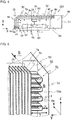
- Fig. 4 is an explanatory view for illustrating an A-A cross section of Fig. 2 .
- the x-direction, y-direction, and z-direction described below correspond to the x-direction, y-direction, and z-direction illustrated in the drawings, respectively.
- the outdoor unit 100 has, for example, a substantially rectangular parallelepiped casing. That is, as illustrated in Fig. 2 , the outdoor unit 100 includes a front panel 51 forming a front surface side of the casing of the outdoor unit 100, a side panel 52 forming a side surface side of the casing, and a top panel 53 forming a top surface side of the casing. Moreover, as illustrated in Fig. 4 , the outdoor unit 100 includes a rear panel 55 configured to cover a rear surface side and a side surface side, which is a side opposed to the side panel 52, of the outdoor unit 100. The rear panel 55 has an air inlet 59 for taking air into the outdoor unit 100.
- the front panel 51 of the outdoor unit 100 has an air outlet 62 for discharging air to an outside.
- An outer side of the air outlet 62 is covered with a fan guard 61.
- the configuration of the casing of the outdoor unit 100 is not limited to the configuration described above, and may suitably be changed.
- the panels such as the front panel 51 forming the casing of the outdoor unit 100 may be integrally formed in combination. Moreover, each panel may further be formed of a plurality of separate panels.
- a space inside the outdoor unit 100 is partitioned by a separator 64 into a machine chamber 80 and an air passage 63.
- the machine chamber 80 accommodates the compressor 11, the pressure reducing device 12, and the flow switching device 14.
- the outdoor heat exchanger 90 is arranged on an upstream side, and the outdoor unit fan 60 is arranged on a downstream side.
- the outdoor heat exchanger 90 has one end arranged in the machine chamber 80.
- joint portions 6e are provided at the one end of the outdoor heat exchanger 90 arranged in the machine chamber 80.
- the joint portions 6e are connected to one ends of heat transfer tubes 1 of the outdoor heat exchanger 90.
- the outdoor unit fan 60 installed in the air passage 63 is configured to suck air outside the outdoor unit 100 into the outdoor unit 100 through the air inlet 59 and blow out the air through the air outlet 62.
- the outdoor heat exchanger 90 has an L shape as seen from the top surface side, and is arranged so as to extend along the air inlet 59 formed in the rear panel 55. That is, the outdoor heat exchanger 90 is arranged over an entire region of the air passage 63 so as to block a flow of air from the air inlet 59 to the air outlet 62.
- the outdoor heat exchanger 90 is bent into the L shape.
- the outdoor heat exchanger 90 may have, for example, a rectangular shape having one open side, that is, a substantially U shape having two or more bent parts.
- the outdoor heat exchanger 90 includes two heat exchange portions.
- the heat exchange portions include an upstream-side heat exchange portion 91 arranged on the upstream side in the air passage 63 and a downstream-side heat exchange portion 92 arranged on the downstream side in the air passage 63.
- a plurality of fins 2 are mounted so as to be arrayed at predetermined intervals along a refrigerant flow passage of the heat transfer tubes 1.
- the upstream-side heat exchange portion 91 and the downstream-side heat exchange portion 92 are arrayed in the air flow direction in the air passage 63 so that respective fin installation portions 7b at which the fins 2 are arrayed overlap each other.
- a base panel 56 is arranged at a lower portion of the outdoor unit 100, and forms a bottom surface side of the casing of the outdoor unit 100.
- the base panel 56 is configured to support, for example, the outdoor heat exchanger 90, the outdoor unit fan 60, and the compressor 11, the pressure reducing device 12, and the flow switching device 14 which are accommodated in the machine chamber 80.
- the outdoor heat exchanger 90 includes the two heat exchange portions.
- the two heat exchange portions include the upstream-side heat exchange portion 91 arranged on the upstream side in the air passage 63 and the downstream-side heat exchange portion 92 arranged on the downstream side in the air passage 63.
- the outdoor heat exchanger 90 includes two rows of heat exchange portions.
- the number of rows of the heat exchange portions is not limited to two, and three or more rows of heat exchange portions may be arrayed from the upstream side to the downstream side in the air passage 63.
- Fig. 5 is a perspective view for illustrating an end portion of the outdoor heat exchanger 90 illustrated in Fig. 2 to Fig. 4 on a hairpin portion 6a side.
- the plurality of heat transfer tubes 1 are arrayed in the z-direction, and the fins 2 are mounted so as to be orthogonal to the plurality of heat transfer tubes 1.
- the heat transfer tubes 1 are each bent into an L shape as seen from the top surface side of the outdoor unit 100.
- the plurality of fins 2 are arrayed in a direction along the refrigerant flow passage of the heat transfer tubes 1 bent into the L shape, and the plurality of fins 2 are mounted at predetermined intervals.
- the heat transfer tubes 1 forming the upstream-side heat exchange portion 91 and the downstream-side heat exchange portion 92 extend from the joint portions 6e being the end portions on the machine chamber 80 side toward other end portions, are bent downward and folded back at the other end portions, and return to the machine chamber 80. At the other end portion, the heat transfer tubes 1 have no fin 2 mounted thereto and are exposed, and are bent into the U shape. A part of the heat exchanger pipe 1 exposed at the other end portion is particularly referred to as "hairpin portion 6a".
- pipe portions 6f extending between the joint portion 6e and the hairpin portion 6a are arrayed in the up-and-down direction of the outdoor unit 100, and are parallel to each other.
- the upper and lower pipe portions 6f pass along the same path.
- the pipe portions 6f are each a part indicated by the dotted line in Fig. 4 , and the fins 2 are mounted at this part to be the fin installation portion 7b.
- the joint portions 6e are provided on the end portion side of the heat transfer tubes 1 opposite to the side on which the hairpin portions 6a are connected.
- the inside of the heat transfer tube 1 is a flow passage for refrigerant, and the refrigerant flows in from the joint portion 6e side, turns back at the hairpin portion 6a, and returns to the joint portion 6e side.
- the refrigerant flows into the heat transfer tube 1 through one of two end portions of the heat transfer tube 1 arranged on the joint portion 6e side, passes through one pipe portion 6f, turns back at the hairpin portion 6a, passes through the other pipe portion 6f, returns to the join portion 6e side, and flows out from the outdoor heat exchanger 90.
- the heat exchange medium which flows inside the heat transfer tube 1 fluid such as water, refrigerant, or brine is used.
- a flat tube is used as the heat transfer tube 1.
- the heat transfer tube 1 has a sectional shape of a rectangle with rounded corners, and the rectangle has a predetermined aspect ratio.
- the heat transfer tube 1 is formed of a hollow metal pipe, which is made of metal having favorable thermal conductivity such as aluminum or copper.
- the flat tube is used as the heat transfer tube 1.
- the present invention is not limited to this, and a pipe having a sectional shape of a circle may be used.
- the fin 2 is formed into a thin plate shape, and has a plurality of cutout portions 3 for receiving the heat transfer tubes 1 inserted thereinto.
- the plurality of cutout portions 3 are formed at a constant pitch along a longitudinal direction of the fin 2.
- the fin 2 has a sectional shape of a rectangle with rounded corners. That is, the cutout portion 3 is formed in conformity with the sectional shape of the heat transfer tube 1 so that the heat transfer tube 1 can be inserted into the cutout portion 3.
- the fin 2 receives the heat transfer tubes 1 inserted into the cutout portions 3, and is fixed to the heat transfer tubes 1 at the cutout portions 3 by, for example, brazing.
- the plurality of fins 2 are mounted so as to be arrayed at predetermined intervals along a longitudinal direction of the heat transfer tube 1, that is, along an extending direction of the refrigerant flow passage inside the heat transfer tube 1. However, the fin 2 is not mounted in a periphery of the hairpin portions 6a of the heat transfer tubes 1, and the heat transfer tubes 1 are exposed.
- Fig. 6 is an explanatory view for illustrating a B-B cross section of Fig. 5 .
- the cutout portion 3 of the fin 2 extends from one end portion to an other end portion in a direction orthogonal to the longitudinal direction of the fin 2.
- the cutout portion 3 is opened on the upstream side in the air passage 63.
- illustration of the cutout portions 3 is omitted.
- the outdoor heat exchanger 90 is arranged in the air passage 63 inside the outdoor unit 100, and is arranged so as to extend along the air inlet 59.
- the fin installation portions 7b of the upstream-side heat exchange portion 91 and the downstream-side heat exchange portion 92 are arranged so as to cover an entire region of the air inlet 59. With such arrangement, the air having flowed in through the air inlet 59 passes through the plurality of fins 2, thereby promoting heat exchange with the refrigerant flowing in the heat transfer tubes 1.
- the upstream-side heat exchange portion 91 and the downstream-side heat exchange portion 92 are arranged so that ends of the hairpin portions 6a are aligned.
- the upstream-side heat exchange portion 91 and the downstream-side heat exchange portion 92 are arranged so that positions of ends of the hairpin portions 6a in a direction along the refrigerant flow passage of the heat transfer tubes 1 are aligned.
- the hairpin portions 6a are arranged in the vicinity of the front panel 51, and the ends of the hairpin portions 6a are arranged apart from the front panel 51 with a predetermined gap "p".
- fin end portions 7a which are end portions of the portions at which the fins 2 of the upstream-side heat exchange portion 91 and the downstream-side heat exchange portion 92 are arranged, are also arranged so that positions thereof in the longitudinal direction of the heat transfer tubes 1 are aligned.
- the fin end portions 7a are arranged apart from the front panel 51 by a predetermined distance "q".
- the air passage blocking object 50 is arranged in the vicinity of the hairpin portions 6a of the outdoor heat exchanger 90.
- the air passage blocking object 50 is installed on a wall surface 51a on an inner side of the front panel 51, and is provided upright on the wall surface 51a on the inner side of the front panel 51 so as to block the flow of air in the air passage 63.
- the air passage blocking object 50 is, for example, provided integrally with the wall surface 51a.
- the air passage blocking object 50 may be fixed to the wall surface 51a by a method such as fastening with screws.
- Fig. 7 is an enlarged view for illustrating a periphery of the hairpin portions 6a of the outdoor heat exchanger 90 in Fig. 4 .
- the air passage blocking object 50 is arranged on the downstream side of the hairpin portions 6a and the fin end portion 7a of the downstream-side heat exchange portion 92.
- the air passage blocking object 50 extends in a direction from the wall surface 51a on the inner side of the front panel 51 to the position at which the fin end portion 7a of the downstream-side heat exchange portion 92 is installed.
- a height H of the air passage blocking object 50 from the wall surface 51a on the inner side of the front panel 51 is set equal to or larger than the distance "q" from the wall surface 51a on the inner side of the front panel 51 to the fin end portion 7a.
- the air passage blocking object 50 has a sectional shape illustrated in Fig.
- the air passage blocking object 50 is installed so as to cover the entirety of the plurality of hairpin portions 6a of the downstream-side heat exchange portion 92 from the downstream side in the air passage. With such a configuration, the air flowing in through the air inlet 59 passes on the fin installation portion 7b side in the outdoor heat exchanger 90. The downstream side of the hairpin portions 6a in the air passage 63 is blocked, and hence the air is prevented from flowing in.
- the air passage blocking object 50 is not limited to the case of being installed so as to cover the entirety of the hairpin portions 6a, and may have a configuration in which a cutout portion is partially formed so that part of the hairpin portions 6a is not covered.
- the cutout portion may be closed with a separate component which is present in the vicinity of the outdoor heat exchanger 90.
- a distal end portion 50a of the air passage blocking object 50 extending toward the inner side of the air passage 63 from the wall surface 51a may be held in abutment against the fin installation portion 7b.
- An interference member such as a rubber sheet may be interposed at a portion at which the distal end portion 50a and the fin installation portion 7b are held in abutment against each other.
- Fig. 8 and Fig. 9 are enlarged views for illustrating a hairpin portion 6a of an outdoor heat exchanger 90 of an outdoor unit 100a for an air-conditioning apparatus in a comparative example.
- the outdoor unit 100a for an air-conditioning apparatus in the comparative example is different from the outdoor unit 100 in that the air passage blocking object 50 is not provided.
- Other configurations are the same in the outdoor unit 100 and the outdoor unit 100a. Thus, in the following description, common portions are described with the same reference symbols.
- the outdoor heat exchanger 90 When the air-conditioning apparatus performs the heating operation, the outdoor heat exchanger 90 operates as an evaporator.
- dew condensation water is generated in the outdoor heat exchanger 90.
- the dew condensation water is frozen, and frost adheres to the fins 2 or the heat transfer tubes 1.
- frost adheres to the outdoor heat exchanger 90 the fins 2 are clogged and cause the air to be less likely to pass therethrough, with the result that heat exchange efficiency is degraded.
- the efficiency of the refrigeration cycle is also degraded, with the result that the air-conditioning performance of the air-conditioning apparatus is degraded. Therefore, in the air-conditioning apparatus, the heating operation and the defrosting operation are alternately repeated to melt the frost adhering to the outdoor heat exchanger 90, thereby performing control of preventing degradation in heat exchange efficiency.
- the air passage blocking object 50 is not installed. Therefore, the air having flowed in through the air inlet 59 is liable to pass through the hairpin portions 6a of the outdoor heat exchanger 90.
- the fins 2 are not provided at the hairpin portions 6a, but the heat transfer tubes 1 are exposed to the air having flowed in through the air inlet 59, with the result that frost is formed.
- the frost adhering to the hairpin portion 6a is melted by the defrosting operation to be formed into dew condensation water. As illustrated in Fig. 8 and Fig.
- dew condensation water 9 part of the dew condensation water remains adhering to a horizontal portion 6b on the upper side of the hairpin portion 6a, and flowing dew condensation water also flows along an arc portion 6c of the hairpin portion 6a in the direction indicated by the arrows in Fig. 8 and Fig. 9 , and flows to a horizontal portion 6d on the lower side.
- dew condensation waters 9a, 9b, 9c, and 9d adhere to the horizontal portions 6b and 6d of the hairpin portion 6a.
- the melted frost or dew condensation water formed by the ice further adheres to the ice and is frozen during the heating operation.
- the ice is gradually increased in size, for example, as indicated by an ice 8a in Fig. 9 , and is further combined with ice formed by freezing of the dew condensation water 9d accumulated on the horizontal portion 6d on the lower side as indicated by an ice 8b.
- the ice formed on the hairpin portion 6a in the manner described above grows so as to connect the horizontal portion 6b on the upper side and the horizontal portion 6d on the lower side to each other, and presses the horizontal portion 6b and the horizontal portion 6d in the up-and-down direction. As a result, the heat transfer tube 1 is broken from the portion pressed by ice.
- the outdoor unit 100a in the comparative example does not include the air passage blocking object 50, and hence the hairpin portion 6a is frozen, with the result that the heat transfer tube 1 is broken.
- Embodiment 1 and the comparative example use of the flat tube as the heat transfer tube 1 causes the dew condensation water to be liable to remain on the heat transfer tube 1. Therefore, when the flat tube is to be used for the outdoor heat exchanger 90, there is higher necessity to take a countermeasure to prevent exposure of the hairpin portion 6a to the air as compared to the case of using a pipe having a circular cross section as the heat transfer tube 1.
- the outdoor unit 100 according to Embodiment 1 has a configuration in which, as illustrated in Fig. 6 , the air passage blocking object 50 causes the air to be less likely to pass through the hairpin portion 6a, thereby being capable of preventing freezing unlike the hairpin portion 6a in the comparative example. Therefore, the breakage of the heat transfer tube 1 can be prevented.
- the air passage blocking object 50 is installed so as to cover only the hairpin portion 6a, that is, block the air passage 63 in a range of from the fin end portion 7a to the wall surface 51a on the inner side of the front panel 51. Therefore, the air passing through the fins 2 is not blocked, and hence the performance of the outdoor heat exchanger 90 is not degraded.
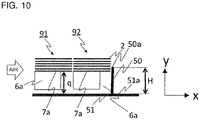
- Fig. 10 is an illustration of the air passage blocking object 50 illustrated in Fig. 7 , which is changed in height.
- the height H of the air passage blocking object 50 from the wall surface 51a on the inner side of the front panel 51 is set equal to or larger than the distance "q" from the wall surface 51a on the inner side of the front panel 51 to the fin end portion 7a.
- the height H is set larger than the distance "q" so that the air passage blocking object 50 and the fins 2 of the downstream-side heat exchange portion 92 overlap each other, inflow of the air to the hairpin portions 6a can be suppressed even when there is dimensional variation given at the time of manufacturing.
- the air passage blocking object 50 is configured to block airflow in a space in the air passage 63 which is defined between the wall surface 51a forming the air passage 63 on the side on which the hairpin portions 6a are arranged, and the end surfaces of the fins 2 on the side on which the hairpin portions 6a are arranged.
- the outdoor unit 100 for an air-conditioning apparatus is capable of suppressing inflow of air outside the outdoor unit 100 into the hairpin portions 6a of the outdoor heat exchanger 90.
- the air is prevented from flowing into the hairpin portions 6a.
- occurrence of dew condensation and frost formation on the hairpin portions 6a can be prevented, and damage on the hairpin portions 6a due to freezing can be prevented.
- the air passage blocking object 50 is provided upright on the wall surface 51a defining the air passage 63 on the side on which the hairpin portions 6a are arranged.
- the height of the air passage blocking object 50 from the wall surface 51a is set equal to or larger than the distance "q" from the fin end portion 7a, which is closest from the wall surface 51a, to the wall surface 51a.
- the outdoor unit 100 for an air-conditioning apparatus is capable of preventing formation of a gap between the fin end portion 7a and the air passage blocking object 50, thereby being capable of more reliably preventing inflow of air outside the outdoor unit 100 into the hairpin portions 6a of the outdoor heat exchanger 90.
- the heat transfer tubes 1 are inserted into the cutout portions 3 formed in the fins 2.
- the cutout portions 3 are opened at one end of the fin 2 in the direction orthogonal to the longitudinal direction of the fin 2, and extend from the one end toward an other end of the fin 2.
- the other end of the fin 2 is oriented toward a side on which the air passage blocking object 50 is arranged.
- the edge portions 2b of the fin 2 are arranged between the air passage blocking object 50 and the heat transfer tubes 1, and hence the air passage blocking object 50 and the heat transfer tubes 1 are prevented from being brought into direct contact with each other. With this, even when the outdoor unit 100 is to be assembled, the air passage blocking object 50 and the heat transfer tubes 1 are prevented from being brought into contact with each other, thereby being capable of preventing damage on the heat transfer tubes 1.
- the air passage blocking object 50 has a distal end portion held in abutment against the fin 2.
- the air passage blocking object 50 is provided at a position on the downstream side in the flow of air with respect to the outdoor heat exchanger 90.
- the outdoor unit 100 for an air-conditioning apparatus is capable of attaining an effect similar to that of the above-mentioned item (1).
- the outdoor unit 100 for an air-conditioning apparatus has a feature in that the heat transfer tube 1 has an elongate sectional shape, and is arranged so that a longitudinal axis of the elongate shape is horizontally oriented.
- a flat tube which is advantageous for heat exchange but is less likely to remove the dew condensation water therefrom can be used as the heat transfer tube 1. Therefore, dew condensation and frost formation are prevented from occurring on the flat tube which is less likely to remove the dew condensation water therefrom, thereby being capable of preventing damage on the hairpin portion 6a due to freezing.
- the upstream-side heat exchange portion 91 and the downstream-side heat exchange portion 92 each having the L shape are arrayed on the upstream side and the downstream side in the air passage 63. Therefore, when the upstream-side heat exchange portion 91 and the downstream-side heat exchange portion 92 have a configuration in which ends of the respective hairpin portions 6a are aligned, the lengths of the heat transfer tubes 1 differ. When the outdoor heat exchanger 90 has such a configuration, the number of components required for manufacturing increases. Therefore, the heat transfer tubes 1 having the same length for both the upstream-side heat exchange portion 91 and the downstream-side heat exchange portion 92 can also be used.
- Figs. 11 are side views for illustrating the hairpin portions 6a of the outdoor heat exchanger 90 of the outdoor unit 100 according to Embodiment 1 of the present invention.
- Fig. 11(a) is an explanatory view for illustrating the hairpin portions 6a in a case in which the heat transfer tubes 1 of the outdoor heat exchanger 90 have the same length.
- Fig. 11(b) is an explanatory view for illustrating the hairpin portions 6a in a case in which the heat transfer tubes 1 of the outdoor heat exchanger 90 according to Embodiment 1 of the present invention have different lengths for the upstream-side heat exchange portion 91 and the downstream-side heat exchange portion 92.
- Figs. 11 are side views for illustrating the hairpin portions 6a of the outdoor heat exchanger 90 of the outdoor unit 100 according to Embodiment 1 of the present invention.
- Fig. 11(a) is an explanatory view for illustrating the hairpin portions 6a in a case in which the heat transfer tubes 1 of the outdoor heat exchanger 90 according to
- the heat transfer tubes 1 of the upstream-side heat exchange portion 91 are indicated by solid lines, and the heat transfer tubes 1 of the downstream-side heat exchange portion 92 are indicated by broken lines. Moreover, for easy understanding of the illustration, the heat transfer tubes 1 of the upstream-side heat exchange portion 91 and the heat transfer tubes 1 of the downstream-side heat exchange portion 92 are illustrated with displacement in the up-and-down direction.
- the outdoor heat exchanger 90 has such a configuration that the heat transfer tubes 1 have the same length for the upstream-side heat exchange portion 91 and the downstream-side heat exchange portion 92 and that the fin end portions 7a are aligned
- the hairpin portions 6a of the upstream-side heat exchange portion 91 which are bent into the L shape and provided at a position on an outer side, have a small length.
- the ends of the hairpin portions 6a can be aligned while the fin end portions 7a are aligned.
- the outdoor heat exchanger 90 it is advantageous for the outdoor heat exchanger 90 to have a configuration in which the length of the heat transfer tubes 1 of the upstream-side heat exchange portion 91 is set larger than the length of the heat transfer tubes 1 of the downstream-side heat exchange portion 92 and in which the ends of the hairpin portions 6a are aligned.
- an outdoor unit 200 for an air-conditioning apparatus according to Embodiment 2 of the present invention, a position of the air passage blocking object 50 is changed from that of the outdoor unit 100 according to Embodiment 1.
- the outdoor unit 200 according to Embodiment 2 changes from Embodiment 1 are mainly described.
- components of the outdoor unit 200 according to Embodiment 2 components having the same functions in the drawings are denoted by the same reference symbols as those of the drawings used for description of Embodiment 1.
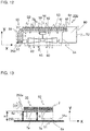
- Fig. 12 is an explanatory view for illustrating a horizontal cross section of the outdoor unit 200 for an air-conditioning apparatus according to Embodiment 2 of the present invention.
- Fig. 13 is an enlarged view for illustrating a periphery of the hairpin portions 6a of the outdoor heat exchanger 90 in Fig. 12 .
- the cross section illustrated in Fig. 12 corresponds to the A-A cross section of Embodiment 1 in Fig. 2 .
- an air passage blocking object 250 is arranged on an upstream side of the hairpin portions 6a of the upstream-side heat exchange portion 91.
- the air passage blocking object 250 extends from the front panel 51 toward the inner side of the air passage 63 in parallel with the longitudinal direction of the heat transfer tube 1, that is, the flow direction of the refrigerant flowing inside the heat transfer tube 1.
- a height H of the air passage blocking object 250 from the wall surface 51a on the inner side of the front panel 51 is set equal to or larger than the distance "q" from the front panel 51 to the fin end portion 7a.
- the air passage blocking object 250 is provided upright on the wall surface 51a on the inner side of the front panel 51, but the present invention is not limited to this configuration.
- the air passage blocking object 250 may be formed integrally with the rear panel 55. That is, it is only required that the air passage blocking object 250 block the upstream side of the hairpin portions 6a of the upstream-side heat exchange portion 91 and suppress inflow of the air to a space from the front panel 51 to the fin end portions 7a.
- the cutout portions 3 of the fins 2 of the upstream-side heat exchange portion 91 are formed so as to be opened on the downstream side.
- the heat transfer tubes 1 of the upstream-side heat exchange portion 91 are arranged close to the downstream side.
- the heat transfer tube 1 is arranged apart from the air passage blocking object 250 by a certain distance, thereby being capable of preventing damage due to contact between the heat transfer tubes 1 and the air passage blocking object 250.
- the air passage blocking object 250 is provided at a position on an upstream side in the flow of the air with respect to the outdoor heat exchanger 90.
- the outdoor unit 200 for an air-conditioning apparatus according to Embodiment 2 is capable of preventing inflow of the air to the upstream-side heat exchanger portion 91 at which dew condensation and frost formation are more liable to occur. Therefore, the effect of suppressing freezing is higher as compared to the outdoor unit 100 according to Embodiment 1. Further, the air passage blocking object 250 of the outdoor unit 200 blocks the upstream side in the air passage 63, thereby being capable of preventing entry of, for example, dust, snow, or water flying from the outside of the outdoor unit 200.
- the outdoor unit 200 is capable of not only suppressing the inflow of the air to the hairpin portions 6a but also preventing entry of other flying objects. Therefore, the effect of preventing damage on the hairpin portions 6a is higher as compared to the outdoor unit 100 according to Embodiment 1.
- the air passage blocking object 250 when the air passage blocking object 250 is arranged on the upstream side of the upstream-side heat exchange portion 91, the air having passed through the fins 2 of the upstream-side heat exchange portion 91 may flow into the hairpin portions 6a of the downstream-side heat exchange portion 92 through a space between the upstream-side heat exchange portion 91 and the downstream-side heat exchange portion 92.
- the air having passed through the fins 2 of the upstream-side heat exchange portion 91 is dehumidified through heat exchange in the upstream-side heat exchange portion 91. Therefore, even when the air flows into the hairpin portions 6a, frost formation is less liable to occur.
- the effect of suppressing inflow of the air into the hairpin portions 6a can be further enhanced by holding a distal end portion 250a of the air passage blocking object 250 in abutment against the fin 2.
Landscapes
- Engineering & Computer Science (AREA)
- Mechanical Engineering (AREA)
- General Engineering & Computer Science (AREA)
- Chemical & Material Sciences (AREA)
- Combustion & Propulsion (AREA)
- Physics & Mathematics (AREA)
- Thermal Sciences (AREA)
- Other Air-Conditioning Systems (AREA)
- Heat-Exchange Devices With Radiators And Conduit Assemblies (AREA)
Abstract
Description
- The present invention relates to an outdoor unit for an air-conditioning apparatus including a heat exchanger.
- There has been known an outdoor unit for an air-conditioning apparatus including a fin-tube heat exchanger mounted thereto. One such heat exchanger includes a flat tube having a sectional shape of a rectangle with rounded corners. The heat exchanger using the flat tube is herein referred to as "flat-tube heat exchanger".
- There has been known a flat-tube heat exchanger having the following configuration. That is, U-shaped cutouts are formed in each of fins so as to extend in a width direction from one end of the fin in the width direction, and flat tubes are fitted to the cutouts. In the flat-tube heat exchanger, heat transfer tubes are each formed by bending one flat tube into a U shape. The flat-tube heat exchanger includes a plurality of heat exchange portions. In each of the heat exchange portions, a plurality of flat tubes are arrayed so that longitudinal directions of the elongate shapes are aligned, and the fins are connected to the flat tubes so as to be arrayed with a plurality of predetermined gaps. When seen in a direction along a longitudinal direction of the fins, the flat-tube heat exchanger is typically bent into an L shape or a substantially U shape.
- When heat exchangers using flat tubes having the same length are arrayed in a plurality of rows and bent into the L shape, a heat exchanger provided at a position on an outer side of the L-shaped bent part has a bend radius that is different from a bend radius of a heat exchanger provided at a position on an inner side of the L-shaped bent part have different. Therefore, the heat exchanger provided on the inner side of the bent part and the heat exchanger provided on the outer side of the bent part are not aligned at positions of U-shaped bent portions being one end portions of the heat exchangers (hereinafter also referred to as "hairpin portion") or at positions of header connection portions being other end portions. In a heat exchanger of
Patent Literature 1, a plurality of rows of heat exchange portions are arrayed with hairpin portions being aligned, the hairpin portions being one end portions. - Patent Literature 1:
JP 2014-228236 A - In the related-art flat-tube heat exchanger, when the arrayed hairpin portions of the flat tubes are not aligned, the hairpin portions of the upstream-side heat exchanger provided at the position on the outer side of the L-shaped bent part and fins of the downstream-side heat exchanger provided at the position on the inner side of the L-shaped bent part are arranged in an air passage to be overlapped. When this flat-tube heat exchanger is used as an evaporator in a refrigeration cycle of an air-conditioning apparatus, air passes also through the hairpin portions of the upstream-side heat exchanger overlapping with the fins of the downstream-side heat exchanger, with the result that dew condensation occurs on the hairpin portions of the flat tubes. When a heating operation is performed under a low-temperature outdoor air condition, frost is formed on the hairpin portions of the flat tubes.
- When the heating operation is performed under the low-temperature outdoor air condition, the air-conditioning apparatus alternately repeats the heating operation and a defrosting operation. The flat tubes are arranged so that one straight portion of the U-shaped portion is positioned on an upper side and an other straight portion is positioned on a lower side, and moisture content adhering to the upper straight portion of the hairpin portion flows to the lower straight portion along an arc-shaped portion of the U-shaped hairpin portion. Moreover, wide flat portions of the flat tube in a sectional shape are oriented in the up-and-down direction, and hence the moisture content having flowed to the lower straight portion of the hairpin portion is less likely to flow down from the flat portion, with the result that the moisture content is liable to accumulate. When frost is formed on the hairpin portion of the flat tube, the frost is melted by the defrosting operation. However, when the melted water does not completely flow down from the flat tube and remains thereon, the dew condensation water is frozen during the heating operation, and ice is formed.
- When part of the ice is not completely melted during the defrosting operation, the moisture content accumulates on the ice, and is frozen during the heating operation. As the heating operation and the defrosting operation are repeated, the ice gradually grows. The heat exchanger is arranged so that the one straight portion of the U-shaped portion of the hairpin portion is positioned on the upper side and the other straight portion is positioned on the lower side. The grown ice further grows so as to connect the upper and lower straight portions to each other. The grown ice may press the flat tube to cause breakage of the pipe.
- Meanwhile, according to the disclosure of
Patent Literature 1, in the heat exchanger, the plurality of rows of the heat exchange portions are arranged so that respective hairpin portions of the heat exchange portions are aligned. However, fin portions of the respective heat exchange portions have a small space between the fins, and air flows through the fin portions less easily than through the hairpin portions. Therefore, air having sucked into the outdoor unit flows also to the hairpin portions which allow air to easily pass therethrough, with the result that frost is formed similarly to the related-art flat-tube heat exchanger described above. Thus, the moisture content adhering to the flat tubes may be frozen to form ice, and the growth of the ice may cause breakage of the tube. - The present invention has been made to solve the problems described above, and has an object to prevent breakage of a heat transfer tube caused by ice which adheres to a hairpin portion of a heat exchanger and grows thereat.
- According to one embodiment of the present invention, there is provided an outdoor unit for an air-conditioning apparatus, including: an air passage defined inside a casing; an outdoor heat exchanger installed in the air passage; an outdoor unit fan configured to introduce air into the outdoor heat exchanger; and an air passage blocking object configured to block a flow of part of the air in the air passage, wherein the outdoor heat exchanger includes a heat transfer tube configured to allow refrigerant to pass therein, and a fin connected to the heat transfer tube, wherein the heat transfer tube includes a hairpin portion, which is a portion of the heat transfer tube bent and folded back and to which no fin is connected, and wherein the air passage blocking object is configured to cover the hairpin portion.
- With the outdoor unit for an air-conditioning apparatus according to one embodiment of the present invention, the configuration described above blocks the flow of air to the hairpin portion, thereby being capable of suppressing frost formation and freezing at the hairpin portion. Moreover, the air passage blocking object does not block the fin portion of the heat exchanger, and hence heat exchange performance is not degraded.
-
-
Fig. 1 is a circuit diagram for illustrating a refrigerant circuit including an outdoor unit for an air-conditioning apparatus according toEmbodiment 1 of the present invention. -
Fig. 2 is a perspective view for illustrating the outdoor unit for an air-conditioning apparatus according toEmbodiment 1 of the present invention. -
Fig. 3 is a perspective view for illustrating a state in which an exterior cover component of the outdoor unit illustrated inFig. 2 is removed. -
Fig. 4 is an explanatory view for illustrating an A-A cross section ofFig. 2 . -
Fig. 5 is a perspective view for illustrating an end portion of an outdoor heat exchanger illustrated inFig. 2 to Fig. 4 on a hairpin portion side. -
Fig. 6 is an explanatory view for illustrating a B-B cross section ofFig. 5 . -
Fig. 7 is an enlarged view for illustrating a periphery of the hairpin portions of the outdoor heat exchanger inFig. 4 . -
Fig. 8 is an enlarged view for illustrating a hairpin portion of an outdoor heat exchanger in a comparative example. -
Fig. 9 is an enlarged view for illustrating the hairpin portion of the outdoor heat exchanger in the comparative example. -
Fig. 10 is an illustration of an air passage blocking object illustrated inFig. 7 , which is changed in height. -
Figs. 11 are side views for illustrating the hairpin portions of the outdoor heat exchanger of the outdoor unit according to Embodiment 1 of the present invention. -
Fig. 12 is an explanatory view for illustrating a horizontal cross section of an outdoor unit for an air-conditioning apparatus according toEmbodiment 2 of the present invention. -
Fig. 13 is an enlarged view for illustrating a periphery of the hairpin portions of the outdoor heat exchanger inFig. 12 . -
Fig. 1 is a circuit diagram for illustrating arefrigerant circuit 10 including anoutdoor unit 100 for an air-conditioning apparatus according toEmbodiment 1 of the present invention. Description is made ofEmbodiment 1 with reference to the drawings. - An air-conditioning apparatus in
Embodiment 1 includes therefrigerant circuit 10 illustrated inFig. 1 . Therefrigerant circuit 10 includes a compressor 11, a flow switching device 14, anoutdoor heat exchanger 90, apressure reducing device 12, and anindoor heat exchanger 13, which are sequentially connected by refrigerant pipes to form a refrigeration cycle circuit. In therefrigerant circuit 10, the portion surrounded by the dotted lines represents theoutdoor unit 100. Theoutdoor unit 100 includes the compressor 11, the flow switching device 14, theoutdoor heat exchanger 90, and thepressure reducing device 12, and anoutdoor unit fan 60 configured to send air to theoutdoor heat exchanger 90 is installed in the vicinity of theoutdoor heat exchanger 90. Moreover, in therefrigerant circuit 10, the portion surrounded by the two-dot chain lines represents anindoor unit 101. Theindoor unit 101 includes theindoor heat exchanger 13, and anindoor unit fan 15 configured to send indoor air to theindoor heat exchanger 13 is installed in the vicinity of theindoor heat exchanger 13. - The compressor 11 is configured to suck and compress refrigerant to bring the refrigerant into a high-temperature and high-pressure state, and is formed of, for example, a scroll-type compressor or a vane-type compressor. The flow switching device 14 is configured to switch between a heating flow passage and a cooling flow passage in accordance with an operation mode such as a cooling operation or a heating operation, and is formed of, for example, a four-way valve. During the heating operation, the flow switching device 14 connects a discharge side of the compressor 11 and the
indoor heat exchanger 13 to each other, and connects theoutdoor heat exchanger 90 and a suction side of the compressor 11 to each other. At this time, the refrigerant flows along the paths of the flow switching device 14 indicated by the solid lines in the refrigerant circuit diagram ofFig. 1 . Meanwhile, during the cooling operation, the flow switching device 14 connects the discharge side of the compressor 11 and theoutdoor heat exchanger 90 to each other, and connects theindoor heat exchanger 13 and the suction side of the compressor 11 to each other. At this time, the refrigerant flows along the paths of the flow switching device indicated by the broken lines in the refrigerant circuit diagram ofFig. 1 . Illustration is given of the example case in which the four-way valve is used as the flow switching device 14. However, the flow switching device 14 is not limited to the four-way valve, and may be formed of, for example, a combination of a plurality of two-way valves. - The
outdoor heat exchanger 90 is configured to exchange heat between refrigerant and outdoor air. Theoutdoor unit fan 60 installed in the vicinity of theoutdoor heat exchanger 90 is configured to send outdoor air to theoutdoor heat exchanger 90. - The
pressure reducing device 12 is provided between theindoor heat exchanger 13 and theoutdoor heat exchanger 90, and is configured to adjust a state of refrigerant by adjusting a flow rate. Thepressure reducing device 12 is formed of, for example, an expansion device or an open/close valve configured to switch on and off the flow of refrigerant by opening and closing. - Next, description is made of operation examples of a refrigeration cycle in
Embodiment 1. First, description is made of an operation example of therefrigerant circuit 10 in the case of the heating operation in which theoutdoor heat exchanger 90 operates as an evaporator. InFig. 1 , during the heating, the refrigerant flows in the direction of the arrows indicated by the solid lines inFig. 1 . Also in the flow switching device 14, the refrigerant flows along the paths indicated by the solid lines. The refrigerant is compressed into high-temperature and high-pressure gas refrigerant in the compressor 11. The high-temperature and high-pressure gas refrigerant having been discharged from the compressor 11 flows into theindoor heat exchanger 13 through the flow switching device 14. The high-temperature and high-pressure gas refrigerant having flowed into theindoor heat exchanger 13 rejects heat in theindoor heat exchanger 13 and is condensed from gas into liquid. The heat having been rejected in theindoor heat exchanger 13 heats air in an indoor space in which theindoor unit 101 is installed. The refrigerant having been condensed in theindoor heat exchanger 13 flows from theindoor heat exchanger 13 into thepressure reducing device 12 and is reduced in pressure to be brought into a two-phase gas-liquid state. The refrigerant having been reduced in pressure to be brought into the two-phase gas-liquid state flows into theoutdoor heat exchanger 90, is evaporated through removal of heat from the air sent into theoutdoor heat exchanger 90 by theoutdoor unit fan 60, and is sucked into the compressor 11 through the flow switching device 14. - Next, description is made of an operation example of the
refrigerant circuit 10 in the case of the cooling operation in which theoutdoor heat exchanger 90 operates as a condenser. During the cooling, the refrigerant flows in the direction of the arrows indicated by the broken lines inFig. 1 . Also in the flow switching device 14, the refrigerant flows along the paths indicated by the broken lines. The refrigerant is compressed into high-temperature and high-pressure gas refrigerant in the compressor 11. The high-temperature and high-pressure gas refrigerant having been discharged from the compressor 11 flows into theoutdoor heat exchanger 90 through the flow switching device 14. The high-temperature and high-pressure gas refrigerant having flowed into theoutdoor heat exchanger 90 exchanges heat with air sent from theoutdoor unit fan 60, rejects heat, and is condensed from gas into liquid. The refrigerant having been condensed in theoutdoor heat exchanger 90 flows from theoutdoor heat exchanger 90 into thepressure reducing device 12 and is reduced in pressure to be brought into a two-phase gas-liquid state. The refrigerant having been reduced in pressure to be brought into the two-phase gas-liquid state flows into theindoor heat exchanger 13, is evaporated through exchange of heat with the indoor air sent by theindoor unit fan 15, and is sucked into the compressor 11 through the flow switching device 14. -
Fig. 2 is a perspective view for illustrating theoutdoor unit 100 for an air-conditioning apparatus according toEmbodiment 1 of the present invention.Fig. 3 is a perspective view for illustrating a state in which an exterior cover component of theoutdoor unit 100 illustrated inFig. 2 is removed.Fig. 4 is an explanatory view for illustrating an A-A cross section ofFig. 2 . The x-direction, y-direction, and z-direction described below correspond to the x-direction, y-direction, and z-direction illustrated in the drawings, respectively. - The
outdoor unit 100 has, for example, a substantially rectangular parallelepiped casing. That is, as illustrated inFig. 2 , theoutdoor unit 100 includes afront panel 51 forming a front surface side of the casing of theoutdoor unit 100, aside panel 52 forming a side surface side of the casing, and atop panel 53 forming a top surface side of the casing. Moreover, as illustrated inFig. 4 , theoutdoor unit 100 includes arear panel 55 configured to cover a rear surface side and a side surface side, which is a side opposed to theside panel 52, of theoutdoor unit 100. Therear panel 55 has anair inlet 59 for taking air into theoutdoor unit 100. Thefront panel 51 of theoutdoor unit 100 has anair outlet 62 for discharging air to an outside. An outer side of theair outlet 62 is covered with afan guard 61. The configuration of the casing of theoutdoor unit 100 is not limited to the configuration described above, and may suitably be changed. The panels such as thefront panel 51 forming the casing of theoutdoor unit 100 may be integrally formed in combination. Moreover, each panel may further be formed of a plurality of separate panels. - A space inside the
outdoor unit 100 is partitioned by aseparator 64 into amachine chamber 80 and anair passage 63. Themachine chamber 80 accommodates the compressor 11, thepressure reducing device 12, and the flow switching device 14. In theair passage 63, theoutdoor heat exchanger 90 is arranged on an upstream side, and theoutdoor unit fan 60 is arranged on a downstream side. As illustrated inFig. 4 , theoutdoor heat exchanger 90 has one end arranged in themachine chamber 80. At the one end of theoutdoor heat exchanger 90 arranged in themachine chamber 80,joint portions 6e are provided. Thejoint portions 6e are connected to one ends ofheat transfer tubes 1 of theoutdoor heat exchanger 90. Although illustration is omitted inFig. 3 andFig. 4 , thejoint portions 6e of theoutdoor heat exchanger 90, which are arranged in themachine chamber 80, are connected to thepressure reducing device 12 and the flow switching device 14 by refrigerant pipes, and form therefrigerant circuit 10. - As indicated by the arrows in
Fig. 4 , theoutdoor unit fan 60 installed in theair passage 63 is configured to suck air outside theoutdoor unit 100 into theoutdoor unit 100 through theair inlet 59 and blow out the air through theair outlet 62. As illustrated inFig. 4 , theoutdoor heat exchanger 90 has an L shape as seen from the top surface side, and is arranged so as to extend along theair inlet 59 formed in therear panel 55. That is, theoutdoor heat exchanger 90 is arranged over an entire region of theair passage 63 so as to block a flow of air from theair inlet 59 to theair outlet 62. With such a configuration, the air having flowed into theair passage 63 inside theoutdoor unit 100 through theair inlet 59 passes through theoutdoor heat exchanger 90, exchanges heat with refrigerant flowing inside theoutdoor heat exchanger 90, and is blown out through theair outlet 62. InEmbodiment 1, theoutdoor heat exchanger 90 is bent into the L shape. However, theoutdoor heat exchanger 90 may have, for example, a rectangular shape having one open side, that is, a substantially U shape having two or more bent parts. - As illustrated in
Fig. 3 andFig. 4 , theoutdoor heat exchanger 90 includes two heat exchange portions. The heat exchange portions include an upstream-sideheat exchange portion 91 arranged on the upstream side in theair passage 63 and a downstream-sideheat exchange portion 92 arranged on the downstream side in theair passage 63. In each of the upstream-sideheat exchange portion 91 and the downstream-sideheat exchange portion 92, a plurality offins 2 are mounted so as to be arrayed at predetermined intervals along a refrigerant flow passage of theheat transfer tubes 1. The upstream-sideheat exchange portion 91 and the downstream-sideheat exchange portion 92 are arrayed in the air flow direction in theair passage 63 so that respectivefin installation portions 7b at which thefins 2 are arrayed overlap each other. - A
base panel 56 is arranged at a lower portion of theoutdoor unit 100, and forms a bottom surface side of the casing of theoutdoor unit 100. Thebase panel 56 is configured to support, for example, theoutdoor heat exchanger 90, theoutdoor unit fan 60, and the compressor 11, thepressure reducing device 12, and the flow switching device 14 which are accommodated in themachine chamber 80. - As described above, the
outdoor heat exchanger 90 includes the two heat exchange portions. The two heat exchange portions include the upstream-sideheat exchange portion 91 arranged on the upstream side in theair passage 63 and the downstream-sideheat exchange portion 92 arranged on the downstream side in theair passage 63. InEmbodiment 1, theoutdoor heat exchanger 90 includes two rows of heat exchange portions. However, the number of rows of the heat exchange portions is not limited to two, and three or more rows of heat exchange portions may be arrayed from the upstream side to the downstream side in theair passage 63. -
Fig. 5 is a perspective view for illustrating an end portion of theoutdoor heat exchanger 90 illustrated inFig. 2 to Fig. 4 on ahairpin portion 6a side. - As illustrated in
Fig. 5 , in each of the upstream-sideheat exchange portion 91 and the downstream-sideheat exchange portion 92, the plurality ofheat transfer tubes 1 are arrayed in the z-direction, and thefins 2 are mounted so as to be orthogonal to the plurality ofheat transfer tubes 1. Theheat transfer tubes 1 are each bent into an L shape as seen from the top surface side of theoutdoor unit 100. The plurality offins 2 are arrayed in a direction along the refrigerant flow passage of theheat transfer tubes 1 bent into the L shape, and the plurality offins 2 are mounted at predetermined intervals. Theheat transfer tubes 1 forming the upstream-sideheat exchange portion 91 and the downstream-sideheat exchange portion 92 extend from thejoint portions 6e being the end portions on themachine chamber 80 side toward other end portions, are bent downward and folded back at the other end portions, and return to themachine chamber 80. At the other end portion, theheat transfer tubes 1 have nofin 2 mounted thereto and are exposed, and are bent into the U shape. A part of theheat exchanger pipe 1 exposed at the other end portion is particularly referred to as "hairpin portion 6a". In oneheat transfer tube 1,pipe portions 6f extending between thejoint portion 6e and thehairpin portion 6a are arrayed in the up-and-down direction of theoutdoor unit 100, and are parallel to each other. As seen from the top surface of theoutdoor unit 100, the upper andlower pipe portions 6f pass along the same path. Thepipe portions 6f are each a part indicated by the dotted line inFig. 4 , and thefins 2 are mounted at this part to be thefin installation portion 7b. - As illustrated in
Fig. 4 , on the end portion side of theheat transfer tubes 1 opposite to the side on which thehairpin portions 6a are connected, there are provided thejoint portions 6e to which header pipes (not shown) are connected. The inside of theheat transfer tube 1 is a flow passage for refrigerant, and the refrigerant flows in from thejoint portion 6e side, turns back at thehairpin portion 6a, and returns to thejoint portion 6e side. In each of theheat transfer tubes 1 forming the upstream-sideheat exchange portion 91 and the downstream-sideheat exchange portion 92, the refrigerant flows into theheat transfer tube 1 through one of two end portions of theheat transfer tube 1 arranged on thejoint portion 6e side, passes through onepipe portion 6f, turns back at thehairpin portion 6a, passes through theother pipe portion 6f, returns to thejoin portion 6e side, and flows out from theoutdoor heat exchanger 90. As the heat exchange medium which flows inside theheat transfer tube 1, fluid such as water, refrigerant, or brine is used. - In
Embodiment 1, in particular, a flat tube is used as theheat transfer tube 1. Theheat transfer tube 1 has a sectional shape of a rectangle with rounded corners, and the rectangle has a predetermined aspect ratio. Moreover, theheat transfer tube 1 is formed of a hollow metal pipe, which is made of metal having favorable thermal conductivity such as aluminum or copper. InEmbodiment 1, the flat tube is used as theheat transfer tube 1. However, the present invention is not limited to this, and a pipe having a sectional shape of a circle may be used. - The
fin 2 is formed into a thin plate shape, and has a plurality ofcutout portions 3 for receiving theheat transfer tubes 1 inserted thereinto. The plurality ofcutout portions 3 are formed at a constant pitch along a longitudinal direction of thefin 2. As illustrated inFig. 3 , thefin 2 has a sectional shape of a rectangle with rounded corners. That is, thecutout portion 3 is formed in conformity with the sectional shape of theheat transfer tube 1 so that theheat transfer tube 1 can be inserted into thecutout portion 3. Thefin 2 receives theheat transfer tubes 1 inserted into thecutout portions 3, and is fixed to theheat transfer tubes 1 at thecutout portions 3 by, for example, brazing. The plurality offins 2 are mounted so as to be arrayed at predetermined intervals along a longitudinal direction of theheat transfer tube 1, that is, along an extending direction of the refrigerant flow passage inside theheat transfer tube 1. However, thefin 2 is not mounted in a periphery of thehairpin portions 6a of theheat transfer tubes 1, and theheat transfer tubes 1 are exposed. -
Fig. 6 is an explanatory view for illustrating a B-B cross section ofFig. 5 . Thecutout portion 3 of thefin 2 extends from one end portion to an other end portion in a direction orthogonal to the longitudinal direction of thefin 2. InEmbodiment 1, thecutout portion 3 is opened on the upstream side in theair passage 63. InFig. 5 , illustration of thecutout portions 3 is omitted. With such a configuration,edge portions 2b, which are connected portions of a plate remaining after cutting out thefin 2, allows theheat transfer tubes 1 to be arranged apart from an airpassage blocking object 50. Thus, when theoutdoor unit 100 is to be assembled, contact of the airpassage blocking object 50 with theheat transfer tubes 1 can be prevented, thereby being capable of preventing damage on thehairpin portions 6a. When the airpassage blocking object 50 is provided on the upstream side of theoutdoor heat exchanger 90, a similar effect can be attained by arranging thefin 2 so that the opening side of thecutout portions 3 is oriented toward the downstream side. - As illustrated in
Fig. 4 , theoutdoor heat exchanger 90 is arranged in theair passage 63 inside theoutdoor unit 100, and is arranged so as to extend along theair inlet 59. Thefin installation portions 7b of the upstream-sideheat exchange portion 91 and the downstream-sideheat exchange portion 92 are arranged so as to cover an entire region of theair inlet 59. With such arrangement, the air having flowed in through theair inlet 59 passes through the plurality offins 2, thereby promoting heat exchange with the refrigerant flowing in theheat transfer tubes 1. - In
Embodiment 1, the upstream-sideheat exchange portion 91 and the downstream-sideheat exchange portion 92 are arranged so that ends of thehairpin portions 6a are aligned. In other words, the upstream-sideheat exchange portion 91 and the downstream-sideheat exchange portion 92 are arranged so that positions of ends of thehairpin portions 6a in a direction along the refrigerant flow passage of theheat transfer tubes 1 are aligned. Thehairpin portions 6a are arranged in the vicinity of thefront panel 51, and the ends of thehairpin portions 6a are arranged apart from thefront panel 51 with a predetermined gap "p". Moreover,fin end portions 7a, which are end portions of the portions at which thefins 2 of the upstream-sideheat exchange portion 91 and the downstream-sideheat exchange portion 92 are arranged, are also arranged so that positions thereof in the longitudinal direction of theheat transfer tubes 1 are aligned. Thefin end portions 7a are arranged apart from thefront panel 51 by a predetermined distance "q". With the arrangement in which the positions of thefin end portions 7a of the upstream-sideheat exchange portion 91 and the downstream-sideheat exchange portion 92 are aligned, the air having passed through thefins 2 of the upstream-sideheat exchange portion 91 passes through thefins 2 of the downstream-side heat exchange portion. - In
Embodiment 1, the airpassage blocking object 50 is arranged in the vicinity of thehairpin portions 6a of theoutdoor heat exchanger 90. The airpassage blocking object 50 is installed on awall surface 51a on an inner side of thefront panel 51, and is provided upright on thewall surface 51a on the inner side of thefront panel 51 so as to block the flow of air in theair passage 63. The airpassage blocking object 50 is, for example, provided integrally with thewall surface 51a. Alternatively, the airpassage blocking object 50 may be fixed to thewall surface 51a by a method such as fastening with screws. -
Fig. 7 is an enlarged view for illustrating a periphery of thehairpin portions 6a of theoutdoor heat exchanger 90 inFig. 4 . - In
Embodiment 1, the airpassage blocking object 50 is arranged on the downstream side of thehairpin portions 6a and thefin end portion 7a of the downstream-sideheat exchange portion 92. The airpassage blocking object 50 extends in a direction from thewall surface 51a on the inner side of thefront panel 51 to the position at which thefin end portion 7a of the downstream-sideheat exchange portion 92 is installed. A height H of the airpassage blocking object 50 from thewall surface 51a on the inner side of thefront panel 51 is set equal to or larger than the distance "q" from thewall surface 51a on the inner side of thefront panel 51 to thefin end portion 7a. Moreover, the airpassage blocking object 50 has a sectional shape illustrated inFig. 6 and extends in the up-and-down direction of theoutdoor unit 100. The airpassage blocking object 50 is installed so as to cover the entirety of the plurality ofhairpin portions 6a of the downstream-sideheat exchange portion 92 from the downstream side in the air passage. With such a configuration, the air flowing in through theair inlet 59 passes on thefin installation portion 7b side in theoutdoor heat exchanger 90. The downstream side of thehairpin portions 6a in theair passage 63 is blocked, and hence the air is prevented from flowing in. The airpassage blocking object 50 is not limited to the case of being installed so as to cover the entirety of thehairpin portions 6a, and may have a configuration in which a cutout portion is partially formed so that part of thehairpin portions 6a is not covered. In this case, there is a risk of causing freezing due to inflow of the air into the part of thehairpin portions 6a. However, the freezing is limited to the part of thehairpin portions 6a, and hence the freezing can be prevented by, for example, control of the defrosting operation. Moreover, even when the cutout portion is formed at a part of the airpassage blocking object 50, for example, the cutout portion may be closed with a separate component which is present in the vicinity of theoutdoor heat exchanger 90. - Moreover, a
distal end portion 50a of the airpassage blocking object 50 extending toward the inner side of theair passage 63 from thewall surface 51a may be held in abutment against thefin installation portion 7b. An interference member such as a rubber sheet may be interposed at a portion at which thedistal end portion 50a and thefin installation portion 7b are held in abutment against each other. With such a configuration, a gap which allows the air to flow therethrough is not formed between thefin installation portion 7b and the airpassage blocking object 50, thereby being capable of improving the effect of suppressing the inflow of the air to thehairpin portions 6a. -
Fig. 8 and Fig. 9 are enlarged views for illustrating ahairpin portion 6a of anoutdoor heat exchanger 90 of anoutdoor unit 100a for an air-conditioning apparatus in a comparative example. Theoutdoor unit 100a for an air-conditioning apparatus in the comparative example is different from theoutdoor unit 100 in that the airpassage blocking object 50 is not provided. Other configurations are the same in theoutdoor unit 100 and theoutdoor unit 100a. Thus, in the following description, common portions are described with the same reference symbols. - When the air-conditioning apparatus performs the heating operation, the
outdoor heat exchanger 90 operates as an evaporator. Thus, when the air having flowed into theair inlet 59 contains a large amount of moisture, dew condensation water is generated in theoutdoor heat exchanger 90. In particular, when the temperature of the air is low, the dew condensation water is frozen, and frost adheres to thefins 2 or theheat transfer tubes 1. When frost adheres to theoutdoor heat exchanger 90, thefins 2 are clogged and cause the air to be less likely to pass therethrough, with the result that heat exchange efficiency is degraded. With this, the efficiency of the refrigeration cycle is also degraded, with the result that the air-conditioning performance of the air-conditioning apparatus is degraded. Therefore, in the air-conditioning apparatus, the heating operation and the defrosting operation are alternately repeated to melt the frost adhering to theoutdoor heat exchanger 90, thereby performing control of preventing degradation in heat exchange efficiency. - In the
outdoor unit 100a in the comparative example, the airpassage blocking object 50 is not installed. Therefore, the air having flowed in through theair inlet 59 is liable to pass through thehairpin portions 6a of theoutdoor heat exchanger 90. Thefins 2 are not provided at thehairpin portions 6a, but theheat transfer tubes 1 are exposed to the air having flowed in through theair inlet 59, with the result that frost is formed. The frost adhering to thehairpin portion 6a is melted by the defrosting operation to be formed into dew condensation water. As illustrated inFig. 8 and Fig. 9 , part of the dew condensation water remains adhering to ahorizontal portion 6b on the upper side of thehairpin portion 6a, and flowing dew condensation water also flows along anarc portion 6c of thehairpin portion 6a in the direction indicated by the arrows inFig. 8 and Fig. 9 , and flows to ahorizontal portion 6d on the lower side. In such a manner, during the defrosting operation,dew condensation waters horizontal portions hairpin portion 6a. - As described above, when the operation of the air-conditioning apparatus is switched to the heating operation while the
dew condensation waters hairpin portion 6a, thedew condensation waters hairpin portion 6a by passing air. Then, when the operation of the air-conditioning apparatus is switched to the defrosting operation again, the frost having adhered to thehairpin portion 6a during the heating operation and ice formed by freezing of the dew condensation water having remained during the previous defrosting operation are melted. However, when unmelted ice remains on thehairpin portion 6a, the melted frost or dew condensation water formed by the ice further adheres to the ice and is frozen during the heating operation. As a result, the ice is gradually increased in size, for example, as indicated by anice 8a inFig. 9 , and is further combined with ice formed by freezing of thedew condensation water 9d accumulated on thehorizontal portion 6d on the lower side as indicated by anice 8b. - The ice formed on the
hairpin portion 6a in the manner described above grows so as to connect thehorizontal portion 6b on the upper side and thehorizontal portion 6d on the lower side to each other, and presses thehorizontal portion 6b and thehorizontal portion 6d in the up-and-down direction. As a result, theheat transfer tube 1 is broken from the portion pressed by ice. As described above, theoutdoor unit 100a in the comparative example does not include the airpassage blocking object 50, and hence thehairpin portion 6a is frozen, with the result that theheat transfer tube 1 is broken. - In
Embodiment 1 and the comparative example, use of the flat tube as theheat transfer tube 1 causes the dew condensation water to be liable to remain on theheat transfer tube 1. Therefore, when the flat tube is to be used for theoutdoor heat exchanger 90, there is higher necessity to take a countermeasure to prevent exposure of thehairpin portion 6a to the air as compared to the case of using a pipe having a circular cross section as theheat transfer tube 1. Theoutdoor unit 100 according toEmbodiment 1 has a configuration in which, as illustrated inFig. 6 , the airpassage blocking object 50 causes the air to be less likely to pass through thehairpin portion 6a, thereby being capable of preventing freezing unlike thehairpin portion 6a in the comparative example. Therefore, the breakage of theheat transfer tube 1 can be prevented. Moreover, the airpassage blocking object 50 is installed so as to cover only thehairpin portion 6a, that is, block theair passage 63 in a range of from thefin end portion 7a to thewall surface 51a on the inner side of thefront panel 51. Therefore, the air passing through thefins 2 is not blocked, and hence the performance of theoutdoor heat exchanger 90 is not degraded. -
Fig. 10 is an illustration of the airpassage blocking object 50 illustrated inFig. 7 , which is changed in height. - The height H of the air
passage blocking object 50 from thewall surface 51a on the inner side of thefront panel 51 is set equal to or larger than the distance "q" from thewall surface 51a on the inner side of thefront panel 51 to thefin end portion 7a. As illustrated inFig. 10 , when the height H is set larger than the distance "q" so that the airpassage blocking object 50 and thefins 2 of the downstream-sideheat exchange portion 92 overlap each other, inflow of the air to thehairpin portions 6a can be suppressed even when there is dimensional variation given at the time of manufacturing. - (1) The
outdoor unit 100 for an air-conditioning apparatus according toEmbodiment 1 includes theair passage 63 defined inside the casing, theoutdoor heat exchanger 90 installed in theair passage 63, theoutdoor unit fan 60 configured to introduce air into theoutdoor heat exchanger 90, and the airpassage blocking object 50 configured to block a flow of part of the air in theair passage 63. Theoutdoor heat exchanger 90 includes theheat transfer tubes 1 configured to allow refrigerant to pass therein, and thefins 2 connected to theheat transfer tubes 1. Theheat transfer tubes 1 include thehairpin portions 6a, which are portions of theheat transfer tubes 1 bent and folded back and have nofin 2 mounted thereto. The airpassage blocking object 50 is configured to cover thehairpin portions 6a. - Alternatively, the air
passage blocking object 50 is configured to block airflow in a space in theair passage 63 which is defined between thewall surface 51a forming theair passage 63 on the side on which thehairpin portions 6a are arranged, and the end surfaces of thefins 2 on the side on which thehairpin portions 6a are arranged. - With such a configuration, the
outdoor unit 100 for an air-conditioning apparatus is capable of suppressing inflow of air outside theoutdoor unit 100 into thehairpin portions 6a of theoutdoor heat exchanger 90. The air is prevented from flowing into thehairpin portions 6a. Hence, occurrence of dew condensation and frost formation on thehairpin portions 6a can be prevented, and damage on thehairpin portions 6a due to freezing can be prevented. - (2) In the
outdoor unit 100 for an air-conditioning apparatus according toEmbodiment 1, the airpassage blocking object 50 is provided upright on thewall surface 51a defining theair passage 63 on the side on which thehairpin portions 6a are arranged. The height of the airpassage blocking object 50 from thewall surface 51a is set equal to or larger than the distance "q" from thefin end portion 7a, which is closest from thewall surface 51a, to thewall surface 51a. - With such a configuration, the
outdoor unit 100 for an air-conditioning apparatus is capable of preventing formation of a gap between thefin end portion 7a and the airpassage blocking object 50, thereby being capable of more reliably preventing inflow of air outside theoutdoor unit 100 into thehairpin portions 6a of theoutdoor heat exchanger 90. - (3) In the
outdoor unit 100 for an air-conditioning apparatus according toEmbodiment 1, theheat transfer tubes 1 are inserted into thecutout portions 3 formed in thefins 2. Thecutout portions 3 are opened at one end of thefin 2 in the direction orthogonal to the longitudinal direction of thefin 2, and extend from the one end toward an other end of thefin 2. In theoutdoor heat exchanger 90, the other end of thefin 2 is oriented toward a side on which the airpassage blocking object 50 is arranged. - With such a configuration, in the
outdoor unit 100 for an air-conditioning apparatus, theedge portions 2b of thefin 2 are arranged between the airpassage blocking object 50 and theheat transfer tubes 1, and hence the airpassage blocking object 50 and theheat transfer tubes 1 are prevented from being brought into direct contact with each other. With this, even when theoutdoor unit 100 is to be assembled, the airpassage blocking object 50 and theheat transfer tubes 1 are prevented from being brought into contact with each other, thereby being capable of preventing damage on theheat transfer tubes 1. - (4) In the
outdoor unit 100 for an air-conditioning apparatus according toEmbodiment 1, the airpassage blocking object 50 has a distal end portion held in abutment against thefin 2. - With such a configuration, in the
outdoor unit 100 for an air-conditioning apparatus, a gap is prevented from being formed between thefin end portion 7a and the airpassage blocking object 50, thereby being capable of more reliably suppressing inflow of air outside theoutdoor unit 100 into thehairpin portions 6a of theoutdoor heat exchanger 90. - (5) In the
outdoor unit 100 for an air-conditioning apparatus according toEmbodiment 1, the airpassage blocking object 50 is provided at a position on the downstream side in the flow of air with respect to theoutdoor heat exchanger 90. - With such a configuration, the
outdoor unit 100 for an air-conditioning apparatus is capable of attaining an effect similar to that of the above-mentioned item (1). - (6) The
outdoor unit 100 for an air-conditioning apparatus according toEmbodiment 1 has a feature in that theheat transfer tube 1 has an elongate sectional shape, and is arranged so that a longitudinal axis of the elongate shape is horizontally oriented. - With such a configuration, in the
outdoor unit 100 for an air-conditioning apparatus, a flat tube which is advantageous for heat exchange but is less likely to remove the dew condensation water therefrom can be used as theheat transfer tube 1. Therefore, dew condensation and frost formation are prevented from occurring on the flat tube which is less likely to remove the dew condensation water therefrom, thereby being capable of preventing damage on thehairpin portion 6a due to freezing. - In
Embodiment 1, the upstream-sideheat exchange portion 91 and the downstream-sideheat exchange portion 92 each having the L shape are arrayed on the upstream side and the downstream side in theair passage 63. Therefore, when the upstream-sideheat exchange portion 91 and the downstream-sideheat exchange portion 92 have a configuration in which ends of therespective hairpin portions 6a are aligned, the lengths of theheat transfer tubes 1 differ. When theoutdoor heat exchanger 90 has such a configuration, the number of components required for manufacturing increases. Therefore, theheat transfer tubes 1 having the same length for both the upstream-sideheat exchange portion 91 and the downstream-sideheat exchange portion 92 can also be used. -
Figs. 11 are side views for illustrating thehairpin portions 6a of theoutdoor heat exchanger 90 of theoutdoor unit 100 according toEmbodiment 1 of the present invention.Fig. 11(a) is an explanatory view for illustrating thehairpin portions 6a in a case in which theheat transfer tubes 1 of theoutdoor heat exchanger 90 have the same length.Fig. 11(b) is an explanatory view for illustrating thehairpin portions 6a in a case in which theheat transfer tubes 1 of theoutdoor heat exchanger 90 according toEmbodiment 1 of the present invention have different lengths for the upstream-sideheat exchange portion 91 and the downstream-sideheat exchange portion 92. InFigs. 11 , theheat transfer tubes 1 of the upstream-sideheat exchange portion 91 are indicated by solid lines, and theheat transfer tubes 1 of the downstream-sideheat exchange portion 92 are indicated by broken lines. Moreover, for easy understanding of the illustration, theheat transfer tubes 1 of the upstream-sideheat exchange portion 91 and theheat transfer tubes 1 of the downstream-sideheat exchange portion 92 are illustrated with displacement in the up-and-down direction. - As illustrated in
Fig. 11(a) , when theoutdoor heat exchanger 90 has such a configuration that theheat transfer tubes 1 have the same length for the upstream-sideheat exchange portion 91 and the downstream-sideheat exchange portion 92 and that thefin end portions 7a are aligned, thehairpin portions 6a of the upstream-sideheat exchange portion 91, which are bent into the L shape and provided at a position on an outer side, have a small length. Meanwhile, as illustrated inFig. 11(b) , when theheat transfer tubes 1 have different lengths for the upstream-sideheat exchange portion 91 and the downstream-sideheat exchange portion 92, the ends of thehairpin portions 6a can be aligned while thefin end portions 7a are aligned. - As illustrated in
Fig. 11(a) , when theoutdoor heat exchanger 90 has such a configuration that theheat transfer tubes 1 have the same length for the upstream-sideheat exchange portion 91 and the downstream-sideheat exchange portion 92 and that thefin end portions 7a are aligned, there is an advantage in that theheat transfer tubes 1 having the same length can be used. However, as illustrated inFig. 11(a) , the end portions of thehairpin portions 6a cannot be aligned, and thehairpin portions 6a of the upstream-sideheat exchange portion 91 are retreated in the y-direction ofFigs. 11 with respect to thehairpin portions 6a of the downstream-sideheat exchange portion 92. When theheat transfer tubes 1 have the same length for the upstream-sideheat exchange portion 91 and the downstream-sideheat exchange portion 92 inFig. 11(a) and the downstream-sideheat exchange portion 92 inFig. 11(b) , only thehairpin portions 6a of the upstream-sideheat exchange portion 91 inFig. 11(a) have a small length, and hence thearc portions 6c of thehairpin portions 6a are positioned close to thefin end portion 7a. As a result, in order to align thefin end portions 7a of the upstream-sideheat exchange portion 91 and the downstream-sideheat exchange portion 92, it is required that the number offins 2 of the downstream-sideheat exchange portion 92, which can originally receive a larger number offins 2 mounted thereto than the upstream-sideheat exchanger portion 91, be reduced so as to conform to the upstream-sideheat exchange portion 91. Therefore, in the viewpoint of heat exchange performance, it is advantageous for theoutdoor heat exchanger 90 to have a configuration in which the length of theheat transfer tubes 1 of the upstream-sideheat exchange portion 91 is set larger than the length of theheat transfer tubes 1 of the downstream-sideheat exchange portion 92 and in which the ends of thehairpin portions 6a are aligned. - In an
outdoor unit 200 for an air-conditioning apparatus according toEmbodiment 2 of the present invention, a position of the airpassage blocking object 50 is changed from that of theoutdoor unit 100 according toEmbodiment 1. With regard to theoutdoor unit 200 according toEmbodiment 2, changes fromEmbodiment 1 are mainly described. With regard to components of theoutdoor unit 200 according toEmbodiment 2, components having the same functions in the drawings are denoted by the same reference symbols as those of the drawings used for description ofEmbodiment 1. -
Fig. 12 is an explanatory view for illustrating a horizontal cross section of theoutdoor unit 200 for an air-conditioning apparatus according toEmbodiment 2 of the present invention.Fig. 13 is an enlarged view for illustrating a periphery of thehairpin portions 6a of theoutdoor heat exchanger 90 inFig. 12 . The cross section illustrated inFig. 12 corresponds to the A-A cross section ofEmbodiment 1 inFig. 2 . - In
Embodiment 2, an airpassage blocking object 250 is arranged on an upstream side of thehairpin portions 6a of the upstream-sideheat exchange portion 91. The airpassage blocking object 250 extends from thefront panel 51 toward the inner side of theair passage 63 in parallel with the longitudinal direction of theheat transfer tube 1, that is, the flow direction of the refrigerant flowing inside theheat transfer tube 1. Moreover, similarly toEmbodiment 1, a height H of the airpassage blocking object 250 from thewall surface 51a on the inner side of thefront panel 51 is set equal to or larger than the distance "q" from thefront panel 51 to thefin end portion 7a. - In
Fig. 12 and Fig. 13 , the airpassage blocking object 250 is provided upright on thewall surface 51a on the inner side of thefront panel 51, but the present invention is not limited to this configuration. For example, the airpassage blocking object 250 may be formed integrally with therear panel 55. That is, it is only required that the airpassage blocking object 250 block the upstream side of thehairpin portions 6a of the upstream-sideheat exchange portion 91 and suppress inflow of the air to a space from thefront panel 51 to thefin end portions 7a. - Moreover, in
Embodiment 2, thecutout portions 3 of thefins 2 of the upstream-sideheat exchange portion 91 are formed so as to be opened on the downstream side. As illustrated inFig. 12 and Fig. 13 , theheat transfer tubes 1 of the upstream-sideheat exchange portion 91 are arranged close to the downstream side. Similarly to theoutdoor unit 100 according toEmbodiment 1, theheat transfer tube 1 is arranged apart from the airpassage blocking object 250 by a certain distance, thereby being capable of preventing damage due to contact between theheat transfer tubes 1 and the airpassage blocking object 250. - (7) In the
outdoor unit 200 for an air-conditioning apparatus according toEmbodiment 2, the airpassage blocking object 250 is provided at a position on an upstream side in the flow of the air with respect to theoutdoor heat exchanger 90. - With such a configuration, the effect similar to those of the items (1) to (6) described in
Embodiment 1 can be attained. Moreover, theoutdoor unit 200 for an air-conditioning apparatus according toEmbodiment 2 is capable of preventing inflow of the air to the upstream-sideheat exchanger portion 91 at which dew condensation and frost formation are more liable to occur. Therefore, the effect of suppressing freezing is higher as compared to theoutdoor unit 100 according toEmbodiment 1. Further, the airpassage blocking object 250 of theoutdoor unit 200 blocks the upstream side in theair passage 63, thereby being capable of preventing entry of, for example, dust, snow, or water flying from the outside of theoutdoor unit 200. With such a configuration, theoutdoor unit 200 is capable of not only suppressing the inflow of the air to thehairpin portions 6a but also preventing entry of other flying objects. Therefore, the effect of preventing damage on thehairpin portions 6a is higher as compared to theoutdoor unit 100 according toEmbodiment 1. - Moreover, when the air
passage blocking object 250 is arranged on the upstream side of the upstream-sideheat exchange portion 91, the air having passed through thefins 2 of the upstream-sideheat exchange portion 91 may flow into thehairpin portions 6a of the downstream-sideheat exchange portion 92 through a space between the upstream-sideheat exchange portion 91 and the downstream-sideheat exchange portion 92. However, the air having passed through thefins 2 of the upstream-sideheat exchange portion 91 is dehumidified through heat exchange in the upstream-sideheat exchange portion 91. Therefore, even when the air flows into thehairpin portions 6a, frost formation is less liable to occur. Moreover, similarly toEmbodiment 1, the effect of suppressing inflow of the air into thehairpin portions 6a can be further enhanced by holding adistal end portion 250a of the airpassage blocking object 250 in abutment against thefin 2. - 1
heat transfer tube 2fin 2b edge portion 3 cutout portion 4compressor 6a hairpin portion 6bhorizontal portion 6carc portion 6dhorizontal portion 6ejoint portion 6f pipe portion 7afin end portion 7bfin installation 9aportion 8aice 8b icedew condensation water 9bdew condensation water 9cdew condensation water 9ddew condensation water 10 refrigerant circuit 11compressor 12pressure reducing device 13 indoor heat exchanger 14flow switching device 15indoor unit fan 50 airpassage blocking object 50adistal end portion 51front panel 51a wall surface 52side panel 53top panel 55rear panel 56base panel 59air inlet 60outdoor unit fan 62air outlet 63air passage 64separator80 machine chamber 90outdoor heat exchanger 91 upstream-sideheat exchange portion 92 downstream-sideheat exchange portion 100outdoor unit 100aoutdoor unit 101indoor unit 200outdoor unit 250 airpassage blocking object 250a air passage blocking object H height p gap q distance
Claims (8)
- An outdoor unit for an air-conditioning apparatus, comprising:an air passage defined inside a casing;an outdoor heat exchanger installed in the air passage;an outdoor unit fan configured to introduce air into the outdoor heat exchanger; andan air passage blocking object configured to block a flow of part of the air in the air passage,wherein the outdoor heat exchanger includesa heat transfer tube configured to allow refrigerant to pass therein, anda fin connected to the heat transfer tube,wherein the heat transfer tube includes a hairpin portion, which is a portion of the heat transfer tube bent and folded back and to which no fin is connected, andwherein the air passage blocking object is configured to cover the hairpin portion.
- An outdoor unit for an air-conditioning apparatus, comprising:an air passage defined inside a casing;an outdoor heat exchanger installed in the air passage;an outdoor unit fan configured to introduce air into the outdoor heat exchanger; andan air passage blocking object configured to block a flow of part of the air in the air passage,wherein the outdoor heat exchanger includesa heat transfer tube configured to allow refrigerant to pass therein, anda fin connected to the heat transfer tube,wherein the heat transfer tube includes a hairpin portion, which is a portion of the heat transfer tube bent and folded back and to which no fin is connected, andwherein the air passage blocking object is configured to block airflow in a space in the air passage which is defined between a wall surface forming the air passage on a side on which the hairpin portion is arranged, and an end surface of the fin on a side on which the hairpin portion is arranged.
- The outdoor unit for an air-conditioning apparatus of claim 1 or 2,wherein the air passage blocking object is provided upright on a wall surface defining the air passage on a side on which the hairpin portion is arranged, andwherein a height of the air passage blocking object from the wall surface is set equal to or larger than a distance from a fin end portion of the outdoor heat exchanger, which is closest from the wall surface, to the wall surface.
- The outdoor unit for an air-conditioning apparatus of any one of claims 1 to 3,wherein the heat transfer tube is inserted into a cutout portion formed in the fin,wherein the cutout portion is opened at one end of the fin in a direction orthogonal to a longitudinal direction of the fin, and extends from the one end toward an other end of the fin, andwherein, in the outdoor heat exchanger, the other end of the fin is arranged so as to be oriented toward the air passage blocking object side.
- The outdoor unit for an air-conditioning apparatus of any one of claims 1 to 4, wherein the air passage blocking object has a distal end portion held in abutment against the fin.
- The outdoor unit for an air-conditioning apparatus of any one of claims 1 to 5, wherein the air passage blocking object is arranged on a downstream side in a flow of the air with respect to the outdoor heat exchanger.
- The outdoor unit for an air-conditioning apparatus of any one of claims 1 to 6, wherein the air passage blocking object is arranged on an upstream side in a flow of the air with respect to the outdoor heat exchanger.
- The outdoor unit for an air-conditioning apparatus of any one of claims 1 to 7, wherein the heat transfer tube has an elongate sectional shape, and is arranged so that a longitudinal axis of the elongate shape is horizontally oriented.
Applications Claiming Priority (1)
| Application Number | Priority Date | Filing Date | Title |
|---|---|---|---|
| PCT/JP2016/066903 WO2017212543A1 (en) | 2016-06-07 | 2016-06-07 | Outdoor unit for air conditioning device |
Publications (3)
| Publication Number | Publication Date |
|---|---|
| EP3467391A1 true EP3467391A1 (en) | 2019-04-10 |
| EP3467391A4 EP3467391A4 (en) | 2019-05-29 |
| EP3467391B1 EP3467391B1 (en) | 2020-04-29 |
Family
ID=60577679
Family Applications (1)
| Application Number | Title | Priority Date | Filing Date |
|---|---|---|---|
| EP16904578.8A Active EP3467391B1 (en) | 2016-06-07 | 2016-06-07 | Outdoor unit for air conditioning device |
Country Status (5)
| Country | Link |
|---|---|
| US (1) | US10712023B2 (en) |
| EP (1) | EP3467391B1 (en) |
| JP (1) | JP6925332B2 (en) |
| CN (1) | CN109219723A (en) |
| WO (1) | WO2017212543A1 (en) |
Families Citing this family (1)
| Publication number | Priority date | Publication date | Assignee | Title |
|---|---|---|---|---|
| JP2019132512A (en) * | 2018-01-31 | 2019-08-08 | ダイキン工業株式会社 | Refrigeration device |
Family Cites Families (17)
| Publication number | Priority date | Publication date | Assignee | Title |
|---|---|---|---|---|
| JPH033877Y2 (en) * | 1985-07-03 | 1991-01-31 | ||
| KR0132997B1 (en) * | 1994-08-20 | 1998-04-21 | 김광호 | Outlet machine of airconditioner |
| JP3361405B2 (en) * | 1995-04-03 | 2003-01-07 | 東芝キヤリア株式会社 | Outdoor unit of air conditioner |
| US20050155750A1 (en) * | 2004-01-20 | 2005-07-21 | Mitchell Paul L. | Brazed plate fin heat exchanger |
| WO2005106374A1 (en) * | 2004-05-05 | 2005-11-10 | Luvata Oy | Heat transfer tube constructed of tin brass alloy |
| JP4470755B2 (en) | 2005-02-21 | 2010-06-02 | パナソニック株式会社 | Outdoor unit of separate air conditioner |
| US20110073277A1 (en) * | 2008-07-23 | 2011-03-31 | Karl Andrew E | Adapter for heat exchanger |
| EP2799786A4 (en) * | 2011-12-26 | 2015-08-26 | Mitsubishi Electric Corp | OUTDOOR UNIT AND AIR CONDITIONER |
| JP5891784B2 (en) * | 2011-12-28 | 2016-03-23 | ダイキン工業株式会社 | Outdoor unit |
| JP5447580B2 (en) * | 2012-04-27 | 2014-03-19 | ダイキン工業株式会社 | Air conditioner outdoor unit |
| WO2014091536A1 (en) | 2012-12-10 | 2014-06-19 | 三菱電機株式会社 | Flat tube heat exchange apparatus |
| JP6157217B2 (en) | 2013-05-24 | 2017-07-05 | 三菱電機株式会社 | Flat tube heat exchanger, outdoor unit of air conditioner equipped with the same, and method of manufacturing flat tube heat exchanger |
| US9915437B2 (en) * | 2013-09-30 | 2018-03-13 | Arcelik Anonim Sirketi | Forced convection heat exchanger for a refrigeration appliance |
| WO2015097761A1 (en) * | 2013-12-24 | 2015-07-02 | 三菱電機株式会社 | Heat exchanger and outdoor unit provided with this heat exchanger |
| JP6016820B2 (en) * | 2014-01-10 | 2016-10-26 | 三菱電機株式会社 | Outdoor unit |
| CN204026868U (en) * | 2014-06-25 | 2014-12-17 | 广东美的制冷设备有限公司 | Dust-proof air-conditioner outdoor unit |
| JP2016084999A (en) * | 2014-10-28 | 2016-05-19 | 株式会社富士通ゼネラル | Air conditioner outdoor unit |
-
2016
- 2016-06-07 EP EP16904578.8A patent/EP3467391B1/en active Active
- 2016-06-07 US US16/089,100 patent/US10712023B2/en not_active Expired - Fee Related
- 2016-06-07 CN CN201680086297.5A patent/CN109219723A/en active Pending
- 2016-06-07 WO PCT/JP2016/066903 patent/WO2017212543A1/en not_active Ceased
- 2016-06-07 JP JP2018522201A patent/JP6925332B2/en not_active Expired - Fee Related
Also Published As
| Publication number | Publication date |
|---|---|
| US10712023B2 (en) | 2020-07-14 |
| CN109219723A (en) | 2019-01-15 |
| WO2017212543A1 (en) | 2017-12-14 |
| EP3467391A4 (en) | 2019-05-29 |
| EP3467391B1 (en) | 2020-04-29 |
| US20190331352A1 (en) | 2019-10-31 |
| JP6925332B2 (en) | 2021-08-25 |
| JPWO2017212543A1 (en) | 2019-01-17 |
Similar Documents
| Publication | Publication Date | Title |
|---|---|---|
| CN103403487B (en) | Heat exchanger and air conditioner | |
| CN109154460B (en) | Stacked headers, heat exchangers and air conditioners | |
| US20200103148A1 (en) | Heat exchanger and air-conditioning apparatus | |
| EP3561430B1 (en) | Heat exchanger | |
| EP3650798B1 (en) | Heat exchanger | |
| EP3809086B1 (en) | Heat exchanger, heat exchanger unit, and refrigeration cycle device | |
| US20130068438A1 (en) | Heat Exchanger | |
| WO2016194088A1 (en) | Heat exchanger and refrigeration cycle apparatus | |
| EP3534103B1 (en) | Heat exchanger and refrigeration cycle device | |
| US20230168040A1 (en) | Heat exchanger, outdoor unit including heat exchanger, and air-conditioning apparatus including outdoor unit | |
| EP4155652B1 (en) | Heat exchanger and air conditioner | |
| KR20150119982A (en) | Heat exchanger | |
| US11384997B2 (en) | Heat exchanger, heat exchanger unit, and refrigeration cycle apparatus | |
| EP3608618A1 (en) | Heat exchanger and refrigeration cycle device | |
| EP3789697B1 (en) | Heat exchanger and refrigeration cycle device | |
| EP3467391B1 (en) | Outdoor unit for air conditioning device | |
| JP6932262B2 (en) | Heat exchanger, heat exchanger unit, and refrigeration cycle equipment | |
| EP4155645B1 (en) | Heat exchanger and air conditioner comprising said heat exchanger | |
| EP3862711A1 (en) | Heat exchanger and refrigeration cycle device | |
| CN113544458B (en) | Gas header, heat exchanger, and refrigeration cycle device | |
| US20240410602A1 (en) | Heat exchanger and air-conditioning apparatus | |
| WO2018040034A1 (en) | Micro-channel heat exchanger and air-cooled refrigerator | |
| WO2016036732A1 (en) | Frost tolerant microchannel heat exchanger for heat pump and refrigeration applications | |
| KR20040037684A (en) | Drainage apparatus for regenerator | |
| JPWO2019176061A1 (en) | Heat exchanger and refrigeration cycle equipment |
Legal Events
| Date | Code | Title | Description |
|---|---|---|---|
| STAA | Information on the status of an ep patent application or granted ep patent |
Free format text: STATUS: THE INTERNATIONAL PUBLICATION HAS BEEN MADE |
|
| PUAI | Public reference made under article 153(3) epc to a published international application that has entered the european phase |
Free format text: ORIGINAL CODE: 0009012 |
|
| STAA | Information on the status of an ep patent application or granted ep patent |
Free format text: STATUS: REQUEST FOR EXAMINATION WAS MADE |
|
| 17P | Request for examination filed |
Effective date: 20181109 |
|
| AK | Designated contracting states |
Kind code of ref document: A1 Designated state(s): AL AT BE BG CH CY CZ DE DK EE ES FI FR GB GR HR HU IE IS IT LI LT LU LV MC MK MT NL NO PL PT RO RS SE SI SK SM TR |
|
| AX | Request for extension of the european patent |
Extension state: BA ME |
|
| A4 | Supplementary search report drawn up and despatched |
Effective date: 20190502 |
|
| RIC1 | Information provided on ipc code assigned before grant |
Ipc: F24F 13/22 20060101ALN20190425BHEP Ipc: F24F 1/18 20110101ALI20190425BHEP Ipc: F24F 1/48 20110101AFI20190425BHEP Ipc: F28D 1/047 20060101ALI20190425BHEP Ipc: F28D 21/00 20060101ALN20190425BHEP Ipc: F28F 19/00 20060101ALI20190425BHEP |
|
| DAV | Request for validation of the european patent (deleted) | ||
| DAX | Request for extension of the european patent (deleted) | ||
| GRAP | Despatch of communication of intention to grant a patent |
Free format text: ORIGINAL CODE: EPIDOSNIGR1 |
|
| STAA | Information on the status of an ep patent application or granted ep patent |
Free format text: STATUS: GRANT OF PATENT IS INTENDED |
|
| RIC1 | Information provided on ipc code assigned before grant |
Ipc: F24F 1/48 20110101AFI20191204BHEP Ipc: F28F 19/00 20060101ALI20191204BHEP Ipc: F24F 1/18 20110101ALI20191204BHEP Ipc: F28D 1/047 20060101ALI20191204BHEP Ipc: F24F 13/22 20060101ALN20191204BHEP Ipc: F28D 21/00 20060101ALN20191204BHEP |
|
| INTG | Intention to grant announced |
Effective date: 20191218 |
|
| GRAS | Grant fee paid |
Free format text: ORIGINAL CODE: EPIDOSNIGR3 |
|
| GRAA | (expected) grant |
Free format text: ORIGINAL CODE: 0009210 |
|
| STAA | Information on the status of an ep patent application or granted ep patent |
Free format text: STATUS: THE PATENT HAS BEEN GRANTED |
|
| AK | Designated contracting states |
Kind code of ref document: B1 Designated state(s): AL AT BE BG CH CY CZ DE DK EE ES FI FR GB GR HR HU IE IS IT LI LT LU LV MC MK MT NL NO PL PT RO RS SE SI SK SM TR |
|
| REG | Reference to a national code |
Ref country code: GB Ref legal event code: FG4D |
|
| REG | Reference to a national code |
Ref country code: CH Ref legal event code: EP |
|
| REG | Reference to a national code |
Ref country code: AT Ref legal event code: REF Ref document number: 1263912 Country of ref document: AT Kind code of ref document: T Effective date: 20200515 |
|
| REG | Reference to a national code |
Ref country code: DE Ref legal event code: R096 Ref document number: 602016035435 Country of ref document: DE |
|
| REG | Reference to a national code |
Ref country code: IE Ref legal event code: FG4D |
|
| REG | Reference to a national code |
Ref country code: NL Ref legal event code: MP Effective date: 20200429 |
|
| REG | Reference to a national code |
Ref country code: LT Ref legal event code: MG4D |
|
| PG25 | Lapsed in a contracting state [announced via postgrant information from national office to epo] |
Ref country code: FI Free format text: LAPSE BECAUSE OF FAILURE TO SUBMIT A TRANSLATION OF THE DESCRIPTION OR TO PAY THE FEE WITHIN THE PRESCRIBED TIME-LIMIT Effective date: 20200429 Ref country code: NO Free format text: LAPSE BECAUSE OF FAILURE TO SUBMIT A TRANSLATION OF THE DESCRIPTION OR TO PAY THE FEE WITHIN THE PRESCRIBED TIME-LIMIT Effective date: 20200729 Ref country code: PT Free format text: LAPSE BECAUSE OF FAILURE TO SUBMIT A TRANSLATION OF THE DESCRIPTION OR TO PAY THE FEE WITHIN THE PRESCRIBED TIME-LIMIT Effective date: 20200831 Ref country code: LT Free format text: LAPSE BECAUSE OF FAILURE TO SUBMIT A TRANSLATION OF THE DESCRIPTION OR TO PAY THE FEE WITHIN THE PRESCRIBED TIME-LIMIT Effective date: 20200429 Ref country code: IS Free format text: LAPSE BECAUSE OF FAILURE TO SUBMIT A TRANSLATION OF THE DESCRIPTION OR TO PAY THE FEE WITHIN THE PRESCRIBED TIME-LIMIT Effective date: 20200829 Ref country code: SE Free format text: LAPSE BECAUSE OF FAILURE TO SUBMIT A TRANSLATION OF THE DESCRIPTION OR TO PAY THE FEE WITHIN THE PRESCRIBED TIME-LIMIT Effective date: 20200429 Ref country code: GR Free format text: LAPSE BECAUSE OF FAILURE TO SUBMIT A TRANSLATION OF THE DESCRIPTION OR TO PAY THE FEE WITHIN THE PRESCRIBED TIME-LIMIT Effective date: 20200730 |
|
| REG | Reference to a national code |
Ref country code: AT Ref legal event code: MK05 Ref document number: 1263912 Country of ref document: AT Kind code of ref document: T Effective date: 20200429 |
|
| PG25 | Lapsed in a contracting state [announced via postgrant information from national office to epo] |
Ref country code: BG Free format text: LAPSE BECAUSE OF FAILURE TO SUBMIT A TRANSLATION OF THE DESCRIPTION OR TO PAY THE FEE WITHIN THE PRESCRIBED TIME-LIMIT Effective date: 20200729 Ref country code: LV Free format text: LAPSE BECAUSE OF FAILURE TO SUBMIT A TRANSLATION OF THE DESCRIPTION OR TO PAY THE FEE WITHIN THE PRESCRIBED TIME-LIMIT Effective date: 20200429 Ref country code: HR Free format text: LAPSE BECAUSE OF FAILURE TO SUBMIT A TRANSLATION OF THE DESCRIPTION OR TO PAY THE FEE WITHIN THE PRESCRIBED TIME-LIMIT Effective date: 20200429 Ref country code: RS Free format text: LAPSE BECAUSE OF FAILURE TO SUBMIT A TRANSLATION OF THE DESCRIPTION OR TO PAY THE FEE WITHIN THE PRESCRIBED TIME-LIMIT Effective date: 20200429 |
|
| PG25 | Lapsed in a contracting state [announced via postgrant information from national office to epo] |
Ref country code: NL Free format text: LAPSE BECAUSE OF FAILURE TO SUBMIT A TRANSLATION OF THE DESCRIPTION OR TO PAY THE FEE WITHIN THE PRESCRIBED TIME-LIMIT Effective date: 20200429 Ref country code: AL Free format text: LAPSE BECAUSE OF FAILURE TO SUBMIT A TRANSLATION OF THE DESCRIPTION OR TO PAY THE FEE WITHIN THE PRESCRIBED TIME-LIMIT Effective date: 20200429 |
|
| PG25 | Lapsed in a contracting state [announced via postgrant information from national office to epo] |
Ref country code: DK Free format text: LAPSE BECAUSE OF FAILURE TO SUBMIT A TRANSLATION OF THE DESCRIPTION OR TO PAY THE FEE WITHIN THE PRESCRIBED TIME-LIMIT Effective date: 20200429 Ref country code: ES Free format text: LAPSE BECAUSE OF FAILURE TO SUBMIT A TRANSLATION OF THE DESCRIPTION OR TO PAY THE FEE WITHIN THE PRESCRIBED TIME-LIMIT Effective date: 20200429 Ref country code: MC Free format text: LAPSE BECAUSE OF FAILURE TO SUBMIT A TRANSLATION OF THE DESCRIPTION OR TO PAY THE FEE WITHIN THE PRESCRIBED TIME-LIMIT Effective date: 20200429 Ref country code: RO Free format text: LAPSE BECAUSE OF FAILURE TO SUBMIT A TRANSLATION OF THE DESCRIPTION OR TO PAY THE FEE WITHIN THE PRESCRIBED TIME-LIMIT Effective date: 20200429 Ref country code: IT Free format text: LAPSE BECAUSE OF FAILURE TO SUBMIT A TRANSLATION OF THE DESCRIPTION OR TO PAY THE FEE WITHIN THE PRESCRIBED TIME-LIMIT Effective date: 20200429 Ref country code: EE Free format text: LAPSE BECAUSE OF FAILURE TO SUBMIT A TRANSLATION OF THE DESCRIPTION OR TO PAY THE FEE WITHIN THE PRESCRIBED TIME-LIMIT Effective date: 20200429 Ref country code: CZ Free format text: LAPSE BECAUSE OF FAILURE TO SUBMIT A TRANSLATION OF THE DESCRIPTION OR TO PAY THE FEE WITHIN THE PRESCRIBED TIME-LIMIT Effective date: 20200429 Ref country code: SM Free format text: LAPSE BECAUSE OF FAILURE TO SUBMIT A TRANSLATION OF THE DESCRIPTION OR TO PAY THE FEE WITHIN THE PRESCRIBED TIME-LIMIT Effective date: 20200429 Ref country code: AT Free format text: LAPSE BECAUSE OF FAILURE TO SUBMIT A TRANSLATION OF THE DESCRIPTION OR TO PAY THE FEE WITHIN THE PRESCRIBED TIME-LIMIT Effective date: 20200429 |
|
| REG | Reference to a national code |
Ref country code: CH Ref legal event code: PL |
|
| REG | Reference to a national code |
Ref country code: DE Ref legal event code: R097 Ref document number: 602016035435 Country of ref document: DE |
|
| PG25 | Lapsed in a contracting state [announced via postgrant information from national office to epo] |
Ref country code: PL Free format text: LAPSE BECAUSE OF FAILURE TO SUBMIT A TRANSLATION OF THE DESCRIPTION OR TO PAY THE FEE WITHIN THE PRESCRIBED TIME-LIMIT Effective date: 20200429 Ref country code: SK Free format text: LAPSE BECAUSE OF FAILURE TO SUBMIT A TRANSLATION OF THE DESCRIPTION OR TO PAY THE FEE WITHIN THE PRESCRIBED TIME-LIMIT Effective date: 20200429 |
|
| PLBE | No opposition filed within time limit |
Free format text: ORIGINAL CODE: 0009261 |
|
| STAA | Information on the status of an ep patent application or granted ep patent |
Free format text: STATUS: NO OPPOSITION FILED WITHIN TIME LIMIT |
|
| PG25 | Lapsed in a contracting state [announced via postgrant information from national office to epo] |
Ref country code: LU Free format text: LAPSE BECAUSE OF NON-PAYMENT OF DUE FEES Effective date: 20200607 |
|
| 26N | No opposition filed |
Effective date: 20210201 |
|
| REG | Reference to a national code |
Ref country code: BE Ref legal event code: MM Effective date: 20200630 |
|
| PG25 | Lapsed in a contracting state [announced via postgrant information from national office to epo] |
Ref country code: FR Free format text: LAPSE BECAUSE OF NON-PAYMENT OF DUE FEES Effective date: 20200629 Ref country code: IE Free format text: LAPSE BECAUSE OF NON-PAYMENT OF DUE FEES Effective date: 20200607 Ref country code: CH Free format text: LAPSE BECAUSE OF NON-PAYMENT OF DUE FEES Effective date: 20200630 Ref country code: LI Free format text: LAPSE BECAUSE OF NON-PAYMENT OF DUE FEES Effective date: 20200630 |
|
| PG25 | Lapsed in a contracting state [announced via postgrant information from national office to epo] |
Ref country code: BE Free format text: LAPSE BECAUSE OF NON-PAYMENT OF DUE FEES Effective date: 20200630 Ref country code: SI Free format text: LAPSE BECAUSE OF FAILURE TO SUBMIT A TRANSLATION OF THE DESCRIPTION OR TO PAY THE FEE WITHIN THE PRESCRIBED TIME-LIMIT Effective date: 20200429 |
|
| PG25 | Lapsed in a contracting state [announced via postgrant information from national office to epo] |
Ref country code: TR Free format text: LAPSE BECAUSE OF FAILURE TO SUBMIT A TRANSLATION OF THE DESCRIPTION OR TO PAY THE FEE WITHIN THE PRESCRIBED TIME-LIMIT Effective date: 20200429 Ref country code: MT Free format text: LAPSE BECAUSE OF FAILURE TO SUBMIT A TRANSLATION OF THE DESCRIPTION OR TO PAY THE FEE WITHIN THE PRESCRIBED TIME-LIMIT Effective date: 20200429 Ref country code: CY Free format text: LAPSE BECAUSE OF FAILURE TO SUBMIT A TRANSLATION OF THE DESCRIPTION OR TO PAY THE FEE WITHIN THE PRESCRIBED TIME-LIMIT Effective date: 20200429 |
|
| PG25 | Lapsed in a contracting state [announced via postgrant information from national office to epo] |
Ref country code: MK Free format text: LAPSE BECAUSE OF FAILURE TO SUBMIT A TRANSLATION OF THE DESCRIPTION OR TO PAY THE FEE WITHIN THE PRESCRIBED TIME-LIMIT Effective date: 20200429 |
|
| PGFP | Annual fee paid to national office [announced via postgrant information from national office to epo] |
Ref country code: GB Payment date: 20220428 Year of fee payment: 7 Ref country code: DE Payment date: 20220505 Year of fee payment: 7 |
|
| P01 | Opt-out of the competence of the unified patent court (upc) registered |
Effective date: 20230512 |
|
| REG | Reference to a national code |
Ref country code: DE Ref legal event code: R119 Ref document number: 602016035435 Country of ref document: DE |
|
| GBPC | Gb: european patent ceased through non-payment of renewal fee |
Effective date: 20230607 |
|
| PG25 | Lapsed in a contracting state [announced via postgrant information from national office to epo] |
Ref country code: DE Free format text: LAPSE BECAUSE OF NON-PAYMENT OF DUE FEES Effective date: 20240103 Ref country code: GB Free format text: LAPSE BECAUSE OF NON-PAYMENT OF DUE FEES Effective date: 20230607 |