EP3467339A1 - Systems and tuned magnetic dashpots for using inductor(s) in magnetic skyhook damper isolation - Google Patents
Systems and tuned magnetic dashpots for using inductor(s) in magnetic skyhook damper isolation Download PDFInfo
- Publication number
- EP3467339A1 EP3467339A1 EP18194167.5A EP18194167A EP3467339A1 EP 3467339 A1 EP3467339 A1 EP 3467339A1 EP 18194167 A EP18194167 A EP 18194167A EP 3467339 A1 EP3467339 A1 EP 3467339A1
- Authority
- EP
- European Patent Office
- Prior art keywords
- component
- voice coil
- inductor
- damping
- tuned magnetic
- Prior art date
- Legal status (The legal status is an assumption and is not a legal conclusion. Google has not performed a legal analysis and makes no representation as to the accuracy of the status listed.)
- Granted
Links
- 238000002955 isolation Methods 0.000 title claims abstract description 35
- 238000013016 damping Methods 0.000 claims abstract description 74
- 230000033001 locomotion Effects 0.000 claims abstract description 45
- 230000001419 dependent effect Effects 0.000 claims abstract description 11
- 241000238631 Hexapoda Species 0.000 claims description 3
- 238000000034 method Methods 0.000 description 30
- 238000006073 displacement reaction Methods 0.000 description 15
- 230000003321 amplification Effects 0.000 description 10
- 230000006870 function Effects 0.000 description 10
- 238000003199 nucleic acid amplification method Methods 0.000 description 10
- 230000008569 process Effects 0.000 description 5
- 238000013500 data storage Methods 0.000 description 4
- 230000007423 decrease Effects 0.000 description 3
- 230000008878 coupling Effects 0.000 description 2
- 238000010168 coupling process Methods 0.000 description 2
- 238000005859 coupling reaction Methods 0.000 description 2
- 238000013461 design Methods 0.000 description 2
- 238000010586 diagram Methods 0.000 description 2
- 238000005259 measurement Methods 0.000 description 2
- 238000012986 modification Methods 0.000 description 2
- 230000004048 modification Effects 0.000 description 2
- 230000003287 optical effect Effects 0.000 description 2
- 230000035939 shock Effects 0.000 description 2
- 230000007704 transition Effects 0.000 description 2
- 239000006096 absorbing agent Substances 0.000 description 1
- 238000013459 approach Methods 0.000 description 1
- 230000006399 behavior Effects 0.000 description 1
- 230000005540 biological transmission Effects 0.000 description 1
- 230000000694 effects Effects 0.000 description 1
- 230000007774 longterm Effects 0.000 description 1
- 238000004519 manufacturing process Methods 0.000 description 1
- 230000007935 neutral effect Effects 0.000 description 1
- 230000002085 persistent effect Effects 0.000 description 1
- 230000004044 response Effects 0.000 description 1
- 239000000725 suspension Substances 0.000 description 1
Images



Classifications
-
- F—MECHANICAL ENGINEERING; LIGHTING; HEATING; WEAPONS; BLASTING
- F16—ENGINEERING ELEMENTS AND UNITS; GENERAL MEASURES FOR PRODUCING AND MAINTAINING EFFECTIVE FUNCTIONING OF MACHINES OR INSTALLATIONS; THERMAL INSULATION IN GENERAL
- F16F—SPRINGS; SHOCK-ABSORBERS; MEANS FOR DAMPING VIBRATION
- F16F6/00—Magnetic springs; Fluid magnetic springs, i.e. magnetic spring combined with a fluid
-
- F—MECHANICAL ENGINEERING; LIGHTING; HEATING; WEAPONS; BLASTING
- F16—ENGINEERING ELEMENTS AND UNITS; GENERAL MEASURES FOR PRODUCING AND MAINTAINING EFFECTIVE FUNCTIONING OF MACHINES OR INSTALLATIONS; THERMAL INSULATION IN GENERAL
- F16F—SPRINGS; SHOCK-ABSORBERS; MEANS FOR DAMPING VIBRATION
- F16F15/00—Suppression of vibrations in systems; Means or arrangements for avoiding or reducing out-of-balance forces, e.g. due to motion
- F16F15/02—Suppression of vibrations of non-rotating, e.g. reciprocating systems; Suppression of vibrations of rotating systems by use of members not moving with the rotating systems
- F16F15/03—Suppression of vibrations of non-rotating, e.g. reciprocating systems; Suppression of vibrations of rotating systems by use of members not moving with the rotating systems using magnetic or electromagnetic means
-
- F—MECHANICAL ENGINEERING; LIGHTING; HEATING; WEAPONS; BLASTING
- F16—ENGINEERING ELEMENTS AND UNITS; GENERAL MEASURES FOR PRODUCING AND MAINTAINING EFFECTIVE FUNCTIONING OF MACHINES OR INSTALLATIONS; THERMAL INSULATION IN GENERAL
- F16F—SPRINGS; SHOCK-ABSORBERS; MEANS FOR DAMPING VIBRATION
- F16F15/00—Suppression of vibrations in systems; Means or arrangements for avoiding or reducing out-of-balance forces, e.g. due to motion
- F16F15/002—Suppression of vibrations in systems; Means or arrangements for avoiding or reducing out-of-balance forces, e.g. due to motion characterised by the control method or circuitry
-
- F—MECHANICAL ENGINEERING; LIGHTING; HEATING; WEAPONS; BLASTING
- F16—ENGINEERING ELEMENTS AND UNITS; GENERAL MEASURES FOR PRODUCING AND MAINTAINING EFFECTIVE FUNCTIONING OF MACHINES OR INSTALLATIONS; THERMAL INSULATION IN GENERAL
- F16F—SPRINGS; SHOCK-ABSORBERS; MEANS FOR DAMPING VIBRATION
- F16F15/00—Suppression of vibrations in systems; Means or arrangements for avoiding or reducing out-of-balance forces, e.g. due to motion
- F16F15/02—Suppression of vibrations of non-rotating, e.g. reciprocating systems; Suppression of vibrations of rotating systems by use of members not moving with the rotating systems
- F16F15/03—Suppression of vibrations of non-rotating, e.g. reciprocating systems; Suppression of vibrations of rotating systems by use of members not moving with the rotating systems using magnetic or electromagnetic means
- F16F15/035—Suppression of vibrations of non-rotating, e.g. reciprocating systems; Suppression of vibrations of rotating systems by use of members not moving with the rotating systems using magnetic or electromagnetic means by use of eddy or induced-current damping
Definitions
- the present disclosure generally relates to isolation systems to isolate two portions of a vehicle from movement incurred by one of the portions, and more particularly, to a tuned magnetic dashpot for damping movement between components.
- Vibrations transmitted onto payloads in vehicles can cause problems. For example, if the vehicle is an automobile, vibrations cause discomfort. If the vehicle is a space launch vehicle, vibrations can jeopardize the mission. Thus, isolation systems are typically used to isolate a body of the vehicle from the payload to prevent transmission of the vibrations from the body to the payload.
- Isolation systems are well known in the art, which include passive systems, semi-active systems, and active systems. Passive systems utilize passive isolating devices such as mounts and shock absorbers to isolate a suspended member from shock and vibration inputs. Passive systems can provide adequate isolation, but usually only dissipate energy from the system.
- a semi-active system can incorporate controllable dampers for providing a controllable damper force as needed.
- Active systems further control movement of the isolated member in the system by using external power.
- An example active system is typically used in automobile to control movement of the wheels relative to the chassis or vehicle body, rather than using passive suspension where the movement is determined entirely by the road surface.
- isolation systems With isolation systems, skyhook theory is an idea that all isolation systems are designed to achieve (whether passive, semi-active, or active), which includes having the system maintain a stable posture as if suspended by an imaginary hook in the sky, unaffected by external conditions. Thus, it is a goal of isolation systems to achieve little or no amplification of the system at resonance by adding a force to resist movement of the system.
- This can be achieved with active systems by implementing a sky-hook isolator that has a feedback link established between the body of the system and the actuator force so that the active control force can be made proportional to the body velocity and that there is no amplification below ⁇ n (where ⁇ n is a natural frequency of the system where the system tends to oscillate in the absence of a damping force).
- the skyhook design involves a trade-off between the resonance amplification and the high frequency attenuation. What is needed is a way of achieving isolation performance using passive isolation that is nearly the ideal performance of a skyhook without the need for active isolation and external power.
- a tuned magnetic dashpot for damping movement of a first component relative to a second component.
- the tuned magnetic dashpot comprises a voice coil coupled to the first component, a magnet coupled to the second component and concentric with the voice coil, and an inductor positioned in series with the voice coil to enable frequency dependent damping, such that damping below a critical frequency 2 ⁇ n is greater than damping above the critical frequency 2 ⁇ n , where ⁇ n is a natural frequency of movement of the first component relative to the second component.
- a system in another example, includes a first component moveable with respect to a second component, and a tuned magnetic dashpot positioned between the first component and the second component.
- the tuned magnetic dashpot is for damping movement of the first component relative to the second component.
- the tuned magnetic dashpot includes a voice coil coupled to the first component, a magnet coupled to the second component and concentric with the voice coil, and an inductor positioned in series with the voice coil to enable frequency dependent damping, such that damping below a critical frequency 2 ⁇ n is greater than damping above the critical frequency 2 ⁇ n , where ⁇ n is a natural frequency of movement of the first component relative to the second component.
- FIG 1 is an example illustration of a system 100 in which a disturbance force is generated and damped, according to an example implementation.
- the system 100 includes a first mass 102 coupled to a second mass 104 via a spring 106 and a dashpot 108.
- the first mass 102 causes a displacement x d of a supporting structure (e.g., dirty body) and the system output is a displacement x c of the second mass 104 (e.g., clean body).
- the spring 106 and the dashpot 108 operate to damp the disturbance some amount, and a transmissibility of the system 100 (defined in terms of a function between displacement of the dirty body or the first mass 102 and that of the clean body or second mass 104) can be determined as x c / x d .
- Figure 2 is an example plot illustrating transmissibility of an example passive isolator, such as the system 100 shown in Figure 1 , for various values of damping ⁇ , according to an example implementation.
- Figure 2 illustrates a curve for an objective of an example active isolation as well in which no amplification occurs below 1 Hz, and above 1 Hz, attenuation begins.
- ⁇ 0
- a high frequency decay rate is 1/s 2 , that is -40 dB/decade
- very large amplitudes occur near a corner frequency ⁇ n (the natural frequency of the spring-mass system). Damping then reduces the amplitude at resonance, but also tends to reduce effectiveness at high frequency as the high frequency decay rate becomes 1/s (-20 dB/decade).
- a design of a passive isolator involves a trade-off between the resonance amplification and the high frequency attenuation.
- An ideal isolator may have a frequency dependent damping, with high damping below the critical frequency 2 ⁇ n (where ⁇ n is a natural frequency of movement of components) to reduce the amplification peak, and low damping above 2 ⁇ n to improve a decay rate.
- An objective in designing an active isolation system is generally to add a force actuator working in parallel with a spring and dashpot, which will operate in such a way that there is no amplification below ⁇ n and a decay rate is -40 dB/decade at high frequency (e.g., as shown by the dotted line in Figure 2 ).
- skyhook damping refers to maintaining stability in a system as if suspended by an imaginary hook in the sky, and thus if a damper were attached to an inertial reference that followed the payload around (a skyhook), high damping at resonance without sacrificing 1/s 2 rolloff can be achieved.
- Active isolation techniques are often designed to achieve skyhook damping with added complexity of a feedback control system and a need for external power. Within examples described herein, systems and methods for achieving isolation performance that is nearly ideal are described without the need for active isolation. The new approach can be made entirely passive, and does not require external power, for example.
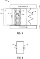
- FIG. 3 illustrates an example system 110 that uses inductor(s) in magnetic skyhook damper isolation, according to an example implementation.
- the system 110 includes a first component 112 moveable with respect to a second component 114, and a tuned magnetic dashpot 116 positioned between the first component 112 and the second component 114.
- the tuned magnetic dashpot 116 damps movement of the first component 112 relative to the second component 114.
- the first component 112 may be a base and the second component 114 may be a payload positioned on the base.
- movement/vibrations of the first component 112 are translated to the second component 114, and the tuned magnetic dashpot 116 operates to attenuate those vibrations that may be translated to the second component 114, for example.
- the first component 112 includes a frame of a vehicle and the second component 114 includes a body attached to the frame that would otherwise experience the same vibrations as experienced by the first component 112 if not for the tuned magnetic dashpot 116 positioned between the first component 112 and the second component 114 that attenuates vibrations experienced by the first component 112 relative to the second component 114.
- the tuned magnetic dashpot 116 includes a voice coil 118 coupled to the first component 112, a magnet 120 coupled to the second component 114 and concentric with the voice coil 118, and an inductor 122 positioned in series with the voice coil 118 to enable frequency dependent damping, such that damping below a critical frequency 2 ⁇ n is greater than damping above the critical frequency 2 ⁇ n , and ⁇ n is a natural frequency of movement of the first component 112 relative to the second component 114.
- the voice coil 118 may be physically connected to or affixed to the first component 112, and the magnet 120 may be physically connected to or affixed to the second component 114.
- the system 110 may be reversed in which the second component 114 is the base and the first component 112 is the payload, such that the voice coil 118 is physically connected or affixed to the first component 112 (payload) and the magnet 120 is physically connected or affixed to the second component 114 (base).
- the system 110 also includes a spring 124 that extends between the first component 112 and the second component 114 to control relative positioning of the first component 112 to the second component 114.
- the spring 124 acts to further attenuate vibrations experienced by the first component 112 relative to the second component 114.
- the tuned magnetic dashpot 116 can further include a frame 126, and the voice coil 118 can be supported in the frame 126, the magnet 120 is movable relative to the frame 126 via the voice coil 118, and the inductor 122 can be positioned in the frame 126.
- the magnet 120 of the tuned magnetic dashpot 116 provides a moving mass for the tuned magnetic dashpot 116 that reciprocates concentrically within the voice coil 118.
- the voice coil 118 is not actively powered to move the magnet 120 up or down from a neutral position, and thus, the tuned magnetic dashpot 116 uses no external power source. Rather passive isolation is used such that energy experienced by the first component 112 is dissipated by the tuned magnetic dashpot 116. For example, a velocity of the magnet 120 (due to motion of the second component 114 to which the magnet is affixed) in a vicinity of the voice coil 118 produces back electromotive force in the voice coil 118.
- an effective damping coefficient is bl 2 r , where bl is the voice coil force coefficient that relates force to applied current and r is a resistance of the voice coil 118 and the wire that shorts the voice coil 118.
- the voice coil 118 and the magnet 120 combination when using the voice coil 118 and the magnet 120 combination in parallel with the spring 124, the voice coil 118 and the magnet 120 combination can be used as a dashpot that absorbs energy and limits a response at resonance.
- a passive isolation system designed with a voice coil dashpot would behave either like the line labelled ⁇ 1 or ⁇ 2 with an amplitude at resonance determined by the damping coefficient, which depends on a strength of the voice coil force coefficient. While the more damped curve corresponding to ⁇ 2 has a lower amplitude at resonance, the behavior above 2 ⁇ n is degraded with roll off approaching 1/s. Since a goal of an isolation system is a roll off of 1/s 2 , a high voice coil force coefficient damper may not be able to achieve this goal.
- the magnet moves relative to the voice coil to induce current in the voice coil and the current is dissipated by resistance of the voice coil that looks like damping to an external mechanical system.
- Such systems work at low frequencies, but operation begins to degrade between 200Hz-500Hz and attenuation discontinues at about 500 Hz.
- the tuned magnetic dashpot 116 uses the inductor 122 in series with the voice coil 118, which acts to decrease its performance as a dashpot at high frequencies.
- a value of the inductor 122 is selected in a deterministic manner to control where the tuned magnetic dashpot 116 stops attenuation to achieve skyhook damping.
- the tuned magnetic dashpot 116 has an amount of passive inductance in the voice coil 118, and a transition frequency where damping decreases significantly is in the 100's of Hz, which is much higher than a desired isolation frequency of most systems.
- the addition of external inductance (e.g., the inductor 122) in series with the voice coil 118 and tuning a value of the inductor 122 enable a much lower transition frequency to be achieved.
- the addition of the inductor 122 that is tunable thus can achieve frequency dependent damping, with high damping below the critical frequency 2 ⁇ n and low damping above the critical frequency 2 ⁇ n .
- the inductor 122 reduces an amplitude of displacement of the first component 112 relative to the second component 114 at resonance.
- Figure 3 illustrates one inductor in series with the voice coil 118, however, more than one inductor may be used.
- the inductor 122 may also be a tunable or variable inductor, as described below.
- system 110 in Figure 3 illustrates one tuned magnetic dashpot 116 for a one-degree-of-freedom isolator, although additional dampers may be included.
- the system 110 may include a plurality of tuned magnetic dashpots arranged in a hexapod for a six-degree-of-freedom isolator.
- FIG. 4 is a schematic diagram illustrating inductance in the tuned magnetic dashpot 116, according to an example implementation.
- the voice coil 118 has an inherent inductance 128, which is shown to be in series with externally added inductance due to the inductor 122.
- the voice coil 118 and the magnet 120 operate to provide a back electromotive force (EMF) for damping movement of the first component 112 relative to the second component 114, and the inductor 122 is thus an additional inductance added in series with the voice coil 118 to modify the back EMF provided at certain frequencies.
- EMF back electromotive force
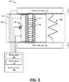
- Figure 5 illustrates the example system 110 with inductor tuning functionality, according to an example implementation.
- a computing device 130 includes one or more processor(s) 132 that is coupled to the first component 112, the second component 114, the inductor 122 and wires connecting the inductor 122 to the voice coil 118.
- the inductance of the inductor 122 is based on a shut-off frequency of the tuned magnetic dashpot 116, such that above the shut-off frequency, the tuned magnetic dashpot 116 provides approximately no damping of movement of the first component 112 relative to the second component 114.
- the voice coil 118 has the inherent inductance bl, and a value of the inductor 122 can be tuned to achieve a desired shut-off frequency where attenuation discontinues.
- the computing device 130 receives feedback of movement or displacement of the first component 112 and the second component 114, and adjusts a value of the inductor 122 accordingly.
- the processor(s) 132 may be a general-purpose processor or a special purpose processor (e.g., digital signal processors, application specific integrated circuits, etc.).
- the processor(s) 132 can be configured to execute program instructions (e.g., computer-readable program instructions) that are stored in data storage 134 and executable to provide functionality of determining a value of the inductor 122 described herein.
- the data storage 134 may include or take the form of one or more computer-readable storage media that can be read or accessed by the processor(s) 132.
- the computer-readable storage media can include volatile and/or non-volatile storage components, such as optical, magnetic, organic or other memory or disc storage, which can be integrated in whole or in part with the processor(s) 132.
- the data storage 134 is considered non-transitory computer readable media.
- m is a mass of the first component 112
- y is a displacement of the first component 112
- x is a displacement of the second component 114
- i current through the inductor 122
- f is a force exerted by the voice coil 118
- r is a resistance of the voice coil 118 and the inductor 122
- / an internal inductance of the voice coil 118
- l ext is an inductance of the inductor 122
- bl is a coefficient of the voice coil force
- k is a spring constant.
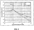
- Figure 6 is an example plot illustrating transmissibility of the tuned magnetic dashpot 116, for various values of damping ⁇ , according to an example implementation.
- a shorted dashpot with relatively high damping and roll off approaching 1/s may be produced, as shown by curve 138.
- a dashpot with external inductance (e.g., value of the inductor 122 ( l ext )) of about sixty (60) times the inherent/internal inductance of the voice coil 118 may be achieved, as shown by curve 140.
- the curve 140 has a very small increase in amplitude at resonance as compared to the curve 138 (e.g., about 20% increase), but experiences a 66% decrease in transmissibility at ten (10) times the isolator frequency as compared to the curve 138.
- the line roll off of the curve 140 also closely matches the desired 1/s 2 roll off of the curve 136 with performance increasing as compared to the curve 138 as frequency increases.
- the tuned magnetic dashpot 116 with external inductance achieves desired performance characteristics of the lightly damped isolator (represented by the curve 136) at roll off, while also achieving desired performance characteristics of the shorted dashpot (represented by the curve 138) at resonance.
- high damping is achieved below the critical frequency 2 ⁇ n (where ⁇ n is a natural frequency of movement of components) to reduce the amplification peak as seen by a traditional isolator (represented by the curve 136), and low damping is achieved above 2 ⁇ n to improve a decay rate as seen by the shorted dashpot (represented by the curve 138).
- Inductance values of the inductor 122 can be tuned until performance is seen by the tuned magnetic dashpot 116 that matches or closely resembles that as seen by the curve 140.
- the inductance of the inductor 122 can be selected to be approximately sixty (60) times the inherent inductance of the voice coil 118.
- Use of an external inductance in the tuned magnetic dashpot 116 improves performance of the isolator, and enables a tunable isolator to achieve lower amplitude at resonance and/or improved isolator performance.
- Figure 7 illustrates the example system 110 with an active isolation system 142 positioned between the first component 112 and the second component 114, according to an example implementation.
- the active isolation system 142 may be operated in parallel with the tuned magnetic dashpot 116.
- the tuned magnetic dashpot 116 may then be a backup damping system, for example.
- Figure 8 shows a flowchart of an example method 200 for damping movement of the first component 112 relative to the second component 114, according to an example embodiment.
- Method 200 shown in Figure 8 presents an embodiment of a method that, for example, could be used with the system 110 as shown and described herein, for example.
- flowcharts show functionality and operation of one possible implementation of present embodiments.
- components of the devices and/or systems may be configured to perform the functions such that the components are actually configured and structured (with hardware and/or software) to enable such performance.
- components of the devices and/or systems may be arranged to be adapted to, capable of, or suited for performing the functions, such as when operated in a specific manner.
- Method 200 may include one or more operations, functions, or actions as illustrated by one or more of blocks 202-206. Although the blocks are illustrated in a sequential order, these blocks may also be performed in parallel, and/or in a different order than those described herein. Also, the various blocks may be combined into fewer blocks, divided into additional blocks, and/or removed based upon the desired implementation.
- any of the blocks may represent a module, a segment, or a portion of program code, which includes one or more instructions executable by a processor for implementing specific logical functions or steps in the process.
- the program code may be stored on any type of computer readable medium or data storage, for example, such as a storage device including a disk or hard drive. Further, the program code can be encoded on a computer-readable storage media in a machine-readable format, or on other non-transitory media or articles of manufacture.
- the computer readable medium may include non-transitory computer readable medium or memory, for example, such as computer-readable media that stores data for short periods of time like register memory, processor cache and Random Access Memory (RAM).
- the computer readable medium may also include non-transitory media, such as secondary or persistent long term storage, like read only memory (ROM), optical or magnetic disks, compact-disc read only memory (CD-ROM), for example.
- the computer readable media may also be any other volatile or non-volatile storage systems.
- the computer readable medium may be considered a tangible computer readable storage medium, for example.
- blocks in Figure 8 may represent circuitry that is wired to perform the specific logical functions in the process.
- Alternative implementations are included within the scope of the examples of the present disclosure in which functions may be executed out of order from that shown or discussed, including substantially concurrent or in reverse order, depending on the functionality involved, as would be understood by those reasonably skilled in the art.
- the method 200 includes coupling the voice coil 118 to the first component 112.
- the method 200 includes coupling the magnet 120 to the second component 114 and concentric with the voice coil 118.
- the method includes positioning the inductor 122 in series with the voice coil 118 to enable frequency dependent damping, such that damping below a critical frequency 2 ⁇ n is greater than damping above the critical frequency 2 ⁇ n , where ⁇ n is a natural frequency of movement of the first component relative to the second component.
- FIG. 9 shows a flowchart of an example method for use with the method 200, according to an example embodiment.
- functions include operating the voice coil 118 and the magnet 120 to provide a back electromotive force (EMF) for damping movement of the first component 112 relative to the second component 114, and the inductor 122 is an additional inductance added in series with the voice coil 118 to modify the back EMF provided at certain frequencies.
- EMF back electromotive force
- FIG. 10 shows a flowchart of an example method for use with the method 200, according to an example embodiment.
- m is a mass of the first component 112
- y is a displacement of the first component 112
- x is a displacement of the second component 114
- i current through the inductor 122
- f is a force exerted by the voice coil 118
- r is a resistance of the voice coil 118 and the inductor 122
- l ext is an inductance of the inductor 122
- bl is
Landscapes
- Engineering & Computer Science (AREA)
- General Engineering & Computer Science (AREA)
- Physics & Mathematics (AREA)
- Mechanical Engineering (AREA)
- Acoustics & Sound (AREA)
- Aviation & Aerospace Engineering (AREA)
- Electromagnetism (AREA)
- Vibration Prevention Devices (AREA)
- Reciprocating, Oscillating Or Vibrating Motors (AREA)
Abstract
Description
- The present disclosure generally relates to isolation systems to isolate two portions of a vehicle from movement incurred by one of the portions, and more particularly, to a tuned magnetic dashpot for damping movement between components.
- Vibrations transmitted onto payloads in vehicles can cause problems. For example, if the vehicle is an automobile, vibrations cause discomfort. If the vehicle is a space launch vehicle, vibrations can jeopardize the mission. Thus, isolation systems are typically used to isolate a body of the vehicle from the payload to prevent transmission of the vibrations from the body to the payload.
- Isolation systems are well known in the art, which include passive systems, semi-active systems, and active systems. Passive systems utilize passive isolating devices such as mounts and shock absorbers to isolate a suspended member from shock and vibration inputs. Passive systems can provide adequate isolation, but usually only dissipate energy from the system.
- Semi-active systems have been developed that vary parameters of the isolation system in order to provide better isolation. For example, a semi-active system can incorporate controllable dampers for providing a controllable damper force as needed.
- Active systems further control movement of the isolated member in the system by using external power. An example active system is typically used in automobile to control movement of the wheels relative to the chassis or vehicle body, rather than using passive suspension where the movement is determined entirely by the road surface.
- With isolation systems, skyhook theory is an idea that all isolation systems are designed to achieve (whether passive, semi-active, or active), which includes having the system maintain a stable posture as if suspended by an imaginary hook in the sky, unaffected by external conditions. Thus, it is a goal of isolation systems to achieve little or no amplification of the system at resonance by adding a force to resist movement of the system. This can be achieved with active systems by implementing a sky-hook isolator that has a feedback link established between the body of the system and the actuator force so that the active control force can be made proportional to the body velocity and that there is no amplification below ωn (where ωn is a natural frequency of the system where the system tends to oscillate in the absence of a damping force).
- For a passive system, the skyhook design involves a trade-off between the resonance amplification and the high frequency attenuation. What is needed is a way of achieving isolation performance using passive isolation that is nearly the ideal performance of a skyhook without the need for active isolation and external power.
- In one example, a tuned magnetic dashpot for damping movement of a first component relative to a second component is described. The tuned magnetic dashpot comprises a voice coil coupled to the first component, a magnet coupled to the second component and concentric with the voice coil, and an inductor positioned in series with the voice coil to enable frequency dependent damping, such that damping below a
critical frequency 
critical frequency 
- In another example, a system is described that includes a first component moveable with respect to a second component, and a tuned magnetic dashpot positioned between the first component and the second component. The tuned magnetic dashpot is for damping movement of the first component relative to the second component. The tuned magnetic dashpot includes a voice coil coupled to the first component, a magnet coupled to the second component and concentric with the voice coil, and an inductor positioned in series with the voice coil to enable frequency dependent damping, such that damping below a
critical frequency 
critical frequency 
- The features, functions, and advantages that have been discussed can be achieved independently in various embodiments or may be combined in yet other embodiments further details of which can be seen with reference to the following description and drawings.
- The novel features believed characteristic of the illustrative embodiments are set forth in the appended claims. The illustrative embodiments, however, as well as a preferred mode of use, further objectives and descriptions thereof, will best be understood by reference to the following detailed description of an illustrative embodiment of the present disclosure when read in conjunction with the accompanying Figures.
-
Figure 1 is an example illustration of a system in which a disturbance force is generated and damped, according to an example implementation. -
Figure 2 is an example plot illustrating transmissibility of an example passive isolator, such as the system shown inFigure 1 , for various values of damping ξ, according to an example implementation. -
Figure 3 illustrates an example system that uses inductor(s) in magnetic skyhook damper isolation, according to an example implementation. -
Figure 4 is a schematic diagram illustrating inductance in the tuned magnetic dashpot, according to an example implementation. -
Figure 5 illustrates the example system with inductor tuning functionality, according to an example implementation. -
Figure 6 is an example plot illustrating transmissibility of the tuned magnetic dashpot, for various values of damping ξ, according to an example implementation. -
Figure 7 illustrates the example system with an active isolation system positioned between the first component and the second component, according to an example implementation. -
Figure 8 shows a flowchart of an example method for damping movement of the first component relative to the second component, according to an example embodiment. -
Figure 9 shows a flowchart of an example method for use with the method, according to an example embodiment. -
Figure 10 shows a flowchart of an example method for use with the method, according to an example embodiment. - Disclosed embodiments will now be described more fully hereinafter with reference to the accompanying Figures, in which some, but not all of the disclosed embodiments are shown. Indeed, several different embodiments may be described and should not be construed as limited to the embodiments set forth herein. Rather, these embodiments are described so that this disclosure will be thorough and complete and will fully convey the scope of the disclosure to those skilled in the art.
- It is a goal of active isolation systems to achieve little or no amplification at resonance.
Figure 1 is an example illustration of asystem 100 in which a disturbance force is generated and damped, according to an example implementation. Thesystem 100 includes afirst mass 102 coupled to asecond mass 104 via aspring 106 and adashpot 108. Thefirst mass 102 causes a displacement xd of a supporting structure (e.g., dirty body) and the system output is a displacement xc of the second mass 104 (e.g., clean body). Thespring 106 and thedashpot 108 operate to damp the disturbance some amount, and a transmissibility of the system 100 (defined in terms of a function between displacement of the dirty body or thefirst mass 102 and that of the clean body or second mass 104) can be determined as xc /xd . -
Figure 2 is an example plot illustrating transmissibility of an example passive isolator, such as thesystem 100 shown inFigure 1 , for various values of damping ξ, according to an example implementation.Figure 2 illustrates a curve for an objective of an example active isolation as well in which no amplification occurs below 1 Hz, and above 1 Hz, attenuation begins. - As shown in
Figure 2 , all curves for the example passive isolator are larger than 1 Hz for

critical frequency 
- When ξ=0, a high frequency decay rate is 1/s2, that is -40 dB/decade, while very large amplitudes occur near a corner frequency ωn (the natural frequency of the spring-mass system). Damping then reduces the amplitude at resonance, but also tends to reduce effectiveness at high frequency as the high frequency decay rate becomes 1/s (-20 dB/decade).
- A design of a passive isolator involves a trade-off between the resonance amplification and the high frequency attenuation. An ideal isolator may have a frequency dependent damping, with high damping below the
critical frequency 

Figure 2 ). - An ability to achieve high damping at resonance without sacrificing 1/s2 rolloff (in Laplace domain or 1/ω 2 in time domain), as shown in
Figure 2 , is referred to as skyhook damping. Skyhook damping refers to maintaining stability in a system as if suspended by an imaginary hook in the sky, and thus if a damper were attached to an inertial reference that followed the payload around (a skyhook), high damping at resonance without sacrificing 1/s2 rolloff can be achieved. Active isolation techniques are often designed to achieve skyhook damping with added complexity of a feedback control system and a need for external power. Within examples described herein, systems and methods for achieving isolation performance that is nearly ideal are described without the need for active isolation. The new approach can be made entirely passive, and does not require external power, for example. - In some examples herein, methods of achieving vibration isolation performance nearly as good as from active isolation are shown with use of a voice coil/magnetic dashpot and an external inductor. An example passive isolator is thus capable of achieving skyhook damping at high frequencies without a need any external power sources.
-
Figure 3 illustrates anexample system 110 that uses inductor(s) in magnetic skyhook damper isolation, according to an example implementation. Thesystem 110 includes afirst component 112 moveable with respect to asecond component 114, and a tunedmagnetic dashpot 116 positioned between thefirst component 112 and thesecond component 114. The tunedmagnetic dashpot 116 damps movement of thefirst component 112 relative to thesecond component 114. For example, thefirst component 112 may be a base and thesecond component 114 may be a payload positioned on the base. As a result, movement/vibrations of thefirst component 112 are translated to thesecond component 114, and the tunedmagnetic dashpot 116 operates to attenuate those vibrations that may be translated to thesecond component 114, for example. - In a specific example, the
first component 112 includes a frame of a vehicle and thesecond component 114 includes a body attached to the frame that would otherwise experience the same vibrations as experienced by thefirst component 112 if not for the tunedmagnetic dashpot 116 positioned between thefirst component 112 and thesecond component 114 that attenuates vibrations experienced by thefirst component 112 relative to thesecond component 114. - The tuned
magnetic dashpot 116 includes avoice coil 118 coupled to thefirst component 112, amagnet 120 coupled to thesecond component 114 and concentric with thevoice coil 118, and aninductor 122 positioned in series with thevoice coil 118 to enable frequency dependent damping, such that damping below acritical frequency 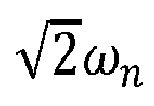
critical frequency 
first component 112 relative to thesecond component 114. - The
voice coil 118 may be physically connected to or affixed to thefirst component 112, and themagnet 120 may be physically connected to or affixed to thesecond component 114. In other examples, thesystem 110 may be reversed in which thesecond component 114 is the base and thefirst component 112 is the payload, such that thevoice coil 118 is physically connected or affixed to the first component 112 (payload) and themagnet 120 is physically connected or affixed to the second component 114 (base). - The
system 110 also includes aspring 124 that extends between thefirst component 112 and thesecond component 114 to control relative positioning of thefirst component 112 to thesecond component 114. Thespring 124 acts to further attenuate vibrations experienced by thefirst component 112 relative to thesecond component 114. - The tuned
magnetic dashpot 116 can further include aframe 126, and thevoice coil 118 can be supported in theframe 126, themagnet 120 is movable relative to theframe 126 via thevoice coil 118, and theinductor 122 can be positioned in theframe 126. - The
magnet 120 of the tunedmagnetic dashpot 116 provides a moving mass for the tunedmagnetic dashpot 116 that reciprocates concentrically within thevoice coil 118. Thevoice coil 118 is not actively powered to move themagnet 120 up or down from a neutral position, and thus, the tunedmagnetic dashpot 116 uses no external power source. Rather passive isolation is used such that energy experienced by thefirst component 112 is dissipated by the tunedmagnetic dashpot 116. For example, a velocity of the magnet 120 (due to motion of thesecond component 114 to which the magnet is affixed) in a vicinity of thevoice coil 118 produces back electromotive force in thevoice coil 118. If thevoice coil 118 is shorted, an effective damping coefficient is
voice coil 118 and the wire that shorts thevoice coil 118. - As shown in
Figure 3 , when using thevoice coil 118 and themagnet 120 combination in parallel with thespring 124, thevoice coil 118 and themagnet 120 combination can be used as a dashpot that absorbs energy and limits a response at resonance. - In
Figure 2 , a passive isolation system designed with a voice coil dashpot would behave either like the line labelled ξ 1 or ξ 2 with an amplitude at resonance determined by the damping coefficient, which depends on a strength of the voice coil force coefficient. While the more damped curve corresponding to ξ 2 has a lower amplitude at resonance, the behavior above
- For example, in existing voice coil/magnet systems, the magnet moves relative to the voice coil to induce current in the voice coil and the current is dissipated by resistance of the voice coil that looks like damping to an external mechanical system. Such systems work at low frequencies, but operation begins to degrade between 200Hz-500Hz and attenuation discontinues at about 500 Hz.
- Within examples described herein, rather than shorting the
voice coil 118, the tunedmagnetic dashpot 116 uses theinductor 122 in series with thevoice coil 118, which acts to decrease its performance as a dashpot at high frequencies. A value of theinductor 122 is selected in a deterministic manner to control where the tunedmagnetic dashpot 116 stops attenuation to achieve skyhook damping. - The tuned
magnetic dashpot 116 has an amount of passive inductance in thevoice coil 118, and a transition frequency where damping decreases significantly is in the 100's of Hz, which is much higher than a desired isolation frequency of most systems. The addition of external inductance (e.g., the inductor 122) in series with thevoice coil 118 and tuning a value of theinductor 122 enable a much lower transition frequency to be achieved. The addition of theinductor 122 that is tunable thus can achieve frequency dependent damping, with high damping below thecritical frequency 
critical frequency 
inductor 122 reduces an amplitude of displacement of thefirst component 112 relative to thesecond component 114 at resonance. -
Figure 3 illustrates one inductor in series with thevoice coil 118, however, more than one inductor may be used. Theinductor 122 may also be a tunable or variable inductor, as described below. - In addition, the
system 110 inFigure 3 illustrates one tunedmagnetic dashpot 116 for a one-degree-of-freedom isolator, although additional dampers may be included. For example, thesystem 110 may include a plurality of tuned magnetic dashpots arranged in a hexapod for a six-degree-of-freedom isolator. -
Figure 4 is a schematic diagram illustrating inductance in the tunedmagnetic dashpot 116, according to an example implementation. Thevoice coil 118 has aninherent inductance 128, which is shown to be in series with externally added inductance due to theinductor 122. Thevoice coil 118 and themagnet 120 operate to provide a back electromotive force (EMF) for damping movement of thefirst component 112 relative to thesecond component 114, and theinductor 122 is thus an additional inductance added in series with thevoice coil 118 to modify the back EMF provided at certain frequencies. -
Figure 5 illustrates theexample system 110 with inductor tuning functionality, according to an example implementation. InFigure 5 , acomputing device 130 includes one or more processor(s) 132 that is coupled to thefirst component 112, thesecond component 114, theinductor 122 and wires connecting theinductor 122 to thevoice coil 118. - The inductance of the
inductor 122 is based on a shut-off frequency of the tunedmagnetic dashpot 116, such that above the shut-off frequency, the tunedmagnetic dashpot 116 provides approximately no damping of movement of thefirst component 112 relative to thesecond component 114. Thevoice coil 118 has the inherent inductance bl, and a value of theinductor 122 can be tuned to achieve a desired shut-off frequency where attenuation discontinues. Thecomputing device 130 receives feedback of movement or displacement of thefirst component 112 and thesecond component 114, and adjusts a value of theinductor 122 accordingly. - The processor(s) 132 may be a general-purpose processor or a special purpose processor (e.g., digital signal processors, application specific integrated circuits, etc.). The processor(s) 132 can be configured to execute program instructions (e.g., computer-readable program instructions) that are stored in
data storage 134 and executable to provide functionality of determining a value of theinductor 122 described herein. Thedata storage 134 may include or take the form of one or more computer-readable storage media that can be read or accessed by the processor(s) 132. The computer-readable storage media can include volatile and/or non-volatile storage components, such as optical, magnetic, organic or other memory or disc storage, which can be integrated in whole or in part with the processor(s) 132. Thedata storage 134 is considered non-transitory computer readable media. - To determine a value of the
inductor 122, a transmissibility of the tunedmagnetic dashpot 116 may be analyzed, which is given by y/x as determined by equations of motion as follows:


first component 112, y is a displacement of thefirst component 112, x is a displacement of thesecond component 114, i is current through theinductor 122, f is a force exerted by thevoice coil 118, r is a resistance of thevoice coil 118 and theinductor 122, / is an internal inductance of thevoice coil 118, lext is an inductance of theinductor 122, bl is a coefficient of the voice coil force, and k is a spring constant. Solving these three equations for the transmissibility y/x as desired results in a determined value of the inductor 122 (e.g., lext ). -
Figure 6 is an example plot illustrating transmissibility of the tunedmagnetic dashpot 116, for various values of damping ξ, according to an example implementation. - In one example, a lightly damped isolator with ξ very small may be produced (which matches ξ = 0 curve in
Figure 2 ) and exhibits 1/s2 roll off, as shown bycurve 136. In another example, a shorted dashpot with relatively high damping and roll off approaching 1/s, may be produced, as shown bycurve 138. - However, by tuning the
inductor 122, a dashpot with external inductance (e.g., value of the inductor 122 (lext )) of about sixty (60) times the inherent/internal inductance of thevoice coil 118 may be achieved, as shown bycurve 140. Thecurve 140 has a very small increase in amplitude at resonance as compared to the curve 138 (e.g., about 20% increase), but experiences a 66% decrease in transmissibility at ten (10) times the isolator frequency as compared to thecurve 138. The line roll off of thecurve 140 also closely matches the desired 1/s2 roll off of thecurve 136 with performance increasing as compared to thecurve 138 as frequency increases. - Thus, the tuned
magnetic dashpot 116 with external inductance (e.g., the curve 140) achieves desired performance characteristics of the lightly damped isolator (represented by the curve 136) at roll off, while also achieving desired performance characteristics of the shorted dashpot (represented by the curve 138) at resonance. In some examples, by tuning theinductor 122, high damping is achieved below thecritical frequency 

- Inductance values of the
inductor 122 can be tuned until performance is seen by the tunedmagnetic dashpot 116 that matches or closely resembles that as seen by thecurve 140. In one example, the inductance of theinductor 122 can be selected to be approximately sixty (60) times the inherent inductance of thevoice coil 118. - Use of an external inductance in the tuned
magnetic dashpot 116 improves performance of the isolator, and enables a tunable isolator to achieve lower amplitude at resonance and/or improved isolator performance. -
Figure 7 illustrates theexample system 110 with anactive isolation system 142 positioned between thefirst component 112 and thesecond component 114, according to an example implementation. Theactive isolation system 142 may be operated in parallel with the tunedmagnetic dashpot 116. InFigure 7 , the tunedmagnetic dashpot 116 may then be a backup damping system, for example. -
Figure 8 shows a flowchart of anexample method 200 for damping movement of thefirst component 112 relative to thesecond component 114, according to an example embodiment.Method 200 shown inFigure 8 presents an embodiment of a method that, for example, could be used with thesystem 110 as shown and described herein, for example. It should be understood that for this and other processes and methods disclosed herein, flowcharts show functionality and operation of one possible implementation of present embodiments. In some instances, components of the devices and/or systems may be configured to perform the functions such that the components are actually configured and structured (with hardware and/or software) to enable such performance. In other examples, components of the devices and/or systems may be arranged to be adapted to, capable of, or suited for performing the functions, such as when operated in a specific manner.Method 200 may include one or more operations, functions, or actions as illustrated by one or more of blocks 202-206. Although the blocks are illustrated in a sequential order, these blocks may also be performed in parallel, and/or in a different order than those described herein. Also, the various blocks may be combined into fewer blocks, divided into additional blocks, and/or removed based upon the desired implementation. - It should be understood that for this and other processes and methods disclosed herein, flowcharts show functionality and operation of one possible implementation of present examples. In this regard, any of the blocks may represent a module, a segment, or a portion of program code, which includes one or more instructions executable by a processor for implementing specific logical functions or steps in the process. The program code may be stored on any type of computer readable medium or data storage, for example, such as a storage device including a disk or hard drive. Further, the program code can be encoded on a computer-readable storage media in a machine-readable format, or on other non-transitory media or articles of manufacture. The computer readable medium may include non-transitory computer readable medium or memory, for example, such as computer-readable media that stores data for short periods of time like register memory, processor cache and Random Access Memory (RAM). The computer readable medium may also include non-transitory media, such as secondary or persistent long term storage, like read only memory (ROM), optical or magnetic disks, compact-disc read only memory (CD-ROM), for example. The computer readable media may also be any other volatile or non-volatile storage systems. The computer readable medium may be considered a tangible computer readable storage medium, for example.
- In addition, blocks in
Figure 8 , and within other processes and methods disclosed herein, may represent circuitry that is wired to perform the specific logical functions in the process. Alternative implementations are included within the scope of the examples of the present disclosure in which functions may be executed out of order from that shown or discussed, including substantially concurrent or in reverse order, depending on the functionality involved, as would be understood by those reasonably skilled in the art. - At
block 202, themethod 200 includes coupling thevoice coil 118 to thefirst component 112. Atblock 204 themethod 200 includes coupling themagnet 120 to thesecond component 114 and concentric with thevoice coil 118. Atblock 206, the method includes positioning theinductor 122 in series with thevoice coil 118 to enable frequency dependent damping, such that damping below acritical frequency 
critical frequency 
-
Figure 9 shows a flowchart of an example method for use with themethod 200, according to an example embodiment. Atblock 208, functions include operating thevoice coil 118 and themagnet 120 to provide a back electromotive force (EMF) for damping movement of thefirst component 112 relative to thesecond component 114, and theinductor 122 is an additional inductance added in series with thevoice coil 118 to modify the back EMF provided at certain frequencies. -
Figure 10 shows a flowchart of an example method for use with themethod 200, according to an example embodiment. Atblock 210, functions include determining a value of inductance of theinductor 122 based on a transmissibility of the tunedmagnetic dashpot 116 given by y/x determined by equations of motion as follows:


first component 112, y is a displacement of thefirst component 112, x is a displacement of thesecond component 114, i is current through theinductor 122, f is a force exerted by thevoice coil 118, r is a resistance of thevoice coil 118 and theinductor 122, / is an internal inductance of thevoice coil 118, lext is an inductance of theinductor 122, bl is a coefficient of the voice coil force, and k is a spring constant. - By the term "substantially" and "about" used herein, it is meant that the recited characteristic, parameter, or value need not be achieved exactly, but that deviations or variations, including for example, tolerances, measurement error, measurement accuracy limitations and other factors known to skill in the art, may occur in amounts that do not preclude the effect the characteristic was intended to provide.
Different examples of the system(s), device(s), and method(s) disclosed herein include a variety of components, features, and functionalities. It should be understood that the various examples of the system(s), device(s), and method(s) disclosed herein may include any of the components, features, and functionalities of any of the other examples of the system(s), device(s), and method(s) disclosed herein in any combination, and all of such possibilities are intended to be within the scope of the disclosure.
Further, the disclosure comprises embodiments according to the following clauses: -
Clause 1. A tuned magnetic dashpot for damping movement of a first component relative to a second component, the tuned magnetic dashpot comprising:- a voice coil coupled to the first component;
- a magnet coupled to the second component and concentric with the voice coil; and
- an inductor positioned in series with the voice coil to enable frequency dependent damping, such that damping below a
critical frequency 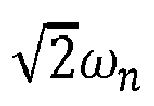
critical frequency 
-
Clause 2. The tuned magnetic dashpot ofClause 1, wherein the tuned magnetic dashpot uses no external power source. - Clause 3. The tuned magnetic dashpot of
Clause 1, wherein the voice coil has an inherent inductance and wherein the voice coil and the magnet operate to provide a back electromotive force (EMF) for damping movement of the first component relative to the second component, and
wherein the inductor is an additional inductance added in series with the voice coil to modify the back EMF provided at certain frequencies. - Clause 4. The tuned magnetic dashpot of Clause 3, wherein an inductance of the inductor is based on a shut-off frequency of the tuned magnetic dashpot, wherein above the shut-off frequency, the tuned magnetic dashpot provides approximately no damping of movement of the first component relative to the second component.
-
Clause 5. The tuned magnetic dashpot ofClause 1, wherein a spring extends between the first component and the second component to control relative positioning of the first component to the second component. - Clause 6. The tuned magnetic dashpot of
Clause 5, wherein a transmissibility of the tuned magnetic dashpot is given by y/x determined by equations of motion as follows:


- Clause 7. The tuned magnetic dashpot of Clause 6, wherein the inductor reduces an amplitude of displacement of the first component at resonance.
- Clause 8. The tuned magnetic dashpot of
Clause 1, wherein the voice coil has an inherent inductance and wherein the inductor has an inductance of approximately 60 times the inherent inductance of the voice coil. - Clause 9. The tuned magnetic dashpot of
Clause 1, further comprising a frame, wherein:- the voice coil is supported in the frame;
- the magnet is movable relative to the frame via the voice coil; and
- the inductor is positioned in the frame.
-
Clause 10. A system, comprising:- a first component moveable with respect to a second component; and
- a tuned magnetic dashpot positioned between the first component and the second component, the tuned magnetic dashpot for damping movement of the first component relative to the second component, the tuned magnetic dashpot including:
- a voice coil coupled to the first component;
- a magnet coupled to the second component and concentric with the voice coil; and
- an inductor positioned in series with the voice coil to enable frequency dependent damping, such that damping below a
critical frequency 
critical frequency 
- Clause 11. The system of
Clause 10, further comprising a plurality of tuned magnetic dashpots arranged in a hexapod. - Clause 12. The system of
Clause 10, wherein the tuned magnetic dashpot uses no external power source. - Clause 13. The system of
Clause 10, wherein the voice coil has an inherent inductance and wherein the voice coil and the magnet operate to provide a back electromotive force (EMF) for damping movement of the first component relative to the second component, and
wherein the inductor is an additional inductance added in series with the voice coil to modify the back EMF provided at certain frequencies. - Clause 14. The system of Clause 13, wherein an inductance of the inductor is based on a shut-off frequency of the tuned magnetic dashpot, wherein above the shut-off frequency, the tuned magnetic dashpot provides approximately no damping of movement of the first component relative to the second component.
- Clause 15. The system of
Clause 10, wherein a spring extends between the first component and the second component to control relative positioning of the first component to the second component. - Clause 16. The system of Clause 15, wherein a transmissibility of the tuned magnetic dashpot is given by y/x determined by equations of motion as follows:


- Clause 17. The system of Clause 16, wherein the inductor reduces an amplitude of displacement of the first component at resonance.
- Clause 18. The system of
Clause 10, wherein the voice coil has an inherent inductance and wherein the inductor has an inductance of approximately 60 times the inherent inductance of the voice coil. - Clause 19. The system of
Clause 10, wherein the tuned magnetic dashpot further includes a frame, and wherein:- the voice coil is supported in the frame;
- the magnet is movable relative to the frame via the voice coil; and
- the inductor is positioned in the frame.
-
Clause 20. The system ofClause 10, further comprising:
an active isolation system positioned between the first component and the second component, the active isolation system operated in parallel with the tuned magnetic dashpot. - The description of the different advantageous arrangements has been presented for purposes of illustration and description, and is not intended to be exhaustive or limited to the examples in the form disclosed. Many modifications and variations will be apparent to those of ordinary skill in the art. Further, different advantageous examples may describe different advantages as compared to other advantageous examples. The example or examples selected are chosen and described in order to best explain the principles of the examples, the practical application, and to enable others of ordinary skill in the art to understand the disclosure for various examples with various modifications as are suited to the particular use contemplated.
Claims (15)
- A tuned magnetic dashpot (108) for damping movement of a first component (112) relative to a second component (114), the tuned magnetic dashpot comprising:a voice coil (118) coupled to the first component;a magnet (120) coupled to the second component and concentric with the voice coil; andan inductor (122) positioned in series with the voice coil to enable frequency dependent damping, such that damping below a critical frequency


- The tuned magnetic dashpot (108) of claim 1, wherein the voice coil (118) has an inherent inductance and wherein the voice coil and the magnet (120) operate to provide a back electromotive force (EMF) for damping movement of the first component (112) relative to the second component (114), and
wherein the inductor (122) is an additional inductance added in series with the voice coil to modify the back EMF provided at certain frequencies. - The tuned magnetic dashpot (108) of any of claims 1-2, wherein an inductance of the inductor (122) is based on a shut-off frequency of the tuned magnetic dashpot, wherein above the shut-off frequency, the tuned magnetic dashpot provides approximately no damping of movement of the first component (112) relative to the second component (114).
- The tuned magnetic dashpot (108) of any of claims 1-3, wherein a spring (106) extends between the first component (112) and the second component (114) to control relative positioning of the first component to the second component.
- The tuned magnetic dashpot (108) of any of claims 1-4, wherein the voice coil (118) has an inherent inductance and wherein the inductor (122) has an inductance of approximately 60 times the inherent inductance of the voice coil.
- The tuned magnetic dashpot (108) of any of claims 1-5, further comprising a frame (126), wherein:the voice coil (118) is supported in the frame;the magnet (120) is movable relative to the frame via the voice coil; andthe inductor (122) is positioned in the frame.
- A system (110), comprising:a first component (112) moveable with respect to a second component (114); anda tuned magnetic dashpot (108) positioned between the first component and the second component, the tuned magnetic dashpot for damping movement of the first component relative to the second component, the tuned magnetic dashpot including:a voice coil (118) coupled to the first component;a magnet (120) coupled to the second component and concentric with the voice coil; andan inductor (122) positioned in series with the voice coil to enable frequency dependent damping, such that damping below a critical frequency


- The system (110) of claim 7, further comprising a plurality of tuned magnetic dashpots (108) arranged in a hexapod.
- The system (110) of any of claims 7-8, wherein the tuned magnetic dashpot (108) uses no external power source.
- The system (110) of any of claims 7-9, wherein the voice coil (118) has an inherent inductance and wherein the voice coil and the magnet (120) operate to provide a back electromotive force (EMF) for damping movement of the first component (112) relative to the second component (114), and
wherein the inductor (122) is an additional inductance added in series with the voice coil to modify the back EMF provided at certain frequencies. - The system (110) of any of claims 7-10, wherein an inductance of the inductor (122) is based on a shut-off frequency of the tuned magnetic dashpot (108), wherein above the shut-off frequency, the tuned magnetic dashpot provides approximately no damping of movement of the first component (112) relative to the second component (114).
- The system (110) of any of claims 7-11, wherein a spring (106) extends between the first component (112) and the second component (114) to control relative positioning of the first component to the second component.
- The system (110) of any of claims 7-12, wherein the voice coil (118) has an inherent inductance and wherein the inductor (122) has an inductance of approximately 60 times the inherent inductance of the voice coil.
- The system (110) of any of claims 7-13, wherein the tuned magnetic dashpot (108) further includes a frame (126), and wherein:the voice coil (118) is supported in the frame;the magnet (120) is movable relative to the frame via the voice coil; andthe inductor (122) is positioned in the frame.
- The system (110) of any of claims 7-14, further comprising:
an active isolation system positioned between the first component (112) and the second component (114), the active isolation system operated in parallel with the tuned magnetic dashpot (108).
Applications Claiming Priority (1)
| Application Number | Priority Date | Filing Date | Title |
|---|---|---|---|
| US15/727,152 US10295011B2 (en) | 2017-10-06 | 2017-10-06 | Systems and tuned magnetic dashpots for using inductor(s) in magnetic skyhook damper isolation |
Publications (2)
| Publication Number | Publication Date |
|---|---|
| EP3467339A1 true EP3467339A1 (en) | 2019-04-10 |
| EP3467339B1 EP3467339B1 (en) | 2019-11-13 |
Family
ID=63579134
Family Applications (1)
| Application Number | Title | Priority Date | Filing Date |
|---|---|---|---|
| EP18194167.5A Active EP3467339B1 (en) | 2017-10-06 | 2018-09-13 | Magnetic systems and tuned dampers for the use of inductance(s) in the insulation of a skyhook magnetic damper |
Country Status (7)
| Country | Link |
|---|---|
| US (1) | US10295011B2 (en) |
| EP (1) | EP3467339B1 (en) |
| JP (1) | JP2019082247A (en) |
| CN (1) | CN109630581B (en) |
| BR (1) | BR102018070321A2 (en) |
| CA (1) | CA3016324C (en) |
| ES (1) | ES2768093T3 (en) |
Families Citing this family (5)
| Publication number | Priority date | Publication date | Assignee | Title |
|---|---|---|---|---|
| US11073758B2 (en) * | 2018-10-31 | 2021-07-27 | Canon Kabushiki Kaisha | Imprint apparatus control, control method and manufacturing method |
| CN110578297A (en) * | 2019-08-27 | 2019-12-17 | 河海大学 | An Eddy Current Damper Applicable to Any Vibration Direction of Cable |
| CN113147307B (en) * | 2021-06-03 | 2022-08-05 | 山东理工大学 | Inversion control method of active suspension based on reference model |
| CN113511348B (en) * | 2021-07-15 | 2022-10-25 | 兰州空间技术物理研究所 | Eddy current damping vibration-damping heat-insulating device of vertical thruster |
| CN116787982B (en) * | 2022-03-17 | 2024-10-11 | 比亚迪股份有限公司 | Semi-active suspension damping compensation method, device, medium and vehicle |
Citations (4)
| Publication number | Priority date | Publication date | Assignee | Title |
|---|---|---|---|---|
| JPH01203730A (en) * | 1988-02-09 | 1989-08-16 | Nec Corp | Damper gear |
| WO2003060345A1 (en) * | 2002-01-15 | 2003-07-24 | Honeywell International Inc. | Tuned mass damper using a hexapod |
| WO2006106134A1 (en) * | 2005-04-06 | 2006-10-12 | Bae Systems Plc | Vibration isolation |
| US20110227425A1 (en) * | 2010-03-16 | 2011-09-22 | Empire Technology Development Llc | Suspension system for vehicle |
Family Cites Families (13)
| Publication number | Priority date | Publication date | Assignee | Title |
|---|---|---|---|---|
| US6032770A (en) * | 1993-04-12 | 2000-03-07 | Raytheon Company | Low force actuator for suspension control |
| US5570286A (en) * | 1993-12-23 | 1996-10-29 | Lord Corporation | Regenerative system including an energy transformer which requires no external power source to drive same |
| JPH09264379A (en) * | 1996-03-28 | 1997-10-07 | Ishikawajima Harima Heavy Ind Co Ltd | Damping device |
| US5828767A (en) * | 1997-09-22 | 1998-10-27 | Jbl Inc. | Inductive braking in a dual coil speaker driver unit |
| US6315094B1 (en) * | 2000-05-19 | 2001-11-13 | The United States Of America As Represented By The Secretary Of The Air Force | Passive virtual skyhook vibration isolation system |
| US6739425B1 (en) * | 2000-07-18 | 2004-05-25 | The United States Of America As Represented By The Secretary Of The Air Force | Evacuated enclosure mounted acoustic actuator and passive attenuator |
| US20130067931A1 (en) | 2011-09-21 | 2013-03-21 | Honeywell International Inc. | Gas turbine engine assemblies including strut-based vibration isolation mounts and methods for producing the same |
| US8899393B2 (en) * | 2012-06-08 | 2014-12-02 | Technical Manufacturing Corporation | Active vibration isolation system |
| JP5889119B2 (en) * | 2012-06-14 | 2016-03-22 | 三菱電機株式会社 | Parallel link type multi-degree-of-freedom vibration isolator |
| KR101485466B1 (en) * | 2013-04-29 | 2015-01-22 | 네오피델리티 주식회사 | Speaker with built-in filter for digital amplifier and method of manufacturing filter |
| EP3002026A1 (en) * | 2014-09-30 | 2016-04-06 | Shenzhen Mindray Bio-Medical Electronics Co., Ltd. | System and method for stabilizing a voice coil motor |
| US9587699B1 (en) | 2015-08-30 | 2017-03-07 | The Boeing Company | Self-tuning tunable mass dampers |
| CN106015425B (en) * | 2016-06-29 | 2017-11-21 | 洛阳理工学院 | A kind of variation rigidity wideband bump leveller based on electromagnetic compression |
-
2017
- 2017-10-06 US US15/727,152 patent/US10295011B2/en not_active Expired - Fee Related
-
2018
- 2018-08-31 CA CA3016324A patent/CA3016324C/en not_active Expired - Fee Related
- 2018-09-13 EP EP18194167.5A patent/EP3467339B1/en active Active
- 2018-09-13 ES ES18194167T patent/ES2768093T3/en active Active
- 2018-09-25 CN CN201811118777.2A patent/CN109630581B/en not_active Expired - Fee Related
- 2018-10-02 BR BR102018070321-8A patent/BR102018070321A2/en not_active Application Discontinuation
- 2018-10-05 JP JP2018189604A patent/JP2019082247A/en active Pending
Patent Citations (4)
| Publication number | Priority date | Publication date | Assignee | Title |
|---|---|---|---|---|
| JPH01203730A (en) * | 1988-02-09 | 1989-08-16 | Nec Corp | Damper gear |
| WO2003060345A1 (en) * | 2002-01-15 | 2003-07-24 | Honeywell International Inc. | Tuned mass damper using a hexapod |
| WO2006106134A1 (en) * | 2005-04-06 | 2006-10-12 | Bae Systems Plc | Vibration isolation |
| US20110227425A1 (en) * | 2010-03-16 | 2011-09-22 | Empire Technology Development Llc | Suspension system for vehicle |
Also Published As
| Publication number | Publication date |
|---|---|
| CN109630581A (en) | 2019-04-16 |
| CA3016324A1 (en) | 2019-04-06 |
| ES2768093T3 (en) | 2020-06-19 |
| BR102018070321A2 (en) | 2019-04-24 |
| EP3467339B1 (en) | 2019-11-13 |
| US20190107172A1 (en) | 2019-04-11 |
| JP2019082247A (en) | 2019-05-30 |
| CA3016324C (en) | 2022-07-19 |
| CN109630581B (en) | 2022-05-03 |
| US10295011B2 (en) | 2019-05-21 |
Similar Documents
| Publication | Publication Date | Title |
|---|---|---|
| EP3467339A1 (en) | Systems and tuned magnetic dashpots for using inductor(s) in magnetic skyhook damper isolation | |
| Yokoyama et al. | A model following sliding mode controller for semi-active suspension systems with MR dampers | |
| Ladipo et al. | Characterization of magnetorheological elastomer (MRE) engine mounts | |
| US20080053763A1 (en) | System and method for self-powered magnetorheological-fluid damping | |
| US9835218B2 (en) | Vehicle active damper | |
| US20200247207A1 (en) | Leaf spring and actuator control systems and methods | |
| Laalej et al. | MR damper based implementation of nonlinear damping for a pitch plane suspension system | |
| Burdisso et al. | A new dual-reaction mass dynamic vibration absorber actuator for active vibration control | |
| Kecik et al. | Magnetorheological damping and semi-active control of an autoparametric vibration absorber | |
| Song et al. | Nonlinear vibration isolation via an innovative active bionic variable stiffness adapter (ABVSA) | |
| CN108528299B (en) | Vibration shock isolation for armoring vehicle seats hits system | |
| Eligar et al. | A survey on passive, active and semiactive automotive suspension systems and analyzing tradeoffs in design of suspension systems | |
| CN109681576B (en) | A UAV deflection device for high frequency and low frequency shock absorption | |
| Afsharfard | Suppressing forced vibrations of structures using smart vibro-impact systems | |
| Oh et al. | Performance investigation of variable damping shock absorber combined with conventional semi-active vibration control logics | |
| JPH0434245A (en) | Vibration isolator | |
| Bai et al. | Design and control of a magnetorheological elastomer dynamic vibration absorber for powertrain mount systems of automobiles | |
| Rajamani et al. | On invariant points and their influence on active vibration isolation | |
| Liu et al. | Energy-Flow-Driven (EFD) semi-active suspension control | |
| Koo et al. | Qualitative analysis of magneto-rheological tuned vibration absorbers: experimental approach | |
| KR20140141077A (en) | Semi-active mount using magneto-rheological fluid | |
| Koo et al. | A qualitative analysis of groundhook tuned vibration absorbers for controlling structural vibrations | |
| JPH06117485A (en) | Frequency coping type vibration damper | |
| Kopylov et al. | Electromagnetic tuned mass damper approach for regenerative suspension | |
| Wang et al. | A simulation model with numerical method and optimal control of magneto‐rheological shock isolator |
Legal Events
| Date | Code | Title | Description |
|---|---|---|---|
| PUAI | Public reference made under article 153(3) epc to a published international application that has entered the european phase |
Free format text: ORIGINAL CODE: 0009012 |
|
| STAA | Information on the status of an ep patent application or granted ep patent |
Free format text: STATUS: REQUEST FOR EXAMINATION WAS MADE |
|
| STAA | Information on the status of an ep patent application or granted ep patent |
Free format text: STATUS: EXAMINATION IS IN PROGRESS |
|
| 17P | Request for examination filed |
Effective date: 20180913 |
|
| AK | Designated contracting states |
Kind code of ref document: A1 Designated state(s): AL AT BE BG CH CY CZ DE DK EE ES FI FR GB GR HR HU IE IS IT LI LT LU LV MC MK MT NL NO PL PT RO RS SE SI SK SM TR |
|
| AX | Request for extension of the european patent |
Extension state: BA ME |
|
| 17Q | First examination report despatched |
Effective date: 20190314 |
|
| GRAP | Despatch of communication of intention to grant a patent |
Free format text: ORIGINAL CODE: EPIDOSNIGR1 |
|
| STAA | Information on the status of an ep patent application or granted ep patent |
Free format text: STATUS: GRANT OF PATENT IS INTENDED |
|
| INTG | Intention to grant announced |
Effective date: 20190704 |
|
| GRAS | Grant fee paid |
Free format text: ORIGINAL CODE: EPIDOSNIGR3 |
|
| GRAA | (expected) grant |
Free format text: ORIGINAL CODE: 0009210 |
|
| STAA | Information on the status of an ep patent application or granted ep patent |
Free format text: STATUS: THE PATENT HAS BEEN GRANTED |
|
| AK | Designated contracting states |
Kind code of ref document: B1 Designated state(s): AL AT BE BG CH CY CZ DE DK EE ES FI FR GB GR HR HU IE IS IT LI LT LU LV MC MK MT NL NO PL PT RO RS SE SI SK SM TR |
|
| REG | Reference to a national code |
Ref country code: CH Ref legal event code: EP Ref country code: AT Ref legal event code: REF Ref document number: 1201985 Country of ref document: AT Kind code of ref document: T Effective date: 20191115 |
|
| REG | Reference to a national code |
Ref country code: DE Ref legal event code: R096 Ref document number: 602018001178 Country of ref document: DE |
|
| REG | Reference to a national code |
Ref country code: IE Ref legal event code: FG4D |
|
| REG | Reference to a national code |
Ref country code: NL Ref legal event code: MP Effective date: 20191113 |
|
| REG | Reference to a national code |
Ref country code: LT Ref legal event code: MG4D |
|
| PG25 | Lapsed in a contracting state [announced via postgrant information from national office to epo] |
Ref country code: BG Free format text: LAPSE BECAUSE OF FAILURE TO SUBMIT A TRANSLATION OF THE DESCRIPTION OR TO PAY THE FEE WITHIN THE PRESCRIBED TIME-LIMIT Effective date: 20200213 Ref country code: FI Free format text: LAPSE BECAUSE OF FAILURE TO SUBMIT A TRANSLATION OF THE DESCRIPTION OR TO PAY THE FEE WITHIN THE PRESCRIBED TIME-LIMIT Effective date: 20191113 Ref country code: GR Free format text: LAPSE BECAUSE OF FAILURE TO SUBMIT A TRANSLATION OF THE DESCRIPTION OR TO PAY THE FEE WITHIN THE PRESCRIBED TIME-LIMIT Effective date: 20200214 Ref country code: PT Free format text: LAPSE BECAUSE OF FAILURE TO SUBMIT A TRANSLATION OF THE DESCRIPTION OR TO PAY THE FEE WITHIN THE PRESCRIBED TIME-LIMIT Effective date: 20200313 Ref country code: NO Free format text: LAPSE BECAUSE OF FAILURE TO SUBMIT A TRANSLATION OF THE DESCRIPTION OR TO PAY THE FEE WITHIN THE PRESCRIBED TIME-LIMIT Effective date: 20200213 Ref country code: PL Free format text: LAPSE BECAUSE OF FAILURE TO SUBMIT A TRANSLATION OF THE DESCRIPTION OR TO PAY THE FEE WITHIN THE PRESCRIBED TIME-LIMIT Effective date: 20191113 Ref country code: NL Free format text: LAPSE BECAUSE OF FAILURE TO SUBMIT A TRANSLATION OF THE DESCRIPTION OR TO PAY THE FEE WITHIN THE PRESCRIBED TIME-LIMIT Effective date: 20191113 Ref country code: LV Free format text: LAPSE BECAUSE OF FAILURE TO SUBMIT A TRANSLATION OF THE DESCRIPTION OR TO PAY THE FEE WITHIN THE PRESCRIBED TIME-LIMIT Effective date: 20191113 Ref country code: SE Free format text: LAPSE BECAUSE OF FAILURE TO SUBMIT A TRANSLATION OF THE DESCRIPTION OR TO PAY THE FEE WITHIN THE PRESCRIBED TIME-LIMIT Effective date: 20191113 Ref country code: LT Free format text: LAPSE BECAUSE OF FAILURE TO SUBMIT A TRANSLATION OF THE DESCRIPTION OR TO PAY THE FEE WITHIN THE PRESCRIBED TIME-LIMIT Effective date: 20191113 |
|
| PG25 | Lapsed in a contracting state [announced via postgrant information from national office to epo] |
Ref country code: HR Free format text: LAPSE BECAUSE OF FAILURE TO SUBMIT A TRANSLATION OF THE DESCRIPTION OR TO PAY THE FEE WITHIN THE PRESCRIBED TIME-LIMIT Effective date: 20191113 Ref country code: RS Free format text: LAPSE BECAUSE OF FAILURE TO SUBMIT A TRANSLATION OF THE DESCRIPTION OR TO PAY THE FEE WITHIN THE PRESCRIBED TIME-LIMIT Effective date: 20191113 Ref country code: IS Free format text: LAPSE BECAUSE OF FAILURE TO SUBMIT A TRANSLATION OF THE DESCRIPTION OR TO PAY THE FEE WITHIN THE PRESCRIBED TIME-LIMIT Effective date: 20200313 |
|
| REG | Reference to a national code |
Ref country code: ES Ref legal event code: FG2A Ref document number: 2768093 Country of ref document: ES Kind code of ref document: T3 Effective date: 20200619 |
|
| PG25 | Lapsed in a contracting state [announced via postgrant information from national office to epo] |
Ref country code: AL Free format text: LAPSE BECAUSE OF FAILURE TO SUBMIT A TRANSLATION OF THE DESCRIPTION OR TO PAY THE FEE WITHIN THE PRESCRIBED TIME-LIMIT Effective date: 20191113 |
|
| PG25 | Lapsed in a contracting state [announced via postgrant information from national office to epo] |
Ref country code: DK Free format text: LAPSE BECAUSE OF FAILURE TO SUBMIT A TRANSLATION OF THE DESCRIPTION OR TO PAY THE FEE WITHIN THE PRESCRIBED TIME-LIMIT Effective date: 20191113 Ref country code: EE Free format text: LAPSE BECAUSE OF FAILURE TO SUBMIT A TRANSLATION OF THE DESCRIPTION OR TO PAY THE FEE WITHIN THE PRESCRIBED TIME-LIMIT Effective date: 20191113 Ref country code: CZ Free format text: LAPSE BECAUSE OF FAILURE TO SUBMIT A TRANSLATION OF THE DESCRIPTION OR TO PAY THE FEE WITHIN THE PRESCRIBED TIME-LIMIT Effective date: 20191113 Ref country code: RO Free format text: LAPSE BECAUSE OF FAILURE TO SUBMIT A TRANSLATION OF THE DESCRIPTION OR TO PAY THE FEE WITHIN THE PRESCRIBED TIME-LIMIT Effective date: 20191113 |
|
| REG | Reference to a national code |
Ref country code: DE Ref legal event code: R097 Ref document number: 602018001178 Country of ref document: DE |
|
| REG | Reference to a national code |
Ref country code: AT Ref legal event code: MK05 Ref document number: 1201985 Country of ref document: AT Kind code of ref document: T Effective date: 20191113 |
|
| PG25 | Lapsed in a contracting state [announced via postgrant information from national office to epo] |
Ref country code: SM Free format text: LAPSE BECAUSE OF FAILURE TO SUBMIT A TRANSLATION OF THE DESCRIPTION OR TO PAY THE FEE WITHIN THE PRESCRIBED TIME-LIMIT Effective date: 20191113 Ref country code: SK Free format text: LAPSE BECAUSE OF FAILURE TO SUBMIT A TRANSLATION OF THE DESCRIPTION OR TO PAY THE FEE WITHIN THE PRESCRIBED TIME-LIMIT Effective date: 20191113 |
|
| PLBE | No opposition filed within time limit |
Free format text: ORIGINAL CODE: 0009261 |
|
| STAA | Information on the status of an ep patent application or granted ep patent |
Free format text: STATUS: NO OPPOSITION FILED WITHIN TIME LIMIT |
|
| 26N | No opposition filed |
Effective date: 20200814 |
|
| PG25 | Lapsed in a contracting state [announced via postgrant information from national office to epo] |
Ref country code: AT Free format text: LAPSE BECAUSE OF FAILURE TO SUBMIT A TRANSLATION OF THE DESCRIPTION OR TO PAY THE FEE WITHIN THE PRESCRIBED TIME-LIMIT Effective date: 20191113 |
|
| PG25 | Lapsed in a contracting state [announced via postgrant information from national office to epo] |
Ref country code: SI Free format text: LAPSE BECAUSE OF FAILURE TO SUBMIT A TRANSLATION OF THE DESCRIPTION OR TO PAY THE FEE WITHIN THE PRESCRIBED TIME-LIMIT Effective date: 20191113 |
|
| REG | Reference to a national code |
Ref country code: BE Ref legal event code: MM Effective date: 20200930 |
|
| PG25 | Lapsed in a contracting state [announced via postgrant information from national office to epo] |
Ref country code: LU Free format text: LAPSE BECAUSE OF NON-PAYMENT OF DUE FEES Effective date: 20200913 |
|
| PG25 | Lapsed in a contracting state [announced via postgrant information from national office to epo] |
Ref country code: BE Free format text: LAPSE BECAUSE OF NON-PAYMENT OF DUE FEES Effective date: 20200930 Ref country code: IE Free format text: LAPSE BECAUSE OF NON-PAYMENT OF DUE FEES Effective date: 20200913 |
|
| PGFP | Annual fee paid to national office [announced via postgrant information from national office to epo] |
Ref country code: FR Payment date: 20210927 Year of fee payment: 4 Ref country code: IT Payment date: 20210930 Year of fee payment: 4 |
|
| PGFP | Annual fee paid to national office [announced via postgrant information from national office to epo] |
Ref country code: DE Payment date: 20210929 Year of fee payment: 4 |
|
| PGFP | Annual fee paid to national office [announced via postgrant information from national office to epo] |
Ref country code: ES Payment date: 20211001 Year of fee payment: 4 |
|
| REG | Reference to a national code |
Ref country code: CH Ref legal event code: PL |
|
| PG25 | Lapsed in a contracting state [announced via postgrant information from national office to epo] |
Ref country code: TR Free format text: LAPSE BECAUSE OF FAILURE TO SUBMIT A TRANSLATION OF THE DESCRIPTION OR TO PAY THE FEE WITHIN THE PRESCRIBED TIME-LIMIT Effective date: 20191113 Ref country code: MT Free format text: LAPSE BECAUSE OF FAILURE TO SUBMIT A TRANSLATION OF THE DESCRIPTION OR TO PAY THE FEE WITHIN THE PRESCRIBED TIME-LIMIT Effective date: 20191113 Ref country code: CY Free format text: LAPSE BECAUSE OF FAILURE TO SUBMIT A TRANSLATION OF THE DESCRIPTION OR TO PAY THE FEE WITHIN THE PRESCRIBED TIME-LIMIT Effective date: 20191113 |
|
| PG25 | Lapsed in a contracting state [announced via postgrant information from national office to epo] |
Ref country code: MK Free format text: LAPSE BECAUSE OF FAILURE TO SUBMIT A TRANSLATION OF THE DESCRIPTION OR TO PAY THE FEE WITHIN THE PRESCRIBED TIME-LIMIT Effective date: 20191113 Ref country code: MC Free format text: LAPSE BECAUSE OF FAILURE TO SUBMIT A TRANSLATION OF THE DESCRIPTION OR TO PAY THE FEE WITHIN THE PRESCRIBED TIME-LIMIT Effective date: 20191113 |
|
| PG25 | Lapsed in a contracting state [announced via postgrant information from national office to epo] |
Ref country code: LI Free format text: LAPSE BECAUSE OF NON-PAYMENT OF DUE FEES Effective date: 20210930 Ref country code: CH Free format text: LAPSE BECAUSE OF NON-PAYMENT OF DUE FEES Effective date: 20210930 |
|
| REG | Reference to a national code |
Ref country code: DE Ref legal event code: R119 Ref document number: 602018001178 Country of ref document: DE |
|
| GBPC | Gb: european patent ceased through non-payment of renewal fee |
Effective date: 20220913 |
|
| PG25 | Lapsed in a contracting state [announced via postgrant information from national office to epo] |
Ref country code: FR Free format text: LAPSE BECAUSE OF NON-PAYMENT OF DUE FEES Effective date: 20220930 Ref country code: DE Free format text: LAPSE BECAUSE OF NON-PAYMENT OF DUE FEES Effective date: 20230401 |
|
| REG | Reference to a national code |
Ref country code: ES Ref legal event code: FD2A Effective date: 20231026 |
|
| PG25 | Lapsed in a contracting state [announced via postgrant information from national office to epo] |
Ref country code: IT Free format text: LAPSE BECAUSE OF NON-PAYMENT OF DUE FEES Effective date: 20220913 Ref country code: GB Free format text: LAPSE BECAUSE OF NON-PAYMENT OF DUE FEES Effective date: 20220913 |
|
| PG25 | Lapsed in a contracting state [announced via postgrant information from national office to epo] |
Ref country code: ES Free format text: LAPSE BECAUSE OF NON-PAYMENT OF DUE FEES Effective date: 20220914 |
|
| PG25 | Lapsed in a contracting state [announced via postgrant information from national office to epo] |
Ref country code: ES Free format text: LAPSE BECAUSE OF NON-PAYMENT OF DUE FEES Effective date: 20220914 |