EP3467327A1 - Multi-row combination angular contact ball bearing device - Google Patents
Multi-row combination angular contact ball bearing device Download PDFInfo
- Publication number
- EP3467327A1 EP3467327A1 EP17806290.7A EP17806290A EP3467327A1 EP 3467327 A1 EP3467327 A1 EP 3467327A1 EP 17806290 A EP17806290 A EP 17806290A EP 3467327 A1 EP3467327 A1 EP 3467327A1
- Authority
- EP
- European Patent Office
- Prior art keywords
- angular
- contact ball
- rows
- ball bearings
- contact
- Prior art date
- Legal status (The legal status is an assumption and is not a legal conclusion. Google has not performed a legal analysis and makes no representation as to the accuracy of the status listed.)
- Granted
Links
- 238000005096 rolling process Methods 0.000 claims abstract description 33
- 239000000919 ceramic Substances 0.000 claims abstract description 18
- 229910000831 Steel Inorganic materials 0.000 claims abstract description 7
- 239000010959 steel Substances 0.000 claims abstract description 7
- 239000004696 Poly ether ether ketone Substances 0.000 claims description 4
- JUPQTSLXMOCDHR-UHFFFAOYSA-N benzene-1,4-diol;bis(4-fluorophenyl)methanone Chemical compound OC1=CC=C(O)C=C1.C1=CC(F)=CC=C1C(=O)C1=CC=C(F)C=C1 JUPQTSLXMOCDHR-UHFFFAOYSA-N 0.000 claims description 4
- 229920002530 polyetherether ketone Polymers 0.000 claims description 4
- 239000011347 resin Substances 0.000 claims description 4
- 229920005989 resin Polymers 0.000 claims description 4
- 229920006122 polyamide resin Polymers 0.000 claims description 3
- ISWSIDIOOBJBQZ-UHFFFAOYSA-N Phenol Chemical compound OC1=CC=CC=C1 ISWSIDIOOBJBQZ-UHFFFAOYSA-N 0.000 claims description 2
- 230000020169 heat generation Effects 0.000 abstract description 10
- 230000002265 prevention Effects 0.000 abstract description 6
- 230000036316 preload Effects 0.000 description 9
- 125000006850 spacer group Chemical group 0.000 description 4
- 239000005011 phenolic resin Substances 0.000 description 2
- 238000005549 size reduction Methods 0.000 description 2
- 230000003247 decreasing effect Effects 0.000 description 1
- 230000000694 effects Effects 0.000 description 1
- 238000003754 machining Methods 0.000 description 1
Images
Classifications
-
- F—MECHANICAL ENGINEERING; LIGHTING; HEATING; WEAPONS; BLASTING
- F16—ENGINEERING ELEMENTS AND UNITS; GENERAL MEASURES FOR PRODUCING AND MAINTAINING EFFECTIVE FUNCTIONING OF MACHINES OR INSTALLATIONS; THERMAL INSULATION IN GENERAL
- F16C—SHAFTS; FLEXIBLE SHAFTS; ELEMENTS OR CRANKSHAFT MECHANISMS; ROTARY BODIES OTHER THAN GEARING ELEMENTS; BEARINGS
- F16C19/00—Bearings with rolling contact, for exclusively rotary movement
- F16C19/02—Bearings with rolling contact, for exclusively rotary movement with bearing balls essentially of the same size in one or more circular rows
- F16C19/14—Bearings with rolling contact, for exclusively rotary movement with bearing balls essentially of the same size in one or more circular rows for both radial and axial load
- F16C19/18—Bearings with rolling contact, for exclusively rotary movement with bearing balls essentially of the same size in one or more circular rows for both radial and axial load with two or more rows of balls
-
- F—MECHANICAL ENGINEERING; LIGHTING; HEATING; WEAPONS; BLASTING
- F16—ENGINEERING ELEMENTS AND UNITS; GENERAL MEASURES FOR PRODUCING AND MAINTAINING EFFECTIVE FUNCTIONING OF MACHINES OR INSTALLATIONS; THERMAL INSULATION IN GENERAL
- F16C—SHAFTS; FLEXIBLE SHAFTS; ELEMENTS OR CRANKSHAFT MECHANISMS; ROTARY BODIES OTHER THAN GEARING ELEMENTS; BEARINGS
- F16C19/00—Bearings with rolling contact, for exclusively rotary movement
- F16C19/54—Systems consisting of a plurality of bearings with rolling friction
- F16C19/546—Systems with spaced apart rolling bearings including at least one angular contact bearing
-
- F—MECHANICAL ENGINEERING; LIGHTING; HEATING; WEAPONS; BLASTING
- F16—ENGINEERING ELEMENTS AND UNITS; GENERAL MEASURES FOR PRODUCING AND MAINTAINING EFFECTIVE FUNCTIONING OF MACHINES OR INSTALLATIONS; THERMAL INSULATION IN GENERAL
- F16C—SHAFTS; FLEXIBLE SHAFTS; ELEMENTS OR CRANKSHAFT MECHANISMS; ROTARY BODIES OTHER THAN GEARING ELEMENTS; BEARINGS
- F16C19/00—Bearings with rolling contact, for exclusively rotary movement
- F16C19/54—Systems consisting of a plurality of bearings with rolling friction
- F16C19/56—Systems consisting of a plurality of bearings with rolling friction in which the rolling bodies of one bearing differ in diameter from those of another
-
- F—MECHANICAL ENGINEERING; LIGHTING; HEATING; WEAPONS; BLASTING
- F16—ENGINEERING ELEMENTS AND UNITS; GENERAL MEASURES FOR PRODUCING AND MAINTAINING EFFECTIVE FUNCTIONING OF MACHINES OR INSTALLATIONS; THERMAL INSULATION IN GENERAL
- F16C—SHAFTS; FLEXIBLE SHAFTS; ELEMENTS OR CRANKSHAFT MECHANISMS; ROTARY BODIES OTHER THAN GEARING ELEMENTS; BEARINGS
- F16C33/00—Parts of bearings; Special methods for making bearings or parts thereof
- F16C33/30—Parts of ball or roller bearings
- F16C33/32—Balls
-
- F—MECHANICAL ENGINEERING; LIGHTING; HEATING; WEAPONS; BLASTING
- F16—ENGINEERING ELEMENTS AND UNITS; GENERAL MEASURES FOR PRODUCING AND MAINTAINING EFFECTIVE FUNCTIONING OF MACHINES OR INSTALLATIONS; THERMAL INSULATION IN GENERAL
- F16C—SHAFTS; FLEXIBLE SHAFTS; ELEMENTS OR CRANKSHAFT MECHANISMS; ROTARY BODIES OTHER THAN GEARING ELEMENTS; BEARINGS
- F16C33/00—Parts of bearings; Special methods for making bearings or parts thereof
- F16C33/30—Parts of ball or roller bearings
- F16C33/38—Ball cages
- F16C33/44—Selection of substances
-
- F—MECHANICAL ENGINEERING; LIGHTING; HEATING; WEAPONS; BLASTING
- F16—ENGINEERING ELEMENTS AND UNITS; GENERAL MEASURES FOR PRODUCING AND MAINTAINING EFFECTIVE FUNCTIONING OF MACHINES OR INSTALLATIONS; THERMAL INSULATION IN GENERAL
- F16C—SHAFTS; FLEXIBLE SHAFTS; ELEMENTS OR CRANKSHAFT MECHANISMS; ROTARY BODIES OTHER THAN GEARING ELEMENTS; BEARINGS
- F16C2206/00—Materials with ceramics, cermets, hard carbon or similar non-metallic hard materials as main constituents
- F16C2206/40—Ceramics, e.g. carbides, nitrides, oxides, borides of a metal
-
- F—MECHANICAL ENGINEERING; LIGHTING; HEATING; WEAPONS; BLASTING
- F16—ENGINEERING ELEMENTS AND UNITS; GENERAL MEASURES FOR PRODUCING AND MAINTAINING EFFECTIVE FUNCTIONING OF MACHINES OR INSTALLATIONS; THERMAL INSULATION IN GENERAL
- F16C—SHAFTS; FLEXIBLE SHAFTS; ELEMENTS OR CRANKSHAFT MECHANISMS; ROTARY BODIES OTHER THAN GEARING ELEMENTS; BEARINGS
- F16C2208/00—Plastics; Synthetic resins, e.g. rubbers
- F16C2208/20—Thermoplastic resins
- F16C2208/36—Polyarylene ether ketones [PAEK], e.g. PEK, PEEK
-
- F—MECHANICAL ENGINEERING; LIGHTING; HEATING; WEAPONS; BLASTING
- F16—ENGINEERING ELEMENTS AND UNITS; GENERAL MEASURES FOR PRODUCING AND MAINTAINING EFFECTIVE FUNCTIONING OF MACHINES OR INSTALLATIONS; THERMAL INSULATION IN GENERAL
- F16C—SHAFTS; FLEXIBLE SHAFTS; ELEMENTS OR CRANKSHAFT MECHANISMS; ROTARY BODIES OTHER THAN GEARING ELEMENTS; BEARINGS
- F16C2208/00—Plastics; Synthetic resins, e.g. rubbers
- F16C2208/20—Thermoplastic resins
- F16C2208/60—Polyamides [PA]
-
- F—MECHANICAL ENGINEERING; LIGHTING; HEATING; WEAPONS; BLASTING
- F16—ENGINEERING ELEMENTS AND UNITS; GENERAL MEASURES FOR PRODUCING AND MAINTAINING EFFECTIVE FUNCTIONING OF MACHINES OR INSTALLATIONS; THERMAL INSULATION IN GENERAL
- F16C—SHAFTS; FLEXIBLE SHAFTS; ELEMENTS OR CRANKSHAFT MECHANISMS; ROTARY BODIES OTHER THAN GEARING ELEMENTS; BEARINGS
- F16C2240/00—Specified values or numerical ranges of parameters; Relations between them
- F16C2240/30—Angles, e.g. inclinations
- F16C2240/34—Contact angles
Definitions
- the present invention relates to a multi-row angular-contact ball bearing device for use in supporting a machine tool main shaft.
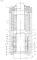
- a main shaft 3 of a main shaft device 1 in a machine tool is supported by a front-side bearing 4 and a rear-side bearing 5.
- the front-side bearing 4 is provided by a multi-row angular-contact ball bearing device which includes angular-contact ball bearings 41 through 44, each having a contact angle, arranged in back-to-back configuration at a front and a rear positions.
- Patent Literature 1 discloses an angular-contact ball bearing device of a four-row back-to-back configuration, as a multi-row angular-contact ball bearing device.
- the four-row back-to-back configuration angular-contact ball bearing device includes four rows of angular-contact ball bearings 41 through 44, with two of the rows disposed at a front position and the other two of the rows disposed at a rear position.
- contact angles ⁇ 1, ⁇ 2 of the front-position angular-contact ball bearings 41, 42 and contact angles ⁇ 3, ⁇ 4 of the rear-position angular-contact ball bearings 43, 44 are opposed to each other.
- Patent Literature 1 JP-A2011-52714 Gazette
- the four-row back-to-back configuration in Fig. 2 is changed to three-row back-to-back configuration as shown in Fig. 1 and the main shaft is shortened; or a new three-row back-to-back configuration is used for a newly designed main shaft.
- angular-contact ball bearings are combined in such a way that their contact angles are opposed to each other, and a preload is applied in order to achieve high-speed operation, high rigidity and high accuracy.
- the preload is balanced within bearing groups in which the contact angles are opposed to each other.
- the rear position which has a fewer number of rows (the one-row side of the three-row back-to-back configuration), i.e., the angular-contact ball bearing 43, is subjected to a larger load.
- Table 1 shows specifications of an actual bearing, in which the front-position angular-contact ball bearings 41, 42 have a maximum contact surface pressure (MPa) of 1600 while the rear-position angular-contact ball bearing 43 has a maximum contact surface pressure (MPa) 2000.
- a mainstream in the main shaft of machine tools is to use a built-in motor main shaft (a main shaft which has a motor within itself).
- the built-in motor is disposed near the small number of rows of angular-contact ball bearings at the rear position.
- the smaller number of rows of angular-contact ball bearings at the rear position and the built-in motor are placed at a closer distance from each other than before.
- the motor in the built-in motor main shaft generates heat.
- an object of the present invention is to provide a multi-row angular-contact ball bearing device in which angular-contact ball bearings each having a contact angle are arranged in back-to-back configuration in an array of three or a greater number of rows and the number of rows of the angular-contact ball bearings in a front position and the number of rows in a rear position are different from each other; and in which heat generation by the bearings in the smaller number of rows is reduced for prevention of burnout problems and extension of bearing life.
- the present invention provides a multi-row angular-contact ball bearing device comprising: angular-contact ball bearings, each having a contact angle, arranged in back-to-back configuration in an array of three or a greater number of rows, and the number of rows of the angular-contact ball bearings in a front position and the number of rows of the angular-contact ball bearings in a rear position are different from each other:
- the angular-contact ball bearings in a greater number of rows have their rolling elements made of steel
- the angular-contact ball bearings in a smaller number of rows have their rolling elements made of ceramic.
- the angular-contact ball bearings in a greater number of rows have their rolling elements of a diameter Da
- the angular-contact ball bearings in a smaller number of rows have their rolling elements of a diameter Da'
- the diameters have a relationship expressed as Da ⁇ Da' ⁇ 1.5 ⁇ Da.
- the angular-contact ball bearings in a smaller number of rows have a contact angle ⁇ '°
- the angular-contact ball bearings in a greater number of rows have a contact angle ⁇ °
- the contact angles have a relationship expressed as ⁇ ° ⁇ '° ⁇ ( ⁇ +30)°.
- the angular-contact ball bearings in a greater number of rows have their retainers made of a polyamide resin, and the angular-contact ball bearings in a smaller number of rows have their retainers made of a phenol or a PEEK resin.
- the rolling elements of the rear-position angular-contact ball bearing are provided by ceramic balls as in the present invention, it becomes possible to reduce heat generation and burnout problems because ceramic balls are light-weighted and have a smaller linear expansion coefficient as compared to steel balls.
- the rolling elements of the rear-position angular-contact ball bearing is provided by ceramic balls, and if the ceramic balls have its rolling element diameter Da' increased to not greater than one and a half times of a diameter Da of the rolling elements in the front-position angular-contact ball bearing (Da ⁇ Da' ⁇ 1.5 ⁇ Da), then the rear-position angular-contact ball bearing has an improved basic dynamic load rating, leading to extended life, reduced maximum contact surface pressure, reduced heat generation and prevention of burnout.
- a contact angle ⁇ ' of the rear-position angular-contact ball bearing is made greater than a contact angle ⁇ of a two-row side angular-contact ball bearing, i.e., if it has a relationship expressed as ⁇ ° ⁇ '° ⁇ ( ⁇ +30)°, it is possible to reduce heat generation and prevent burnout since the arrangement reduces a maximum contact surface pressure of the rear-position angular-contact ball bearing.
- the rear-position angular-contact ball bearing has its retainer made of a phenol resin or a PEEK resin which have superior heat tolerance, it becomes possible to prevent burnout.
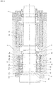
- a multi-row angular-contact ball bearing device is used, for example, as a front-side bearing of a main shaft 3 of a main shaft device 1 of a machine tool shown in Fig. 1 .
- the main shaft device 1 of the machine tool rotatably supports the main shaft 3 inside a bearing housing 2, with a front-side bearing 4 and a rear-side bearing 5, with a built-in motor 6 provided at an intermediate position in the main shaft 3 to give rotation drive to the main shaft 3.
- the front-side bearing 4 supports the main shaft 3 at its front end side, and is provided by a multi-row angular-contact ball bearing device.
- the rear-side bearing 5 supports the main shaft 3 at its rear end side, and is provided by a single-row angular-contact ball bearing in Fig. 1 .
- the front-side bearing 4 is provided by a three-row back-to-back configuration angular-contact ball bearing device in which three rows of angular-contact ball bearings 41, 42, 43 are grouped into two rows for a front position and one row for a rear position.
- the front-position angular-contact ball bearings 41, 42 have their contact angles ⁇ 1, ⁇ 2 opposed to a contact angle ⁇ 3 of the rear-position angular-contact ball bearing 43.
- the front-side bearing 4 which is provided by a multi-row angular-contact ball bearing device, has three inner rings 41a, 42a, 43a fastened and fixed to the main shaft 3 by tightening with an inner ring fixing nut 7, between a staged portion 3a of the main shaft 3 and the inner ring fixing nut 7.
- Outer rings 41b, 42b, 43b of the front-side bearing 4 are fixed at their respective positions by tightening with bolts of an outer ring holding lid 8, for example, between a stepped portion 2a of the bearing housing 2 and the outer ring holding lid 8.
- Inner ring spacers 19 and outer ring spacers 20 are placed between the angular-contact ball bearings 41, 42, 43 of the front-side bearing 4. By giving a difference in a width of the inner ring spacer 19 and that of the outer ring spacer 20, a fixed-portion preload is applied to the multi-row angular-contact ball bearing device.
- the built-in motor 6 includes a rotor 12 which is fixed to the main shaft 3; and a stator 13 which is provided on an inner circumference of the bearing housing 2 to face the rotor 12.
- the rear-position angular-contact ball bearing 43 in the smaller number of rows is subjected to a greater load, and thus the rear-position angular-contact ball bearing 43 in the smaller number of rows generates more heat than the front-position angular-contact ball bearings 41, 42 which are in the greater number of rows.
- the present invention provides the following arrangements to reduce heat generation by the angular-contact ball bearing 43 in the smaller number of rows, for burnout prevention and life extension.
- a first arrangement is, as shown in Table 2, that if the front-position angular-contact ball bearings 41, 42 use steel balls for their rolling elements, then the rear-position angular-contact ball bearing 43 uses ceramic balls for its rolling elements.
- the rolling element of the rear-position angular-contact ball bearing 43 is provided by a ceramic ball, and if the ceramic ball has a rolling element diameter Da' increased to one and a half time of the ceramic ball's rolling element diameter Da in Table 2 (Da ⁇ Da' ⁇ 1.5 ⁇ Da), then the single-row rear-position angular-contact ball bearing 43 has an improved basic dynamic load rating, leading to extended life, reduced maximum contact surface pressure, reduced heat generation and prevention of burnout.
- Table 6 shows an example in which the contact angle ⁇ 3 of the rear-position angular-contact ball bearing 43 is greater than the contact angles ⁇ 1, ⁇ 2 of the two-row angular-contact ball bearings 41, 42, i.e., ( ⁇ 1, ⁇ 2)° ⁇ 3° ⁇ [( ⁇ 1, ⁇ 2)+30]°.
- the rear-position angular-contact ball bearing 43 has a smaller maximum contact surface pressure than that in Table 1, so it is possible to reduce heat generation and prevent burnout.
Landscapes
- Engineering & Computer Science (AREA)
- General Engineering & Computer Science (AREA)
- Mechanical Engineering (AREA)
- Rolling Contact Bearings (AREA)
- Turning (AREA)
Abstract
Description
- The present invention relates to a multi-row angular-contact ball bearing device for use in supporting a machine tool main shaft.
- As shown in
Fig. 2 for example, amain shaft 3 of a main shaft device 1 in a machine tool is supported by a front-side bearing 4 and a rear-side bearing 5. - The front-side bearing 4 is provided by a multi-row angular-contact ball bearing device which includes angular-
contact ball bearings 41 through 44, each having a contact angle, arranged in back-to-back configuration at a front and a rear positions. - For example, Patent Literature 1 discloses an angular-contact ball bearing device of a four-row back-to-back configuration, as a multi-row angular-contact ball bearing device.
- As shown in
Fig. 2 , the four-row back-to-back configuration angular-contact ball bearing device includes four rows of angular-contact ball bearings 41 through 44, with two of the rows disposed at a front position and the other two of the rows disposed at a rear position. In this arrangement, contact angles α1, α2 of the front-position angular-contact ball bearings contact ball bearings - Patent Literature 1:
JP-A2011-52714 - In recent years, there is an increasing requirement for size reduction in the
main shaft 3 of the main shaft device 1 in a machine tool, in addition to high-speed operation, high rigidity and high accuracy. One solution to this is to reduce the number of rows of the angular-contact ball bearings used in themain shaft 3. - For example, the four-row back-to-back configuration in
Fig. 2 is changed to three-row back-to-back configuration as shown inFig. 1 and the main shaft is shortened; or a new three-row back-to-back configuration is used for a newly designed main shaft. - Typically in machine tool main shaft, angular-contact ball bearings are combined in such a way that their contact angles are opposed to each other, and a preload is applied in order to achieve high-speed operation, high rigidity and high accuracy. The preload is balanced within bearing groups in which the contact angles are opposed to each other. Like in the example of a three-row back-to-back configuration in
Fig. 1 , in the case where the number of rows of the angular-contact ball bearings 41 through 43 differs at a front position and a rear position, namely in the case where the front positon has two rows provided by the angular-contact ball bearings - As an example, Table 1 shows specifications of an actual bearing, in which the front-position angular-
contact ball bearings [Table 1] Bearing Array Front Position Rear Position Bearing 41 Bearing 42Bearing 43Contact Angle α1=15° α2=15° α3=15° Rolling Elementmaterial Steel Ball Steel Ball Steel Ball Rolling Element Diameter [Inch] 11/32 11/32 11/32 Number Of Rolling Elements [Quantity] 26 26 26 Amount Of Preload At Assembly [N] 200 200 400 Bearing Spring Constant (Axial) [N/Mm] 32.2 32.2 43.6 Basic Dynamic Load Rating [N] 22400 22400 22400 Maximum Contact Surface Pressure [Mpa] 1600 1600 2000 - As understood from Table 1, comparison in terms of maximum contact surface pressure between the rear-position angular-contact ball bearing 43 which has a smaller number of rows and the front-position angular-
contact ball bearings contact ball bearings contact ball bearings - Also, since the main shaft of a machine tool must be rigidly supported against machining loads exerted to the front position, it is typical that a greater number of rows of angular-contact ball bearings are disposed in the front position and a smaller number of rows of angular-contact ball bearings are disposed in the rear position.
- A mainstream in the main shaft of machine tools is to use a built-in motor main shaft (a main shaft which has a motor within itself). In this shaft, the built-in motor is disposed near the small number of rows of angular-contact ball bearings at the rear position. In recent years, due to the size reduction in machine tool main shafts, there is a trend that the smaller number of rows of angular-contact ball bearings at the rear position and the built-in motor are placed at a closer distance from each other than before.
- During operation, the motor in the built-in motor main shaft generates heat. This means that the smaller number of rows of angular-contact ball bearings at the rear position which are operating adjacently are subjected to heat, in addition to a large load they are subjected to. In other words, there is increased heat from a greater maximum contact surface pressure and there is additional heat from the motor, and these push up the temperature of bearings to a very critical range.
- Therefore, an object of the present invention is to provide a multi-row angular-contact ball bearing device in which angular-contact ball bearings each having a contact angle are arranged in back-to-back configuration in an array of three or a greater number of rows and the number of rows of the angular-contact ball bearings in a front position and the number of rows in a rear position are different from each other; and in which heat generation by the bearings in the smaller number of rows is reduced for prevention of burnout problems and extension of bearing life.
- In order to achieve the above-described object, the present invention provides a multi-row angular-contact ball bearing device comprising: angular-contact ball bearings, each having a contact angle, arranged in back-to-back configuration in an array of three or a greater number of rows, and the number of rows of the angular-contact ball bearings in a front position and the number of rows of the angular-contact ball bearings in a rear position are different from each other: In this arrangement, the angular-contact ball bearings in a greater number of rows have their rolling elements made of steel, and the angular-contact ball bearings in a smaller number of rows have their rolling elements made of ceramic.
- Also, the angular-contact ball bearings in a greater number of rows have their rolling elements of a diameter Da, the angular-contact ball bearings in a smaller number of rows have their rolling elements of a diameter Da', and the diameters have a relationship expressed as Da< Da'≤1.5·Da.
- Also, the angular-contact ball bearings in a smaller number of rows have a contact angle α'°, the angular-contact ball bearings in a greater number of rows have a contact angle α°, and the contact angles have a relationship expressed as α°<α'°≤(α+30)°.
- Also, the angular-contact ball bearings in a greater number of rows have their retainers made of a polyamide resin, and the angular-contact ball bearings in a smaller number of rows have their retainers made of a phenol or a PEEK resin.
- If the rolling elements of the rear-position angular-contact ball bearing are provided by ceramic balls as in the present invention, it becomes possible to reduce heat generation and burnout problems because ceramic balls are light-weighted and have a smaller linear expansion coefficient as compared to steel balls.
- Also, if the rolling elements of the rear-position angular-contact ball bearing is provided by ceramic balls, and if the ceramic balls have its rolling element diameter Da' increased to not greater than one and a half times of a diameter Da of the rolling elements in the front-position angular-contact ball bearing (Da<Da'≤1.5·Da), then the rear-position angular-contact ball bearing has an improved basic dynamic load rating, leading to extended life, reduced maximum contact surface pressure, reduced heat generation and prevention of burnout.
- Also, if a contact angle α' of the rear-position angular-contact ball bearing is made greater than a contact angle α of a two-row side angular-contact ball bearing, i.e., if it has a relationship expressed as α°<α'°≤(α+30)°, it is possible to reduce heat generation and prevent burnout since the arrangement reduces a maximum contact surface pressure of the rear-position angular-contact ball bearing.
- Also, if the rear-position angular-contact ball bearing has its retainer made of a phenol resin or a PEEK resin which have superior heat tolerance, it becomes possible to prevent burnout.
-
-
Fig. 1 is a sectional view of a machine tool's main shaft device having its front-side bearing provided by an angular-contact ball bearing device of a three-row back-to-back configuration. -
Fig. 2 is a sectional view of a machine tool's main shaft device having its front-side bearing provided by an angular-contact ball bearing device of a four-row back-to-back configuration. - Hereinafter, embodiments of the present invention will be described based on the attached drawings.
- A multi-row angular-contact ball bearing device according to the present invention is used, for example, as a front-side bearing of a
main shaft 3 of a main shaft device 1 of a machine tool shown inFig. 1 . - The main shaft device 1 of the machine tool rotatably supports the
main shaft 3 inside a bearinghousing 2, with a front-side bearing 4 and a rear-side bearing 5, with a built-inmotor 6 provided at an intermediate position in themain shaft 3 to give rotation drive to themain shaft 3. - The front-side bearing 4 supports the
main shaft 3 at its front end side, and is provided by a multi-row angular-contact ball bearing device. The rear-side bearing 5 supports themain shaft 3 at its rear end side, and is provided by a single-row angular-contact ball bearing inFig. 1 . - The front-side bearing 4 is provided by a three-row back-to-back configuration angular-contact ball bearing device in which three rows of angular-
contact ball bearings contact ball bearings - The front-side bearing 4, which is provided by a multi-row angular-contact ball bearing device, has three
inner rings main shaft 3 by tightening with an innerring fixing nut 7, between a stagedportion 3a of themain shaft 3 and the innerring fixing nut 7. -
Outer rings ring holding lid 8, for example, between astepped portion 2a of the bearinghousing 2 and the outerring holding lid 8. -
Inner ring spacers 19 andouter ring spacers 20 are placed between the angular-contact ball bearings inner ring spacer 19 and that of theouter ring spacer 20, a fixed-portion preload is applied to the multi-row angular-contact ball bearing device. - The built-in
motor 6 includes arotor 12 which is fixed to themain shaft 3; and astator 13 which is provided on an inner circumference of the bearinghousing 2 to face therotor 12. - In the case where the front position has two rows provided by the angular-
contact ball bearings contact ball bearings - A first arrangement is, as shown in Table 2, that if the front-position angular-
contact ball bearings - As understood from Table 2, if the rear-position angular-contact ball bearing 43 has its rolling elements provided by ceramic balls, their maximum contact surface pressure is the same as in the case of steel balls specified in Table 1, yet this reduces heat generation and leads to burnout prevention because ceramic balls are light-weighted and have a smaller linear expansion coefficient as compared to steel balls.
[Table 2] Bearing Array Front Position Rear Position Bearing 41 Bearing 42Bearing 43Contact Angle α1=15° α2=15° α3=15° Rolling Elementmaterial Steel Ball Steel Ball Ceramic Ball Rolling Element Diameter [Inch] 11/32 11/32 11/32 Number Of Rolling Elements [Quantity] 26 26 26 Amount Of Preload At Assembly [N] 200 200 400 Bearing Spring Constant (Axial) [N/Mm] 32.2 32.2 48.5 Basic Dynamic Load Rating [N] 22400 22400 22400 Maximum Contact Surface Pressure [Mpa] 1450 1450 2020 - Further, as understood from Table 3, if the rolling element of the rear-position angular-contact ball bearing 43 is provided by a ceramic ball, and if the ceramic ball has a rolling element diameter Da' increased to one and a half time of the ceramic ball's rolling element diameter Da in Table 2 (Da < Da' ≤ 1.5·Da), then the single-row rear-position angular-contact ball bearing 43 has an improved basic dynamic load rating, leading to extended life, reduced maximum contact surface pressure, reduced heat generation and prevention of burnout.
[Table 3] Bearing Array Front Position Rear Position Bearing 41 Bearing 42Bearing 43Contact Angle α1=15° α2=15° α3=15° Rolling Elementmaterial Steel Ball Steel Ball Ceramic Ball Rolling Element Diameter [Inch] 11/32 11/32 1/2 Number Of Rolling Elements [Quantity] 26 26 24 Amount Of Preload At Assembly [N] 200 200 400 Bearing Spring Constant (Axial) [N/Mm] 32.2 32.2 50.0 Basic Dynamic Load Rating [N] 22400 22400 45000 Maximum Contact Surface Pressure [Mpa] 1490 1490 1690 - Furthermore, Tables 4 and 5 show cases where Da'>1.5·Da, and Da'=1.8·Da. While it seems that these arrangements will brings benefits similar to those provided by the arrangement in Table 3, it turned out that in the range given by Table 4 and Table 5, Da' becomes much greater than Da; that in order for Da' to fit within the bearing space, there is an upper limit to its size; and as a result, Da must be decreased. For these reasons, settings in Table 4 or Table 5 reduce the load rating and/or increase the maximum contact surface pressure of the two-row angular-
contact ball bearings [Table 4] Bearing Array Front Position Rear Position Bearing 41 Bearing 42Bearing 43Contact Angle α1=15° α2=15° α3=15° Rolling Elementmaterial Steel Ball Steel Ball Ceramic Ball Rolling Element Diameter [Inch] 11/32 11/32 5/8 Number Of Rolling Elements [Quantity] 26 26 22 Amount Of Preload At Assembly [N] 200 200 400 Bearing Spring Constant (Axial) [N/Mm] 32.2 32.2 51.2 Basic Dynamic Load Rating [N] 22400 22400 65500 Maximum Contact Surface Pressure [Mpa] 1320 1320 1520 [Table 5] Bearing Array Front Position Rear Position Bearing 41 Bearing 42Bearing 43Contact Angle α1=15° α2=15° α3=15° Rolling Elementmaterial Steel Ball Steel Ball Ceramic Ball Rolling Element Diameter [Inch] 9/32 9/32 5/8 Number Of Rolling Elements [Quantity] 26 26 22 Amount Of Preload At Assembly [N] 200 200 400 Bearing Spring Constant (Axial) [N/Mm] 32.2 32.2 51.2 Basic Dynamic Load Rating [N] 14800 14800 65500 Maximum Contact Surface Pressure [Mpa] 1700 1700 1500 - Next, Table 6 shows an example in which the contact angle α3 of the rear-position angular-
contact ball bearing 43 is greater than the contact angles α1, α2 of the two-row angular-contact ball bearings contact ball bearing 43 has a smaller maximum contact surface pressure than that in Table 1, so it is possible to reduce heat generation and prevent burnout.[Table 6] Bearing Array Front Position Rear Position Bearing 41 Bearing 42Bearing 43Contact Angle α1=15° α2=15° α3=25° Rolling Elementmaterial Steel Ball Steel Ball Ceramic Ball Rolling Element Diameter [Inch] 11/32 11/32 11/32 Number Of Rolling Elements [Quantity] 26 26 26 Amount Of Preload At Assembly [N] 200 200 400 Bearing Spring Constant (Axial) [N/Mm] 32.2 32.2 103.5 Basic Dynamic Load Rating [N] 22400 22400 21100 Maximum Contact Surface Pressure [Mpa] 1540 1540 1850 - In a conventional angular-contact ball bearing, it is typical to use an injection-molded retainer of a polyamide resin for its cost advantages. However, in cases where the bearing is subjected to a large load and thermal influence due to heat generation by the nearby built-in motor as is the present rear-position angular-contact ball bearing, using a retainer which is made of phenol resin or PEEK resin makes it possible to prevent burnout.
-
- 1 :
- Main Shaft Device
- 2 :
- Bearing Housing
- 3 :
- Main Shaft
- 4 :
- Front-Side Bearing
- 5 :
- Rear-Side Bearing
- 41, 42, 43 :
- Angular-contact ball bearing
- Da, Da' :
- Rolling Element Diameter
- α1 -α3 :
- Contact Angle
Claims (5)
- A multi-row angular-contact ball bearing device comprising: angular-contact ball bearings, each having a contact angle, arranged in back-to-back configuration in an array of three or a greater number of rows, the number of rows of the angular-contact ball bearings in a front position and the number of rows of the angular-contact ball bearings in a rear position being different from each other, wherein the angular-contact ball bearings in a greater number of rows have their rolling elements made of steel, and the angular-contact ball bearings in a smaller number of rows have their rolling elements made of ceramic.
- A multi-row angular-contact ball bearing device comprising: angular-contact ball bearings, each having a contact angle, arranged in back-to-back configuration in an array of three or a greater number of rows, the number of rows of the angular-contact ball bearings in a front position and the number of rows of the angular-contact ball bearings in a rear position being different from each other, wherein the angular-contact ball bearings in a greater number of rows have their rolling elements of a diameter Da, the angular-contact ball bearings in a smaller number of rows have their rolling elements of a diameter Da', and the diameters have a relationship expressed as Da<Da'≤1.5·Da.
- A multi-row angular-contact ball bearing device comprising: angular-contact ball bearings, each having a contact angle, arranged in back-to-back configuration in an array of three or a greater number of rows, the number of rows of the angular-contact ball bearings in a front position and the number of rows of the angular-contact ball bearings in a rear position being different from each other, wherein the angular-contact ball bearings in a smaller number of rows have their contact angle of α'°, the angular-contact ball bearings in a greater number of rows having their contact angle of α°, and the contact angles have a relationship expressed as α°< α'°≤(α+30)°.
- A multi-row angular-contact ball bearing device comprising: angular-contact ball bearings, each having a contact angle, arranged in back-to-back configuration in an array of three or a greater number of rows, the number of rows of the angular-contact ball bearings in a front position and the number of rows of the angular-contact ball bearings in a rear position being different from each other, wherein the angular-contact ball bearings in a greater number of rows have their retainers made of a polyamide resin, and the angular-contact ball bearings in a smaller number of rows have their retainers made of a phenol or a PEEK resin.
- A bearing device for a machine tool main shaft, wherein the bearing device uses the multi-row angular-contact ball bearing devices according to one of Claim 1 through 4 for a front-side bearing of the main shaft.
Applications Claiming Priority (2)
| Application Number | Priority Date | Filing Date | Title |
|---|---|---|---|
| JP2016111445A JP6978188B2 (en) | 2016-06-03 | 2016-06-03 | Multi-row combination angular contact ball bearing device |
| PCT/JP2017/017375 WO2017208731A1 (en) | 2016-06-03 | 2017-05-08 | Multi-row combination angular contact ball bearing device |
Publications (3)
| Publication Number | Publication Date |
|---|---|
| EP3467327A1 true EP3467327A1 (en) | 2019-04-10 |
| EP3467327A4 EP3467327A4 (en) | 2020-01-01 |
| EP3467327B1 EP3467327B1 (en) | 2021-03-10 |
Family
ID=60479509
Family Applications (1)
| Application Number | Title | Priority Date | Filing Date |
|---|---|---|---|
| EP17806290.7A Not-in-force EP3467327B1 (en) | 2016-06-03 | 2017-05-08 | Multi-row combination angular contact ball bearing device |
Country Status (6)
| Country | Link |
|---|---|
| EP (1) | EP3467327B1 (en) |
| JP (1) | JP6978188B2 (en) |
| KR (1) | KR20190015274A (en) |
| CN (1) | CN109219708B (en) |
| TW (1) | TWI709695B (en) |
| WO (1) | WO2017208731A1 (en) |
Cited By (1)
| Publication number | Priority date | Publication date | Assignee | Title |
|---|---|---|---|---|
| FR3101596A1 (en) * | 2019-10-08 | 2021-04-09 | Alstom Transport Technologies | Motor and / or generator for a rail vehicle, associated bogie and rail vehicle |
Families Citing this family (2)
| Publication number | Priority date | Publication date | Assignee | Title |
|---|---|---|---|---|
| JPWO2021085635A1 (en) * | 2019-10-30 | 2021-05-06 | ||
| USD1017784S1 (en) | 2021-10-27 | 2024-03-12 | Samsung Electronics Co., Ltd. | Air conditioner |
Family Cites Families (13)
| Publication number | Priority date | Publication date | Assignee | Title |
|---|---|---|---|---|
| JPH04248021A (en) * | 1991-01-23 | 1992-09-03 | Ntn Corp | Holder for rolling bearing |
| JPH1043909A (en) * | 1996-07-30 | 1998-02-17 | Nippon Seiko Kk | Rotating body drive |
| US6481898B1 (en) * | 1998-01-20 | 2002-11-19 | Nsk Ltd. | Ball bearing |
| US6994474B2 (en) * | 2001-05-29 | 2006-02-07 | Nsk Ltd. | Rolling sliding member and rolling apparatus |
| CN2671722Y (en) * | 2004-02-19 | 2005-01-19 | 应圣平 | Support mechanism of common high speed digital control lathe main shaft |
| JP2005299761A (en) * | 2004-04-09 | 2005-10-27 | Nsk Ltd | Multi-row ball bearing |
| TW200712349A (en) * | 2005-04-27 | 2007-04-01 | Ntn Toyo Bearing Co Ltd | Bearing assembly |
| JP2006307912A (en) * | 2005-04-27 | 2006-11-09 | Ntn Corp | Rolling bearing |
| JP2006326695A (en) * | 2005-05-23 | 2006-12-07 | Ntn Corp | Bearing device for main spindle of machine tool |
| US8360653B2 (en) * | 2007-05-11 | 2013-01-29 | Schaeffler Technologies AG & Co. KG | Double row, angular contact ball bearing with two plastic comb cages with retaining tabs |
| JP5724918B2 (en) * | 2012-03-21 | 2015-05-27 | 大豊工業株式会社 | Plain bearing |
| JP2013194886A (en) * | 2012-03-22 | 2013-09-30 | Nsk Ltd | Bearing device and rotating body |
| JP2014020481A (en) * | 2012-07-19 | 2014-02-03 | Nsk Ltd | Angular contact ball bearing |
-
2016
- 2016-06-03 JP JP2016111445A patent/JP6978188B2/en active Active
-
2017
- 2017-05-05 TW TW106114968A patent/TWI709695B/en not_active IP Right Cessation
- 2017-05-08 WO PCT/JP2017/017375 patent/WO2017208731A1/en not_active Ceased
- 2017-05-08 CN CN201780034305.6A patent/CN109219708B/en not_active Expired - Fee Related
- 2017-05-08 KR KR1020187034902A patent/KR20190015274A/en not_active Ceased
- 2017-05-08 EP EP17806290.7A patent/EP3467327B1/en not_active Not-in-force
Cited By (4)
| Publication number | Priority date | Publication date | Assignee | Title |
|---|---|---|---|---|
| FR3101596A1 (en) * | 2019-10-08 | 2021-04-09 | Alstom Transport Technologies | Motor and / or generator for a rail vehicle, associated bogie and rail vehicle |
| CN112622941A (en) * | 2019-10-08 | 2021-04-09 | 阿尔斯通运输科技公司 | Engine and/or generator for a railway vehicle, associated bogie and railway vehicle |
| EP3805583A1 (en) * | 2019-10-08 | 2021-04-14 | ALSTOM Transport Technologies | Engine and/or generator for a railway vehicle, associated bogie and railway vehicle |
| CN112622941B (en) * | 2019-10-08 | 2024-11-01 | 阿尔斯通运输科技公司 | Engine and/or generator for a railway vehicle, associated bogie and railway vehicle |
Also Published As
| Publication number | Publication date |
|---|---|
| EP3467327A4 (en) | 2020-01-01 |
| TWI709695B (en) | 2020-11-11 |
| TW201742991A (en) | 2017-12-16 |
| EP3467327B1 (en) | 2021-03-10 |
| CN109219708B (en) | 2020-07-28 |
| WO2017208731A1 (en) | 2017-12-07 |
| CN109219708A (en) | 2019-01-15 |
| KR20190015274A (en) | 2019-02-13 |
| JP6978188B2 (en) | 2021-12-08 |
| JP2017219053A (en) | 2017-12-14 |
Similar Documents
| Publication | Publication Date | Title |
|---|---|---|
| US8523453B2 (en) | Multiple-row large roller bearing, especially axial radial bearing for the main arrangement of bearings of the rotor shaft of a wind power installation | |
| EP3467327B1 (en) | Multi-row combination angular contact ball bearing device | |
| JP2014152788A (en) | Rolling bearing | |
| KR20170124562A (en) | Spindle device | |
| CN106104028A (en) | Turntable bearing unit | |
| KR102593405B1 (en) | Cam device | |
| JP5704213B2 (en) | Bearing device | |
| CN102472315A (en) | Compact radial-axial bearing | |
| CN101133255A (en) | High-speed floating bearings, especially for supporting spindles of machine tools | |
| EP2784339B1 (en) | Rolling bearing comprising at least one multi-part ring, notably for a wind turbine | |
| KR102026075B1 (en) | Combination ball bearing and main shaft device for machine tool | |
| TWI680029B (en) | Main spindle device | |
| US8596874B2 (en) | Bearing in irregular shaped housings | |
| ES2256486T3 (en) | PROCEDURE TO FORM A BEARING ASSEMBLY WITH ROLLERS WITH ICOS. | |
| JP5453764B2 (en) | Bearing device and assembly method thereof | |
| JP2006322496A (en) | Multi-row angular ball bearing | |
| EP0426279A2 (en) | Hollow roller bearing and method of making and mounting same | |
| JP2006326695A (en) | Bearing device for main spindle of machine tool | |
| JP2003336640A (en) | Multi-point contact ball bearing | |
| CN113423961B (en) | Bearing structure | |
| JPH11294554A (en) | Lead screw device | |
| JP2008101631A (en) | Rolling bearing with seal | |
| JP2023013087A (en) | rolling bearing | |
| US8585297B2 (en) | Apparatus with rolling bearing having a sleeve | |
| JP4326533B2 (en) | Combined rolling bearing |
Legal Events
| Date | Code | Title | Description |
|---|---|---|---|
| STAA | Information on the status of an ep patent application or granted ep patent |
Free format text: STATUS: THE INTERNATIONAL PUBLICATION HAS BEEN MADE |
|
| PUAI | Public reference made under article 153(3) epc to a published international application that has entered the european phase |
Free format text: ORIGINAL CODE: 0009012 |
|
| STAA | Information on the status of an ep patent application or granted ep patent |
Free format text: STATUS: REQUEST FOR EXAMINATION WAS MADE |
|
| 17P | Request for examination filed |
Effective date: 20181228 |
|
| AK | Designated contracting states |
Kind code of ref document: A1 Designated state(s): AL AT BE BG CH CY CZ DE DK EE ES FI FR GB GR HR HU IE IS IT LI LT LU LV MC MK MT NL NO PL PT RO RS SE SI SK SM TR |
|
| AX | Request for extension of the european patent |
Extension state: BA ME |
|
| DAV | Request for validation of the european patent (deleted) | ||
| DAX | Request for extension of the european patent (deleted) | ||
| A4 | Supplementary search report drawn up and despatched |
Effective date: 20191129 |
|
| RIC1 | Information provided on ipc code assigned before grant |
Ipc: F16C 19/54 20060101ALI20191125BHEP Ipc: F16C 33/32 20060101ALI20191125BHEP Ipc: F16C 19/56 20060101ALI20191125BHEP Ipc: F16C 19/18 20060101AFI20191125BHEP Ipc: F16C 33/44 20060101ALI20191125BHEP Ipc: B23B 19/02 20060101ALI20191125BHEP |
|
| GRAP | Despatch of communication of intention to grant a patent |
Free format text: ORIGINAL CODE: EPIDOSNIGR1 |
|
| STAA | Information on the status of an ep patent application or granted ep patent |
Free format text: STATUS: GRANT OF PATENT IS INTENDED |
|
| RIC1 | Information provided on ipc code assigned before grant |
Ipc: F16C 33/44 20060101ALI20201105BHEP Ipc: F16C 33/32 20060101ALI20201105BHEP Ipc: F16C 19/54 20060101ALI20201105BHEP Ipc: F16C 19/56 20060101ALI20201105BHEP Ipc: F16C 19/18 20060101AFI20201105BHEP Ipc: B23B 19/02 20060101ALI20201105BHEP |
|
| INTG | Intention to grant announced |
Effective date: 20201204 |
|
| GRAS | Grant fee paid |
Free format text: ORIGINAL CODE: EPIDOSNIGR3 |
|
| GRAA | (expected) grant |
Free format text: ORIGINAL CODE: 0009210 |
|
| STAA | Information on the status of an ep patent application or granted ep patent |
Free format text: STATUS: THE PATENT HAS BEEN GRANTED |
|
| AK | Designated contracting states |
Kind code of ref document: B1 Designated state(s): AL AT BE BG CH CY CZ DE DK EE ES FI FR GB GR HR HU IE IS IT LI LT LU LV MC MK MT NL NO PL PT RO RS SE SI SK SM TR |
|
| REG | Reference to a national code |
Ref country code: GB Ref legal event code: FG4D |
|
| REG | Reference to a national code |
Ref country code: AT Ref legal event code: REF Ref document number: 1370115 Country of ref document: AT Kind code of ref document: T Effective date: 20210315 Ref country code: CH Ref legal event code: EP |
|
| REG | Reference to a national code |
Ref country code: IE Ref legal event code: FG4D |
|
| REG | Reference to a national code |
Ref country code: DE Ref legal event code: R096 Ref document number: 602017034455 Country of ref document: DE |
|
| REG | Reference to a national code |
Ref country code: LT Ref legal event code: MG9D |
|
| PG25 | Lapsed in a contracting state [announced via postgrant information from national office to epo] |
Ref country code: NO Free format text: LAPSE BECAUSE OF FAILURE TO SUBMIT A TRANSLATION OF THE DESCRIPTION OR TO PAY THE FEE WITHIN THE PRESCRIBED TIME-LIMIT Effective date: 20210610 Ref country code: GR Free format text: LAPSE BECAUSE OF FAILURE TO SUBMIT A TRANSLATION OF THE DESCRIPTION OR TO PAY THE FEE WITHIN THE PRESCRIBED TIME-LIMIT Effective date: 20210611 Ref country code: FI Free format text: LAPSE BECAUSE OF FAILURE TO SUBMIT A TRANSLATION OF THE DESCRIPTION OR TO PAY THE FEE WITHIN THE PRESCRIBED TIME-LIMIT Effective date: 20210310 Ref country code: HR Free format text: LAPSE BECAUSE OF FAILURE TO SUBMIT A TRANSLATION OF THE DESCRIPTION OR TO PAY THE FEE WITHIN THE PRESCRIBED TIME-LIMIT Effective date: 20210310 Ref country code: BG Free format text: LAPSE BECAUSE OF FAILURE TO SUBMIT A TRANSLATION OF THE DESCRIPTION OR TO PAY THE FEE WITHIN THE PRESCRIBED TIME-LIMIT Effective date: 20210610 Ref country code: LT Free format text: LAPSE BECAUSE OF FAILURE TO SUBMIT A TRANSLATION OF THE DESCRIPTION OR TO PAY THE FEE WITHIN THE PRESCRIBED TIME-LIMIT Effective date: 20210310 |
|
| PGFP | Annual fee paid to national office [announced via postgrant information from national office to epo] |
Ref country code: IT Payment date: 20210531 Year of fee payment: 5 Ref country code: DE Payment date: 20210520 Year of fee payment: 5 |
|
| REG | Reference to a national code |
Ref country code: AT Ref legal event code: MK05 Ref document number: 1370115 Country of ref document: AT Kind code of ref document: T Effective date: 20210310 |
|
| REG | Reference to a national code |
Ref country code: NL Ref legal event code: MP Effective date: 20210310 |
|
| PG25 | Lapsed in a contracting state [announced via postgrant information from national office to epo] |
Ref country code: SE Free format text: LAPSE BECAUSE OF FAILURE TO SUBMIT A TRANSLATION OF THE DESCRIPTION OR TO PAY THE FEE WITHIN THE PRESCRIBED TIME-LIMIT Effective date: 20210310 Ref country code: LV Free format text: LAPSE BECAUSE OF FAILURE TO SUBMIT A TRANSLATION OF THE DESCRIPTION OR TO PAY THE FEE WITHIN THE PRESCRIBED TIME-LIMIT Effective date: 20210310 Ref country code: RS Free format text: LAPSE BECAUSE OF FAILURE TO SUBMIT A TRANSLATION OF THE DESCRIPTION OR TO PAY THE FEE WITHIN THE PRESCRIBED TIME-LIMIT Effective date: 20210310 |
|
| PG25 | Lapsed in a contracting state [announced via postgrant information from national office to epo] |
Ref country code: NL Free format text: LAPSE BECAUSE OF FAILURE TO SUBMIT A TRANSLATION OF THE DESCRIPTION OR TO PAY THE FEE WITHIN THE PRESCRIBED TIME-LIMIT Effective date: 20210310 |
|
| PG25 | Lapsed in a contracting state [announced via postgrant information from national office to epo] |
Ref country code: CZ Free format text: LAPSE BECAUSE OF FAILURE TO SUBMIT A TRANSLATION OF THE DESCRIPTION OR TO PAY THE FEE WITHIN THE PRESCRIBED TIME-LIMIT Effective date: 20210310 Ref country code: EE Free format text: LAPSE BECAUSE OF FAILURE TO SUBMIT A TRANSLATION OF THE DESCRIPTION OR TO PAY THE FEE WITHIN THE PRESCRIBED TIME-LIMIT Effective date: 20210310 Ref country code: AT Free format text: LAPSE BECAUSE OF FAILURE TO SUBMIT A TRANSLATION OF THE DESCRIPTION OR TO PAY THE FEE WITHIN THE PRESCRIBED TIME-LIMIT Effective date: 20210310 Ref country code: SM Free format text: LAPSE BECAUSE OF FAILURE TO SUBMIT A TRANSLATION OF THE DESCRIPTION OR TO PAY THE FEE WITHIN THE PRESCRIBED TIME-LIMIT Effective date: 20210310 |
|
| PG25 | Lapsed in a contracting state [announced via postgrant information from national office to epo] |
Ref country code: IS Free format text: LAPSE BECAUSE OF FAILURE TO SUBMIT A TRANSLATION OF THE DESCRIPTION OR TO PAY THE FEE WITHIN THE PRESCRIBED TIME-LIMIT Effective date: 20210710 Ref country code: PL Free format text: LAPSE BECAUSE OF FAILURE TO SUBMIT A TRANSLATION OF THE DESCRIPTION OR TO PAY THE FEE WITHIN THE PRESCRIBED TIME-LIMIT Effective date: 20210310 Ref country code: PT Free format text: LAPSE BECAUSE OF FAILURE TO SUBMIT A TRANSLATION OF THE DESCRIPTION OR TO PAY THE FEE WITHIN THE PRESCRIBED TIME-LIMIT Effective date: 20210712 Ref country code: SK Free format text: LAPSE BECAUSE OF FAILURE TO SUBMIT A TRANSLATION OF THE DESCRIPTION OR TO PAY THE FEE WITHIN THE PRESCRIBED TIME-LIMIT Effective date: 20210310 Ref country code: RO Free format text: LAPSE BECAUSE OF FAILURE TO SUBMIT A TRANSLATION OF THE DESCRIPTION OR TO PAY THE FEE WITHIN THE PRESCRIBED TIME-LIMIT Effective date: 20210310 |
|
| REG | Reference to a national code |
Ref country code: DE Ref legal event code: R097 Ref document number: 602017034455 Country of ref document: DE |
|
| REG | Reference to a national code |
Ref country code: CH Ref legal event code: PL |
|
| PLBE | No opposition filed within time limit |
Free format text: ORIGINAL CODE: 0009261 |
|
| STAA | Information on the status of an ep patent application or granted ep patent |
Free format text: STATUS: NO OPPOSITION FILED WITHIN TIME LIMIT |
|
| PG25 | Lapsed in a contracting state [announced via postgrant information from national office to epo] |
Ref country code: ES Free format text: LAPSE BECAUSE OF FAILURE TO SUBMIT A TRANSLATION OF THE DESCRIPTION OR TO PAY THE FEE WITHIN THE PRESCRIBED TIME-LIMIT Effective date: 20210310 Ref country code: CH Free format text: LAPSE BECAUSE OF NON-PAYMENT OF DUE FEES Effective date: 20210531 Ref country code: DK Free format text: LAPSE BECAUSE OF FAILURE TO SUBMIT A TRANSLATION OF THE DESCRIPTION OR TO PAY THE FEE WITHIN THE PRESCRIBED TIME-LIMIT Effective date: 20210310 Ref country code: AL Free format text: LAPSE BECAUSE OF FAILURE TO SUBMIT A TRANSLATION OF THE DESCRIPTION OR TO PAY THE FEE WITHIN THE PRESCRIBED TIME-LIMIT Effective date: 20210310 Ref country code: MC Free format text: LAPSE BECAUSE OF FAILURE TO SUBMIT A TRANSLATION OF THE DESCRIPTION OR TO PAY THE FEE WITHIN THE PRESCRIBED TIME-LIMIT Effective date: 20210310 Ref country code: LU Free format text: LAPSE BECAUSE OF NON-PAYMENT OF DUE FEES Effective date: 20210508 Ref country code: LI Free format text: LAPSE BECAUSE OF NON-PAYMENT OF DUE FEES Effective date: 20210531 |
|
| REG | Reference to a national code |
Ref country code: BE Ref legal event code: MM Effective date: 20210531 |
|
| 26N | No opposition filed |
Effective date: 20211213 |
|
| GBPC | Gb: european patent ceased through non-payment of renewal fee |
Effective date: 20210610 |
|
| PG25 | Lapsed in a contracting state [announced via postgrant information from national office to epo] |
Ref country code: SI Free format text: LAPSE BECAUSE OF FAILURE TO SUBMIT A TRANSLATION OF THE DESCRIPTION OR TO PAY THE FEE WITHIN THE PRESCRIBED TIME-LIMIT Effective date: 20210310 |
|
| PG25 | Lapsed in a contracting state [announced via postgrant information from national office to epo] |
Ref country code: IE Free format text: LAPSE BECAUSE OF NON-PAYMENT OF DUE FEES Effective date: 20210508 Ref country code: GB Free format text: LAPSE BECAUSE OF NON-PAYMENT OF DUE FEES Effective date: 20210610 |
|
| PG25 | Lapsed in a contracting state [announced via postgrant information from national office to epo] |
Ref country code: IS Free format text: LAPSE BECAUSE OF FAILURE TO SUBMIT A TRANSLATION OF THE DESCRIPTION OR TO PAY THE FEE WITHIN THE PRESCRIBED TIME-LIMIT Effective date: 20210710 Ref country code: FR Free format text: LAPSE BECAUSE OF NON-PAYMENT OF DUE FEES Effective date: 20210510 |
|
| PG25 | Lapsed in a contracting state [announced via postgrant information from national office to epo] |
Ref country code: BE Free format text: LAPSE BECAUSE OF NON-PAYMENT OF DUE FEES Effective date: 20210531 |
|
| REG | Reference to a national code |
Ref country code: DE Ref legal event code: R119 Ref document number: 602017034455 Country of ref document: DE |
|
| PG25 | Lapsed in a contracting state [announced via postgrant information from national office to epo] |
Ref country code: DE Free format text: LAPSE BECAUSE OF NON-PAYMENT OF DUE FEES Effective date: 20221201 |
|
| PG25 | Lapsed in a contracting state [announced via postgrant information from national office to epo] |
Ref country code: CY Free format text: LAPSE BECAUSE OF FAILURE TO SUBMIT A TRANSLATION OF THE DESCRIPTION OR TO PAY THE FEE WITHIN THE PRESCRIBED TIME-LIMIT Effective date: 20210310 |
|
| PG25 | Lapsed in a contracting state [announced via postgrant information from national office to epo] |
Ref country code: IT Free format text: LAPSE BECAUSE OF NON-PAYMENT OF DUE FEES Effective date: 20220508 Ref country code: HU Free format text: LAPSE BECAUSE OF FAILURE TO SUBMIT A TRANSLATION OF THE DESCRIPTION OR TO PAY THE FEE WITHIN THE PRESCRIBED TIME-LIMIT; INVALID AB INITIO Effective date: 20170508 |
|
| PG25 | Lapsed in a contracting state [announced via postgrant information from national office to epo] |
Ref country code: MK Free format text: LAPSE BECAUSE OF FAILURE TO SUBMIT A TRANSLATION OF THE DESCRIPTION OR TO PAY THE FEE WITHIN THE PRESCRIBED TIME-LIMIT Effective date: 20210310 |
|
| PG25 | Lapsed in a contracting state [announced via postgrant information from national office to epo] |
Ref country code: TR Free format text: LAPSE BECAUSE OF FAILURE TO SUBMIT A TRANSLATION OF THE DESCRIPTION OR TO PAY THE FEE WITHIN THE PRESCRIBED TIME-LIMIT Effective date: 20210310 |
|
| PG25 | Lapsed in a contracting state [announced via postgrant information from national office to epo] |
Ref country code: MT Free format text: LAPSE BECAUSE OF FAILURE TO SUBMIT A TRANSLATION OF THE DESCRIPTION OR TO PAY THE FEE WITHIN THE PRESCRIBED TIME-LIMIT Effective date: 20210310 |