EP3467183A1 - Compact metering system - Google Patents
Compact metering system Download PDFInfo
- Publication number
- EP3467183A1 EP3467183A1 EP18209724.6A EP18209724A EP3467183A1 EP 3467183 A1 EP3467183 A1 EP 3467183A1 EP 18209724 A EP18209724 A EP 18209724A EP 3467183 A1 EP3467183 A1 EP 3467183A1
- Authority
- EP
- European Patent Office
- Prior art keywords
- cleaning
- medium
- dosing
- cleaning device
- laundry
- Prior art date
- Legal status (The legal status is an assumption and is not a legal conclusion. Google has not performed a legal analysis and makes no representation as to the accuracy of the status listed.)
- Granted
Links
Images

Classifications
-
- D—TEXTILES; PAPER
- D06—TREATMENT OF TEXTILES OR THE LIKE; LAUNDERING; FLEXIBLE MATERIALS NOT OTHERWISE PROVIDED FOR
- D06F—LAUNDERING, DRYING, IRONING, PRESSING OR FOLDING TEXTILE ARTICLES
- D06F39/00—Details of washing machines not specific to a single type of machines covered by groups D06F9/00 - D06F27/00
- D06F39/02—Devices for adding soap or other washing agents
- D06F39/022—Devices for adding soap or other washing agents in a liquid state
-
- A—HUMAN NECESSITIES
- A47—FURNITURE; DOMESTIC ARTICLES OR APPLIANCES; COFFEE MILLS; SPICE MILLS; SUCTION CLEANERS IN GENERAL
- A47L—DOMESTIC WASHING OR CLEANING; SUCTION CLEANERS IN GENERAL
- A47L15/00—Washing or rinsing machines for crockery or tableware
-
- A—HUMAN NECESSITIES
- A47—FURNITURE; DOMESTIC ARTICLES OR APPLIANCES; COFFEE MILLS; SPICE MILLS; SUCTION CLEANERS IN GENERAL
- A47L—DOMESTIC WASHING OR CLEANING; SUCTION CLEANERS IN GENERAL
- A47L15/00—Washing or rinsing machines for crockery or tableware
- A47L15/0018—Controlling processes, i.e. processes to control the operation of the machine characterised by the purpose or target of the control
Definitions
- the invention relates to a method for alternately supplying a flushing medium and at least one cleaning medium by means of a metering for at least one laundry cleaning device, wherein the metering is supplied to the flushing medium via a connected to at least one inlet connection Spülmediumszu effet, and the metering with each laundry cleaning device via a respective Waschmediumszu effet with a Output terminal is connected.
- the invention relates to a cleaning device for carrying out the method according to the invention.
- Dosing systems for laundry cleaning devices have become known from the prior art, wherein each laundry cleaning device is assigned in each case a metering. If a user has several laundry cleaning devices, this has the consequence that several dosing systems must be provided.
- the dosing meet the purpose of supplying a flushing medium and usually several different cleaning media of the respective laundry cleaning device in a defined order.
- the metering at least two supply lines, which are connected to a laundry cleaning device, namely a Spülmediumszutechnisch and at least one cleaning medium supply line.
- the cleaning medium is usually pumped by a pump to the laundry cleaning device.
- Peristaltic pumps are frequently used for this purpose, which mechanically stress the cleaning medium feed line designed as a hose and therefore require the most flexible hoses possible for reliable operation.
- Detergents that achieve the desired cleaning effect often have the unpleasant side effect of changing the composition of the tubing and thus reducing their service life. This leads to shortened maintenance intervals and to rising operating costs or at worst to a leakage of the supply lines and as a result to a total failure of the laundry cleaning device. Since a plurality of cleaning media is usually used in a washing process, and the cleaning media must be supplied separately from each other in order to avoid undesirable reactions between the cleaning media, in practice, several cleaning medium supply lines be provided with one pump. The variety of these leads not only represents a considerable installation and cost, but also increases the risk of failure of the laundry cleaning device or dosing.
- the method according to the invention it is possible to supply a laundry cleaning device by means of a single washing medium supply line, which takes over both the supply of the flushing medium and the at least one cleaning medium from the metering to the laundry cleaning device.
- the number of lines that connect the dosing with the laundry cleaning device can be significantly reduced.
- the service life of the washing medium supply line is significantly higher than that of an equivalent cleaning medium supply line, since cleaning media dwell only in the dosing system and the washing medium supply line during the period in which the laundry cleaning device is supplied with a cleaning medium.
- the subsequent rinsing with the rinsing medium which is preferably water, increases the life of the dosing and the Waschmediumszutechnisch considerably.
- the cleaning medium is preferably in step d) with the rinsing medium mixed, whereby the cleaning medium passes only in dilute form in the washing medium supply line.
- the life of the washing medium supply line can be additionally increased.
- the detection of the cleaning job can be done via a user interface such as a user terminal that can be located on the dosing.
- a cleaning order can also be transferred from external devices to the dosing system.
- the dosing system can automatically generate jobs in a manner that can be predetermined by the user.
- a cleaning job preferably contains the cleaning parameters in which the quantity and the sequence of the media to be supplied to the laundry cleaning device are fixed. Also, the exposure time, the cleaning temperature or the speed of a washing drum can be specified.
- Rinsing the dosing system in step e) additionally increases the service life of the dosing system or components provided therein, for example, by preventing sticking of mechanically moved or stressed parts.
- the rinsing process is usually ended by closing at least one participating connection (input connection and / or output connection).
- each input port has an input valve and each output port has an output valve, wherein at least one input valve and the output valve associated with the laundry cleaning device according to step c), depending on the result, from the test in step b) Step c) are opened, wherein after or during step c) a respective cleaning medium associated with a cleaning medium valve is opened for a predetermined period of time, and before step e) the opened cleaning medium valve is closed again, wherein the rinsing step e) in a after Step e) takes place step f) by closing the respective output valve and / or the input valves is terminated.
- the execution of said connections as valves is particularly efficient and allows a reliable supply or Supply interruption of the flushing medium or the at least one cleaning medium to the respective laundry cleaning device.
- the flushing of the dosing system according to step e) of the method according to the invention has the result that valves present in the dosing system are cleaned in a simple manner, which increases their durability and functional life.
- different cleaning media can be supplied separately from one another by repeating steps d) to e) in an iteration following step e).
- another cleaning medium in the respective step d) can be supplied to a laundry cleaning device in a single washing medium supply line without the cleaning media coming into contact with one another within the metering system or the washing medium supply line.
- the amount of cleaning agent to be supplied can be predetermined, for example, by a correspondingly selected pumping capacity of a pump supplying the cleaning agent and optionally the flushing agent.
- step a) the persistence of the cleaning order for a period of at least 5 seconds can be checked. This prevents a misinterpretation of erroneous signals that could be misinterpreted as a cleaning job.
- Such faulty signals can be caused by interference or feedback, as they are specifically introduced, for example in the course of a test for electromagnetic compatibility in a system to be tested.
- the flow rate of the flushing medium is detected in step e).
- the amount of flushing medium can be determined in a simple manner, which was supplied to a laundry cleaning device in the course of a washing process. If necessary, it is possible to deduce the pumping power of a pump involved, as a result of which a necessary early maintenance can be detected early.
- the comparison of the pumping power with the flow rate can be used to recalibrate the pump or the period of time in which the flushing medium as well the cleaning media are to be supplied, adapted to a changed pumping power accordingly. This ensures that even with a changed pumping capacity, the desired amount of flushing medium or of cleaning media can be supplied to a laundry cleaning device.
- the detection can be done for example by an indirect measurement or a direct measurement, for example by means of a measuring wheel / paddle wheel.
- the difference of the two flow rates can e.g. be used to assess the tightness of the dosing.
- the availability of the cleaning media is checked and, depending on the result thereof, warning and / or empty messages are output and / or the laundry cleaning device is stopped.
- the availability of the cleaning media can be checked, for example, by simple sensors which measure the fill level of containers containing said cleaning media. For this purpose, for example, swimming sensors or other level sensors are particularly suitable.
- step b) the pressure in the flushing medium supply line and falls below a defined value, for example 0.7 or 0.5 bar, the steps c) to e ) get abandoned.
- step c) to e the steps c) to e ) get abandoned.
- the dosing system for the introduction of the flushing medium and the cleaning medium has two hydraulically connected in parallel pumps, preferably peristaltic pumps.
- the supply of laundry cleaning equipment can be reliably taken over by the other pump.
- three or more pumps may be provided.
- only one pump could be provided, but this would be associated with a significantly increased risk of failure.
- the delivery rate of the pumps is measured in step f) and compared with predefinable setpoint values. This allows easy calibration of the pumps and adjustment of the cleaning parameters. Also, a significant deviation from setpoints can be used to infer a faulty state of a pump and any necessary replacement back.
- the dosing system monitors the state of the laundry cleaning devices connected to the dosing device and the availability of the rinsing and cleaning medium and, in the event of deviations from nominal values, outputs an error message, which preferably additionally transmits this as an electronic message to a receiving point becomes.
- a message can be displayed on a terminal or display attached to the dosing system, or a warning light can indicate a deviation from setpoint values.
- an automatic message for example a text message to a mobile phone of a user, the owner and / or a maintenance team can be sent.
- the dosing system has a module for producing a radio connection, preferably a W-Lan connection, the dosing system is preferably adapted to be monitored and / or controlled by means of an external communication interface to become.
- an external communication interface for example, mobile phones, especially smartphones, tablet computers or any other devices can be used with a digital communication interface.
- At least two, preferably four, eight or more laundry cleaning devices can be connected to the dosing system via a respective washing medium supply line.
- each washing medium supply line is connected in each case to an outlet connection of the metering system, wherein each outlet connection preferably has an outlet valve.
- the pressure in the Washing medium supply line is monitored. This can be done via conventional pressure sensors.
- the above object is achieved with a cleaning device for carrying out the method according to the invention according to one or any combination of the aforementioned embodiments.
- the cleaning device the metering, the Spülmediumszu ein, the input valve, the Waschmediumszu effet and the output valve.
- the dosing system for alternately supplying a flushing medium and at least one cleaning medium has an input distribution channel and a Popeverteilkanal, wherein the at least one cleaning medium via one connected to the matterssverteilkanal cleaning medium supply into the matterssverteilkanal is introduced and the matterssverteilkanal additional is connected to the Spippomediumszutechnisch, and the Popeverteilkanal is connected to the Waschmediumszutechnisch, wherein the skilledsverteilkanal is connected to the Ninverteilkanal via at least one pump, preferably via two pumps. Alternatively, three or more pumps may be provided.
- the pumps can be any pumps which are suitable for conveying the flushing medium as well as the cleaning medium and the washing medium. Percussion pumps or peristaltic pumps are preferably used here.
- the provision of the channels allows a simple and efficient arrangement of input and output lines, which can be switched on and off in a simple manner preferably via valves.
- the output distribution channel is connected to the flushing medium supply line.
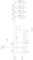
- Fig. 1 shows a schematic representation of a metering system 1 according to the invention (or the inventive method), with four laundry cleaning devices 2a to 2d via a respective washing medium supply line 23a to 23d (see Fig. 5 ) connected is.
- a single washing medium supply line for supplying a plurality of laundry cleaning devices 2a to 2d could also be provided, wherein the laundry cleaning devices 2a to 2d should then be equipped with additional connecting valves, so that a targeted supply is possible.
- the metering system 1 has two pumps 3a and 3b, which are preferably arranged within the metering system 1.
- the dosing system 1 is connected to two external pumps 4a and 4b, which may be provided to increase the pump power or as redundant pumps.
- the metering 1 is connected to a computer 5, by means of which the dosing 1 cleaning orders can be transmitted.
- the dosing system 1 further has a user interface 6, which may have, for example, a display, preferably an LCD display. Also, the display can be designed as a touch screen, whereby input by a user can be done very easily.
- the dosing system 1 is provided with at least one cleaning medium, according to Fig. 1 with eight cleaning media 24a to 24h (see Fig.
- each one cleaning medium 24a to 24h associated cleaning media ports 7a to 7h and optionally, for example, with a further eight cleaning media 24k to 24p are connected via a further eight cleaning media ports 7i to 7p, wherein the cleaning media 24a to 24p of the dosing system 1 via one in each case Fig. 1 not shown cleaning medium supply line 8a to 8h or 8p (see Fig. 5 ) connected to the cleaning media ports 7a to 7h and 7p, respectively, to hose ports 7a 'to 7h' and 7p ', respectively.
- the cleaning media connections 7a to 7h or 7p in this case have valves (cleaning medium valves), which are preferably designed as solenoid valves.
- a flushing medium unit 9 may be connected via a flushing medium supply line 10 with the metering system 1, wherein water is preferably used as flushing medium.
- the flushing medium unit 9 may comprise, for example, a closable connection, for example a faucet with a water connection.
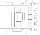
- Fig. 2 shows a front view of the dosing system 1 according to the invention, wherein the dosing 1 a power supply 11 for powering the dosing system 1, a computing unit 12, two drive units 13a and 13b, preferably each having an electric motor (which may be connected, for example, with a transmission), As well as various connections, which are described in more detail below.
- the drive units 13a and 13b are configured to drive the pumps 3a and 3b, respectively.
- the pumps 3a and 3b are preferably designed as peristaltic or peristaltic pumps.
- the arithmetic unit 12 is configured to store cleaning jobs as well as to control or regulate components involved in a dosing or cleaning process.
- the arithmetic unit 12 the drive units 13a and 13b as well as the valves associated with the cleaning media connections 7a to 7h are located substantially inside a housing 14 Fig. 2
- Dosing system 1 shown has two input terminals (a first input terminal 15a (see Fig. 3 ) and a second input terminal 15b, which in Fig.
- a first pump input port 18a associated with an input of the first pump 3a is shown, which is connected to the input distribution channel 16.
- second pump output port 19b is assigned second pump output port 19b, which is connected to the Wegverteilkanal 17.
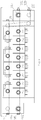
- Fig. 3 shows a sectional view of the metering system 1 according to the section line AA Fig. 2 , Therein, an input distribution channel 16 can be seen, which preferably extends horizontally through a lower portion of the dosing system 1.
- the input distribution channel 16 is connected to the first and a second pump input connection 18a and 18b.
- the cleaning media connections 7a to 7h (or in addition the cleaning media connection 7i to 7p) are arranged along the input distribution channel 16 so that through an opening of a respective cleaning media connection (preferably via a valve) a continuous connection of the matterssverteilkanals 16 with each of the cleaning media connection associated cleaning medium supply line 8a until 8h or 8p comes about.
- the input distribution channel 16 is connected via the two pump input ports 18a and 18b via the first and the second pump 3a and 3b with the Wegverteilkanal 17.
- a connecting line 20, which is preferably designed as a hose line the pump input port 18a connects to the pump 3a, wherein an output of the pump 3a is in turn connected via a further connecting line 20 with a first pump outlet port 19a.
- the connection of the matterssverteilkanals 16 with the Ninverteilkanals 17 via the second pump 3b is basically in an analogous manner.
- an additional connection line 21, which is preferably designed as a hose line is provided in order to connect the second pump output connection 19b to the output distribution channel 17.
- the output distribution channel 17 preferably extends parallel to the input channel 16 and is connected in the embodiment shown with four output terminals 22a to 22d, wherein the output terminals 22a to 22d preferably each have a valve, more preferably a solenoid valve, and by opening each one of the valves a continuous Connection of the Ninverteilkanals 17 of the respective output terminal 22a to 22d associated Waschmediumszutechnisch 23a to 23d is made.
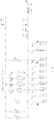
- Fig. 4 shows a side view of the dosing system 1 according to the Fig. 2 , wherein the dosing 1 in it with in Fig. 2 not shown connecting lines 20 is equipped.
- the first pump 3a is therein via the connection lines 20 to the first pump input port 18a and the first pump output port 19a, and configured to pump a purifying medium 24a to 24p from the input distribution passage 16 into the output distribution passage 17 and into subsequent washing medium supply passages 23a to 23d, respectively.
- that connecting line 20, which connects the pump 3a to the pump outlet port 19a executed in a length which preferably exceeds a minimum length necessary for the connection.
- This minimum length is preferably exceeded by 10%, 20%, 30% or 40%, so that, starting from the first pump 3a, this connecting line 20 extends at least in sections in an arc toward the pump outlet connection 19a.
- this connecting line 20 is squeezed and moved as a peristaltic pump in an embodiment of the first and second pump 3a and 3b, respectively.
- a generous dimensioning of this connection line 20 therefore prevents the risk of slippage from the pump outlet connection 19a.
- the increased freedom of bending reduces the amount of curvature of the connecting line 20, whereby its life can be further increased (this applies analogously to the connecting elements 20 of the second pump 3b).
- Fig. 5 is a schematic representation of a Spülmediums- and cleaning medium flow shown according to the invention.
- the flushing medium supply line 10 typically a line to a water connection
- a closable or openable connection 27 preferably a conventional main water tap and a system or pipe separator 28 (to avoid reflux in the flushing medium supply line 10) the first input terminal 15a and the second input terminal 15b is connected.
- a pressure sensor 29 is provided, which measures the pressure in the input distribution channel 16 and supplies the measured values to the arithmetic unit 12.
- a flow meter 25 which can be designed as a measuring wheel, in particular as a paddle wheel, is provided, which can be used to measure the input distribution channel 16 supplied amount of flushing medium.
- the dosing unit 1 opens according to the cleaning order that output (or output terminal 22a, 22b, 22c or 22d) or that output valve, which must be opened for connection to the desired laundry cleaning device 2a to 2d.
- an input or input valve is opened, which is typically first about the second input port 15b (assuming an open connection 27), so that flushing medium directly via the Ninverteilkanal 17, the respective output port 22a, 22b, 22c or 22d on the respective Waschmediumszutechnisch 23a to 23d in the respective washing medium supply line 23a to 23d associated laundry cleaning device 2a to 2d can pass.
- the second input connection 15b is closed and the first input connection 15a is opened, whereby the input distribution channel 16 is supplied with flushing medium.
- at least one of the pumps 3a, 3b, 4a or 4b is put into operation and a cleaning medium connection 7a (to 7p) is opened so that one of the cleaning media 24a to 24p mixes in the input distribution channel 16 with the flushing medium and via at least one of the pumps 3a, 3b, 4a or 4b is pumped into the Ninverteilkanal 17 and passes from there in the manner described above in a laundry cleaning device 2a to 2d.
- the flushing medium is mixed with the supplied cleaning medium 24a to 24j, whereby the chemical load on the lines participating in the supply to the respective laundry cleaning device 2a to 2d is reduced.
- the first input port 15a could also remain closed and the cleaning medium 24a to 24j be pumped in pure form into the respective laundry cleaning device 2a to 2d.
- the flushing medium is purged by closing the cleaning medium connection associated with the previously supplied cleaning medium 24a to 24j and supplying flushing medium via the input distribution channel 16 and the previously involved pumps to the laundry cleaning device 2a to 2d , Subsequently, another (or the same) cleaning medium connection can be opened and the supply to the laundry cleaning device 2a to 2d be continued in an analogous manner.
- the flushing of the matterssverteilkanals 17 and the downstream Ninverteilkanals 17 and the Waschmediumszutechnisch 23a to 23d allows the cleaning media 24a to 24j only in the laundry cleaning device 2a to 2d react with each other, thus preventing unwanted occurring in the leads reactions.
- the inlet channel 16, the outlet channel 17 and the washing medium supply line are rinsed in the manner already described with the rinsing medium.
- the required flushing amount is that amount which must necessarily be supplied to a laundry cleaning device 2a to 2d, around the metering system 1 and the respective washing medium supply line 23a to 23d largely free of cleaning media residues
- the first input port 15a again closed and the second input port 15b are opened, which now no pump has to be involved in the flushing medium supply and thus reduced energy consumption and the life of the pump can be increased.
- the dosing system and the lines to the laundry cleaning facilities 2a to 2d are largely free of cleaning media residues after flushing.
- the invention may be modified in any manner known to those skilled in the art and is not limited to the embodiment shown. Also, individual aspects of the invention can be taken up and largely combined with each other. Essential are the ideas underlying the invention, which in view of this doctrine can be performed by a person skilled in many ways and still remain maintained as such.
Abstract
Verfahren zum wechselweisen Zuführen eines Spülmediums und zumindest eines Reinigungsmediums (24a bis 24j) mittels einer Dosieranlage (1) für zumindest eine Wäschereinigungseinrichtung (2a,...2d), sowie Reinigungsvorrichtung zur Durchführung des Verfahrens, wobei der Dosieranlage (1) das Spülmedium über eine mit zumindest einem Eingangsanschluss (15a, 15b) verbundene Spülmediumszuleitung (10) zugeführt wird, und die Dosieranlage (1) mit jeder Wäschereinigungseinrichtung (2a,...2d) über jeweils eine Waschmediumszuleitung (23a bis 23d) mit einem Ausgangsanschluss (22a bis 22d) verbunden wird, umfassend die folgenden Schritte:
a) Erfassen eines automatisierten oder durch einen Benutzer vorgebbaren Reinigungsauftrages,
b) Überprüfen des Druckes in der Spülmediumszuleitung (10),
c) Zufuhr des Spülmediums an eine Wäschereinigungseinrichtung (2a,...2d) über die der Wäschereinigungseinrichtung (2a,...2d) zugeordnete Waschmediumszuleitung (23a bis 23d),
d) Zufuhr des zumindest einen Reinigungsmediums (24a bis 24j) an die Wäschereinigungseinrichtung (2a,...2d) gemäß Schritt c),
e) Spülen der Dosieranlage (1) und der Waschmediumszuleitung (23a bis 23d) mit dem Spülmedium für eine vorgebbare Zeitdauer.

a) detecting an automated cleaning job or a user-definable cleaning job,
b) checking the pressure in the flushing medium supply line (10),
c) supplying the flushing medium to a laundry cleaning device (2a,... 2d) via the washing medium feed line (23a to 23d) assigned to the laundry cleaning device (2a,... 2d),
d) feeding the at least one cleaning medium (24a to 24j) to the laundry cleaning device (2a, ... 2d) according to step c),
e) rinsing the dosing system (1) and the washing medium supply line (23a to 23d) with the rinsing medium for a predefinable period of time.
Description
Die Erfindung betrifft ein Verfahren zum wechselweisen Zuführen eines Spülmediums und zumindest eines Reinigungsmediums mittels einer Dosieranlage für zumindest eine Wäschereinigungseinrichtung, wobei der Dosieranlage das Spülmedium über eine mit zumindest einem Eingangsanschluss verbundene Spülmediumszuleitung zugeführt wird, und die Dosieranlage mit jeder Wäschereinigungseinrichtung über jeweils eine Waschmediumszuleitung mit einem Ausgangsanschluss verbunden wird.The invention relates to a method for alternately supplying a flushing medium and at least one cleaning medium by means of a metering for at least one laundry cleaning device, wherein the metering is supplied to the flushing medium via a connected to at least one inlet connection Spülmediumszuleitung, and the metering with each laundry cleaning device via a respective Waschmediumszuleitung with a Output terminal is connected.
Des Weiteren bezieht sich die Erfindung auf eine Reinigungsvorrichtung zur Durchführung des erfindungsgemäßen Verfahrens.Furthermore, the invention relates to a cleaning device for carrying out the method according to the invention.
Aus dem Stand der Technik sind Dosieranlagen für Wäschereinigungseinrichtungen bekannt geworden, wobei jeder Wäschereinigungseinrichtung jeweils eine Dosieranlage zugeordnet ist. Verfügt ein Benutzer über mehrere Wäschereinigungseinrichtungen, so hat dies zur Folge, dass auch mehrere Dosieranlagen vorgesehen werden müssen. Die Dosieranlagen erfüllen dabei den Zweck, ein Spülmedium sowie zumeist mehrere unterschiedliche Reinigungsmedien der jeweiligen Wäschereinigungseinrichtung in einer definierten Reihenfolge zuzuführen. Hierfür weisen die Dosieranlagen zumindest zwei Zuleitungen auf, die mit einer Wäschereinigungseinrichtung verbunden sind, nämlich eine Spülmediumszuleitung und zumindest eine Reinigungsmediumszuleitung. Das Reinigungsmedium wird dabei üblicherweise mittels einer Pumpe zur Wäschereinigungseinrichtung gepumpt. Häufig werden hierfür Schlauchquetschpumpen (sog. Peristaltikpumpen) eingesetzt, die die als Schlauch ausgeführte Reinigungsmediumszuleitung mechanisch beanspruchen und daher für einen zuverlässigen Betrieb möglichst elastische Schläuche voraussetzen. Reinigungsmittel, die die gewünschte Reinigungswirkung erzielen, haben häufig den unangenehmen Nebeneffekt, dass sie die Zusammensetzung der Schläuche verändern und somit deren Lebensdauer reduzieren. Dies führt zu verkürzten Wartungsintervallen sowie zu steigenden Betriebskosten oder schlimmstenfalls zu einer Leckage der Zuleitungen und in Folge dessen zu einem Totalausfall der Wäschereinigungseinrichtung. Da üblicherweise eine Mehrzahl an Reinigungsmedien bei einem Waschvorgang eingesetzt wird, und die Reinigungsmedien getrennt voneinander zugeführt werden müssen, um unerwünschte Reaktionen zwischen den Reinigungsmedien zu vermeiden, müssen in der Praxis mehrere Reinigungsmediumszuleitungen mit jeweils einer Pumpe vorgesehen werden. Die Vielzahl dieser Zuleitungen stellt nicht nur einen beträchtlichen Installations- und Kostenaufwand dar, sondern erhöht auch das Ausfallsrisiko der Wäschereinigungseinrichtung bzw. der Dosieranlage.Dosing systems for laundry cleaning devices have become known from the prior art, wherein each laundry cleaning device is assigned in each case a metering. If a user has several laundry cleaning devices, this has the consequence that several dosing systems must be provided. The dosing meet the purpose of supplying a flushing medium and usually several different cleaning media of the respective laundry cleaning device in a defined order. For this purpose, the metering at least two supply lines, which are connected to a laundry cleaning device, namely a Spülmediumszuleitung and at least one cleaning medium supply line. The cleaning medium is usually pumped by a pump to the laundry cleaning device. Peristaltic pumps (so-called peristaltic pumps) are frequently used for this purpose, which mechanically stress the cleaning medium feed line designed as a hose and therefore require the most flexible hoses possible for reliable operation. Detergents that achieve the desired cleaning effect often have the unpleasant side effect of changing the composition of the tubing and thus reducing their service life. This leads to shortened maintenance intervals and to rising operating costs or at worst to a leakage of the supply lines and as a result to a total failure of the laundry cleaning device. Since a plurality of cleaning media is usually used in a washing process, and the cleaning media must be supplied separately from each other in order to avoid undesirable reactions between the cleaning media, in practice, several cleaning medium supply lines be provided with one pump. The variety of these leads not only represents a considerable installation and cost, but also increases the risk of failure of the laundry cleaning device or dosing.
Es ist daher eine Aufgabe der Erfindung ein Verfahren bzw. eine Vorrichtung zum Zuführen eines Spülmediums und zumindest eines Reinigungsmediums mittels einer Dosieranlage zu schaffen, welche eine zuverlässige und kostengünstige Zufuhr des Spülmediums und zumindest eines Reinigungsmediums ermöglicht, und dabei gleichermaßen effizient und mit möglichst geringem Installationsaufwand ausführbar ist.It is therefore an object of the invention to provide a method and a device for supplying a flushing medium and at least one cleaning medium by means of a metering, which allows a reliable and cost-effective supply of the flushing medium and at least one cleaning medium, and equally efficient and with minimal installation costs is executable.
In einem ersten Aspekt der Erfindung wird diese Aufgabe mit einem Verfahren der eingangs genannten Art gelöst, bei welchem erfindungsgemäß folgende Schritte vorgesehen sind:
- a) Erfassen eines automatisierten oder durch einen Benutzer vorgebbaren Reinigungsauftrages,
- b) Überprüfen des Druckes in der Spülmediumszuleitung,
- c) Zufuhr des Spülmediums an eine Wäschereinigungseinrichtung über die der Wäschereinigungseinrichtung zugeordnete Waschmediumszuleitung,
- d) Zufuhr des zumindest einen Reinigungsmediums an die Wäschereinigungseinrichtung gemäß Schritt c),
- e) Spülen der Dosieranlage und der Waschmediumszuleitung mit dem Spülmedium für eine vorgebbare Zeitdauer.
- a) detecting an automated cleaning job or a user-definable cleaning job,
- b) checking the pressure in the flushing medium supply line,
- c) supplying the flushing medium to a laundry cleaning device via the washing medium supply line assigned to the laundry cleaning device,
- d) feeding the at least one cleaning medium to the laundry cleaning device according to step c),
- e) rinsing the dosing system and the washing medium supply line with the rinsing medium for a predefinable period of time.
Dank des erfindungsgemäßen Verfahrens ist es möglich eine Wäschereinigungseinrichtung mittels einer einzigen Waschmediumszuleitung zu versorgen, die sowohl die Zuleitung der des Spülmediums als auch des zumindest einen Reinigungsmediums von der Dosieranlage hin zu der Wäschereinigungseinrichtung übernimmt. Dadurch kann die Anzahl der Leitungen, die die Dosieranlage mit der Wäschereinigungseinrichtung verbinden, deutlich reduziert werden. Darüber hinaus ist die Lebensdauer der Waschmediumszuleitung deutlich höher als jene einer gleichwertigen Reinigungsmediumszuleitung, da Reinigungsmedien nur während der Zeitdauer, in der dem Wäschereinigungseinrichtung ein Reinigungsmedium zugeführt wird, in der Dosieranlage und der Waschmediumszuleitung verweilen. Die nachfolgende Spülung mit dem Spülmedium, welches vorzugsweise Wasser ist, erhöht die Lebensdauer der Dosieranlage und der Waschmediumszuleitung beträchtlich. Darüber hinaus wird das Reinigungsmedium vorzugsweise in Schritt d) mit dem Spülmedium vermengt, wodurch das Reinigungsmedium nur in verdünnter Form in die Waschmediumszuleitung gelangt. Die Lebensdauer der Waschmediumszuleitung kann dadurch zusätzlich erhöht werden. Der Ausdruck "wechselweises Zuführen von Spül- und Reinigungsmedien" bedeutet daher, dass ein Reinigungsmedium durchaus gleichzeitig mit einem Spülmedium zugeführt werden kann (dies ist sogar erwünscht); ein gleichzeitiges Zuführen mehrere unterschiedlicher Reinigungsmedien in einer Waschmediumszuleitung ist hingegen nicht vorgesehen.Thanks to the method according to the invention, it is possible to supply a laundry cleaning device by means of a single washing medium supply line, which takes over both the supply of the flushing medium and the at least one cleaning medium from the metering to the laundry cleaning device. As a result, the number of lines that connect the dosing with the laundry cleaning device can be significantly reduced. In addition, the service life of the washing medium supply line is significantly higher than that of an equivalent cleaning medium supply line, since cleaning media dwell only in the dosing system and the washing medium supply line during the period in which the laundry cleaning device is supplied with a cleaning medium. The subsequent rinsing with the rinsing medium, which is preferably water, increases the life of the dosing and the Waschmediumszuleitung considerably. In addition, the cleaning medium is preferably in step d) with the rinsing medium mixed, whereby the cleaning medium passes only in dilute form in the washing medium supply line. The life of the washing medium supply line can be additionally increased. The expression "alternately supplying rinsing and cleaning media" therefore means that a cleaning medium can be fed at the same time as a rinsing medium (this is even desirable); a simultaneous supply of several different cleaning media in a Waschmediumszuleitung, however, is not provided.
Das Erfassen des Reinigungsauftrages kann über eine Benutzerschnittstelle wie beispielsweise ein User-Terminal erfolgen, dass an der Dosieranlage angeordnet sein kann. Alternativ dazu kann ein Reinigungsauftrag auch von externen Geräten hin zur Dosieranlage übertragen werden. Auch ist es möglich, dass die Dosieranlage Aufträge in einer von dem Benutzer vorgebbaren Weise selbst automatisch generiert. Ein Reinigungsauftrag enthält vorzugsweise die Reinigungsparameter, in der die Menge und die Abfolge der der Wäschereinigungseinrichtung zuzuführenden Medien festgelegt ist. Auch kann die Einwirkdauer, die Reinigungstemperatur oder die Drehzahl einer Waschtrommel vorgegeben werden.The detection of the cleaning job can be done via a user interface such as a user terminal that can be located on the dosing. Alternatively, a cleaning order can also be transferred from external devices to the dosing system. It is also possible for the dosing system to automatically generate jobs in a manner that can be predetermined by the user. A cleaning job preferably contains the cleaning parameters in which the quantity and the sequence of the media to be supplied to the laundry cleaning device are fixed. Also, the exposure time, the cleaning temperature or the speed of a washing drum can be specified.
Das Spülen der Dosieranlage in Schritt e) erhöht zusätzlich die Lebensdauer der Dosieranlage bzw. darin vorgesehener Bauteile, indem beispielsweise ein Verkleben mechanisch bewegter oder beanspruchter Teile vorgebeugt wird. Nach erfolgter Spülung gemäß Schritt e) wird der Spülvorgang üblicherweise beendet, indem zumindest ein beteiligter Anschluss (Eingangsanschluss und/oder Ausgangsanschluss) geschlossen wird.Rinsing the dosing system in step e) additionally increases the service life of the dosing system or components provided therein, for example, by preventing sticking of mechanically moved or stressed parts. After rinsing according to step e), the rinsing process is usually ended by closing at least one participating connection (input connection and / or output connection).
In einer vorteilhaften Weiterbildung des erfindungsgemäßen Verfahrens kann es vorgesehen sein, dass jeder Eingangsanschluss ein Eingangsventil und jeder Ausgangsanschluss ein Ausgangsventil aufweist, wobei ergebnisabhängig von der Prüfung in Schritt b) zumindest ein Eingangsventil und das der Wäschereinigungseinrichtung gemäß Schritt c) zugeordnete Ausgangsventil vor dem Durchführen des Schritts c) geöffnet werden, wobei nach oder während des Schrittes c) ein dem jeweiligen Reinigungsmedium zugeordnetes ein Reinigungsmediumsventil für eine vorgebbare Zeitdauer geöffnet wird, und vor Schritt e) das geöffnete Reinigungsmediumsventil wieder geschlossen wird, wobei das Spülen gemäß Schritt e) in einem nach Schritt e) erfolgenden Schritt f) durch Schließen des jeweiligen Ausgangsventils und/oder der Eingangsventile beendet wird. Die Ausführung der besagten Anschlüsse als Ventile ist besonders effizient und erlaubt eine zuverlässige Zufuhr bzw. Zufuhrunterbrechung des Spülmediums bzw. des zumindest einen Reinigungsmediums an die jeweilige Wäschereinigungseinrichtung. Die Spülung der Dosieranlage gemäß Schritt e) des erfindungsgemäßen Verfahrens hat zur Folge, dass in der Dosieranlage vorhanden Ventile in einfacher Weise gereinigt werden, wodurch sich deren Haltbarkeit und Funktionsdauer erhöht.In an advantageous development of the method according to the invention, it may be provided that each input port has an input valve and each output port has an output valve, wherein at least one input valve and the output valve associated with the laundry cleaning device according to step c), depending on the result, from the test in step b) Step c) are opened, wherein after or during step c) a respective cleaning medium associated with a cleaning medium valve is opened for a predetermined period of time, and before step e) the opened cleaning medium valve is closed again, wherein the rinsing step e) in a after Step e) takes place step f) by closing the respective output valve and / or the input valves is terminated. The execution of said connections as valves is particularly efficient and allows a reliable supply or Supply interruption of the flushing medium or the at least one cleaning medium to the respective laundry cleaning device. The flushing of the dosing system according to step e) of the method according to the invention has the result that valves present in the dosing system are cleaned in a simple manner, which increases their durability and functional life.
Gemäß einer weiteren vorteilhaften Ausführungsform des erfindungsgemäßen Verfahrens kann vorgesehen sein, dass unterschiedliche Reinigungsmedien getrennt voneinander zuführbar sind, indem in einer dem Schritt e) nachfolgenden Iteration erneut die Schritte d) bis e) wiederholt werden. In jeder Iteration kann ein anderes Reinigungsmedium im jeweiligen Schritt d) in einer einzigen Waschmediumszuleitung einer Wäschereinigungseinrichtung zugeführt werden, ohne dass die Reinigungsmedien miteinander innerhalb der Dosieranlage oder der Waschmediumszuleitung miteinander in Berührung kommen. Dies erlaubt eine besonders zielgerichtete und effiziente Reinigung im Zuge eines umfassenden Reinigungsprogramms. Die Menge der zuzuführenden Reinigungsmittel kann beispielsweise durch eine entsprechend gewählte Pumpleistung einer die Reinigungsmittel und optional das Spülmittel zuführenden Pumpe vorgegeben werden.According to a further advantageous embodiment of the method according to the invention, it can be provided that different cleaning media can be supplied separately from one another by repeating steps d) to e) in an iteration following step e). In each iteration, another cleaning medium in the respective step d) can be supplied to a laundry cleaning device in a single washing medium supply line without the cleaning media coming into contact with one another within the metering system or the washing medium supply line. This allows a particularly targeted and efficient cleaning in the course of a comprehensive cleaning program. The amount of cleaning agent to be supplied can be predetermined, for example, by a correspondingly selected pumping capacity of a pump supplying the cleaning agent and optionally the flushing agent.
Um eine fehlerhafte Inbetriebnahme der Dosieranlage und einer Wäschereinigungseinrichtung vorzubeugen, kann gemäß einer günstigen Ausgestaltung des erfindungsgemäßen Verfahrens in Schritt a) das Fortbestehen des Reinigungsauftrages für eine Dauer von zumindest 5 Sekunden überprüft werden. Dies beugt eine Missinterpretation von fehlerhaften Signalen vor, die fälschlicherweise als Reinigungsauftrag interpretiert werden könnten. Solche fehlerhaften Signale können durch Einstreuungen oder Rückkopplungen verursacht werden, wie sie beispielsweise im Zuge einer Prüfung auf elektromagnetische Verträglichkeit gezielt in ein zu prüfendes System eingebracht werden.In order to prevent erroneous startup of the dosing and a laundry cleaning device, according to a favorable embodiment of the method according to the invention in step a) the persistence of the cleaning order for a period of at least 5 seconds can be checked. This prevents a misinterpretation of erroneous signals that could be misinterpreted as a cleaning job. Such faulty signals can be caused by interference or feedback, as they are specifically introduced, for example in the course of a test for electromagnetic compatibility in a system to be tested.
In einer weiteren günstigen Variante der Erfindung wird in Schritt e) die Durchflussrate des Spülmediums erfasst. So kann in einfacher Weise die Menge an Spülmedium bestimmt werden, die einer Wäschereinigungseinrichtung im Zuge eines Waschvorganges zugeführt wurde. Gegebenenfalls kann auf die Pumpleistung einer beteiligten Pumpe rückgeschlossen werden, wodurch eine notwendige baldige Wartung frühzeitig erkannt werden kann. Darüber hinaus kann der Vergleich der Pumpleistung mit der Durchflussrate dazu herangezogen werden, die Pumpe neu zu kalibrieren bzw. die Zeitdauer, in der das Spülmediumsowie die Reinigungsmedien zugeführt werden sollen, an eine geänderte Pumpleistung entsprechend anzupassen. Dies stellt sicher, dass auch bei geänderter Pumpleistung die gewünschte Menge an Spülmedium bzw. an Reinigungsmedien einer Wäschereinigungseinrichtung zugeführt werden kann. Das Erfassen kann z.B. durch eine indirekte Messung oder auch eine direkte Messung, beispielsweise mittels eines Messrades/Schaufelrades, erfolgen.In a further favorable variant of the invention, the flow rate of the flushing medium is detected in step e). Thus, the amount of flushing medium can be determined in a simple manner, which was supplied to a laundry cleaning device in the course of a washing process. If necessary, it is possible to deduce the pumping power of a pump involved, as a result of which a necessary early maintenance can be detected early. In addition, the comparison of the pumping power with the flow rate can be used to recalibrate the pump or the period of time in which the flushing medium as well the cleaning media are to be supplied, adapted to a changed pumping power accordingly. This ensures that even with a changed pumping capacity, the desired amount of flushing medium or of cleaning media can be supplied to a laundry cleaning device. The detection can be done for example by an indirect measurement or a direct measurement, for example by means of a measuring wheel / paddle wheel.
In einer Weiterbildung des erfindungsgemäßen Verfahrens kann vorgesehen sein, dass die Durchflussrate in der Spülmediumszuleitung und in der Waschmediumszuleitung erfasst wird. Die Differenz der beiden Durchflussraten kann z.B. zur Bewertung der Dichtheit der Dosieranlage herangezogen werden.In a development of the method according to the invention, provision can be made for the flow rate in the flushing medium feed line and in the washing medium feed line to be detected. The difference of the two flow rates can e.g. be used to assess the tightness of the dosing.
Gemäß einer weiteren vorteilhaften Ausgestaltung der Erfindung kann vorgesehen sein, dass die Verfügbarkeit der Reinigungsmedien überprüft wird und ergebnisabhängig davon Warn- und/oder Leermeldungen ausgegeben werden und/oder die Wäschereinigungseinrichtung gestoppt wird. Die Überprüfung der Verfügbarkeit der Reinigungsmedien kann beispielsweise über einfache Sensoren erfolgen, die den Füllstand von Behältnissen messen, die besagte Reinigungsmedien beinhalten. Hierfür sind beispielsweise Schwimmsensoren oder andere Füllstandssensoren besonders geeignet.According to a further advantageous embodiment of the invention, it may be provided that the availability of the cleaning media is checked and, depending on the result thereof, warning and / or empty messages are output and / or the laundry cleaning device is stopped. The availability of the cleaning media can be checked, for example, by simple sensors which measure the fill level of containers containing said cleaning media. For this purpose, for example, swimming sensors or other level sensors are particularly suitable.
Um einen möglichst zuverlässigen und effizienten Betrieb der Dosieranlage zu gewährleisten, kann vorgesehen sein, dass in Schritt b) der Druck in der Spülmediumszuleitung gemessen und bei Unterschreiten eines definierten Wertes, beispielsweise 0,7 oder 0,5 bar, die Schritte c) bis e) ausgesetzt werden. Zusätzlich kann vorgesehen sein, dass bei Unterschreiten des definierten Wertes die Dosieranlage eine Fehlermeldung ausgibt.In order to ensure the most reliable and efficient operation of the metering, it can be provided that in step b) the pressure in the flushing medium supply line and falls below a defined value, for example 0.7 or 0.5 bar, the steps c) to e ) get abandoned. In addition, it can be provided that when the value falls below the defined value, the dosing system issues an error message.
Um die Robustheit und Zuverlässigkeit der Dosieranlage weiter zu erhöhen, kann vorgesehen sein, dass die Dosieranlage zur Einbringung des Spülmediums und des Reinigungsmediums zwei hydraulisch parallel geschaltete Pumpen, vorzugsweise Peristaltikpumpen aufweist. Im Falle eines Ausfalls einer Pumpe kann die Versorgung der Wäschereinigungseinrichtungen von der anderen Pumpe zuverlässig übernommen werden. Alternativ können natürlich auch drei oder mehr Pumpen vorgesehen sein. Auch könnte lediglich eine Pumpe vorgesehen sein, allerdings wäre dies mit einem deutlich erhöhten Ausfallsrisiko verbunden.In order to further increase the robustness and reliability of the dosing system, it can be provided that the dosing system for the introduction of the flushing medium and the cleaning medium has two hydraulically connected in parallel pumps, preferably peristaltic pumps. In the event of failure of a pump, the supply of laundry cleaning equipment can be reliably taken over by the other pump. Alternatively, of course, three or more pumps may be provided. Also, only one pump could be provided, but this would be associated with a significantly increased risk of failure.
In einer günstigen Ausgestaltung der Erfindung wird in Schritt f) die Förderleistung der Pumpen gemessen und mit vorgebbaren Sollwerten verglichen. Dies erlaubt ein einfaches Kalibrieren der Pumpen und ein Anpassen der Reinigungsparameter. Auch kann eine deutliche Abweichung von Sollwerten dazu herangezogen werden, um auf einen fehlerhaften Zustand einer Pumpe und einen eventuell notwendigen Austausch zurück zu schließen.In a favorable embodiment of the invention, the delivery rate of the pumps is measured in step f) and compared with predefinable setpoint values. This allows easy calibration of the pumps and adjustment of the cleaning parameters. Also, a significant deviation from setpoints can be used to infer a faulty state of a pump and any necessary replacement back.
In einem vorteilhaften Ausführung des erfindungsgemäßen Verfahren kann vorgesehen sein, dass die Dosieranlage den Zustand der mit der Dosiereinrichtung verbundenen Wäschereinigungseinrichtungen sowie die Verfügbarkeit des Spül- und Reinigungsmediums überwacht und bei Abweichungen von Sollwerten eine Fehlermeldung ausgibt, die vorzugsweise zusätzlich als elektronische Nachricht an eine Empfangstelle übermittelt wird. So kann beispielsweise eine Nachricht auf einem an der Dosieranlage angebrachtem Terminal bzw. Display angezeigt werden oder eine Warnleuchte auf eine Abweichung von Sollwerten hinweisen. Besonders bevorzugt kann auch eine automatische Nachricht, beispielsweise eine SMS an ein Mobiltelefon eines Benutzers, des Inhabers und/oder eines Wartungsteams gesendet werden.In an advantageous embodiment of the method according to the invention, it can be provided that the dosing system monitors the state of the laundry cleaning devices connected to the dosing device and the availability of the rinsing and cleaning medium and, in the event of deviations from nominal values, outputs an error message, which preferably additionally transmits this as an electronic message to a receiving point becomes. For example, a message can be displayed on a terminal or display attached to the dosing system, or a warning light can indicate a deviation from setpoint values. Particularly preferably, an automatic message, for example a text message to a mobile phone of a user, the owner and / or a maintenance team can be sent.
Um eine einfache digitale Anbindung der Dosieranlage zu ermöglichen, kann es vorgesehen sein, dass die Dosieranlage ein Modul zur Herstellung einer Funkverbindung, vorzugsweise einer W-Lan Verbindung aufweist, wobei die Dosieranlage vorzugsweise dazu eingerichtet ist, mittels einer externen Kommunikationsschnittstelle überwacht und/oder gesteuert zu werden. Als externe Kommunikationsschnittstelle können zum Beispiel Mobiltelefone, insbesondere Smartphones, Tabletcomputer oder auch beliebige andere Geräte mit einer digitalen Kommunikationsschnittstelle verwendet werden.In order to enable a simple digital connection of the dosing system, it can be provided that the dosing system has a module for producing a radio connection, preferably a W-Lan connection, the dosing system is preferably adapted to be monitored and / or controlled by means of an external communication interface to become. As an external communication interface, for example, mobile phones, especially smartphones, tablet computers or any other devices can be used with a digital communication interface.
Gemäß einer weiteren Ausgestaltung des erfindungsgemäßen Verfahrens können zumindest zwei, vorzugsweise vier, acht oder mehr Wäschereinigungseinrichtungen mit der Dosieranlage über jeweils eine Waschmediumszuleitung verbunden werden. Dabei ist jede Waschmediumszuleitung mit jeweils einem Ausgangsanschluss der Dosieranlage verbunden, wobei jeder Ausgangsanschluss vorzugsweise ein Ausgangsventil aufweist.According to a further embodiment of the method according to the invention, at least two, preferably four, eight or more laundry cleaning devices can be connected to the dosing system via a respective washing medium supply line. In this case, each washing medium supply line is connected in each case to an outlet connection of the metering system, wherein each outlet connection preferably has an outlet valve.
Um die Betriebssicherheit der Dosieranlage weiter zu erhöhen, kann in einer günstigen Variante des erfindungsgemäßen Verfahrens vorgesehen sein, dass der Druck in der Waschmediumszuleitung überwacht wird. Dies kann über herkömmliche Drucksensoren erfolgen.
In einem zweiten Aspekt der Erfindung wird die oben gestellte Aufgabe mit einer Reinigungsvorrichtung zur Durchführung des erfindungsgemäßen Verfahrens gemäß einem oder einer beliebigen Kombination der zuvor genannten Ausführungsformen gelöst.In order to further increase the operational reliability of the dosing system, it can be provided in a favorable variant of the method according to the invention that the pressure in the Washing medium supply line is monitored. This can be done via conventional pressure sensors.
In a second aspect of the invention, the above object is achieved with a cleaning device for carrying out the method according to the invention according to one or any combination of the aforementioned embodiments.
In einer günstigen Ausgestaltung der Erfindung weist die Reinigungsvorrichtung die Dosieranlage, die Spülmediumszuleitung, das Eingangsventil, die Waschmediumszuleitung und das Ausgangsventil auf.In a favorable embodiment of the invention, the cleaning device, the metering, the Spülmediumszuleitung, the input valve, the Waschmediumszuleitung and the output valve.
Gemäß einer vorteilhaften Ausführungsform kann es vorgesehen sein, dass die Dosieranlage zum wechselweisen Zuführen eines Spülmediums und zumindest eines Reinigungsmediums einen Eingangsverteilkanal sowie einen Ausgangsverteilkanal aufweist, wobei das zumindest eine Reinigungsmedium über jeweils eine mit dem Eingangsverteilkanal verbundene Reinigungsmediumszuleitung in den Eingangsverteilkanal einbringbar ist und der Eingangsverteilkanal zusätzlich mit der Spülmediumszuleitung verbunden ist, und der Ausgangsverteilkanal mit der Waschmediumszuleitung verbunden ist, wobei der Eingangsverteilkanal mit dem Ausgangsverteilkanal über zumindest eine Pumpe, vorzugsweise über zwei Pumpen, verbunden ist. Alternativ dazu können auch drei oder mehr Pumpen vorgesehen sein. Die Pumpen können beliebige Pumpen sein, die geeignet sind das Spülmedium sowie das Reinigungsmedium sowie das Waschmedium weiter zu befördern. Bevorzugt werden hierbei Schlauchquetschpumpen bzw. Peristaltikpumpen eingesetzt. Das Vorsehen der Kanäle erlaubt eine einfache und effiziente Anordnung von Eingangs- und Ausgangsleitungen, die in einfacher Weise vorzugsweise über Ventile zu und abgeschaltet werden können.According to an advantageous embodiment, it can be provided that the dosing system for alternately supplying a flushing medium and at least one cleaning medium has an input distribution channel and a Ausgangsverteilkanal, wherein the at least one cleaning medium via one connected to the Eingangsverteilkanal cleaning medium supply into the Eingangsverteilkanal is introduced and the Eingangsverteilkanal additional is connected to the Spülmediumszuleitung, and the Ausgangsverteilkanal is connected to the Waschmediumszuleitung, wherein the Eingangsverteilkanal is connected to the Ausgangsverteilkanal via at least one pump, preferably via two pumps. Alternatively, three or more pumps may be provided. The pumps can be any pumps which are suitable for conveying the flushing medium as well as the cleaning medium and the washing medium. Percussion pumps or peristaltic pumps are preferably used here. The provision of the channels allows a simple and efficient arrangement of input and output lines, which can be switched on and off in a simple manner preferably via valves.
In einer besonders günstigen Variante der Erfindung ist der Ausgangsverteilkanal mit der Spülmediumszuleitung verbunden. Dies erlaubt eine direkte Spülung des Ausgangsverteilkanals ohne die den Eingangsverteilkanal mit dem Ausgangsverteilkanal hydraulisch verbindenden Pumpen in Anspruch nehmen zu müssen. Dadurch können die Pumpen sowie die den Pumpen zugeordneten Leitungen, die vorzugsweise als Schläuche ausgeführt sind, geschont werden.In a particularly favorable variant of the invention, the output distribution channel is connected to the flushing medium supply line. This allows a direct flushing of the Ausgangsverteilkanals without having to take the input distribution channel with the Ausgangsverteilkanal hydraulically connecting pumps. As a result, the pumps and the lines associated with the pumps, which are preferably designed as hoses, can be spared.
Die Erfindung samt weiteren Ausgestaltungen und Vorteilen ist im Folgenden an Hand einer beispielhaften, nicht einschränkenden Ausführungsform näher erläutert, die in den Figuren veranschaulicht ist. Hierbei zeigt
-
Fig. 1 eine schematische Darstellung einer Dosieranlage mit mehreren Wäschereinigungseinrichtungen gemäß der Erfindung, -
Fig. 2 eine Vorderansicht der Dosieranlage gemäß der Erfindung, -
Fig. 3 eine Schnittdarstellung der Dosieranlage gemäß der Schnittlinie AA ausFig. 2 , -
Fig. 4 eine Seitenansicht der Dosieranlage gemäßFig. 2 und -
Fig. 5 eine schematische Darstellung eines Spülmediums- und Reinigungsmediumsflusses gemäß der Erfindung.
-
Fig. 1 a schematic representation of a dosing with several laundry cleaning devices according to the invention, -
Fig. 2 a front view of the dosing system according to the invention, -
Fig. 3 a sectional view of the dosing according to the section line AAFig. 2 . -
Fig. 4 a side view of the metering according toFig. 2 and -
Fig. 5 a schematic representation of a Spülmediums- and cleaning medium flow according to the invention.
Die Antriebseinheiten 13a und 13b sind dazu eingerichtet die Pumpen 3a bzw. 3b anzutreiben. Die Pumpen 3a und 3b sind vorzugsweise als Schlauchquetsch- bzw. Peristaltikpumpen ausgeführt. Die Recheneinheit 12 ist dazu eingerichtet Reinigungsaufträge zu speichern sowie an einem Dosier- bzw. Reinigungsvorgang beteiligte Komponenten zu steuern oder zu regeln. Um einen kompakten und robusten Aufbau der Dosieranlage 1 zu ermöglichen, befinden sich die Recheneinheit 12, die Antriebseinheiten 13a und 13b sowie die den Reinigungsmedienanschlüsse 7a bis 7h zugeordneten Ventile im Wesentlichen innerhalb eines Gehäuses 14. Die in
In
Wird der Dosieranlage 1 ein Reinigungsauftrag erteilt, so öffnet die Dosieranlage 1 entsprechend dem Reinigungsauftrag jenen Ausgang (bzw. Ausgangsanschluss 22a, 22b, 22c oder 22d) bzw. jenes Ausgangsventil, das zur Verbindung mit der gewünschten Wäschereinigungseinrichtung 2a bis 2d geöffnet werden müssen. Zudem wird ein Eingang bzw. Eingangsventil geöffnet, wobei es sich dabei typischerweise zuerst um den zweiten Eingangsanschluss 15b handelt (eine geöffnete Verbindung 27 vorausgesetzt), sodass Spülmedium direkt über den Ausgangsverteilkanal 17, den jeweiligen Ausgangsanschluss 22a, 22b, 22c oder 22d über die jeweilige Waschmediumszuleitung 23a bis 23d in die der jeweiligen Waschmediumszuleitung 23a bis 23d zugeordnete Wäschereinigungseinrichtung 2a bis 2d gelangen kann. Nach einer vorgebbaren Zeitdauer bzw. Spülmediumsmenge wird der zweite Eingangsanschluss 15b geschlossen und der erste Eingangsanschluss 15a geöffnet, wodurch der Eingangsverteilkanal 16 mit Spülmedium versorgt wird. Zusätzlich wird zumindest eine der Pumpen 3a, 3b, 4a oder 4b in Betrieb genommen und ein Reinigungsmediumsanschluss 7a (bis 7p) geöffnet, sodass eines der Reinigungsmedien 24a bis 24p sich in dem Eingangsverteilkanal 16 mit dem Spülmedium vermengt und über zumindest eine der Pumpen 3a, 3b, 4a oder 4b in den Ausgangsverteilkanal 17 gepumpt wird und von dort in obig beschriebener Weise in eine Wäschereinigungseinrichtung 2a bis 2d gelangt. Das Spülmedium vermengt sich dabei mit dem zugeführten Reinigungsmedium 24a bis 24j, wodurch die chemische Belastung der an der Zufuhr an die jeweilige Wäschereinigungseinrichtung 2a bis 2d beteiligten Leitungen reduziert wird. Alternativ dazu könnte der erste Eingangsanschluss 15a auch verschlossen bleiben und das Reinigungsmedium 24a bis 24j in Reinform in die jeweilige Wäschereinigungseinrichtung 2a bis 2d gepumpt werden. Nach erfolgter Zufuhr des Reinigungsmediums 24a bis 24j folgt eine Spülung des Eingangskanals mit dem Spülmedium, indem der dem zuvor zugeführten Reinigungsmedium 24a bis 24j zugeordnete Reinigungsmediumsanschluss geschlossen wird und Spülmedium über den Eingangsverteilkanal 16 und die zuvor beteiligte/n Pumpen der Wäschereinigungseinrichtung 2a bis 2d zugeführt werden. Im Anschluss kann ein anderer (oder auch der gleiche) Reinigungsmediumsanschluss geöffnet werden und die Zufuhr an die Wäschereinigungseinrichtung 2a bis 2d in analoger Weise fortgesetzt werden. Die Spülung des Eingangsverteilkanals 17 bzw. des nachgeschalteten Ausgangsverteilkanals 17 und der Waschmediumszuleitung 23a bis 23d ermöglicht, dass die Reinigungsmedien 24a bis 24j erst in der Wäschereinigungseinrichtung 2a bis 2d miteinander reagieren und verhindert so unerwünschte in den Zuleitungen erfolgende Reaktionen. Nachdem alle gewünschten Reinigungsmedien 24a bis 24j zugeführt wurden wird der Eingangskanal 16, der Ausgangskanal 17 und der Waschmediumszuleitung in bereits beschriebener Weise mit dem Spülmedium gespült. Sollte eine höhere Menge an Spülmedium an die Wäschereinigungseinrichtung 2a bis 2d zugeführt werden, als für die besagte Spülung erforderlich ist (die erforderliche Spülmenge ist jene Menge, die notwendigerweise einer Wäschereinigungseinrichtung 2a bis 2d zugeführt werden muss, um die Dosieranlage 1 und die jeweilige Waschmediumszuleitung 23a bis 23d weitgehend von Reinigungsmedienrückständen zu befreien), so kann das erste Eingangsanschluss 15a wieder geschlossen und der zweite Eingangsanschluss 15b geöffnet werden, wodurch nunmehr keine Pumpe an der Spülmediumszufuhr beteiligt werden muss und somit der Energieverbrauch gesenkt sowie die Lebensdauer der Pumpen gesteigert werden kann. Die Dosieranlage und die Leitungen hin zu den Wäschereinigungseinrichtungen 2a bis 2d sind nach erfolgter Spülung weitgehend frei von Reinigungsmedienrückständen.If the
Die Erfindung kann in beliebiger dem Fachmann bekannter Weise abgeändert werden und ist nicht auf die gezeigte Ausführungsform beschränkt. Auch können einzelne Aspekte der Erfindung aufgegriffen und weitgehend miteinander kombiniert werden. Wesentlich sind die der Erfindung zugrunde liegenden Gedanken, welche in Anbetracht dieser Lehre durch einen Fachmann in mannigfaltiger Weise ausgeführt werden können und trotzdem als solche aufrechterhalten bleiben.
Claims (15)
Priority Applications (1)
| Application Number | Priority Date | Filing Date | Title |
|---|---|---|---|
| SI201531324T SI3467183T1 (en) | 2014-01-29 | 2015-01-28 | Compact metering system |
Applications Claiming Priority (3)
| Application Number | Priority Date | Filing Date | Title |
|---|---|---|---|
| ATA50059/2014A AT515402A1 (en) | 2014-01-29 | 2014-01-29 | Compact dispensing |
| EP15709818.7A EP3099852B1 (en) | 2014-01-29 | 2015-01-28 | Compact metering system |
| PCT/AT2015/050025 WO2015113091A1 (en) | 2014-01-29 | 2015-01-28 | Compact metering system |
Related Parent Applications (1)
| Application Number | Title | Priority Date | Filing Date |
|---|---|---|---|
| EP15709818.7A Division EP3099852B1 (en) | 2014-01-29 | 2015-01-28 | Compact metering system |
Publications (2)
| Publication Number | Publication Date |
|---|---|
| EP3467183A1 true EP3467183A1 (en) | 2019-04-10 |
| EP3467183B1 EP3467183B1 (en) | 2020-06-10 |
Family
ID=52682578
Family Applications (2)
| Application Number | Title | Priority Date | Filing Date |
|---|---|---|---|
| EP18209724.6A Active EP3467183B1 (en) | 2014-01-29 | 2015-01-28 | Compact metering system |
| EP15709818.7A Not-in-force EP3099852B1 (en) | 2014-01-29 | 2015-01-28 | Compact metering system |
Family Applications After (1)
| Application Number | Title | Priority Date | Filing Date |
|---|---|---|---|
| EP15709818.7A Not-in-force EP3099852B1 (en) | 2014-01-29 | 2015-01-28 | Compact metering system |
Country Status (5)
| Country | Link |
|---|---|
| EP (2) | EP3467183B1 (en) |
| AT (2) | AT14982U1 (en) |
| ES (1) | ES2816016T3 (en) |
| SI (1) | SI3467183T1 (en) |
| WO (1) | WO2015113091A1 (en) |
Families Citing this family (1)
| Publication number | Priority date | Publication date | Assignee | Title |
|---|---|---|---|---|
| EP4286579A1 (en) * | 2022-06-01 | 2023-12-06 | The Procter & Gamble Company | Array of laundry washing machines |
Citations (4)
| Publication number | Priority date | Publication date | Assignee | Title |
|---|---|---|---|---|
| US5246026A (en) * | 1992-05-12 | 1993-09-21 | Proudman Systems, Inc. | Fluid measuring, dilution and delivery system |
| WO1996041910A1 (en) * | 1995-06-08 | 1996-12-27 | Unilever N.V. | Process and device for dosing detergent compositions |
| US6035472A (en) * | 1997-05-31 | 2000-03-14 | U.N.X. Inc | Method of dispensing chemicals |
| DE102007032759A1 (en) * | 2007-07-13 | 2009-01-15 | BSH Bosch und Siemens Hausgeräte GmbH | Method for cleaning dosing lines in automatically controlled laundry treatment machines |
Family Cites Families (2)
| Publication number | Priority date | Publication date | Assignee | Title |
|---|---|---|---|---|
| US4845965A (en) * | 1986-12-23 | 1989-07-11 | Ecolab Inc. | Method and apparatus for dispensing solutions |
| US5014211A (en) * | 1989-06-16 | 1991-05-07 | Diversey Corporation | Microprocessor controlled liquid chemical delivery system and method |
-
2014
- 2014-01-29 AT ATGM8037/2015U patent/AT14982U1/en not_active IP Right Cessation
- 2014-01-29 AT ATA50059/2014A patent/AT515402A1/en unknown
-
2015
- 2015-01-28 EP EP18209724.6A patent/EP3467183B1/en active Active
- 2015-01-28 WO PCT/AT2015/050025 patent/WO2015113091A1/en active Application Filing
- 2015-01-28 SI SI201531324T patent/SI3467183T1/en unknown
- 2015-01-28 EP EP15709818.7A patent/EP3099852B1/en not_active Not-in-force
- 2015-01-28 ES ES18209724T patent/ES2816016T3/en active Active
Patent Citations (4)
| Publication number | Priority date | Publication date | Assignee | Title |
|---|---|---|---|---|
| US5246026A (en) * | 1992-05-12 | 1993-09-21 | Proudman Systems, Inc. | Fluid measuring, dilution and delivery system |
| WO1996041910A1 (en) * | 1995-06-08 | 1996-12-27 | Unilever N.V. | Process and device for dosing detergent compositions |
| US6035472A (en) * | 1997-05-31 | 2000-03-14 | U.N.X. Inc | Method of dispensing chemicals |
| DE102007032759A1 (en) * | 2007-07-13 | 2009-01-15 | BSH Bosch und Siemens Hausgeräte GmbH | Method for cleaning dosing lines in automatically controlled laundry treatment machines |
Also Published As
| Publication number | Publication date |
|---|---|
| AT515402A1 (en) | 2015-08-15 |
| AT14982U1 (en) | 2016-10-15 |
| EP3099852B1 (en) | 2018-12-05 |
| EP3467183B1 (en) | 2020-06-10 |
| SI3467183T1 (en) | 2020-12-31 |
| WO2015113091A1 (en) | 2015-08-06 |
| ES2816016T3 (en) | 2021-03-31 |
| EP3099852A1 (en) | 2016-12-07 |
Similar Documents
| Publication | Publication Date | Title |
|---|---|---|
| DE102017114665A1 (en) | Dosing device u.a. | |
| EP2448685B1 (en) | Device and method for cleaning wastewater lines of vacuum toilet systems | |
| EP2096214A2 (en) | Drinking service water supply device of a building and control device for same | |
| DE102009048690A1 (en) | Substrate coating system and method of operation for this system | |
| DE112006000284T5 (en) | A hydraulic auxiliary system with an accumulator for a concrete pump to increase the flow rate | |
| EP3467183B1 (en) | Compact metering system | |
| EP0260649B1 (en) | Method for the internal cleaning of branched pipings and/or units, and device for carrying out this method | |
| DE102011011202A1 (en) | Protection device for protecting pump from overheating or before dry running, particularly for protecting procedural process units, has fluid lines, housing and mounting plate | |
| EP2844478B1 (en) | Device for setting an operating parameter of ink for a printing process of a rotary printing press and method therefor | |
| EP2679975A2 (en) | Device and method for detecting a fracture in a fluid line | |
| WO2023020722A1 (en) | System comprising an installation having a heating system and a device or component, and method for determining the energy consumption of the installation | |
| EP2799128B1 (en) | Device for metering at least one chemical into a medium | |
| EP3382366B1 (en) | Sampling system for taking fuel samples | |
| DE102012218754B4 (en) | Method for operating a cleaning machine | |
| DE4321008C1 (en) | Haemodialysis unit hydraulic circuit with cleaning or disinfectant circuit - applies preset pressure to buffer volume formed between non-return valve and magnetic stop valve, and couples pressure sensor between volume and microprocessor | |
| WO2015165733A2 (en) | Metering system for the dosed delivery of chemical substances stored in containers to a dishwashing machine or washing machine | |
| WO2006034852A1 (en) | Method and device for the diagnosis of technical devices disposed within an industrial installation | |
| EP2357270B1 (en) | Bleed and feed device and method | |
| WO2019154717A1 (en) | Freezing protection device and freezing protection method for a vehicle treatment system | |
| DE102022113915A1 (en) | Testing device for testing fluid-carrying components | |
| DE10159163B4 (en) | Device and method for dosing pasty products | |
| DE202018104809U1 (en) | Plant for the automatic disinfection of medical pipelines | |
| DE102016005346A1 (en) | Method for monitoring the cooling lubricant for a machine tool | |
| WO2016162185A1 (en) | Monitoring of the connection of fluid lines to surgical instruments | |
| DE10337800A1 (en) | Method for correctively controlling a vapor recovery system at a gas station |
Legal Events
| Date | Code | Title | Description |
|---|---|---|---|
| PUAI | Public reference made under article 153(3) epc to a published international application that has entered the european phase |
Free format text: ORIGINAL CODE: 0009012 |
|
| STAA | Information on the status of an ep patent application or granted ep patent |
Free format text: STATUS: THE APPLICATION HAS BEEN PUBLISHED |
|
| AC | Divisional application: reference to earlier application |
Ref document number: 3099852 Country of ref document: EP Kind code of ref document: P |
|
| AK | Designated contracting states |
Kind code of ref document: A1 Designated state(s): AL AT BE BG CH CY CZ DE DK EE ES FI FR GB GR HR HU IE IS IT LI LT LU LV MC MK MT NL NO PL PT RO RS SE SI SK SM TR |
|
| STAA | Information on the status of an ep patent application or granted ep patent |
Free format text: STATUS: REQUEST FOR EXAMINATION WAS MADE |
|
| 17P | Request for examination filed |
Effective date: 20190924 |
|
| RBV | Designated contracting states (corrected) |
Designated state(s): AL AT BE BG CH CY CZ DE DK EE ES FI FR GB GR HR HU IE IS IT LI LT LU LV MC MK MT NL NO PL PT RO RS SE SI SK SM TR |
|
| RIC1 | Information provided on ipc code assigned before grant |
Ipc: D06F 39/02 20060101AFI20191114BHEP Ipc: D06F 33/02 20060101ALN20191114BHEP |
|
| RIC1 | Information provided on ipc code assigned before grant |
Ipc: D06F 33/02 20060101ALN20191115BHEP Ipc: D06F 39/02 20060101AFI20191115BHEP |
|
| RIC1 | Information provided on ipc code assigned before grant |
Ipc: D06F 39/02 20060101AFI20191126BHEP Ipc: D06F 33/02 20060101ALN20191126BHEP |
|
| GRAP | Despatch of communication of intention to grant a patent |
Free format text: ORIGINAL CODE: EPIDOSNIGR1 |
|
| STAA | Information on the status of an ep patent application or granted ep patent |
Free format text: STATUS: GRANT OF PATENT IS INTENDED |
|
| INTG | Intention to grant announced |
Effective date: 20200103 |
|
| GRAS | Grant fee paid |
Free format text: ORIGINAL CODE: EPIDOSNIGR3 |
|
| GRAA | (expected) grant |
Free format text: ORIGINAL CODE: 0009210 |
|
| STAA | Information on the status of an ep patent application or granted ep patent |
Free format text: STATUS: THE PATENT HAS BEEN GRANTED |
|
| AC | Divisional application: reference to earlier application |
Ref document number: 3099852 Country of ref document: EP Kind code of ref document: P |
|
| AK | Designated contracting states |
Kind code of ref document: B1 Designated state(s): AL AT BE BG CH CY CZ DE DK EE ES FI FR GB GR HR HU IE IS IT LI LT LU LV MC MK MT NL NO PL PT RO RS SE SI SK SM TR |
|
| REG | Reference to a national code |
Ref country code: GB Ref legal event code: FG4D Free format text: NOT ENGLISH |
|
| REG | Reference to a national code |
Ref country code: CH Ref legal event code: EP Ref country code: AT Ref legal event code: REF Ref document number: 1279277 Country of ref document: AT Kind code of ref document: T Effective date: 20200615 |
|
| REG | Reference to a national code |
Ref country code: DE Ref legal event code: R096 Ref document number: 502015012780 Country of ref document: DE |
|
| REG | Reference to a national code |
Ref country code: IE Ref legal event code: FG4D Free format text: LANGUAGE OF EP DOCUMENT: GERMAN |
|
| REG | Reference to a national code |
Ref country code: NL Ref legal event code: FP |
|
| REG | Reference to a national code |
Ref country code: LT Ref legal event code: MG4D |
|
| PG25 | Lapsed in a contracting state [announced via postgrant information from national office to epo] |
Ref country code: LT Free format text: LAPSE BECAUSE OF FAILURE TO SUBMIT A TRANSLATION OF THE DESCRIPTION OR TO PAY THE FEE WITHIN THE PRESCRIBED TIME-LIMIT Effective date: 20200610 Ref country code: GR Free format text: LAPSE BECAUSE OF FAILURE TO SUBMIT A TRANSLATION OF THE DESCRIPTION OR TO PAY THE FEE WITHIN THE PRESCRIBED TIME-LIMIT Effective date: 20200911 Ref country code: FI Free format text: LAPSE BECAUSE OF FAILURE TO SUBMIT A TRANSLATION OF THE DESCRIPTION OR TO PAY THE FEE WITHIN THE PRESCRIBED TIME-LIMIT Effective date: 20200610 Ref country code: NO Free format text: LAPSE BECAUSE OF FAILURE TO SUBMIT A TRANSLATION OF THE DESCRIPTION OR TO PAY THE FEE WITHIN THE PRESCRIBED TIME-LIMIT Effective date: 20200910 Ref country code: SE Free format text: LAPSE BECAUSE OF FAILURE TO SUBMIT A TRANSLATION OF THE DESCRIPTION OR TO PAY THE FEE WITHIN THE PRESCRIBED TIME-LIMIT Effective date: 20200610 |
|
| REG | Reference to a national code |
Ref country code: CH Ref legal event code: NV Representative=s name: ISLER AND PEDRAZZINI AG, CH |
|
| PG25 | Lapsed in a contracting state [announced via postgrant information from national office to epo] |
Ref country code: RS Free format text: LAPSE BECAUSE OF FAILURE TO SUBMIT A TRANSLATION OF THE DESCRIPTION OR TO PAY THE FEE WITHIN THE PRESCRIBED TIME-LIMIT Effective date: 20200610 Ref country code: LV Free format text: LAPSE BECAUSE OF FAILURE TO SUBMIT A TRANSLATION OF THE DESCRIPTION OR TO PAY THE FEE WITHIN THE PRESCRIBED TIME-LIMIT Effective date: 20200610 Ref country code: HR Free format text: LAPSE BECAUSE OF FAILURE TO SUBMIT A TRANSLATION OF THE DESCRIPTION OR TO PAY THE FEE WITHIN THE PRESCRIBED TIME-LIMIT Effective date: 20200610 Ref country code: BG Free format text: LAPSE BECAUSE OF FAILURE TO SUBMIT A TRANSLATION OF THE DESCRIPTION OR TO PAY THE FEE WITHIN THE PRESCRIBED TIME-LIMIT Effective date: 20200910 |
|
| PG25 | Lapsed in a contracting state [announced via postgrant information from national office to epo] |
Ref country code: AL Free format text: LAPSE BECAUSE OF FAILURE TO SUBMIT A TRANSLATION OF THE DESCRIPTION OR TO PAY THE FEE WITHIN THE PRESCRIBED TIME-LIMIT Effective date: 20200610 |
|
| PG25 | Lapsed in a contracting state [announced via postgrant information from national office to epo] |
Ref country code: EE Free format text: LAPSE BECAUSE OF FAILURE TO SUBMIT A TRANSLATION OF THE DESCRIPTION OR TO PAY THE FEE WITHIN THE PRESCRIBED TIME-LIMIT Effective date: 20200610 Ref country code: SM Free format text: LAPSE BECAUSE OF FAILURE TO SUBMIT A TRANSLATION OF THE DESCRIPTION OR TO PAY THE FEE WITHIN THE PRESCRIBED TIME-LIMIT Effective date: 20200610 Ref country code: PT Free format text: LAPSE BECAUSE OF FAILURE TO SUBMIT A TRANSLATION OF THE DESCRIPTION OR TO PAY THE FEE WITHIN THE PRESCRIBED TIME-LIMIT Effective date: 20201012 Ref country code: RO Free format text: LAPSE BECAUSE OF FAILURE TO SUBMIT A TRANSLATION OF THE DESCRIPTION OR TO PAY THE FEE WITHIN THE PRESCRIBED TIME-LIMIT Effective date: 20200610 Ref country code: CZ Free format text: LAPSE BECAUSE OF FAILURE TO SUBMIT A TRANSLATION OF THE DESCRIPTION OR TO PAY THE FEE WITHIN THE PRESCRIBED TIME-LIMIT Effective date: 20200610 |
|
| PG25 | Lapsed in a contracting state [announced via postgrant information from national office to epo] |
Ref country code: SK Free format text: LAPSE BECAUSE OF FAILURE TO SUBMIT A TRANSLATION OF THE DESCRIPTION OR TO PAY THE FEE WITHIN THE PRESCRIBED TIME-LIMIT Effective date: 20200610 Ref country code: PL Free format text: LAPSE BECAUSE OF FAILURE TO SUBMIT A TRANSLATION OF THE DESCRIPTION OR TO PAY THE FEE WITHIN THE PRESCRIBED TIME-LIMIT Effective date: 20200610 Ref country code: IS Free format text: LAPSE BECAUSE OF FAILURE TO SUBMIT A TRANSLATION OF THE DESCRIPTION OR TO PAY THE FEE WITHIN THE PRESCRIBED TIME-LIMIT Effective date: 20201010 |
|
| REG | Reference to a national code |
Ref country code: DE Ref legal event code: R097 Ref document number: 502015012780 Country of ref document: DE |
|
| PGFP | Annual fee paid to national office [announced via postgrant information from national office to epo] |
Ref country code: LU Payment date: 20210120 Year of fee payment: 7 |
|
| REG | Reference to a national code |
Ref country code: ES Ref legal event code: FG2A Ref document number: 2816016 Country of ref document: ES Kind code of ref document: T3 Effective date: 20210331 |
|
| PLBE | No opposition filed within time limit |
Free format text: ORIGINAL CODE: 0009261 |
|
| STAA | Information on the status of an ep patent application or granted ep patent |
Free format text: STATUS: NO OPPOSITION FILED WITHIN TIME LIMIT |
|
| PG25 | Lapsed in a contracting state [announced via postgrant information from national office to epo] |
Ref country code: DK Free format text: LAPSE BECAUSE OF FAILURE TO SUBMIT A TRANSLATION OF THE DESCRIPTION OR TO PAY THE FEE WITHIN THE PRESCRIBED TIME-LIMIT Effective date: 20200610 |
|
| PGFP | Annual fee paid to national office [announced via postgrant information from national office to epo] |
Ref country code: NL Payment date: 20210120 Year of fee payment: 7 Ref country code: IT Payment date: 20210121 Year of fee payment: 7 Ref country code: FR Payment date: 20210122 Year of fee payment: 7 Ref country code: CH Payment date: 20210120 Year of fee payment: 7 |
|
| 26N | No opposition filed |
Effective date: 20210311 |
|
| PGFP | Annual fee paid to national office [announced via postgrant information from national office to epo] |
Ref country code: BE Payment date: 20210120 Year of fee payment: 7 Ref country code: ES Payment date: 20210326 Year of fee payment: 7 Ref country code: GB Payment date: 20210121 Year of fee payment: 7 Ref country code: DE Payment date: 20210120 Year of fee payment: 7 Ref country code: SI Payment date: 20210119 Year of fee payment: 7 |
|
| PG25 | Lapsed in a contracting state [announced via postgrant information from national office to epo] |
Ref country code: MC Free format text: LAPSE BECAUSE OF FAILURE TO SUBMIT A TRANSLATION OF THE DESCRIPTION OR TO PAY THE FEE WITHIN THE PRESCRIBED TIME-LIMIT Effective date: 20200610 |
|
| PG25 | Lapsed in a contracting state [announced via postgrant information from national office to epo] |
Ref country code: IE Free format text: LAPSE BECAUSE OF NON-PAYMENT OF DUE FEES Effective date: 20210128 |
|
| PGFP | Annual fee paid to national office [announced via postgrant information from national office to epo] |
Ref country code: AT Payment date: 20220127 Year of fee payment: 8 |
|
| REG | Reference to a national code |
Ref country code: DE Ref legal event code: R119 Ref document number: 502015012780 Country of ref document: DE |
|
| REG | Reference to a national code |
Ref country code: CH Ref legal event code: PL |
|
| REG | Reference to a national code |
Ref country code: NL Ref legal event code: MM Effective date: 20220201 |
|
| GBPC | Gb: european patent ceased through non-payment of renewal fee |
Effective date: 20220128 |
|
| REG | Reference to a national code |
Ref country code: BE Ref legal event code: MM Effective date: 20220131 |
|
| PG25 | Lapsed in a contracting state [announced via postgrant information from national office to epo] |
Ref country code: NL Free format text: LAPSE BECAUSE OF NON-PAYMENT OF DUE FEES Effective date: 20220201 Ref country code: LU Free format text: LAPSE BECAUSE OF NON-PAYMENT OF DUE FEES Effective date: 20220128 Ref country code: GB Free format text: LAPSE BECAUSE OF NON-PAYMENT OF DUE FEES Effective date: 20220128 Ref country code: DE Free format text: LAPSE BECAUSE OF NON-PAYMENT OF DUE FEES Effective date: 20220802 |
|
| PG25 | Lapsed in a contracting state [announced via postgrant information from national office to epo] |
Ref country code: SI Free format text: LAPSE BECAUSE OF NON-PAYMENT OF DUE FEES Effective date: 20220129 Ref country code: BE Free format text: LAPSE BECAUSE OF NON-PAYMENT OF DUE FEES Effective date: 20220131 Ref country code: FR Free format text: LAPSE BECAUSE OF NON-PAYMENT OF DUE FEES Effective date: 20220131 |
|
| REG | Reference to a national code |
Ref country code: SI Ref legal event code: KO00 Effective date: 20220930 |
|
| PG25 | Lapsed in a contracting state [announced via postgrant information from national office to epo] |
Ref country code: LI Free format text: LAPSE BECAUSE OF NON-PAYMENT OF DUE FEES Effective date: 20220131 Ref country code: CH Free format text: LAPSE BECAUSE OF NON-PAYMENT OF DUE FEES Effective date: 20220131 |
|
| PG25 | Lapsed in a contracting state [announced via postgrant information from national office to epo] |
Ref country code: IT Free format text: LAPSE BECAUSE OF NON-PAYMENT OF DUE FEES Effective date: 20220128 |
|
| REG | Reference to a national code |
Ref country code: ES Ref legal event code: FD2A Effective date: 20230331 |
|
| PG25 | Lapsed in a contracting state [announced via postgrant information from national office to epo] |
Ref country code: ES Free format text: LAPSE BECAUSE OF NON-PAYMENT OF DUE FEES Effective date: 20220129 |
|
| PG25 | Lapsed in a contracting state [announced via postgrant information from national office to epo] |
Ref country code: CY Free format text: LAPSE BECAUSE OF FAILURE TO SUBMIT A TRANSLATION OF THE DESCRIPTION OR TO PAY THE FEE WITHIN THE PRESCRIBED TIME-LIMIT Effective date: 20200610 |
|
| PG25 | Lapsed in a contracting state [announced via postgrant information from national office to epo] |
Ref country code: HU Free format text: LAPSE BECAUSE OF FAILURE TO SUBMIT A TRANSLATION OF THE DESCRIPTION OR TO PAY THE FEE WITHIN THE PRESCRIBED TIME-LIMIT; INVALID AB INITIO Effective date: 20150128 |
|
| REG | Reference to a national code |
Ref country code: AT Ref legal event code: MM01 Ref document number: 1279277 Country of ref document: AT Kind code of ref document: T Effective date: 20230128 |
|
| PG25 | Lapsed in a contracting state [announced via postgrant information from national office to epo] |
Ref country code: AT Free format text: LAPSE BECAUSE OF NON-PAYMENT OF DUE FEES Effective date: 20230128 |