EP3467093A1 - Device and method for fabricating three-dimensional structure from cells - Google Patents
Device and method for fabricating three-dimensional structure from cells Download PDFInfo
- Publication number
- EP3467093A1 EP3467093A1 EP17802382.6A EP17802382A EP3467093A1 EP 3467093 A1 EP3467093 A1 EP 3467093A1 EP 17802382 A EP17802382 A EP 17802382A EP 3467093 A1 EP3467093 A1 EP 3467093A1
- Authority
- EP
- European Patent Office
- Prior art keywords
- cells
- dimensional structure
- magnetic field
- culture vessel
- control unit
- Prior art date
- Legal status (The legal status is an assumption and is not a legal conclusion. Google has not performed a legal analysis and makes no representation as to the accuracy of the status listed.)
- Withdrawn
Links
Images









Classifications
-
- C—CHEMISTRY; METALLURGY
- C12—BIOCHEMISTRY; BEER; SPIRITS; WINE; VINEGAR; MICROBIOLOGY; ENZYMOLOGY; MUTATION OR GENETIC ENGINEERING
- C12M—APPARATUS FOR ENZYMOLOGY OR MICROBIOLOGY; APPARATUS FOR CULTURING MICROORGANISMS FOR PRODUCING BIOMASS, FOR GROWING CELLS OR FOR OBTAINING FERMENTATION OR METABOLIC PRODUCTS, i.e. BIOREACTORS OR FERMENTERS
- C12M33/00—Means for introduction, transport, positioning, extraction, harvesting, peeling or sampling of biological material in or from the apparatus
-
- C—CHEMISTRY; METALLURGY
- C12—BIOCHEMISTRY; BEER; SPIRITS; WINE; VINEGAR; MICROBIOLOGY; ENZYMOLOGY; MUTATION OR GENETIC ENGINEERING
- C12M—APPARATUS FOR ENZYMOLOGY OR MICROBIOLOGY; APPARATUS FOR CULTURING MICROORGANISMS FOR PRODUCING BIOMASS, FOR GROWING CELLS OR FOR OBTAINING FERMENTATION OR METABOLIC PRODUCTS, i.e. BIOREACTORS OR FERMENTERS
- C12M35/00—Means for application of stress for stimulating the growth of microorganisms or the generation of fermentation or metabolic products; Means for electroporation or cell fusion
- C12M35/06—Magnetic means
-
- C—CHEMISTRY; METALLURGY
- C12—BIOCHEMISTRY; BEER; SPIRITS; WINE; VINEGAR; MICROBIOLOGY; ENZYMOLOGY; MUTATION OR GENETIC ENGINEERING
- C12M—APPARATUS FOR ENZYMOLOGY OR MICROBIOLOGY; APPARATUS FOR CULTURING MICROORGANISMS FOR PRODUCING BIOMASS, FOR GROWING CELLS OR FOR OBTAINING FERMENTATION OR METABOLIC PRODUCTS, i.e. BIOREACTORS OR FERMENTERS
- C12M1/00—Apparatus for enzymology or microbiology
- C12M1/42—Apparatus for the treatment of microorganisms or enzymes with electrical or wave energy, e.g. magnetism, sonic waves
-
- C—CHEMISTRY; METALLURGY
- C12—BIOCHEMISTRY; BEER; SPIRITS; WINE; VINEGAR; MICROBIOLOGY; ENZYMOLOGY; MUTATION OR GENETIC ENGINEERING
- C12M—APPARATUS FOR ENZYMOLOGY OR MICROBIOLOGY; APPARATUS FOR CULTURING MICROORGANISMS FOR PRODUCING BIOMASS, FOR GROWING CELLS OR FOR OBTAINING FERMENTATION OR METABOLIC PRODUCTS, i.e. BIOREACTORS OR FERMENTERS
- C12M41/00—Means for regulation, monitoring, measurement or control, e.g. flow regulation
- C12M41/12—Means for regulation, monitoring, measurement or control, e.g. flow regulation of temperature
- C12M41/14—Incubators; Climatic chambers
-
- C—CHEMISTRY; METALLURGY
- C12—BIOCHEMISTRY; BEER; SPIRITS; WINE; VINEGAR; MICROBIOLOGY; ENZYMOLOGY; MUTATION OR GENETIC ENGINEERING
- C12N—MICROORGANISMS OR ENZYMES; COMPOSITIONS THEREOF; PROPAGATING, PRESERVING, OR MAINTAINING MICROORGANISMS; MUTATION OR GENETIC ENGINEERING; CULTURE MEDIA
- C12N5/00—Undifferentiated human, animal or plant cells, e.g. cell lines; Tissues; Cultivation or maintenance thereof; Culture media therefor
- C12N5/0062—General methods for three-dimensional culture
-
- B—PERFORMING OPERATIONS; TRANSPORTING
- B33—ADDITIVE MANUFACTURING TECHNOLOGY
- B33Y—ADDITIVE MANUFACTURING, i.e. MANUFACTURING OF THREE-DIMENSIONAL [3D] OBJECTS BY ADDITIVE DEPOSITION, ADDITIVE AGGLOMERATION OR ADDITIVE LAYERING, e.g. BY 3D PRINTING, STEREOLITHOGRAPHY OR SELECTIVE LASER SINTERING
- B33Y10/00—Processes of additive manufacturing
-
- B—PERFORMING OPERATIONS; TRANSPORTING
- B33—ADDITIVE MANUFACTURING TECHNOLOGY
- B33Y—ADDITIVE MANUFACTURING, i.e. MANUFACTURING OF THREE-DIMENSIONAL [3D] OBJECTS BY ADDITIVE DEPOSITION, ADDITIVE AGGLOMERATION OR ADDITIVE LAYERING, e.g. BY 3D PRINTING, STEREOLITHOGRAPHY OR SELECTIVE LASER SINTERING
- B33Y30/00—Apparatus for additive manufacturing; Details thereof or accessories therefor
-
- C—CHEMISTRY; METALLURGY
- C12—BIOCHEMISTRY; BEER; SPIRITS; WINE; VINEGAR; MICROBIOLOGY; ENZYMOLOGY; MUTATION OR GENETIC ENGINEERING
- C12N—MICROORGANISMS OR ENZYMES; COMPOSITIONS THEREOF; PROPAGATING, PRESERVING, OR MAINTAINING MICROORGANISMS; MUTATION OR GENETIC ENGINEERING; CULTURE MEDIA
- C12N5/00—Undifferentiated human, animal or plant cells, e.g. cell lines; Tissues; Cultivation or maintenance thereof; Culture media therefor
Definitions
- the present invention relates to a technique for fabricating a three-dimensional structure from cells, and more particularly, to a device and a method for fabricating a three-dimensional structure having an arbitrary shape such as a cell mass by performing cell manipulation to cells such as spheroid cells incorporating a magnetic substance therein by using an external magnetic field.
- PTL 1 discloses a technique for manipulating cells (such as spheroid cells) and forming a cell mass having an arbitrary shape by culturing the spheroid cells in a state where the spheroid cells are skewered on needles in a shape of a pin holder.
- cells such as spheroid cells
- PTL 2 discloses a technique for forming a tissue by adhering cells to one another by generating a centrifugal force in a culture vessel for culturing cells or magnetizing cells with magnetic particles and generating a magnetic force from outside by using a magnet.
- PTL 3 discloses a technique for forming a multilayered tissue by culturing cells magnetized by magnetic particles in a state where the cells are attached to the bottom surface of a culture vessel by a magnetic force of a magnet.
- the present invention relates to realization of formation of a regenerated tissue/regenerated organ having a desired size, shape, or structure by adjusting culture conditions with high precision and without causing contamination or damage to cells.
- the device includes a culture vessel in which magnetized cells are arranged; a magnetic field generator configured to generate a magnetic field in the culture vessel; an incubator configured to accommodate the culture vessel therein and maintain the interior of the culture vessel at a predetermined temperature; and a control unit configured to control culture conditions of cells arranged in the culture vessel, in which, when information about a three-dimensional structure to be fabricated is input from an operator, the control unit acquires fabrication condition for the corresponding three-dimensional structure based on the input information, and controls the magnetic field generator to generate a magnetic field based on the acquired fabrication conditions.
- a regenerated tissue/regenerated organ having a desired size, shape, or structure can be formed by adjusting culture conditions with high precision and without causing contamination or damage to cells.
- Fig. 1 is a diagram illustrating a basic configuration of a device for fabricating a three-dimensional structure from cells according to the present embodiment.
- the device of the present embodiment mainly includes a culture vessel 103, an arm 102, a magnetic field generator 104, and a camera 105 in an incubator 101.
- the device of the present embodiment further includes a magnetic field processing engine 106, an arm processing engine 107, an image processing engine 108, a data bus 109, a control unit 110, a display unit 111, and an input unit 112 that are outside the incubator 101.
- the incubator 101 can adjust internal temperature, oxygen concentration, and carbon dioxide concentration therein. In order to capture a clear image, it is desirable for the camera 105 to be installed in the incubator 101. However, when the internal temperature, the oxygen concentration, and the carbon dioxide concentration are inappropriate for capturing an image or in order to reduce the risk of contamination, the camera 105 may be installed outside the incubator 101.
- control unit 110 controls operation or condition setting/adjustment of various components included in the device of the description, such as adjustment of environmental conditions inside the incubator 101, operation of the arm 102, adjustment of magnetic field generation conditions by the magnetic field generator 104, and adjustment of image capturing operation and conditions using the camera 105.
- the control unit 110 can exchange information with the magnetic field processing engine 106, the arm processing engine 107, and the image processing engine 108 via the data bus 109, thereby transmitting instructions to various components or acquiring data, such as signals and images acquired from various components.
- control unit 110 may acquire and store various types of data related to cell culture conditions and information including instructions input by an operator via the input unit 112 (a keyboard, a mouse, and the like), calculate conditions for fabricating a three-dimensional structure from cells described below, and display the above-stated information on the display unit 111 for displaying a graphical user interface (GUI) or the like.
- GUI graphical user interface
- the control unit 110 is connected to each component and controls the entire device of the present embodiment. However, each component may include an independent control unit.
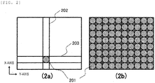
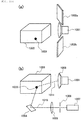
- Fig. 2 is a diagram illustrating the basic configuration of a magnetic field generator according to the present embodiment.
- Techniques for applying a magnetic field include a technique illustrated in (2a) for applying a magnetic field to a spot at a particular location and a technique illustrated in (2b) for applying a planar magnetic field throughout a predetermined region.
- an electromagnet 201 includes an X-axis movement adjusting mechanism 202 and a Y-axis movement adjusting mechanism 203. The position of the electromagnet 201 on the X-Y plane can be freely changed by using the X-axis movement adjusting mechanism 202 and the Y-axis movement adjusting mechanism 203.
- a plurality of electromagnets 201 are arranged on the X-Y plane, and thus magnetic force can be applied by the electromagnets 201 arranged in a desired region.
- the size of the electromagnet 201 is not limited.
- cells magnetized by incorporating a magnetic substance hereinafter simply referred to as "magnetized cells" are manipulated by using the electromagnet 201. Therefore, in order to improve the positional accuracy during cell manipulation, it is desirable to select small electromagnets 201.
- the positional accuracy during cell manipulation is relatively high and reproducibility of a three-dimensional structure from cells can be improved.
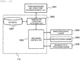
- Fig. 18 is a functional block diagram of determining fabrication conditions for a three-dimensional structure from cells according to the present embodiment.
- a fabrication condition acquiring unit 1802 acquires optimal fabrication conditions for the three-dimensional structure based on the input information and information stored in a database 1807 (various information including characteristics such as adhesion conditions according to types of cells, time restriction of fabrication, types and characteristics of magnetic beads, and the like).
- a mechanism control unit 1803 transmits instruction signals to an image processing engine 1804, an arm processing engine 1805, and a magnetic field processing engine 1806 in order to start fabrication operation based on the acquired conditions.
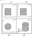
- Fig. 19 is a diagram illustrating fabrication images of a three-dimensional structure from cells according to the present embodiment.
- the operator can visually confirm images of a three-dimensional structure from cells in an X-Z plane 1901, a Y-Z plane 1902, an X-Y plane 1903, and an XYZ space 1904 displayed on the GUI of the display unit 111.
- the operator can design an image of a three-dimensional structure with a desired size and a desired thickness by adjusting lengths of horizontal axes and vertical axes in each of the planes 1901 to 1903.
- a fabrication image may be selectively displayed among any one of them.
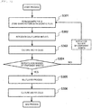
- Fig. 3 is a flowchart illustrating basic operation for fabricating a three-dimensional structure cells according to the present embodiment
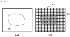
- Fig. 4 is a diagram illustrating an example of a magnetic field formation pattern according to the present embodiment.
- a magnetic field application pattern 403 set similarly to the target shape is applied (step S301).
- the magnetic field generator 104 employs the technique illustrated in (2b) for applying a planar magnetic field throughout a predetermined region.
- the magnetic field is applied only by the electromagnet 201 in a region included in the magnetic field application pattern 403 set similarly to the target shape (shape pattern) 402 of the cell mass through the magnetic field processing engine 106.
- the electromagnet 201 is preferably a solenoid coil capable of controlling a magnetic flux perpendicular to a surface with a current value.
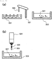
- Fig. 5 illustrates an example of an operation for introducing cells into a culture vessel.
- Fig. 5(a) a method of introducing individual spheroid cells 507 cultured in a well plate 502 into the culture vessel 503 by using an arm 501 is illustrated.
- the cell diameter of the individual spheroid cells 507 cultured in the well plate 502 is as uniform as possible.
- the individual spheroid cells 507 cultured in the well plate 502 may be reliably transferred to the culture vessel 503 one by one in order to reduce damages to cells .
- a plurality of spheroid cells 507 may be introduced into the culture vessel 503 during a single suction operation of a nozzle 508.
- the electromagnet 201 may be installed at the leading end of the nozzle 508, and the spheroid cell 507 may be manipulated by using a magnetic field and introduced into the culture vessel 503.
- the cultured spheroid cell 507 of the number equal to the number of the cells constituting the single layer cell sheet may be collected in a container like a centrifuge tube 504, and the optimal number of the spheroid cells 507 for forming the target shape 402 of a cell mass may be introduced into the culture vessel 503 by using a tube 505 and a valve 506 provided in the centrifuge tube 504.
- the introduction may be performed after the spheroid cells 507 are condensed at the bottom of the centrifuge tube 504 by centrifuging the centrifuge tube 504 including a large number of spheroid cells 507 or, when a magnetic substance is incorporated in the spheroid cells 507, by using an external magnetic field.
- Fig. 6 illustrates a state (a) of single layer cells at the beginning of culturing (before fixed) and a state (b) of the single layer cells after culturing (fixed) according to the present embodiment.
- cells incorporating a magnetic substance are arranged in a single layer shape.
- Fig. 6(a) when optimum temperature, oxygen concentration, and carbon dioxide concentration are given within the incubator 101, among cells 601 arranged in a single layer shape, as illustrated in Fig. 6(b) , individual spheroid cells are fused with one another and fixed, and thus a single layer cell sheet 602 is formed.
- step S304 it is determined about cell sheets 605 transformed to single layer sheets, whether all of the number of cell sheets necessary for fabricating a target three-dimensional cell mass are formed (step S304).
- steps S301 and S302 are repeated to form the necessary numbers of single layer cell sheets.
- Fig. 7 illustrates a process for making multilayered cells according to the present embodiment.
- step S304 all of the single layer cell sheets formed in step S304 are arranged as multilayer 709 (step S701) .
- step S702 When the single layer cell sheets are cultured by giving optimum temperature, oxygen concentration, and carbon dioxide concentration in the incubator 101 (step S702), individual single layer cell sheets are fused with one another and fixed, and thus a target cell mass 710 is formed (step S703) .
- a method of the manipulating a multilayer includes stacking the individual single layer cell sheets by using the arm 501.
- all of the single layer cell sheets formed in step S304 are arranged in respective culture vessels 103 prepared as many as the number of single layer cell sheets or in spaces elsewhere within one culture vessel 103. For this reason, the method of Fig.
- Fig. 7(b) there is an alternative method illustrated in Fig. 7(b) capable of making a multilayer with the culture vessel 103 having at least an area corresponding to an area of one single layer cell sheet.
- the magnetic field generator 104 applies a magnetic field pattern for a new layer onto the single layer cell sheet 712 formed in step S303 in the culture vessel 103, and as illustrated in Fig. 5 , cells are introduced into the culture vessel 103, thereby arranging a new cell layer having a shape of a single layer cell sheet through a magnetic field (step S704).
- step S705 when cultured in the incubator 101 by giving optimum temperature, oxygen concentration, and carbon dioxide concentration (step S705), a second layer cell sheet is fused and fixed, thereby forming cell mass 713 of two layers (step S706).
- steps S704, S705, and S706 described above a cell mass having the same shape as the cell mass formed using the method illustrated in Fig. 7(a) can be formed.
- Fig. 7(b) if there is the culture vessel 103 having at least an area corresponding to the area of one single layer cell sheet, multilayer can be made, and thus the size of a fabrication device can be further reduced.
- Fig. 20 is a diagram illustrating a GUI screen displaying information about a three-dimensional structure from cells according to the present embodiment.
- a shape image display unit 2001 displays an image of a three-dimensional structure from cells designed using the method described above with reference to Fig. 19 .
- the operator can input conditions including a name of used cell, a molding method (a single layer fixation, a single cell fixation, or the like), a molding mode (short time mode, highly-reproducible shape mode, or the like), and the like which are determined based on a purpose of a three-dimensional structure to be fabricated or a tissue to be applied through a molding condition input unit 2002.
- an optimum molding condition display unit 2003 the optimum conditions acquired by the fabrication condition acquiring unit 1802 described above with reference to Fig. 18 are displayed and, when starting a molding process under displayed conditions, the operator may instruct to start the molding process through an input button indicated as "mold under above conditions".
- Input and confirmation of fabrication conditions of a three-dimensional structure through the GUI screen can also be applied to an Embodiment 2 and an Embodiment 3 described below.
- step S302 a case of introducing cells of the number equal to the number of cells constituting a single layer cell sheet into the culture vessel 103 at once (step S302) has been described.
- step S302 a case of introducing cells of the number equal to the number of cells constituting a single layer cell sheet into the culture vessel 103 at once.
- fabrication of a three-dimensional structure from cells using a technique of introducing cells one by one into the culture vessel 103 will be described with reference to Figs. 8 to 12 .
- Fig. 8 is a flowchart illustrating operations for fabricating a three-dimensional structure from cells according to the present embodiment.
- cells are introduced into the culture vessel 103 one by one (step S801) .
- a control unit sets target location in the culture vessel 103 where cells will be arranged and move the cells to the target location in order to fabricate a desired three-dimensional structure.
- the magnetic field generator 104 employs the technique illustrated in (2a) of moving the electromagnet 201 toward a target location by using the X-axis movement adjusting mechanism 202 and the Y-axis movement adjusting mechanism 203 and applying a magnetic field to a particular spot.
- FIG. 9 illustrates an operation for introducing cells into a culture vessel according to the present embodiment.
- Fig. 9(a) there is a method of introducing each spheroid cell 904 cultured in a well plate 902 into a culture vessel 903 by using an arm 901.
- the cell diameter of the individual spheroid cells 904 cultured in the well plate 902 is as uniform as possible.
- an electromagnet may be installed at the leading end of a nozzle 907 and the spheroid cell 904 can be introduced into the culture vessel 903 after manipulating the spheroid cell 904 by using a magnetic field.
- Fig. 10 illustrates an example of determining locations of cells by using a camera according to the present embodiment.
- a camera 1001 and a lighting plate 1002 by using a camera 1001 and a lighting plate 1002, light reflected by the lighting plate 1002 is captured by using the camera 1001, and thus the relative locations of cells 1009 with respect to the culture vessel 1003 can be measured.
- the cells 1009 are stained with a fluorescent dye, a monochromatic light source 1007 such as a laser is used as excitation light in the culture vessel 1003, and excitation light source is scanned in the culture vessel 1003 by using a movable mirror 1004. Therefore, the locations of the cell 1009 emitting fluorescent light can be determined with the camera 1001. In this method, since light source is three-dimensionally scanned by using the movable mirror 1004, locations of cells can be effectively determined by using an appropriate pinhole 1006 and a lens 1005 to make an excitation light source as a confocal system.
- a correction coefficient is determined based on an amount of divergence from true values of the values measured by the camera 1001 of the calibrator, and calibration of the location of the camera 1001 can be performed.
- step S803 cells are manipulated by applying a magnetic field (step S803), and locations of the cells are measured by using the camera 1001 (step S804). Next, it is determined whether the measured locations of the cells are identical to target locations (step S805).
- Fig. 11 illustrates a specific example of a magnetic field formation pattern according to the present embodiment.
- Fig. 11(a) illustrates an example of an operation for moving a cell 1103 in a culture vessel 1101 to a destination point 1104 by using a magnetic field generated by a magnetic field generator 1102 outside the culture vessel 1101.
- equation 6 not only displacement of cells incorporating a magnetic substance can be controlled with a current value and an application time, but also an optimum current value and an optimum application time until cells arrive at destination points can be calculated.
- cells are controlled by an external magnetic field for a certain distance by applying a current in a pulsed manner (step S803), locations of the cells are checked with the camera 1001 (step S804), the cells can be manipulated again based on the measured locations of the cells (step S805). Furthermore, in step S804, if it is determined based on a result of image captured by the camera 1001 that a moving distance per pulse at the current value used until now is too large with respect to a distance to the destination point 1004, conditions can be adjusted to lower the current value for next cell movement, and thus cells can be manipulated with smaller moving distance per pulse. Therefore, the cells can be reliably moved to the destination point 1004.
- step S804 if it is determined that a movement amount per pulse passed the destination point 1004, the current value applied to the solenoid coil may be reversed in a next cell manipulation, thereby reversing a direction of the magnetic field and moving the cells to the destination point 1004. Since it is necessary to manipulate the cells 1103 incorporating a magnetic substance three-dimensionally inside of the culture vessel 1101 as in the present embodiment, it is preferable to install the magnetic field generators 1102 in three directions such as the X-axis direction, the Y-axis direction, and the Z-axis direction for more precise cell manipulation.
- step S806 the cells introduced into the culture vessel 103 are cultured and fixed.
- Fig. 12 illustrates the state (a) at the beginning of culturing (before fixed) and the state (b) after culturing (fixed) of single layer or multilayer cells according to the present embodiment.
- the method illustrated in Fig. 12(a) of fixing cells from edges or the method illustrated in Fig. 12 (b) of fixing cells from the center with respect to the target shape 1208 of a cell mass may be used.
- the method illustrated in Fig. 12 (a) is useful for cases such as tissue regeneration for a simple tissue where the highest priority is given to the shape thereof.
- the method illustrated in Fig. 12(b) is useful for cases such as organ regeneration when the highest priority is given to internal functions of internal organs.
- single layer cell sheets can be formed by one cell and a next single layer cell sheet can be formed thereon as described above in the Embodiment 1.
- a three-dimensional cell mass can be formed as a core first and cells can be formed around the core. It is desirable to employ an optimal method according to conditions of a three-dimensional structure from cells to be fabricated.
- Embodiment 1 and Embodiment 2 described above examples of fabrication of three-dimensional structures from cells where the diameter of used cells is uniform are illustrated. However, in order to improve the reproducibility of the shape of an organ formed by a three-dimensional structure from cells, it is sometimes necessary to use several cells with different diameters. In the present embodiment, fabrication of a three-dimensional structure from a plurality of cells having different diameters will be described with reference to Figs. 13 and 14 .
- Fig. 13 is a flowchart illustrating basic operation for fabricating a three-dimensional structure from a plurality of cells having different diameters according to the present embodiment
- Fig. 14 is a diagram illustrating states from the beginning of culturing to fixation of cells according to the present embodiment.
- step S1401 the interior image of the culture vessel 103 is captured (step S1301) and, from a result of the image capturing, a target shape of a cell mass and an image of a cell mass fixed until previous steps are extracted from the result of the image capturing. Based on the extracted result, a cell diameter necessary for a next step is calculated (step S1302).
- step S1402 cells having the cell diameter determined in step S1302 are introduced into the culture vessel 103.
- step S1403 the interior image of the culture vessel 103 is captured (step S1304) and, as in the Embodiment 2, image capturing with the camera 1001 and manipulation of cells using a magnetic field are repeatedly performed(steps S1304, S1305, and S1306), thereby manipulating the cells to target locations and fixing the cells thereto. As a result, a cell mass is formed.
- the present embodiment it is possible to significantly reduce the time required to form a cell mass by using cells having a large diameter for a part that includes cells of a same type and occupies a large volume. Also, by using cells having small diameters for a part with a complicated shape, shape reproducibility of the cell mass can be improved.
- a three-dimensional cell structure is fabricated without removing magnetic substances from magnetized cells.
- an incorporated magnetic substance can be naturally discharged by the metabolism of the cells. In such a case, even if a process for removing the magnetic substances is not performed, it is thought that there is no influence from the magnetic substances.
- natural discharge of a magnetic substance may be insufficient.
- Figs. 15 and 16 are flowcharts illustrating basic operations of embodiments in which a process for removing magnetic beads according to the present embodiment is added to the fabrications of three-dimensional structures from cells described above in the Embodiments 1 and 2, respectively.
- a magnetic substance removal operation step S1504
- a magnetic substance removal operation step S1609
- Fig. 17 is a flowchart illustrating details of a magnetic bead removing process according to the present embodiment.
- the thickness of a cell sheet or the diameter of cells is measured by the camera 1001.
- the thickness of the cell sheet is measured.
- the diameter of the cells is measured (step S1701).
- the conditions (temperature, time, and the like) for removing a magnetic substance are acquired (step S1702), considering the type of the cells and the magnetic substances, based on the information including the diameter of the cells or the thickness of a cell sheet measured in step S1701.
- step S1703 by using the magnetic substance removal conditions determined in step S1702, the metabolic activator or the like is applied to the cells, thereby removing the magnetic substance (step S1703).
- step S1704 it is determined whether the magnetic substance is reliably removed through the removal process in step S1703 (step S1704). Specifically, several single cells are arranged as controls in the culture vessel 103, and locations of the cells are measured with the camera 1001 when an external magnetic field is generated by the magnetic field generator 104 with respect to the controls. Therefore, it may be determined whether the magnetic substance is removed. By performing the above removal process, it becomes possible to reliably remove a magnetic substance and to fabricate a three-dimensional structure guaranteeing high safety in any circumstances.
- Fig. 21 is a diagram illustrating a GUI screen displaying information about a three-dimensional structure from cells according to the present embodiment.
- a shape image display unit 2101, a molding condition input unit 2102, and an optimum molding condition display unit 2103 are the same as the components described above with reference to Fig. 20 , respectively.
- the present embodiment includes a process for removing a magnetic substance, a magnetic bead condition input unit 2012-1 for inputting information necessary for setting conditions for the removal process, and a demagnetizing bead condition display unit 2103-1 for displaying required removal conditions based on the input information are further provided.
- a regenerated tissue/regenerated organ having a desired size, shape, or structure can be formed by adjusting culture conditions with high precision and without causing contamination or damage to cells.
- the present invention is not limited to the above embodiments, but includes various modified examples.
- the above embodiments have been described in detail in order to explain the present invention in an easy-to-understand manner, and are not necessarily limited to those having all the configurations described.
- a part of the configuration of one embodiment can be replaced with the configuration of another embodiment, and the configuration of another embodiment can be added to the configuration of one embodiment.
Landscapes
- Health & Medical Sciences (AREA)
- Life Sciences & Earth Sciences (AREA)
- Engineering & Computer Science (AREA)
- Chemical & Material Sciences (AREA)
- Bioinformatics & Cheminformatics (AREA)
- Organic Chemistry (AREA)
- Wood Science & Technology (AREA)
- Zoology (AREA)
- Biotechnology (AREA)
- Genetics & Genomics (AREA)
- Biomedical Technology (AREA)
- General Health & Medical Sciences (AREA)
- Microbiology (AREA)
- Biochemistry (AREA)
- General Engineering & Computer Science (AREA)
- Sustainable Development (AREA)
- Cell Biology (AREA)
- Physics & Mathematics (AREA)
- Thermal Sciences (AREA)
- Analytical Chemistry (AREA)
- Molecular Biology (AREA)
- Medicinal Chemistry (AREA)
- Apparatus Associated With Microorganisms And Enzymes (AREA)
- Micro-Organisms Or Cultivation Processes Thereof (AREA)
Abstract
Description
- The present invention relates to a technique for fabricating a three-dimensional structure from cells, and more particularly, to a device and a method for fabricating a three-dimensional structure having an arbitrary shape such as a cell mass by performing cell manipulation to cells such as spheroid cells incorporating a magnetic substance therein by using an external magnetic field.
- In recent years, with the development of regenerative medical technology, regenerated tissue and regenerated organ are demanded not only for research use, but also for therapeutic use in clinical practice.
- PTL 1 discloses a technique for manipulating cells (such as spheroid cells) and forming a cell mass having an arbitrary shape by culturing the spheroid cells in a state where the spheroid cells are skewered on needles in a shape of a pin holder.
- PTL 2 discloses a technique for forming a tissue by adhering cells to one another by generating a centrifugal force in a culture vessel for culturing cells or magnetizing cells with magnetic particles and generating a magnetic force from outside by using a magnet.
- PTL 3 discloses a technique for forming a multilayered tissue by culturing cells magnetized by magnetic particles in a state where the cells are attached to the bottom surface of a culture vessel by a magnetic force of a magnet.
-
- PTL 1:
WO 2008/123614 - PTL 2:
JP-A-2010-161954 - PTL 3:
WO 2004/083412 - When forming a regenerated tissue/regenerated organ having a desired size, shape, or structure by using cells collected from a living body, it is necessary to adjust culture conditions with high precision and without causing contamination or damage to cells.
- However, with the technique disclosed in PTL 1, during manipulation of cells, in order to form a cell mass having an arbitrary shape, cells are skewered directly to a plurality of needles in a shape of a pin holder. Therefore, damages to cells are not negligible, and there is also a risk of contamination.
- With the techniques described in PTL 2 and PTL 3, as described above, adhesion between cells and a culture vessel and adhesion between the cells are promoted by using a centrifugal force or a magnetic force from the outside, it is not necessary to directly contact the cells, and thus influence from contamination and damage can be reduced. However, no specific culturing method for forming a regenerated tissue/regenerated organ with a desired shape or size is taken into consideration.
- In view of the above-described problems, the present invention relates to realization of formation of a regenerated tissue/regenerated organ having a desired size, shape, or structure by adjusting culture conditions with high precision and without causing contamination or damage to cells.
- According to an aspect of the present invention, there is provided a device and a method using the device. The device includes a culture vessel in which magnetized cells are arranged; a magnetic field generator configured to generate a magnetic field in the culture vessel; an incubator configured to accommodate the culture vessel therein and maintain the interior of the culture vessel at a predetermined temperature; and a control unit configured to control culture conditions of cells arranged in the culture vessel, in which, when information about a three-dimensional structure to be fabricated is input from an operator, the control unit acquires fabrication condition for the corresponding three-dimensional structure based on the input information, and controls the magnetic field generator to generate a magnetic field based on the acquired fabrication conditions.
- According to the above aspect, a regenerated tissue/regenerated organ having a desired size, shape, or structure can be formed by adjusting culture conditions with high precision and without causing contamination or damage to cells.
-
-
Fig. 1 is a diagram illustrating a basic configuration of a device for fabricating a three-dimensional structure from cells according to the present embodiment. -
Fig. 2 is a diagram illustrating the basic configuration of a magnetic field generator according to the present embodiment. -
Fig. 3 is a flowchart illustrating basic operation for fabricating a three-dimensional structure from cells according to the present embodiment (Embodiment 1). -
Fig. 4 is a diagram illustrating an example of a magnetic field formation pattern according to the present embodiment (Embodiment 1). -
Fig. 5 is a diagram illustrating an example of an operation for introducing cells into a culture vessel according to the present embodiment (Embodiment 1). -
Fig. 6 is a diagram illustrating a state (a) of single layer cells at the beginning of culturing (before fixed) and a state (b) of the single layer cells after culturing (fixed) according to the present embodiment (Embodiment 1). -
Fig. 7 is a diagram illustrating a process for making multilayered cells according to the present embodiment (Embodiment 1). -
Fig. 8 is a flowchart illustrating basic operation for fabricating a three-dimensional structure from cells according to the present embodiment (Embodiment 2). -
Fig. 9 is a diagram illustrating an operation for introducing cells into a culture vessel according to the present embodiment (Embodiment 2). -
Fig. 10 is a diagram illustrating an example of checking locations of cells by using a camera according to the present embodiment (Embodiment 2). -
Fig. 11 is a diagram illustrating a specific example of a magnetic field formation pattern according to the present embodiment (Embodiment 2). -
Fig. 12 is a diagram illustrating a state (a) of single layer or multilayer cells at the beginning of culturing (before fixed) and a state (b) of the single layer or multilayer cells after culturing (fixed) according to the present embodiment (Embodiment 2). -
Fig. 13 is a flowchart illustrating basic operation for fabricating a three-dimensional structure from a plurality of cells with different diameters according to the present embodiment (Embodiment 3). -
Fig. 14 is a diagram illustrating states from the beginning of culturing to fixation of cells according to the present embodiment (Embodiment 3). -
Fig. 15 is a flowchart illustrating basic operation for fabricating a three-dimensional structure from cells, including a step of removing magnetic beads according to the present embodiment (Embodiment 4). -
Fig. 16 is a flowchart illustrating basic operation for fabricating a three-dimensional structure from cells, including a step of removing magnetic beads according to the present embodiment (Embodiment 4). -
Fig. 17 is a flowchart illustrating details of a step of removing magnetic beads according to the present embodiment (Embodiment 4). -
Fig. 18 is a functional block diagram of determining fabrication conditions for a three-dimensional structure from cells according to the present embodiment. -
Fig. 19 is a diagram illustrating fabrication images of a three-dimensional structure from cells according to the present embodiment. -
Fig. 20 is a diagram illustrating a GUI screen displaying information about a three-dimensional structure from cells according to the present embodiment (Embodiment 1 to Embodiment 3). -
Fig. 21 is a diagram illustrating a GUI screen displaying information about a three-dimensional structure from cells according to the present embodiment (Embodiment 4) . - Hereinafter, the present embodiment will be described below in detail with reference to the drawings. Throughout the description, redundant explanation may be omitted for each component having the same function in the drawings for describing the present embodiment.
-
Fig. 1 is a diagram illustrating a basic configuration of a device for fabricating a three-dimensional structure from cells according to the present embodiment. - The device of the present embodiment mainly includes a
culture vessel 103, anarm 102, amagnetic field generator 104, and acamera 105 in anincubator 101. The device of the present embodiment further includes a magneticfield processing engine 106, anarm processing engine 107, animage processing engine 108, adata bus 109, acontrol unit 110, adisplay unit 111, and aninput unit 112 that are outside theincubator 101. Theincubator 101 can adjust internal temperature, oxygen concentration, and carbon dioxide concentration therein. In order to capture a clear image, it is desirable for thecamera 105 to be installed in theincubator 101. However, when the internal temperature, the oxygen concentration, and the carbon dioxide concentration are inappropriate for capturing an image or in order to reduce the risk of contamination, thecamera 105 may be installed outside theincubator 101. - Furthermore, throughout the description, the
control unit 110 controls operation or condition setting/adjustment of various components included in the device of the description, such as adjustment of environmental conditions inside theincubator 101, operation of thearm 102, adjustment of magnetic field generation conditions by themagnetic field generator 104, and adjustment of image capturing operation and conditions using thecamera 105. Thecontrol unit 110 can exchange information with the magneticfield processing engine 106, thearm processing engine 107, and theimage processing engine 108 via thedata bus 109, thereby transmitting instructions to various components or acquiring data, such as signals and images acquired from various components. In addition, thecontrol unit 110 may acquire and store various types of data related to cell culture conditions and information including instructions input by an operator via the input unit 112 (a keyboard, a mouse, and the like), calculate conditions for fabricating a three-dimensional structure from cells described below, and display the above-stated information on thedisplay unit 111 for displaying a graphical user interface (GUI) or the like. Furthermore, inFig. 1 , thecontrol unit 110 is connected to each component and controls the entire device of the present embodiment. However, each component may include an independent control unit. - Next, the configuration of the above-stated
magnetic field generator 104 will be described below in more detail with reference toFig. 2 . -
Fig. 2 is a diagram illustrating the basic configuration of a magnetic field generator according to the present embodiment. Techniques for applying a magnetic field include a technique illustrated in (2a) for applying a magnetic field to a spot at a particular location and a technique illustrated in (2b) for applying a planar magnetic field throughout a predetermined region. In the technique illustrated in (2a), anelectromagnet 201 includes an X-axismovement adjusting mechanism 202 and a Y-axismovement adjusting mechanism 203. The position of theelectromagnet 201 on the X-Y plane can be freely changed by using the X-axismovement adjusting mechanism 202 and the Y-axismovement adjusting mechanism 203. In the technique illustrated in (2b), a plurality ofelectromagnets 201 are arranged on the X-Y plane, and thus magnetic force can be applied by theelectromagnets 201 arranged in a desired region. Here, the size of theelectromagnet 201 is not limited. However, in either the technique illustrated in (2a) or the technique illustrated in (2b), cells magnetized by incorporating a magnetic substance (hereinafter simply referred to as "magnetized cells") are manipulated by using theelectromagnet 201. Therefore, in order to improve the positional accuracy during cell manipulation, it is desirable to selectsmall electromagnets 201. In addition, when at least the diameter of theelectromagnets 201 is smaller than the diameter of magnetized cells, the positional accuracy during cell manipulation is relatively high and reproducibility of a three-dimensional structure from cells can be improved. - Here,
Fig. 18 is a functional block diagram of determining fabrication conditions for a three-dimensional structure from cells according to the present embodiment. When the operator inputs information about a desired three-dimensional structure to be fabricated (shape image, size, thickness, and the like) through a three-dimensional cell structureinformation input unit 1801 in theinput unit 112 illustrated inFig. 1 , a fabricationcondition acquiring unit 1802 acquires optimal fabrication conditions for the three-dimensional structure based on the input information and information stored in a database 1807 (various information including characteristics such as adhesion conditions according to types of cells, time restriction of fabrication, types and characteristics of magnetic beads, and the like). Thereafter, amechanism control unit 1803 transmits instruction signals to animage processing engine 1804, anarm processing engine 1805, and a magneticfield processing engine 1806 in order to start fabrication operation based on the acquired conditions. - Here,
Fig. 19 is a diagram illustrating fabrication images of a three-dimensional structure from cells according to the present embodiment. As illustrated inFig. 19 , the operator can visually confirm images of a three-dimensional structure from cells in anX-Z plane 1901, aY-Z plane 1902, anX-Y plane 1903, and anXYZ space 1904 displayed on the GUI of thedisplay unit 111. Furthermore, the operator can design an image of a three-dimensional structure with a desired size and a desired thickness by adjusting lengths of horizontal axes and vertical axes in each of theplanes 1901 to 1903. Here, in the present embodiment, a case of displaying fabrication images of a three-dimensional structure in all of theX-Z plane 1901, theY-Z plane 1902, theX-Y plane 1903, and theXYZ space 1904 is described. However, a fabrication image may be selectively displayed among any one of them. - Next, fabrication of a three-dimensional structure from cells using the above-described device will be described below with reference to
Figs. 3 to 7 andFig. 20 . -
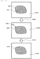
Fig. 3 is a flowchart illustrating basic operation for fabricating a three-dimensional structure cells according to the present embodiment, andFig. 4 is a diagram illustrating an example of a magnetic field formation pattern according to the present embodiment. - First, in the
magnetic field generator 104, based on a target shape (shape pattern) 402 of a cell mass illustrated inFig. 4 , a magneticfield application pattern 403 set similarly to the target shape is applied (step S301). In the present embodiment, themagnetic field generator 104 employs the technique illustrated in (2b) for applying a planar magnetic field throughout a predetermined region. - When applying a magnetic field, the magnetic field is applied only by the
electromagnet 201 in a region included in the magneticfield application pattern 403 set similarly to the target shape (shape pattern) 402 of the cell mass through the magneticfield processing engine 106. In this case, theelectromagnet 201 is preferably a solenoid coil capable of controlling a magnetic flux perpendicular to a surface with a current value. - Next, magnetized cells incorporating magnetic substances such as magnetic beads are introduced into the culture vessel 103 (step S302) as much as the number of cells constituting a single layer cell sheet. Here,
Fig. 5 illustrates an example of an operation for introducing cells into a culture vessel. Here, as illustrated inFig. 5(a) , a method of introducingindividual spheroid cells 507 cultured in awell plate 502 into theculture vessel 503 by using anarm 501 is illustrated. In order to improve the reproducibility of a single layer cell sheet, it is preferable that the cell diameter of theindividual spheroid cells 507 cultured in thewell plate 502 is as uniform as possible. In this case, theindividual spheroid cells 507 cultured in thewell plate 502 may be reliably transferred to theculture vessel 503 one by one in order to reduce damages to cells . Furthermore, in order to improve the efficiency of introduction, a plurality ofspheroid cells 507 may be introduced into theculture vessel 503 during a single suction operation of anozzle 508. In step S302, when a magnetic substance is incorporated in thespheroid cell 507, theelectromagnet 201 may be installed at the leading end of thenozzle 508, and thespheroid cell 507 may be manipulated by using a magnetic field and introduced into theculture vessel 503. Alternatively, as illustrated inFig. 5(b) , the culturedspheroid cell 507 of the number equal to the number of the cells constituting the single layer cell sheet may be collected in a container like acentrifuge tube 504, and the optimal number of thespheroid cells 507 for forming thetarget shape 402 of a cell mass may be introduced into theculture vessel 503 by using atube 505 and avalve 506 provided in thecentrifuge tube 504. In this case, in order to complete the introduction within a short period of time, the introduction may be performed after thespheroid cells 507 are condensed at the bottom of thecentrifuge tube 504 by centrifuging thecentrifuge tube 504 including a large number ofspheroid cells 507 or, when a magnetic substance is incorporated in thespheroid cells 507, by using an external magnetic field. - Next, cells introduced into the
culture vessel 103 are cultured and fixed (step S303) . - Here,
Fig. 6 illustrates a state (a) of single layer cells at the beginning of culturing (before fixed) and a state (b) of the single layer cells after culturing (fixed) according to the present embodiment. According to themagnetic field pattern 403 applied in step S301, cells incorporating a magnetic substance are arranged in a single layer shape. As illustrated inFig. 6(a) , when optimum temperature, oxygen concentration, and carbon dioxide concentration are given within theincubator 101, amongcells 601 arranged in a single layer shape, as illustrated inFig. 6(b) , individual spheroid cells are fused with one another and fixed, and thus a singlelayer cell sheet 602 is formed. - Next, in step S304, it is determined about cell sheets 605 transformed to single layer sheets, whether all of the number of cell sheets necessary for fabricating a target three-dimensional cell mass are formed (step S304). Here, when not all numbers of sheets necessary are formed, steps S301 and S302 are repeated to form the necessary numbers of single layer cell sheets.
- When all the necessary single layer cell sheets are formed, the process proceeds to a multilayer process (step S305) . Here,
Fig. 7 illustrates a process for making multilayered cells according to the present embodiment. - As illustrated in
Fig. 7 (a) , all of the single layer cell sheets formed in step S304 are arranged as multilayer 709 (step S701) . When the single layer cell sheets are cultured by giving optimum temperature, oxygen concentration, and carbon dioxide concentration in the incubator 101 (step S702), individual single layer cell sheets are fused with one another and fixed, and thus atarget cell mass 710 is formed (step S703) . Here, a method of the manipulating a multilayer includes stacking the individual single layer cell sheets by using thearm 501. Furthermore, all of the single layer cell sheets formed in step S304 are arranged inrespective culture vessels 103 prepared as many as the number of single layer cell sheets or in spaces elsewhere within oneculture vessel 103. For this reason, the method ofFig. 7(a) requires theculture vessel 103 having a large area or a large volume, and thus the size of a fabrication device may become inevitably large. Therefore, there is an alternative method illustrated inFig. 7(b) capable of making a multilayer with theculture vessel 103 having at least an area corresponding to an area of one single layer cell sheet. As illustrated inFig. 7(b) , themagnetic field generator 104 applies a magnetic field pattern for a new layer onto the singlelayer cell sheet 712 formed in step S303 in theculture vessel 103, and as illustrated inFig. 5 , cells are introduced into theculture vessel 103, thereby arranging a new cell layer having a shape of a single layer cell sheet through a magnetic field (step S704). Next, when cultured in theincubator 101 by giving optimum temperature, oxygen concentration, and carbon dioxide concentration (step S705), a second layer cell sheet is fused and fixed, thereby formingcell mass 713 of two layers (step S706). By repeating steps S704, S705, and S706 described above, a cell mass having the same shape as the cell mass formed using the method illustrated inFig. 7(a) can be formed. Furthermore, in the method ofFig. 7(b) , if there is theculture vessel 103 having at least an area corresponding to the area of one single layer cell sheet, multilayer can be made, and thus the size of a fabrication device can be further reduced. - Here,
Fig. 20 is a diagram illustrating a GUI screen displaying information about a three-dimensional structure from cells according to the present embodiment. A shapeimage display unit 2001 displays an image of a three-dimensional structure from cells designed using the method described above with reference toFig. 19 . In addition, the operator can input conditions including a name of used cell, a molding method (a single layer fixation, a single cell fixation, or the like), a molding mode (short time mode, highly-reproducible shape mode, or the like), and the like which are determined based on a purpose of a three-dimensional structure to be fabricated or a tissue to be applied through a moldingcondition input unit 2002. Then, in an optimum moldingcondition display unit 2003, the optimum conditions acquired by the fabricationcondition acquiring unit 1802 described above with reference toFig. 18 are displayed and, when starting a molding process under displayed conditions, the operator may instruct to start the molding process through an input button indicated as "mold under above conditions". - Input and confirmation of fabrication conditions of a three-dimensional structure through the GUI screen can also be applied to an Embodiment 2 and an Embodiment 3 described below.
- In the Embodiment 1 described above, a case of introducing cells of the number equal to the number of cells constituting a single layer cell sheet into the
culture vessel 103 at once (step S302) has been described. Next, in the present embodiment, in order to further improve the reproducibility of a single layer cell sheet, fabrication of a three-dimensional structure from cells using a technique of introducing cells one by one into theculture vessel 103 will be described with reference toFigs. 8 to 12 . -
Fig. 8 is a flowchart illustrating operations for fabricating a three-dimensional structure from cells according to the present embodiment. First, cells are introduced into theculture vessel 103 one by one (step S801) . At this time, based on information input by an operator as described above, a control unit sets target location in theculture vessel 103 where cells will be arranged and move the cells to the target location in order to fabricate a desired three-dimensional structure. In the present embodiment, themagnetic field generator 104 employs the technique illustrated in (2a) of moving theelectromagnet 201 toward a target location by using the X-axismovement adjusting mechanism 202 and the Y-axismovement adjusting mechanism 203 and applying a magnetic field to a particular spot. - Here,
Fig. 9 illustrates an operation for introducing cells into a culture vessel according to the present embodiment. As illustrated inFig. 9(a) , there is a method of introducing eachspheroid cell 904 cultured in awell plate 902 into aculture vessel 903 by using anarm 901. - In order to improve the reproducibility of a cell mass, it is preferable that the cell diameter of the
individual spheroid cells 904 cultured in thewell plate 902 is as uniform as possible. In the case where a magnetic substance is incorporated in thespheroid cell 904 at the time of step S801, an electromagnet may be installed at the leading end of anozzle 907 and thespheroid cell 904 can be introduced into theculture vessel 903 after manipulating thespheroid cell 904 by using a magnetic field. Alternatively, as illustrated inFig. 9(b) , there is a technique of introducing theindividual spheroid cells 904 cultured in thewell plate 902 into theculture vessel 903 through atube 905 and avalve 906 connected to thewell plate 902. In this case, after confirming with thecamera 105 that introduced cells are fixed at locations (target locations) to be arranged to fabricate a three-dimensional structure, thevalve 906 for next cells can be opened for cell introduction. Accordingly, since there are no contact objects such as thearm 901 when cells are introduced, cells can be introduced with a minimum risk of contamination. - Next, the locations of the introduced cells are determined (step S802) . Here,
Fig. 10 illustrates an example of determining locations of cells by using a camera according to the present embodiment. In the method illustrated inFig. 10 (a) , by using acamera 1001 and a lighting plate 1002, light reflected by the lighting plate 1002 is captured by using thecamera 1001, and thus the relative locations ofcells 1009 with respect to theculture vessel 1003 can be measured. Here, in order to minimize the influence of halation between a surface of theculture vessel 1003 and thecamera 1001, it is desirable to use twolighting plates Fig. 10(a) . - In addition, in the method illustrated in
Fig. 10(b) , in order to determine locations of cells, thecells 1009 are stained with a fluorescent dye, a monochromaticlight source 1007 such as a laser is used as excitation light in theculture vessel 1003, and excitation light source is scanned in theculture vessel 1003 by using amovable mirror 1004. Therefore, the locations of thecell 1009 emitting fluorescent light can be determined with thecamera 1001. In this method, since light source is three-dimensionally scanned by using themovable mirror 1004, locations of cells can be effectively determined by using anappropriate pinhole 1006 and alens 1005 to make an excitation light source as a confocal system. - In the methods illustrated in
Figs. 10(a) and 10(b) , since it is necessary to determine locations of cells in the three-dimensional space inside theculture vessel 1003, it is effective to install thecameras 1001 in three directions such as the X-axis direction, the Y-axis direction, and the Z-axis direction for more accurate determination of the locations of cells. Furthermore, when relative locations of thecamera 1001 and theculture vessel 1003 are changed, fluctuation of locations of cells can be minimized by performing a calibration of relative positions. Specifically, for example, by using a calibrator that determines absolute positions with an inactive substance during a cell culturing process in theculture vessel 1003, a correction coefficient is determined based on an amount of divergence from true values of the values measured by thecamera 1001 of the calibrator, and calibration of the location of thecamera 1001 can be performed. - Next, cells are manipulated by applying a magnetic field (step S803), and locations of the cells are measured by using the camera 1001 (step S804). Next, it is determined whether the measured locations of the cells are identical to target locations (step S805).
- Here,
Fig. 11 illustrates a specific example of a magnetic field formation pattern according to the present embodiment.Fig. 11(a) illustrates an example of an operation for moving acell 1103 in aculture vessel 1101 to adestination point 1104 by using a magnetic field generated by amagnetic field generator 1102 outside theculture vessel 1101. In general, themagnetic field generator 1102 employs theelectromagnet 201 capable of freely controlling a magnetic field using an electric current, and a magnetic field H generated by a representative solenoid coil therein may be expressed by an Equation (1) : H = n · I (n: the number of times coils is wound, I: a current value). Subsequently, a force F[N] generated when a magnetic pole of m[Wb] is arranged in the magnetic field H can be expressed as (Equation 2): F = m · H. - The two equations stated above can be combined with each other and expressed as (Equation 3) : F = m · n · I, and a cell incorporating a magnetic substance of m[Wb] can apply an external force based on a current value. Next, when a force of F[N] is applied to a material having a mass of M[kg], an acceleration a[m/s^2] can be expressed as (Equation 4): a = F/M. Then, a displacement x of an object moving with the acceleration a[m/s^2] after t[s] at the initial velocity of 0 can be expressed as (Equation 5) : x = (1/2) · a · (t)^2, based on (Equation 3), (Equation 4), and (Equation 5), (Equation 6) can be expressed as x = (m · n/2M) · I · t^2. Here, according to (Equation 6), not only displacement of cells incorporating a magnetic substance can be controlled with a current value and an application time, but also an optimum current value and an optimum application time until cells arrive at destination points can be calculated.
- Furthermore, as illustrated in
Fig. 11(b) , cells are controlled by an external magnetic field for a certain distance by applying a current in a pulsed manner (step S803), locations of the cells are checked with the camera 1001 (step S804), the cells can be manipulated again based on the measured locations of the cells (step S805). Furthermore, in step S804, if it is determined based on a result of image captured by thecamera 1001 that a moving distance per pulse at the current value used until now is too large with respect to a distance to thedestination point 1004, conditions can be adjusted to lower the current value for next cell movement, and thus cells can be manipulated with smaller moving distance per pulse. Therefore, the cells can be reliably moved to thedestination point 1004. - Next, in step S804, as illustrated in
Fig. 11(c) , if it is determined that a movement amount per pulse passed thedestination point 1004, the current value applied to the solenoid coil may be reversed in a next cell manipulation, thereby reversing a direction of the magnetic field and moving the cells to thedestination point 1004. Since it is necessary to manipulate thecells 1103 incorporating a magnetic substance three-dimensionally inside of theculture vessel 1101 as in the present embodiment, it is preferable to install themagnetic field generators 1102 in three directions such as the X-axis direction, the Y-axis direction, and the Z-axis direction for more precise cell manipulation. - Next, the cells introduced into the
culture vessel 103 are cultured and fixed (step S806). - Here,
Fig. 12 illustrates the state (a) at the beginning of culturing (before fixed) and the state (b) after culturing (fixed) of single layer or multilayer cells according to the present embodiment. In the present embodiment, when cells are manipulated one by one, either the method illustrated inFig. 12(a) of fixing cells from edges or the method illustrated inFig. 12 (b) of fixing cells from the center with respect to thetarget shape 1208 of a cell mass may be used. - The method illustrated in
Fig. 12 (a) is useful for cases such as tissue regeneration for a simple tissue where the highest priority is given to the shape thereof. Also, the method illustrated inFig. 12(b) is useful for cases such as organ regeneration when the highest priority is given to internal functions of internal organs. In any of the methods illustrated inFigs. 12(a) and 12(b) , as an order for fixing cells, single layer cell sheets can be formed by one cell and a next single layer cell sheet can be formed thereon as described above in the Embodiment 1. Alternatively, a three-dimensional cell mass can be formed as a core first and cells can be formed around the core. It is desirable to employ an optimal method according to conditions of a three-dimensional structure from cells to be fabricated. - In Embodiment 1 and Embodiment 2 described above, examples of fabrication of three-dimensional structures from cells where the diameter of used cells is uniform are illustrated. However, in order to improve the reproducibility of the shape of an organ formed by a three-dimensional structure from cells, it is sometimes necessary to use several cells with different diameters. In the present embodiment, fabrication of a three-dimensional structure from a plurality of cells having different diameters will be described with reference to
Figs. 13 and14 . -
Fig. 13 is a flowchart illustrating basic operation for fabricating a three-dimensional structure from a plurality of cells having different diameters according to the present embodiment, andFig. 14 is a diagram illustrating states from the beginning of culturing to fixation of cells according to the present embodiment. - First, in step S1401, the interior image of the
culture vessel 103 is captured (step S1301) and, from a result of the image capturing, a target shape of a cell mass and an image of a cell mass fixed until previous steps are extracted from the result of the image capturing. Based on the extracted result, a cell diameter necessary for a next step is calculated (step S1302). - Next, in step S1402, cells having the cell diameter determined in step S1302 are introduced into the
culture vessel 103. Next, in step S1403, the interior image of theculture vessel 103 is captured (step S1304) and, as in the Embodiment 2, image capturing with thecamera 1001 and manipulation of cells using a magnetic field are repeatedly performed(steps S1304, S1305, and S1306), thereby manipulating the cells to target locations and fixing the cells thereto. As a result, a cell mass is formed. - According to the present embodiment, it is possible to significantly reduce the time required to form a cell mass by using cells having a large diameter for a part that includes cells of a same type and occupies a large volume. Also, by using cells having small diameters for a part with a complicated shape, shape reproducibility of the cell mass can be improved.
- In the above-described embodiments, a three-dimensional cell structure is fabricated without removing magnetic substances from magnetized cells. Depending on types of cells and magnetic substances, an incorporated magnetic substance can be naturally discharged by the metabolism of the cells. In such a case, even if a process for removing the magnetic substances is not performed, it is thought that there is no influence from the magnetic substances. However, depending on types of cells, types of magnetic substances, and sizes of cells, natural discharge of a magnetic substance may be insufficient. Also, depending on purposes of a cell mass, it may be necessary to remove a magnetic substance reliably when the cell mass is used for transplantation into a body, for example, clinical use. In such a case, it is necessary to reliably remove a magnetic substance in cells through an external manipulation.
- In the present embodiment, embodiments in which a process for removing a magnetic substance in a cell is included after formation of a three-dimensional structure by using cells incorporating the magnetic substance according to the Embodiments 1 and 2 will be described with reference to
Figs. 15 to 17 , andFig. 21 . -
Figs. 15 and16 are flowcharts illustrating basic operations of embodiments in which a process for removing magnetic beads according to the present embodiment is added to the fabrications of three-dimensional structures from cells described above in the Embodiments 1 and 2, respectively. In the flowchart ofFig. 15 , after formation of a single layer cell sheet (step S1503), a magnetic substance removal operation (step S1504) is performed. Also, in the flowchart ofFig. 16 , after fixation of one cell (step S1608), a magnetic substance removal operation (step S1609) is performed. -
Fig. 17 is a flowchart illustrating details of a magnetic bead removing process according to the present embodiment. - First, the thickness of a cell sheet or the diameter of cells is measured by the
camera 1001. In case of applying the Embodiment 1, the thickness of the cell sheet is measured. In case of applying the Embodiment 2, the diameter of the cells is measured (step S1701). During an operation for removing the magnetic substances, when the thickness of the cell sheet or the diameter of cells is large, if a metabolic activator or the like is applied for promoting discharge of the magnetic substances, it is difficult for the activator to reach the cells in the center portion of the cell sheet. Therefore, by acquiring such information in the present step, various conditions (temperature, time, and the like) for reliably transferring the activators to the center portion can be optimally set. - The conditions (temperature, time, and the like) for removing a magnetic substance are acquired (step S1702), considering the type of the cells and the magnetic substances, based on the information including the diameter of the cells or the thickness of a cell sheet measured in step S1701.
- Next, by using the magnetic substance removal conditions determined in step S1702, the metabolic activator or the like is applied to the cells, thereby removing the magnetic substance (step S1703).
- Thereafter, in step S1704, it is determined whether the magnetic substance is reliably removed through the removal process in step S1703 (step S1704). Specifically, several single cells are arranged as controls in the
culture vessel 103, and locations of the cells are measured with thecamera 1001 when an external magnetic field is generated by themagnetic field generator 104 with respect to the controls. Therefore, it may be determined whether the magnetic substance is removed. By performing the above removal process, it becomes possible to reliably remove a magnetic substance and to fabricate a three-dimensional structure guaranteeing high safety in any circumstances. - Here,
Fig. 21 is a diagram illustrating a GUI screen displaying information about a three-dimensional structure from cells according to the present embodiment. - In
Fig. 21 , a shapeimage display unit 2101, a moldingcondition input unit 2102, and an optimum moldingcondition display unit 2103 are the same as the components described above with reference toFig. 20 , respectively. However, since the present embodiment includes a process for removing a magnetic substance, a magnetic bead condition input unit 2012-1 for inputting information necessary for setting conditions for the removal process, and a demagnetizing bead condition display unit 2103-1 for displaying required removal conditions based on the input information are further provided. - As described above, according to the present embodiment described above, a regenerated tissue/regenerated organ having a desired size, shape, or structure can be formed by adjusting culture conditions with high precision and without causing contamination or damage to cells.
- It should be noted that the present invention is not limited to the above embodiments, but includes various modified examples. For example, the above embodiments have been described in detail in order to explain the present invention in an easy-to-understand manner, and are not necessarily limited to those having all the configurations described. Further, a part of the configuration of one embodiment can be replaced with the configuration of another embodiment, and the configuration of another embodiment can be added to the configuration of one embodiment. Further, it is possible to add, delete, and replace other configurations with respect to a part of configuration of each embodiment.
-
- 101: incubator
- 102: arm
- 103: culture vessel
- 104: magnetic field generator
- 105: camera
- 106: magnetic field processing engine
- 107: arm processing engine
- 108: image processing engine
- 109: data bus
- 110: control unit
- 111: display unit
- 112: input unit
- 201: electromagnet
- 202: X-axis movement adjusting mechanism
- 203: Y-axis movement adjusting mechanism
- 401: external magnetic field generator
- 402: target shape of cell mass (shape pattern)
- 403: magnetic field application pattern
- 501: arm
- 502: well plate
- 503: culture vessel
- 504: centrifuge tube
- 505: tube
- 506: valve
- 507: cell
- 508: nozzle
- 601: cells arranged as a single layer
- 602: cell sheet formed after culturing
- 709: single layer cell sheet arranged in multiple layers
- 710: cell mass formed after culturing
- 711: cell layer arranged on single layer sheet via magnetic field
- 712: single layer cell sheet
- 713: cell sheets for two layers
- 901: arm
- 902: well plate
- 903: culture vessel
- 904: cell
- 905: tube
- 906: valve
- 907: nozzle
- 1001: camera
- 1002: lighting plate
- 1003: culture vessel
- 1004: movable mirror
- 1005: lens
- 1006: pinhole
- 1007: monochromatic light source
- 1008: color filter
- 1009: cell
- 1010: excitation light beam
- 1011: fluorescent light beam
- 1101: culture vessel
- 1102: magnetic field generator
- 1103: cell incorporating magnetic substance
- 1104: destination of cell manipulation
- 1206: cell incorporating magnetic substance
- 1207: destination of cell manipulation
- 1208: target shape of cell mass
- 1209: formed cell mass
- 1801: three-dimensional cell structure information input unit
- 1802: fabrication condition acquiring unit
- 1803: mechanism control unit
- 1804: image processing engine
- 1805: arm processing engine
- 1806: magnetic field processing engine
- 1807: database
- 1901: input shape image on X-Z plane
- 1902: input shape image on Y-Z plane
- 1903: input shape image on X-Y plane
- 1904: input shape image in XYZ space
- 2001, 2101: shape image display unit
- 2002, 2102: molding condition input unit
- 2102-1: magnetic bead condition input unit
- 2003, 2103: optimum molding condition display unit
- 2103-1: demagnetizing bead condition display unit
Claims (14)
- A device for forming a three-dimensional structure for fabricating a three-dimensional structure of cells, the device comprising:a culture vessel in which magnetized cells are arranged;a magnetic field generator configured to generate a magnetic field in the culture vessel;an incubator configured to accommodate the culture vessel therein and maintain the interior of the culture vessel at a predetermined temperature;a control unit configured to control culture conditions of cells arranged in the culture vessel; andan input unit through which information about a three-dimensional structure to be fabricated is input from an operator,the control unit being configured to acquire fabrication condition for the corresponding three-dimensional structure based on the input information, andthe control unit being configured to control the magnetic field generator to generate a magnetic field based on the acquired fabrication conditions.
- The device for forming a three-dimensional structure according to claim 1, wherein
the magnetic field generator includes a plurality of electromagnets,
the control unit is configured to acquire a shape pattern of the corresponding three-dimensional structure based on the input information, and
based on the acquired shape pattern, the control unit is configured to control electromagnets arranged within a predetermined region from among the plurality of electromagnets in the corresponding magnetic field generator to selectively generate a magnetic field. - The device for forming a three-dimensional structure according to claim 1, wherein
the magnetic field generator includes an electromagnet for generating a magnetic field and a moving mechanism for moving the location of the electromagnet,
the control unit is configured to set target locations to arrange magnetized cells based on the input information, and
the control unit is configured to control the electromagnet to change its location based on the set target locations. - The device for forming a three-dimensional structure according to claim 3, further comprising:an image capturing unit configured to capture images of cells arranged in the culture vessel, whereinthe control unit controls the electromagnet to move, such that locations of the cells are brought close to the target locations based on the information acquired through the image capturing unit.
- The device for forming a three-dimensional structure according to claim 1, further comprising:
a display unit configured to display fabrication conditions acquired by the control unit. - The device for forming a three-dimensional structure according to claim 1, wherein
the control unit acquires a shape image of a three-dimensional structure to be fabricated based on the input information, and
the device further includes a display unit configured to display the shape image acquired by the control unit. - The device for forming a three-dimensional structure according to claim 1, wherein
the input unit is capable of receiving an input of information about a magnetic substance used in the corresponding magnetized cells, and
the control unit acquires conditions related to removal of the magnetic substance during fabrication of the corresponding three-dimensional structure based on the corresponding input information about the magnetic substance. - The device for forming a three-dimensional structure according to claim 1, further comprising:an arm configured to introduce magnetized cells into the culture vessel, whereinthe control unit controls the operation of the arm so as to introduce the cells based on the acquired fabrication conditions.
- The device for forming a three-dimensional structure according to claim 6, wherein
the display unit displays a shape image of the three-dimensional structure to be fabricated among at least any of an X-Y plane, an X-Z plane, a Y-Z plane, and an XYZ space. - A method of fabricating a three-dimensional structure from cells, the method comprising:acquiring fabrication conditions of a three-dimensional structure to be fabricated based on externally input information about the three-dimensional structure;based on the acquired fabrication conditions, generating a magnetic field in a culture vessel for culturing cells;introducing magnetized cells into the culture vessel in which the magnetic field is generated; andculturing the introduced cells.
- The method of fabricating a three-dimensional structure from cells according to claim 10, wherein
the fabrication conditions of the three-dimensional structure include a shape pattern of the three-dimensional structure, and
based on the acquired shape pattern, a magnetic field is selectively generated in a predetermined region of the culture vessel for culturing cells. - The method of fabricating a three-dimensional structure from cells according to claim 10, wherein
the fabrication conditions of the three-dimensional structure include target locations in the culture vessel to arrange the introduced magnetized cell, and
based on the acquired target locations, a generation location of a magnetic field in the culture vessel are set to be movable. - The method of fabricating a three-dimensional structure from cells according to claim 12, further comprising:capturing an image of cells arranged in the culture vessel, whereinthe generation location of the magnetic field is moved so as to bring the locations of the cells close to the target locations based on the captured image information.
- The method of fabricating a three-dimensional structure from cells according to claim 10, wherein
the information about the three-dimensional structure to be fabricated includes information about a magnetic substance used in the magnetized cells, and
the method further includes acquiring conditions related to removal of the magnetic substance during fabrication of the corresponding three-dimensional structure based on the information about the magnetic substance and removing the magnetic substance based on the acquired conditions.
Applications Claiming Priority (2)
| Application Number | Priority Date | Filing Date | Title |
|---|---|---|---|
| JP2016105762 | 2016-05-27 | ||
| PCT/JP2017/008048 WO2017203780A1 (en) | 2016-05-27 | 2017-03-01 | Device and method for fabricating three-dimensional structure from cells |
Publications (2)
| Publication Number | Publication Date |
|---|---|
| EP3467093A1 true EP3467093A1 (en) | 2019-04-10 |
| EP3467093A4 EP3467093A4 (en) | 2020-08-05 |
Family
ID=60411269
Family Applications (1)
| Application Number | Title | Priority Date | Filing Date |
|---|---|---|---|
| EP17802382.6A Withdrawn EP3467093A4 (en) | 2016-05-27 | 2017-03-01 | DEVICE AND METHOD FOR MANUFACTURING A THREE-DIMENSIONAL STRUCTURE FROM CELLS |
Country Status (5)
| Country | Link |
|---|---|
| US (1) | US20190136176A1 (en) |
| EP (1) | EP3467093A4 (en) |
| JP (1) | JP6619092B2 (en) |
| CN (1) | CN109153958A (en) |
| WO (1) | WO2017203780A1 (en) |
Families Citing this family (8)
| Publication number | Priority date | Publication date | Assignee | Title |
|---|---|---|---|---|
| JP7075394B2 (en) * | 2016-07-21 | 2022-05-25 | タカラ バイオ ユーエスエー, インコーポレイテッド | Multi-Z imaging and dispensing using a multi-well device |
| SG10202104562TA (en) | 2016-11-03 | 2021-06-29 | Univ Arizona | Stacked tissue encapsulation device systems with or without oxygen delivery |
| US11746318B2 (en) * | 2016-11-03 | 2023-09-05 | Arizona Board Of Regents On Behalf Of The University Of Arizona | Methods and systems for real-time assessment of cells in encapsulation devices pre-and post-transplantation |
| KR20230037059A (en) | 2016-11-03 | 2023-03-15 | 아리조나 보드 오브 리전츠 온 비해프 오브 더 유니버시티 오브 아리조나 | Encapsulation device systems with oxygen sensors with or without exogenous oxygen delivery |
| WO2022094380A1 (en) | 2020-10-30 | 2022-05-05 | Arizona Board Of Regents On Behalf Of The University Of Arizona | Methods and systems for encapsulation devices for housing cells and agents |
| EP4094926B1 (en) * | 2021-05-26 | 2024-01-31 | uppolluX GmbH & Co. KG | Device, system and use of same and method for producing a 3d structure |
| JP2023018274A (en) * | 2021-07-27 | 2023-02-08 | 株式会社エビデント | Manufacturing support apparatus, manufacturing support system, manufacturing support method, and program of laminated cell sheet |
| EP4163077B8 (en) * | 2021-10-08 | 2024-11-20 | uppolluX GmbH & Co. KG | Device and method for processing a 3d polymer structure |
Family Cites Families (14)
| Publication number | Priority date | Publication date | Assignee | Title |
|---|---|---|---|---|
| CN1115407C (en) * | 1998-11-05 | 2003-07-23 | 四川大学华西医院 | Compound field three-dimensional cell culture device |
| US7285412B2 (en) * | 2001-07-27 | 2007-10-23 | Surface Logix Inc. | Device for magnetic immobilization of cells |
| DE10201259A1 (en) * | 2002-01-15 | 2003-08-28 | Augustinus Bader | Device for growing or culturing cells in a can-like container |
| CN1788080A (en) * | 2003-05-14 | 2006-06-14 | 株式会社日本组织工程 | Cell culture method and cultured tissue |
| WO2005003332A2 (en) * | 2003-06-30 | 2005-01-13 | University Of South Florida | Diamagnetically stabilised three-dimensional cell culture |
| WO2007116594A1 (en) * | 2006-03-30 | 2007-10-18 | National University Corporation Nagoya University | Method for formation of cell structure |
| CN101679947B (en) * | 2007-03-30 | 2013-03-06 | 国立大学法人九州大学 | Method for production of three-dimensional structure of cells |
| WO2010036957A1 (en) * | 2008-09-25 | 2010-04-01 | William Marsh Rice University | Systems and methods for magnetic guidance and patterning of cells and materials |
| WO2013019212A1 (en) * | 2011-08-02 | 2013-02-07 | Nano3D Biosciences, Inc. | Hardware for magnetic 3d culture |
| JP5407345B2 (en) * | 2009-01-13 | 2014-02-05 | 大日本印刷株式会社 | Production method of living tissue |
| US9701934B2 (en) * | 2010-01-22 | 2017-07-11 | Global Cell Solutions, Llc | Culture vessel and method of growing cells in culture vessel |
| JP5905078B2 (en) * | 2012-03-30 | 2016-04-20 | 株式会社日立製作所 | Cell culture device, control device, and method |
| CN104403923B (en) * | 2014-11-11 | 2016-11-23 | 南京卡迪睿伯生物技术有限公司 | Three-dimensional tissue's organ culture model and high throughput automated stereo-picture analysis platform thereof and application thereof |
| CN104726332B (en) * | 2015-03-05 | 2016-11-16 | 西安交通大学 | One kind cerebral tissue external printing culture systems and method |
-
2017
- 2017-03-01 JP JP2018519101A patent/JP6619092B2/en not_active Expired - Fee Related
- 2017-03-01 CN CN201780031951.7A patent/CN109153958A/en not_active Withdrawn
- 2017-03-01 EP EP17802382.6A patent/EP3467093A4/en not_active Withdrawn
- 2017-03-01 US US16/097,286 patent/US20190136176A1/en not_active Abandoned
- 2017-03-01 WO PCT/JP2017/008048 patent/WO2017203780A1/en not_active Ceased
Also Published As
| Publication number | Publication date |
|---|---|
| US20190136176A1 (en) | 2019-05-09 |
| JP6619092B2 (en) | 2019-12-11 |
| WO2017203780A1 (en) | 2017-11-30 |
| JPWO2017203780A1 (en) | 2019-03-07 |
| EP3467093A4 (en) | 2020-08-05 |
| CN109153958A (en) | 2019-01-04 |
Similar Documents
| Publication | Publication Date | Title |
|---|---|---|
| EP3467093A1 (en) | Device and method for fabricating three-dimensional structure from cells | |
| Wang et al. | Intracellular manipulation and measurement with multipole magnetic tweezers | |
| US20180126663A1 (en) | Print medium used for 3d printing, color 3d printing method, color 3d printer and method for controlling the same | |
| KR101084722B1 (en) | 3D electromagnetic drive | |
| CN103105193B (en) | Precision machine vision inspection and the method being used for operating this system | |
| EP1691230B2 (en) | Photo-micrographing device and its control method | |
| Sokolich et al. | Modmag: A modular magnetic micro-robotic manipulation device | |
| EP1812945B1 (en) | Method and apparatus for the automated process of in-situ lift-out | |
| JP2010510803A (en) | Fluid cell manipulation device | |
| CN113326645A (en) | Analysis method for jumping dynamic of flexible miniature magnetic control robot | |
| CN110100002B (en) | Improved sensing for automated biological cell injection | |
| US11152187B2 (en) | Method and apparatus for positioning microscopic specimens with the aid of a two-dimensional position table | |
| Qiu et al. | Active microrheology of the vitreous of the eye applied to nanorobot propulsion | |
| WO2020083710A1 (en) | Particle aggregation method and system in a channel | |
| Matsuura et al. | Development of a 3D-magnetic tweezer system having magnetic pole positioning mechanism | |
| CN108292578A (en) | Charged Particle Beam Device, Observation Method and Procedure Using Charged Particle Beam Device | |
| JP4757023B2 (en) | Injection device and injection method | |
| Bukusoglu et al. | Haptic manipulation of microspheres using optical tweezers under the guidance of artificial force fields | |
| Mazzei | Dynamic interaction and control of an indoor blimp inside the CERN FCC-hh magnetic environment | |
| Sheckman et al. | Manipulation and control of microrobots using a novel permanent magnet stage | |
| Chrusch et al. | Cytobots: intracellular robotic micromanipulators | |
| JP2009270875A (en) | Device and method for recovery of micro object | |
| JP2007052972A (en) | Charged particle beam system | |
| Wu et al. | Fusion protein localization predicted by AlphaFold2 | |
| JPS63153513A (en) | Driving mechanism for fine apparatus in micromanipulator |
Legal Events
| Date | Code | Title | Description |
|---|---|---|---|
| STAA | Information on the status of an ep patent application or granted ep patent |
Free format text: STATUS: THE INTERNATIONAL PUBLICATION HAS BEEN MADE |
|
| PUAI | Public reference made under article 153(3) epc to a published international application that has entered the european phase |
Free format text: ORIGINAL CODE: 0009012 |
|
| STAA | Information on the status of an ep patent application or granted ep patent |
Free format text: STATUS: REQUEST FOR EXAMINATION WAS MADE |
|
| 17P | Request for examination filed |
Effective date: 20181029 |
|
| AK | Designated contracting states |
Kind code of ref document: A1 Designated state(s): AL AT BE BG CH CY CZ DE DK EE ES FI FR GB GR HR HU IE IS IT LI LT LU LV MC MK MT NL NO PL PT RO RS SE SI SK SM TR |
|
| AX | Request for extension of the european patent |
Extension state: BA ME |
|
| DAV | Request for validation of the european patent (deleted) | ||
| DAX | Request for extension of the european patent (deleted) | ||
| RAP1 | Party data changed (applicant data changed or rights of an application transferred) |
Owner name: HITACHI HIGH-TECH CORPORATION |
|
| A4 | Supplementary search report drawn up and despatched |
Effective date: 20200702 |
|
| RIC1 | Information provided on ipc code assigned before grant |
Ipc: C12N 5/00 20060101ALI20200626BHEP Ipc: C12M 1/42 20060101AFI20200626BHEP |
|
| STAA | Information on the status of an ep patent application or granted ep patent |
Free format text: STATUS: THE APPLICATION IS DEEMED TO BE WITHDRAWN |
|
| 18D | Application deemed to be withdrawn |
Effective date: 20210202 |