EP3466766B1 - A support assembly for a loading apparatus - Google Patents
A support assembly for a loading apparatus Download PDFInfo
- Publication number
- EP3466766B1 EP3466766B1 EP18196972.6A EP18196972A EP3466766B1 EP 3466766 B1 EP3466766 B1 EP 3466766B1 EP 18196972 A EP18196972 A EP 18196972A EP 3466766 B1 EP3466766 B1 EP 3466766B1
- Authority
- EP
- European Patent Office
- Prior art keywords
- support assembly
- positioning
- fixing
- fixing element
- sphere
- Prior art date
- Legal status (The legal status is an assumption and is not a legal conclusion. Google has not performed a legal analysis and makes no representation as to the accuracy of the status listed.)
- Active
Links
Images

Classifications
-
- B—PERFORMING OPERATIONS; TRANSPORTING
- B60—VEHICLES IN GENERAL
- B60R—VEHICLES, VEHICLE FITTINGS, OR VEHICLE PARTS, NOT OTHERWISE PROVIDED FOR
- B60R9/00—Supplementary fittings on vehicle exterior for carrying loads, e.g. luggage, sports gear or the like
- B60R9/06—Supplementary fittings on vehicle exterior for carrying loads, e.g. luggage, sports gear or the like at vehicle front or rear
-
- B—PERFORMING OPERATIONS; TRANSPORTING
- B60—VEHICLES IN GENERAL
- B60D—VEHICLE CONNECTIONS
- B60D1/00—Traction couplings; Hitches; Draw-gear; Towing devices
- B60D1/01—Traction couplings or hitches characterised by their type
- B60D1/06—Ball-and-socket hitches
Definitions
- This invention relates to a support assembly for a loading apparatus, that is to say, an assembly configured for supporting a loading apparatus fixed, or removably fixable, to the support assembly and also configured for removably hooking to a tow hitch.
- the invention relates to a support assembly configured for being mounted on a rear part of a vehicle which comprises a hooking part, which is equipped with a hooking cavity configured to receive a sphere of the tow hitch, and a positioning part of which acts in conjunction with positioning pins of the tow hitch for keeping the support assembly in position.
- the tow hitch which has a longitudinal plane of symmetry along which the tow hitch extends, is an additional element of a vehicle which is shaped like an open hook and can be fixed or removably fixable to the vehicle.
- the tow hitch has a first end which is fixed, or removably fixable, to a structure of the bodywork of the vehicle, and a second end which is equipped with a sphere on which the support assembly is configured for hooking.
- the shape and dimensions of the tow hitch are not standard and vary in relation to the manufacturer of the tow hitch.
- Tow hitches are known on the market which, in addition to the sphere on the second end, comprise a pair of positioning pins, configured to allow a correct positioning of the support assembly on the tow hitch.
- the positioning pins are positioned on the neck at a predetermined distance from the sphere and protrude from the neck transversely with respect to the plane of symmetry.
- the supporting assembly developed for these specific types of tow hitches therefore comprises, in addition to the hooking part, a positioning part, which acts in conjunction with the positioning pins for keeping the support assembly in position.
- each positioning pin has a cylindrical surface configured for making contact, when the support assembly is mounted on the vehicle, with the positioning part on two opposite sides.
- the positioning part comprises, in effect, a pair of retaining surfaces which are placed in contact with a front portion and a rear portion of the cylindrical surface.
- US2014210186 discloses a trailer coupling for motor vehicles comprising a ball neck, which is mountable at a first end on a rear part of a motor vehicle to be fixed to the vehicle by means of a ball neck holder and which carries a coupling ball at a second end, wherein one positioning body is arranged on the ball neck at a defined spacing from the coupling ball to position a load carrier holding arrangement attachable to the coupling ball and the ball neck.
- US2015375585 discloses a trailer coupling for motor vehicles, comprising a ball neck which is mountable on a rear part of a motor vehicle so as to be fixed to the vehicle by means of a ball neck carrier and which carries a coupling ball, wherein at least one first positioning body extends along the ball neck over a preset distance and the at least one first positioning body extends transversely with respect to a development of the ball neck portion which carries said positioning body and away from said ball neck portion.
- DE102013004484 discloses a carrier clutch having a supporting projection portion connected with a position clamping element such that the supporting projection portion is displaced from a clamping position to a supporting position in which the supporting projection portion is supported on a coupling carrier element.
- the technical purpose which forms the basis of the invention is to provide a different type of support assembly for a tow hitch equipped with a pair of positioning pins, which is configured for operating in conjunction with the positioning pins to guarantee a correct positioning between the support assembly and the tow hitch, which can be stably fixed to the tow hitch but which at the same time is inexpensive and easy to install in the tow hitch itself.
- the numeral 1 denotes a support assembly, made according to the invention, for a loading apparatus (not illustrated).
- the support assembly 1 is configured to be removably mounted to a tow hitch 2 of a vehicle (not illustrated).
- the loading apparatus may be, for example, a rear luggage rack for transporting additional items behind the car, a rear cycle carrier, or a ski rack.
- the loading apparatus may be removably fixed to the support apparatus since, for example, it comprises a loading platform which can be removably fixed to the support assembly, or it may be made in a single body with the support assembly since, for example, the loading apparatus integrates the support assembly and the loading platform.
- the tow hitch 2 has a plane of symmetry S, extends along said plane of symmetry S, and comprises a neck 201 having a first end fixed (not illustrated), or removably fixable, to a rear part of the vehicle and a second end provided with a sphere 202.
- the tow hitch 2 also comprises a pair of positioning pins 203, configured for correctly positioning the support assembly 1, which are arranged on the neck 201 at a predefined distance from the sphere 202 and project from the neck 202 transversally with respect to the plane of symmetry S.
- the support assembly 1 comprises a body provided with a hooking part 101, which is provided with a hooking cavity 102 for receiving at least the sphere 202, and a positioning part 103, configured for cooperating with the positioning pins 203.
- the hooking part 101 and the positioning part 103 are made in a single body. Without restricting the scope of the invention, there could be, alternatively, separate parts, fixed to each other
- the positioning part 103 comprises a pair of positioning walls 104 between which the neck 201 is received at least partly. Each positioning wall 104 is positioned to make contact exclusively, when the support assembly 1 is mounted, with a rear surface 203a of a respective pin 203.
- the support assembly 1 also comprises a fixing device 3 for fixing the support assembly 1 against the tow hitch 2.
- the fixing device 3 comprises a fixing element 301, which is movable between a fixing position ( Figure 7 ) and a release position ( Figure 6 ) and is configured for abutting a bottom section 202a of the sphere 202 and a head section 201a of the neck 201, contiguous to the bottom section 202a, when the support assembly 1 is mounted on the tow hitch 2 and the fixing element 301 is in the fixing position.
- head section 201a of the neck 201 is used to mean a part of the neck 201, contiguous with the sphere 202, which has a transversal cross section with a diameter smaller than the remaining part.
- bottom section 202a of the sphere 202 means, on the other hand, a part of the sphere 202 between an equatorial plane (not illustrated) of the sphere 202 and the head section 201a of the neck 201. It should be noted that the equatorial plane of the sphere is a plane perpendicular to the plane of symmetry S.
- Each positioning wall 104 has a respective positioning edge 104a, which is arranged for abutting the rear surface 203a of the positioning pin 203 and is transversal, in particular perpendicular, with respect to the plane of symmetry S.
- the hooking cavity 102 has a bottom wall 102a, which is closed, and an opening 102b located on the opposite side of the bottom wall 102a for the insertion of the sphere 202 in the hooking part 101.
- the opening 102b is delimited by an inserting edge 101a of the hooking part and by the pair of positioning edges 104a of the positioning walls 104.
- a support assembly 1 comprising the hooking part 101 to receive the sphere 202 and the positioning part 103 between the positioning walls 104 of which is received at least partly the neck 201 of the tow hitch 2
- a user can easily place the sphere 202 in the hooking cavity 102 through the opening 102b and move the positioning edge 104a until making contact with the positioning pin 103.
- the support assembly 1 is pushed against the sphere 202 and simultaneously also against the neck 201 and held firmly in position.
- the fixing element 301 can be moved in a fixing direction, between the release position and the fixing position, which is parallel, in particular coincides, with the plane of symmetry S.
- the fixing device 3 comprises an activating lever 302 which has a first end 302a with a handgrip which can be operated by a user and a second end 302b equipped with an activating portion.
- the activating lever 302 is rotatable about a rotating portion 302c positioned between the first end 302a and the second end 302b so that a user, by activating the activating lever 302 in rotation about the rotating portion 302c from a raised configuration to a lowered position, brings the activating portion 302b initially to abut the fixing element 301 and subsequently to move the fixing element 301 between the release position and the fixing position in the fixing direction.
- the fixing device 3 also comprises a rod 303 ( Figure 5 ) having two ends, each of which is fixed to a respective positioning wall 104 at respective holes 105, the rotating portion 302c being shaped like a hollow cylindrical portion arranged to house the rod 303 so as to rotate about it.
- the positioning walls 104 are parallel to one another and parallel to the plane of symmetry S.
- the rod 303 is, on the other hand, transversal, in particular perpendicular, to the positioning walls 104. It follows, therefore, that the axis of rotation about which the activating lever 302 rotates is perpendicular to the plane of symmetry S.
- the positioning part 103 comprises a fixing seat 106, defined between the positioning walls 104, which has a guide plane 107.
- the fixing element 301 is housed in the fixing seat 106 and is a convex solid which has 6 faces, in pairs opposite each other.
- the fixing element 301 has a bottom face 301a arranged resting on the guide plane 107 when the fixing element 301 is moved between the fixing position and the rele1ase position.
- the bottom face 301a is flat.
- the fixing element 301 comprises a first shaped face 301b, which is configured for abutting the bottom section 202a of the sphere 202 and the head section 201a of the neck 201, and is provided with a bottom portion 301b', having a complementary shape to the head section 201a of the neck 201, and a head portion 301b", having a complementary shape to the bottom section 202a of the sphere 202.
- the fixing element 301 also comprises a second shaped face 301c, opposite the first shaped face 301b, which comprises a bottom portion 301c' shaped as a flat inclined surface, which is configured for abutting the activating portion 302b when the fixing element 301 is moved between the fixing position and the release position, and a head portion 301 c", which is configured as a flat surface, transversal to the plane of symmetry S, for abutting the activating portion 302b when the activating lever 302 is in the lowered configuration.
- the fixing element 301 also has two remaining faces 301e, opposite to each other, which are flat and which are in contact, when the support assembly 1 is mounted on the tow hitch 2, with the positioning walls 104 so that the fixing element 301 slides on the guide plane 107 between the positioning walls 104.
- both the bottom portion 301b' of the first shaped face 301b and the bottom portion 301c' of the second shaped face 301c are positioned beneath the respective head portions 301b" and 301c".
- the activating portion of 302b is in fact shaped like a tapered cylinder, a side wall of which, when the activating lever 302 is in the raised position, is positioned parallel and in contact with the bottom portion 301c' of the second shaped face 301c. In this way, during the rotation of the activating lever 302 from the raised portion to the lowered portion, the side wall of the activating portion 302b slides on the bottom portion 301c' until its relative end makes contact with the head portion 301c'. In this way, the fixing element 301 is pushed towards the tow hitch 2.
- the fixing element 301 has a head face 301d opposite the bottom face 301a, which is positioned upwards when the support assembly 1 is mounted on the tow hitch 2.
- the support assembly 1 comprises in effect at least one elastic element 4, a first end of which is fixed to one of the positioning walls 104 and a second end of which is fixed to the head face 301d of the fixing element 301, for example to a pin 401 protruding from the head face 301d.
- the elastic element 4 is in a rest configuration when the fixing element 301 is in the release position and is in an elongate configuration when the fixing element 4 is in the fixing position.
- the elastic element 4 therefore favours a movement of the fixing element 301 from the fixing position to the release position and keeps the fixing element 301 in contact with the activating portion 302b, when the activating lever 302 is activated by a user from the raised configuration to the lowered configuration.
- the support assembly 1 also comprises a further elastic element 5, a first end of which is fixed to the other positioning wall 104 and a second end of which is fixed to the head face 301d, for example to a further pin 501 which is also protrudes from the head face 301d.
- a first assembly step comprises, initially, the user positioning the support assembly 1.
- the positioning walls 104 make contact solely with a rear surface 203a of the positioning pin 203, the user can easily put in position the positioning part 103, rotating it towards the tow hitch 2 until contact with the rear surface 203a of the positioning pin 103. In this way, the user can immediately perceive the correct positioning of the support assembly 1.
- a second assembly step comprises the user fixing the support assembly 1 to the tow hitch 2.
- the end of the activating portion 302b is in contact and pushes the head portion 301c" of the second shaped wall 301c towards the tow hitch 2.
- the bottom portion 301b' of the first shaped wall 301b makes contact with and pushes against the head section 201a of the neck 201
- the head portion 301b" of the first shaped wall 301b makes contact with and pushes against the bottom section 202a of the sphere 202.
- the contact between the fixing element 301 and the sphere 2 is optimum and the fixing element 301 pushes effectively the support assembly against the tow hitch 2.
- the fixing element 301 has reduced transversal dimensions. It follows that the fixing seat 106 may be also have reduced dimensions and a transversal dimension of the body formed by the hooking part 101 and the positioning part 103 may also be reduced.
Landscapes
- Engineering & Computer Science (AREA)
- Mechanical Engineering (AREA)
- Transportation (AREA)
- Fittings On The Vehicle Exterior For Carrying Loads, And Devices For Holding Or Mounting Articles (AREA)
Description
- This invention relates to a support assembly for a loading apparatus, that is to say, an assembly configured for supporting a loading apparatus fixed, or removably fixable, to the support assembly and also configured for removably hooking to a tow hitch.
- More in detail, the invention relates to a support assembly configured for being mounted on a rear part of a vehicle which comprises a hooking part, which is equipped with a hooking cavity configured to receive a sphere of the tow hitch, and a positioning part of which acts in conjunction with positioning pins of the tow hitch for keeping the support assembly in position.
- In order to transport a load on the rear of a vehicle, for example a cycle rack, a ski rack or additional luggage, it is possible to use a loading apparatus hooked to a rear tow hitch of a vehicle.
- The tow hitch, which has a longitudinal plane of symmetry along which the tow hitch extends, is an additional element of a vehicle which is shaped like an open hook and can be fixed or removably fixable to the vehicle.
- The tow hitch has a first end which is fixed, or removably fixable, to a structure of the bodywork of the vehicle, and a second end which is equipped with a sphere on which the support assembly is configured for hooking. The shape and dimensions of the tow hitch are not standard and vary in relation to the manufacturer of the tow hitch.
- For a same type of vehicle there can therefore exist different types of approved tow hitches, which may differ from each other in terms of size of the sphere, curvature of the hook, or other details.
- It follows that the support assembly needs to be designed for a specific tow hitch, for example because the shape and size of a hooking cavity of a hooking part of the support assembly must match those of the sphere. Tow hitches are known on the market which, in addition to the sphere on the second end, comprise a pair of positioning pins, configured to allow a correct positioning of the support assembly on the tow hitch. The positioning pins are positioned on the neck at a predetermined distance from the sphere and protrude from the neck transversely with respect to the plane of symmetry.
- The supporting assembly developed for these specific types of tow hitches therefore comprises, in addition to the hooking part, a positioning part, which acts in conjunction with the positioning pins for keeping the support assembly in position. In detail, each positioning pin has a cylindrical surface configured for making contact, when the support assembly is mounted on the vehicle, with the positioning part on two opposite sides. The positioning part comprises, in effect, a pair of retaining surfaces which are placed in contact with a front portion and a rear portion of the cylindrical surface.
-
US2014210186 discloses a trailer coupling for motor vehicles comprising a ball neck, which is mountable at a first end on a rear part of a motor vehicle to be fixed to the vehicle by means of a ball neck holder and which carries a coupling ball at a second end, wherein one positioning body is arranged on the ball neck at a defined spacing from the coupling ball to position a load carrier holding arrangement attachable to the coupling ball and the ball neck. -
US2015375585 discloses a trailer coupling for motor vehicles, comprising a ball neck which is mountable on a rear part of a motor vehicle so as to be fixed to the vehicle by means of a ball neck carrier and which carries a coupling ball, wherein at least one first positioning body extends along the ball neck over a preset distance and the at least one first positioning body extends transversely with respect to a development of the ball neck portion which carries said positioning body and away from said ball neck portion.DE102013004484 discloses a carrier clutch having a supporting projection portion connected with a position clamping element such that the supporting projection portion is displaced from a clamping position to a supporting position in which the supporting projection portion is supported on a coupling carrier element. - The technical purpose which forms the basis of the invention is to provide a different type of support assembly for a tow hitch equipped with a pair of positioning pins, which is configured for operating in conjunction with the positioning pins to guarantee a correct positioning between the support assembly and the tow hitch, which can be stably fixed to the tow hitch but which at the same time is inexpensive and easy to install in the tow hitch itself.
- This aim is achieved by the support assembly made according to
claim 1 and the relative dependent claims. - Further features and advantages of this invention are more apparent in the detailed description below, with reference to a preferred, non-restricting, embodiment of a support assembly as illustrated in the accompanying drawings, in which:
-
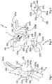
Figure 1 is an axonometric view of a support assembly for a loading apparatus, mounted on a tow hitch, in a release configuration; -
Figure 2 is an axonometric view of the tow hitch ofFigure 1 and an exploded view of the support assembly ofFigure 1 , with some parts cut away for clarity, showing a body and an activating lever of a fixing element; -
Figure 3 is an axonometric view of the fixing element ofFigure 2 ; -
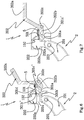
Figure 4 is a top view of the support assembly and of the tow hitch ofFigure 1 , in the release configuration; -
Figure 5 is a side view of the support assembly and of the tow hitch ofFigure 1 ; -
Figure 6 is a cross section through a plane VI-VI ofFigure 4 of the support assembly ofFigure 1 , in a release configuration; -
Figure 7 is the cross section view of the support assembly ofFigure 6 , in a fixing configuration. - With reference to the above-mentioned
Figures 1 to 7 , thenumeral 1 denotes a support assembly, made according to the invention, for a loading apparatus (not illustrated). Thesupport assembly 1 is configured to be removably mounted to atow hitch 2 of a vehicle (not illustrated). The loading apparatus may be, for example, a rear luggage rack for transporting additional items behind the car, a rear cycle carrier, or a ski rack. Without restricting the scope of the invention, the loading apparatus may be removably fixed to the support apparatus since, for example, it comprises a loading platform which can be removably fixed to the support assembly, or it may be made in a single body with the support assembly since, for example, the loading apparatus integrates the support assembly and the loading platform. - The
tow hitch 2 has a plane of symmetry S, extends along said plane of symmetry S, and comprises aneck 201 having a first end fixed (not illustrated), or removably fixable, to a rear part of the vehicle and a second end provided with asphere 202. - The
tow hitch 2 also comprises a pair ofpositioning pins 203, configured for correctly positioning thesupport assembly 1, which are arranged on theneck 201 at a predefined distance from thesphere 202 and project from theneck 202 transversally with respect to the plane of symmetry S. Thesupport assembly 1 comprises a body provided with ahooking part 101, which is provided with ahooking cavity 102 for receiving at least thesphere 202, and apositioning part 103, configured for cooperating with thepositioning pins 203. - The hooking
part 101 and thepositioning part 103 are made in a single body. Without restricting the scope of the invention, there could be, alternatively, separate parts, fixed to each other - The
positioning part 103 comprises a pair ofpositioning walls 104 between which theneck 201 is received at least partly. Eachpositioning wall 104 is positioned to make contact exclusively, when thesupport assembly 1 is mounted, with arear surface 203a of arespective pin 203. - It should be noted that in this description the relative terms mentioned below, that is, front and/or rear, upper and/or lower, top and/or bottom refer to a
support assembly 1, when thesupport assembly 1 is mounted on a vehicle. - The
support assembly 1 also comprises afixing device 3 for fixing thesupport assembly 1 against thetow hitch 2. - The
fixing device 3 comprises afixing element 301, which is movable between a fixing position (Figure 7 ) and a release position (Figure 6 ) and is configured for abutting abottom section 202a of thesphere 202 and ahead section 201a of theneck 201, contiguous to thebottom section 202a, when thesupport assembly 1 is mounted on thetow hitch 2 and thefixing element 301 is in the fixing position. - The term "
head section 201a of theneck 201" is used to mean a part of theneck 201, contiguous with thesphere 202, which has a transversal cross section with a diameter smaller than the remaining part. The term "bottom section 202a of thesphere 202" means, on the other hand, a part of thesphere 202 between an equatorial plane (not illustrated) of thesphere 202 and thehead section 201a of theneck 201. It should be noted that the equatorial plane of the sphere is a plane perpendicular to the plane of symmetry S. - Each
positioning wall 104 has arespective positioning edge 104a, which is arranged for abutting therear surface 203a of thepositioning pin 203 and is transversal, in particular perpendicular, with respect to the plane of symmetry S. - The
hooking cavity 102 has abottom wall 102a, which is closed, and an opening 102b located on the opposite side of thebottom wall 102a for the insertion of thesphere 202 in thehooking part 101. - The opening 102b is delimited by an
inserting edge 101a of the hooking part and by the pair ofpositioning edges 104a of thepositioning walls 104. Advantageously, according to the invention, by using asupport assembly 1, comprising the hookingpart 101 to receive thesphere 202 and thepositioning part 103 between thepositioning walls 104 of which is received at least partly theneck 201 of thetow hitch 2, a user can easily place thesphere 202 in thehooking cavity 102 through the opening 102b and move thepositioning edge 104a until making contact with thepositioning pin 103. - When the
positioning walls 104 are in contact with thepositioning pin 103, the positioning of thesupport assembly 1 on thetow hitch 2 has been performed correctly. - Also, by using the
fixing element 301 configured to make contact, in the fixing position, thebottom section 202a of thesphere 202 and the head section of 201a of theneck 201, thesupport assembly 1 is pushed against thesphere 202 and simultaneously also against theneck 201 and held firmly in position. - The
fixing element 301 can be moved in a fixing direction, between the release position and the fixing position, which is parallel, in particular coincides, with the plane of symmetry S. - The
fixing device 3 comprises an activatinglever 302 which has afirst end 302a with a handgrip which can be operated by a user and asecond end 302b equipped with an activating portion. - The activating
lever 302 is rotatable about a rotatingportion 302c positioned between thefirst end 302a and thesecond end 302b so that a user, by activating the activatinglever 302 in rotation about the rotatingportion 302c from a raised configuration to a lowered position, brings the activatingportion 302b initially to abut thefixing element 301 and subsequently to move thefixing element 301 between the release position and the fixing position in the fixing direction. - The
fixing device 3 also comprises a rod 303 (Figure 5 ) having two ends, each of which is fixed to arespective positioning wall 104 atrespective holes 105, the rotatingportion 302c being shaped like a hollow cylindrical portion arranged to house therod 303 so as to rotate about it. - Preferably, the
positioning walls 104 are parallel to one another and parallel to the plane of symmetry S. Therod 303 is, on the other hand, transversal, in particular perpendicular, to thepositioning walls 104. It follows, therefore, that the axis of rotation about which the activatinglever 302 rotates is perpendicular to the plane of symmetry S. - The
positioning part 103 comprises afixing seat 106, defined between thepositioning walls 104, which has aguide plane 107. - The
fixing element 301 is housed in thefixing seat 106 and is a convex solid which has 6 faces, in pairs opposite each other. Thefixing element 301 has abottom face 301a arranged resting on theguide plane 107 when thefixing element 301 is moved between the fixing position and the rele1ase position. Thebottom face 301a is flat. - The
fixing element 301 comprises a firstshaped face 301b, which is configured for abutting thebottom section 202a of thesphere 202 and thehead section 201a of theneck 201, and is provided with abottom portion 301b', having a complementary shape to thehead section 201a of theneck 201, and ahead portion 301b", having a complementary shape to thebottom section 202a of thesphere 202. - The
fixing element 301 also comprises a secondshaped face 301c, opposite the first shapedface 301b, which comprises abottom portion 301c' shaped as a flat inclined surface, which is configured for abutting the activatingportion 302b when thefixing element 301 is moved between the fixing position and the release position, and ahead portion 301 c", which is configured as a flat surface, transversal to the plane of symmetry S, for abutting the activatingportion 302b when the activatinglever 302 is in the lowered configuration. - The
fixing element 301 also has tworemaining faces 301e, opposite to each other, which are flat and which are in contact, when thesupport assembly 1 is mounted on thetow hitch 2, with thepositioning walls 104 so that thefixing element 301 slides on theguide plane 107 between thepositioning walls 104. - When the
support assembly 1 is mounted on thetow hitch 2, both thebottom portion 301b' of the first shapedface 301b and thebottom portion 301c' of the second shapedface 301c are positioned beneath therespective head portions 301b" and 301c". The activating portion of 302b is in fact shaped like a tapered cylinder, a side wall of which, when the activatinglever 302 is in the raised position, is positioned parallel and in contact with thebottom portion 301c' of the second shapedface 301c. In this way, during the rotation of the activatinglever 302 from the raised portion to the lowered portion, the side wall of the activatingportion 302b slides on thebottom portion 301c' until its relative end makes contact with thehead portion 301c'. In this way, the fixingelement 301 is pushed towards thetow hitch 2. - The fixing
element 301 has ahead face 301d opposite thebottom face 301a, which is positioned upwards when thesupport assembly 1 is mounted on thetow hitch 2. - The
support assembly 1 comprises in effect at least oneelastic element 4, a first end of which is fixed to one of thepositioning walls 104 and a second end of which is fixed to thehead face 301d of the fixingelement 301, for example to apin 401 protruding from thehead face 301d. - The
elastic element 4 is in a rest configuration when the fixingelement 301 is in the release position and is in an elongate configuration when the fixingelement 4 is in the fixing position. Theelastic element 4 therefore favours a movement of the fixingelement 301 from the fixing position to the release position and keeps the fixingelement 301 in contact with the activatingportion 302b, when the activatinglever 302 is activated by a user from the raised configuration to the lowered configuration. - The
support assembly 1 also comprises a furtherelastic element 5, a first end of which is fixed to theother positioning wall 104 and a second end of which is fixed to thehead face 301d, for example to afurther pin 501 which is also protrudes from thehead face 301d. - Only a few assembly steps are necessary, in use, for fixing the support assembly for 1 to the
tow hitch 2. - A first assembly step comprises, initially, the user positioning the
support assembly 1. - To do this, it is sufficient to position the
sphere 202 in thecavity 102 of the hookingpart 101 by inserting from above the hookingpart 101 on thesphere 202 and then positioning thepositioning walls 104 in contact with the positioning pins 103. - Thanks to the fact that the
positioning walls 104 make contact solely with arear surface 203a of thepositioning pin 203, the user can easily put in position thepositioning part 103, rotating it towards thetow hitch 2 until contact with therear surface 203a of thepositioning pin 103. In this way, the user can immediately perceive the correct positioning of thesupport assembly 1. - A second assembly step comprises the user fixing the
support assembly 1 to thetow hitch 2. In order to do this, it is merely necessary, whilst gripping thehandgrip 302a, to lower the activatinglever 302 rotating it about therod 303 so that the activatingposition 302b rotates upwards and raises it. Remaining in contact with thebottom portion 301c' of the second shapedsurface 302c during lifting, the activatingportion 302b pushes the fixingelement 303, which is resting on theguide plane 107, towards thetow hitch 2. When the activatinglever 302 is in the lowered position, the end of the activatingportion 302b is in contact and pushes thehead portion 301c" of the second shapedwall 301c towards thetow hitch 2. In this way, thebottom portion 301b' of the first shapedwall 301b makes contact with and pushes against thehead section 201a of theneck 201, and thehead portion 301b" of the first shapedwall 301b makes contact with and pushes against thebottom section 202a of thesphere 202. - Thanks to the fact that the first shaped
wall 301b has the shape of thebottom section 202a of thesphere 202 and thehead section 201a of theneck 201, the contact between the fixingelement 301 and thesphere 2 is optimum and the fixingelement 301 pushes effectively the support assembly against thetow hitch 2. - Thanks to the presence of a second shaped
wall 301c, opposite the first shapedwall 301b, on which the activatingportion 302b of the activatinglever 302 acts, the fixingelement 301 has reduced transversal dimensions. It follows that the fixingseat 106 may be also have reduced dimensions and a transversal dimension of the body formed by the hookingpart 101 and thepositioning part 103 may also be reduced.
Claims (11)
- A support assembly (1) configured for supporting a loading apparatus, wherein the support assembly (1) is also configured for removably hooking to a vehicle tow hitch (2), the tow hitch (2) having a plane of symmetry (S), extending along said plane of symmetry (S), and comprising:- a neck (201) having a first end fixed, or removably fixable, to a rear part of a vehicle and a second end provided with a sphere (202); a pair of positioning pins (203), configured for positioning the support assembly (1), which are arranged on the neck (201) at a predefined distance from the sphere (202) and project from the neck (201) transversally with respect to the plane of symmetry (S); wherein the support assembly (1) comprises:- a body provided with a hooking part (101), which is provided with a hooking cavity (102) for receiving at least the sphere (202), and a positioning part (103), configured for cooperating with the positioning pins (203), the positioning part (102) comprising a pair of positioning walls (104) between which the neck (201) is at least partially accommodated, each positioning wall (104) being arranged for abutting, when the support assembly (1) is mounted, exclusively a rear surface (203a) of a respective positioning pin (203);- a fixing device (3) comprising a fixing element (301), which is movable between a fixing position and a release position and is configured for abutting a bottom section (202a) of the sphere (202) and a head section (201a) of the neck (201), contiguous to said bottom section (202a), when the support assembly (1) is mounted and the fixing element (301) is in the fixing position.
- The support assembly according to claim 1, wherein each positioning wall (104) has a respective positioning edge (104a), arranged for abutting said rear surface (203a), which is transversal, in particular perpendicular, with respect to the plane of symmetry (S).
- The support assembly according to claim 2, wherein the hooking cavity (102) has a bottom wall (102a) that is closed and an opening (102b), arranged opposite to the bottom wall (102a), for inserting the sphere (202) in the hooking part (101); the opening being delimited by an inserting edge (101a) of the hooking part (101) and by the pair of positioning edges (104a) of the positioning walls (104).
- The support assembly according to one of the preceding claims, wherein the fixing device (3) further comprises an activating lever (302) which has a first end (302a) provided with a grip activatable by a user, a second end (302b) provided with an activating portion; wherein the activating lever (302) is rotatable about a rotating portion (302c) positioned between the first end (302a) and the second end (302b) so that a user, by activating the activating lever (302) in rotation about the rotating portion (302c) from a raised configuration to a lowered position, brings the activating portion (302b) initially to abut the fixing element (301) and subsequently to move the fixing element (301) between the release position and the fixing position.
- The support assembly according to claim 4, further comprising a rod (303) having two ends, each of which is fixed to a respective positioning wall (104), the rotating portion (302c) being configured as a hollow cylindrical portion arranged for housing the rod (303) so as to rotate about the rod.
- The support assembly according to claim 5, wherein the positioning walls (104) are parallel to one another and parallel to said plane of symmetry (S) and wherein said rod (303) is transversal, in particular perpendicular to said positioning walls (104).
- The support assembly according to one of the preceding claims, wherein the positioning part (102) comprises a fixing seating (105) defined between the positioning walls (104), which has a guide plane (107); the fixing element (301) being housed in the fixing seating (105) and having a bottom face (301a) arranged resting on the guide plane (107) when the fixing element (301) is moved between the fixing position and the release position.
- The support assembly according to one of the preceding claims, wherein the fixing element (301) comprises a first shaped face (301b), for abutting said bottom section (202a) of the sphere (202) and said head section (201a) of the neck (201), which comprises a bottom portion (301b'), having a complementary shape to the head section (201a) of the neck (201), and a head portion (301b"), having a complementary shape to the bottom section (202a) of the sphere (202).
- The support assembly according to claim 8, when dependent on one of claims from 4 to 6, wherein the fixing element (301) comprises a second shaped face (301c), opposite the first shaped face (301b), which comprises a bottom portion (301c') shaped as a flat inclined surface, which is configured for abutting the activating portion (302b) when the fixing element (301) is moved between the fixing position and the release position, and a head portion (301c"), which is configured as a flat surface for abutting the activating portion (302b) when the activating lever (302) is in the lowered configuration.
- The support assembly according to claim 7, or according to claim 8, or 9, when dependent on claim 7, wherein the fixing element (301) has a head face (301d) opposite said bottom face (301a) and the support assembly (1) comprises at least an elastic element (4), a first end of which is fixed to one of the positioning walls (104) and a second end of which is fixed to the head face (301d), the elastic element (4) being in a rest configuration when the fixing element (301) is in the release position and being in an elongate configuration when the fixing element (301) is in the fixing position for facilitating a displacing of the fixing element (301) from the fixing position to the release position, while maintaining the fixing element (301) in abutment with the activating portion (302b), when the activating lever (302) is activated by a user from the lowered configuration to the raised configuration.
- The support assembly according to claim 10 comprising a further elastic element (5), a first end of which is fixed to the other positioning wall (104) and a second end of which is fixed to the head face (301d), the elastic element (4) and the further elastic element (5) being symmetrically fixed to the head face (301d) on opposite sides with respect to the plane of symmetry (S).
Applications Claiming Priority (1)
| Application Number | Priority Date | Filing Date | Title |
|---|---|---|---|
| IT102017000111960A IT201700111960A1 (en) | 2017-10-05 | 2017-10-05 | Support assembly for a loading apparatus. |
Publications (2)
| Publication Number | Publication Date |
|---|---|
| EP3466766A1 EP3466766A1 (en) | 2019-04-10 |
| EP3466766B1 true EP3466766B1 (en) | 2021-04-14 |
Family
ID=61148367
Family Applications (1)
| Application Number | Title | Priority Date | Filing Date |
|---|---|---|---|
| EP18196972.6A Active EP3466766B1 (en) | 2017-10-05 | 2018-09-26 | A support assembly for a loading apparatus |
Country Status (2)
| Country | Link |
|---|---|
| EP (1) | EP3466766B1 (en) |
| IT (1) | IT201700111960A1 (en) |
Families Citing this family (1)
| Publication number | Priority date | Publication date | Assignee | Title |
|---|---|---|---|---|
| EP3772434B1 (en) * | 2019-08-05 | 2021-06-02 | Carman Enterprise Co., Ltd. | Rear load carrier |
Family Cites Families (3)
| Publication number | Priority date | Publication date | Assignee | Title |
|---|---|---|---|---|
| DE102013100780A1 (en) * | 2013-01-25 | 2014-07-31 | Scambia Holdings Cyprus Limited | Towing hitch and load carrier device for a trailer hitch |
| DE102014109134A1 (en) * | 2014-06-30 | 2015-12-31 | Scambia Holdings Cyprus Limited | Towing hitch and load carrier device for a trailer hitch |
| DE102013004484B4 (en) * | 2013-03-07 | 2025-07-17 | Westfalia-Automotive Gmbh | Load carrier coupling and load carrier |
-
2017
- 2017-10-05 IT IT102017000111960A patent/IT201700111960A1/en unknown
-
2018
- 2018-09-26 EP EP18196972.6A patent/EP3466766B1/en active Active
Non-Patent Citations (1)
| Title |
|---|
| None * |
Also Published As
| Publication number | Publication date |
|---|---|
| IT201700111960A1 (en) | 2019-04-05 |
| EP3466766A1 (en) | 2019-04-10 |
Similar Documents
| Publication | Publication Date | Title |
|---|---|---|
| US8496145B2 (en) | Vehicle rack for carrying a wheel | |
| US8979112B2 (en) | Adjustable hitch assembly | |
| US9199520B2 (en) | Adjustable hitch assembly | |
| US8132764B2 (en) | Quick-release adjustable mounting bracket | |
| US8231035B1 (en) | Hitch ball assembly holder | |
| US9533625B2 (en) | Bike rack attachment for vehicle | |
| CA2784589C (en) | Adaptive carrier insert bar assembly | |
| US9073396B2 (en) | Anti-rattle device for receiver hitches and accessories | |
| US10752066B2 (en) | Swing-away hitch adapter | |
| US20150076793A1 (en) | Anti-rattle device with hitch cover | |
| CA2160863A1 (en) | Article mounting assembly for a vehicle mounted carrier | |
| ES2773131T5 (en) | Trailer coupling and load support device for a trailer coupling | |
| US6863294B1 (en) | Easy alignment trailer hitch | |
| CN114829202B (en) | Support unit, method of mounting mounting portion thereon, and bicycle carrier | |
| EP3727901B1 (en) | Towbar with a hitch ball system | |
| CA2784461C (en) | Carrier insert bar assembly with securement pin | |
| EP3466766A1 (en) | A support assembly for a loading apparatus | |
| US20080217885A1 (en) | Trailer hitch alignment assembly kit | |
| US20080296330A1 (en) | Mountable storage arrangement | |
| JP3137975B2 (en) | Luggage carrier device | |
| CA3124549C (en) | Vehicle mounted bicycle carrier | |
| CZ291080B6 (en) | Device for storing and transporting motorcycles | |
| US20150307031A1 (en) | System for Transporting Child Stroller | |
| CA2624261C (en) | A multipurpose support for attachments mountable to the tow hitch of a vehicle | |
| US6851698B2 (en) | Coupling device |
Legal Events
| Date | Code | Title | Description |
|---|---|---|---|
| PUAI | Public reference made under article 153(3) epc to a published international application that has entered the european phase |
Free format text: ORIGINAL CODE: 0009012 |
|
| STAA | Information on the status of an ep patent application or granted ep patent |
Free format text: STATUS: THE APPLICATION HAS BEEN PUBLISHED |
|
| AK | Designated contracting states |
Kind code of ref document: A1 Designated state(s): AL AT BE BG CH CY CZ DE DK EE ES FI FR GB GR HR HU IE IS IT LI LT LU LV MC MK MT NL NO PL PT RO RS SE SI SK SM TR |
|
| AX | Request for extension of the european patent |
Extension state: BA ME |
|
| STAA | Information on the status of an ep patent application or granted ep patent |
Free format text: STATUS: REQUEST FOR EXAMINATION WAS MADE |
|
| 17P | Request for examination filed |
Effective date: 20191009 |
|
| RBV | Designated contracting states (corrected) |
Designated state(s): AL AT BE BG CH CY CZ DE DK EE ES FI FR GB GR HR HU IE IS IT LI LT LU LV MC MK MT NL NO PL PT RO RS SE SI SK SM TR |
|
| GRAP | Despatch of communication of intention to grant a patent |
Free format text: ORIGINAL CODE: EPIDOSNIGR1 |
|
| STAA | Information on the status of an ep patent application or granted ep patent |
Free format text: STATUS: GRANT OF PATENT IS INTENDED |
|
| INTG | Intention to grant announced |
Effective date: 20201203 |
|
| GRAS | Grant fee paid |
Free format text: ORIGINAL CODE: EPIDOSNIGR3 |
|
| GRAA | (expected) grant |
Free format text: ORIGINAL CODE: 0009210 |
|
| STAA | Information on the status of an ep patent application or granted ep patent |
Free format text: STATUS: THE PATENT HAS BEEN GRANTED |
|
| AK | Designated contracting states |
Kind code of ref document: B1 Designated state(s): AL AT BE BG CH CY CZ DE DK EE ES FI FR GB GR HR HU IE IS IT LI LT LU LV MC MK MT NL NO PL PT RO RS SE SI SK SM TR |
|
| REG | Reference to a national code |
Ref country code: GB Ref legal event code: FG4D |
|
| REG | Reference to a national code |
Ref country code: CH Ref legal event code: EP |
|
| REG | Reference to a national code |
Ref country code: DE Ref legal event code: R096 Ref document number: 602018015453 Country of ref document: DE |
|
| REG | Reference to a national code |
Ref country code: IE Ref legal event code: FG4D |
|
| REG | Reference to a national code |
Ref country code: AT Ref legal event code: REF Ref document number: 1382078 Country of ref document: AT Kind code of ref document: T Effective date: 20210515 |
|
| REG | Reference to a national code |
Ref country code: LT Ref legal event code: MG9D |
|
| REG | Reference to a national code |
Ref country code: AT Ref legal event code: MK05 Ref document number: 1382078 Country of ref document: AT Kind code of ref document: T Effective date: 20210414 |
|
| REG | Reference to a national code |
Ref country code: NL Ref legal event code: MP Effective date: 20210414 |
|
| PG25 | Lapsed in a contracting state [announced via postgrant information from national office to epo] |
Ref country code: HR Free format text: LAPSE BECAUSE OF FAILURE TO SUBMIT A TRANSLATION OF THE DESCRIPTION OR TO PAY THE FEE WITHIN THE PRESCRIBED TIME-LIMIT Effective date: 20210414 Ref country code: LT Free format text: LAPSE BECAUSE OF FAILURE TO SUBMIT A TRANSLATION OF THE DESCRIPTION OR TO PAY THE FEE WITHIN THE PRESCRIBED TIME-LIMIT Effective date: 20210414 Ref country code: FI Free format text: LAPSE BECAUSE OF FAILURE TO SUBMIT A TRANSLATION OF THE DESCRIPTION OR TO PAY THE FEE WITHIN THE PRESCRIBED TIME-LIMIT Effective date: 20210414 Ref country code: BG Free format text: LAPSE BECAUSE OF FAILURE TO SUBMIT A TRANSLATION OF THE DESCRIPTION OR TO PAY THE FEE WITHIN THE PRESCRIBED TIME-LIMIT Effective date: 20210714 Ref country code: AT Free format text: LAPSE BECAUSE OF FAILURE TO SUBMIT A TRANSLATION OF THE DESCRIPTION OR TO PAY THE FEE WITHIN THE PRESCRIBED TIME-LIMIT Effective date: 20210414 Ref country code: NL Free format text: LAPSE BECAUSE OF FAILURE TO SUBMIT A TRANSLATION OF THE DESCRIPTION OR TO PAY THE FEE WITHIN THE PRESCRIBED TIME-LIMIT Effective date: 20210414 |
|
| PG25 | Lapsed in a contracting state [announced via postgrant information from national office to epo] |
Ref country code: SE Free format text: LAPSE BECAUSE OF FAILURE TO SUBMIT A TRANSLATION OF THE DESCRIPTION OR TO PAY THE FEE WITHIN THE PRESCRIBED TIME-LIMIT Effective date: 20210414 Ref country code: RS Free format text: LAPSE BECAUSE OF FAILURE TO SUBMIT A TRANSLATION OF THE DESCRIPTION OR TO PAY THE FEE WITHIN THE PRESCRIBED TIME-LIMIT Effective date: 20210414 Ref country code: NO Free format text: LAPSE BECAUSE OF FAILURE TO SUBMIT A TRANSLATION OF THE DESCRIPTION OR TO PAY THE FEE WITHIN THE PRESCRIBED TIME-LIMIT Effective date: 20210714 Ref country code: LV Free format text: LAPSE BECAUSE OF FAILURE TO SUBMIT A TRANSLATION OF THE DESCRIPTION OR TO PAY THE FEE WITHIN THE PRESCRIBED TIME-LIMIT Effective date: 20210414 Ref country code: PL Free format text: LAPSE BECAUSE OF FAILURE TO SUBMIT A TRANSLATION OF THE DESCRIPTION OR TO PAY THE FEE WITHIN THE PRESCRIBED TIME-LIMIT Effective date: 20210414 Ref country code: PT Free format text: LAPSE BECAUSE OF FAILURE TO SUBMIT A TRANSLATION OF THE DESCRIPTION OR TO PAY THE FEE WITHIN THE PRESCRIBED TIME-LIMIT Effective date: 20210816 Ref country code: GR Free format text: LAPSE BECAUSE OF FAILURE TO SUBMIT A TRANSLATION OF THE DESCRIPTION OR TO PAY THE FEE WITHIN THE PRESCRIBED TIME-LIMIT Effective date: 20210715 Ref country code: IS Free format text: LAPSE BECAUSE OF FAILURE TO SUBMIT A TRANSLATION OF THE DESCRIPTION OR TO PAY THE FEE WITHIN THE PRESCRIBED TIME-LIMIT Effective date: 20210814 |
|
| REG | Reference to a national code |
Ref country code: DE Ref legal event code: R097 Ref document number: 602018015453 Country of ref document: DE |
|
| PG25 | Lapsed in a contracting state [announced via postgrant information from national office to epo] |
Ref country code: SK Free format text: LAPSE BECAUSE OF FAILURE TO SUBMIT A TRANSLATION OF THE DESCRIPTION OR TO PAY THE FEE WITHIN THE PRESCRIBED TIME-LIMIT Effective date: 20210414 Ref country code: SM Free format text: LAPSE BECAUSE OF FAILURE TO SUBMIT A TRANSLATION OF THE DESCRIPTION OR TO PAY THE FEE WITHIN THE PRESCRIBED TIME-LIMIT Effective date: 20210414 Ref country code: ES Free format text: LAPSE BECAUSE OF FAILURE TO SUBMIT A TRANSLATION OF THE DESCRIPTION OR TO PAY THE FEE WITHIN THE PRESCRIBED TIME-LIMIT Effective date: 20210414 Ref country code: EE Free format text: LAPSE BECAUSE OF FAILURE TO SUBMIT A TRANSLATION OF THE DESCRIPTION OR TO PAY THE FEE WITHIN THE PRESCRIBED TIME-LIMIT Effective date: 20210414 Ref country code: CZ Free format text: LAPSE BECAUSE OF FAILURE TO SUBMIT A TRANSLATION OF THE DESCRIPTION OR TO PAY THE FEE WITHIN THE PRESCRIBED TIME-LIMIT Effective date: 20210414 Ref country code: DK Free format text: LAPSE BECAUSE OF FAILURE TO SUBMIT A TRANSLATION OF THE DESCRIPTION OR TO PAY THE FEE WITHIN THE PRESCRIBED TIME-LIMIT Effective date: 20210414 Ref country code: RO Free format text: LAPSE BECAUSE OF FAILURE TO SUBMIT A TRANSLATION OF THE DESCRIPTION OR TO PAY THE FEE WITHIN THE PRESCRIBED TIME-LIMIT Effective date: 20210414 |
|
| PLBE | No opposition filed within time limit |
Free format text: ORIGINAL CODE: 0009261 |
|
| STAA | Information on the status of an ep patent application or granted ep patent |
Free format text: STATUS: NO OPPOSITION FILED WITHIN TIME LIMIT |
|
| 26N | No opposition filed |
Effective date: 20220117 |
|
| REG | Reference to a national code |
Ref country code: CH Ref legal event code: PL |
|
| REG | Reference to a national code |
Ref country code: BE Ref legal event code: MM Effective date: 20210930 |
|
| PG25 | Lapsed in a contracting state [announced via postgrant information from national office to epo] |
Ref country code: IS Free format text: LAPSE BECAUSE OF FAILURE TO SUBMIT A TRANSLATION OF THE DESCRIPTION OR TO PAY THE FEE WITHIN THE PRESCRIBED TIME-LIMIT Effective date: 20210814 Ref country code: MC Free format text: LAPSE BECAUSE OF FAILURE TO SUBMIT A TRANSLATION OF THE DESCRIPTION OR TO PAY THE FEE WITHIN THE PRESCRIBED TIME-LIMIT Effective date: 20210414 Ref country code: AL Free format text: LAPSE BECAUSE OF FAILURE TO SUBMIT A TRANSLATION OF THE DESCRIPTION OR TO PAY THE FEE WITHIN THE PRESCRIBED TIME-LIMIT Effective date: 20210414 |
|
| PG25 | Lapsed in a contracting state [announced via postgrant information from national office to epo] |
Ref country code: LU Free format text: LAPSE BECAUSE OF NON-PAYMENT OF DUE FEES Effective date: 20210926 Ref country code: IE Free format text: LAPSE BECAUSE OF NON-PAYMENT OF DUE FEES Effective date: 20210926 Ref country code: BE Free format text: LAPSE BECAUSE OF NON-PAYMENT OF DUE FEES Effective date: 20210930 |
|
| PG25 | Lapsed in a contracting state [announced via postgrant information from national office to epo] |
Ref country code: LI Free format text: LAPSE BECAUSE OF NON-PAYMENT OF DUE FEES Effective date: 20210930 Ref country code: CH Free format text: LAPSE BECAUSE OF NON-PAYMENT OF DUE FEES Effective date: 20210930 |
|
| P01 | Opt-out of the competence of the unified patent court (upc) registered |
Effective date: 20230523 |
|
| PG25 | Lapsed in a contracting state [announced via postgrant information from national office to epo] |
Ref country code: CY Free format text: LAPSE BECAUSE OF FAILURE TO SUBMIT A TRANSLATION OF THE DESCRIPTION OR TO PAY THE FEE WITHIN THE PRESCRIBED TIME-LIMIT Effective date: 20210414 |
|
| PG25 | Lapsed in a contracting state [announced via postgrant information from national office to epo] |
Ref country code: HU Free format text: LAPSE BECAUSE OF FAILURE TO SUBMIT A TRANSLATION OF THE DESCRIPTION OR TO PAY THE FEE WITHIN THE PRESCRIBED TIME-LIMIT; INVALID AB INITIO Effective date: 20180926 |
|
| PGFP | Annual fee paid to national office [announced via postgrant information from national office to epo] |
Ref country code: GB Payment date: 20230926 Year of fee payment: 6 |
|
| PGFP | Annual fee paid to national office [announced via postgrant information from national office to epo] |
Ref country code: FR Payment date: 20230926 Year of fee payment: 6 Ref country code: DE Payment date: 20230928 Year of fee payment: 6 |
|
| PGFP | Annual fee paid to national office [announced via postgrant information from national office to epo] |
Ref country code: IT Payment date: 20230927 Year of fee payment: 6 |
|
| PG25 | Lapsed in a contracting state [announced via postgrant information from national office to epo] |
Ref country code: MK Free format text: LAPSE BECAUSE OF FAILURE TO SUBMIT A TRANSLATION OF THE DESCRIPTION OR TO PAY THE FEE WITHIN THE PRESCRIBED TIME-LIMIT Effective date: 20210414 |
|
| PG25 | Lapsed in a contracting state [announced via postgrant information from national office to epo] |
Ref country code: TR Free format text: LAPSE BECAUSE OF FAILURE TO SUBMIT A TRANSLATION OF THE DESCRIPTION OR TO PAY THE FEE WITHIN THE PRESCRIBED TIME-LIMIT Effective date: 20210414 |
|
| PG25 | Lapsed in a contracting state [announced via postgrant information from national office to epo] |
Ref country code: MT Free format text: LAPSE BECAUSE OF FAILURE TO SUBMIT A TRANSLATION OF THE DESCRIPTION OR TO PAY THE FEE WITHIN THE PRESCRIBED TIME-LIMIT Effective date: 20210414 |
|
| REG | Reference to a national code |
Ref country code: DE Ref legal event code: R119 Ref document number: 602018015453 Country of ref document: DE |
|
| GBPC | Gb: european patent ceased through non-payment of renewal fee |
Effective date: 20240926 |
|
| PG25 | Lapsed in a contracting state [announced via postgrant information from national office to epo] |
Ref country code: DE Free format text: LAPSE BECAUSE OF NON-PAYMENT OF DUE FEES Effective date: 20250401 |
|
| PG25 | Lapsed in a contracting state [announced via postgrant information from national office to epo] |
Ref country code: GB Free format text: LAPSE BECAUSE OF NON-PAYMENT OF DUE FEES Effective date: 20240926 |
|
| PG25 | Lapsed in a contracting state [announced via postgrant information from national office to epo] |
Ref country code: IT Free format text: LAPSE BECAUSE OF NON-PAYMENT OF DUE FEES Effective date: 20240926 |
|
| PG25 | Lapsed in a contracting state [announced via postgrant information from national office to epo] |
Ref country code: FR Free format text: LAPSE BECAUSE OF NON-PAYMENT OF DUE FEES Effective date: 20240930 |