EP3466602A1 - Method for forming article, method for forming turbine bucket, and turbine bucket - Google Patents
Method for forming article, method for forming turbine bucket, and turbine bucket Download PDFInfo
- Publication number
- EP3466602A1 EP3466602A1 EP18192703.9A EP18192703A EP3466602A1 EP 3466602 A1 EP3466602 A1 EP 3466602A1 EP 18192703 A EP18192703 A EP 18192703A EP 3466602 A1 EP3466602 A1 EP 3466602A1
- Authority
- EP
- European Patent Office
- Prior art keywords
- cladding layer
- cobalt
- weld
- nickel
- metal alloy
- Prior art date
- Legal status (The legal status is an assumption and is not a legal conclusion. Google has not performed a legal analysis and makes no representation as to the accuracy of the status listed.)
- Granted
Links
Images



Classifications
-
- B—PERFORMING OPERATIONS; TRANSPORTING
- B23—MACHINE TOOLS; METAL-WORKING NOT OTHERWISE PROVIDED FOR
- B23K—SOLDERING OR UNSOLDERING; WELDING; CLADDING OR PLATING BY SOLDERING OR WELDING; CUTTING BY APPLYING HEAT LOCALLY, e.g. FLAME CUTTING; WORKING BY LASER BEAM
- B23K26/00—Working by laser beam, e.g. welding, cutting or boring
- B23K26/20—Bonding
- B23K26/21—Bonding by welding
- B23K26/24—Seam welding
- B23K26/30—Seam welding of three-dimensional [3D] seams
-
- C—CHEMISTRY; METALLURGY
- C23—COATING METALLIC MATERIAL; COATING MATERIAL WITH METALLIC MATERIAL; CHEMICAL SURFACE TREATMENT; DIFFUSION TREATMENT OF METALLIC MATERIAL; COATING BY VACUUM EVAPORATION, BY SPUTTERING, BY ION IMPLANTATION OR BY CHEMICAL VAPOUR DEPOSITION, IN GENERAL; INHIBITING CORROSION OF METALLIC MATERIAL OR INCRUSTATION IN GENERAL
- C23C—COATING METALLIC MATERIAL; COATING MATERIAL WITH METALLIC MATERIAL; SURFACE TREATMENT OF METALLIC MATERIAL BY DIFFUSION INTO THE SURFACE, BY CHEMICAL CONVERSION OR SUBSTITUTION; COATING BY VACUUM EVAPORATION, BY SPUTTERING, BY ION IMPLANTATION OR BY CHEMICAL VAPOUR DEPOSITION, IN GENERAL
- C23C24/00—Coating starting from inorganic powder
- C23C24/08—Coating starting from inorganic powder by application of heat or pressure and heat
- C23C24/10—Coating starting from inorganic powder by application of heat or pressure and heat with intermediate formation of a liquid phase in the layer
- C23C24/103—Coating with metallic material, i.e. metals or metal alloys, optionally comprising hard particles, e.g. oxides, carbides or nitrides
- C23C24/106—Coating with metal alloys or metal elements only
-
- B—PERFORMING OPERATIONS; TRANSPORTING
- B23—MACHINE TOOLS; METAL-WORKING NOT OTHERWISE PROVIDED FOR
- B23K—SOLDERING OR UNSOLDERING; WELDING; CLADDING OR PLATING BY SOLDERING OR WELDING; CUTTING BY APPLYING HEAT LOCALLY, e.g. FLAME CUTTING; WORKING BY LASER BEAM
- B23K26/00—Working by laser beam, e.g. welding, cutting or boring
- B23K26/0006—Working by laser beam, e.g. welding, cutting or boring taking account of the properties of the material involved
-
- B—PERFORMING OPERATIONS; TRANSPORTING
- B23—MACHINE TOOLS; METAL-WORKING NOT OTHERWISE PROVIDED FOR
- B23K—SOLDERING OR UNSOLDERING; WELDING; CLADDING OR PLATING BY SOLDERING OR WELDING; CUTTING BY APPLYING HEAT LOCALLY, e.g. FLAME CUTTING; WORKING BY LASER BEAM
- B23K26/00—Working by laser beam, e.g. welding, cutting or boring
- B23K26/08—Devices involving relative movement between laser beam and workpiece
-
- B—PERFORMING OPERATIONS; TRANSPORTING
- B23—MACHINE TOOLS; METAL-WORKING NOT OTHERWISE PROVIDED FOR
- B23K—SOLDERING OR UNSOLDERING; WELDING; CLADDING OR PLATING BY SOLDERING OR WELDING; CUTTING BY APPLYING HEAT LOCALLY, e.g. FLAME CUTTING; WORKING BY LASER BEAM
- B23K26/00—Working by laser beam, e.g. welding, cutting or boring
- B23K26/14—Working by laser beam, e.g. welding, cutting or boring using a fluid stream, e.g. a jet of gas, in conjunction with the laser beam; Nozzles therefor
- B23K26/144—Working by laser beam, e.g. welding, cutting or boring using a fluid stream, e.g. a jet of gas, in conjunction with the laser beam; Nozzles therefor the fluid stream containing particles, e.g. powder
-
- B—PERFORMING OPERATIONS; TRANSPORTING
- B23—MACHINE TOOLS; METAL-WORKING NOT OTHERWISE PROVIDED FOR
- B23K—SOLDERING OR UNSOLDERING; WELDING; CLADDING OR PLATING BY SOLDERING OR WELDING; CUTTING BY APPLYING HEAT LOCALLY, e.g. FLAME CUTTING; WORKING BY LASER BEAM
- B23K26/00—Working by laser beam, e.g. welding, cutting or boring
- B23K26/34—Laser welding for purposes other than joining
-
- B—PERFORMING OPERATIONS; TRANSPORTING
- B23—MACHINE TOOLS; METAL-WORKING NOT OTHERWISE PROVIDED FOR
- B23K—SOLDERING OR UNSOLDERING; WELDING; CLADDING OR PLATING BY SOLDERING OR WELDING; CUTTING BY APPLYING HEAT LOCALLY, e.g. FLAME CUTTING; WORKING BY LASER BEAM
- B23K26/00—Working by laser beam, e.g. welding, cutting or boring
- B23K26/34—Laser welding for purposes other than joining
- B23K26/342—Build-up welding
-
- B—PERFORMING OPERATIONS; TRANSPORTING
- B23—MACHINE TOOLS; METAL-WORKING NOT OTHERWISE PROVIDED FOR
- B23K—SOLDERING OR UNSOLDERING; WELDING; CLADDING OR PLATING BY SOLDERING OR WELDING; CUTTING BY APPLYING HEAT LOCALLY, e.g. FLAME CUTTING; WORKING BY LASER BEAM
- B23K35/00—Rods, electrodes, materials, or media, for use in soldering, welding, or cutting
- B23K35/02—Rods, electrodes, materials, or media, for use in soldering, welding, or cutting characterised by mechanical features, e.g. shape
- B23K35/0255—Rods, electrodes, materials, or media, for use in soldering, welding, or cutting characterised by mechanical features, e.g. shape for use in welding
-
- B—PERFORMING OPERATIONS; TRANSPORTING
- B23—MACHINE TOOLS; METAL-WORKING NOT OTHERWISE PROVIDED FOR
- B23K—SOLDERING OR UNSOLDERING; WELDING; CLADDING OR PLATING BY SOLDERING OR WELDING; CUTTING BY APPLYING HEAT LOCALLY, e.g. FLAME CUTTING; WORKING BY LASER BEAM
- B23K35/00—Rods, electrodes, materials, or media, for use in soldering, welding, or cutting
- B23K35/22—Rods, electrodes, materials, or media, for use in soldering, welding, or cutting characterised by the composition or nature of the material
- B23K35/24—Selection of soldering or welding materials proper
- B23K35/30—Selection of soldering or welding materials proper with the principal constituent melting at less than 1550°C
- B23K35/3033—Ni as the principal constituent
- B23K35/304—Ni as the principal constituent with Cr as the next major constituent
-
- C—CHEMISTRY; METALLURGY
- C22—METALLURGY; FERROUS OR NON-FERROUS ALLOYS; TREATMENT OF ALLOYS OR NON-FERROUS METALS
- C22C—ALLOYS
- C22C19/00—Alloys based on nickel or cobalt
- C22C19/03—Alloys based on nickel or cobalt based on nickel
- C22C19/05—Alloys based on nickel or cobalt based on nickel with chromium
- C22C19/051—Alloys based on nickel or cobalt based on nickel with chromium and Mo or W
- C22C19/055—Alloys based on nickel or cobalt based on nickel with chromium and Mo or W with the maximum Cr content being at least 20% but less than 30%
-
- C—CHEMISTRY; METALLURGY
- C22—METALLURGY; FERROUS OR NON-FERROUS ALLOYS; TREATMENT OF ALLOYS OR NON-FERROUS METALS
- C22C—ALLOYS
- C22C19/00—Alloys based on nickel or cobalt
- C22C19/03—Alloys based on nickel or cobalt based on nickel
- C22C19/05—Alloys based on nickel or cobalt based on nickel with chromium
- C22C19/051—Alloys based on nickel or cobalt based on nickel with chromium and Mo or W
- C22C19/056—Alloys based on nickel or cobalt based on nickel with chromium and Mo or W with the maximum Cr content being at least 10% but less than 20%
-
- C—CHEMISTRY; METALLURGY
- C22—METALLURGY; FERROUS OR NON-FERROUS ALLOYS; TREATMENT OF ALLOYS OR NON-FERROUS METALS
- C22C—ALLOYS
- C22C19/00—Alloys based on nickel or cobalt
- C22C19/03—Alloys based on nickel or cobalt based on nickel
- C22C19/05—Alloys based on nickel or cobalt based on nickel with chromium
- C22C19/058—Alloys based on nickel or cobalt based on nickel with chromium without Mo and W
-
- C—CHEMISTRY; METALLURGY
- C22—METALLURGY; FERROUS OR NON-FERROUS ALLOYS; TREATMENT OF ALLOYS OR NON-FERROUS METALS
- C22C—ALLOYS
- C22C19/00—Alloys based on nickel or cobalt
- C22C19/07—Alloys based on nickel or cobalt based on cobalt
-
- F—MECHANICAL ENGINEERING; LIGHTING; HEATING; WEAPONS; BLASTING
- F01—MACHINES OR ENGINES IN GENERAL; ENGINE PLANTS IN GENERAL; STEAM ENGINES
- F01D—NON-POSITIVE DISPLACEMENT MACHINES OR ENGINES, e.g. STEAM TURBINES
- F01D5/00—Blades; Blade-carrying members; Heating, heat-insulating, cooling or antivibration means on the blades or the members
- F01D5/12—Blades
- F01D5/14—Form or construction
- F01D5/147—Construction, i.e. structural features, e.g. of weight-saving hollow blades
-
- F—MECHANICAL ENGINEERING; LIGHTING; HEATING; WEAPONS; BLASTING
- F01—MACHINES OR ENGINES IN GENERAL; ENGINE PLANTS IN GENERAL; STEAM ENGINES
- F01D—NON-POSITIVE DISPLACEMENT MACHINES OR ENGINES, e.g. STEAM TURBINES
- F01D5/00—Blades; Blade-carrying members; Heating, heat-insulating, cooling or antivibration means on the blades or the members
- F01D5/12—Blades
- F01D5/14—Form or construction
- F01D5/20—Specially-shaped blade tips to seal space between tips and stator
-
- F—MECHANICAL ENGINEERING; LIGHTING; HEATING; WEAPONS; BLASTING
- F01—MACHINES OR ENGINES IN GENERAL; ENGINE PLANTS IN GENERAL; STEAM ENGINES
- F01D—NON-POSITIVE DISPLACEMENT MACHINES OR ENGINES, e.g. STEAM TURBINES
- F01D5/00—Blades; Blade-carrying members; Heating, heat-insulating, cooling or antivibration means on the blades or the members
- F01D5/12—Blades
- F01D5/28—Selecting particular materials; Particular measures relating thereto; Measures against erosion or corrosion
-
- F—MECHANICAL ENGINEERING; LIGHTING; HEATING; WEAPONS; BLASTING
- F01—MACHINES OR ENGINES IN GENERAL; ENGINE PLANTS IN GENERAL; STEAM ENGINES
- F01D—NON-POSITIVE DISPLACEMENT MACHINES OR ENGINES, e.g. STEAM TURBINES
- F01D5/00—Blades; Blade-carrying members; Heating, heat-insulating, cooling or antivibration means on the blades or the members
- F01D5/12—Blades
- F01D5/28—Selecting particular materials; Particular measures relating thereto; Measures against erosion or corrosion
- F01D5/288—Protective coatings for blades
-
- B—PERFORMING OPERATIONS; TRANSPORTING
- B23—MACHINE TOOLS; METAL-WORKING NOT OTHERWISE PROVIDED FOR
- B23K—SOLDERING OR UNSOLDERING; WELDING; CLADDING OR PLATING BY SOLDERING OR WELDING; CUTTING BY APPLYING HEAT LOCALLY, e.g. FLAME CUTTING; WORKING BY LASER BEAM
- B23K2101/00—Articles made by soldering, welding or cutting
- B23K2101/001—Turbines
-
- B—PERFORMING OPERATIONS; TRANSPORTING
- B23—MACHINE TOOLS; METAL-WORKING NOT OTHERWISE PROVIDED FOR
- B23K—SOLDERING OR UNSOLDERING; WELDING; CLADDING OR PLATING BY SOLDERING OR WELDING; CUTTING BY APPLYING HEAT LOCALLY, e.g. FLAME CUTTING; WORKING BY LASER BEAM
- B23K35/00—Rods, electrodes, materials, or media, for use in soldering, welding, or cutting
- B23K35/02—Rods, electrodes, materials, or media, for use in soldering, welding, or cutting characterised by mechanical features, e.g. shape
- B23K35/0222—Rods, electrodes, materials, or media, for use in soldering, welding, or cutting characterised by mechanical features, e.g. shape for use in soldering or brazing
- B23K35/0244—Powders, particles or spheres; Preforms made therefrom
-
- F—MECHANICAL ENGINEERING; LIGHTING; HEATING; WEAPONS; BLASTING
- F05—INDEXING SCHEMES RELATING TO ENGINES OR PUMPS IN VARIOUS SUBCLASSES OF CLASSES F01-F04
- F05D—INDEXING SCHEME FOR ASPECTS RELATING TO NON-POSITIVE-DISPLACEMENT MACHINES OR ENGINES, GAS-TURBINES OR JET-PROPULSION PLANTS
- F05D2220/00—Application
- F05D2220/30—Application in turbines
- F05D2220/32—Application in turbines in gas turbines
-
- F—MECHANICAL ENGINEERING; LIGHTING; HEATING; WEAPONS; BLASTING
- F05—INDEXING SCHEMES RELATING TO ENGINES OR PUMPS IN VARIOUS SUBCLASSES OF CLASSES F01-F04
- F05D—INDEXING SCHEME FOR ASPECTS RELATING TO NON-POSITIVE-DISPLACEMENT MACHINES OR ENGINES, GAS-TURBINES OR JET-PROPULSION PLANTS
- F05D2230/00—Manufacture
- F05D2230/20—Manufacture essentially without removing material
- F05D2230/23—Manufacture essentially without removing material by permanently joining parts together
- F05D2230/232—Manufacture essentially without removing material by permanently joining parts together by welding
- F05D2230/234—Laser welding
-
- F—MECHANICAL ENGINEERING; LIGHTING; HEATING; WEAPONS; BLASTING
- F05—INDEXING SCHEMES RELATING TO ENGINES OR PUMPS IN VARIOUS SUBCLASSES OF CLASSES F01-F04
- F05D—INDEXING SCHEME FOR ASPECTS RELATING TO NON-POSITIVE-DISPLACEMENT MACHINES OR ENGINES, GAS-TURBINES OR JET-PROPULSION PLANTS
- F05D2240/00—Components
- F05D2240/20—Rotors
- F05D2240/30—Characteristics of rotor blades, i.e. of any element transforming dynamic fluid energy to or from rotational energy and being attached to a rotor
- F05D2240/307—Characteristics of rotor blades, i.e. of any element transforming dynamic fluid energy to or from rotational energy and being attached to a rotor related to the tip of a rotor blade
-
- F—MECHANICAL ENGINEERING; LIGHTING; HEATING; WEAPONS; BLASTING
- F05—INDEXING SCHEMES RELATING TO ENGINES OR PUMPS IN VARIOUS SUBCLASSES OF CLASSES F01-F04
- F05D—INDEXING SCHEME FOR ASPECTS RELATING TO NON-POSITIVE-DISPLACEMENT MACHINES OR ENGINES, GAS-TURBINES OR JET-PROPULSION PLANTS
- F05D2300/00—Materials; Properties thereof
- F05D2300/10—Metals, alloys or intermetallic compounds
- F05D2300/17—Alloys
Definitions
- the present invention is directed to methods for forming articles, methods for forming turbine buckets, and turbine buckets. More particularly, the present invention is directed to methods for forming articles and methods for forming turbine buckets including laser welding a powder of a hard-to-weld alloy to form a cladding layer, and turbine buckets including a squealer tip having a cladding layer of a hard-to-weld alloy.
- HMW alloys due to their gamma prime and various geometric constraints, are susceptible to gamma prime strain aging, liquation and hot cracking. These materials are also difficult to join when the gamma prime phase is present in volume fractions greater than about 30%, which may occur when aluminum or titanium content exceeds about 3%.
- an "HTW alloy” is an alloy which exhibits liquation, hot and strain-age cracking, and which is therefore impractical to weld in a repeatable manner without significant rework.
- HTW alloys may be incorporated into various components of gas turbine engines such as airfoils, blades (buckets), nozzles (vanes), shrouds, combustors, rotating turbine components, wheels, seals, and other hot gas path components. Incorporation of these HTW alloys may be desirable due to often superior operational properties, particularly for certain components subjected to the most extreme conditions and stresses. Additionally, certain HTW alloys may impart advantageous oxidation and corrosion properties when applied as cladding layers to other alloys, such as cladding layers applied to turbine buckets to form squealer tips.
- HTW alloys as cladding layer presents significant challenges, particularly because certain HTW alloys tend to form undesirable cracks when a weld bead of such an alloy is applied to a surface in contact with a previously applied weld bead of the alloy.
- Such challenges inhibit the formation of continuous cladding layers by standard techniques, such as build-up by concentric weld beads, and further inhibit the formation of layers of the HTW alloys more than a single weld bead in thickness.
- a method for forming an article includes laser welding a powder of a metal alloy to a surface of a substrate along a weld path, forming a weld bead of the metal alloy having a weld bead width and a weld bead height.
- the weld path is propagated along a weld direction, forming a cladding layer of the metal alloy disposed on the surface having a cladding layer thickness.
- the metal alloy is an HTW alloy.
- the laser welding includes a laser energy density of at least about 11 kJ/cm 2 .
- Laser welding the powder of the metal alloy to the surface of the substrate along the weld path includes a welding speed between about 5 ipm to about 20 ipm.
- the weld path oscillates essentially nonparallel relative to a reference line, establishing a cladding width wider than the weld bead width.
- the weld bead contacts itself along each oscillation such that the cladding layer is continuous.
- the cladding layer is essentially free of cracks.
- a method for forming a turbine bucket including a squealer tip includes laser welding a powder of a metal alloy to a surface of a substrate along a weld path, forming a weld bead of the metal alloy having a weld bead width and a weld bead height.
- the weld path is propagated along a weld direction, forming a cladding layer of the metal alloy disposed on the surface having a cladding layer thickness.
- the metal alloy consists essentially of, by weight: about 15% to about 17% chromium; about 4% to about 5% aluminum; about 2% to about 4% iron; about 0.002% to about 0.04% yttrium; up to about 0.5% manganese; up to about 0.2% silicon; up to about 0.1% zirconium; up to about 0.05% carbon; up to about 0.5% tungsten; up to about 2% cobalt; up to about 0.15% niobium; up to about 0.5% titanium; up to about 0.5% molybdenum; up to about 0.01% boron; and a balance of nickel.
- the surface of the substrate includes a surface layer of a surface material selected from the group consisting of: an alloy composition including, by weight: about 21% to about 23% chromium; about 13% to about 15% tungsten; about 1% to about 3% molybdenum; about 0.25% to about 0.75% manganese; about 0.2% to about 0.6% silicon; about 0.1% to about 0.5% aluminum; about 0.05% to about 0.15% carbon; about 0.01% to about 0.03% lanthanum; up to about 3% iron; up to about 5% cobalt; up to about 0.5% niobium; up to about 0.1% titanium; up to about 0.015% boron; and a balance of nickel; an alloy composition including, by weight: about 20% to about 23% chromium; about 8% to about 10% molybdenum; about 3.15% to about 4.15% niobium and tantalum; up to about 5% iron; up to about 0.1% carbon; up to about 0.5% manganese; up to about 0.5% silicon; up
- the laser welding includes a laser energy density of between about 11.5 kJ/cm 2 to about 20.3 kJ/cm 2 .
- Laser welding the powder of the metal alloy to the surface of the substrate along the weld path includes a welding speed between about 5 ipm to about 20 ipm.
- the powder is applied at a flow rate of between about 4.8 g/min to about 5.2 g/min.
- the weld path oscillates essentially nonparallel relative to a reference line, establishing a cladding width wider than the weld bead width.
- the weld bead contacts itself along each oscillation such that the cladding layer is continuous.
- the cladding layer is essentially free of cracks.
- the cladding layer forms at least a portion of the squealer tip.
- the weld path commences at a trailing edge of the turbine bucket, proceeds across a trailing edge width of the trailing edge, and then proceeds around a periphery of the turbine bucket along one of a suction side and a pressure side, through a leading edge, and back along the other of the suction side and the pressure side until returning to the trailing edge.
- the cladding layer thickness is at least about 0.2 inches. Forming the cladding layer is free of gas tungsten arc welding.
- a turbine bucket in another exemplary embodiment, includes a squealer tip, and the squealer tip includes a cladding layer consisting essentially of, by weight: about 15% to about 17% chromium; about 4% to about 5% aluminum; about 2% to about 4% iron; about 0.002% to about 0.04% yttrium; up to about 0.5% manganese; up to about 0.2% silicon; up to about 0.1% zirconium; up to about 0.05% carbon; up to about 0.5% tungsten; up to about 2% cobalt; up to about 0.15% niobium; up to about 0.5% titanium; up to about 0.5% molybdenum; up to about 0.01% boron; and a balance of nickel.
- the cladding layer is essentially free of cracks, and the cladding layer includes a cladding layer thickness of at least about 0.2 inches.
- Embodiments of the present disclosure in comparison to articles and methods not utilizing one or more features disclosed herein, decrease costs, increase process control, increase process efficiency, increase process speed, increase repeatability, increase cladding layer thickness ranges, decrease squealer tip composition complexity, decrease or eliminate crack occurrence, or combinations thereof.
- GTD 111 refers to an alloy including a composition, by weight, of about 13.5% to about 14.5% chromium, about 9% to about 10% cobalt, about 3.3% to about 4.3% tungsten, about 4.4% to about 5.4% titanium, about 2.5% to about 3.5% aluminum, about 0.05% to about 0.15% iron, about 2.3% to about 3.3% tantalum, about 1.1% to about 2.1% molybdenum, about 0.05% to about 0.15% carbon, and a balance of nickel.
- GTD 111 is available from General Electric Company, 1 River Road, Schenectady, NY 12345.
- GTD 222 refers to an alloy including a composition, by weight, of about 22.5% to about 24.5% chromium, about 18% to about 20% cobalt, about 1.5% to about 2.5% tungsten, about 0.3% to about 1.3% niobium, about 1.8% to about 2.8% titanium, about 0.7% to about 1.7% aluminum, about 0.5% to about 1.5% tantalum, about 0.15% to about 0.35% silicon, about 0.05% to about 0.15% manganese, and a balance of nickel.
- GTD 222 is available from General Electric Company, 1 River Road, Schenectady, NY 12345.
- HAYNES 214" refers to an alloy including a composition, by weight, of about 15% to about 17% chromium, about 4% to about 5% aluminum, about 2% to about 4% iron, about 0.002% to about 0.04% yttrium, up to about 0.5% manganese, up to about 0.2% silicon, up to about 0.1% zirconium, up to about 0.05% carbon, up to about 0.5% tungsten, up to about 2% cobalt, up to about 0.15% niobium, up to about 0.5% titanium, up to about 0.5% molybdenum, up to about 0.01% boron, and a balance of nickel.
- HAYNES 214 is available from H.C. Starck, 45 Industrial Place, Newton, Massachusetts 02461-1951.
- HAYNES 230 refers to an alloy including a composition, by weight, of about 21% to about 23% chromium, about 13% to about 15% tungsten, about 1% to about 3% molybdenum, about 0.25% to about 0.75% manganese, about 0.2% to about 0.6% silicon, about 0.1% to about 0.5% aluminum, about 0.05% to about 0.15% carbon, about 0.01% to about 0.03% lanthanum, up to about 3% iron, up to about 5% cobalt, up to about 0.5% niobium, up to about 0.1% titanium, up to about 0.015% boron, and a balance of nickel. HAYNES 230 is available from Haynes International, 1020 W. Park Avenue, Kokomo, Indiana, 46904-9013.
- INCONEL 625 is available from Special Metals Corporation, 3200 Riverside Drive, Huntington, West Virginia 25720.
- INCONEL 718 refers to an alloy including a composition, by weight, of about 17% to about 21% chromium, about 50% to about 55% nickel and cobalt, about 4.75% to about 5.5% niobium and tantalum, about 2.8% to about 3.3% molybdenum, about 0.65% to about 1.15% titanium, about 0.2% to about 0.8% aluminum, up to about 1% cobalt, up to about 0.08% carbon, up to about 0.35% manganese, up to about 0.35% silicon, up to about 0.015% phosphorous, up to about 0.015% sulfur, up to about 0.006% boron, up to about 0.3% copper, and a balance of iron. INCONEL 718 is available from Special Metals Corporation, 3200 Riverside Drive, Huntington, West Virginia 25720.
- MAR-M-247 refers to an alloy including a composition, by weight, of about 5.4% to about 5.7% aluminum, about 8% to about 8.5% chromium, about 9% to about 9.5% cobalt, about 9.3% to about 9.7% tungsten, about 0.05% to about 0.15% manganese, about 0.15% to about 0.35% silicon, about 0.06% to about 0.09% carbon, and a balance of nickel.
- MAR-M-247 is available from MetalTek International, 905 E. St. Paul Avenue, Waukesha, Wisconsin 53188.
- MERL 72 refers to an alloy including a composition, by weight, of about 14% to about 16% nickel, about 19% to about 21% chromium, about 8% to about 10% tungsten, about 4.0% to about 4.8% aluminum, about 0.1% to about 0.3% titanium, about 2% to about 4% tantalum, about 0.25% to about 0.45% carbon, about 0.5% to about 1.5% hafnium, about 0.35% to about 0.55% yttrium, and a balance of cobalt. MERL 72 is available from Polymet Corporation, 7397 Union Centre Boulevard, West Chester, Ohio, 45014.
- René 108 refers to an alloy including a composition, by weight, of about 7.9% to about 8.9% chromium, about 9% to about 10% cobalt, about 5% to about 6% aluminum, about 0.5% to about 0.9% titanium, about 9% to about 10% tungsten, about 0.3% to about 0.7% molybdenum, about 2.5% to about 3.5% tantalum, about 1% to about 2% hafnium and a balance of nickel. René 108 is commercially available under that designation.
- René N4 refers to an alloy including a composition, by weight, of about 9% to about 10.5% chromium, about 7% to about 8% cobalt, about 3.7% to about 4.7% aluminum, about 3% to about 4% titanium, about 1% to about 2% molybdenum, about 5% to about 7% tungsten, about 4.3% to about 5.3% tantalum, about 0.3% to about 0.7% niobium, about 0.1% to about 0.2% hafnium, and a balance of nickel. René N4 is commercially available under that designation.
- René N5 refers to an alloy including a composition, by weight, of about 7% to about 8% cobalt, about 6% to about 8% chromium, about 5.5% to about 7.5% tantalum, about 5.2% to about 7.2% aluminum, about 4% to about 6% tungsten, about 2.5% to about 3.5% rhenium, about 1% to about 2% molybdenum, about 0.1% to about 0.2% hafnium, and a balance of nickel. René N5 is commercially available under that designation.
- a method for forming an article 200 includes laser welding a powder 104 of a metal alloy 120 to a surface 102 of a substrate 100 along a weld path 400, forming a weld bead 106 of the metal alloy 120 having a weld bead width 108 and a weld bead height 110.
- the weld path 400 propagates along a weld direction 112, forming a cladding layer 202 of the metal alloy 120 disposed on the surface 102 having a cladding layer thickness 204.
- the weld path 400 oscillates essentially nonparallel relative to a reference line 122, establishing a cladding width 114 wider than the weld bead width 108.
- the weld bead 106 contacts itself along each oscillation such that the cladding layer 202 is continuous.
- the cladding layer 202 is essentially free of cracks.
- forming the cladding layer 202 is free of gas tungsten arc welding.
- the reference line 122 may be any suitable line, including, but not limited to, the weld direction 112, a chord line of the substrate 100, a center line of the substrate 100, or combinations thereof.
- the weld path 400 oscillating "essentially nonparallel" relative to the reference line 122 indicates that between each turn of the weld path 400, the weld path 400 progresses at an angle which is not parallel with respect to the reference line 122, excepting that in embodiments in which the reference line 122 progresses around a curve, there may a point along the curve at which the weld path 400 between two turns of the weld path 400 is parallel with the reference line 122.
- “not parallel” indicates an angle between 1° to 179°, alternatively between about 30° to about 150°, alternatively between about 60° to about 120°.
- the weld path 400 oscillates essentially perpendicular to the reference line 122.
- "essentially perpendicular" indicates that that between each turn of the weld path 400, the weld path 400 progresses at an angle at less than about a 15° variance, alternatively less than about a 10° variance, alternatively less than about a 5° variance, excepting that in embodiments in which the weld direction 112 progresses around a curve, the essentially perpendicular oscillation of the weld path 400 may be oblique or even perpendicular to the weld direction 112 at points along the curve.
- the alignment of the oscillating weld path 400 between each turn of the weld path 400 is essentially constant, varying by less than about 15° at each oscillation, alternatively less than about 10°, alternatively less than about 5°, alternatively less than about 1°.
- the alignment of the oscillating weld path 400 between each turn of the weld path 400 is maintained essentially perpendicular to the weld direction 112 at that point.
- the cladding layer 202 being "continuous" indicates that there are no gaps between the oscillations of the weld bead 106 along the weld path 400, but allows that the weld path 400 may be deliberately arranged to establish omitted regions 208 free of the cladding layer 202.
- essentially free of cracks indicates that any cracks are less than about 0.03 inches in largest dimension, alternatively less than about 0.02 inches in largest dimension, alternatively less than about 0.01 inches in largest dimension.
- the powder 104 may be applied at any suitable flow rate, including, but not limited to, at a flow rate between about 3 g/min to about 9 g/min, alternatively between about 4 g/min to about 8 g/min, alternatively between about 3 g/min to about 5 g/min, alternatively between about 4 g/min to about 6 g/min, alternatively between about 5 g/min to about 7 g/min, alternatively between about 6 g/min to about 8 g/min, alternatively between about 4.8 g/min to about 5.2 g/min.
- the flow rate is related to the capture rate of powder 104. The more powder 104 which is captured by the laser welding, the lower the flow rate of the powder 104 may be. Conversely, the lower the rate of capture of the powder 104, the higher the flow rate of the powder 104 should be to compensate.
- the powder 104 is deposited (captured to form the weld bead 106) at a capture rate of between about 40 g/in 3 to about 265 g/in 3 , alternatively between about 44 g/in 3 to about 244 g/in 3 , alternatively between about 60 g/in 3 to about 200 g/in 3 , alternatively between about 65 g/in 3 to about 175 g/in 3 , alternatively between about 70 g/in 3 to about 150 g/in 3 , alternatively between about 75 g/in 3 to about 137 g/in 3 , alternatively between about 40 g/in 3 to about 90 g/in 3 , alternatively between about 65 g/in 3 to about 115 g/in 3 , alternatively between about 90 g/in 3 to about 140 g/in 3 , alternatively between about 115 g/in 3 to about 165 g/in 3 , alternatively between about 140 g/in 3 to about 190 g/in
- the metal alloy 120 is an HTW alloy. Suitable HTW alloys include, but are not limited to, HAYNES 214. In one embodiment, the metal alloy 120 includes HAYNES 214. In a further embodiment the metal alloy 120 consists essentially of HAYNES 214. As used herein, "consists essentially of' indicates that the inclusion of impurities, the presence of oxidation contaminants, and variances in composition are permissible so long as the properties of the alloy relevant to the alloy's performance in the article, including, but not limited to, melting temperature, oxidation resistance, ductility, and strength, are not negatively and materially affected. In yet a further embodiment, the alloy consists of HAYNES 214.
- the laser welding may include any suitable laser energy density, and may be performed with any suitable laser welding apparatus 116.
- the laser welding includes the laser welding apparatus 116 imparting a laser energy density of at least about 11 kJ/cm 2 .
- the laser energy density is between about 11.5 kJ/cm 2 to about 20.3 kJ/cm 2 , alternatively between about 15 kJ/cm 2 to about 20.3 kJ/cm 2 .
- the laser welding apparatus 116 may emit any suitable beam diameter, including, but not limited to, a beam diameter of between about 0.01 inches to about 0.2 inches, alternatively between about 0.02 inches to about 0.1 inches, alternatively between about 0.03 inches to about 0.08 inches, alternatively between about 0.04 inches to about 0.07 inches, alternatively between about 0.04 inches to about 0.06 inches, alternatively between about 0.045 inches to about 0.065 inches, alternatively between about 0.05 inches to about 0.7 inches, alternatively about 0.05 inches, alternatively about 0.55 inches, alternatively about 0.06 inches.
- the energy distribution of the laser welding apparatus 116 may include any suitable profile, including, but not limited to, top hat and gaussian.
- the laser welding apparatus 116 emits a laser which is about coaxial with the powder 104 as the laser and powder 104 are directed toward the surface 102. In another embodiment (not shown), the laser welding apparatus 116 emits a laser which is off-axis with the powder 104 as the laser and powder 104 are directed toward the surface 102
- Laser welding the powder 104 of the metal alloy 120 to the surface 102 of the substrate along the weld path 400 may include any suitable welding speed, including, but not limited to, a welding speed between about 5 ipm to about 20 ipm, alternatively between about 5 ipm to about 15 ipm, alternatively between about 7.5 ipm to about 17.5 ipm, alternatively between about 10 ipm to about 20 ipm, alternatively between about 5 ipm to about 10 ipm, alternatively between about 7.5 ipm to about 12.5 ipm, alternatively between about 10 ipm to about 15 ipm, alternatively between about 12.5 ipm to about 17.5 ipm, alternatively between about 15 ipm to about 20 ipm.
- a welding speed between about 5 ipm to about 20 ipm, alternatively between about 5 ipm to about 15 ipm, alternatively between about 7.5 ipm to about 17.5 ipm, alternatively between about 10 ipm to about 20 ipm, alternatively between about 5
- the substrate 100 may be any suitable object, including, but not limited to, a turbine component.
- Suitable turbine components include, but are not limited to, turbine hot gas path components, turbine buckets 118, turbine nozzles, turbine shrouds, turbine combustors, turbine combustion liners, turbine transition pieces, and combinations thereof.
- the substrate 100 is a turbine bucket 118
- the article 200 is a turbine bucket 118 including a squealer tip 206
- the cladding layer 202 forms at least a portion of the squealer tip 206.
- FIG. 1 Other embodiments (not shown) include, but are not limited to, wherein the substrate 100 is a turbine bucket 118 and the cladding layer 202 forms at least a portion of an angel wing, wherein the substrate 100 is a turbine bucket 118 and the cladding layer 202 forms at least a portion of the trailing edge 402, wherein the substrate 100 is a turbine nozzle and the cladding layer 202 forms at least a portion of a nozzle edge, and wherein the substrate 100 includes a narrow or sharp feature subject to higher oxidation than the remainder of the substrate 100 and the cladding layer 202 forms the extremity of the narrow or sharp feature.
- the surface 102 of the substrate 100 includes a surface layer 700 of a surface material 702 compositionally distinct from a material composition 704 of the substrate 100.
- the surface material may include any suitable alloy composition, including, but not limited to HAYNES 230, INCONEL 625, MERL 72, or combinations thereof.
- the surface 102 of the substrate 100 consists essentially of, alternatively consists of, the material composition 704 of the substrate 100, and the powder 104 of the metal alloy 120 is welded directly to the surface 102 of the substrate 100.
- the material composition 704 of the substrate 100 may include any suitable composition, including, but not limited to, steels, mild steels, superalloys, nickel-based superalloys, cobalt-based superalloys, GTD 111, GTD 222, INCONEL 718, MAR-M-247, René N4, René N5, René 108, or combinations thereof.
- the weld path 400 commences at a trailing edge 402 of the turbine bucket 118, proceeds across a trailing edge width 404 of the trailing edge 402, and then proceeds around a periphery 406 of the turbine bucket 118 along one of a suction side 408 and a pressure side 410, through a leading edge 412, and back along the other of the suction side 408 and the pressure side 410 until returning to the trailing edge 402.
- forming the cladding layer 202 consists essentially of applying a single layer of the metal alloy 120, and the cladding layer thickness 204 is about the weld bead height 110.
- “consisting essentially of' indicates that the cladding layer 202 itself is formed of the single layer of the metal alloy 120, but allows that additional and compositionally distinct coatings may be applied to the cladding layer 202, and that finishing techniques may be applied to the cladding layer 202, including, but not limited to, machining the cladding layer 202 to achieve net shape, which may reduce the cladding layer thickness 204.
- the cladding layer thickness 204 may be any suitable thickness, including, but not limited to between about 0.02 inches to about 0.15 inches, alternatively between about 0.04 inches to about 0.13 inches, alternatively between about 0.07 inches to about 0.1 inches, alternatively between about 0.02 inches to about 0.5 inches, alternatively between about 0.04 inches to about 0.07 inches, alternatively between about 0.06 inches to about 0.09 inches, alternatively between about 0.08 inches to about 0.11 inches, alternatively between about 0.1 inches to about 0.13 inches, alternatively between about 0.12 inches to about 0.15 inches.
- forming the cladding layer 202 includes applying a first layer 300 of the metal alloy 120 to the surface 102 of the substrate 100 by laser welding the powder 104 of the metal alloy 120 to the surface 102 of the substrate 100, and then applying a second layer 302 of the metal alloy 120 to the first layer 300 of the metal alloy 120 by laser welding the powder 104 of the metal alloy 120 to the first layer 300 of the metal alloy 120, such that the cladding layer thickness 204 is greater than the weld bead height 110.
- Forming the cladding layer 202 may further include applying at least one additional layer (not shown) of the metal alloy 120 sequentially by laser welding the powder 104 of the metal alloy 120 to a previously applied layer of the metal alloy 120.
- Forming the cladding layer 202 by applying at least a first layer 300 and a second layer 302 of the metal alloy 120 may form a cladding layer thickness 204 greater than the maximum weld bead height 110 of a weld bead 106.
- the cladding layer thickness 204 is at least about 0.2 inches, alternatively at least about 0.3 inches, alternatively at least about 0.4 inches, alternatively at least about 0.5 inches, alternatively at least about 0.6 inches, alternatively at least about 0.7 inches, alternatively at least about 0.8 inches, alternatively at least about 0.9 inches, alternatively at least about 1 inch, alternatively between about 0.2 inches to about 0.8 inches, alternatively between about 0.3 inches to about 0.7 inches, alternatively between about 0.2 inches to about 0.4 inches, alternatively between about 0.3 inches to about 0.5 inches, alternatively between about 0.4 inches to about 0.6 inches, alternatively between about 0.5 inches to about 0.7 inches, alternatively between about 0.6 inches to about 0.8 inches.
Landscapes
- Engineering & Computer Science (AREA)
- Mechanical Engineering (AREA)
- Optics & Photonics (AREA)
- Physics & Mathematics (AREA)
- Chemical & Material Sciences (AREA)
- Plasma & Fusion (AREA)
- Materials Engineering (AREA)
- Metallurgy (AREA)
- Organic Chemistry (AREA)
- General Engineering & Computer Science (AREA)
- Architecture (AREA)
- Chemical Kinetics & Catalysis (AREA)
- Laser Beam Processing (AREA)
- Turbine Rotor Nozzle Sealing (AREA)
Abstract
Description
- The present invention is directed to methods for forming articles, methods for forming turbine buckets, and turbine buckets. More particularly, the present invention is directed to methods for forming articles and methods for forming turbine buckets including laser welding a powder of a hard-to-weld alloy to form a cladding layer, and turbine buckets including a squealer tip having a cladding layer of a hard-to-weld alloy.
- Hard-to-weld (HTW) alloys, due to their gamma prime and various geometric constraints, are susceptible to gamma prime strain aging, liquation and hot cracking. These materials are also difficult to join when the gamma prime phase is present in volume fractions greater than about 30%, which may occur when aluminum or titanium content exceeds about 3%. As used herein, an "HTW alloy" is an alloy which exhibits liquation, hot and strain-age cracking, and which is therefore impractical to weld in a repeatable manner without significant rework.
- HTW alloys may be incorporated into various components of gas turbine engines such as airfoils, blades (buckets), nozzles (vanes), shrouds, combustors, rotating turbine components, wheels, seals, and other hot gas path components. Incorporation of these HTW alloys may be desirable due to often superior operational properties, particularly for certain components subjected to the most extreme conditions and stresses. Additionally, certain HTW alloys may impart advantageous oxidation and corrosion properties when applied as cladding layers to other alloys, such as cladding layers applied to turbine buckets to form squealer tips.
- Application of HTW alloys as cladding layer presents significant challenges, particularly because certain HTW alloys tend to form undesirable cracks when a weld bead of such an alloy is applied to a surface in contact with a previously applied weld bead of the alloy. Such challenges inhibit the formation of continuous cladding layers by standard techniques, such as build-up by concentric weld beads, and further inhibit the formation of layers of the HTW alloys more than a single weld bead in thickness.
- In an exemplary embodiment, a method for forming an article includes laser welding a powder of a metal alloy to a surface of a substrate along a weld path, forming a weld bead of the metal alloy having a weld bead width and a weld bead height. The weld path is propagated along a weld direction, forming a cladding layer of the metal alloy disposed on the surface having a cladding layer thickness. The metal alloy is an HTW alloy. The laser welding includes a laser energy density of at least about 11 kJ/cm2. Laser welding the powder of the metal alloy to the surface of the substrate along the weld path includes a welding speed between about 5 ipm to about 20 ipm. The weld path oscillates essentially nonparallel relative to a reference line, establishing a cladding width wider than the weld bead width. The weld bead contacts itself along each oscillation such that the cladding layer is continuous. The cladding layer is essentially free of cracks.
- In another exemplary embodiment, a method for forming a turbine bucket including a squealer tip includes laser welding a powder of a metal alloy to a surface of a substrate along a weld path, forming a weld bead of the metal alloy having a weld bead width and a weld bead height. The weld path is propagated along a weld direction, forming a cladding layer of the metal alloy disposed on the surface having a cladding layer thickness. The metal alloy consists essentially of, by weight: about 15% to about 17% chromium; about 4% to about 5% aluminum; about 2% to about 4% iron; about 0.002% to about 0.04% yttrium; up to about 0.5% manganese; up to about 0.2% silicon; up to about 0.1% zirconium; up to about 0.05% carbon; up to about 0.5% tungsten; up to about 2% cobalt; up to about 0.15% niobium; up to about 0.5% titanium; up to about 0.5% molybdenum; up to about 0.01% boron; and a balance of nickel. The surface of the substrate includes a surface layer of a surface material selected from the group consisting of: an alloy composition including, by weight: about 21% to about 23% chromium; about 13% to about 15% tungsten; about 1% to about 3% molybdenum; about 0.25% to about 0.75% manganese; about 0.2% to about 0.6% silicon; about 0.1% to about 0.5% aluminum; about 0.05% to about 0.15% carbon; about 0.01% to about 0.03% lanthanum; up to about 3% iron; up to about 5% cobalt; up to about 0.5% niobium; up to about 0.1% titanium; up to about 0.015% boron; and a balance of nickel; an alloy composition including, by weight: about 20% to about 23% chromium; about 8% to about 10% molybdenum; about 3.15% to about 4.15% niobium and tantalum; up to about 5% iron; up to about 0.1% carbon; up to about 0.5% manganese; up to about 0.5% silicon; up to about 0.015% phosphorous; up to about 0.015% sulfur; up to about 0.4% aluminum; up to about 0.4% titanium; up to about 1% cobalt; and a balance of nickel; an alloy composition including, by weight: about 14% to about 16% nickel; about 19% to about 21% chromium; about 8% to about 10% tungsten; about 4.0% to about 4.8% aluminum; about 0.1% to about 0.3% titanium; about 2% to about 4% tantalum; about 0.25% to about 0.45% carbon; about 0.5% to about 1.5% hafnium; about 0.35% to about 0.55% yttrium; and a balance of cobalt; and combinations thereof. The laser welding includes a laser energy density of between about 11.5 kJ/cm2 to about 20.3 kJ/cm2. Laser welding the powder of the metal alloy to the surface of the substrate along the weld path includes a welding speed between about 5 ipm to about 20 ipm. The powder is applied at a flow rate of between about 4.8 g/min to about 5.2 g/min. The weld path oscillates essentially nonparallel relative to a reference line, establishing a cladding width wider than the weld bead width. The weld bead contacts itself along each oscillation such that the cladding layer is continuous. The cladding layer is essentially free of cracks. The cladding layer forms at least a portion of the squealer tip. The weld path commences at a trailing edge of the turbine bucket, proceeds across a trailing edge width of the trailing edge, and then proceeds around a periphery of the turbine bucket along one of a suction side and a pressure side, through a leading edge, and back along the other of the suction side and the pressure side until returning to the trailing edge. The cladding layer thickness is at least about 0.2 inches. Forming the cladding layer is free of gas tungsten arc welding.
- In another exemplary embodiment, a turbine bucket includes a squealer tip, and the squealer tip includes a cladding layer consisting essentially of, by weight: about 15% to about 17% chromium; about 4% to about 5% aluminum; about 2% to about 4% iron; about 0.002% to about 0.04% yttrium; up to about 0.5% manganese; up to about 0.2% silicon; up to about 0.1% zirconium; up to about 0.05% carbon; up to about 0.5% tungsten; up to about 2% cobalt; up to about 0.15% niobium; up to about 0.5% titanium; up to about 0.5% molybdenum; up to about 0.01% boron; and a balance of nickel. The cladding layer is essentially free of cracks, and the cladding layer includes a cladding layer thickness of at least about 0.2 inches.
- Other features and advantages of the present invention will be apparent from the following more detailed description of the preferred embodiment, taken in conjunction with the accompanying drawings, which illustrate, by way of example, the principles of the invention.
-
-
FIG. 1 is a perspective view of the formation of an article during formation of a cladding layer, according to an embodiment of the present disclosure. -
FIG. 2 is a perspective view of the article ofFIG. 1 following formation of the cladding layer, according to an embodiment of the present disclosure. -
FIG. 3 is a perspective view of the formation of the article ofFIGS. 1 and 2 during application of a second sub-layer of a plurality of sub-layers of the cladding layer, according to an embodiment of the present disclosure. -
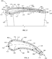
FIG. 4 is a plan schematic view of the weld path of the formation of the cladding layer ofFIG. 1 , according to an embodiment of the present disclosure. -
FIG. 5 is a perspective view of an article having a cladding layer following an alternative weld path toFIGS. 1-4 , according to an embodiment of the present disclosure. -
FIG. 6 is a plan schematic view of the alternative weld path ofFIG. 5 , according to an embodiment of the present disclosure. -
FIG. 7 is a cross-sectional view of the article formed inFIG. 2 wherein the substrate includes a surface layer of surface material, according to an embodiment of the present disclosure. -
FIG. 8 is a cross-sectional view of the article formed inFIG. 2 wherein the surface of the substrate has the same composition as the substrate itself, according to an embodiment of the present disclosure. - Wherever possible, the same reference numbers will be used throughout the drawings to represent the same parts.
- Provided are exemplary methods for forming article, methods for forming turbine buckets, and turbine buckets. Embodiments of the present disclosure, in comparison to articles and methods not utilizing one or more features disclosed herein, decrease costs, increase process control, increase process efficiency, increase process speed, increase repeatability, increase cladding layer thickness ranges, decrease squealer tip composition complexity, decrease or eliminate crack occurrence, or combinations thereof.
- As used herein, "GTD 111" refers to an alloy including a composition, by weight, of about 13.5% to about 14.5% chromium, about 9% to about 10% cobalt, about 3.3% to about 4.3% tungsten, about 4.4% to about 5.4% titanium, about 2.5% to about 3.5% aluminum, about 0.05% to about 0.15% iron, about 2.3% to about 3.3% tantalum, about 1.1% to about 2.1% molybdenum, about 0.05% to about 0.15% carbon, and a balance of nickel. GTD 111 is available from General Electric Company, 1 River Road, Schenectady, NY 12345.
- As used herein, "GTD 222" refers to an alloy including a composition, by weight, of about 22.5% to about 24.5% chromium, about 18% to about 20% cobalt, about 1.5% to about 2.5% tungsten, about 0.3% to about 1.3% niobium, about 1.8% to about 2.8% titanium, about 0.7% to about 1.7% aluminum, about 0.5% to about 1.5% tantalum, about 0.15% to about 0.35% silicon, about 0.05% to about 0.15% manganese, and a balance of nickel. GTD 222 is available from General Electric Company, 1 River Road, Schenectady, NY 12345.
- As used herein, "HAYNES 214" refers to an alloy including a composition, by weight, of about 15% to about 17% chromium, about 4% to about 5% aluminum, about 2% to about 4% iron, about 0.002% to about 0.04% yttrium, up to about 0.5% manganese, up to about 0.2% silicon, up to about 0.1% zirconium, up to about 0.05% carbon, up to about 0.5% tungsten, up to about 2% cobalt, up to about 0.15% niobium, up to about 0.5% titanium, up to about 0.5% molybdenum, up to about 0.01% boron, and a balance of nickel. HAYNES 214 is available from H.C. Starck, 45 Industrial Place, Newton, Massachusetts 02461-1951.
- As used herein, "HAYNES 230" refers to an alloy including a composition, by weight, of about 21% to about 23% chromium, about 13% to about 15% tungsten, about 1% to about 3% molybdenum, about 0.25% to about 0.75% manganese, about 0.2% to about 0.6% silicon, about 0.1% to about 0.5% aluminum, about 0.05% to about 0.15% carbon, about 0.01% to about 0.03% lanthanum, up to about 3% iron, up to about 5% cobalt, up to about 0.5% niobium, up to about 0.1% titanium, up to about 0.015% boron, and a balance of nickel. HAYNES 230 is available from Haynes International, 1020 W. Park Avenue, Kokomo, Indiana, 46904-9013.
- As used herein, "INCONEL 625" refers to an alloy including a composition, by weight, of about 20% to about 23% chromium, about 8% to about 10% molybdenum, about 3.15% to about 4.15% niobium and tantalum, up to about 5% iron, up to about 0.1% carbon, up to about 0.5% manganese, up to about 0.5% silicon, up to about 0.015% phosphorous, up to about 0.015% sulfur, up to about 0.4% aluminum, up to about 0.4% titanium, up to about 1% cobalt, and a balance of nickel. INCONEL 625 is available from Special Metals Corporation, 3200 Riverside Drive, Huntington, West Virginia 25720.
- As used herein, "INCONEL 718" refers to an alloy including a composition, by weight, of about 17% to about 21% chromium, about 50% to about 55% nickel and cobalt, about 4.75% to about 5.5% niobium and tantalum, about 2.8% to about 3.3% molybdenum, about 0.65% to about 1.15% titanium, about 0.2% to about 0.8% aluminum, up to about 1% cobalt, up to about 0.08% carbon, up to about 0.35% manganese, up to about 0.35% silicon, up to about 0.015% phosphorous, up to about 0.015% sulfur, up to about 0.006% boron, up to about 0.3% copper, and a balance of iron. INCONEL 718 is available from Special Metals Corporation, 3200 Riverside Drive, Huntington, West Virginia 25720.
- As used herein, "MAR-M-247" refers to an alloy including a composition, by weight, of about 5.4% to about 5.7% aluminum, about 8% to about 8.5% chromium, about 9% to about 9.5% cobalt, about 9.3% to about 9.7% tungsten, about 0.05% to about 0.15% manganese, about 0.15% to about 0.35% silicon, about 0.06% to about 0.09% carbon, and a balance of nickel. MAR-M-247 is available from MetalTek International, 905 E. St. Paul Avenue, Waukesha, Wisconsin 53188.
- As used herein, "MERL 72" refers to an alloy including a composition, by weight, of about 14% to about 16% nickel, about 19% to about 21% chromium, about 8% to about 10% tungsten, about 4.0% to about 4.8% aluminum, about 0.1% to about 0.3% titanium, about 2% to about 4% tantalum, about 0.25% to about 0.45% carbon, about 0.5% to about 1.5% hafnium, about 0.35% to about 0.55% yttrium, and a balance of cobalt. MERL 72 is available from Polymet Corporation, 7397 Union Centre Boulevard, West Chester, Ohio, 45014.
- As used herein, "
René 108" refers to an alloy including a composition, by weight, of about 7.9% to about 8.9% chromium, about 9% to about 10% cobalt, about 5% to about 6% aluminum, about 0.5% to about 0.9% titanium, about 9% to about 10% tungsten, about 0.3% to about 0.7% molybdenum, about 2.5% to about 3.5% tantalum, about 1% to about 2% hafnium and a balance of nickel.René 108 is commercially available under that designation. - As used herein, "Rene N4" refers to an alloy including a composition, by weight, of about 9% to about 10.5% chromium, about 7% to about 8% cobalt, about 3.7% to about 4.7% aluminum, about 3% to about 4% titanium, about 1% to about 2% molybdenum, about 5% to about 7% tungsten, about 4.3% to about 5.3% tantalum, about 0.3% to about 0.7% niobium, about 0.1% to about 0.2% hafnium, and a balance of nickel. René N4 is commercially available under that designation.
- As used herein, "René N5" refers to an alloy including a composition, by weight, of about 7% to about 8% cobalt, about 6% to about 8% chromium, about 5.5% to about 7.5% tantalum, about 5.2% to about 7.2% aluminum, about 4% to about 6% tungsten, about 2.5% to about 3.5% rhenium, about 1% to about 2% molybdenum, about 0.1% to about 0.2% hafnium, and a balance of nickel. René N5 is commercially available under that designation.
- Referring to
FIGS. 1-6 , in one embodiment, a method for forming anarticle 200 includes laser welding apowder 104 of ametal alloy 120 to asurface 102 of asubstrate 100 along aweld path 400, forming aweld bead 106 of themetal alloy 120 having aweld bead width 108 and aweld bead height 110. Theweld path 400 propagates along aweld direction 112, forming acladding layer 202 of themetal alloy 120 disposed on thesurface 102 having acladding layer thickness 204. Theweld path 400 oscillates essentially nonparallel relative to areference line 122, establishing acladding width 114 wider than theweld bead width 108. Theweld bead 106 contacts itself along each oscillation such that thecladding layer 202 is continuous. Thecladding layer 202 is essentially free of cracks. In a further embodiment, forming thecladding layer 202 is free of gas tungsten arc welding. - The
reference line 122 may be any suitable line, including, but not limited to, theweld direction 112, a chord line of thesubstrate 100, a center line of thesubstrate 100, or combinations thereof. - As used herein, the
weld path 400 oscillating "essentially nonparallel" relative to thereference line 122 indicates that between each turn of theweld path 400, theweld path 400 progresses at an angle which is not parallel with respect to thereference line 122, excepting that in embodiments in which thereference line 122 progresses around a curve, there may a point along the curve at which theweld path 400 between two turns of theweld path 400 is parallel with thereference line 122. As used herein "not parallel" indicates an angle between 1° to 179°, alternatively between about 30° to about 150°, alternatively between about 60° to about 120°. - In one embodiment, the
weld path 400 oscillates essentially perpendicular to thereference line 122. As used herein, "essentially perpendicular" indicates that that between each turn of theweld path 400, theweld path 400 progresses at an angle at less than about a 15° variance, alternatively less than about a 10° variance, alternatively less than about a 5° variance, excepting that in embodiments in which theweld direction 112 progresses around a curve, the essentially perpendicular oscillation of theweld path 400 may be oblique or even perpendicular to theweld direction 112 at points along the curve. - In one embodiment (
FIGS. 1-4 ), the alignment of the oscillatingweld path 400 between each turn of theweld path 400 is essentially constant, varying by less than about 15° at each oscillation, alternatively less than about 10°, alternatively less than about 5°, alternatively less than about 1°. In another embodiment (FIGS. 5 and 6 ), the alignment of the oscillatingweld path 400 between each turn of theweld path 400 is maintained essentially perpendicular to theweld direction 112 at that point. - As used herein, the
cladding layer 202 being "continuous" indicates that there are no gaps between the oscillations of theweld bead 106 along theweld path 400, but allows that theweld path 400 may be deliberately arranged to establish omittedregions 208 free of thecladding layer 202. - As used herein, "essentially" free of cracks indicates that any cracks are less than about 0.03 inches in largest dimension, alternatively less than about 0.02 inches in largest dimension, alternatively less than about 0.01 inches in largest dimension.
- The
powder 104 may be applied at any suitable flow rate, including, but not limited to, at a flow rate between about 3 g/min to about 9 g/min, alternatively between about 4 g/min to about 8 g/min, alternatively between about 3 g/min to about 5 g/min, alternatively between about 4 g/min to about 6 g/min, alternatively between about 5 g/min to about 7 g/min, alternatively between about 6 g/min to about 8 g/min, alternatively between about 4.8 g/min to about 5.2 g/min. The flow rate is related to the capture rate ofpowder 104. Themore powder 104 which is captured by the laser welding, the lower the flow rate of thepowder 104 may be. Conversely, the lower the rate of capture of thepowder 104, the higher the flow rate of thepowder 104 should be to compensate. - In one embodiment, the
powder 104 is deposited (captured to form the weld bead 106) at a capture rate of between about 40 g/in3 to about 265 g/in3, alternatively between about 44 g/in3 to about 244 g/in3, alternatively between about 60 g/in3 to about 200 g/in3, alternatively between about 65 g/in3 to about 175 g/in3, alternatively between about 70 g/in3 to about 150 g/in3, alternatively between about 75 g/in3 to about 137 g/in3, alternatively between about 40 g/in3 to about 90 g/in3, alternatively between about 65 g/in3 to about 115 g/in3, alternatively between about 90 g/in3 to about 140 g/in3, alternatively between about 115 g/in3 to about 165 g/in3, alternatively between about 140 g/in3 to about 190 g/in3, alternatively between about 165 g/in3 to about 215 g/in3, alternatively between about 190 g/in3 to about 240 g/in3, alternatively between about 215 g/in3 to about 265 g/in3. - In one embodiment, the
metal alloy 120 is an HTW alloy. Suitable HTW alloys include, but are not limited to, HAYNES 214. In one embodiment, themetal alloy 120 includes HAYNES 214. In a further embodiment themetal alloy 120 consists essentially of HAYNES 214. As used herein, "consists essentially of' indicates that the inclusion of impurities, the presence of oxidation contaminants, and variances in composition are permissible so long as the properties of the alloy relevant to the alloy's performance in the article, including, but not limited to, melting temperature, oxidation resistance, ductility, and strength, are not negatively and materially affected. In yet a further embodiment, the alloy consists of HAYNES 214. - The laser welding may include any suitable laser energy density, and may be performed with any suitable
laser welding apparatus 116. In one embodiment, the laser welding includes thelaser welding apparatus 116 imparting a laser energy density of at least about 11 kJ/cm2. In a further embodiment the laser energy density is between about 11.5 kJ/cm2 to about 20.3 kJ/cm2, alternatively between about 15 kJ/cm2 to about 20.3 kJ/cm2. Thelaser welding apparatus 116 may emit any suitable beam diameter, including, but not limited to, a beam diameter of between about 0.01 inches to about 0.2 inches, alternatively between about 0.02 inches to about 0.1 inches, alternatively between about 0.03 inches to about 0.08 inches, alternatively between about 0.04 inches to about 0.07 inches, alternatively between about 0.04 inches to about 0.06 inches, alternatively between about 0.045 inches to about 0.065 inches, alternatively between about 0.05 inches to about 0.7 inches, alternatively about 0.05 inches, alternatively about 0.55 inches, alternatively about 0.06 inches. The energy distribution of thelaser welding apparatus 116 may include any suitable profile, including, but not limited to, top hat and gaussian. In one embodiment (shown), thelaser welding apparatus 116 emits a laser which is about coaxial with thepowder 104 as the laser andpowder 104 are directed toward thesurface 102. In another embodiment (not shown), thelaser welding apparatus 116 emits a laser which is off-axis with thepowder 104 as the laser andpowder 104 are directed toward thesurface 102 - Laser welding the
powder 104 of themetal alloy 120 to thesurface 102 of the substrate along theweld path 400 may include any suitable welding speed, including, but not limited to, a welding speed between about 5 ipm to about 20 ipm, alternatively between about 5 ipm to about 15 ipm, alternatively between about 7.5 ipm to about 17.5 ipm, alternatively between about 10 ipm to about 20 ipm, alternatively between about 5 ipm to about 10 ipm, alternatively between about 7.5 ipm to about 12.5 ipm, alternatively between about 10 ipm to about 15 ipm, alternatively between about 12.5 ipm to about 17.5 ipm, alternatively between about 15 ipm to about 20 ipm. - The
substrate 100 may be any suitable object, including, but not limited to, a turbine component. Suitable turbine components include, but are not limited to, turbine hot gas path components,turbine buckets 118, turbine nozzles, turbine shrouds, turbine combustors, turbine combustion liners, turbine transition pieces, and combinations thereof. In one embodiment (shown), thesubstrate 100 is aturbine bucket 118, thearticle 200 is aturbine bucket 118 including asquealer tip 206, and thecladding layer 202 forms at least a portion of thesquealer tip 206. Other embodiments (not shown) include, but are not limited to, wherein thesubstrate 100 is aturbine bucket 118 and thecladding layer 202 forms at least a portion of an angel wing, wherein thesubstrate 100 is aturbine bucket 118 and thecladding layer 202 forms at least a portion of the trailingedge 402, wherein thesubstrate 100 is a turbine nozzle and thecladding layer 202 forms at least a portion of a nozzle edge, and wherein thesubstrate 100 includes a narrow or sharp feature subject to higher oxidation than the remainder of thesubstrate 100 and thecladding layer 202 forms the extremity of the narrow or sharp feature. - Referring to
FIGS. 7 and 8 , in one embodiment (FIG. 7 ), thesurface 102 of thesubstrate 100 includes asurface layer 700 of asurface material 702 compositionally distinct from amaterial composition 704 of thesubstrate 100. The surface material may include any suitable alloy composition, including, but not limited to HAYNES 230, INCONEL 625, MERL 72, or combinations thereof. In another embodiment (FIG. 8 ), thesurface 102 of thesubstrate 100 consists essentially of, alternatively consists of, thematerial composition 704 of thesubstrate 100, and thepowder 104 of themetal alloy 120 is welded directly to thesurface 102 of thesubstrate 100. - The
material composition 704 of thesubstrate 100 may include any suitable composition, including, but not limited to, steels, mild steels, superalloys, nickel-based superalloys, cobalt-based superalloys, GTD 111, GTD 222, INCONEL 718, MAR-M-247, René N4, René N5,René 108, or combinations thereof. - Referring again to
FIGS. 4 and6 , in one embodiment, theweld path 400 commences at a trailingedge 402 of theturbine bucket 118, proceeds across a trailingedge width 404 of the trailingedge 402, and then proceeds around aperiphery 406 of theturbine bucket 118 along one of asuction side 408 and apressure side 410, through aleading edge 412, and back along the other of thesuction side 408 and thepressure side 410 until returning to the trailingedge 402. - Referring to
FIGS. 1, 2 ,5 , and7 , in one embodiment, forming thecladding layer 202 consists essentially of applying a single layer of themetal alloy 120, and thecladding layer thickness 204 is about theweld bead height 110. As used herein, "consisting essentially of' indicates that thecladding layer 202 itself is formed of the single layer of themetal alloy 120, but allows that additional and compositionally distinct coatings may be applied to thecladding layer 202, and that finishing techniques may be applied to thecladding layer 202, including, but not limited to, machining thecladding layer 202 to achieve net shape, which may reduce thecladding layer thickness 204. - The
cladding layer thickness 204 may be any suitable thickness, including, but not limited to between about 0.02 inches to about 0.15 inches, alternatively between about 0.04 inches to about 0.13 inches, alternatively between about 0.07 inches to about 0.1 inches, alternatively between about 0.02 inches to about 0.5 inches, alternatively between about 0.04 inches to about 0.07 inches, alternatively between about 0.06 inches to about 0.09 inches, alternatively between about 0.08 inches to about 0.11 inches, alternatively between about 0.1 inches to about 0.13 inches, alternatively between about 0.12 inches to about 0.15 inches. - Referring to
FIGS. 1-3 and8 , in another embodiment, forming thecladding layer 202 includes applying afirst layer 300 of themetal alloy 120 to thesurface 102 of thesubstrate 100 by laser welding thepowder 104 of themetal alloy 120 to thesurface 102 of thesubstrate 100, and then applying asecond layer 302 of themetal alloy 120 to thefirst layer 300 of themetal alloy 120 by laser welding thepowder 104 of themetal alloy 120 to thefirst layer 300 of themetal alloy 120, such that thecladding layer thickness 204 is greater than theweld bead height 110. - Forming the
cladding layer 202 may further include applying at least one additional layer (not shown) of themetal alloy 120 sequentially by laser welding thepowder 104 of themetal alloy 120 to a previously applied layer of themetal alloy 120. - Forming the
cladding layer 202 by applying at least afirst layer 300 and asecond layer 302 of themetal alloy 120 may form acladding layer thickness 204 greater than the maximumweld bead height 110 of aweld bead 106. In one embodiment, thecladding layer thickness 204 is at least about 0.2 inches, alternatively at least about 0.3 inches, alternatively at least about 0.4 inches, alternatively at least about 0.5 inches, alternatively at least about 0.6 inches, alternatively at least about 0.7 inches, alternatively at least about 0.8 inches, alternatively at least about 0.9 inches, alternatively at least about 1 inch, alternatively between about 0.2 inches to about 0.8 inches, alternatively between about 0.3 inches to about 0.7 inches, alternatively between about 0.2 inches to about 0.4 inches, alternatively between about 0.3 inches to about 0.5 inches, alternatively between about 0.4 inches to about 0.6 inches, alternatively between about 0.5 inches to about 0.7 inches, alternatively between about 0.6 inches to about 0.8 inches. - While the invention has been described with reference to a preferred embodiment, it will be understood by those skilled in the art that various changes may be made and equivalents may be substituted for elements thereof without departing from the scope of the invention. In addition, many modifications may be made to adapt a particular situation or material to the teachings of the invention without departing from the essential scope thereof. Therefore, it is intended that the invention not be limited to the particular embodiment disclosed as the best mode contemplated for carrying out this invention, but that the invention will include all embodiments falling within the scope of the appended claims.
Claims (15)
- A method for forming an article (200), comprising:laser welding a powder (104) of a metal alloy (120) to a surface (102) of a substrate (100) along a weld path (400), forming a weld bead (106) of the metal alloy (120) having a weld bead width (108) and a weld bead height (108); andpropagating the weld path (400) along a weld direction (112), forming a cladding layer (202) of the metal alloy (120) disposed on the surface (102) having a cladding layer thickness (204), wherein:the metal alloy (120) is a hard-to-weld (HTW) alloy;the laser welding includes a laser energy density of at least 11 kJ/cm2;laser welding the powder (104) of the metal alloy (120) to the surface (102) of the substrate (100) along the weld path (400) includes a welding speed between 5 ipm to 20 ipm;the weld path (400) oscillates essentially nonparallel relative to a reference line (122), establishing a cladding width (114) wider than the weld bead width (108); andthe weld bead (106) contacts itself along each oscillation such that the cladding layer (202) is continuous.
- The method of claim 1, wherein the article (200) is a turbine bucket (118) including a squealer tip (206), and the cladding layer (202) forms at least a portion of the squealer tip (206).
- The method of claim 1 or claim 2, wherein the weld path (400) commences at a trailing edge (402) of the turbine bucket (118), proceeds across a trailing edge width (404) of the trailing edge (402), and then proceeds around a periphery (406) of the turbine bucket (118) along one of a suction side (408) and a pressure side (410), through a leading edge (412), and back along the other of the suction side (408) and the pressure side (410) until returning to the trailing edge (402).
- The method of any preceding claim, wherein the reference line (122) is selected from the group consisting of a weld direction (112), a center line, a chord line, and combinations thereof.
- The method of any preceding claim, wherein the metal alloy (104) includes, by weight:15% to 17% chromium;4% to 5% aluminum;2% to 4% iron;0.002% to 0.04% yttrium;up to 0.5% manganese;up to 0.2% silicon;up to 0.1% zirconium;up to 0.05% carbon;up to 0.5% tungsten;up to 2% cobalt;up to 0.15% niobium;up to 0.5% titanium;up to 0.5% molybdenum;up to 0.01% boron; anda balance of nickel;
- The method of any preceding claim, wherein the surface (102) of the substrate (100) includes a surface layer (700) of a surface material (702) selected from the group consisting of:an alloy composition including, by weight:21% to 23% chromium;13% to 15% tungsten;1% to 3% molybdenum;0.25% to 0.75% manganese;0.2% to 0.6% silicon;0.1% to 0.5% aluminum;0.05% to 0.15% carbon;0.01% to 0.03% lanthanum;up to 3% iron;up to 5% cobalt;up to 0.5% niobium;up to 0.1% titanium;up to 0.015% boron; anda balance of nickel;an alloy composition including, by weight:20% to 23% chromium;8% to 10% molybdenum;3.15% to 4.15% niobium and tantalum;up to 5% iron;up to 0.1% carbon;up to 0.5% manganese;up to 0.5% silicon;up to 0.015% phosphorous;up to 0.015% sulfur;up to 0.4% aluminum;up to 0.4% titanium;up to 1% cobalt; anda balance of nickel;an alloy composition including, by weight:14% to 16% nickel;19% to 21% chromium;8% to 10% tungsten;4.0% to 4.8% aluminum;0.1% to 0.3% titanium;2% to 4% tantalum;0.25% to 0.45% carbon;0.5% to 1.5% hafnium;0.35% to 0.55% yttrium; anda balance of cobalt; andcombinations thereof.
- The method of any preceding claim, wherein the substrate (100) includes a material composition (704), the surface (102) of the substrate (100) consists essentially of the material composition (704) of the substrate (100), and the powder (104) of the metal alloy (120) is laser welded directly to the surface (102) of the substrate (100).
- The method of any preceding claim, wherein the substrate (100) includes a material composition (704) selected from the group consisting of:steels;mild steels;superalloys;nickel-based superalloys;cobalt-based superalloys;an alloy composition including, by weight:9% to 10.5% chromium;7% to 8% cobalt;3.7% to 4.7% aluminum;3% to 4% titanium;1% to 2% molybdenum;5% to 7% tungsten;4.3% to 5.3% tantalum;0.3% to 0.7% niobium;0.1% to 0.2% hafnium; anda balance of nickel;an alloy composition including, by weight:13.5% to 14.5% chromium;9% to 10% cobalt;3.3% to 4.3% tungsten;4.4% to 5.4% titanium;2.5% to 3.5% aluminum;0.05% to 0.15% iron;2.3% to 3.3% tantalum;1.1% to 2.1% molybdenum;0.05% to 0.15% carbon; anda balance of nickel;an alloy composition including, by weight:22.5% to 24.5% chromium;18% to 20% cobalt;1.5% to 2.5% tungsten;0.3% to 1.3% niobium;1.8% to 2.8% titanium;0.7% to 1.7% aluminum;0.5% to 1.5% tantalum;0.15% to 0.35% silicon;0.05% to 0.15% manganese; anda balance of nickel;an alloy composition including, by weight:17% to 21% chromium;50% to 55% nickel and cobalt;4.75% to 5.5% niobium and tantalum;2.8% to 3.3% molybdenum;0.65% to 1.15% titanium;0.2% to 0.8% aluminum;up to 1% cobalt;up to 0.08% carbon;up to 0.35% manganese;up to 0.35% silicon;up to 0.015% phosphorous;up to 0.015% sulfur;up to 0.006% boron;up to 0.3% copper; anda balance of iron;an alloy composition including, by weight:5.4% to 5.7% aluminum;8% to 8.5% chromium;9% to 9.5% cobalt;9.3% to 9.7% tungsten;0.05% to 0.15% manganese;0.15% to 0.35% silicon;0.06% to 0.09% carbon; anda balance of nickel;an alloy composition including, by weight:7% to 8% cobalt;6% to 8% chromium;5.5% to 7.5% tantalum;5.2% to 7.2% aluminum;4% to 6% tungsten;2.5% to 3.5% rhenium;1% to 2% molybdenum;0.1% to 0.2% hafnium; anda balance of nickel;an alloy composition including, by weight:7.9% to 8.9% chromium;9% to 10% cobalt;5% to 6% aluminum;0.5% to 0.9% titanium;9% to 10% tungsten;0.3% to 0.7% molybdenum;2.5% to 3.5% tantalum;1% to 2% hafnium; anda balance of nickel; andcombinations thereof.
- The method of any preceding claim, wherein the laser energy density is between 11.5 kJ/cm2 to 20.3 kJ/cm2.
- The method of any preceding claim, wherein the powder (104) is applied at a flow rate between 4 g/min to 6 g/min.
- The method of any preceding claim, wherein forming the cladding layer (202) consists essentially of applying a single layer of the metal alloy (120), and the cladding layer thickness (204) is the weld bead height (110).
- The method of any preceding claim, wherein forming the cladding layer (202) includes applying a first layer (300) of the metal alloy (120) to the surface (102) of the substrate (100) by laser welding the powder (104) of the metal alloy (120) to the surface (102) of the substrate (100), and then applying a second layer (302) of the metal alloy (120) to the first layer (300) of the metal alloy (120) by laser welding the powder (104) of the metal alloy (120) to the first layer (300) of the metal alloy (120), such that the cladding layer thickness (204) is greater than the weld bead height (110).
- The method of any preceding claim, wherein the cladding layer thickness (204) is between 0.02 inches to 0.15 inches.
- The method of any of claims 1 to 12, wherein the cladding layer thickness (204) is at least 0.2 inches.
- A turbine bucket (118), comprising:a squealer tip (206), wherein:the squealer tip (206) includes a cladding layer (202) consisting essentially of, by weight:15% to 17% chromium;4% to 5% aluminum;2% to 4% iron;0.002% to 0.04% yttrium;up to 0.5% manganese;up to 0.2% silicon;up to 0.1% zirconium;up to 0.05% carbon;up to 0.5% tungsten;up to 2% cobalt;up to 0.15% niobium;up to 0.5% titanium;up to 0.5% molybdenum;up to 0.01% boron; anda balance of nickel; andthe cladding layer (202) includes a cladding layer thickness (204) of at least 0.2 inches.
Applications Claiming Priority (1)
| Application Number | Priority Date | Filing Date | Title |
|---|---|---|---|
| US15/713,857 US20190091802A1 (en) | 2017-09-25 | 2017-09-25 | Method for forming article, method for forming turbine bucket, and turbine bucket |
Publications (2)
| Publication Number | Publication Date |
|---|---|
| EP3466602A1 true EP3466602A1 (en) | 2019-04-10 |
| EP3466602B1 EP3466602B1 (en) | 2024-06-26 |
Family
ID=63517751
Family Applications (1)
| Application Number | Title | Priority Date | Filing Date |
|---|---|---|---|
| EP18192703.9A Active EP3466602B1 (en) | 2017-09-25 | 2018-09-05 | Method for forming an article |
Country Status (5)
| Country | Link |
|---|---|
| US (1) | US20190091802A1 (en) |
| EP (1) | EP3466602B1 (en) |
| JP (1) | JP7246881B2 (en) |
| CN (1) | CN109554703A (en) |
| HU (1) | HUE068000T2 (en) |
Families Citing this family (9)
| Publication number | Priority date | Publication date | Assignee | Title |
|---|---|---|---|---|
| EP4031947B1 (en) | 2019-09-18 | 2025-01-15 | Autodesk, Inc. | Hybrid additive and subtractive manufacturing |
| CN111074269A (en) * | 2020-01-02 | 2020-04-28 | 沈阳中钛装备制造有限公司 | Titanium alloy wear-resistant coating and preparation method thereof |
| CN111575538B (en) * | 2020-06-29 | 2021-06-15 | 中天上材增材制造有限公司 | High-tungsten-nickel-based alloy powder suitable for laser cladding |
| US11743670B2 (en) | 2020-12-18 | 2023-08-29 | Qualcomm Incorporated | Correlation-based rendering with multiple distributed streams accounting for an occlusion for six degree of freedom applications |
| CN112975130A (en) * | 2021-03-11 | 2021-06-18 | 上海思客琦智能装备科技股份有限公司 | Welding process of aluminum alloy, copper alloy and nickel-plated copper for lithium battery tab |
| CN113637873B (en) * | 2021-08-18 | 2023-03-31 | 沈阳大陆激光先进制造技术创新有限公司 | Functional layer alloy material for remanufacturing minimum flow valve sealing surface by utilizing laser technology and preparation method of cover |
| CN114360664A (en) * | 2021-12-09 | 2022-04-15 | 宁夏银星能源股份有限公司 | A laser single-pass cladding forming control method for alloy steel |
| US20250242409A1 (en) * | 2024-01-26 | 2025-07-31 | Rtx Corporation | Use of sacrificial surface during directed energy deposition repair process |
| CN119980218B (en) * | 2025-04-11 | 2025-11-21 | 浙江摩克激光智能装备有限公司 | A laser cladding powder and a method for laser cladding on aluminum alloy surfaces |
Citations (6)
| Publication number | Priority date | Publication date | Assignee | Title |
|---|---|---|---|---|
| US5160822A (en) * | 1991-05-14 | 1992-11-03 | General Electric Company | Method for depositing material on the tip of a gas turbine engine airfoil using linear translational welding |
| US6872912B1 (en) * | 2004-07-12 | 2005-03-29 | Chromalloy Gas Turbine Corporation | Welding single crystal articles |
| US20060049153A1 (en) * | 2004-09-08 | 2006-03-09 | Cahoon Christopher L | Dual feed laser welding system |
| US20120267347A1 (en) * | 2009-11-13 | 2012-10-25 | Nikolai Arjakine | Method for welding workpieces made of highly heat-resistant superalloys, including a particular mass feed rate of the welding filler material |
| EP3115147A1 (en) * | 2015-07-09 | 2017-01-11 | General Electric Company | Systems and methods for turbine blade repair |
| US20170182562A1 (en) * | 2012-11-08 | 2017-06-29 | Georgia Tech Research Corporation | Systems and methods for additive manufacturing and repair of metal components |
Family Cites Families (11)
| Publication number | Priority date | Publication date | Assignee | Title |
|---|---|---|---|---|
| US6332272B1 (en) * | 2000-01-07 | 2001-12-25 | Siemens Westinghouse Power Corporation | Method of repairing a turbine blade |
| US20070003416A1 (en) * | 2005-06-30 | 2007-01-04 | General Electric Company | Niobium silicide-based turbine components, and related methods for laser deposition |
| US20110293963A1 (en) * | 2010-05-25 | 2011-12-01 | Honeywell International Inc. | Coatings, turbine engine components, and methods for coating turbine engine components |
| US9283593B2 (en) * | 2011-01-13 | 2016-03-15 | Siemens Energy, Inc. | Selective laser melting / sintering using powdered flux |
| US9272369B2 (en) * | 2012-09-12 | 2016-03-01 | Siemens Energy, Inc. | Method for automated superalloy laser cladding with 3D imaging weld path control |
| WO2014120991A1 (en) * | 2013-01-31 | 2014-08-07 | Siemens Energy, Inc. | Selective laser melting / sintering using powdered flux |
| CN104955612A (en) * | 2013-01-31 | 2015-09-30 | 西门子能量股份有限公司 | Laser remelting repair method for superalloys using flux |
| US9815139B2 (en) * | 2014-01-22 | 2017-11-14 | Siemens Energy, Inc. | Method for processing a part with an energy beam |
| US10076786B2 (en) * | 2014-01-22 | 2018-09-18 | Siemens Energy, Inc. | Method for processing a part with an energy beam |
| US20150224607A1 (en) * | 2014-02-07 | 2015-08-13 | Siemens Energy, Inc. | Superalloy solid freeform fabrication and repair with preforms of metal and flux |
| US10946473B2 (en) * | 2015-05-14 | 2021-03-16 | General Electric Company | Additive manufacturing on 3-D components |
-
2017
- 2017-09-25 US US15/713,857 patent/US20190091802A1/en not_active Abandoned
-
2018
- 2018-09-05 EP EP18192703.9A patent/EP3466602B1/en active Active
- 2018-09-05 HU HUE18192703A patent/HUE068000T2/en unknown
- 2018-09-11 JP JP2018169270A patent/JP7246881B2/en active Active
- 2018-09-21 CN CN201811107920.8A patent/CN109554703A/en active Pending
Patent Citations (6)
| Publication number | Priority date | Publication date | Assignee | Title |
|---|---|---|---|---|
| US5160822A (en) * | 1991-05-14 | 1992-11-03 | General Electric Company | Method for depositing material on the tip of a gas turbine engine airfoil using linear translational welding |
| US6872912B1 (en) * | 2004-07-12 | 2005-03-29 | Chromalloy Gas Turbine Corporation | Welding single crystal articles |
| US20060049153A1 (en) * | 2004-09-08 | 2006-03-09 | Cahoon Christopher L | Dual feed laser welding system |
| US20120267347A1 (en) * | 2009-11-13 | 2012-10-25 | Nikolai Arjakine | Method for welding workpieces made of highly heat-resistant superalloys, including a particular mass feed rate of the welding filler material |
| US20170182562A1 (en) * | 2012-11-08 | 2017-06-29 | Georgia Tech Research Corporation | Systems and methods for additive manufacturing and repair of metal components |
| EP3115147A1 (en) * | 2015-07-09 | 2017-01-11 | General Electric Company | Systems and methods for turbine blade repair |
Also Published As
| Publication number | Publication date |
|---|---|
| US20190091802A1 (en) | 2019-03-28 |
| EP3466602B1 (en) | 2024-06-26 |
| JP2019089127A (en) | 2019-06-13 |
| CN109554703A (en) | 2019-04-02 |
| JP7246881B2 (en) | 2023-03-28 |
| HUE068000T2 (en) | 2024-12-28 |
Similar Documents
| Publication | Publication Date | Title |
|---|---|---|
| EP3466602B1 (en) | Method for forming an article | |
| US11033987B2 (en) | Hybrid article, method for forming hybrid article and method for welding | |
| US8726501B2 (en) | Method of welding single crystal turbine blade tips with an oxidation-resistant filler material | |
| EP2995410A1 (en) | Method of blade tip repair | |
| US10086459B2 (en) | Method for forming hybrid article | |
| EP3412784B1 (en) | Method of treating superalloy articles | |
| EP2684981B1 (en) | A coating/repairing process using electrospark with PSP rod | |
| EP3332898B1 (en) | Heterogeneous composition, article comprising heterogeneous composition, and method for forming article | |
| EP3159425A1 (en) | Article, turbine component and airfoil refurbishment methods | |
| WO2019014445A1 (en) | Method of repairing an article and associated article | |
| CN106163733A (en) | Guide by means of vibration beam and laser overlaying welding is carried out to resistant to elevated temperatures superalloy | |
| US20110000890A1 (en) | Potential-Free Wire Heating During Welding and Apparatus Therefor | |
| JP2016117099A (en) | Weld filler for superalloys | |
| EP3173175A1 (en) | An article treatment method and treated article | |
| US10618128B2 (en) | Method for closing a hole in a metal article | |
| US10265792B2 (en) | Sinter-bonded hybrid article, method for forming hybrid article, and method for closing aperture | |
| US10035329B2 (en) | Hybrid article, method for forming hybrid article, and method for closing aperture | |
| EP3184658B1 (en) | Co alloy, welded article and welding process | |
| US10603734B2 (en) | Method for hardfacing a metal article | |
| EP2564978B1 (en) | Filler metal chemistry for improved weldability of super alloys | |
| US10610944B2 (en) | Method for closing a plurality of holes in a metal article |
Legal Events
| Date | Code | Title | Description |
|---|---|---|---|
| PUAI | Public reference made under article 153(3) epc to a published international application that has entered the european phase |
Free format text: ORIGINAL CODE: 0009012 |
|
| STAA | Information on the status of an ep patent application or granted ep patent |
Free format text: STATUS: THE APPLICATION HAS BEEN PUBLISHED |
|
| AK | Designated contracting states |
Kind code of ref document: A1 Designated state(s): AL AT BE BG CH CY CZ DE DK EE ES FI FR GB GR HR HU IE IS IT LI LT LU LV MC MK MT NL NO PL PT RO RS SE SI SK SM TR |
|
| AX | Request for extension of the european patent |
Extension state: BA ME |
|
| STAA | Information on the status of an ep patent application or granted ep patent |
Free format text: STATUS: REQUEST FOR EXAMINATION WAS MADE |
|
| 17P | Request for examination filed |
Effective date: 20191010 |
|
| RBV | Designated contracting states (corrected) |
Designated state(s): AL AT BE BG CH CY CZ DE DK EE ES FI FR GB GR HR HU IE IS IT LI LT LU LV MC MK MT NL NO PL PT RO RS SE SI SK SM TR |
|
| STAA | Information on the status of an ep patent application or granted ep patent |
Free format text: STATUS: EXAMINATION IS IN PROGRESS |
|
| 17Q | First examination report despatched |
Effective date: 20211206 |
|
| RAP1 | Party data changed (applicant data changed or rights of an application transferred) |
Owner name: GENERAL ELECTRIC TECHNOLOGY GMBH |
|
| RIC1 | Information provided on ipc code assigned before grant |
Ipc: B23K 101/00 20060101ALN20231110BHEP Ipc: C22C 19/07 20060101ALI20231110BHEP Ipc: C22C 19/05 20060101ALI20231110BHEP Ipc: B23K 35/02 20060101ALI20231110BHEP Ipc: B23K 26/342 20140101ALI20231110BHEP Ipc: B23K 26/30 20140101ALI20231110BHEP Ipc: B23K 26/08 20140101ALI20231110BHEP Ipc: B23K 35/30 20060101ALI20231110BHEP Ipc: B23K 26/00 20140101ALI20231110BHEP Ipc: B23K 26/144 20140101ALI20231110BHEP Ipc: B23K 26/34 20140101AFI20231110BHEP |
|
| RIC1 | Information provided on ipc code assigned before grant |
Ipc: B23K 101/00 20060101ALN20231121BHEP Ipc: C22C 19/07 20060101ALI20231121BHEP Ipc: C22C 19/05 20060101ALI20231121BHEP Ipc: B23K 35/02 20060101ALI20231121BHEP Ipc: B23K 26/342 20140101ALI20231121BHEP Ipc: B23K 26/30 20140101ALI20231121BHEP Ipc: B23K 26/08 20140101ALI20231121BHEP Ipc: B23K 35/30 20060101ALI20231121BHEP Ipc: B23K 26/00 20140101ALI20231121BHEP Ipc: B23K 26/144 20140101ALI20231121BHEP Ipc: B23K 26/34 20140101AFI20231121BHEP |
|
| GRAP | Despatch of communication of intention to grant a patent |
Free format text: ORIGINAL CODE: EPIDOSNIGR1 |
|
| STAA | Information on the status of an ep patent application or granted ep patent |
Free format text: STATUS: GRANT OF PATENT IS INTENDED |
|
| INTG | Intention to grant announced |
Effective date: 20240104 |
|
| RIC1 | Information provided on ipc code assigned before grant |
Ipc: B23K 101/00 20060101ALN20231219BHEP Ipc: C22C 19/07 20060101ALI20231219BHEP Ipc: C22C 19/05 20060101ALI20231219BHEP Ipc: B23K 35/02 20060101ALI20231219BHEP Ipc: B23K 26/342 20140101ALI20231219BHEP Ipc: B23K 26/30 20140101ALI20231219BHEP Ipc: B23K 26/08 20140101ALI20231219BHEP Ipc: B23K 35/30 20060101ALI20231219BHEP Ipc: B23K 26/00 20140101ALI20231219BHEP Ipc: B23K 26/144 20140101ALI20231219BHEP Ipc: B23K 26/34 20140101AFI20231219BHEP |
|
| RIN1 | Information on inventor provided before grant (corrected) |
Inventor name: WOOLRIDGE, JILLIAN JAMISON Inventor name: HULLENDER, ROBERT TRENT |
|
| GRAJ | Information related to disapproval of communication of intention to grant by the applicant or resumption of examination proceedings by the epo deleted |
Free format text: ORIGINAL CODE: EPIDOSDIGR1 |
|
| STAA | Information on the status of an ep patent application or granted ep patent |
Free format text: STATUS: EXAMINATION IS IN PROGRESS |
|
| GRAP | Despatch of communication of intention to grant a patent |
Free format text: ORIGINAL CODE: EPIDOSNIGR1 |
|
| STAA | Information on the status of an ep patent application or granted ep patent |
Free format text: STATUS: GRANT OF PATENT IS INTENDED |
|
| INTC | Intention to grant announced (deleted) | ||
| RIC1 | Information provided on ipc code assigned before grant |
Ipc: B23K 101/00 20060101ALN20240222BHEP Ipc: C22C 19/07 20060101ALI20240222BHEP Ipc: C22C 19/05 20060101ALI20240222BHEP Ipc: B23K 35/02 20060101ALI20240222BHEP Ipc: B23K 26/342 20140101ALI20240222BHEP Ipc: B23K 26/30 20140101ALI20240222BHEP Ipc: B23K 26/08 20140101ALI20240222BHEP Ipc: B23K 35/30 20060101ALI20240222BHEP Ipc: B23K 26/00 20140101ALI20240222BHEP Ipc: B23K 26/144 20140101ALI20240222BHEP Ipc: B23K 26/34 20140101AFI20240222BHEP |
|
| INTG | Intention to grant announced |
Effective date: 20240318 |
|
| GRAS | Grant fee paid |
Free format text: ORIGINAL CODE: EPIDOSNIGR3 |
|
| GRAA | (expected) grant |
Free format text: ORIGINAL CODE: 0009210 |
|
| STAA | Information on the status of an ep patent application or granted ep patent |
Free format text: STATUS: THE PATENT HAS BEEN GRANTED |
|
| AK | Designated contracting states |
Kind code of ref document: B1 Designated state(s): AL AT BE BG CH CY CZ DE DK EE ES FI FR GB GR HR HU IE IS IT LI LT LU LV MC MK MT NL NO PL PT RO RS SE SI SK SM TR |
|
| REG | Reference to a national code |
Ref country code: GB Ref legal event code: FG4D |
|
| REG | Reference to a national code |
Ref country code: CH Ref legal event code: EP |
|
| REG | Reference to a national code |
Ref country code: DE Ref legal event code: R096 Ref document number: 602018070953 Country of ref document: DE |
|
| PG25 | Lapsed in a contracting state [announced via postgrant information from national office to epo] |
Ref country code: BG Free format text: LAPSE BECAUSE OF FAILURE TO SUBMIT A TRANSLATION OF THE DESCRIPTION OR TO PAY THE FEE WITHIN THE PRESCRIBED TIME-LIMIT Effective date: 20240626 |
|
| PG25 | Lapsed in a contracting state [announced via postgrant information from national office to epo] |
Ref country code: FI Free format text: LAPSE BECAUSE OF FAILURE TO SUBMIT A TRANSLATION OF THE DESCRIPTION OR TO PAY THE FEE WITHIN THE PRESCRIBED TIME-LIMIT Effective date: 20240626 Ref country code: HR Free format text: LAPSE BECAUSE OF FAILURE TO SUBMIT A TRANSLATION OF THE DESCRIPTION OR TO PAY THE FEE WITHIN THE PRESCRIBED TIME-LIMIT Effective date: 20240626 |
|
| REG | Reference to a national code |
Ref country code: LT Ref legal event code: MG9D |
|
| PG25 | Lapsed in a contracting state [announced via postgrant information from national office to epo] |
Ref country code: GR Free format text: LAPSE BECAUSE OF FAILURE TO SUBMIT A TRANSLATION OF THE DESCRIPTION OR TO PAY THE FEE WITHIN THE PRESCRIBED TIME-LIMIT Effective date: 20240927 |
|
| PG25 | Lapsed in a contracting state [announced via postgrant information from national office to epo] |
Ref country code: LV Free format text: LAPSE BECAUSE OF FAILURE TO SUBMIT A TRANSLATION OF THE DESCRIPTION OR TO PAY THE FEE WITHIN THE PRESCRIBED TIME-LIMIT Effective date: 20240626 |
|
| REG | Reference to a national code |
Ref country code: NL Ref legal event code: MP Effective date: 20240626 |
|
| PG25 | Lapsed in a contracting state [announced via postgrant information from national office to epo] |
Ref country code: NO Free format text: LAPSE BECAUSE OF FAILURE TO SUBMIT A TRANSLATION OF THE DESCRIPTION OR TO PAY THE FEE WITHIN THE PRESCRIBED TIME-LIMIT Effective date: 20240926 Ref country code: LV Free format text: LAPSE BECAUSE OF FAILURE TO SUBMIT A TRANSLATION OF THE DESCRIPTION OR TO PAY THE FEE WITHIN THE PRESCRIBED TIME-LIMIT Effective date: 20240626 Ref country code: HR Free format text: LAPSE BECAUSE OF FAILURE TO SUBMIT A TRANSLATION OF THE DESCRIPTION OR TO PAY THE FEE WITHIN THE PRESCRIBED TIME-LIMIT Effective date: 20240626 Ref country code: GR Free format text: LAPSE BECAUSE OF FAILURE TO SUBMIT A TRANSLATION OF THE DESCRIPTION OR TO PAY THE FEE WITHIN THE PRESCRIBED TIME-LIMIT Effective date: 20240927 Ref country code: FI Free format text: LAPSE BECAUSE OF FAILURE TO SUBMIT A TRANSLATION OF THE DESCRIPTION OR TO PAY THE FEE WITHIN THE PRESCRIBED TIME-LIMIT Effective date: 20240626 Ref country code: BG Free format text: LAPSE BECAUSE OF FAILURE TO SUBMIT A TRANSLATION OF THE DESCRIPTION OR TO PAY THE FEE WITHIN THE PRESCRIBED TIME-LIMIT Effective date: 20240626 Ref country code: RS Free format text: LAPSE BECAUSE OF FAILURE TO SUBMIT A TRANSLATION OF THE DESCRIPTION OR TO PAY THE FEE WITHIN THE PRESCRIBED TIME-LIMIT Effective date: 20240926 |
|
| PG25 | Lapsed in a contracting state [announced via postgrant information from national office to epo] |
Ref country code: NL Free format text: LAPSE BECAUSE OF FAILURE TO SUBMIT A TRANSLATION OF THE DESCRIPTION OR TO PAY THE FEE WITHIN THE PRESCRIBED TIME-LIMIT Effective date: 20240626 |
|
| REG | Reference to a national code |
Ref country code: AT Ref legal event code: MK05 Ref document number: 1697312 Country of ref document: AT Kind code of ref document: T Effective date: 20240626 |
|
| PG25 | Lapsed in a contracting state [announced via postgrant information from national office to epo] |
Ref country code: NL Free format text: LAPSE BECAUSE OF FAILURE TO SUBMIT A TRANSLATION OF THE DESCRIPTION OR TO PAY THE FEE WITHIN THE PRESCRIBED TIME-LIMIT Effective date: 20240626 |
|
| PG25 | Lapsed in a contracting state [announced via postgrant information from national office to epo] |
Ref country code: PT Free format text: LAPSE BECAUSE OF FAILURE TO SUBMIT A TRANSLATION OF THE DESCRIPTION OR TO PAY THE FEE WITHIN THE PRESCRIBED TIME-LIMIT Effective date: 20241028 |
|
| REG | Reference to a national code |
Ref country code: HU Ref legal event code: AG4A Ref document number: E068000 Country of ref document: HU |
|
| PG25 | Lapsed in a contracting state [announced via postgrant information from national office to epo] |
Ref country code: PT Free format text: LAPSE BECAUSE OF FAILURE TO SUBMIT A TRANSLATION OF THE DESCRIPTION OR TO PAY THE FEE WITHIN THE PRESCRIBED TIME-LIMIT Effective date: 20241028 |
|
| PG25 | Lapsed in a contracting state [announced via postgrant information from national office to epo] |
Ref country code: PL Free format text: LAPSE BECAUSE OF FAILURE TO SUBMIT A TRANSLATION OF THE DESCRIPTION OR TO PAY THE FEE WITHIN THE PRESCRIBED TIME-LIMIT Effective date: 20240626 |
|
| PG25 | Lapsed in a contracting state [announced via postgrant information from national office to epo] |
Ref country code: EE Free format text: LAPSE BECAUSE OF FAILURE TO SUBMIT A TRANSLATION OF THE DESCRIPTION OR TO PAY THE FEE WITHIN THE PRESCRIBED TIME-LIMIT Effective date: 20240626 |
|
| PG25 | Lapsed in a contracting state [announced via postgrant information from national office to epo] |
Ref country code: IS Free format text: LAPSE BECAUSE OF FAILURE TO SUBMIT A TRANSLATION OF THE DESCRIPTION OR TO PAY THE FEE WITHIN THE PRESCRIBED TIME-LIMIT Effective date: 20241026 Ref country code: AT Free format text: LAPSE BECAUSE OF FAILURE TO SUBMIT A TRANSLATION OF THE DESCRIPTION OR TO PAY THE FEE WITHIN THE PRESCRIBED TIME-LIMIT Effective date: 20240626 |
|
| PG25 | Lapsed in a contracting state [announced via postgrant information from national office to epo] |
Ref country code: CZ Free format text: LAPSE BECAUSE OF FAILURE TO SUBMIT A TRANSLATION OF THE DESCRIPTION OR TO PAY THE FEE WITHIN THE PRESCRIBED TIME-LIMIT Effective date: 20240626 |
|
| PG25 | Lapsed in a contracting state [announced via postgrant information from national office to epo] |
Ref country code: SK Free format text: LAPSE BECAUSE OF FAILURE TO SUBMIT A TRANSLATION OF THE DESCRIPTION OR TO PAY THE FEE WITHIN THE PRESCRIBED TIME-LIMIT Effective date: 20240626 Ref country code: RO Free format text: LAPSE BECAUSE OF FAILURE TO SUBMIT A TRANSLATION OF THE DESCRIPTION OR TO PAY THE FEE WITHIN THE PRESCRIBED TIME-LIMIT Effective date: 20240626 |
|
| PG25 | Lapsed in a contracting state [announced via postgrant information from national office to epo] |
Ref country code: SM Free format text: LAPSE BECAUSE OF FAILURE TO SUBMIT A TRANSLATION OF THE DESCRIPTION OR TO PAY THE FEE WITHIN THE PRESCRIBED TIME-LIMIT Effective date: 20240626 Ref country code: ES Free format text: LAPSE BECAUSE OF FAILURE TO SUBMIT A TRANSLATION OF THE DESCRIPTION OR TO PAY THE FEE WITHIN THE PRESCRIBED TIME-LIMIT Effective date: 20240626 |
|
| PG25 | Lapsed in a contracting state [announced via postgrant information from national office to epo] |
Ref country code: SM Free format text: LAPSE BECAUSE OF FAILURE TO SUBMIT A TRANSLATION OF THE DESCRIPTION OR TO PAY THE FEE WITHIN THE PRESCRIBED TIME-LIMIT Effective date: 20240626 Ref country code: SK Free format text: LAPSE BECAUSE OF FAILURE TO SUBMIT A TRANSLATION OF THE DESCRIPTION OR TO PAY THE FEE WITHIN THE PRESCRIBED TIME-LIMIT Effective date: 20240626 Ref country code: RO Free format text: LAPSE BECAUSE OF FAILURE TO SUBMIT A TRANSLATION OF THE DESCRIPTION OR TO PAY THE FEE WITHIN THE PRESCRIBED TIME-LIMIT Effective date: 20240626 Ref country code: PL Free format text: LAPSE BECAUSE OF FAILURE TO SUBMIT A TRANSLATION OF THE DESCRIPTION OR TO PAY THE FEE WITHIN THE PRESCRIBED TIME-LIMIT Effective date: 20240626 Ref country code: IS Free format text: LAPSE BECAUSE OF FAILURE TO SUBMIT A TRANSLATION OF THE DESCRIPTION OR TO PAY THE FEE WITHIN THE PRESCRIBED TIME-LIMIT Effective date: 20241026 Ref country code: ES Free format text: LAPSE BECAUSE OF FAILURE TO SUBMIT A TRANSLATION OF THE DESCRIPTION OR TO PAY THE FEE WITHIN THE PRESCRIBED TIME-LIMIT Effective date: 20240626 Ref country code: EE Free format text: LAPSE BECAUSE OF FAILURE TO SUBMIT A TRANSLATION OF THE DESCRIPTION OR TO PAY THE FEE WITHIN THE PRESCRIBED TIME-LIMIT Effective date: 20240626 Ref country code: CZ Free format text: LAPSE BECAUSE OF FAILURE TO SUBMIT A TRANSLATION OF THE DESCRIPTION OR TO PAY THE FEE WITHIN THE PRESCRIBED TIME-LIMIT Effective date: 20240626 Ref country code: AT Free format text: LAPSE BECAUSE OF FAILURE TO SUBMIT A TRANSLATION OF THE DESCRIPTION OR TO PAY THE FEE WITHIN THE PRESCRIBED TIME-LIMIT Effective date: 20240626 |
|
| REG | Reference to a national code |
Ref country code: DE Ref legal event code: R097 Ref document number: 602018070953 Country of ref document: DE |
|
| PG25 | Lapsed in a contracting state [announced via postgrant information from national office to epo] |
Ref country code: DK Free format text: LAPSE BECAUSE OF FAILURE TO SUBMIT A TRANSLATION OF THE DESCRIPTION OR TO PAY THE FEE WITHIN THE PRESCRIBED TIME-LIMIT Effective date: 20240626 |
|
| PG25 | Lapsed in a contracting state [announced via postgrant information from national office to epo] |
Ref country code: MC Free format text: LAPSE BECAUSE OF FAILURE TO SUBMIT A TRANSLATION OF THE DESCRIPTION OR TO PAY THE FEE WITHIN THE PRESCRIBED TIME-LIMIT Effective date: 20240626 |
|
| PLBE | No opposition filed within time limit |
Free format text: ORIGINAL CODE: 0009261 |
|
| STAA | Information on the status of an ep patent application or granted ep patent |
Free format text: STATUS: NO OPPOSITION FILED WITHIN TIME LIMIT |
|
| PG25 | Lapsed in a contracting state [announced via postgrant information from national office to epo] |
Ref country code: LU Free format text: LAPSE BECAUSE OF NON-PAYMENT OF DUE FEES Effective date: 20240905 |
|
| 26N | No opposition filed |
Effective date: 20250327 |
|
| REG | Reference to a national code |
Ref country code: BE Ref legal event code: MM Effective date: 20240930 |
|
| PG25 | Lapsed in a contracting state [announced via postgrant information from national office to epo] |
Ref country code: BE Free format text: LAPSE BECAUSE OF NON-PAYMENT OF DUE FEES Effective date: 20240930 Ref country code: IT Free format text: LAPSE BECAUSE OF NON-PAYMENT OF DUE FEES Effective date: 20240905 |
|
| PG25 | Lapsed in a contracting state [announced via postgrant information from national office to epo] |
Ref country code: IE Free format text: LAPSE BECAUSE OF NON-PAYMENT OF DUE FEES Effective date: 20240905 |
|
| PG25 | Lapsed in a contracting state [announced via postgrant information from national office to epo] |
Ref country code: SE Free format text: LAPSE BECAUSE OF FAILURE TO SUBMIT A TRANSLATION OF THE DESCRIPTION OR TO PAY THE FEE WITHIN THE PRESCRIBED TIME-LIMIT Effective date: 20240626 |
|
| REG | Reference to a national code |
Ref country code: CH Ref legal event code: U11 Free format text: ST27 STATUS EVENT CODE: U-0-0-U10-U11 (AS PROVIDED BY THE NATIONAL OFFICE) Effective date: 20251001 |
|
| PGFP | Annual fee paid to national office [announced via postgrant information from national office to epo] |
Ref country code: DE Payment date: 20250820 Year of fee payment: 8 |
|
| PGFP | Annual fee paid to national office [announced via postgrant information from national office to epo] |
Ref country code: HU Payment date: 20250917 Year of fee payment: 8 Ref country code: GB Payment date: 20250822 Year of fee payment: 8 |
|
| PGFP | Annual fee paid to national office [announced via postgrant information from national office to epo] |
Ref country code: FR Payment date: 20250820 Year of fee payment: 8 |
|
| PGFP | Annual fee paid to national office [announced via postgrant information from national office to epo] |
Ref country code: CH Payment date: 20251001 Year of fee payment: 8 |
|
| PG25 | Lapsed in a contracting state [announced via postgrant information from national office to epo] |
Ref country code: CY Free format text: LAPSE BECAUSE OF FAILURE TO SUBMIT A TRANSLATION OF THE DESCRIPTION OR TO PAY THE FEE WITHIN THE PRESCRIBED TIME-LIMIT; INVALID AB INITIO Effective date: 20180905 |
|
| PG25 | Lapsed in a contracting state [announced via postgrant information from national office to epo] |
Ref country code: TR Free format text: LAPSE BECAUSE OF FAILURE TO SUBMIT A TRANSLATION OF THE DESCRIPTION OR TO PAY THE FEE WITHIN THE PRESCRIBED TIME-LIMIT Effective date: 20240626 |
|
| PG25 | Lapsed in a contracting state [announced via postgrant information from national office to epo] |
Ref country code: SI Free format text: LAPSE BECAUSE OF FAILURE TO SUBMIT A TRANSLATION OF THE DESCRIPTION OR TO PAY THE FEE WITHIN THE PRESCRIBED TIME-LIMIT Effective date: 20240626 |
|
| PG25 | Lapsed in a contracting state [announced via postgrant information from national office to epo] |
Ref country code: LT Free format text: LAPSE BECAUSE OF FAILURE TO SUBMIT A TRANSLATION OF THE DESCRIPTION OR TO PAY THE FEE WITHIN THE PRESCRIBED TIME-LIMIT Effective date: 20240626 |