EP3466489A1 - Image guided radiation therapy apparatus - Google Patents
Image guided radiation therapy apparatus Download PDFInfo
- Publication number
- EP3466489A1 EP3466489A1 EP18198449.3A EP18198449A EP3466489A1 EP 3466489 A1 EP3466489 A1 EP 3466489A1 EP 18198449 A EP18198449 A EP 18198449A EP 3466489 A1 EP3466489 A1 EP 3466489A1
- Authority
- EP
- European Patent Office
- Prior art keywords
- gantry
- air
- annular duct
- imaging device
- optionally
- Prior art date
- Legal status (The legal status is an assumption and is not a legal conclusion. Google has not performed a legal analysis and makes no representation as to the accuracy of the status listed.)
- Granted
Links
Images




Classifications
-
- A—HUMAN NECESSITIES
- A61—MEDICAL OR VETERINARY SCIENCE; HYGIENE
- A61N—ELECTROTHERAPY; MAGNETOTHERAPY; RADIATION THERAPY; ULTRASOUND THERAPY
- A61N5/00—Radiation therapy
- A61N5/10—X-ray therapy; Gamma-ray therapy; Particle-irradiation therapy
- A61N5/103—Treatment planning systems
-
- A—HUMAN NECESSITIES
- A61—MEDICAL OR VETERINARY SCIENCE; HYGIENE
- A61B—DIAGNOSIS; SURGERY; IDENTIFICATION
- A61B6/00—Apparatus or devices for radiation diagnosis; Apparatus or devices for radiation diagnosis combined with radiation therapy equipment
- A61B6/44—Constructional features of apparatus for radiation diagnosis
- A61B6/4488—Means for cooling
-
- A—HUMAN NECESSITIES
- A61—MEDICAL OR VETERINARY SCIENCE; HYGIENE
- A61B—DIAGNOSIS; SURGERY; IDENTIFICATION
- A61B6/00—Apparatus or devices for radiation diagnosis; Apparatus or devices for radiation diagnosis combined with radiation therapy equipment
- A61B6/02—Arrangements for diagnosis sequentially in different planes; Stereoscopic radiation diagnosis
- A61B6/03—Computed tomography [CT]
- A61B6/032—Transmission computed tomography [CT]
- A61B6/035—Mechanical aspects of CT
-
- A—HUMAN NECESSITIES
- A61—MEDICAL OR VETERINARY SCIENCE; HYGIENE
- A61B—DIAGNOSIS; SURGERY; IDENTIFICATION
- A61B6/00—Apparatus or devices for radiation diagnosis; Apparatus or devices for radiation diagnosis combined with radiation therapy equipment
- A61B6/44—Constructional features of apparatus for radiation diagnosis
- A61B6/4429—Constructional features of apparatus for radiation diagnosis related to the mounting of source units and detector units
- A61B6/4435—Constructional features of apparatus for radiation diagnosis related to the mounting of source units and detector units the source unit and the detector unit being coupled by a rigid structure
-
- A—HUMAN NECESSITIES
- A61—MEDICAL OR VETERINARY SCIENCE; HYGIENE
- A61N—ELECTROTHERAPY; MAGNETOTHERAPY; RADIATION THERAPY; ULTRASOUND THERAPY
- A61N5/00—Radiation therapy
- A61N5/10—X-ray therapy; Gamma-ray therapy; Particle-irradiation therapy
- A61N5/1048—Monitoring, verifying, controlling systems and methods
- A61N5/1049—Monitoring, verifying, controlling systems and methods for verifying the position of the patient with respect to the radiation beam
-
- A—HUMAN NECESSITIES
- A61—MEDICAL OR VETERINARY SCIENCE; HYGIENE
- A61N—ELECTROTHERAPY; MAGNETOTHERAPY; RADIATION THERAPY; ULTRASOUND THERAPY
- A61N5/00—Radiation therapy
- A61N5/10—X-ray therapy; Gamma-ray therapy; Particle-irradiation therapy
- A61N5/1077—Beam delivery systems
- A61N5/1081—Rotating beam systems with a specific mechanical construction, e.g. gantries
-
- G—PHYSICS
- G01—MEASURING; TESTING
- G01R—MEASURING ELECTRIC VARIABLES; MEASURING MAGNETIC VARIABLES
- G01R33/00—Arrangements or instruments for measuring magnetic variables
- G01R33/20—Arrangements or instruments for measuring magnetic variables involving magnetic resonance
- G01R33/44—Arrangements or instruments for measuring magnetic variables involving magnetic resonance using nuclear magnetic resonance [NMR]
- G01R33/48—NMR imaging systems
- G01R33/4808—Multimodal MR, e.g. MR combined with positron emission tomography [PET], MR combined with ultrasound or MR combined with computed tomography [CT]
-
- A—HUMAN NECESSITIES
- A61—MEDICAL OR VETERINARY SCIENCE; HYGIENE
- A61N—ELECTROTHERAPY; MAGNETOTHERAPY; RADIATION THERAPY; ULTRASOUND THERAPY
- A61N5/00—Radiation therapy
- A61N2005/002—Cooling systems
- A61N2005/005—Cooling systems for cooling the radiator
-
- G—PHYSICS
- G01—MEASURING; TESTING
- G01R—MEASURING ELECTRIC VARIABLES; MEASURING MAGNETIC VARIABLES
- G01R33/00—Arrangements or instruments for measuring magnetic variables
- G01R33/20—Arrangements or instruments for measuring magnetic variables involving magnetic resonance
- G01R33/28—Details of apparatus provided for in groups G01R33/44 - G01R33/64
- G01R33/38—Systems for generation, homogenisation or stabilisation of the main or gradient magnetic field
- G01R33/3804—Additional hardware for cooling or heating of the magnet assembly, for housing a cooled or heated part of the magnet assembly or for temperature control of the magnet assembly
-
- H—ELECTRICITY
- H05—ELECTRIC TECHNIQUES NOT OTHERWISE PROVIDED FOR
- H05G—X-RAY TECHNIQUE
- H05G1/00—X-ray apparatus involving X-ray tubes; Circuits therefor
- H05G1/02—Constructional details
- H05G1/025—Means for cooling the X-ray tube or the generator
Definitions
- the present invention relates to an image guided radiation therapy (IGRT) apparatus. More particularly the invention provides an IGRT apparatus comprising a cooling system.
- IGRT image guided radiation therapy
- Radiation therapy is a localised treatment designed to treat an identified tissue target (such as a cancerous tumour) and spare the surrounding normal tissue from receiving doses above specified tolerances thereby minimising risk of damage to healthy tissue.
- an imaging system Prior to delivery of radiation therapy, an imaging system can be used to provide a three dimensional image of the target from which the target's size and mass can be estimated and an appropriate treatment plan determined.
- One such factor is an inconsistency between the patient position at the imaging stage and the patient position in the radiation treatment unit.
- IGRT Image guided radiation therapy
- the method involves the use of an imaging system to view target tissues whilst radiation treatment is being delivered to the target tissue.
- IGRT incorporates imaging coordinates from the treatment plan to ensure the patient is properly aligned for treatment in the radiation therapy device.
- CT Computed Tomography
- PET Positron Emission Tomography
- MRI Magnetic Resonance Imaging
- the Applicant's prior published international patent application no. WO03/008986 describes a device for use in IGRT which includes the functions of an MRI device in a radiation therapy treatment apparatus and proposes technology for overcoming the problems in doing so.
- the device comprises a large ring gantry onto which a linear accelerator is mounted and arranged to travel around a target positioned at the isocentre of the ring.
- An MRI sits in the aperture of the ring gantry sharing the isocentre.
- a body to be treated is introduced into a treatment space at the isocentre by means of a sliding table.
- an image guided radiation therapy (IGRT) apparatus comprising a medical imaging device and a radiation source, wherein the radiation source is provided on a gantry which surrounds the medical imaging device, the apparatus further comprising ducting for directing cool air from a source of cool air to a gap between the gantry and the medical imaging device.
- IGRT image guided radiation therapy
- ducting refers to a passageway or elongate cavity that carries and directs cool air. It is to be understood that the passageway can be enclosed with openings at each of its ends or can be an open structure shaped to direct cool air.
- the gantry is rotatable about the medical imaging device. More preferably, the gantry is freely rotatable about the medical imaging device.
- the ducting comprises an annular duct for directing cold air into the gap between the gantry and the medical imaging device.
- the ducting for directing cool air from a source of cool air to a gap between the gantry and the medical imaging device comprises at least one flexible hose and an annular duct.
- the annular duct is provided between the gantry and the medical imaging device turret.
- the annular duct is positioned around the medical imaging device.
- the gantry is rotatable about the annular duct.
- the annular duct comprises an inlet for receiving cool air, preferably wherein the inlet is positioned at, or near, the base of the annular duct.
- the base of the annular duct refers to the base, i.e. the floor of the treatment room in which the annular duct and the IGRT are housed.
- the annular duct comprises a plurality of segments. This allows the annular duct to be installed around the medical imaging device.
- the annular duct comprise at least one segment have a substantially L-shaped, curved profile.
- the annular duct comprise at least one segment have a substantially U-shaped, curved profile.
- one of the segments is an inlet segment and comprises an inlet for receiving air from a first section of the ducting into the annular duct.
- the annular duct comprises an annular outlet for releasing air into the gap between the gantry and the medical imaging device.
- the annular duct is shaped to fit around the medical imaging device.
- the gantry comprises one or more air directing members for directing air from the ducting in a direction towards the outside of the gantry.
- the gantry comprises one or more air directing members for directing air away from a position below the gantry.
- air directing members for directing air away from a position below the gantry.
- the air directing members are configured for directing air towards the outside of the gantry as the gantry rotates about the medical imaging device.
- the air directing members are configured for directing air towards the outside of the gantry as the gantry rotates about the annular duct.
- the one or more air directing members comprise one or more baffle plates.
- the gantry comprises one or more fans for directing air from the ducting to the outside of the gantry.
- the gantry comprises a water conditioning system for cooling the components on the gantry.
- the water conditioning system is a water cooling system. Further preferably, the water conditioning system is a water cooling and water heating system.
- the water conditioning system comprises one or more heat exchangers.
- the gantry comprises one or more air directing members for directing air past the one or more heat exchangers.
- the gantry comprises one or more air directing members for preventing or reducing the amount of warmed air re-circulating past the one or more heat exchangers.
- the one or more air directing members comprise one or more fans and/or one or more baffle plates.
- the gantry comprises one or more plenums.
- a "plenum” is an enclosed chamber within the gantry or water conditioning system into which air circulating through the gantry is unable to pass.
- the gantry comprises one or more plenums for separating the one or more heat exchangers from re-circulating warmed air.
- the plenums provide an enclosed space into which warmed air cannot pass.
- re-circulation of warmed air back into the gantry is significantly reduced because the available air flow passages in the gantry are filled with air moving radially outward from the ducting and across the gantry.
- the gantry comprises one or more plenums positioned radially inward of the one or more heat exchangers.
- each heat exchanger comprises or is positioned adjacent one or more plenums.
- the gantry comprises a plurality of apertures through which air can pass.
- the gantry comprises an inlet for the passage of air from the gap between the gantry and the medical imaging device.
- the inlet is oval-shaped or rectangular-shaped, having rounded ends.
- the apparatus comprised flexible ducting for connecting the annular duct to a source of cool air.
- This is advantageous because it allows the air conditioning unit to be positioned in a variety of locations best suited to the available electrical and/or water connections of a room. For example, this is particularly advantageous in embodiments wherein the air conditioning unit is to be connected to the cold water supply of a building.
- the source of cool air is a heat exchanger; for example, an air conditioning unit.
- the apparatus further comprises a source of cool air, such as an heat exchanger; for example, an air conditioning unit.
- a source of cool air such as an heat exchanger; for example, an air conditioning unit.
- the heat exchanger is a portable heat exchanger.
- the heat exchanger comprises an inlet for receiving warm air, one or more heat exchangers for cooling the received warm air and an outlet for expelling cooled air.
- the outlet is for connection to the ducting.
- the heat exchanger is connectable to a cold water system; for example, a cold water system of a building; preferably a hospital.
- a cold water system for example, a cold water system of a building; preferably a hospital.
- the heat exchangers can be provided with a particularly convenient supply of cold water for cooling the warm air entering the inlet.
- the air conditioning unit comprises a condensate pump.
- the air conditioning unit comprises a drain for connection to the drainage system of a building; for example, a hospital.
- the gantry comprises a static ring component and a dynamic ring component upon which a radiation source is mounted, the dynamic ring component being rotatable about the ring centre.
- a gantry for surrounding a medical imaging device, the gantry comprising ducting for directing cool air from a source of cool air to a gap between the gantry and a medical imaging device.
- FIGS 1A and 1B show an image guided radiation therapy (IGRT) apparatus in accordance with the present invention.
- the radiation therapy apparatus comprises a linear accelerator (LINAC) mounted on the gantry 1 and an MRI scanner (not shown) sits in the aperture of the ring gantry 1 sharing the isocentre.
- a body to be treated is introduced into a treatment space at the isocentre by means of a sliding table (not shown).
- the gantry 1 is typically of the order of 2-3 metres in diameter.
- the IGRT apparatus further comprises a beam emitting module and a beam shaping module (not shown), which are transported around the target by means of the gantry 1.
- Ducting 3, 4 is proved for directing cool air from a heat exchanger 5 to a gap (not shown) between the gantry 1 and the medical imaging device.
- the ducting includes an annular duct 3 positioned around the medical imaging device for pushing cold air into the gap between the gantry 1 and the medical imaging device and a pair of flexible ducts/hoses 4a, 4b for connecting the annular duct 3 to the portable heat exchanger 5.
- the gantry 1 is rotatable about the annular duct 3.
- the annular duct 3 is also connected to the cryostat 3 of the MRI device; the concrete pit 7 in the floor of the treatment room and the RF cage (not shown).
- the annular duct 3 is shown in greater detail with reference to Figure 1B and Figures 5A to 5C .
- the annular duct 3 is vacuum-formed out of ABS (acrylonitrile butadiene styrene) and has a thickness of around 4mm.
- the annular duct 3 comprises an inlet 6 for receiving cool air in to an air inlet segment 3f of the annular duct 3.
- the inlet 6 is positioned at the base of the annular duct 3. This means that cool air enters the annular duct 3 at a position where it can rise, thus aiding general movement of air towards the top of the IGRT device.
- this is also advantageous because it means that the lower part of the IGRT, which is positioned within a pit 7 in the treatment room floor, is closest to the entry of cool air into the gantry 1.
- the annular duct 3 includes an annular outlet 25, in the form of an open face of the annular duct, for releasing air into the gap between the gantry 1 and the medical imaging device.
- the annular duct 3 comprises a plurality of segments 3a, 3b, 3c, 3d, 3e, 3f. This allows the annular duct to be installed after the medical imaging device (not shown). As will be apparent from Figure 5A , one of the segments 3f comprises the inlet 6. Two tabs 24 are provided on opposing ends of each segment 3a, 3b, 3c, 3d, 3e, 3f to attach the segments together. In the example shown, each tab 24 has have an outward angle of 3 degrees. This enables the tabs to be pushed against each other and create a seal. As shown in Figure 5B , the profile of the segment 3b of the annular duct 3 is substantially L-shaped with an upstanding U-shaped lip protruding from one wall of the segment 3b.
- the inlet segment 3f is connected to joining piece 8a which, together with joining piece 8b provides a rigid support connecting the annular duct 3 with the flexible hoses 4a, 4b.
- the flexible ducts 4 are each 250mm diameter and have a quick-release connection to the joining piece 8b.
- the joining piece 8b allows for a dedicated cold air supply from the portable heat exchanged 5 to the annular duct 3.
- the annular duct segment 3f includes a notch 9, which is shaped to fit around the cryostat of the medical imaging device.
- each gantry segment 1a of the IGRT apparatus comprises a plurality of baffle plates 10 for directing air from the annular ducting 3 in a direction radially outward towards the outside of the gantry 1; for example, as the gantry 1 rotates, in use.
- Fans 11 are also provided for directing air and, in the embodiment shown, also form part of a water conditioning system 12 for cooling the gantry 1.
- the water conditioning system 12 is connected to a water distribution unit (not shown), which distributes the water around the gantry 1 to cool the gantry 1 and components mounted thereon.
- the water conditioning system 12 provides water cooling of the components of the beam generation module (not shown).
- the water conditioning system 12 is a self-contained, temperature controlled water cooling and heating system, which is designed to provide water that is regulated to 30 ⁇ 5°C.
- the water conditioning system 12 is able to cool water in the system during operation and also heat water in the system before operation so that the apparatus can be provided at the required operating temperature for start-up.
- a water conditioning system 12 includes a pair of fans 11 which draw air past a pair of heat exchangers 13.
- a plenum/chamber 14 is provided and positioned radially inward of the water conditioning system 12.
- the plenums 14 provide an enclosed space into which warmed air cannot pass.
- re-circulation of warmed air back into the gantry 1 is significantly reduced because the available air flow passages of the gantry 1 are filled with air moving radially outward from the ducting 3 and across the gantry 1.
- the gantry 1 includes a plurality of gantry segments 1a.
- a water conditioning system 12 resides in each gantry segment 1a.
- Each gantry segment 1a includes apertures 15 through which air can pass.
- one such aperture 15 forms an inlet for cool air to pass from the space between the gantry 1 and the medical imaging device.
- the aperture 15 comprises a cut-out in the gantry segment 1a, which is oval-shaped. In alternative embodiments, the aperture 15 comprises two circular apertures, or a rectangular aperture having rounded ends.
- the aperture 15 ensures that the water conditioning system 12 has the required dedicated flow of cold air, but does not jeopardise the structural integrity of the gantry 1.
- the gantry 1 is also provided with mounts 16 to which the water conditioning system 12 can be attached.
- the annular duct 3 provides cooling for electronics on the gantry 1 and the expelled cold air also cools down the room to some extent.
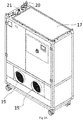
- a portable heat exchanger 5 is shown in more detail.
- the portable heat exchanger 5 is connected to the annular duct 3 by flexible ducts 4a, 4b.
- the portable heat exchanger includes an air inlet grille 17 for receiving warm air, a heat exchanger 18 for cooling the received warm air, and outlets 19 for expelling cooled air.
- the outlets 19 are for connection to the flexible ducts/hoses 4a, 4b, shown in Figure 1B .
- the portable heat exchanger 5 is connectable to a cold water system; for example, a cold water system of a building, via water flow/return connectors 20.
- a condensate pump (not shown) is provided together with a condensate pipe connector 21 for connection to the drainage system of a building; for example, a hospital.
- the portable heat exchanger 5 can be connected to a hospital chiller in order to provide chilled water for the heat exchanger 18.
- a condensate drip tray 22, centrifugal fans 23 and air outlet connection plenums 24 are also shown in Figures 3A and 3B.
- the portable heat exchanger 5 provides cold air for the water conditioning system 12 to ensure that the temperature difference between the water inside the water conditioning system 12 and the air around the heat exchangers 13 is large enough to provide efficient cooling.
- the portable heat exchanger 5 pulls in warm air through the air inlet grill 17 at the top of the unit. It cools the air to 14 ⁇ 2°C and blows the air out into the interface of the unit with the flexible ducts 4a, 4b.
- the flexible ducts 4a, 4b carry the cold air to the interface with the annular duct 3.
- the annular duct 3 in turn transfers this cold air in through the air inlet 6, around the annular duct 3.
- the annular duct 3 in the gap between the medical imaging device and the gantry 1 provides dedicated cold air to the inlet of the water conditioning system and ensures that the temperature difference between the water in the water conditioning system 12 and the air that surrounds the heat exchangers is maintained as required.
- the cold air reaches the plenum 14 on the water conditioning system 12 through the aperture 15 in the gantry segment 1a, where the water conditioning system 12 resides.
- the air then gets pulled through the heat exchangers 13 by the fans 11 and it cools the water inside the heat-exchangers 13 of the water conditioning system 12.
- the warmer air gets blown away from the circumference of the water conditioning system 12 and gantry 1 by the fans 11.
- the warm air will mix again with the air inside of the treatment room and reach the portable heat exchanger 5, passing into the inlet grill of the portable heat exchanger 5 as the cycle continues.
- the plenum 14 of the water conditioning system 12 isolates the heat exchangers 13 from their surroundings. It ensures that the cold air is directed right through to the heat exchangers 13 and also that no warm air from the fans 11 is re-circulated back near the heat exchangers 13. This improvement was found to ensure that the water conditioning system 12 maintains the desired temperature of around 30 ⁇ 5°C regardless of the gantry position; i.e. the angle of rotation of the gantry 1. It was found that re-circulation of the hot air is prevented, so that the efficiency and cooling capacity of the heat exchangers 13 is maintained.
Landscapes
- Health & Medical Sciences (AREA)
- Engineering & Computer Science (AREA)
- Life Sciences & Earth Sciences (AREA)
- Biomedical Technology (AREA)
- Nuclear Medicine, Radiotherapy & Molecular Imaging (AREA)
- Radiology & Medical Imaging (AREA)
- General Health & Medical Sciences (AREA)
- Pathology (AREA)
- Animal Behavior & Ethology (AREA)
- Public Health (AREA)
- Veterinary Medicine (AREA)
- Physics & Mathematics (AREA)
- Medical Informatics (AREA)
- High Energy & Nuclear Physics (AREA)
- Biophysics (AREA)
- Optics & Photonics (AREA)
- Heart & Thoracic Surgery (AREA)
- Molecular Biology (AREA)
- Surgery (AREA)
- Theoretical Computer Science (AREA)
- Pulmonology (AREA)
- Condensed Matter Physics & Semiconductors (AREA)
- General Physics & Mathematics (AREA)
- Thermotherapy And Cooling Therapy Devices (AREA)
- Radiation-Therapy Devices (AREA)
Abstract
Description
- The present invention relates to an image guided radiation therapy (IGRT) apparatus. More particularly the invention provides an IGRT apparatus comprising a cooling system.
- Radiation therapy is a localised treatment designed to treat an identified tissue target (such as a cancerous tumour) and spare the surrounding normal tissue from receiving doses above specified tolerances thereby minimising risk of damage to healthy tissue. Prior to delivery of radiation therapy, an imaging system can be used to provide a three dimensional image of the target from which the target's size and mass can be estimated and an appropriate treatment plan determined.
- Many factors may contribute to differences between the dose distribution determined in the treatment plan and the delivered dose distribution. One such factor is an inconsistency between the patient position at the imaging stage and the patient position in the radiation treatment unit.
- Image guided radiation therapy (IGRT) is known. The method involves the use of an imaging system to view target tissues whilst radiation treatment is being delivered to the target tissue. IGRT incorporates imaging coordinates from the treatment plan to ensure the patient is properly aligned for treatment in the radiation therapy device.
- Various medical imaging technologies are used to identify target tissues in radiation therapy planning and IGRT. These include (without limitation); Computed Tomography (CT), Positron Emission Tomography (PET), ultrasound imaging and Magnetic Resonance Imaging (MRI).
- The Applicant's prior published international patent application no.
WO03/008986 - The use of various devices within close proximity to one another means that the apparatus can suffer from overheating problems. These problems are often solved by the use of complex and sizeable cooling systems, which require large spaces in which to operate. Further problems are also associated with the use of known cooling systems in relation to the cooling of a rotating gantry and devices mounted thereon. For example, known water cooling systems include a reeling system of water pipes that are required to not continuously rotate. There are significant restrictions placed on an IGRT cooling system because the IGRT system is large and housed within a confined space. The present invention seeks to alleviate the problems associated with known cooling systems for IGRT apparatus.
- According to one aspect of the present invention, there is provided an image guided radiation therapy (IGRT) apparatus comprising a medical imaging device and a radiation source, wherein the radiation source is provided on a gantry which surrounds the medical imaging device, the apparatus further comprising ducting for directing cool air from a source of cool air to a gap between the gantry and the medical imaging device.
- In the context of the present invention, it is to understood that "ducting" refers to a passageway or elongate cavity that carries and directs cool air. It is to be understood that the passageway can be enclosed with openings at each of its ends or can be an open structure shaped to direct cool air.
- Preferably, the gantry is rotatable about the medical imaging device. More preferably, the gantry is freely rotatable about the medical imaging device.
- Preferably, the ducting comprises an annular duct for directing cold air into the gap between the gantry and the medical imaging device.
- More preferably, the ducting for directing cool air from a source of cool air to a gap between the gantry and the medical imaging device comprises at least one flexible hose and an annular duct.
- Preferably, the annular duct is provided between the gantry and the medical imaging device turret.
- Preferably, the annular duct is positioned around the medical imaging device.
- Preferably, the gantry is rotatable about the annular duct.
- Preferably, the annular duct comprises an inlet for receiving cool air, preferably wherein the inlet is positioned at, or near, the base of the annular duct.
- It is understood that the "base of the annular duct" refers to the base, i.e. the floor of the treatment room in which the annular duct and the IGRT are housed. This means that cool air enters the annular duct at a position where it can rise, thus aiding movement of air towards the top of the IGRT. This is also advantageous because it means that the lower part of the IGRT, which would likely be positioned within a hole or pit in the treatment room floor, is closest to the entry of cool air into the gantry. Since this lower part of the IGRT is often difficult to cool, such an arrangement aides cooling considerably.
- Preferably, the annular duct comprises a plurality of segments. This allows the annular duct to be installed around the medical imaging device.
- Preferably, the annular duct comprise at least one segment have a substantially L-shaped, curved profile. Optionally, the annular duct comprise at least one segment have a substantially U-shaped, curved profile.
- Preferably, one of the segments is an inlet segment and comprises an inlet for receiving air from a first section of the ducting into the annular duct.
- Preferably, the annular duct comprises an annular outlet for releasing air into the gap between the gantry and the medical imaging device.
- Preferably, the annular duct is shaped to fit around the medical imaging device.
- Preferably, the gantry comprises one or more air directing members for directing air from the ducting in a direction towards the outside of the gantry.
- Preferably, the gantry comprises one or more air directing members for directing air away from a position below the gantry. This is particularly advantageous because it is common for a gantry to sit within a hole in the floor and so, if warmed air is allowed to sit within the hole, i.e. beneath the gantry, this can hinder cooling of the gantry.
- Preferably, the air directing members are configured for directing air towards the outside of the gantry as the gantry rotates about the medical imaging device.
- Preferably, the air directing members are configured for directing air towards the outside of the gantry as the gantry rotates about the annular duct.
- Preferably, the one or more air directing members comprise one or more baffle plates.
- Preferably, the gantry comprises one or more fans for directing air from the ducting to the outside of the gantry.
- Preferably, the gantry comprises a water conditioning system for cooling the components on the gantry.
- Preferably, the water conditioning system is a water cooling system. Further preferably, the water conditioning system is a water cooling and water heating system.
- Preferably, the water conditioning system comprises one or more heat exchangers.
- Preferably, the gantry comprises one or more air directing members for directing air past the one or more heat exchangers.
- Preferably, the gantry comprises one or more air directing members for preventing or reducing the amount of warmed air re-circulating past the one or more heat exchangers.
- Preferably, the one or more air directing members comprise one or more fans and/or one or more baffle plates.
- Preferably, the gantry comprises one or more plenums.
- Within this specification, it will be appreciated that a "plenum" is an enclosed chamber within the gantry or water conditioning system into which air circulating through the gantry is unable to pass.
- Preferably, the gantry comprises one or more plenums for separating the one or more heat exchangers from re-circulating warmed air.
- In this respect, in embodiments comprising one or more plenums, the plenums provide an enclosed space into which warmed air cannot pass. In addition, by reducing the available air flow passages within the gantry, re-circulation of warmed air back into the gantry is significantly reduced because the available air flow passages in the gantry are filled with air moving radially outward from the ducting and across the gantry.
- Preferably, the gantry comprises one or more plenums positioned radially inward of the one or more heat exchangers.
- Preferably, each heat exchanger comprises or is positioned adjacent one or more plenums.
- Preferably, the gantry comprises a plurality of apertures through which air can pass.
- Preferably, the gantry comprises an inlet for the passage of air from the gap between the gantry and the medical imaging device. Preferably, the inlet is oval-shaped or rectangular-shaped, having rounded ends.
- Preferably, the apparatus comprised flexible ducting for connecting the annular duct to a source of cool air. This is advantageous because it allows the air conditioning unit to be positioned in a variety of locations best suited to the available electrical and/or water connections of a room. For example, this is particularly advantageous in embodiments wherein the air conditioning unit is to be connected to the cold water supply of a building.
- Preferably, the source of cool air is a heat exchanger; for example, an air conditioning unit.
- As such, in some embodiments, the apparatus further comprises a source of cool air, such as an heat exchanger; for example, an air conditioning unit.
- Preferably, the heat exchanger is a portable heat exchanger.
- Preferably, the heat exchanger comprises an inlet for receiving warm air, one or more heat exchangers for cooling the received warm air and an outlet for expelling cooled air. Preferably, the outlet is for connection to the ducting.
- Preferably, the heat exchanger is connectable to a cold water system; for example, a cold water system of a building; preferably a hospital. In this way, the heat exchangers can be provided with a particularly convenient supply of cold water for cooling the warm air entering the inlet.
- Preferably, the air conditioning unit comprises a condensate pump.
- Preferably, the air conditioning unit comprises a drain for connection to the drainage system of a building; for example, a hospital.
- Preferably, the gantry comprises a static ring component and a dynamic ring component upon which a radiation source is mounted, the dynamic ring component being rotatable about the ring centre.
- According to another aspect of the present invention, there is provided a gantry for surrounding a medical imaging device, the gantry comprising ducting for directing cool air from a source of cool air to a gap between the gantry and a medical imaging device.
- Within this specification embodiments have been described in a way which enables a clear and concise specification to be written, but it is intended and will be appreciated that embodiments may be variously combined or separated without parting from the invention. For example, it will be appreciated that all preferred features described herein are applicable to all aspects of the invention described herein and vice versa.
- It will be appreciated that reference to "one or more" includes reference to "a plurality".
- An embodiment of the invention will now be described with reference to the accompanying Figures in which:
-
Figures 1A and1B show a perspective view of an image guided radiation therapy (IGRT) apparatus in accordance with the present invention; -
Figure 2 shows a water conditioning system for use in the IGRT apparatus; -
Figures 3A and3B shows the components and a view of the inside of a heat exchanger for use in the IGRT apparatus; -
Figure 4 shows a gantry segment for receiving a water conditioning unit; and -
Figures 5A shows the components of an annular duct of the IGRT apparatus; -
Figure 5B shows an annular duct main segment and 5C shows an annular duct air inlet segment for use in the IGRT apparatus. -
Figures 1A and1B show an image guided radiation therapy (IGRT) apparatus in accordance with the present invention. In use, the radiation therapy apparatus comprises a linear accelerator (LINAC) mounted on thegantry 1 and an MRI scanner (not shown) sits in the aperture of thering gantry 1 sharing the isocentre. A body to be treated is introduced into a treatment space at the isocentre by means of a sliding table (not shown). Thegantry 1 is typically of the order of 2-3 metres in diameter. The IGRT apparatus further comprises a beam emitting module and a beam shaping module (not shown), which are transported around the target by means of thegantry 1. -
Ducting heat exchanger 5 to a gap (not shown) between thegantry 1 and the medical imaging device. - The ducting includes an
annular duct 3 positioned around the medical imaging device for pushing cold air into the gap between thegantry 1 and the medical imaging device and a pair of flexible ducts/hoses annular duct 3 to theportable heat exchanger 5. Thegantry 1 is rotatable about theannular duct 3. Theannular duct 3 is also connected to thecryostat 3 of the MRI device; theconcrete pit 7 in the floor of the treatment room and the RF cage (not shown). - The
annular duct 3 is shown in greater detail with reference toFigure 1B andFigures 5A to 5C . Theannular duct 3 is vacuum-formed out of ABS (acrylonitrile butadiene styrene) and has a thickness of around 4mm. - Referring to
Figure 5A , theannular duct 3 comprises aninlet 6 for receiving cool air in to anair inlet segment 3f of theannular duct 3. Theinlet 6 is positioned at the base of theannular duct 3. This means that cool air enters theannular duct 3 at a position where it can rise, thus aiding general movement of air towards the top of the IGRT device. Referring toFigure 1B , this is also advantageous because it means that the lower part of the IGRT, which is positioned within apit 7 in the treatment room floor, is closest to the entry of cool air into thegantry 1. Theannular duct 3 includes anannular outlet 25, in the form of an open face of the annular duct, for releasing air into the gap between thegantry 1 and the medical imaging device. - Referring to
Figures 5A and5B , theannular duct 3 comprises a plurality ofsegments Figure 5A , one of thesegments 3f comprises theinlet 6. Twotabs 24 are provided on opposing ends of eachsegment tab 24 has have an outward angle of 3 degrees. This enables the tabs to be pushed against each other and create a seal. As shown inFigure 5B , the profile of thesegment 3b of theannular duct 3 is substantially L-shaped with an upstanding U-shaped lip protruding from one wall of thesegment 3b. - The
inlet segment 3f is connected to joiningpiece 8a which, together with joiningpiece 8b provides a rigid support connecting theannular duct 3 with theflexible hoses flexible ducts 4 are each 250mm diameter and have a quick-release connection to the joiningpiece 8b. The joiningpiece 8b allows for a dedicated cold air supply from the portable heat exchanged 5 to theannular duct 3. In the example shown inFigure 5C , theannular duct segment 3f includes anotch 9, which is shaped to fit around the cryostat of the medical imaging device. - Referring to
Figure 4 , each gantry segment 1a of the IGRT apparatus comprises a plurality ofbaffle plates 10 for directing air from theannular ducting 3 in a direction radially outward towards the outside of thegantry 1; for example, as thegantry 1 rotates, in use.Fans 11 are also provided for directing air and, in the embodiment shown, also form part of awater conditioning system 12 for cooling thegantry 1. Thewater conditioning system 12 is connected to a water distribution unit (not shown), which distributes the water around thegantry 1 to cool thegantry 1 and components mounted thereon. Thewater conditioning system 12 provides water cooling of the components of the beam generation module (not shown). Thewater conditioning system 12 is a self-contained, temperature controlled water cooling and heating system, which is designed to provide water that is regulated to 30±5°C. Thewater conditioning system 12 is able to cool water in the system during operation and also heat water in the system before operation so that the apparatus can be provided at the required operating temperature for start-up. - With reference to
Figure 2 , awater conditioning system 12 includes a pair offans 11 which draw air past a pair ofheat exchangers 13. A plenum/chamber 14 is provided and positioned radially inward of thewater conditioning system 12. Theplenums 14 provide an enclosed space into which warmed air cannot pass. Thus, re-circulation of warmed air back into thegantry 1 is significantly reduced because the available air flow passages of thegantry 1 are filled with air moving radially outward from theducting 3 and across thegantry 1. - The
gantry 1 includes a plurality of gantry segments 1a. Awater conditioning system 12 resides in each gantry segment 1a. Each gantry segment 1a includesapertures 15 through which air can pass. With reference toFigure 4 , onesuch aperture 15 forms an inlet for cool air to pass from the space between thegantry 1 and the medical imaging device. Theaperture 15 comprises a cut-out in the gantry segment 1a, which is oval-shaped. In alternative embodiments, theaperture 15 comprises two circular apertures, or a rectangular aperture having rounded ends. Theaperture 15 ensures that thewater conditioning system 12 has the required dedicated flow of cold air, but does not jeopardise the structural integrity of thegantry 1. Thegantry 1 is also provided withmounts 16 to which thewater conditioning system 12 can be attached. As will be appreciated, theannular duct 3 provides cooling for electronics on thegantry 1 and the expelled cold air also cools down the room to some extent. - With reference to
Figure 3A andFigure 3B , aportable heat exchanger 5 is shown in more detail. Theportable heat exchanger 5 is connected to theannular duct 3 byflexible ducts air inlet grille 17 for receiving warm air, aheat exchanger 18 for cooling the received warm air, andoutlets 19 for expelling cooled air. Theoutlets 19 are for connection to the flexible ducts/hoses Figure 1B . - The
portable heat exchanger 5 is connectable to a cold water system; for example, a cold water system of a building, via water flow/return connectors 20. A condensate pump (not shown) is provided together with acondensate pipe connector 21 for connection to the drainage system of a building; for example, a hospital. Theportable heat exchanger 5 can be connected to a hospital chiller in order to provide chilled water for theheat exchanger 18. Also shown inFigures 3A and3B are acondensate drip tray 22,centrifugal fans 23 and airoutlet connection plenums 24. - The
portable heat exchanger 5 provides cold air for thewater conditioning system 12 to ensure that the temperature difference between the water inside thewater conditioning system 12 and the air around theheat exchangers 13 is large enough to provide efficient cooling. - In use, the
portable heat exchanger 5 pulls in warm air through theair inlet grill 17 at the top of the unit. It cools the air to 14 ± 2°C and blows the air out into the interface of the unit with theflexible ducts flexible ducts annular duct 3. Theannular duct 3 in turn transfers this cold air in through theair inlet 6, around theannular duct 3. Theannular duct 3 in the gap between the medical imaging device and thegantry 1 provides dedicated cold air to the inlet of the water conditioning system and ensures that the temperature difference between the water in thewater conditioning system 12 and the air that surrounds the heat exchangers is maintained as required. The cold air reaches theplenum 14 on thewater conditioning system 12 through theaperture 15 in the gantry segment 1a, where thewater conditioning system 12 resides. The air then gets pulled through theheat exchangers 13 by thefans 11 and it cools the water inside the heat-exchangers 13 of thewater conditioning system 12. The warmer air gets blown away from the circumference of thewater conditioning system 12 andgantry 1 by thefans 11. The warm air will mix again with the air inside of the treatment room and reach theportable heat exchanger 5, passing into the inlet grill of theportable heat exchanger 5 as the cycle continues. - With reference to
Figure 2 , theplenum 14 of thewater conditioning system 12 isolates theheat exchangers 13 from their surroundings. It ensures that the cold air is directed right through to theheat exchangers 13 and also that no warm air from thefans 11 is re-circulated back near theheat exchangers 13. This improvement was found to ensure that thewater conditioning system 12 maintains the desired temperature of around 30 ± 5°C regardless of the gantry position; i.e. the angle of rotation of thegantry 1. It was found that re-circulation of the hot air is prevented, so that the efficiency and cooling capacity of theheat exchangers 13 is maintained. - Further embodiments and simple design variations of the embodiments disclosed herein will no doubt occur to the skilled addressee without departing from the true scope of the claims of the invention as defined in the appended claims.
Claims (15)
- An image guided radiation therapy (IGRT) apparatus comprising a medical imaging device and a radiation source, wherein the radiation source is provided on a gantry which surrounds the medical imaging device, the apparatus further comprising ducting for directing cool air from a source of cool air to a gap between the gantry and the medical imaging device.
- An IGRT apparatus according to claim 1 wherein the gantry is rotatable about the medical imaging device; and/or wherein the gantry is freely rotatable about the medical imaging device.
- An IGRT apparatus according to any preceding claim wherein the ducting comprises an annular duct for directing cold air into the gap between the gantry and the medical imaging device; optionally, wherein the ducting for directing cool air from a source of cool air to a gap between the gantry and the medical imaging device comprises at least one flexible hose and an annular duct; optionally, i) wherein the annular duct is provided between the gantry and the medical imaging device turret; and/or ii) wherein the annular duct is positioned around the medical imaging device; and/or iii) wherein the gantry is rotatable about the annular duct, optionally, wherein the annular duct comprises an inlet for receiving cool air; optionally, wherein the inlet is positioned at, or near, the base of the annular duct.
- An IGRT apparatus according to claim 3 wherein the annular duct comprises a plurality of segments; optionally, i) wherein the annular duct comprises at least one segment have a substantially L-shaped, curved profile; or, ii) wherein the annular duct comprise at least one segment have a substantially U-shaped, curved profile; and/or iii) wherein one of the segments is an inlet segment and comprises an inlet for receiving air from a first section of the ducting into the annular duct.
- An IGRT apparatus according to claim 4 wherein the annular duct comprises an annular outlet for releasing air into the gap between the gantry and the medical imaging device; and/or wherein the annular duct is shaped to fit around the medical imaging device.
- An IGRT apparatus according to any preceding claim wherein the gantry comprises one or more air directing members for directing air from the ducting in a direction towards the outside of the gantry.
- An IGRT apparatus according to any preceding claim wherein the gantry comprises one or more air directing members for directing air away from a position below the gantry; optionally, wherein the air directing members are configured for directing air towards the outside of the gantry as the gantry rotates about the medical imaging device; and/or wherein the air directing members are configured for directing air towards the outside of the gantry as the gantry rotates about the annular duct.
- An IGRT apparatus according to claim 7 wherein the one or more air directing members comprise one or more baffle plates.
- An IGRT apparatus according to any preceding claim wherein the gantry comprises one or more fans for directing air from the ducting to the outside of the gantry.
- An IGRT apparatus according to any preceding claim wherein the gantry comprises a water conditioning system for cooling the components on the gantry; optionally, wherein the water conditioning system is a water cooling system; and/or wherein the water conditioning system is a water cooling and a water heating system.
- An IGRT apparatus according to claim 10 wherein the water conditioning system comprises one or more heat exchangers; optionally, wherein the gantry comprises one or more air directing members for directing air past the one or more heat exchangers; optionally, wherein the one or more air directing members comprise one or more fans and/or one or more baffle plates.
- An IGRT apparatus according to any preceding claim wherein the gantry comprises one or more plenums.
- An IGRT apparatus according to any of claims 11 to 12 wherein the gantry comprises one or more plenums for separating the one or more heat exchangers from re-circulating warmed air; optionally, wherein the gantry comprises one or more plenums positioned radially inward of the one or more heat exchangers; optionally, wherein each heat exchanger comprises or is positioned adjacent one or more plenums.
- An IGRT apparatus according to any preceding claim wherein the gantry comprises a plurality of apertures through which air can pass; and/or wherein the gantry comprises an inlet for the passage of air from the gap between the gantry and the medical imaging device; optionally, wherein the inlet is oval-shaped or wherein the inlet is rectangular-shaped having rounded ends, and/or wherein the IGRT apparatus comprises flexible ducting for connecting the annular duct to a source of cool air; optionally, i) further comprising a heat exchanger; optionally, ii) wherein the heat exchanger is a portable heat exchanger; optionally, iii) wherein the heat exchanger comprises an inlet for receiving warm air, one or more heat exchangers for cooling the received warm air and an outlet for expelling cooled air; optionally, iv) wherein the outlet is for connection to the ducting; and/or v) wherein the heat exchanger is connectable to a cold water system.
- An IGRT apparatus according to any preceding claim wherein the gantry comprises a static ring component and a dynamic ring component upon which a radiation source is mounted, the dynamic ring component being rotatable about the ring centre.
Applications Claiming Priority (1)
| Application Number | Priority Date | Filing Date | Title |
|---|---|---|---|
| GB1716297.5A GB2567193A (en) | 2017-10-05 | 2017-10-05 | Image guided radiation therapy apparatus |
Publications (2)
| Publication Number | Publication Date |
|---|---|
| EP3466489A1 true EP3466489A1 (en) | 2019-04-10 |
| EP3466489B1 EP3466489B1 (en) | 2021-06-16 |
Family
ID=60326734
Family Applications (1)
| Application Number | Title | Priority Date | Filing Date |
|---|---|---|---|
| EP18198449.3A Active EP3466489B1 (en) | 2017-10-05 | 2018-10-03 | Image guided radiation therapy apparatus |
Country Status (6)
| Country | Link |
|---|---|
| US (1) | US10772590B2 (en) |
| EP (1) | EP3466489B1 (en) |
| CN (1) | CN109621227B (en) |
| AU (1) | AU2018232945A1 (en) |
| CA (1) | CA3018735A1 (en) |
| GB (1) | GB2567193A (en) |
Cited By (3)
| Publication number | Priority date | Publication date | Assignee | Title |
|---|---|---|---|---|
| CN110448325A (en) * | 2019-09-02 | 2019-11-15 | 明峰医疗系统股份有限公司 | A kind of PET system air-cooled radiating device |
| WO2020208207A1 (en) * | 2019-04-12 | 2020-10-15 | Elekta Limited | Radiotherapy apparatus |
| WO2021236172A1 (en) * | 2020-05-19 | 2021-11-25 | Siemens Medical Solutions Usa, Inc. | Air cooled pet scanner gantry |
Families Citing this family (7)
| Publication number | Priority date | Publication date | Assignee | Title |
|---|---|---|---|---|
| EP3698326A4 (en) | 2017-10-19 | 2021-08-11 | Spectrum Dynamics Medical Limited | CALIBRATION AND QUALITY CONTROL OF A NUCLEAR MEDICAL RADIO IMAGING SYSTEM |
| EP3698154B1 (en) * | 2017-10-19 | 2025-07-16 | Spectrum Dynamics Medical Limited | Cooling of a nuclear medicine tomography system |
| GB2576342A (en) * | 2018-08-15 | 2020-02-19 | Elekta ltd | Adjustable support |
| DE102019204501A1 (en) * | 2019-03-29 | 2020-10-01 | Siemens Healthcare Gmbh | Cooling system for a computed tomography device and method for cooling a computed tomography device |
| KR102481736B1 (en) * | 2020-09-22 | 2022-12-27 | 주식회사 수퍼제닉스 | A superconducting magnet cooling system for magnetic resonance imaging device |
| CN112710123B (en) * | 2020-12-29 | 2022-03-29 | 陕西华明普泰医疗设备有限公司 | Water circulation system of drum-type medical accelerator |
| US11940512B2 (en) * | 2022-08-18 | 2024-03-26 | GE Precision Healthcare LLC | Systems and methods for body coil air cooling |
Citations (6)
| Publication number | Priority date | Publication date | Assignee | Title |
|---|---|---|---|---|
| US20040202287A1 (en) * | 2003-03-19 | 2004-10-14 | Hans-Jurgen Muller | Cooling system and method to cool a gantry |
| US20040228450A1 (en) * | 2003-02-05 | 2004-11-18 | Han-Juergen Mueller | Cooling system and method to cool a gantry |
| US20060215808A1 (en) * | 2005-03-23 | 2006-09-28 | General Electric Company | System and method for cooling components rotatable about an axis |
| EP2343103A1 (en) * | 2010-01-12 | 2011-07-13 | Koninklijke Philips Electronics N.V. | Therapeutic apparatus |
| DE102011081257A1 (en) * | 2011-08-19 | 2013-02-21 | Siemens Aktiengesellschaft | Radiation therapy device for treatment of tumor diseases, has imaging unit comprising holder for holding detector provided for image acquisition, where holder is rotatably mounted in radiation plane for rotation of detector |
| WO2015197475A1 (en) * | 2014-06-27 | 2015-12-30 | Koninklijke Philips N.V. | Charged particle beam therapy and magnetic resonance imaging |
Family Cites Families (13)
| Publication number | Priority date | Publication date | Assignee | Title |
|---|---|---|---|---|
| US5299249A (en) * | 1992-11-27 | 1994-03-29 | Picker International, Inc. | Heat transfer techniques for moving thermal energy from high power X-ray tubes on rotating CT gantries to a remote location |
| DE4427106A1 (en) * | 1994-07-30 | 1996-02-01 | Otto Werner Woelky | Process for control of tumours and skin cancer |
| US20050135560A1 (en) * | 2003-12-17 | 2005-06-23 | Ehud Dafni | Portable computed tomography scanner and methods thereof |
| DE102004055752B4 (en) * | 2004-11-18 | 2007-12-13 | Siemens Ag | CT Scanner |
| CN1778274A (en) * | 2004-11-22 | 2006-05-31 | 深圳市益普生医疗设备发展有限公司 | X ray therapeutical system |
| US8232535B2 (en) * | 2005-05-10 | 2012-07-31 | Tomotherapy Incorporated | System and method of treating a patient with radiation therapy |
| DE102007037313B4 (en) * | 2007-08-08 | 2009-11-12 | Siemens Ag | Computed tomography device with a gantry for holding components of a recording system rotatably arranged about a system axis |
| WO2011008969A1 (en) * | 2009-07-15 | 2011-01-20 | Viewray Incorporated | Method and apparatus for shielding a linear accelerator and a magnetic resonance imaging device from each other |
| US8963108B2 (en) * | 2012-10-26 | 2015-02-24 | ProNova Solutions, LLC | Proton treatment gantry system |
| DE102014205393B4 (en) * | 2014-03-24 | 2018-01-25 | Siemens Healthcare Gmbh | CT system |
| CN105266836A (en) * | 2015-09-09 | 2016-01-27 | 上海联影医疗科技有限公司 | Cooling assembly of medical device and medical device |
| US10390778B2 (en) * | 2015-10-19 | 2019-08-27 | Canon Medical Systems Corporation | Gantry |
| US10054698B2 (en) * | 2016-08-31 | 2018-08-21 | General Electric Company | Temperature stabilization for detector heads |
-
2017
- 2017-10-05 GB GB1716297.5A patent/GB2567193A/en not_active Withdrawn
-
2018
- 2018-09-19 AU AU2018232945A patent/AU2018232945A1/en not_active Abandoned
- 2018-09-26 CA CA3018735A patent/CA3018735A1/en active Pending
- 2018-09-28 CN CN201811136421.1A patent/CN109621227B/en active Active
- 2018-10-03 EP EP18198449.3A patent/EP3466489B1/en active Active
- 2018-10-03 US US16/150,663 patent/US10772590B2/en active Active
Patent Citations (6)
| Publication number | Priority date | Publication date | Assignee | Title |
|---|---|---|---|---|
| US20040228450A1 (en) * | 2003-02-05 | 2004-11-18 | Han-Juergen Mueller | Cooling system and method to cool a gantry |
| US20040202287A1 (en) * | 2003-03-19 | 2004-10-14 | Hans-Jurgen Muller | Cooling system and method to cool a gantry |
| US20060215808A1 (en) * | 2005-03-23 | 2006-09-28 | General Electric Company | System and method for cooling components rotatable about an axis |
| EP2343103A1 (en) * | 2010-01-12 | 2011-07-13 | Koninklijke Philips Electronics N.V. | Therapeutic apparatus |
| DE102011081257A1 (en) * | 2011-08-19 | 2013-02-21 | Siemens Aktiengesellschaft | Radiation therapy device for treatment of tumor diseases, has imaging unit comprising holder for holding detector provided for image acquisition, where holder is rotatably mounted in radiation plane for rotation of detector |
| WO2015197475A1 (en) * | 2014-06-27 | 2015-12-30 | Koninklijke Philips N.V. | Charged particle beam therapy and magnetic resonance imaging |
Cited By (5)
| Publication number | Priority date | Publication date | Assignee | Title |
|---|---|---|---|---|
| WO2020208207A1 (en) * | 2019-04-12 | 2020-10-15 | Elekta Limited | Radiotherapy apparatus |
| US11931603B2 (en) | 2019-04-12 | 2024-03-19 | Elekta Limited | Radiotherapy apparatus |
| CN110448325A (en) * | 2019-09-02 | 2019-11-15 | 明峰医疗系统股份有限公司 | A kind of PET system air-cooled radiating device |
| WO2021236172A1 (en) * | 2020-05-19 | 2021-11-25 | Siemens Medical Solutions Usa, Inc. | Air cooled pet scanner gantry |
| US11998377B2 (en) | 2020-05-19 | 2024-06-04 | Siemens Medical Solutions Usa, Inc. | Air cooled PET scanner gantry |
Also Published As
| Publication number | Publication date |
|---|---|
| CN109621227B (en) | 2021-12-28 |
| CN109621227A (en) | 2019-04-16 |
| CA3018735A1 (en) | 2019-04-05 |
| AU2018232945A1 (en) | 2019-05-02 |
| GB201716297D0 (en) | 2017-11-22 |
| US20190105005A1 (en) | 2019-04-11 |
| EP3466489B1 (en) | 2021-06-16 |
| US10772590B2 (en) | 2020-09-15 |
| GB2567193A (en) | 2019-04-10 |
Similar Documents
| Publication | Publication Date | Title |
|---|---|---|
| EP3466489B1 (en) | Image guided radiation therapy apparatus | |
| US12285635B2 (en) | Single-pass imaging and radiation treatment delivery via an extended rotation gantry | |
| US12121299B2 (en) | Thermal cooling ring for radiation therapy system | |
| CN110234275B (en) | System for emission-guided high-energy photon transport | |
| CN104939856B (en) | Computed tomography imaging system | |
| JP6548665B2 (en) | Methods and systems for stereotactic intensity modulated rotational radiotherapy | |
| Abdullah et al. | Robot-assisted radiofrequency ablation of primary and secondary liver tumours: early experience | |
| WO1998010696A1 (en) | Megavoltage radiation therapy machine combined with diagnostic imaging devices | |
| WO2009069024A1 (en) | Gantry cooling | |
| CN116459458B (en) | A radiotherapy device | |
| US9222687B2 (en) | Active chilled beam with sterilization means | |
| TW201934158A (en) | Particle radiation therapy apparatus | |
| JP2012108110A (en) | Medical imaging system | |
| Patel et al. | Evolution of image guidance and adaptive radiation therapy for localized prostate cancer | |
| US11627926B2 (en) | Patient comfort in nuclear imaging system | |
| EP3952985B1 (en) | Radiotherapy apparatus | |
| CN219630465U (en) | A radiotherapy device | |
| JP2016106987A (en) | Operation room air-conditioning system | |
| US20200297890A1 (en) | Method of and unit for air treatment | |
| Chun et al. | A case report of salvage radiotherapy for a patient with recurrent gastric cancer and multiple comorbidities using real-time MRI-guided adaptive treatment system | |
| US11490866B2 (en) | Methods and systems for cooling of an imaging system | |
| US20150246245A1 (en) | Hadron therapy installation comprising an imaging device | |
| GB2590648A (en) | Radiotherapy apparatus | |
| Hong | Breast and Chest Wall | |
| Hurley | High Dose Rate Interstitial Brachytherapy of the Prostate. |
Legal Events
| Date | Code | Title | Description |
|---|---|---|---|
| PUAI | Public reference made under article 153(3) epc to a published international application that has entered the european phase |
Free format text: ORIGINAL CODE: 0009012 |
|
| STAA | Information on the status of an ep patent application or granted ep patent |
Free format text: STATUS: THE APPLICATION HAS BEEN PUBLISHED |
|
| AK | Designated contracting states |
Kind code of ref document: A1 Designated state(s): AL AT BE BG CH CY CZ DE DK EE ES FI FR GB GR HR HU IE IS IT LI LT LU LV MC MK MT NL NO PL PT RO RS SE SI SK SM TR |
|
| AX | Request for extension of the european patent |
Extension state: BA ME |
|
| STAA | Information on the status of an ep patent application or granted ep patent |
Free format text: STATUS: REQUEST FOR EXAMINATION WAS MADE |
|
| 17P | Request for examination filed |
Effective date: 20190930 |
|
| RBV | Designated contracting states (corrected) |
Designated state(s): AL AT BE BG CH CY CZ DE DK EE ES FI FR GB GR HR HU IE IS IT LI LT LU LV MC MK MT NL NO PL PT RO RS SE SI SK SM TR |
|
| GRAP | Despatch of communication of intention to grant a patent |
Free format text: ORIGINAL CODE: EPIDOSNIGR1 |
|
| STAA | Information on the status of an ep patent application or granted ep patent |
Free format text: STATUS: GRANT OF PATENT IS INTENDED |
|
| INTG | Intention to grant announced |
Effective date: 20210112 |
|
| RAP1 | Party data changed (applicant data changed or rights of an application transferred) |
Owner name: ELEKTA LIMITED |
|
| GRAS | Grant fee paid |
Free format text: ORIGINAL CODE: EPIDOSNIGR3 |
|
| GRAA | (expected) grant |
Free format text: ORIGINAL CODE: 0009210 |
|
| STAA | Information on the status of an ep patent application or granted ep patent |
Free format text: STATUS: THE PATENT HAS BEEN GRANTED |
|
| AK | Designated contracting states |
Kind code of ref document: B1 Designated state(s): AL AT BE BG CH CY CZ DE DK EE ES FI FR GB GR HR HU IE IS IT LI LT LU LV MC MK MT NL NO PL PT RO RS SE SI SK SM TR |
|
| REG | Reference to a national code |
Ref country code: GB Ref legal event code: FG4D |
|
| REG | Reference to a national code |
Ref country code: CH Ref legal event code: EP |
|
| REG | Reference to a national code |
Ref country code: DE Ref legal event code: R096 Ref document number: 602018018590 Country of ref document: DE |
|
| REG | Reference to a national code |
Ref country code: AT Ref legal event code: REF Ref document number: 1401818 Country of ref document: AT Kind code of ref document: T Effective date: 20210715 |
|
| REG | Reference to a national code |
Ref country code: IE Ref legal event code: FG4D |
|
| REG | Reference to a national code |
Ref country code: LT Ref legal event code: MG9D |
|
| PG25 | Lapsed in a contracting state [announced via postgrant information from national office to epo] |
Ref country code: BG Free format text: LAPSE BECAUSE OF FAILURE TO SUBMIT A TRANSLATION OF THE DESCRIPTION OR TO PAY THE FEE WITHIN THE PRESCRIBED TIME-LIMIT Effective date: 20210916 Ref country code: FI Free format text: LAPSE BECAUSE OF FAILURE TO SUBMIT A TRANSLATION OF THE DESCRIPTION OR TO PAY THE FEE WITHIN THE PRESCRIBED TIME-LIMIT Effective date: 20210616 Ref country code: HR Free format text: LAPSE BECAUSE OF FAILURE TO SUBMIT A TRANSLATION OF THE DESCRIPTION OR TO PAY THE FEE WITHIN THE PRESCRIBED TIME-LIMIT Effective date: 20210616 Ref country code: LT Free format text: LAPSE BECAUSE OF FAILURE TO SUBMIT A TRANSLATION OF THE DESCRIPTION OR TO PAY THE FEE WITHIN THE PRESCRIBED TIME-LIMIT Effective date: 20210616 |
|
| REG | Reference to a national code |
Ref country code: AT Ref legal event code: MK05 Ref document number: 1401818 Country of ref document: AT Kind code of ref document: T Effective date: 20210616 |
|
| REG | Reference to a national code |
Ref country code: NL Ref legal event code: MP Effective date: 20210616 |
|
| PG25 | Lapsed in a contracting state [announced via postgrant information from national office to epo] |
Ref country code: GR Free format text: LAPSE BECAUSE OF FAILURE TO SUBMIT A TRANSLATION OF THE DESCRIPTION OR TO PAY THE FEE WITHIN THE PRESCRIBED TIME-LIMIT Effective date: 20210917 Ref country code: NO Free format text: LAPSE BECAUSE OF FAILURE TO SUBMIT A TRANSLATION OF THE DESCRIPTION OR TO PAY THE FEE WITHIN THE PRESCRIBED TIME-LIMIT Effective date: 20210916 Ref country code: LV Free format text: LAPSE BECAUSE OF FAILURE TO SUBMIT A TRANSLATION OF THE DESCRIPTION OR TO PAY THE FEE WITHIN THE PRESCRIBED TIME-LIMIT Effective date: 20210616 Ref country code: SE Free format text: LAPSE BECAUSE OF FAILURE TO SUBMIT A TRANSLATION OF THE DESCRIPTION OR TO PAY THE FEE WITHIN THE PRESCRIBED TIME-LIMIT Effective date: 20210616 Ref country code: RS Free format text: LAPSE BECAUSE OF FAILURE TO SUBMIT A TRANSLATION OF THE DESCRIPTION OR TO PAY THE FEE WITHIN THE PRESCRIBED TIME-LIMIT Effective date: 20210616 |
|
| PG25 | Lapsed in a contracting state [announced via postgrant information from national office to epo] |
Ref country code: SK Free format text: LAPSE BECAUSE OF FAILURE TO SUBMIT A TRANSLATION OF THE DESCRIPTION OR TO PAY THE FEE WITHIN THE PRESCRIBED TIME-LIMIT Effective date: 20210616 Ref country code: SM Free format text: LAPSE BECAUSE OF FAILURE TO SUBMIT A TRANSLATION OF THE DESCRIPTION OR TO PAY THE FEE WITHIN THE PRESCRIBED TIME-LIMIT Effective date: 20210616 Ref country code: EE Free format text: LAPSE BECAUSE OF FAILURE TO SUBMIT A TRANSLATION OF THE DESCRIPTION OR TO PAY THE FEE WITHIN THE PRESCRIBED TIME-LIMIT Effective date: 20210616 Ref country code: ES Free format text: LAPSE BECAUSE OF FAILURE TO SUBMIT A TRANSLATION OF THE DESCRIPTION OR TO PAY THE FEE WITHIN THE PRESCRIBED TIME-LIMIT Effective date: 20210616 Ref country code: CZ Free format text: LAPSE BECAUSE OF FAILURE TO SUBMIT A TRANSLATION OF THE DESCRIPTION OR TO PAY THE FEE WITHIN THE PRESCRIBED TIME-LIMIT Effective date: 20210616 Ref country code: AT Free format text: LAPSE BECAUSE OF FAILURE TO SUBMIT A TRANSLATION OF THE DESCRIPTION OR TO PAY THE FEE WITHIN THE PRESCRIBED TIME-LIMIT Effective date: 20210616 Ref country code: NL Free format text: LAPSE BECAUSE OF FAILURE TO SUBMIT A TRANSLATION OF THE DESCRIPTION OR TO PAY THE FEE WITHIN THE PRESCRIBED TIME-LIMIT Effective date: 20210616 Ref country code: PT Free format text: LAPSE BECAUSE OF FAILURE TO SUBMIT A TRANSLATION OF THE DESCRIPTION OR TO PAY THE FEE WITHIN THE PRESCRIBED TIME-LIMIT Effective date: 20211018 Ref country code: RO Free format text: LAPSE BECAUSE OF FAILURE TO SUBMIT A TRANSLATION OF THE DESCRIPTION OR TO PAY THE FEE WITHIN THE PRESCRIBED TIME-LIMIT Effective date: 20210616 |
|
| PG25 | Lapsed in a contracting state [announced via postgrant information from national office to epo] |
Ref country code: PL Free format text: LAPSE BECAUSE OF FAILURE TO SUBMIT A TRANSLATION OF THE DESCRIPTION OR TO PAY THE FEE WITHIN THE PRESCRIBED TIME-LIMIT Effective date: 20210616 |
|
| REG | Reference to a national code |
Ref country code: DE Ref legal event code: R097 Ref document number: 602018018590 Country of ref document: DE |
|
| PLBE | No opposition filed within time limit |
Free format text: ORIGINAL CODE: 0009261 |
|
| STAA | Information on the status of an ep patent application or granted ep patent |
Free format text: STATUS: NO OPPOSITION FILED WITHIN TIME LIMIT |
|
| PG25 | Lapsed in a contracting state [announced via postgrant information from national office to epo] |
Ref country code: DK Free format text: LAPSE BECAUSE OF FAILURE TO SUBMIT A TRANSLATION OF THE DESCRIPTION OR TO PAY THE FEE WITHIN THE PRESCRIBED TIME-LIMIT Effective date: 20210616 |
|
| 26N | No opposition filed |
Effective date: 20220317 |
|
| PG25 | Lapsed in a contracting state [announced via postgrant information from national office to epo] |
Ref country code: AL Free format text: LAPSE BECAUSE OF FAILURE TO SUBMIT A TRANSLATION OF THE DESCRIPTION OR TO PAY THE FEE WITHIN THE PRESCRIBED TIME-LIMIT Effective date: 20210616 |
|
| REG | Reference to a national code |
Ref country code: CH Ref legal event code: PL |
|
| REG | Reference to a national code |
Ref country code: BE Ref legal event code: MM Effective date: 20211031 |
|
| PG25 | Lapsed in a contracting state [announced via postgrant information from national office to epo] |
Ref country code: MC Free format text: LAPSE BECAUSE OF FAILURE TO SUBMIT A TRANSLATION OF THE DESCRIPTION OR TO PAY THE FEE WITHIN THE PRESCRIBED TIME-LIMIT Effective date: 20210616 |
|
| PG25 | Lapsed in a contracting state [announced via postgrant information from national office to epo] |
Ref country code: LU Free format text: LAPSE BECAUSE OF NON-PAYMENT OF DUE FEES Effective date: 20211003 Ref country code: IT Free format text: LAPSE BECAUSE OF FAILURE TO SUBMIT A TRANSLATION OF THE DESCRIPTION OR TO PAY THE FEE WITHIN THE PRESCRIBED TIME-LIMIT Effective date: 20210616 Ref country code: BE Free format text: LAPSE BECAUSE OF NON-PAYMENT OF DUE FEES Effective date: 20211031 |
|
| PG25 | Lapsed in a contracting state [announced via postgrant information from national office to epo] |
Ref country code: LI Free format text: LAPSE BECAUSE OF NON-PAYMENT OF DUE FEES Effective date: 20211031 Ref country code: CH Free format text: LAPSE BECAUSE OF NON-PAYMENT OF DUE FEES Effective date: 20211031 |
|
| PG25 | Lapsed in a contracting state [announced via postgrant information from national office to epo] |
Ref country code: IE Free format text: LAPSE BECAUSE OF NON-PAYMENT OF DUE FEES Effective date: 20211003 |
|
| PG25 | Lapsed in a contracting state [announced via postgrant information from national office to epo] |
Ref country code: CY Free format text: LAPSE BECAUSE OF FAILURE TO SUBMIT A TRANSLATION OF THE DESCRIPTION OR TO PAY THE FEE WITHIN THE PRESCRIBED TIME-LIMIT Effective date: 20210616 |
|
| P01 | Opt-out of the competence of the unified patent court (upc) registered |
Effective date: 20230529 |
|
| PG25 | Lapsed in a contracting state [announced via postgrant information from national office to epo] |
Ref country code: HU Free format text: LAPSE BECAUSE OF FAILURE TO SUBMIT A TRANSLATION OF THE DESCRIPTION OR TO PAY THE FEE WITHIN THE PRESCRIBED TIME-LIMIT; INVALID AB INITIO Effective date: 20181003 |
|
| PG25 | Lapsed in a contracting state [announced via postgrant information from national office to epo] |
Ref country code: MK Free format text: LAPSE BECAUSE OF FAILURE TO SUBMIT A TRANSLATION OF THE DESCRIPTION OR TO PAY THE FEE WITHIN THE PRESCRIBED TIME-LIMIT Effective date: 20210616 |
|
| PG25 | Lapsed in a contracting state [announced via postgrant information from national office to epo] |
Ref country code: TR Free format text: LAPSE BECAUSE OF FAILURE TO SUBMIT A TRANSLATION OF THE DESCRIPTION OR TO PAY THE FEE WITHIN THE PRESCRIBED TIME-LIMIT Effective date: 20210616 |
|
| PG25 | Lapsed in a contracting state [announced via postgrant information from national office to epo] |
Ref country code: MT Free format text: LAPSE BECAUSE OF FAILURE TO SUBMIT A TRANSLATION OF THE DESCRIPTION OR TO PAY THE FEE WITHIN THE PRESCRIBED TIME-LIMIT Effective date: 20210616 |
|
| PGFP | Annual fee paid to national office [announced via postgrant information from national office to epo] |
Ref country code: GB Payment date: 20250904 Year of fee payment: 8 |
|
| PGFP | Annual fee paid to national office [announced via postgrant information from national office to epo] |
Ref country code: FR Payment date: 20250908 Year of fee payment: 8 |
|
| PGFP | Annual fee paid to national office [announced via postgrant information from national office to epo] |
Ref country code: DE Payment date: 20250902 Year of fee payment: 8 |