EP3466318A1 - Dental caries diagnosis device - Google Patents
Dental caries diagnosis device Download PDFInfo
- Publication number
- EP3466318A1 EP3466318A1 EP17810266.1A EP17810266A EP3466318A1 EP 3466318 A1 EP3466318 A1 EP 3466318A1 EP 17810266 A EP17810266 A EP 17810266A EP 3466318 A1 EP3466318 A1 EP 3466318A1
- Authority
- EP
- European Patent Office
- Prior art keywords
- light
- tooth
- dental caries
- diagnosis device
- examination
- Prior art date
- Legal status (The legal status is an assumption and is not a legal conclusion. Google has not performed a legal analysis and makes no representation as to the accuracy of the status listed.)
- Granted
Links
Images


Classifications
-
- A—HUMAN NECESSITIES
- A61—MEDICAL OR VETERINARY SCIENCE; HYGIENE
- A61B—DIAGNOSIS; SURGERY; IDENTIFICATION
- A61B1/00—Instruments for performing medical examinations of the interior of cavities or tubes of the body by visual or photographical inspection, e.g. endoscopes; Illuminating arrangements therefor
- A61B1/24—Instruments for performing medical examinations of the interior of cavities or tubes of the body by visual or photographical inspection, e.g. endoscopes; Illuminating arrangements therefor for the mouth, i.e. stomatoscopes, e.g. with tongue depressors; Instruments for opening or keeping open the mouth
-
- A—HUMAN NECESSITIES
- A61—MEDICAL OR VETERINARY SCIENCE; HYGIENE
- A61B—DIAGNOSIS; SURGERY; IDENTIFICATION
- A61B1/00—Instruments for performing medical examinations of the interior of cavities or tubes of the body by visual or photographical inspection, e.g. endoscopes; Illuminating arrangements therefor
- A61B1/00112—Connection or coupling means
- A61B1/00121—Connectors, fasteners and adapters, e.g. on the endoscope handle
- A61B1/00128—Connectors, fasteners and adapters, e.g. on the endoscope handle mechanical, e.g. for tubes or pipes
-
- A—HUMAN NECESSITIES
- A61—MEDICAL OR VETERINARY SCIENCE; HYGIENE
- A61B—DIAGNOSIS; SURGERY; IDENTIFICATION
- A61B1/00—Instruments for performing medical examinations of the interior of cavities or tubes of the body by visual or photographical inspection, e.g. endoscopes; Illuminating arrangements therefor
- A61B1/00163—Optical arrangements
- A61B1/00186—Optical arrangements with imaging filters
-
- A—HUMAN NECESSITIES
- A61—MEDICAL OR VETERINARY SCIENCE; HYGIENE
- A61B—DIAGNOSIS; SURGERY; IDENTIFICATION
- A61B1/00—Instruments for performing medical examinations of the interior of cavities or tubes of the body by visual or photographical inspection, e.g. endoscopes; Illuminating arrangements therefor
- A61B1/06—Instruments for performing medical examinations of the interior of cavities or tubes of the body by visual or photographical inspection, e.g. endoscopes; Illuminating arrangements therefor with illuminating arrangements
- A61B1/07—Instruments for performing medical examinations of the interior of cavities or tubes of the body by visual or photographical inspection, e.g. endoscopes; Illuminating arrangements therefor with illuminating arrangements using light-conductive means, e.g. optical fibres
-
- A—HUMAN NECESSITIES
- A61—MEDICAL OR VETERINARY SCIENCE; HYGIENE
- A61B—DIAGNOSIS; SURGERY; IDENTIFICATION
- A61B5/00—Measuring for diagnostic purposes; Identification of persons
- A61B5/0059—Measuring for diagnostic purposes; Identification of persons using light, e.g. diagnosis by transillumination, diascopy, fluorescence
-
- A—HUMAN NECESSITIES
- A61—MEDICAL OR VETERINARY SCIENCE; HYGIENE
- A61B—DIAGNOSIS; SURGERY; IDENTIFICATION
- A61B5/00—Measuring for diagnostic purposes; Identification of persons
- A61B5/0059—Measuring for diagnostic purposes; Identification of persons using light, e.g. diagnosis by transillumination, diascopy, fluorescence
- A61B5/0082—Measuring for diagnostic purposes; Identification of persons using light, e.g. diagnosis by transillumination, diascopy, fluorescence adapted for particular medical purposes
- A61B5/0088—Measuring for diagnostic purposes; Identification of persons using light, e.g. diagnosis by transillumination, diascopy, fluorescence adapted for particular medical purposes for oral or dental tissue
-
- A—HUMAN NECESSITIES
- A61—MEDICAL OR VETERINARY SCIENCE; HYGIENE
- A61B—DIAGNOSIS; SURGERY; IDENTIFICATION
- A61B5/00—Measuring for diagnostic purposes; Identification of persons
- A61B5/72—Signal processing specially adapted for physiological signals or for diagnostic purposes
- A61B5/7203—Signal processing specially adapted for physiological signals or for diagnostic purposes for noise prevention, reduction or removal
-
- A—HUMAN NECESSITIES
- A61—MEDICAL OR VETERINARY SCIENCE; HYGIENE
- A61C—DENTISTRY; APPARATUS OR METHODS FOR ORAL OR DENTAL HYGIENE
- A61C1/00—Dental machines for boring or cutting ; General features of dental machines or apparatus, e.g. hand-piece design
- A61C1/08—Machine parts specially adapted for dentistry
- A61C1/081—Pain-alleviating features
-
- A—HUMAN NECESSITIES
- A61—MEDICAL OR VETERINARY SCIENCE; HYGIENE
- A61C—DENTISTRY; APPARATUS OR METHODS FOR ORAL OR DENTAL HYGIENE
- A61C19/00—Dental auxiliary appliances
- A61C19/04—Measuring instruments specially adapted for dentistry
Definitions
- the present invention relates to a dental caries diagnosis device.
- Non-Patent Document 1 discloses a dental caries detection image examination device using laser light.
- the dental caries detection image examination device in Non-Patent Document 1 irradiates a tooth with the laser light, receives the laser light reflected by the tooth, and detects a dental caries from an intensity of the received laser light.
- Such a dental caries detection image examination device has a structure in which a tooth is surrounded by a laser light irradiation unit using a clip and a noise component due to external light at the time of examining is prevented from entering a light receiving unit.
- Non-Patent Document 1 when a dental caries detection image examination device such as that described in Non-Patent Document 1 is used, a laser light irradiation unit is fixed to the gum in the mouth. Thus, a testee whose gum is in contact with the laser light irradiation unit during the examination is likely to feel uncomfortable.
- the present invention was made in view of the above-described problems, and an objective of the present invention is to provide a dental caries diagnosis device that does not cause a testee discomfort.
- a dental caries diagnosis device is a dental caries diagnosis device which includes a light source which is configured to emit examination light and a light receiving unit which is configured to receive the examination light with which a tooth has been irradiated including: a head portion which is inserted into a mouth without coming in contact with a tooth or a gum and which projects the examination light toward a tooth; and a filter which is disposed in front of the light receiving unit and which is configured to remove a noise component from the received light, wherein the light receiving unit is configured to receive the examination light which has been transmitted through the tooth.
- the light source may be a light emitting diode.
- the dental caries diagnosis device may include: a prism or a mirror which is configured to refract the examination light with which the tooth has been irradiated toward the light receiving unit.
- the dental caries diagnosis device may include: a light amount adjustment unit which is configured to adjust the amount of the examination light.
- the head portion may include: side wall portions which have a tooth accommodation space and are disposed to face each other so that the side wall portions surround the accommodation space; and a light irradiation unit which is configured to irradiate the examination light from the side wall portions toward a tooth.
- a head portion is inserted into a mouth without coming in contact with a testee's gingiva (gum). For this reason, the testee does not feel uncomfortable.
- a testee's gingiva gingiva
- external light enters the inside of the head portion through a gap between the head portion and the gum and light received by a light receiving unit includes a noise component such as the external light in addition to examination light.
- a filter is provided in front of the light receiving unit in the present invention.
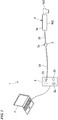
- Fig. 1 is a device constitution diagram of a dental caries diagnosis device 1 according to this embodiment.
- the dental caries diagnosis device 1 includes a main body portion 2, a shutter unit 3, and a handpiece 4, the main body portion 2 and the shutter unit 3 are connected to each other through a cable C1, and the shutter unit 3 and the handpiece 4 are connected to each other through a cable C2.
- the main body portion 2 is a device configured to supply light to the handpiece 4 and transmit and receive signals to and from a computer P and receives supplied electric power when connected to an electric power strip or the like.
- the main body portion 2 includes an electric power switch 2a, a light amount adjustment unit 2b, and a light source 2c.
- the electric power switch 2a is a switch configured to switch between supply start and supply stop of a power supply.
- the light amount adjustment unit 2b is a knob configured to adjust an amount of light of a light irradiation unit 4b which will be described later in the handpiece 4 and can adjust an amount of light of the light source stepwise or steplessly.
- the main body portion 2 is connected to the shutter unit 3 through the cable C1 having an optical fiber light guide connected to the light source installed therein.
- the main body portion 2 is connected to the computer P through a USB cable.
- the computer P includes a monitor which displays a video from a camera 4f which will be described later.
- the light source 2c is a light emitting diode (LED) with a central wavelength of 780 nm configured to emit examination light R and can an amount of light thereof can be adjusted through adjustment of the light amount adjustment unit 2b.
- LED light emitting diode
- the shutter unit 3 is connected to the main body portion 2 via the cable C1 and is connected to the handpiece 4 via the cable C2 having the optical fiber light guide installed therein.
- the shutter unit 3 is an apparatus which includes a shutter switch 3a and performs a shutter operation of the camera 4f which will be described later in the handpiece 4. An inspector can acquire a still image or a moving image through the camera 4f by pressing down the shutter switch 3a.
- Fig. 2A is a side cross-sectional view of the handpiece 4 in the dental caries diagnosis device 1 according to this embodiment.
- Fig. 2B is a front view of a head portion 4A in the handpiece 4 of the dental caries diagnosis device 1 according to this embodiment.
- the handpiece 4 includes a casing 4a, the light irradiation unit 4b, a prism 4c, a lens 4d, a cut filter 4e, and the camera 4f (light receiving unit).
- the casing 4a is an elongated member and includes a head-side casing 4a1 and a grasp portion 4a2 which is shown in Fig. 1 .
- the casing 4a has a hollow or translucent member formed therein through which the examination light R irradiated from the light irradiation unit 4b can pass.
- the head-side casing 4a1 is a resin part inserted into a testee's mouth and has the light irradiation unit 4b and the prism 4c embedded therein. As shown in Fig. 2 , the head-side casing 4a1 has an accommodation space formed to accommodate a tooth between two side wall portions 4a3 erected in parallel at intervals from a distal end of a substantially tubular member through the two side wall portions 4a3. The width of the two side wall portions 4a3 is set wider than an average value of widths of adult molar teeth.
- a part of the side wall portions 4a3 is formed of a translucent member and the light irradiation unit 4b is embedded in a translucent portion of the side wall portions 4a3.
- Such a head-side casing 4a1 is inserted into the testee's mouth such that a tooth is sandwiched between the two side wall portions 4a3.
- the head-side casing 4a1 can be detached from the grasp portion 4a2.
- the grasp portion 4a2 is a portion by which the inspector grasps the handpiece 4 in a range not including the head-side casing 4a1 and has the head-side casing 4a1 attached thereto.
- the lens 4d, the cut filter 4e, and the camera 4f are provided inside the grasp portion 4a2.
- the light irradiation unit 4b is embedded in each of the two side wall portions 4a3 in the head-side casing 4a1 and irradiates examination light R from the sides of a tooth root portion inserted into a concave portion.
- the light irradiation units 4b are connected to the light source of the main body portion 2 via the cables C1 and C2 having the optical fiber light guides.
- the prism 4c is embedded in a bottom portion of the concave portion in the head-side casing 4a1.
- the prism 4c is a member configured to refract examination light R which is irradiated from the light irradiation unit 4b and passes through the testee's a tooth at 90 degrees toward the camera 4f.
- the head portion 4A is constituted of the head-side casing 4a1 and the light irradiation unit 4b and the prism 4c provided inside the head-side casing 4a1.
- the head portion 4A is inserted into the mouth without coming in contact with a tooth or a gum and projects examination light R toward the tooth.
- the head portion 4A can be detached and the inspector can use the head portion 4A according to a size of the testee's tooth.
- the lens 4d is a part configured to cause examination light R refracted through the prism 4c to converge and is provided inside the casing 4a.
- the cut filter 4e is provided behind the lens 4d and in front of the camera 4f so that examination light R passing through the lens 4d passes therethrough.
- the cut filter 4e is a device configured to remove external light (a noise component) from a fluorescent lamp from light passing through the lens 4d and passes only examination light R with a wavelength of 780 nm.
- the camera 4f is a complementary metal-oxide semiconductor (CMOS) sensor configured to receive light passing through the cut filter 4e and can capture an image and a moving image.
- CMOS complementary metal-oxide semiconductor
- the camera 4f receives a signal from the shutter unit 3 and captures an image.
- the camera 4f transmits the image and the moving image to the main body portion 2 via the cable C2 and the cable C1.
- the captured image and moving image are transmitted from the main body portion 2 to the computer P via a USB cable and can be observed on the monitor of the computer P in real time.
- the inspector first presses the electric power switch 2a.
- the light source is turned on, and examination light R is transmitted to the light irradiation unit 4b via the optical fiber light guides of the cable C1 and the cable C2.
- the inspector inserts the head-side casing 4a1 of the handpiece 4 into the testee's mouth and keeps the head-side casing 4a1 out of contact with the testee's tooth.
- the examination light R irradiated from the light irradiation unit 4b is incident on the testee's tooth from the side.
- the inspector When the examination light R is applied to the testee's tooth, the inspector operates the light amount adjustment unit 2b in accordance with a texture and a size of the testee's tooth, a portion of the tooth to be examined, and the like and adjusts the amount of light.
- the examination light R incident on the testee's tooth is refracted and scattered inside the testee's tooth and a part of the examination light R is incident on the prism 4c from above.
- the external light from the fluorescent lamp is incident on the prism together with the examination light R.
- the examination light R incident on the prism 4c is reflected toward the lens 4d and converges through the lens 4d.
- the examination light R passing through the lens 4d passes through the cut filter 4e.
- the external light passing through the lens 4d together with the examination light R is shielded and only the examination light R reaches the camera 4f.
- the inspector can observe the examination light R received by the camera 4f on the monitor or the like of the computer P in real time.
- the inspector operates the shutter unit 3 and can acquire the examination light R received by the camera 4f as an image and a moving image.
- the inspector detects a dental caries generated inside the testee's tooth from the acquired image.
- the inspector can use the head-side casing 4a1 in a state in which the head-side casing 4a1 is not in contact with a tooth or a gum.
- the testee does not feel the discomfort of the head-side casing 4a1 coming in contact with a gum. Therefore, the inspector can smoothly diagnose a dental caries.
- the cut filter 4e is provided in order to prevent the examination light R received by the camera 4f from mixing with external light when the head-side casing 4a1 is not brought into contact with a tooth or a gum.
- the dental caries diagnosis device 1 may use an LED as the light source.
- the present invention is easy to handle and a size of the entire device can be reduced as compared with the case in which laser light is used for the dental caries diagnosis device in the related art.
- the handpiece 4 includes the prism 4c configured to refract the examination light R toward the camera 4f.
- the prism 4c configured to refract the examination light R toward the camera 4f.
- the dental caries diagnosis device 1 can adjust the light amount adjustment unit 2b to adjust an amount of light of the light source in the main body portion 2. Therefore, the inspector can perform a diagnosis without scattering the examination light R by adjusting an amount of light of the light source, for example, even with a tooth that has high translucency like an infant tooth or a front tooth.
- the LED with the central wavelength of 780 nm is used as the light source. This is based on the fact that light of a general indoor fluorescent lamp includes little light with a wavelength of 780 nm.
- the cut filter 4e can easily exclude external light from the fluorescent lamp incident together with the examination light R by excluding light other than the light with a wavelength of 780 nm.
- teeth with various sizes can be coped with by replacing the head portion 4A with a head portion 4A having a different width of a concave portion. Therefore, it is possible to observe an infant tooth, a front tooth, and the like that are difficult to observe using the dental caries examination device of the related art.
- Fig. 3 is a perspective view of a handpiece 4 in a modified example of the dental caries diagnosis device 1 according to this embodiment.
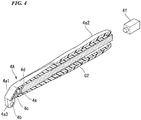
- Fig. 4 is a side cross-sectional view of the handpiece 4 in the modified example of the dental caries diagnosis device 1 according to this embodiment.
- a second embodiment of the dental caries diagnosis device 1 will be described with reference to Figs. 3 and 4 . It should be noted that constituent elements that are the same as the first embodiment will be denoted with the same reference numerals and a description thereof will be omitted.
- a handpiece 4 does not include a camera 4f.
- the cable C3 which is a bundle of optical fibers is accommodated inside a grasp portion 4a2.
- side wall portions 4a3 provided to sandwich an accommodation space of a tooth have end portions formed in a curved surface shape.
- the camera 4f is connected to a cable C3 exposed from the handpiece 4 and receives examination light R transmitted through the cable C3.
- the inspector can use the head-side casing 4a1 in a state in which the head-side casing 4a1 is in non-contact with the tooth or the gum.
- the testee does not feel uncomfortable due to the head-side casing 4a1 in contact with a gum. Therefore, the inspector can smoothly diagnose a dental caries.
- a cut filter 4e is provided in order to prevent the examination light R received by the camera 4f from mixing with external light when the head-side casing 4a1 is brought into non-contact with the tooth or the gum.
- noise is hardly present in an image acquired by the dental caries diagnosis device 1 and it is possible to maintain diagnostic accuracy of the inspector regardless of an external environment.
- the dental caries diagnosis device 1 in this embodiment when an end portion of the side wall portions 4a3 in the head-side casing 4a1 is formed in a curved surface shape and is inserted into the testee's mouth, the testee does not feel pain even when the side wall portion 4a3 touches the testee.
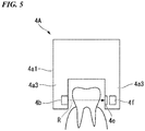
- Fig. 5 is a front view of a head portion 4A of a handpiece 4 in a modified example of the dental caries diagnosis device 1 according to this embodiment.
- a third embodiment of the dental caries diagnosis device 1 will be described with reference to Fig. 5 . It should be noted that constituent elements that are the same as the first embodiment will be denoted with the same reference numerals and a description thereof will be omitted.
- a head portion 4A does not include a prism 4c and includes a cut filter 4e and a camera 4f.
- a light irradiation unit 4b is installed on one of side wall portions 4a3s provided to sandwich a concave accommodation portion of a head-side casing 4a1 and the cut filter 4e and the camera 4f are installed on a side wall portion 4a3 and a side wall portion 4a3 facing the side wall portion 4a3.
- Examination light R irradiated from the light irradiation unit 4b is transmitted through the testee's tooth and is incident on the camera 4f disposed opposite to the light irradiation unit 4b.
- the inspector can use the head-side casing 4a1 in a state in which the head-side casing 4a1 is in non-contact with a tooth or a gum.
- the testee does not feel uncomfortable due to the head-side casing 4a1 in contact with a gum. Therefore, the inspector can smoothly diagnose a dental caries.
- the cut filter 4e is provided in order to prevent examination light R received by the camera 4f from mixing with external light when the head-side casing 4a1 is brought into con-contact with a tooth or a gum.
- the cut filter 4e is provided.
- a noise is hardly present in an image acquired by the dental caries diagnosis device 1 and it is possible to maintain diagnostic accuracy of the inspector regardless of the external environment.
- a distance between the light irradiation unit 4b and the camera 4f is shorter than that in the first embodiment, it is possible to diagnose a dental caries on the basis of high-intensity examination light R. Therefore, the inspector can obtain a higher-accuracy image from the camera 4f and it is possible to further improve dental caries diagnostic accuracy.
- the present invention can be used for a dental caries diagnosis device
Landscapes
- Health & Medical Sciences (AREA)
- Life Sciences & Earth Sciences (AREA)
- Engineering & Computer Science (AREA)
- Surgery (AREA)
- Veterinary Medicine (AREA)
- Public Health (AREA)
- General Health & Medical Sciences (AREA)
- Animal Behavior & Ethology (AREA)
- Biomedical Technology (AREA)
- Biophysics (AREA)
- Molecular Biology (AREA)
- Pathology (AREA)
- Heart & Thoracic Surgery (AREA)
- Medical Informatics (AREA)
- Physics & Mathematics (AREA)
- Oral & Maxillofacial Surgery (AREA)
- Dentistry (AREA)
- Nuclear Medicine, Radiotherapy & Molecular Imaging (AREA)
- Optics & Photonics (AREA)
- Radiology & Medical Imaging (AREA)
- Epidemiology (AREA)
- Signal Processing (AREA)
- Audiology, Speech & Language Pathology (AREA)
- Computer Vision & Pattern Recognition (AREA)
- Artificial Intelligence (AREA)
- Physiology (AREA)
- Psychiatry (AREA)
- Pain & Pain Management (AREA)
- Mechanical Engineering (AREA)
- Endoscopes (AREA)
- Dental Tools And Instruments Or Auxiliary Dental Instruments (AREA)
Abstract
Description
- The present invention relates to a dental caries diagnosis device.
- Priority is claimed on Japanese Patent Application No.
2016-112393, filed June 6, 2016 - For example, Non-Patent Document 1 discloses a dental caries detection image examination device using laser light. The dental caries detection image examination device in Non-Patent Document 1 irradiates a tooth with the laser light, receives the laser light reflected by the tooth, and detects a dental caries from an intensity of the received laser light. Such a dental caries detection image examination device has a structure in which a tooth is surrounded by a laser light irradiation unit using a clip and a noise component due to external light at the time of examining is prevented from entering a light receiving unit.
- Yuusuke KAWASHIMA and three others, "Clinical Science Course, Usefulness for Dental Caries Features and Clinical Dentistry in Latest Dental Caries Detection Image Examination Device Without Exposure to X-rays 'KaVO DIAGNOcam,'" The Nippon Dental Review, January 2014, Reprint, p. 107 to 112
- However, when a dental caries detection image examination device such as that described in Non-Patent Document 1 is used, a laser light irradiation unit is fixed to the gum in the mouth. Thus, a testee whose gum is in contact with the laser light irradiation unit during the examination is likely to feel uncomfortable.
- The present invention was made in view of the above-described problems, and an objective of the present invention is to provide a dental caries diagnosis device that does not cause a testee discomfort.
- A dental caries diagnosis device according to an aspect of the present invention is a dental caries diagnosis device which includes a light source which is configured to emit examination light and a light receiving unit which is configured to receive the examination light with which a tooth has been irradiated including: a head portion which is inserted into a mouth without coming in contact with a tooth or a gum and which projects the examination light toward a tooth; and a filter which is disposed in front of the light receiving unit and which is configured to remove a noise component from the received light, wherein the light receiving unit is configured to receive the examination light which has been transmitted through the tooth.
- In the dental caries diagnosis device according to the aspect, the light source may be a light emitting diode.
- The dental caries diagnosis device according to the aspect may include: a prism or a mirror which is configured to refract the examination light with which the tooth has been irradiated toward the light receiving unit.
- The dental caries diagnosis device according to the aspect may include: a light amount adjustment unit which is configured to adjust the amount of the examination light.
- In the dental caries diagnosis device according to the aspect, the head portion may include: side wall portions which have a tooth accommodation space and are disposed to face each other so that the side wall portions surround the accommodation space; and a light irradiation unit which is configured to irradiate the examination light from the side wall portions toward a tooth.
- According to the present invention, a head portion is inserted into a mouth without coming in contact with a testee's gingiva (gum). For this reason, the testee does not feel uncomfortable. Here, since the head portion is away from a testee's tooth, external light enters the inside of the head portion through a gap between the head portion and the gum and light received by a light receiving unit includes a noise component such as the external light in addition to examination light. In order to remove the noise component other than the examination light from the light received by the light receiving unit, a filter is provided in front of the light receiving unit in the present invention. Thus, an inspector who makes a diagnosis can capture a clear diagnostic image of a dental caries using the head portion that is not in contact with the gum.
-
-
Fig. 1 is a device constitution diagram of a dental caries diagnosis device according to an embodiment of the present invention. -
Fig. 2A is a side cross-sectional view of a handpiece in the dental caries diagnosis device according to the embodiment of the present invention. -
Fig. 2B is a front view of a head portion in the handpiece of the dental caries diagnosis device according to the embodiment of the present invention. -
Fig. 3 is a perspective view of a handpiece in a modified example of the dental caries diagnosis device according to the embodiment of the present invention. -
Fig. 4 is a side cross-sectional view of a handpiece in the modified example of the dental caries diagnosis device according to the embodiment of the present invention. -
Fig. 5 is a front view of a head portion of a handpiece in a modified example of the dental caries diagnosis device according to the embodiment of the present invention. - In the following drawings, in order to set each member to have a distinguishable size, the scale of each member is appropriately changed.
- Embodiments of a dental caries diagnosis device associated with the present invention will be described below with reference to the drawings.
Fig. 1 is a device constitution diagram of a dental caries diagnosis device 1 according to this embodiment. - The dental caries diagnosis device 1 according to this embodiment includes a main body portion 2, a
shutter unit 3, and ahandpiece 4, the main body portion 2 and theshutter unit 3 are connected to each other through a cable C1, and theshutter unit 3 and thehandpiece 4 are connected to each other through a cable C2. The main body portion 2 is a device configured to supply light to thehandpiece 4 and transmit and receive signals to and from a computer P and receives supplied electric power when connected to an electric power strip or the like. The main body portion 2 includes anelectric power switch 2a, a lightamount adjustment unit 2b, and alight source 2c. - The
electric power switch 2a is a switch configured to switch between supply start and supply stop of a power supply. The lightamount adjustment unit 2b is a knob configured to adjust an amount of light of alight irradiation unit 4b which will be described later in thehandpiece 4 and can adjust an amount of light of the light source stepwise or steplessly. The main body portion 2 is connected to theshutter unit 3 through the cable C1 having an optical fiber light guide connected to the light source installed therein. The main body portion 2 is connected to the computer P through a USB cable. The computer P includes a monitor which displays a video from acamera 4f which will be described later. Thelight source 2c is a light emitting diode (LED) with a central wavelength of 780 nm configured to emit examination light R and can an amount of light thereof can be adjusted through adjustment of the lightamount adjustment unit 2b. - The
shutter unit 3 is connected to the main body portion 2 via the cable C1 and is connected to thehandpiece 4 via the cable C2 having the optical fiber light guide installed therein. Theshutter unit 3 is an apparatus which includes ashutter switch 3a and performs a shutter operation of thecamera 4f which will be described later in thehandpiece 4. An inspector can acquire a still image or a moving image through thecamera 4f by pressing down theshutter switch 3a. -
Fig. 2A is a side cross-sectional view of thehandpiece 4 in the dental caries diagnosis device 1 according to this embodiment.Fig. 2B is a front view of ahead portion 4A in thehandpiece 4 of the dental caries diagnosis device 1 according to this embodiment. As shown inFigs. 2A and 2B , thehandpiece 4 includes acasing 4a, thelight irradiation unit 4b, aprism 4c, alens 4d, acut filter 4e, and thecamera 4f (light receiving unit). - The
casing 4a is an elongated member and includes a head-side casing 4a1 and a grasp portion 4a2 which is shown inFig. 1 . Thecasing 4a has a hollow or translucent member formed therein through which the examination light R irradiated from thelight irradiation unit 4b can pass. - The head-side casing 4a1 is a resin part inserted into a testee's mouth and has the
light irradiation unit 4b and theprism 4c embedded therein. As shown inFig. 2 , the head-side casing 4a1 has an accommodation space formed to accommodate a tooth between two side wall portions 4a3 erected in parallel at intervals from a distal end of a substantially tubular member through the two side wall portions 4a3. The width of the two side wall portions 4a3 is set wider than an average value of widths of adult molar teeth. In the head-side casing 4a1, a part of the side wall portions 4a3 is formed of a translucent member and thelight irradiation unit 4b is embedded in a translucent portion of the side wall portions 4a3. Such a head-side casing 4a1 is inserted into the testee's mouth such that a tooth is sandwiched between the two side wall portions 4a3. The head-side casing 4a1 can be detached from the grasp portion 4a2. - The grasp portion 4a2 is a portion by which the inspector grasps the
handpiece 4 in a range not including the head-side casing 4a1 and has the head-side casing 4a1 attached thereto. Thelens 4d, thecut filter 4e, and thecamera 4f are provided inside the grasp portion 4a2. - The
light irradiation unit 4b is embedded in each of the two side wall portions 4a3 in the head-side casing 4a1 and irradiates examination light R from the sides of a tooth root portion inserted into a concave portion. Thelight irradiation units 4b are connected to the light source of the main body portion 2 via the cables C1 and C2 having the optical fiber light guides. Theprism 4c is embedded in a bottom portion of the concave portion in the head-side casing 4a1. Theprism 4c is a member configured to refract examination light R which is irradiated from thelight irradiation unit 4b and passes through the testee's a tooth at 90 degrees toward thecamera 4f. - The
head portion 4A is constituted of the head-side casing 4a1 and thelight irradiation unit 4b and theprism 4c provided inside the head-side casing 4a1. Thehead portion 4A is inserted into the mouth without coming in contact with a tooth or a gum and projects examination light R toward the tooth. Thehead portion 4A can be detached and the inspector can use thehead portion 4A according to a size of the testee's tooth. - The
lens 4d is a part configured to cause examination light R refracted through theprism 4c to converge and is provided inside thecasing 4a. Thecut filter 4e is provided behind thelens 4d and in front of thecamera 4f so that examination light R passing through thelens 4d passes therethrough. Thecut filter 4e is a device configured to remove external light (a noise component) from a fluorescent lamp from light passing through thelens 4d and passes only examination light R with a wavelength of 780 nm. - The
camera 4f is a complementary metal-oxide semiconductor (CMOS) sensor configured to receive light passing through thecut filter 4e and can capture an image and a moving image. Thecamera 4f receives a signal from theshutter unit 3 and captures an image. Thecamera 4f transmits the image and the moving image to the main body portion 2 via the cable C2 and the cable C1. The captured image and moving image are transmitted from the main body portion 2 to the computer P via a USB cable and can be observed on the monitor of the computer P in real time. - An operation of such a dental caries diagnosis device 1 according to this embodiment will be described.
- The inspector first presses the
electric power switch 2a. Thus, the light source is turned on, and examination light R is transmitted to thelight irradiation unit 4b via the optical fiber light guides of the cable C1 and the cable C2. The inspector inserts the head-side casing 4a1 of thehandpiece 4 into the testee's mouth and keeps the head-side casing 4a1 out of contact with the testee's tooth. The examination light R irradiated from thelight irradiation unit 4b is incident on the testee's tooth from the side. When the examination light R is applied to the testee's tooth, the inspector operates the lightamount adjustment unit 2b in accordance with a texture and a size of the testee's tooth, a portion of the tooth to be examined, and the like and adjusts the amount of light. - The examination light R incident on the testee's tooth is refracted and scattered inside the testee's tooth and a part of the examination light R is incident on the
prism 4c from above. At that time, since the testee's mouth is open, the external light from the fluorescent lamp is incident on the prism together with the examination light R. The examination light R incident on theprism 4c is reflected toward thelens 4d and converges through thelens 4d. The examination light R passing through thelens 4d passes through thecut filter 4e. Thus, the external light passing through thelens 4d together with the examination light R is shielded and only the examination light R reaches thecamera 4f. - The inspector can observe the examination light R received by the
camera 4f on the monitor or the like of the computer P in real time. The inspector operates theshutter unit 3 and can acquire the examination light R received by thecamera 4f as an image and a moving image. The inspector detects a dental caries generated inside the testee's tooth from the acquired image. - According to such a dental caries diagnosis device 1 according to this embodiment, the inspector can use the head-side casing 4a1 in a state in which the head-side casing 4a1 is not in contact with a tooth or a gum. Thus, the testee does not feel the discomfort of the head-side casing 4a1 coming in contact with a gum. Therefore, the inspector can smoothly diagnose a dental caries. In order to prevent the examination light R received by the
camera 4f from mixing with external light when the head-side casing 4a1 is not brought into contact with a tooth or a gum, thecut filter 4e is provided. Thus, there is hardly any noise in an image acquired by the dental caries diagnosis device 1 and it is possible to maintain diagnostic accuracy of the inspector regardless of an external environment. - The dental caries diagnosis device 1 according to this embodiment may use an LED as the light source. Thus, the present invention is easy to handle and a size of the entire device can be reduced as compared with the case in which laser light is used for the dental caries diagnosis device in the related art.
- In the dental caries diagnosis device 1 according to this embodiment, the
handpiece 4 includes theprism 4c configured to refract the examination light R toward thecamera 4f. Thus, it is unnecessary to provide thecamera 4f in the head-side casing 4a1 to receive the examination light R which has been transmitted through the testee's tooth. Therefore, even in this case, it is possible to reduce a size of thehead portion 4A inserted into the testee's mouth and the testee becomes less likely to cause discomfort. - The dental caries diagnosis device 1 according to this embodiment can adjust the light
amount adjustment unit 2b to adjust an amount of light of the light source in the main body portion 2. Therefore, the inspector can perform a diagnosis without scattering the examination light R by adjusting an amount of light of the light source, for example, even with a tooth that has high translucency like an infant tooth or a front tooth. - In the dental caries diagnosis device 1 according to this embodiment, the LED with the central wavelength of 780 nm is used as the light source. This is based on the fact that light of a general indoor fluorescent lamp includes little light with a wavelength of 780 nm. Thus, the
cut filter 4e can easily exclude external light from the fluorescent lamp incident together with the examination light R by excluding light other than the light with a wavelength of 780 nm. - With the dental caries diagnosis device 1 according to this embodiment, teeth with various sizes can be coped with by replacing the
head portion 4A with ahead portion 4A having a different width of a concave portion. Therefore, it is possible to observe an infant tooth, a front tooth, and the like that are difficult to observe using the dental caries examination device of the related art. -
Fig. 3 is a perspective view of ahandpiece 4 in a modified example of the dental caries diagnosis device 1 according to this embodiment.Fig. 4 is a side cross-sectional view of thehandpiece 4 in the modified example of the dental caries diagnosis device 1 according to this embodiment. A second embodiment of the dental caries diagnosis device 1 will be described with reference toFigs. 3 and4 . It should be noted that constituent elements that are the same as the first embodiment will be denoted with the same reference numerals and a description thereof will be omitted. - In a dental caries diagnosis device 1 in this embodiment, a
handpiece 4 does not include acamera 4f. As shown inFig. 4 , the cable C3 which is a bundle of optical fibers is accommodated inside a grasp portion 4a2. In an end portion of a head-side casing 4a1 in thehandpiece 4 in this embodiment, side wall portions 4a3 provided to sandwich an accommodation space of a tooth have end portions formed in a curved surface shape. Furthermore, thecamera 4f is connected to a cable C3 exposed from thehandpiece 4 and receives examination light R transmitted through the cable C3. - According to such a dental caries diagnosis device 1 according to this embodiment, as in the first embodiment, the inspector can use the head-side casing 4a1 in a state in which the head-side casing 4a1 is in non-contact with the tooth or the gum. Thus, the testee does not feel uncomfortable due to the head-side casing 4a1 in contact with a gum. Therefore, the inspector can smoothly diagnose a dental caries. In order to prevent the examination light R received by the
camera 4f from mixing with external light when the head-side casing 4a1 is brought into non-contact with the tooth or the gum, acut filter 4e is provided. Thus, noise is hardly present in an image acquired by the dental caries diagnosis device 1 and it is possible to maintain diagnostic accuracy of the inspector regardless of an external environment. - Also, according to the dental caries diagnosis device 1 in this embodiment, when an end portion of the side wall portions 4a3 in the head-side casing 4a1 is formed in a curved surface shape and is inserted into the testee's mouth, the testee does not feel pain even when the side wall portion 4a3 touches the testee.
-
Fig. 5 is a front view of ahead portion 4A of ahandpiece 4 in a modified example of the dental caries diagnosis device 1 according to this embodiment. A third embodiment of the dental caries diagnosis device 1 will be described with reference toFig. 5 . It should be noted that constituent elements that are the same as the first embodiment will be denoted with the same reference numerals and a description thereof will be omitted. - As shown in
Fig. 5 , in a dental caries diagnosis device 1 in this embodiment, ahead portion 4A does not include aprism 4c and includes acut filter 4e and acamera 4f. Alight irradiation unit 4b is installed on one of side wall portions 4a3s provided to sandwich a concave accommodation portion of a head-side casing 4a1 and thecut filter 4e and thecamera 4f are installed on a side wall portion 4a3 and a side wall portion 4a3 facing the side wall portion 4a3. Examination light R irradiated from thelight irradiation unit 4b is transmitted through the testee's tooth and is incident on thecamera 4f disposed opposite to thelight irradiation unit 4b. - According to such as dental caries diagnosis device 1 associated with this embodiment, as in the first embodiment, the inspector can use the head-side casing 4a1 in a state in which the head-side casing 4a1 is in non-contact with a tooth or a gum. Thus, the testee does not feel uncomfortable due to the head-side casing 4a1 in contact with a gum. Therefore, the inspector can smoothly diagnose a dental caries. In order to prevent examination light R received by the
camera 4f from mixing with external light when the head-side casing 4a1 is brought into con-contact with a tooth or a gum, thecut filter 4e is provided. Thus, a noise is hardly present in an image acquired by the dental caries diagnosis device 1 and it is possible to maintain diagnostic accuracy of the inspector regardless of the external environment. - According to this embodiment, since a distance between the
light irradiation unit 4b and thecamera 4f is shorter than that in the first embodiment, it is possible to diagnose a dental caries on the basis of high-intensity examination light R. Therefore, the inspector can obtain a higher-accuracy image from thecamera 4f and it is possible to further improve dental caries diagnostic accuracy. - The present invention is not limited to the above-described embodiments, and for example, the following modified examples are conceivable.
- (1) Although the main body portion 2 and the computer P are connected through the USB cable in the above-described embodiments, the present invention is not limited thereto. The main body portion 2 and the computer P may be connected by radio. The main body portion 2 may be connected to, for example, a tablet or the like.
- (2) Although the
shutter unit 3 is provided as a separate member from the main body portion 2 and thehandpiece 4 in the above-described embodiment, the present invention is not limited thereto. Theshutter unit 3 may be provided in the main body portion 2 or thehandpiece 4. In this case, since a device constitution can be simplified, it is easy to carry the dental caries diagnosis device 1. - (3) Although the
handpiece 4 includes theprism 4c in the first embodiment, the present invention is not limited thereto. Thehandpiece 4 may include a mirror and reflect light which has been transmitted through the testee's tooth toward thecamera 4f using the mirror. - The present invention can be used for a dental caries diagnosis device
-
- 1 Dental caries diagnosis device
- 2 Main body portion
- 2a Electric power switch
- 2b Light amount adjustment unit
- 3 Shutter unit
- 3a Shutter switch
- 4 Handpiece
- 4A Head portion
- 4a3 Side wall portion
- 4b Light irradiation unit
- 4c Prism
- 4e Cut filter
- 4f Camera (light receiving unit)
Claims (12)
- A dental caries diagnosis device which includes a light source which is configured to emit examination light and a light receiving unit which is configured to receive the examination light with which a tooth has been irradiated comprising:a head portion which is inserted into a mouth without coming in contact with a tooth or a gum and which projects the examination light toward a tooth; anda filter which is disposed in front of the light receiving unit and which is configured to remove a noise component from the received light,wherein the light receiving unit is configured to receive the examination light which has been transmitted through the tooth.
- The dental caries diagnosis device according to claim 1, wherein the light source is a light emitting diode.
- The dental caries diagnosis device according to claim 1, comprising a prism or a mirror which is configured to refract the examination light with which the tooth has been irradiated toward the light receiving unit.
- The dental caries diagnosis device according to claim 1, comprising a light amount adjustment unit which is configured to adjust an amount of the examination light.
- The dental caries diagnosis device according to any one of claims 1 to 4, wherein the head portion includes: side wall portions which have a tooth accommodation space and are disposed to face each other so that the side wall portions surround the accommodation space; and a light irradiation unit which is configured to irradiate the examination light from the side wall portions toward a tooth.
- The dental caries diagnosis device according to claim 2, comprising a prism or a mirror which is configured to refract the examination light with which the tooth has been irradiated to the light receiving unit.
- The dental caries diagnosis device according to claim 6, comprising a light amount adjustment unit which is configured to adjust an amount of the examination light.
- The dental caries diagnosis device according to claim 6 or 7, wherein the head portion includes: side wall portions which have a tooth accommodation space and are disposed to face each other across the accommodation space; and a light irradiation unit which is configured to irradiate the examination light from the side wall portions toward a tooth.
- The dental caries diagnosis device according to claim 2, comprising a light amount adjustment unit which is configured to adjust an amount of the examination light.
- The dental caries diagnosis device according to claim 9, wherein the head portion includes: side wall portions which have a tooth accommodation space and are disposed to face each other across the accommodation space; and a light irradiation unit which is configured to irradiate the examination light from the side wall portions toward a tooth.
- The dental caries diagnosis device according to claim 3, comprising a light amount adjustment unit which is configured to adjust an amount of the examination light.
- The dental caries diagnosis device according to claim 11, wherein the head portion includes: side wall portions which have a tooth accommodation space and are disposed to face each other across the accommodation space; and a light irradiation unit which is configured to irradiate the examination light from the side wall portions toward a tooth.
Applications Claiming Priority (2)
| Application Number | Priority Date | Filing Date | Title |
|---|---|---|---|
| JP2016112393 | 2016-06-06 | ||
| PCT/JP2017/020836 WO2017213091A1 (en) | 2016-06-06 | 2017-06-05 | Dental caries diagnosis device |
Publications (3)
| Publication Number | Publication Date |
|---|---|
| EP3466318A1 true EP3466318A1 (en) | 2019-04-10 |
| EP3466318A4 EP3466318A4 (en) | 2020-02-19 |
| EP3466318B1 EP3466318B1 (en) | 2021-04-21 |
Family
ID=60578703
Family Applications (1)
| Application Number | Title | Priority Date | Filing Date |
|---|---|---|---|
| EP17810266.1A Active EP3466318B1 (en) | 2016-06-06 | 2017-06-05 | Dental caries diagnosis device with a head portion defining a tooth accommodation space |
Country Status (4)
| Country | Link |
|---|---|
| US (1) | US11109752B2 (en) |
| EP (1) | EP3466318B1 (en) |
| JP (1) | JP6550653B2 (en) |
| WO (1) | WO2017213091A1 (en) |
Families Citing this family (10)
| Publication number | Priority date | Publication date | Assignee | Title |
|---|---|---|---|---|
| USD916288S1 (en) | 2019-03-12 | 2021-04-13 | 3Shape A/S | Handheld intraoral scanner |
| USD910850S1 (en) | 2019-03-12 | 2021-02-16 | 3Shape A/S | Handheld intraoral scanner |
| CN111839978B (en) * | 2020-07-27 | 2022-07-22 | 河北医科大学第二医院 | An oral surgical lamp |
| JP7093587B1 (en) * | 2021-06-28 | 2022-06-30 | 株式会社吉田製作所 | Optical coherence tomographic image generator and dental CADCAM device |
| USD1048401S1 (en) | 2022-12-08 | 2024-10-22 | 3Shape A/S | Scanner tip |
| USD1101031S1 (en) | 2022-12-08 | 2025-11-04 | 3Shape A/S | Scanner without tip |
| USD1051387S1 (en) | 2022-12-08 | 2024-11-12 | 3Shape A/S | Scanner with a tip |
| USD1055287S1 (en) | 2023-02-10 | 2024-12-24 | 3Shape A/S | Articulator plate |
| USD1101184S1 (en) | 2023-02-10 | 2025-11-04 | Sshape A/S | Lab scanner |
| US20250127400A1 (en) * | 2023-10-24 | 2025-04-24 | Dentsply Sirona Inc. | Contactless detection of defective tooth material |
Family Cites Families (16)
| Publication number | Priority date | Publication date | Assignee | Title |
|---|---|---|---|---|
| DE10013210A1 (en) | 2000-03-17 | 2001-09-20 | Kaltenbach & Voigt | Device for the detection of caries, plaque, bacterial infestation, calculus, tartar and other fluorescent substances on teeth |
| WO2005013843A2 (en) | 2003-08-08 | 2005-02-17 | The Regents Of The Univeristy Of California | Near-infrared transillumination for the imaging of early dental decay |
| JP2009518139A (en) * | 2005-12-08 | 2009-05-07 | ピーター・エス・ラブリー | Infrared dental imaging |
| US20080062429A1 (en) * | 2006-09-12 | 2008-03-13 | Rongguang Liang | Low coherence dental oct imaging |
| DE102007013355A1 (en) | 2007-03-16 | 2008-09-18 | Dürr Dental GmbH & Co. KG | Diagnostic camera and attachment for the realization of such |
| JP2009090091A (en) * | 2007-09-18 | 2009-04-30 | Olympus Corp | Dental observation apparatus |
| WO2009140757A1 (en) * | 2008-05-20 | 2009-11-26 | University Health Network | Device and method for fluorescence-based imaging and monitoring |
| US20100112511A1 (en) * | 2008-11-04 | 2010-05-06 | Paul Neng-Wei Wu | Reflecting-Type Optical Inspection Apparatus and Related Dental Inspection System |
| NL2004154C2 (en) * | 2010-01-04 | 2011-07-05 | Elisabeth Wilhelmina Hendrika Laan | DEVICE AND METHOD FOR DETERMINING THE STATE OF A TOOTH, A DIAL OR ANOTHER BODY PART. |
| WO2011140664A2 (en) | 2010-05-13 | 2011-11-17 | Quantum Dental Technologies Inc. | Handpiece with integrated optical system for photothermal radiometry and luminescence measurements |
| WO2012002564A1 (en) * | 2010-06-29 | 2012-01-05 | 株式会社アドバンス | Intraoral imaging system |
| GB201011913D0 (en) * | 2010-07-15 | 2010-09-01 | Lux Innovate Ltd | Detecting device |
| JP2012147909A (en) * | 2011-01-18 | 2012-08-09 | Olympus Corp | Tooth observation apparatus |
| CN105050537B (en) * | 2012-09-14 | 2017-11-03 | 3M创新有限公司 | Dentistry irradiation unit, dentistry irradiation system |
| US9500635B2 (en) * | 2012-12-31 | 2016-11-22 | Omni Medsci, Inc. | Short-wave infrared super-continuum lasers for early detection of dental caries |
| JP5867642B1 (en) | 2015-07-24 | 2016-02-24 | 株式会社オリンピア | Game machine |
-
2017
- 2017-06-05 JP JP2018522480A patent/JP6550653B2/en active Active
- 2017-06-05 EP EP17810266.1A patent/EP3466318B1/en active Active
- 2017-06-05 US US16/306,985 patent/US11109752B2/en not_active Expired - Fee Related
- 2017-06-05 WO PCT/JP2017/020836 patent/WO2017213091A1/en not_active Ceased
Also Published As
| Publication number | Publication date |
|---|---|
| JP6550653B2 (en) | 2019-08-07 |
| EP3466318A4 (en) | 2020-02-19 |
| US20190142261A1 (en) | 2019-05-16 |
| JPWO2017213091A1 (en) | 2019-06-20 |
| US11109752B2 (en) | 2021-09-07 |
| WO2017213091A1 (en) | 2017-12-14 |
| EP3466318B1 (en) | 2021-04-21 |
Similar Documents
| Publication | Publication Date | Title |
|---|---|---|
| US11109752B2 (en) | Dental caries diagnosis device | |
| US9603530B2 (en) | Dental system for trans-illumination of teeth | |
| US20120122051A1 (en) | Dental Device with Hand-held Instrument and Light Source | |
| US11298013B2 (en) | Apparatus and methods for performing body imaging | |
| JP3644932B2 (en) | Dental camera | |
| CN102947682A (en) | Handpiece with integrated optical system for photothermal radiometry and luminescence measurements | |
| JP2018134418A (en) | Photographing evaluation/detection unit and optical device | |
| US20240268935A1 (en) | Intraoral scanning | |
| US20100040993A1 (en) | Apparatus and method for detecting dental pathologies | |
| KR20180136063A (en) | Apparatus and method for acquiring diagnostic images of teeth by near-infrared | |
| WO2021224929A1 (en) | Intraoral scanner | |
| KR101730648B1 (en) | Multi-health information acquisition device | |
| US20120122052A1 (en) | Medical, in Particular Dental, Diagnostic Device Having Image Capture Means | |
| KR101528610B1 (en) | Lighting Device using optical fiber for diagnosing dental caries and fluorosis | |
| EP3228241A1 (en) | Dental probe | |
| US20120130254A1 (en) | Dental Device for Trans-illumination of Teeth | |
| KR101701921B1 (en) | Device for Taking Image Inside Oral Cavity | |
| CN117545414A (en) | Device for inspecting tissue or attachment in oral cavity and inspection auxiliary member | |
| KR101904830B1 (en) | Optical imaging system for oral cavity | |
| JP2004154211A (en) | Oral observation device | |
| US20200113499A1 (en) | Medical examination device | |
| CN210902965U (en) | Dental caries observer | |
| KR20180030285A (en) | Apparatus for diagnosting oral using light | |
| JP4623466B2 (en) | Tooth diagnostic inspection device | |
| JP2015228887A (en) | Fiberscope and dental probe |
Legal Events
| Date | Code | Title | Description |
|---|---|---|---|
| STAA | Information on the status of an ep patent application or granted ep patent |
Free format text: STATUS: THE INTERNATIONAL PUBLICATION HAS BEEN MADE |
|
| PUAI | Public reference made under article 153(3) epc to a published international application that has entered the european phase |
Free format text: ORIGINAL CODE: 0009012 |
|
| STAA | Information on the status of an ep patent application or granted ep patent |
Free format text: STATUS: REQUEST FOR EXAMINATION WAS MADE |
|
| 17P | Request for examination filed |
Effective date: 20181206 |
|
| AK | Designated contracting states |
Kind code of ref document: A1 Designated state(s): AL AT BE BG CH CY CZ DE DK EE ES FI FR GB GR HR HU IE IS IT LI LT LU LV MC MK MT NL NO PL PT RO RS SE SI SK SM TR |
|
| AX | Request for extension of the european patent |
Extension state: BA ME |
|
| DAV | Request for validation of the european patent (deleted) | ||
| DAX | Request for extension of the european patent (deleted) | ||
| REG | Reference to a national code |
Ref country code: DE Ref legal event code: R079 Ref document number: 602017037256 Country of ref document: DE Free format text: PREVIOUS MAIN CLASS: A61B0001240000 Ipc: A61B0001000000 |
|
| A4 | Supplementary search report drawn up and despatched |
Effective date: 20200117 |
|
| RIC1 | Information provided on ipc code assigned before grant |
Ipc: A61C 19/04 20060101ALI20200113BHEP Ipc: A61B 5/00 20060101ALI20200113BHEP Ipc: A61B 1/24 20060101ALI20200113BHEP Ipc: A61B 1/00 20060101AFI20200113BHEP |
|
| GRAP | Despatch of communication of intention to grant a patent |
Free format text: ORIGINAL CODE: EPIDOSNIGR1 |
|
| STAA | Information on the status of an ep patent application or granted ep patent |
Free format text: STATUS: GRANT OF PATENT IS INTENDED |
|
| INTG | Intention to grant announced |
Effective date: 20201116 |
|
| GRAS | Grant fee paid |
Free format text: ORIGINAL CODE: EPIDOSNIGR3 |
|
| GRAA | (expected) grant |
Free format text: ORIGINAL CODE: 0009210 |
|
| STAA | Information on the status of an ep patent application or granted ep patent |
Free format text: STATUS: THE PATENT HAS BEEN GRANTED |
|
| AK | Designated contracting states |
Kind code of ref document: B1 Designated state(s): AL AT BE BG CH CY CZ DE DK EE ES FI FR GB GR HR HU IE IS IT LI LT LU LV MC MK MT NL NO PL PT RO RS SE SI SK SM TR |
|
| REG | Reference to a national code |
Ref country code: GB Ref legal event code: FG4D |
|
| REG | Reference to a national code |
Ref country code: CH Ref legal event code: EP |
|
| REG | Reference to a national code |
Ref country code: DE Ref legal event code: R096 Ref document number: 602017037256 Country of ref document: DE Ref country code: IE Ref legal event code: FG4D |
|
| REG | Reference to a national code |
Ref country code: AT Ref legal event code: REF Ref document number: 1383759 Country of ref document: AT Kind code of ref document: T Effective date: 20210515 |
|
| PGFP | Annual fee paid to national office [announced via postgrant information from national office to epo] |
Ref country code: DE Payment date: 20210629 Year of fee payment: 5 Ref country code: FR Payment date: 20210625 Year of fee payment: 5 |
|
| REG | Reference to a national code |
Ref country code: LT Ref legal event code: MG9D |
|
| PGFP | Annual fee paid to national office [announced via postgrant information from national office to epo] |
Ref country code: GB Payment date: 20210628 Year of fee payment: 5 |
|
| REG | Reference to a national code |
Ref country code: AT Ref legal event code: MK05 Ref document number: 1383759 Country of ref document: AT Kind code of ref document: T Effective date: 20210421 |
|
| REG | Reference to a national code |
Ref country code: NL Ref legal event code: MP Effective date: 20210421 |
|
| PG25 | Lapsed in a contracting state [announced via postgrant information from national office to epo] |
Ref country code: LT Free format text: LAPSE BECAUSE OF FAILURE TO SUBMIT A TRANSLATION OF THE DESCRIPTION OR TO PAY THE FEE WITHIN THE PRESCRIBED TIME-LIMIT Effective date: 20210421 Ref country code: FI Free format text: LAPSE BECAUSE OF FAILURE TO SUBMIT A TRANSLATION OF THE DESCRIPTION OR TO PAY THE FEE WITHIN THE PRESCRIBED TIME-LIMIT Effective date: 20210421 Ref country code: NL Free format text: LAPSE BECAUSE OF FAILURE TO SUBMIT A TRANSLATION OF THE DESCRIPTION OR TO PAY THE FEE WITHIN THE PRESCRIBED TIME-LIMIT Effective date: 20210421 Ref country code: BG Free format text: LAPSE BECAUSE OF FAILURE TO SUBMIT A TRANSLATION OF THE DESCRIPTION OR TO PAY THE FEE WITHIN THE PRESCRIBED TIME-LIMIT Effective date: 20210721 Ref country code: AT Free format text: LAPSE BECAUSE OF FAILURE TO SUBMIT A TRANSLATION OF THE DESCRIPTION OR TO PAY THE FEE WITHIN THE PRESCRIBED TIME-LIMIT Effective date: 20210421 Ref country code: HR Free format text: LAPSE BECAUSE OF FAILURE TO SUBMIT A TRANSLATION OF THE DESCRIPTION OR TO PAY THE FEE WITHIN THE PRESCRIBED TIME-LIMIT Effective date: 20210421 |
|
| PG25 | Lapsed in a contracting state [announced via postgrant information from national office to epo] |
Ref country code: SE Free format text: LAPSE BECAUSE OF FAILURE TO SUBMIT A TRANSLATION OF THE DESCRIPTION OR TO PAY THE FEE WITHIN THE PRESCRIBED TIME-LIMIT Effective date: 20210421 Ref country code: RS Free format text: LAPSE BECAUSE OF FAILURE TO SUBMIT A TRANSLATION OF THE DESCRIPTION OR TO PAY THE FEE WITHIN THE PRESCRIBED TIME-LIMIT Effective date: 20210421 Ref country code: PL Free format text: LAPSE BECAUSE OF FAILURE TO SUBMIT A TRANSLATION OF THE DESCRIPTION OR TO PAY THE FEE WITHIN THE PRESCRIBED TIME-LIMIT Effective date: 20210421 Ref country code: NO Free format text: LAPSE BECAUSE OF FAILURE TO SUBMIT A TRANSLATION OF THE DESCRIPTION OR TO PAY THE FEE WITHIN THE PRESCRIBED TIME-LIMIT Effective date: 20210721 Ref country code: LV Free format text: LAPSE BECAUSE OF FAILURE TO SUBMIT A TRANSLATION OF THE DESCRIPTION OR TO PAY THE FEE WITHIN THE PRESCRIBED TIME-LIMIT Effective date: 20210421 Ref country code: PT Free format text: LAPSE BECAUSE OF FAILURE TO SUBMIT A TRANSLATION OF THE DESCRIPTION OR TO PAY THE FEE WITHIN THE PRESCRIBED TIME-LIMIT Effective date: 20210823 Ref country code: GR Free format text: LAPSE BECAUSE OF FAILURE TO SUBMIT A TRANSLATION OF THE DESCRIPTION OR TO PAY THE FEE WITHIN THE PRESCRIBED TIME-LIMIT Effective date: 20210722 Ref country code: IS Free format text: LAPSE BECAUSE OF FAILURE TO SUBMIT A TRANSLATION OF THE DESCRIPTION OR TO PAY THE FEE WITHIN THE PRESCRIBED TIME-LIMIT Effective date: 20210821 |
|
| REG | Reference to a national code |
Ref country code: DE Ref legal event code: R097 Ref document number: 602017037256 Country of ref document: DE |
|
| PG25 | Lapsed in a contracting state [announced via postgrant information from national office to epo] |
Ref country code: ES Free format text: LAPSE BECAUSE OF FAILURE TO SUBMIT A TRANSLATION OF THE DESCRIPTION OR TO PAY THE FEE WITHIN THE PRESCRIBED TIME-LIMIT Effective date: 20210421 Ref country code: SM Free format text: LAPSE BECAUSE OF FAILURE TO SUBMIT A TRANSLATION OF THE DESCRIPTION OR TO PAY THE FEE WITHIN THE PRESCRIBED TIME-LIMIT Effective date: 20210421 Ref country code: SK Free format text: LAPSE BECAUSE OF FAILURE TO SUBMIT A TRANSLATION OF THE DESCRIPTION OR TO PAY THE FEE WITHIN THE PRESCRIBED TIME-LIMIT Effective date: 20210421 Ref country code: RO Free format text: LAPSE BECAUSE OF FAILURE TO SUBMIT A TRANSLATION OF THE DESCRIPTION OR TO PAY THE FEE WITHIN THE PRESCRIBED TIME-LIMIT Effective date: 20210421 Ref country code: EE Free format text: LAPSE BECAUSE OF FAILURE TO SUBMIT A TRANSLATION OF THE DESCRIPTION OR TO PAY THE FEE WITHIN THE PRESCRIBED TIME-LIMIT Effective date: 20210421 Ref country code: CZ Free format text: LAPSE BECAUSE OF FAILURE TO SUBMIT A TRANSLATION OF THE DESCRIPTION OR TO PAY THE FEE WITHIN THE PRESCRIBED TIME-LIMIT Effective date: 20210421 Ref country code: DK Free format text: LAPSE BECAUSE OF FAILURE TO SUBMIT A TRANSLATION OF THE DESCRIPTION OR TO PAY THE FEE WITHIN THE PRESCRIBED TIME-LIMIT Effective date: 20210421 Ref country code: MC Free format text: LAPSE BECAUSE OF FAILURE TO SUBMIT A TRANSLATION OF THE DESCRIPTION OR TO PAY THE FEE WITHIN THE PRESCRIBED TIME-LIMIT Effective date: 20210421 |
|
| REG | Reference to a national code |
Ref country code: CH Ref legal event code: PL |
|
| PLBE | No opposition filed within time limit |
Free format text: ORIGINAL CODE: 0009261 |
|
| STAA | Information on the status of an ep patent application or granted ep patent |
Free format text: STATUS: NO OPPOSITION FILED WITHIN TIME LIMIT |
|
| REG | Reference to a national code |
Ref country code: BE Ref legal event code: MM Effective date: 20210630 |
|
| 26N | No opposition filed |
Effective date: 20220124 |
|
| PG25 | Lapsed in a contracting state [announced via postgrant information from national office to epo] |
Ref country code: LU Free format text: LAPSE BECAUSE OF NON-PAYMENT OF DUE FEES Effective date: 20210605 |
|
| PG25 | Lapsed in a contracting state [announced via postgrant information from national office to epo] |
Ref country code: LI Free format text: LAPSE BECAUSE OF NON-PAYMENT OF DUE FEES Effective date: 20210630 Ref country code: IE Free format text: LAPSE BECAUSE OF NON-PAYMENT OF DUE FEES Effective date: 20210605 Ref country code: CH Free format text: LAPSE BECAUSE OF NON-PAYMENT OF DUE FEES Effective date: 20210630 |
|
| PG25 | Lapsed in a contracting state [announced via postgrant information from national office to epo] |
Ref country code: IS Free format text: LAPSE BECAUSE OF FAILURE TO SUBMIT A TRANSLATION OF THE DESCRIPTION OR TO PAY THE FEE WITHIN THE PRESCRIBED TIME-LIMIT Effective date: 20210821 Ref country code: AL Free format text: LAPSE BECAUSE OF FAILURE TO SUBMIT A TRANSLATION OF THE DESCRIPTION OR TO PAY THE FEE WITHIN THE PRESCRIBED TIME-LIMIT Effective date: 20210421 |
|
| PG25 | Lapsed in a contracting state [announced via postgrant information from national office to epo] |
Ref country code: IT Free format text: LAPSE BECAUSE OF FAILURE TO SUBMIT A TRANSLATION OF THE DESCRIPTION OR TO PAY THE FEE WITHIN THE PRESCRIBED TIME-LIMIT Effective date: 20210421 Ref country code: BE Free format text: LAPSE BECAUSE OF NON-PAYMENT OF DUE FEES Effective date: 20210630 |
|
| REG | Reference to a national code |
Ref country code: DE Ref legal event code: R119 Ref document number: 602017037256 Country of ref document: DE |
|
| GBPC | Gb: european patent ceased through non-payment of renewal fee |
Effective date: 20220605 |
|
| PG25 | Lapsed in a contracting state [announced via postgrant information from national office to epo] |
Ref country code: FR Free format text: LAPSE BECAUSE OF NON-PAYMENT OF DUE FEES Effective date: 20220630 |
|
| PG25 | Lapsed in a contracting state [announced via postgrant information from national office to epo] |
Ref country code: GB Free format text: LAPSE BECAUSE OF NON-PAYMENT OF DUE FEES Effective date: 20220605 Ref country code: DE Free format text: LAPSE BECAUSE OF NON-PAYMENT OF DUE FEES Effective date: 20230103 |
|
| PG25 | Lapsed in a contracting state [announced via postgrant information from national office to epo] |
Ref country code: CY Free format text: LAPSE BECAUSE OF FAILURE TO SUBMIT A TRANSLATION OF THE DESCRIPTION OR TO PAY THE FEE WITHIN THE PRESCRIBED TIME-LIMIT Effective date: 20210421 |
|
| PG25 | Lapsed in a contracting state [announced via postgrant information from national office to epo] |
Ref country code: HU Free format text: LAPSE BECAUSE OF FAILURE TO SUBMIT A TRANSLATION OF THE DESCRIPTION OR TO PAY THE FEE WITHIN THE PRESCRIBED TIME-LIMIT; INVALID AB INITIO Effective date: 20170605 |
|
| PG25 | Lapsed in a contracting state [announced via postgrant information from national office to epo] |
Ref country code: MK Free format text: LAPSE BECAUSE OF FAILURE TO SUBMIT A TRANSLATION OF THE DESCRIPTION OR TO PAY THE FEE WITHIN THE PRESCRIBED TIME-LIMIT Effective date: 20210421 |
|
| PG25 | Lapsed in a contracting state [announced via postgrant information from national office to epo] |
Ref country code: TR Free format text: LAPSE BECAUSE OF FAILURE TO SUBMIT A TRANSLATION OF THE DESCRIPTION OR TO PAY THE FEE WITHIN THE PRESCRIBED TIME-LIMIT Effective date: 20210421 |
|
| PG25 | Lapsed in a contracting state [announced via postgrant information from national office to epo] |
Ref country code: MT Free format text: LAPSE BECAUSE OF FAILURE TO SUBMIT A TRANSLATION OF THE DESCRIPTION OR TO PAY THE FEE WITHIN THE PRESCRIBED TIME-LIMIT Effective date: 20210421 |