EP3465867B1 - Transformer for measuring a common mode current and method of determining a common mode current - Google Patents
Transformer for measuring a common mode current and method of determining a common mode current Download PDFInfo
- Publication number
- EP3465867B1 EP3465867B1 EP17810786.8A EP17810786A EP3465867B1 EP 3465867 B1 EP3465867 B1 EP 3465867B1 EP 17810786 A EP17810786 A EP 17810786A EP 3465867 B1 EP3465867 B1 EP 3465867B1
- Authority
- EP
- European Patent Office
- Prior art keywords
- current
- core
- winding
- drive
- transformer
- Prior art date
- Legal status (The legal status is an assumption and is not a legal conclusion. Google has not performed a legal analysis and makes no representation as to the accuracy of the status listed.)
- Active
Links
Images








Classifications
-
- B—PERFORMING OPERATIONS; TRANSPORTING
- B60—VEHICLES IN GENERAL
- B60L—PROPULSION OF ELECTRICALLY-PROPELLED VEHICLES; SUPPLYING ELECTRIC POWER FOR AUXILIARY EQUIPMENT OF ELECTRICALLY-PROPELLED VEHICLES; ELECTRODYNAMIC BRAKE SYSTEMS FOR VEHICLES IN GENERAL; MAGNETIC SUSPENSION OR LEVITATION FOR VEHICLES; MONITORING OPERATING VARIABLES OF ELECTRICALLY-PROPELLED VEHICLES; ELECTRIC SAFETY DEVICES FOR ELECTRICALLY-PROPELLED VEHICLES
- B60L3/00—Electric devices on electrically-propelled vehicles for safety purposes; Monitoring operating variables, e.g. speed, deceleration or energy consumption
- B60L3/0023—Detecting, eliminating, remedying or compensating for drive train abnormalities, e.g. failures within the drive train
- B60L3/0069—Detecting, eliminating, remedying or compensating for drive train abnormalities, e.g. failures within the drive train relating to the isolation, e.g. ground fault or leak current
-
- B—PERFORMING OPERATIONS; TRANSPORTING
- B60—VEHICLES IN GENERAL
- B60L—PROPULSION OF ELECTRICALLY-PROPELLED VEHICLES; SUPPLYING ELECTRIC POWER FOR AUXILIARY EQUIPMENT OF ELECTRICALLY-PROPELLED VEHICLES; ELECTRODYNAMIC BRAKE SYSTEMS FOR VEHICLES IN GENERAL; MAGNETIC SUSPENSION OR LEVITATION FOR VEHICLES; MONITORING OPERATING VARIABLES OF ELECTRICALLY-PROPELLED VEHICLES; ELECTRIC SAFETY DEVICES FOR ELECTRICALLY-PROPELLED VEHICLES
- B60L53/00—Methods of charging batteries, specially adapted for electric vehicles; Charging stations or on-board charging equipment therefor; Exchange of energy storage elements in electric vehicles
-
- B—PERFORMING OPERATIONS; TRANSPORTING
- B60—VEHICLES IN GENERAL
- B60L—PROPULSION OF ELECTRICALLY-PROPELLED VEHICLES; SUPPLYING ELECTRIC POWER FOR AUXILIARY EQUIPMENT OF ELECTRICALLY-PROPELLED VEHICLES; ELECTRODYNAMIC BRAKE SYSTEMS FOR VEHICLES IN GENERAL; MAGNETIC SUSPENSION OR LEVITATION FOR VEHICLES; MONITORING OPERATING VARIABLES OF ELECTRICALLY-PROPELLED VEHICLES; ELECTRIC SAFETY DEVICES FOR ELECTRICALLY-PROPELLED VEHICLES
- B60L53/00—Methods of charging batteries, specially adapted for electric vehicles; Charging stations or on-board charging equipment therefor; Exchange of energy storage elements in electric vehicles
- B60L53/50—Charging stations characterised by energy-storage or power-generation means
-
- B—PERFORMING OPERATIONS; TRANSPORTING
- B60—VEHICLES IN GENERAL
- B60L—PROPULSION OF ELECTRICALLY-PROPELLED VEHICLES; SUPPLYING ELECTRIC POWER FOR AUXILIARY EQUIPMENT OF ELECTRICALLY-PROPELLED VEHICLES; ELECTRODYNAMIC BRAKE SYSTEMS FOR VEHICLES IN GENERAL; MAGNETIC SUSPENSION OR LEVITATION FOR VEHICLES; MONITORING OPERATING VARIABLES OF ELECTRICALLY-PROPELLED VEHICLES; ELECTRIC SAFETY DEVICES FOR ELECTRICALLY-PROPELLED VEHICLES
- B60L53/00—Methods of charging batteries, specially adapted for electric vehicles; Charging stations or on-board charging equipment therefor; Exchange of energy storage elements in electric vehicles
- B60L53/60—Monitoring or controlling charging stations
- B60L53/66—Data transfer between charging stations and vehicles
-
- G—PHYSICS
- G01—MEASURING; TESTING
- G01R—MEASURING ELECTRIC VARIABLES; MEASURING MAGNETIC VARIABLES
- G01R15/00—Details of measuring arrangements of the types provided for in groups G01R17/00 - G01R29/00, G01R33/00 - G01R33/26 or G01R35/00
- G01R15/14—Adaptations providing voltage or current isolation, e.g. for high-voltage or high-current networks
- G01R15/18—Adaptations providing voltage or current isolation, e.g. for high-voltage or high-current networks using inductive devices, e.g. transformers
- G01R15/183—Adaptations providing voltage or current isolation, e.g. for high-voltage or high-current networks using inductive devices, e.g. transformers using transformers with a magnetic core
- G01R15/185—Adaptations providing voltage or current isolation, e.g. for high-voltage or high-current networks using inductive devices, e.g. transformers using transformers with a magnetic core with compensation or feedback windings or interacting coils, e.g. 0-flux sensors
-
- G—PHYSICS
- G01—MEASURING; TESTING
- G01R—MEASURING ELECTRIC VARIABLES; MEASURING MAGNETIC VARIABLES
- G01R27/00—Arrangements for measuring resistance, reactance, impedance, or electric characteristics derived therefrom
- G01R27/02—Measuring real or complex resistance, reactance, impedance, or other two-pole characteristics derived therefrom, e.g. time constant
- G01R27/16—Measuring impedance of element or network through which a current is passing from another source, e.g. cable, power line
- G01R27/18—Measuring resistance to earth, i.e. line to ground
-
- G—PHYSICS
- G01—MEASURING; TESTING
- G01R—MEASURING ELECTRIC VARIABLES; MEASURING MAGNETIC VARIABLES
- G01R27/00—Arrangements for measuring resistance, reactance, impedance, or electric characteristics derived therefrom
- G01R27/02—Measuring real or complex resistance, reactance, impedance, or other two-pole characteristics derived therefrom, e.g. time constant
- G01R27/20—Measuring earth resistance; Measuring contact resistance, e.g. of earth connections, e.g. plates
-
- G—PHYSICS
- G01—MEASURING; TESTING
- G01R—MEASURING ELECTRIC VARIABLES; MEASURING MAGNETIC VARIABLES
- G01R31/00—Arrangements for testing electric properties; Arrangements for locating electric faults; Arrangements for electrical testing characterised by what is being tested not provided for elsewhere
- G01R31/005—Testing of electric installations on transport means
- G01R31/006—Testing of electric installations on transport means on road vehicles, e.g. automobiles or trucks
-
- G—PHYSICS
- G05—CONTROLLING; REGULATING
- G05F—SYSTEMS FOR REGULATING ELECTRIC OR MAGNETIC VARIABLES
- G05F1/00—Automatic systems in which deviations of an electric quantity from one or more predetermined values are detected at the output of the system and fed back to a device within the system to restore the detected quantity to its predetermined value or values, i.e. retroactive systems
- G05F1/10—Regulating voltage or current
-
- H—ELECTRICITY
- H02—GENERATION; CONVERSION OR DISTRIBUTION OF ELECTRIC POWER
- H02H—EMERGENCY PROTECTIVE CIRCUIT ARRANGEMENTS
- H02H1/00—Details of emergency protective circuit arrangements
- H02H1/0007—Details of emergency protective circuit arrangements concerning the detecting means
-
- H—ELECTRICITY
- H02—GENERATION; CONVERSION OR DISTRIBUTION OF ELECTRIC POWER
- H02H—EMERGENCY PROTECTIVE CIRCUIT ARRANGEMENTS
- H02H3/00—Emergency protective circuit arrangements for automatic disconnection directly responsive to an undesired change from normal electric working condition with or without subsequent reconnection ; integrated protection
-
- H—ELECTRICITY
- H02—GENERATION; CONVERSION OR DISTRIBUTION OF ELECTRIC POWER
- H02H—EMERGENCY PROTECTIVE CIRCUIT ARRANGEMENTS
- H02H3/00—Emergency protective circuit arrangements for automatic disconnection directly responsive to an undesired change from normal electric working condition with or without subsequent reconnection ; integrated protection
- H02H3/02—Details
- H02H3/04—Details with warning or supervision in addition to disconnection, e.g. for indicating that protective apparatus has functioned
- H02H3/044—Checking correct functioning of protective arrangements, e.g. by simulating a fault
-
- H—ELECTRICITY
- H02—GENERATION; CONVERSION OR DISTRIBUTION OF ELECTRIC POWER
- H02H—EMERGENCY PROTECTIVE CIRCUIT ARRANGEMENTS
- H02H3/00—Emergency protective circuit arrangements for automatic disconnection directly responsive to an undesired change from normal electric working condition with or without subsequent reconnection ; integrated protection
- H02H3/26—Emergency protective circuit arrangements for automatic disconnection directly responsive to an undesired change from normal electric working condition with or without subsequent reconnection ; integrated protection responsive to difference between voltages or between currents; responsive to phase angle between voltages or between currents
- H02H3/32—Emergency protective circuit arrangements for automatic disconnection directly responsive to an undesired change from normal electric working condition with or without subsequent reconnection ; integrated protection responsive to difference between voltages or between currents; responsive to phase angle between voltages or between currents involving comparison of the voltage or current values at corresponding points in different conductors of a single system, e.g. of currents in go and return conductors
- H02H3/33—Emergency protective circuit arrangements for automatic disconnection directly responsive to an undesired change from normal electric working condition with or without subsequent reconnection ; integrated protection responsive to difference between voltages or between currents; responsive to phase angle between voltages or between currents involving comparison of the voltage or current values at corresponding points in different conductors of a single system, e.g. of currents in go and return conductors using summation current transformers
- H02H3/338—Emergency protective circuit arrangements for automatic disconnection directly responsive to an undesired change from normal electric working condition with or without subsequent reconnection ; integrated protection responsive to difference between voltages or between currents; responsive to phase angle between voltages or between currents involving comparison of the voltage or current values at corresponding points in different conductors of a single system, e.g. of currents in go and return conductors using summation current transformers also responsive to wiring error, e.g. loss of neutral, break
-
- G—PHYSICS
- G01—MEASURING; TESTING
- G01R—MEASURING ELECTRIC VARIABLES; MEASURING MAGNETIC VARIABLES
- G01R19/00—Arrangements for measuring currents or voltages or for indicating presence or sign thereof
- G01R19/10—Measuring sum, difference or ratio
-
- G—PHYSICS
- G01—MEASURING; TESTING
- G01R—MEASURING ELECTRIC VARIABLES; MEASURING MAGNETIC VARIABLES
- G01R31/00—Arrangements for testing electric properties; Arrangements for locating electric faults; Arrangements for electrical testing characterised by what is being tested not provided for elsewhere
- G01R31/50—Testing of electric apparatus, lines, cables or components for short-circuits, continuity, leakage current or incorrect line connections
- G01R31/52—Testing for short-circuits, leakage current or ground faults
-
- H—ELECTRICITY
- H02—GENERATION; CONVERSION OR DISTRIBUTION OF ELECTRIC POWER
- H02H—EMERGENCY PROTECTIVE CIRCUIT ARRANGEMENTS
- H02H7/00—Emergency protective circuit arrangements specially adapted for specific types of electric machines or apparatus or for sectionalised protection of cable or line systems, and effecting automatic switching in the event of an undesired change from normal working conditions
- H02H7/04—Emergency protective circuit arrangements specially adapted for specific types of electric machines or apparatus or for sectionalised protection of cable or line systems, and effecting automatic switching in the event of an undesired change from normal working conditions for transformers
-
- H—ELECTRICITY
- H02—GENERATION; CONVERSION OR DISTRIBUTION OF ELECTRIC POWER
- H02H—EMERGENCY PROTECTIVE CIRCUIT ARRANGEMENTS
- H02H7/00—Emergency protective circuit arrangements specially adapted for specific types of electric machines or apparatus or for sectionalised protection of cable or line systems, and effecting automatic switching in the event of an undesired change from normal working conditions
- H02H7/04—Emergency protective circuit arrangements specially adapted for specific types of electric machines or apparatus or for sectionalised protection of cable or line systems, and effecting automatic switching in the event of an undesired change from normal working conditions for transformers
- H02H7/045—Differential protection of transformers
-
- Y—GENERAL TAGGING OF NEW TECHNOLOGICAL DEVELOPMENTS; GENERAL TAGGING OF CROSS-SECTIONAL TECHNOLOGIES SPANNING OVER SEVERAL SECTIONS OF THE IPC; TECHNICAL SUBJECTS COVERED BY FORMER USPC CROSS-REFERENCE ART COLLECTIONS [XRACs] AND DIGESTS
- Y02—TECHNOLOGIES OR APPLICATIONS FOR MITIGATION OR ADAPTATION AGAINST CLIMATE CHANGE
- Y02T—CLIMATE CHANGE MITIGATION TECHNOLOGIES RELATED TO TRANSPORTATION
- Y02T10/00—Road transport of goods or passengers
- Y02T10/60—Other road transportation technologies with climate change mitigation effect
- Y02T10/70—Energy storage systems for electromobility, e.g. batteries
-
- Y—GENERAL TAGGING OF NEW TECHNOLOGICAL DEVELOPMENTS; GENERAL TAGGING OF CROSS-SECTIONAL TECHNOLOGIES SPANNING OVER SEVERAL SECTIONS OF THE IPC; TECHNICAL SUBJECTS COVERED BY FORMER USPC CROSS-REFERENCE ART COLLECTIONS [XRACs] AND DIGESTS
- Y02—TECHNOLOGIES OR APPLICATIONS FOR MITIGATION OR ADAPTATION AGAINST CLIMATE CHANGE
- Y02T—CLIMATE CHANGE MITIGATION TECHNOLOGIES RELATED TO TRANSPORTATION
- Y02T10/00—Road transport of goods or passengers
- Y02T10/60—Other road transportation technologies with climate change mitigation effect
- Y02T10/7072—Electromobility specific charging systems or methods for batteries, ultracapacitors, supercapacitors or double-layer capacitors
-
- Y—GENERAL TAGGING OF NEW TECHNOLOGICAL DEVELOPMENTS; GENERAL TAGGING OF CROSS-SECTIONAL TECHNOLOGIES SPANNING OVER SEVERAL SECTIONS OF THE IPC; TECHNICAL SUBJECTS COVERED BY FORMER USPC CROSS-REFERENCE ART COLLECTIONS [XRACs] AND DIGESTS
- Y02—TECHNOLOGIES OR APPLICATIONS FOR MITIGATION OR ADAPTATION AGAINST CLIMATE CHANGE
- Y02T—CLIMATE CHANGE MITIGATION TECHNOLOGIES RELATED TO TRANSPORTATION
- Y02T90/00—Enabling technologies or technologies with a potential or indirect contribution to GHG emissions mitigation
- Y02T90/10—Technologies relating to charging of electric vehicles
- Y02T90/12—Electric charging stations
-
- Y—GENERAL TAGGING OF NEW TECHNOLOGICAL DEVELOPMENTS; GENERAL TAGGING OF CROSS-SECTIONAL TECHNOLOGIES SPANNING OVER SEVERAL SECTIONS OF THE IPC; TECHNICAL SUBJECTS COVERED BY FORMER USPC CROSS-REFERENCE ART COLLECTIONS [XRACs] AND DIGESTS
- Y02—TECHNOLOGIES OR APPLICATIONS FOR MITIGATION OR ADAPTATION AGAINST CLIMATE CHANGE
- Y02T—CLIMATE CHANGE MITIGATION TECHNOLOGIES RELATED TO TRANSPORTATION
- Y02T90/00—Enabling technologies or technologies with a potential or indirect contribution to GHG emissions mitigation
- Y02T90/10—Technologies relating to charging of electric vehicles
- Y02T90/14—Plug-in electric vehicles
-
- Y—GENERAL TAGGING OF NEW TECHNOLOGICAL DEVELOPMENTS; GENERAL TAGGING OF CROSS-SECTIONAL TECHNOLOGIES SPANNING OVER SEVERAL SECTIONS OF THE IPC; TECHNICAL SUBJECTS COVERED BY FORMER USPC CROSS-REFERENCE ART COLLECTIONS [XRACs] AND DIGESTS
- Y02—TECHNOLOGIES OR APPLICATIONS FOR MITIGATION OR ADAPTATION AGAINST CLIMATE CHANGE
- Y02T—CLIMATE CHANGE MITIGATION TECHNOLOGIES RELATED TO TRANSPORTATION
- Y02T90/00—Enabling technologies or technologies with a potential or indirect contribution to GHG emissions mitigation
- Y02T90/10—Technologies relating to charging of electric vehicles
- Y02T90/16—Information or communication technologies improving the operation of electric vehicles
Definitions
- the GMI ensures that the ground connection between the EV charger and a utility is continuous and of low impedance.
- the GMI interrupts AC power to the EV if the ground connection is noncontinuous or has high impedance. High impedance or open ground connections may result in dangerous high voltages appearing on the chassis of the EV.
- WO 2006/048020 A1 a detector circuit for measuring relatively strong currents using a plurality of transformers is known.
- WO 2012/160233 A2 discloses a charger and method for measuring charging current for electrical vehicles.
- the invention provides a transformer according to independent claim 1 and a method of determining a common mode current according to independent claim 7.
- Advantageous embodiments are defined by the dependent claims.
- Method embodiments may also include: providing a high frequency signal to the one or more utility lines by the first drive winding; and measuring an amplitude of a current that results by the second drive winding, where the amplitude of the current that results may be proportional to a reciprocal of a ground loop impedance.
- the high frequency signal driven by the first drive winding may flow to a utility ground, to an electric vehicle service equipment (EVSE) through a ground wire, to ground filter capacitors of the EVSE and to ground filter capacitors of an electric vehicle (EV), to the second core, and to the first core. No signal may be measured by the second core if a resistance of the utility ground is too high or open.
- the common mode current in the utility line may be at least one of: an AC residual leakage current and a DC residual leakage current.
- the sense winding may be used to determine a magnitude and direction of the common mode current on the one or more primary conductors 106.
- the transformer may also include a first drive winding 112 on the first core 102 and a second drive winding 114 on the second core 104.
- the drive windings 102, 104 may be used to drive their respective cores 102, 104 in and out of saturation.
- the drive windings 102, 104 may also be used to perform ground monitor interrupter (GMI) source and residual current detection (RCD) functions.
- GMI ground monitor interrupter
- RCD residual current detection
- a utility line 214 is threaded through the middle of both cores 202, 204.
- the utility line 214 may be an AC conductor of an electric vehicle supply equipment (EVSE).
- the transformer 200 may be placed about the utility line 214 between a utility power source 222 and an electric vehicle (EV) 224.
- the magnetic field direction 218 of the first core 202 and the magnetic field direction 220 of the second core 204 are shown with arrows.
- the cores 202, 204 are displayed side-by-side for illustration purposes. In some embodiments, the cores 202, 204 may be stacked on top of one another such that the first core 202 is substantially parallel to the second core 204.
- the transformer 200 may provide residual current detection (RCD) functionality.
- Each of the drive windings 206, 208 may be driven with a high frequency square wave current 216.
- the current 216 may drive the cores 202, 204 into saturation. Once the cores saturate, the polarity of the drive current 216 may be reversed. As a result, the net flux through the sense winding 210 is zero since the flux from the drive currents 206, 208 is identical in the first core 202 and the second core 204, but of opposite polarity.
- the disclosed transformer relies on the flux in the two cores being substantially equal, and so the cores need to be reasonably well matched, particularly their saturation flux density (Bmax). If the cores are not well matched, a spurious signal may appear on the sense winding even when there is no current flowing in the primary conductors. Temperature variation, age related drift, and external magnetic fields may cause similar spurious signals. These spurious signals must be detected and compensated for to prevent offsets in the leakage current measurement.
- FIG. 10 depicts a circuit 1000 of exemplary drive winding drivers.
- a proportional-integral-derivative (PID), or similar, controller may be used to regulate out a difference in magnitude between two pulses measured by the sample and hold circuit as shown in FIG. 4 .
- PID proportional-integral-derivative
- FIG. 12 depicts a circuit 1200 of an exemplary compensation winding of a transformer.
- the amplitude and polarity of the pulses on a sense winding of the transformer give an indication of the common mode current flowing on primary conductors. Due to the nonlinear nature of magnetic cores, the pulses on the sense winding do not provide an accurate measurement.
- a compensation winding 1202 is required. The current in the compensation winding 1202 is adjusted until the pulses on the sense winding go away, which can only happen when the current in the compensation winding 1202 perfectly matches the common mode current in the primary conductors. The primary current can therefore be calculated as the current in the compensation winding multiplied by the turn ratio between the two.
- the fluxgate transformer may be reconfigured as a signal generator and detector.
- a first core of the transformer and its respective drive winding 1310 may be used to apply a high frequency signal to the utility lines 1312, 1314.
- the second core of the transformer and its respective drive winding 1316 may be used to measure the amplitude of a current that results. The amplitude of the resulting current is proportional to a reciprocal of the ground loop impedance.
- the sense winding and compensation winding must be open circuit, which is accomplished by selector switches 1326, 1328.
- the drive circuit for the first drive winding 1310 is switched over to a high frequency signal source.
- the drive circuit for the second drive winding 1316 is held in a high impedance state.
- FIG. 15 depicts a graph 1500 of drive current 1502, output voltage 1504 on a sense winding, and drive voltage 1506 of a transformer with well-matched cores and no current applied.
- a sensor was constructed from a pair of well matched cores ( ⁇ 0.5%).
- the drive winding may have 10 turns per core, the sense winding have may 10 turns, and a primary wire may be fed through the opening of both cores to measure the DC current in the primary wire.
- the drive winding is driven from a function generator at 10kHz through a DC blocking capacitor and a 10 ohm resistor for measuring current.
- the output voltage 1504 is close to 0 as the flux in the two cores cancel.
- FIG. 16 depicts a graph 1600 of drive current 1602, output voltage 1604 on a sense winding, and drive voltage 1606 of a transformer with well-matched cores and 6mA current applied. A significant output voltage 1604 can be seen on the sense winding when the fault current is applied, as compared to the output voltage on the sense winding with no current applied as in FIG. 15 .
- FIG. 17 depicts a graph 1700 of drive current 1702, output voltage 1704 on a sense winding, and drive voltage 1706 of a transformer with unmatched cores and no current applied. With no DC fault current applied, the unmatched cores produce noticeably greater signal amplitude than the matched cores, as shown in FIG. 15 .
- the cores shown in graph 1700 have a matching error of 10%. Ideally, the cores may have a matching error of 5% or lower, but the cores may be balanced with a matching error of up to 10%.
- the transformer with these unmatched cores has twenty-turn drive windings, twenty-turn sense windings, and a single turn compensation winding on only one of the cores.
- FIG. 18 depicts a graph of drive current 1802, output voltage 1804 on a sense winding, and drive voltage 1806 of a transformer with unmatched cores and 6mA current applied.
- the unmatched transformer produces less symmetrical output for rising and falling transition than the matched sensor, as shown in FIG. 16 , but the signal amplitude remains significant.
- the most consistent signal component is the rapid transition of the drive current 1802 and output voltage 1804 around the rising edge of the drive voltage 1806 waveform. This signal may be fully and consistently canceled by adjusting the current in the compensation winding.
- the transformer may be subject to variations in temperature. After being heated for five minutes, the signal remained consistent. If anything, the amplitude of the signal became more symmetrical at the rising and falling edges. The compensation current necessary to cancel the output remained consistent with no significant ( ⁇ 10%) drift at 6mA fault current. Both cores of the transformer tend to change temperature at the same rate due to their proximity and so any variations are largely cancelled out.
- FIG. 19 depicts a circuit 1900 for generating a square wave for drive windings 1901, 1903 of a transformer.
- An analog device may be constructed to generate a signal for the drive windings using: a quad operational amplifier (op-amp) 1902; a sample and hold integrated circuit (IC) 1904; transistors 1906, 1908; potentiometers 1910, 1912 for tuning; resistors 1914, 1916, 1918, 1920, 1922; and capacitors 1924.
- op-amp quad operational amplifier
- IC sample and hold integrated circuit
- the drive circuit 1900 generates the square wave for the drive windings 1901, 1903.
- the op-amp 1902 used as a comparator applies a voltage to the drive windings 1901, 1903 through a buffer.
- the current rises rapidly and the voltage across Rsense 1922 exceeds the trip threshold for the comparator, which then trips and reverses the output voltage. This arrangement ensures that the cores are always driven to the same level of saturation regardless of supply voltage variations or core parameters.
- a second comparator 1904 with an adjustable trip threshold is used to generate the sample pulse for the sample and hold circuit.
- the second comparator 1904 may be adjusted to trip just before the first comparator.
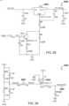
- the potentiometer 1910 is connected in parallel with the drive windings 1901, 1903, which makes it possible to compensate for the effect of poorly matched cores. The amount of current through each core can be adjusted so that the cores always saturate at the same time.
- FIG. 20 depicts two sample and hold circuits 2000 for an exemplary sense winding 2002.
- a single sample and hold integrated circuit (IC) 2004 may be very sensitive to external magnetic fields and temperature drift.
- a second sample and hold IC 2006 allows both a rising edge 2008 and a falling edge 2010 of a pulse 2012, 2014 to be sampled. The average of the rising edge 2008 and the falling edge 2010 may be fed to a proportional-integral (PI) regulator.
- PI proportional-integral
- FIG. 21 depicts a circuit 2100 of an exemplary compensation controller of a transformer.
- the PI regulator tries to cancel out the signal from the sense winding by running a current through a compensation winding 2102, the current through the compensation winding 2102 is proportional to the DC leakage current when the PI error is zero.
- the voltage across the burden resistor Rburden 2104 is therefore a direct measurement of the leakage current.
- FIG. 23 depicts a graph 2300 of a sense winding voltage 2302 and current 2304 signals caused by an external magnetic field.
- the transformer may be sensitive to external magnetic fields. External magnetic fields may have the same effect as poorly matched cores and temperature drift. External magnetic fields produce a differential signal between rising and falling edge pulses.
- FIG. 24 depicts a graph 2400 of a leakage voltage 2402 and current 2404 signals producing a common mode signal.
- the leakage signals 2402, 2404 produces a common mode signal.
- Adding a second sample and hold IC and regulating the average of the two pulses drastically reduces sensitivity to core matching, temperature drifts, and external fields.
- the differential signal caused by external fields may be tuned out using a core balance potentiometer. Dynamic control over the core balancing allows for tuning of the cores in response to changing external conditions. Tuned cores may produce less noise on the AC line and may be less susceptible to the noise on the AC line.
- Using two sampling circuits may eliminate spurious signals from core mismatch, temperature drift, and external magnetic fields.
- FIG. 26 depicts a circuit 2600 of an exemplary H-bridge driver.
- An I DriveX signal is a measurement of the drive current and may be fed to an analog comparator.
- a drive winding driver may use an off-the-shelf H-bridge.
- This circuit 2600 may not have GMI capability.
- FIG. 28 depicts a circuit 2800 of an adjustable drive voltage.
- the drive voltage for each core may be adjustable in order to compensate for core matching and drift.
- Each H bridge IC may supplied by a LM317 regulator 2802.
- the processor may reduce the output voltage of the regulator by PWM.
- the output voltage may be adjusted from 8-12V. Adjusting the output voltage may be used to adjust the drive voltage for the drive winding, using an adjustable voltage regulator to feed the H-bridge.
- FIG. 29 depicts a circuit 2900 for signal conditioning an exemplary sense winding signal.
- a sense winding is connected to a 100 ohm burden resistor 2902, which may be biased at a VCC midpoint using a resistive/capacitive divider.
- the voltage across the burden resistor 2902 may spike up to +-1V during normal operation.
- a Schottky diode 2904 protects an ADC input 2906 from abnormal spikes.
- This circuit 2900 may not have GMI functionality.
- FIG. 30 depicts an exemplary alternate transformer 3000, not according to the invention, having a window 3002 for a fluxgate.
- This transformer 3000 may not have a GMI mode.
- the transformer 3000 may have a magnetic core 3004 of a high mu material with the window 3002 for a fluxgate cut into it.
- the window 3002 goes through the entire magnetic core 3004.
- a fluxgate drive winding 3006 may saturate the left and right halves of the window at 10 kHz with opposite polarities.
- the drive winding 3006 may be present on each leg 3014, 3016 of the window 3002. There may be about twenty turns of the drive winding 3006 on each leg 3014, 3016 of the window.
- the method 3100 may then include adjusting a current to a compensation winding wound about the first and second cores to cancel out the one or more pulses on the sense winding (step 3106).
- the method 3100 may then include determining the common mode current on the one or more utility lines as the current on the compensation winding multiplied by a turn ratio between the compensation winding and the sense winding (step 3108).
- the microcontroller 3310 may drive the first drive winding of the transformer 3308 with a high frequency signal to the one or more utility lines 3314, 3316.
- the second drive winding of the transformer 3308 may measure an amplitude of a current that results, which may be proportional to a reciprocal of a ground loop impedance. wherein the high frequency signal driven by the first drive winding flows to a utility ground, to the EVSE through a ground wire, to ground filter capacitors of the EVSE and to ground filter capacitors of an electric vehicle (EV), to the second core, and to the first core. No signal may be measured by the second core if a resistance of the utility ground is too high or open.
- a minimum threshold signal measured by the second core may be set to switch off power. In some examples, the minimum threshold signal may be 0.8V, which may correspond to 150-300 ohm ground loop resistance. In other examples, the minimum threshold signal may be set to correspond to a ground loop resistance of 1500 ohm or more.
Landscapes
- Engineering & Computer Science (AREA)
- Power Engineering (AREA)
- Physics & Mathematics (AREA)
- General Physics & Mathematics (AREA)
- Transportation (AREA)
- Mechanical Engineering (AREA)
- Chemical & Material Sciences (AREA)
- Combustion & Propulsion (AREA)
- Life Sciences & Earth Sciences (AREA)
- Sustainable Development (AREA)
- Sustainable Energy (AREA)
- Electromagnetism (AREA)
- Radar, Positioning & Navigation (AREA)
- Automation & Control Theory (AREA)
- Measuring Instrument Details And Bridges, And Automatic Balancing Devices (AREA)
- Testing Of Short-Circuits, Discontinuities, Leakage, Or Incorrect Line Connections (AREA)
- Measurement Of Current Or Voltage (AREA)
Description
- Embodiments relate generally to systems, methods, and devices for safe charging, and more particularly to residual current detection (RCD) and ground monitor interrupter (GMI).
- Residual current detection (RCD) and ground monitor interrupter (GMI) are essential functions for safe charging of electric vehicles. The RCD is responsible for interrupting AC power should a conduction path to ground appear in the charging circuit. For example, a person touching live components of an electric vehicle (EV) may cause a conduction path to ground.
- The GMI ensures that the ground connection between the EV charger and a utility is continuous and of low impedance. The GMI interrupts AC power to the EV if the ground connection is noncontinuous or has high impedance. High impedance or open ground connections may result in dangerous high voltages appearing on the chassis of the EV.
- From
DE 39 40 932 A1 a measurement transducer with two soft magnetic sensor cores is known, which are acted upon by a magnetic field and has modulation coils causing opposing magnetization of the cores and a detection winding. A periodic, symmetrical modulation current is fed to the modulation coils so that the core hysteresis curves are driven well into saturation. - Zhigang Zhao et al: "The optimization of dual-core closed-loop fluxgate technology in precision current sensor", (2012), discusses a dual-core closed-loop flux gate current sensor, wherein ultra low nonlinear error and low offset error are obtained.
- From
WO 2006/048020 A1WO 2012/160233 A2 -
EP 0 137 347 A1 discloses a detector circuit for current measurements, wherein for the measurement of large currents a zero-flux current transformer is used based on two identically wound toroidal cores. FromEP 2 749 891 A1 -
US 4,274,051 discloses a line current measuring arrangement employing two matched toroidal cores with line windings, control windings, sense windings, and feedback windings. - Conventional methods for detecting residual leakage current rely on current transformers, which may be sensitive to AC leakage currents, but can saturate and fail to operate should DC leakage current be present. EV and solar installations may contain dangerously high DC voltages that may cause DC leakage current to be present.
- The invention provides a transformer according to
independent claim 1 and a method of determining a common mode current according toindependent claim 7. Advantageous embodiments are defined by the dependent claims. - In additional device embodiments, a net flux through the sense winding may be zero if no common mode current is present on the one or more utility lines. A saturation flux density of the first core may be substantially equal to the saturation flux density of the second core. A saturation flux density of the first core may be within 10% of the saturation flux density of the second core.
- The first drive winding may apply a high frequency signal to the one or more utility lines and the second drive winding may measure an amplitude of a current that results, where the amplitude of the current that results may be proportional to a reciprocal of a ground loop impedance. The common mode current in the utility line may be at least one of: an AC residual leakage current and a DC residual leakage current. The first core may be disposed substantially parallel to the second core.
- In additional method embodiments, a saturation flux density of the first core may be substantially equal to the saturation flux density of the second core. A saturation flux density of the first core may be within 10% of the saturation flux density of the second core.
- Additional method embodiments may include: measuring one or more peaks of a rising edge of the sensed one or more pulses by a first sample and hold circuit; measuring one or more peaks of a falling edge of the sensed one or more pulses by a second sample and hold circuit; determining a difference in magnitude between an average of the peaks of the rising edges and an average of the peaks of the falling edges; and adjusting at least one of: the first high frequency square wave current and the second high frequency square wave current based on the determined difference in magnitude, where the adjusted current may compensate for a difference in a saturation flux density between the first core and the second core. Method embodiments may also include: providing a high frequency signal to the one or more utility lines by the first drive winding; and measuring an amplitude of a current that results by the second drive winding, where the amplitude of the current that results may be proportional to a reciprocal of a ground loop impedance. The high frequency signal driven by the first drive winding may flow to a utility ground, to an electric vehicle service equipment (EVSE) through a ground wire, to ground filter capacitors of the EVSE and to ground filter capacitors of an electric vehicle (EV), to the second core, and to the first core. No signal may be measured by the second core if a resistance of the utility ground is too high or open. The common mode current in the utility line may be at least one of: an AC residual leakage current and a DC residual leakage current.
- The components in the figures are not necessarily to scale, emphasis instead being placed upon illustrating the principals of the invention. Like reference numerals designate corresponding parts throughout the different views. Embodiments are illustrated by way of example and not limitation in the figures of the accompanying drawings, in which:
-
FIG. 1 depicts an electrical diagram of an exemplary transformer for detecting residual leakage current; -
FIG. 2 depicts an exemplary transformer for detecting residual leakage current having two cores shown side-by-side; -
FIG. 3 depicts a graph of voltage on an exemplary sense winding and current in exemplary drive windings as cores of an exemplary transformer are driven in and out of saturation; -
FIG. 4 depicts two sample and hold circuits for an exemplary sense winding; -
FIG. 5 depicts an idealized B-H curve of two poorly matched cores of a transformer driven in unison; -
FIG. 6 depicts a graph of drive current and voltage on a sense winding for two poorly matched cores of a transformer driven in unison; -
FIG. 7 depicts a B-H curve of two well-matched cores of a transformer driven in unison; -
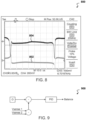
FIG. 8 depicts a graph of drive current and voltage on a sense winding for two well-matched cores of a transformer driven in unison with a DC leakage current present; -
FIG. 9 depicts an exemplary circuit for balancing two cores of a transformer with individual drive currents; -
FIG. 10 depicts a circuit of exemplary drive winding drivers; -
FIG. 11 depicts an exemplary flip flop circuit for changing polarity on a drive command signal and its inverse; -
FIG. 12 depicts a circuit of an exemplary compensation winding of a transformer; -
FIG. 13 depicts a circuit of an exemplary ground loop of an electric vehicle supply equipment (EVSE); -
FIG. 14 depicts a circuit of an exemplary ground impedance monitoring (GMI) detector; -
FIG. 15 depicts a graph of drive current, output voltage on a sense winding, and drive voltage of a transformer with well-matched cores and no current applied; -
FIG. 16 depicts a graph of drive current, output voltage on a sense winding, and drive voltage of a transformer with well-matched cores and 6mA current applied; -
FIG. 17 depicts a graph of drive current, output voltage on a sense winding, and drive voltage of a transformer with unmatched cores and no current applied; -
FIG. 18 depicts a graph of drive current, output voltage on a sense winding, and drive voltage of a transformer with unmatched cores and 6mA current applied; -
FIG. 19 depicts a circuit for generating a square wave for drive windings of a transformer; -
FIG. 20 depicts two sample and hold circuits for an exemplary sense winding; -
FIG. 21 depicts a circuit of an exemplary compensation controller of a transformer; -
FIG. 22A depicts a graph of a sensor input and output for a 60Hz sinewave; -
FIG. 22B depicts a graph of a sensor input and output for a 60Hz triangle wave; -
FIG. 22C depicts a graph of a sensor input and output for a 0.6Hz square wave; -
FIG. 23 depicts a graph of a sense winding signal caused by an external magnetic field; -
FIG. 24 depicts a graph of a leakage current producing a common mode signal; -
FIG. 25 depicts an exemplary shielding of an exemplary transformer to contain electromagnetic interference (EMI); -
FIG. 26 depicts a circuit of an exemplary H-bridge driver; -
FIG. 27 depicts a circuit of an exemplary compensation winding driver; -
FIG. 28 depicts a circuit of an adjustable drive voltage; -
FIG. 29 depicts a circuit for signal conditioning an exemplary sense winding signal; -
FIG. 30 depicts an exemplary alternate transformer having a window for a fluxgate; -
FIG. 31 depicts a flowchart of an exemplary residual current detecting (RCD) method; -
FIG. 32 depicts a flowchart of an exemplary ground monitor interrupter (GMI) method; and -
FIG. 33 depicts an exemplary system having residual current detecting (RCD) and ground monitor interrupter (GMI) to cut power between a utility and an electric vehicle if a fault is detected. - The present system allows for a DC and AC sensitive transformer for detection of residual leakage current, and associated drive circuitry, which is also able to measure the impedance of the ground connection. The system can measure leakage currents as small as 6mA with sub milliamp accuracy in the presence of charging currents as high as 80A.
-
FIG. 1 depicts an electrical diagram 100 of an exemplary transformer for detecting residual leakage current. The transformer includes two saturablemagnetic cores primary conductors 106. The transformer measures the common mode current on the one or moreprimary conductors 106. A compensation winding 108 may be wound on bothcores primary conductors 106. The transformer may also include a first drive winding 112 on thefirst core 102 and a second drive winding 114 on thesecond core 104. Thedrive windings respective cores drive windings -
FIG. 2 depicts anexemplary transformer 200, not according to the invention, for detecting residual leakage current having twocores first core 202 and asecond core 204 may be made from a square hard saturating material, such as permalloy or metglass. Thefirst core 202 and thesecond core 204 should reasonably well matched, particularly their saturation flux densities (Bmax). A first drive winding 206 is wound on thefirst core 202. A second drive winding 208 is wound on thesecond core 204. A sense winding 210 is wound across bothcores cores utility line 214 is threaded through the middle of bothcores utility line 214 may be an AC conductor of an electric vehicle supply equipment (EVSE). Thetransformer 200 may be placed about theutility line 214 between autility power source 222 and an electric vehicle (EV) 224. Themagnetic field direction 218 of thefirst core 202 and themagnetic field direction 220 of thesecond core 204 are shown with arrows. - The
cores cores first core 202 is substantially parallel to thesecond core 204. - The
transformer 200 may provide residual current detection (RCD) functionality. Each of thedrive windings cores drive currents first core 202 and thesecond core 204, but of opposite polarity. - When a common mode, or leakage, current is present in the
utility line 214, it adds to the flux in one core and subtracts from the flux in the other. This change in flux will cause one core to saturate before the other core, and the flux through the sense winding 210 no longer cancels. When one core saturates and the other doesn't saturate, the current in thedrive windings cores utility line 214. -
FIG. 3 depicts agraph 300 of voltage on an exemplary sense winding 302 and current inexemplary drive windings 304 as cores of an exemplary transformer are driven in and out of saturation. -
FIG. 4 depicts two sample and holdcircuits 400 for an exemplary sense winding. In RCD mode, the sense winding 402 is connected through aswitch 404 to aburden resistor 406 and anamplifier 408. The voltage of the peaks on the sense winding, as shown inFIG. 3 , is measured by two sample and hold (S/H)circuits drive command signal 414, as shown inFIG. 3 . The acquisition time of the S/H -
FIG. 5 depicts anidealized B-H curve 500 of two poorly matchedcores core first core 502 has a higher saturation flux density (Bsat) than thesecond core 504. Therefore, thefirst core 502 saturates later than thesecond core 504. A drive current on thefirst core 502 would couple into a sense winding of the transformer every time thecores - The disclosed transformer relies on the flux in the two cores being substantially equal, and so the cores need to be reasonably well matched, particularly their saturation flux density (Bmax). If the cores are not well matched, a spurious signal may appear on the sense winding even when there is no current flowing in the primary conductors. Temperature variation, age related drift, and external magnetic fields may cause similar spurious signals. These spurious signals must be detected and compensated for to prevent offsets in the leakage current measurement.
- The signal from mismatched cores is different from a signal from an actual current flowing on the primary. In the case of a core mismatch, the core with the lower saturation flux density (Bsat) will always saturate first regardless of drive polarity, as long as there's no current in the primary. Having one core saturate before the other will result in the drive current from the other core coupling into the sense winding every time the core saturates. Since the drive current alternates between positive and negative, this will result in pulses on the sense winding of alternating polarity.
-
FIG. 6 depicts agraph 600 of drive current 602 andvoltage 604 on a sense winding for two poorly matched cores of a transformer driven in unison. Mismatched cores, temperature drift and external magnetic fields may cause pulses of alternating polarity on the sense winding when the two cores of the transformer saturate. -
FIG. 7 depicts aB-H curve 700 of two well-matchedcores cores second core 704 saturates first and a drive current couples into the sense winding through thefirst core 702. When a negative drive current (H) is applied, thefirst core 702 saturates first and a drive current couples through thesecond core 704. Thesecond core 704 is wound with opposite polarity from thefirst core 702 so the resulting pulse on the sense winding is again positive. - For matched
cores -
FIG. 8 depicts agraph 800 of drive current 802 andvoltage 804 on a sense winding for two well-matched cores of a transformer driven in unison with a DC leakage current present. A common mode current in primary conductors results in pulses of the same polarity when the cores saturate. -
FIG. 9 depicts anexemplary circuit 900 for balancing two cores of a transformer with individual drive currents. Both cores will never be perfectly matched. Compensating for some degree of mismatching between the cores may be achieved by driving the two cores with individual drive current. The core with the lower saturation flux density (Bsat) may be driven with less current than the core with higher Bsat. By varying the current to each of the cores based on their Bsat, both cores may be made to saturate at the same time and spurious signals may be eliminated or greatly reduced. Magnetic field (H) (At/m) is a function of current, and current through an inductor is a function of the product of voltage and time (Vs). Regulating the voltage that is applied to the drive winding allows for compensating for differences in Bsat between the two cores. -
FIG. 10 depicts acircuit 1000 of exemplary drive winding drivers. A proportional-integral-derivative (PID), or similar, controller may be used to regulate out a difference in magnitude between two pulses measured by the sample and hold circuit as shown inFIG. 4 . - An output of the
balance controller 1002, as shown inFIG. 9 , may be added 1004 to the magnitude of adrive command signal 1008 of one core, and subtracted from 1006 the magnitude of adrive command signal 1010 of the other core. The drive commands 1008, 1010 may be fed throughselector switches output drive buffers drive windings resistors comparator comparator -
FIG. 11 depicts an exemplaryflip flop circuit 1100 for changing polarity on a drive command signal and its inverse. The output of the two comparators causes a flip flop circuit to change polarity on the drive command signal (Drive) and it's inverse (! Drive). -
FIG. 12 depicts acircuit 1200 of an exemplary compensation winding of a transformer. The amplitude and polarity of the pulses on a sense winding of the transformer give an indication of the common mode current flowing on primary conductors. Due to the nonlinear nature of magnetic cores, the pulses on the sense winding do not provide an accurate measurement. In order to get an accurate measurement, a compensation winding 1202 is required. The current in the compensation winding 1202 is adjusted until the pulses on the sense winding go away, which can only happen when the current in the compensation winding 1202 perfectly matches the common mode current in the primary conductors. The primary current can therefore be calculated as the current in the compensation winding multiplied by the turn ratio between the two. - A PID, or similar, controller may be used to regulate out the average voltage of the pulses on the sense winding. The output of a regulator may be used to control a current source that drives a current through the compensation winding 1202 in RCD mode. The leakage current 1204, or the common mode current, in the primary conductors may be accurately determined as the output of the regulator multiplied by the turn-ratio of the
compensation windings 1202 to the primary windings. -
FIG. 13 depicts acircuit 1300 of an exemplary ground loop of an electric vehicle supply equipment (EVSE) 1301. For safety reasons, regulatory agencies, such as UL headquartered in Northbrook, IL, requires theEVSE 1301 to verify that theEVSE 1301 and an electric vehicle (EV) 1302 are both properly grounded 1304. Theground connection 1304 betweenvehicle 1302 andEVSE 1301 may be verified by a pilot handshake signal, such as that specified in SAE J1772. Aground resistance 1306 between autility 1308 and theEVSE 1301 must however be verified by other means. - In ground monitor interrupter (GMI) mode, the fluxgate transformer may be reconfigured as a signal generator and detector. A first core of the transformer and its respective drive winding 1310 may be used to apply a high frequency signal to the
utility lines - The high frequency current generated by the first drive winding 1310 flows through the utility transformer into
ground 1304; back to the EVSE through theground wire 1318; to groundfilter capacitors EVSE 1301 andEV 1302, respectively; through the second core and back to the first core. If the resistance of the ground connection is too high, or open, no current can flow and no signal will be measured by the second core. - During the GMI test, the sense winding and compensation winding must be open circuit, which is accomplished by
selector switches -
FIG. 14 depicts acircuit 1400 of an exemplary ground impedance monitoring (GMI) detector. The second drive winding 1316 is also connected to adetector circuit 1400 throughDC blocking capacitors - An
amplifier 1406 buffers the signal from the drive winding 1316 and feeds it through abandpass filter 1408 with a center frequency around the high frequency source feeding the first drive winding 1316. The filtered signal is fed to amixer 1410, thelocal oscillator input 1412 of which is fed by a high frequency signal. Thehigh frequency signal 1412 is the same frequency as the drive, but with a different phase shift. The output of the mixer is integrated 1413 in order to measure the resulting DC signal magnitude. The output of theintegrator 1414 is now proportional to the reciprocal of the ground loop impedance. The capacitive or inductive nature of the ground impedance can be determined by adjusting the phase shift of thelocal oscillator 1412. -
FIG. 15 depicts agraph 1500 of drive current 1502,output voltage 1504 on a sense winding, and drivevoltage 1506 of a transformer with well-matched cores and no current applied. For a matched core test, a sensor was constructed from a pair of well matched cores (<0.5%). The drive winding may have 10 turns per core, the sense winding have may 10 turns, and a primary wire may be fed through the opening of both cores to measure the DC current in the primary wire. The drive winding is driven from a function generator at 10kHz through a DC blocking capacitor and a 10 ohm resistor for measuring current. Theoutput voltage 1504 is close to 0 as the flux in the two cores cancel. -
FIG. 16 depicts agraph 1600 of drive current 1602,output voltage 1604 on a sense winding, and drivevoltage 1606 of a transformer with well-matched cores and 6mA current applied. Asignificant output voltage 1604 can be seen on the sense winding when the fault current is applied, as compared to the output voltage on the sense winding with no current applied as inFIG. 15 . -
FIG. 17 depicts agraph 1700 of drive current 1702, output voltage 1704 on a sense winding, and drivevoltage 1706 of a transformer with unmatched cores and no current applied. With no DC fault current applied, the unmatched cores produce noticeably greater signal amplitude than the matched cores, as shown inFIG. 15 . The cores shown ingraph 1700 have a matching error of 10%. Ideally, the cores may have a matching error of 5% or lower, but the cores may be balanced with a matching error of up to 10%. The transformer with these unmatched cores has twenty-turn drive windings, twenty-turn sense windings, and a single turn compensation winding on only one of the cores. -
FIG. 18 depicts a graph of drive current 1802,output voltage 1804 on a sense winding, and drivevoltage 1806 of a transformer with unmatched cores and 6mA current applied. With 6mA of DC fault current applied, the unmatched transformer produces less symmetrical output for rising and falling transition than the matched sensor, as shown inFIG. 16 , but the signal amplitude remains significant. The most consistent signal component is the rapid transition of the drive current 1802 andoutput voltage 1804 around the rising edge of thedrive voltage 1806 waveform. This signal may be fully and consistently canceled by adjusting the current in the compensation winding. - In some embodiments, the transformer may be subject to variations in temperature. After being heated for five minutes, the signal remained consistent. If anything, the amplitude of the signal became more symmetrical at the rising and falling edges. The compensation current necessary to cancel the output remained consistent with no significant (<10%) drift at 6mA fault current. Both cores of the transformer tend to change temperature at the same rate due to their proximity and so any variations are largely cancelled out.
-
FIG. 19 depicts acircuit 1900 for generating a square wave fordrive windings transistors potentiometers resistors capacitors 1924. - The
drive circuit 1900 generates the square wave for thedrive windings amp 1902 used as a comparator applies a voltage to thedrive windings Rsense 1922 exceeds the trip threshold for the comparator, which then trips and reverses the output voltage. This arrangement ensures that the cores are always driven to the same level of saturation regardless of supply voltage variations or core parameters. - A
second comparator 1904 with an adjustable trip threshold is used to generate the sample pulse for the sample and hold circuit. Thesecond comparator 1904 may be adjusted to trip just before the first comparator. Thepotentiometer 1910 is connected in parallel with thedrive windings -
FIG. 20 depicts two sample and holdcircuits 2000 for an exemplary sense winding 2002. A single sample and hold integrated circuit (IC) 2004 may be very sensitive to external magnetic fields and temperature drift. A second sample and holdIC 2006 allows both a risingedge 2008 and a fallingedge 2010 of apulse edge 2008 and the fallingedge 2010 may be fed to a proportional-integral (PI) regulator. -
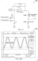
FIG. 21 depicts acircuit 2100 of an exemplary compensation controller of a transformer. The PI regulator tries to cancel out the signal from the sense winding by running a current through a compensation winding 2102, the current through the compensation winding 2102 is proportional to the DC leakage current when the PI error is zero. The voltage across theburden resistor Rburden 2104 is therefore a direct measurement of the leakage current. -
FIG. 22A depicts agraph 2200 of a sensor input 2206 and output 2208 for a 60Hz sinewave.FIG. 22B depicts agraph 2202 of asensor input 2210 andoutput 2212 for a 60Hz triangle wave.FIG. 22C depicts agraph 2204 of a sensor input 2214 and output 2216 for a 0.6Hz square wave. The transformer is able to measure up to 600Hz without significant reduction in gain, and better tuning of the PI could improve that further. -
FIG. 23 depicts agraph 2300 of asense winding voltage 2302 and current 2304 signals caused by an external magnetic field. The transformer may be sensitive to external magnetic fields. External magnetic fields may have the same effect as poorly matched cores and temperature drift. External magnetic fields produce a differential signal between rising and falling edge pulses. -
FIG. 24 depicts agraph 2400 of aleakage voltage 2402 and current 2404 signals producing a common mode signal. The leakage signals 2402, 2404 produces a common mode signal. Adding a second sample and hold IC and regulating the average of the two pulses drastically reduces sensitivity to core matching, temperature drifts, and external fields. The differential signal caused by external fields may be tuned out using a core balance potentiometer. Dynamic control over the core balancing allows for tuning of the cores in response to changing external conditions. Tuned cores may produce less noise on the AC line and may be less susceptible to the noise on the AC line. Using two sampling circuits may eliminate spurious signals from core mismatch, temperature drift, and external magnetic fields. -
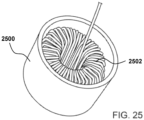
FIG. 25 depicts anexemplary shielding 2500 of anexemplary transformer 2502 to contain electromagnetic interference (EMI). Amagnetic shield 2500 made of soft iron may be placed around thetransformer 2502 to reduce and/or eliminate spurious signals caused by external magnetic fields. A cylindrical shield, such as a steel pipe, may be placed around thetransformer 2502 to reduce the effects of external magnetic fields by an order of magnitude. The shielding 2500 may also contain any EMI caused by the constant switching of the drive windings and saturating cores. Themagnetic shield 2500 greatly reduces sensitivity to external magnetic fields. -
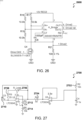
FIG. 26 depicts acircuit 2600 of an exemplary H-bridge driver. An I DriveX signal is a measurement of the drive current and may be fed to an analog comparator. A drive winding driver may use an off-the-shelf H-bridge. Thiscircuit 2600 may not have GMI capability. -
FIG. 27 depicts acircuit 2700 of an exemplary compensation winding driver. A compensation winding current may be precisely controlled, as it provides the measurement of the leakage current. Thecircuit 2700 takes a pulse width modulation (PWM) proportional to desired current where 50% = 0 current as its input. The PWM is applied toR2 2702. The filtered voltage acrossR4 2704 sets the current through theRload 2706, which is the compensation winding.R3 2708 provides a minimum impedance and improves the effect of thefilter capacitor C5 2710.R5 2712 andR6 2714 set the 0 current point.Rload 2706 is the compensation winding. Thiscircuit 2700 may not have GMI functions. -
FIG. 28 depicts acircuit 2800 of an adjustable drive voltage. The drive voltage for each core may be adjustable in order to compensate for core matching and drift. Each H bridge IC may supplied by aLM317 regulator 2802. The processor may reduce the output voltage of the regulator by PWM. The output voltage may be adjusted from 8-12V. Adjusting the output voltage may be used to adjust the drive voltage for the drive winding, using an adjustable voltage regulator to feed the H-bridge. -
FIG. 29 depicts acircuit 2900 for signal conditioning an exemplary sense winding signal. A sense winding is connected to a 100ohm burden resistor 2902, which may be biased at a VCC midpoint using a resistive/capacitive divider. The voltage across theburden resistor 2902 may spike up to +-1V during normal operation. ASchottky diode 2904 protects anADC input 2906 from abnormal spikes. Thiscircuit 2900 may not have GMI functionality. -
FIG. 30 depicts an exemplaryalternate transformer 3000, not according to the invention, having awindow 3002 for a fluxgate. Thistransformer 3000 may not have a GMI mode. Thetransformer 3000 may have amagnetic core 3004 of a high mu material with thewindow 3002 for a fluxgate cut into it. Thewindow 3002 goes through the entiremagnetic core 3004. A fluxgate drive winding 3006 may saturate the left and right halves of the window at 10 kHz with opposite polarities. The drive winding 3006 may be present on eachleg 3014, 3016 of thewindow 3002. There may be about twenty turns of the drive winding 3006 on eachleg 3014, 3016 of the window. In the presence of a magnetic field caused by DC leakage current in autility line 3008, a pulsating voltage appears on a sense winding 3010. The leakage current adds to the flux of one of the legs 3014 and subtracts from the flux of theother leg 3016, which results on a voltage on the sense winding 3010. The sense winding 3010 may be wound across both legs of themagnetic core 3004, but not through thewindow 3002. The Earth's magnetic flux may not significantly affect the reading (0.1-0.2%). This transformer is small, inexpensive, has a simple installation requiring only one turn of theutility line 3008, it is EMI immune and has low emissions, it has a high bandwidth and will measure AC leakage and DC leakage, and has a low sensitivity to external magnetic fields. - A compensation winding 3012 may be driven by a microprocessor to cancel out the voltage. Any pulses on the sense winding 3010 may be provided to a microprocessor so that they may be cancelled out by the compensation winding 3012. The microprocessor may determine a leakage current on the
utility line 3008 as the amount of compensation current needed in the compensation winding 3012 to cancel out the pulses on the sense winding 3010 is equal to the leakage current on theutility line 3008. -
FIG. 31 depicts a flowchart of an exemplary residual current detecting (RCD)method 3100. Themethod 3100 may include providing a first high frequency square wave current to a first drive winding wound on a first core (step 3102). The method may also include providing a second high frequency square wave current to a second drive winding wound on a second core (step 3104). The second high frequency square wave current may have an opposite polarity of the first high frequency square wave current. Themethod 3100 may then include sensing one or more pulses on a sense winding wound about the first and second cores (step 3106). The one or more pulses may be created by a common mode current on one or more utility lines threaded through the first and second cores. Themethod 3100 may then include adjusting a current to a compensation winding wound about the first and second cores to cancel out the one or more pulses on the sense winding (step 3106). Themethod 3100 may then include determining the common mode current on the one or more utility lines as the current on the compensation winding multiplied by a turn ratio between the compensation winding and the sense winding (step 3108). - In some embodiments, a saturation flux density of the first core may be substantially equal to the saturation flux density of the second core. In other embodiments, a saturation flux density of the first core is within 10% of the saturation flux density of the second core. If the first core has a lower saturation flux density than the second core, then the first drive winding may be provided with less current than the second drive winding such that the first core saturates at substantially the same time as the second core. One or more peaks of a rising edge of the sensed one or more pulses may be measured by a first sample and hold circuit. One or more peaks of a falling edge of the sensed one or more pulses may be measured by a second sample and hold circuit. A difference in magnitude between an average of the peaks of the rising edges and an average of the peaks of the falling edges may be determined. At least one of: the first high frequency square wave current and the second high frequency square wave current may be adjusted based on the determined difference in magnitude, and the adjusted current may compensate for a difference in a saturation flux density between the first core and the second core. The common mode current in the utility line may be at least one of: an AC residual leakage current and a DC residual leakage current.
-
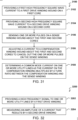
FIG. 32 depicts a flowchart of an exemplary ground monitor interrupter (GMI)method 3200. Themethod 3200 may include providing a high frequency signal to one or more utility lines by a first drive winding (step 3202). Themethod 3200 may also include measuring an amplitude of a current that results by the second drive winding (step 3204). The amplitude of the current that results may be proportional to a reciprocal of a ground loop impedance. The high frequency signal driven by the first drive winding may flow to a utility ground, to an electric vehicle service equipment (EVSE) through a ground wire, to ground filter capacitors of the EVSE and to ground filter capacitors of an electric vehicle (EV), to the second core, and to the first core. If a resistance of the utility ground is too high or open, then no signal may be measured by the second core. -
FIG. 33 depicts anexemplary system 3300, not according to the invention, having residual current detecting (RCD) and ground monitor interrupter (GMI) to cut power between autility 3302 and an electric vehicle (EV) 3304 if a fault is detected. The system may include an electric vehicle supply equipment (EVSE) 3306 to charge theEV 3304 with power provided by theutility 3302. While this system is described with reference to an EVSE, it may be applied to other electrical systems requiring RCD and GMI capabilities, such as a wall socket in a building. The EVSE may include acurrent sensing transformer 3308. The transformer may include a first core; a first drive winding wound on the first core; a second core; a second drive winding wound on the second core; a sense winding wound across the first and second cores; and a compensation winding wound across the first and second cores. The first and second cores may be arranged substantially parallel to one another. A saturation flux density of the first core may be substantially equal to the saturation flux density of the second core. One ormore utility lines EVSE 3306, may be threaded through a middle of the first and second cores of thetransformer 3308. - In RCD mode, a
microcontroller 3310 may drive the first drive winding with a first high frequency square wave current. Themicrocontroller 3310 may also drive the second drive winding with a second high frequency square wave current. The second high frequency square wave current may have an opposite polarity of the first high frequency square wave current. A common mode current, such as an AC residual leakage current and/or a DC residual leakage current, in the one ormore utility lines transformer 3308. These pulses may be detected by themicrocontroller 3310. In response to the pulses, a current on the compensation winding of thetransformer 3308 is adjusted by themicrocontroller 3310 until the one or more pulses on the sense winding of thetransformer 3308 are cancelled out. The microcontroller may determine the common mode current on the one ormore utility lines transformer 3308 multiplied by a turn ratio between the compensation winding and the sense winding of thetransformer 3308. - The
microcontroller 3310 may determine if the common mode current exceeds a set threshold. Themicrocontroller 3310 may send a signal to arelay 3312 to cut power between theEVSE 3306 and/or theEV 3304 and theutility 3302 when the determined set threshold is exceeded. The threshold may be 6mA for DC current and 20mA for AC current. The thresholds may be varied based on the application and any laws set by regulatory agencies. - In GMI mode, the
microcontroller 3310 may drive the first drive winding of thetransformer 3308 with a high frequency signal to the one ormore utility lines transformer 3308 may measure an amplitude of a current that results, which may be proportional to a reciprocal of a ground loop impedance. wherein the high frequency signal driven by the first drive winding flows to a utility ground, to the EVSE through a ground wire, to ground filter capacitors of the EVSE and to ground filter capacitors of an electric vehicle (EV), to the second core, and to the first core. No signal may be measured by the second core if a resistance of the utility ground is too high or open. A minimum threshold signal measured by the second core may be set to switch off power. In some examples, the minimum threshold signal may be 0.8V, which may correspond to 150-300 ohm ground loop resistance. In other examples, the minimum threshold signal may be set to correspond to a ground loop resistance of 1500 ohm or more. - The
EVSE 3306 may switch between RCD mode and GMI mode in order to test for both conditions. In some examples, theEVSE 3306 may switch to GMI mode four times per second for a maximum duration of 300us. To test for correct operation of the RCD mode prior to closing therelay 3312, themicrocontroller 3310 may command a current source for the compensation winding to inject a test current. In other examples, a test button may included that connects a resistor between ground and line using a switch. The response time to cut power may be varied based on the application and any regulatory requirements. The response time may be a function of the leakage current magnitude. Power may be cut on leakage current in 1ms and missing ground in 300us. However, a quicker time to cut power may create unnecessary trips due to noise. While amicrocontroller 3310 is depicted in thesystem 3300, one or all of its functions may be replaced by analog and logic circuitry in some embodiments as disclosed herein. Likewise, additional microcontrollers may be used to accomplish different functions. - It is intended that the scope of the present invention is herein disclosed by way of examples and should not be limited by the particular disclosed embodiments described above, wherein the claims shall define the matter for which protection is sought.
Claims (10)
- A transformer (100, 200) comprising:a first drive winding (112, 206) wound on a first core (102, 202), wherein the transformer (100, 200) is adapted to drive the first drive winding (112, 206) with a first high frequency square wave current (216);a second drive winding (114, 208) wound on a second core (104, 204), wherein the transformer (100, 200) is adapted to drive the second drive winding (114, 208) with a second high frequency square wave current (216), and wherein the second high frequency square wave current (216) has an opposite polarity of the first high frequency square wave current (216);a sense winding (110, 210) wound across the first and second cores (102, 104, 202, 204);a compensation winding (108, 212) wound across the first and second cores (102, 104, 202, 204); andone or more utility lines (214) that are threaded through a middle of the first and second cores (102, 104, 202, 204), wherein the utility lines (214) are adapted such that a common mode current in the one or more utility lines (214) causes one or more pulses to appear on the sense winding (110, 210), wherein the transformer (100, 200) is adapted to adjust a current on the compensation winding (108, 212) until the one or more pulses on the sense winding (110, 210) are cancelled out, and wherein the common mode current on the one or more utility lines (214) is the adjusted current on the compensation winding (108, 212) multiplied by a turn ratio between the compensation winding (108, 212) and the sense winding (110, 210),characterized in thatthe first core (102, 202) has a lower saturation flux density than the second core (104, 204), and wherein the transformer (100, 200) is configured to drive the first drive winding (112, 206) with less current than the second drive winding (114, 208) such that the first core (102, 202) saturates at substantially the same time as the second core (104, 204).
- The transformer (1 00, 200) of claim 1, wherein a net flux through the sense winding (110, 210) is zero if no common mode current is present on the one or more utility lines (214).
- The transformer (1 00, 200) of claim 1, wherein a saturation flux density of the first core (102, 202) is within 10% of the saturation flux density of the second core (104, 204).
- The transformer (1 00, 200) of claim 1, wherein the first drive winding (112, 206) is adapted to apply a high frequency signal (216) to the one or more utility lines (214), wherein the transformer (100, 200) is adapted to measure, via the second drive winding (114, 208), an amplitude of a current that results, and wherein the amplitude of the current that results is proportional to a reciprocal of a ground loop impedance.
- The transformer (1 00, 200) of claim 1, wherein the common mode current in the utility line (214) is at least one of: an AC residual leakage current and a DC residual leakage current.
- The transformer (1 00, 200) of claim 1, wherein the first core (102, 202) is disposed substantially parallel to the second core (104, 204).
- A method (3100) comprising:providing a first high frequency square wave current to a first drive winding wound on a first core (3102);providing a second high frequency square wave current to a second drive winding wound on a second core (3104), wherein the second high frequency square wave current has an opposite polarity of the first high frequency square wave current;sensing one or more pulses on a sense winding wound about the first and second cores (3106), wherein the one or more pulses are created by a common mode current on one or more utility lines threaded through the first and second cores;adjusting a current to a compensation winding wound about the first and second cores to cancel out the one or more pulses on the sense winding (3106);determining the common mode current on the one or more utility lines as the current on the compensation winding multiplied by a turn ratio between the compensation winding and the sense winding (3108),characterized in thatthe first core has a lower saturation flux density than the second core and wherein the first drive winding is driven with less current than the second drive winding such that the first core saturates at substantially the same time as the second core.
- The method (3100) of claim 7, wherein a saturation flux density of the first core is within 10% of the saturation flux density of the second core, or
wherein the method (3100, 3200) further comprises:providing a high frequency signal to the one or more utility lines by the first drive winding (3202); andmeasuring an amplitude of a current that results by the second drive winding (3204), wherein the amplitude of the current that results is proportional to a reciprocal of a ground loop impedance, orwherein the common mode current in the utility line is at least one of: an AC residual leakage current and a DC residual leakage current. - The method of claim 8,
wherein the method further comprises:measuring one or more peaks of a rising edge of the sensed one or more pulses by a first sample and hold circuit;measuring one or more peaks of a falling edge of the sensed one or more pulses by a second sample and hold circuit;determining a difference in magnitude between an average of the peaks of the rising edges and an average of the peaks of the falling edges; andadjusting at least one of: the first high frequency square wave current and the second high frequency square wave current based on the determined difference in magnitude, wherein the adjusted current compensates for a difference in a saturation flux density between the first core and the second core. - The method of claim 8, wherein a high frequency signal is provided to the one or more utility lines by the first drive winding and wherein an amplitude of a current that results by the second drive winding is measured, wherein the amplitude of the current that results is proportional to a reciprocal of a ground loop impedance, wherein the high frequency signal driven by the first drive winding flows to a utility ground, to an electric vehicle service equipment (EVSE) through a ground wire, to ground filter capacitors of the EVSE and to ground filter capacitors of an electric vehicle (EV), to the second core, and to the first core, preferably, wherein no signal is measured by the second core if a resistance of the utility ground is too high or open.
Applications Claiming Priority (2)
| Application Number | Priority Date | Filing Date | Title |
|---|---|---|---|
| US201662346287P | 2016-06-06 | 2016-06-06 | |
| PCT/US2017/035951 WO2017214035A1 (en) | 2016-06-06 | 2017-06-05 | Residual current detecting (rcd) and ground impedance monitoring transformer and control methods |
Publications (3)
| Publication Number | Publication Date |
|---|---|
| EP3465867A1 EP3465867A1 (en) | 2019-04-10 |
| EP3465867A4 EP3465867A4 (en) | 2020-01-22 |
| EP3465867B1 true EP3465867B1 (en) | 2023-05-24 |
Family
ID=60482187
Family Applications (1)
| Application Number | Title | Priority Date | Filing Date |
|---|---|---|---|
| EP17810786.8A Active EP3465867B1 (en) | 2016-06-06 | 2017-06-05 | Transformer for measuring a common mode current and method of determining a common mode current |
Country Status (4)
| Country | Link |
|---|---|
| US (2) | US9964574B2 (en) |
| EP (1) | EP3465867B1 (en) |
| CN (2) | CN114035114B (en) |
| WO (1) | WO2017214035A1 (en) |
Families Citing this family (17)
| Publication number | Priority date | Publication date | Assignee | Title |
|---|---|---|---|---|
| CN114035114B (en) * | 2016-06-06 | 2024-11-26 | 韦巴斯托充电系统公司 | Residual current detection (RCD) and ground impedance monitoring transformer and control method |
| GB2568963B (en) * | 2017-12-04 | 2022-06-22 | Eaton Intelligent Power Ltd | Voltage transformer |
| CN109470929A (en) * | 2018-10-18 | 2019-03-15 | 天津天禹水务工程勘察设计有限公司 | Real-time earthing lightning protection monitoring system and monitoring method based on Internet of Things |
| GB2578339B (en) | 2019-03-25 | 2020-12-30 | Greentec International Ltd | Open PEN detection and shut down system |
| CN112242723B (en) * | 2019-07-16 | 2025-05-30 | 中核检修有限公司 | Relay testing device and tester |
| CN110672913B (en) * | 2019-10-09 | 2022-06-21 | 青岛鼎信通讯股份有限公司 | Complex waveform signal processing method suitable for alternating current and direct current leakage detection |
| DE102019007224B3 (en) * | 2019-10-17 | 2021-03-25 | SAFETYTEST GmbH | Method and device for determining the resistive component of the leakage current impedance in the alternating current network |
| CN111812456B (en) * | 2020-07-02 | 2022-10-21 | 国网江苏省电力有限公司检修分公司 | Power transmission line fault positioning method, device and system |
| TWI760185B (en) * | 2021-04-14 | 2022-04-01 | 愛盛科技股份有限公司 | Leakage current detection circuit and fluxgate driver |
| CN112881945B (en) * | 2021-04-21 | 2022-10-14 | 深圳市市政设计研究院有限公司 | Method and device for judging ground fault |
| CN113363951B (en) * | 2021-05-21 | 2023-10-31 | 珠海格力电器股份有限公司 | Direct current residual current protector, protection method and direct current power supply system |
| CN113552401A (en) * | 2021-07-07 | 2021-10-26 | 国电南瑞科技股份有限公司 | High-frequency current sensor adopting auxiliary winding degaussing and discharge current detection method |
| WO2023107739A1 (en) * | 2021-12-10 | 2023-06-15 | Vertiv Corporation | Residual current monitoring type b with integrated self-test system and method |
| US12196784B1 (en) * | 2022-01-18 | 2025-01-14 | National Technology & Engineering Solutions Of Sandia, Llc | Magnetostrictive current sensor method and system |
| CN115616438A (en) * | 2022-08-01 | 2023-01-17 | 安徽橡豫智能科技有限公司 | Low-cost A-type residual current detection method integrated on common-mode inductor |
| US12169226B2 (en) * | 2022-09-01 | 2024-12-17 | Webasto Charging Systems, Inc. | Digital residual current detecting system |
| CN222561751U (en) * | 2023-12-12 | 2025-03-04 | 施耐德电气(中国)有限公司 | Leakage current detection circuit and leakage current protection circuit |
Family Cites Families (29)
| Publication number | Priority date | Publication date | Assignee | Title |
|---|---|---|---|---|
| US3500171A (en) * | 1967-01-06 | 1970-03-10 | Canadian Patents Dev | Self-balancing current comparator for precise voltage levels and potentiometer usage |
| US4278940A (en) * | 1979-04-25 | 1981-07-14 | General Electric Company | Means for automatically compensating DC magnetization in a transformer |
| US4262259A (en) * | 1979-06-22 | 1981-04-14 | Nasa | Low current linearization of magnetic amplifier for DC transducer |
| US4274051A (en) * | 1979-07-27 | 1981-06-16 | Bell Telephone Laboratories, Incorporated | Electromagnetic arrangement for measuring electrical current |
| DK149238C (en) | 1983-09-15 | 1987-01-19 | Danfysik As | DETECTOR CIRCUIT FOR USE IN POWER METERING |
| US4742294A (en) * | 1986-07-16 | 1988-05-03 | Venus Scientific Inc. | Helix current sense system |
| DE3940932A1 (en) | 1989-12-12 | 1991-06-13 | Ulrich Doerr | Measurement transducer for simultaneous measurement of AC and DC - has two soft magnetic cores, modulation coils and detection coil and uses periodic modulation current |
| US5327065A (en) | 1992-01-22 | 1994-07-05 | Hughes Aircraft Company | Hand-held inductive charger having concentric windings |
| CN1641365A (en) * | 2004-01-16 | 2005-07-20 | 中国科学院上海应用物理研究所 | Zero-flux current sensor circuit |
| EP1807707B1 (en) | 2004-11-05 | 2010-09-22 | Liaisons Electroniques-Mècaniques LEM S.A. | Detector circuit for measuring current |
| US7911808B2 (en) * | 2007-02-10 | 2011-03-22 | Active-Semi, Inc. | Primary side constant output current controller with highly improved accuracy |
| US8896315B1 (en) * | 2009-02-12 | 2014-11-25 | The United States Of America As Represented By The Administrator Of The National Aeronautics And Space Administration | Battery cell balancing system and method |
| JP2011017618A (en) * | 2009-07-09 | 2011-01-27 | Tamura Seisakusho Co Ltd | Electric current sensor |
| CN102480239A (en) * | 2010-11-29 | 2012-05-30 | 技领半导体(上海)有限公司 | Power converter and method for realizing constant voltage of output terminal |
| US8704481B2 (en) * | 2011-01-26 | 2014-04-22 | Rockwell Automation Technologies, Inc. | Choke with current sensor |
| DK2515123T3 (en) * | 2011-04-21 | 2016-10-31 | Abb Ag | Current sensor that works according to the compensation principle |
| ES2392304B9 (en) | 2011-05-23 | 2013-12-18 | Premo, S.L. | CHARGER AND PROCEDURE FOR THE MEASUREMENT OF THE LOADING CURRENT FOR ELECTRIC VEHICLES. |
| CN102401853B (en) * | 2011-11-28 | 2013-09-04 | 河北工业大学 | Double-shaft fluxgate current sensor |
| JP2013124875A (en) | 2011-12-13 | 2013-06-24 | Japan Aviation Electronics Industry Ltd | Current sensor |
| FR2987515B1 (en) * | 2012-02-29 | 2015-01-23 | Valeo Sys Controle Moteur Sas | DEVICE FOR DETECTING A LEAKAGE CURRENT COMPRISING A CONTINUOUS COMPONENT, ONBOARD IN A VEHICLE, AND APPLICATIONS OF SAID DEVICE |
| US9093941B2 (en) * | 2012-05-25 | 2015-07-28 | Cirrus Logic, Inc. | Determining commutation position for a sensorless permanent magnet brushless motor at low or zero speed using an asymmetric drive pattern |
| US9088237B2 (en) * | 2012-05-25 | 2015-07-21 | Cirrus Logic, Inc. | Circuit and method for calibration of sensorless control of a permanent magnet brushless motor during start-up |
| US8994306B2 (en) * | 2012-05-25 | 2015-03-31 | Cirrus Logic, Inc. | System and method for isolating the undriven voltage of a permanent magnet brushless motor for detection of rotor position |
| JP2014023408A (en) * | 2012-07-24 | 2014-02-03 | Murata Mfg Co Ltd | Power receiving device power transmission system |
| JP6304647B2 (en) * | 2012-11-21 | 2018-04-04 | パナソニックIpマネジメント株式会社 | Current detector |
| CN103401442B (en) * | 2013-07-30 | 2015-09-02 | 浙江大学 | A kind of digitial controller of the AC-DC isolated converter based on output constant current |
| CN104931758B (en) * | 2014-03-21 | 2018-03-27 | 上海电科电器科技有限公司 | Direct current residual current detection device |
| CN204044236U (en) * | 2014-08-20 | 2014-12-24 | 上海正泰电源系统有限公司 | A kind of leakage current detection circuit |
| CN114035114B (en) * | 2016-06-06 | 2024-11-26 | 韦巴斯托充电系统公司 | Residual current detection (RCD) and ground impedance monitoring transformer and control method |
-
2017
- 2017-06-05 CN CN202111340011.0A patent/CN114035114B/en active Active
- 2017-06-05 WO PCT/US2017/035951 patent/WO2017214035A1/en not_active Ceased
- 2017-06-05 CN CN201780035123.0A patent/CN109463031A/en active Pending
- 2017-06-05 US US15/614,059 patent/US9964574B2/en active Active
- 2017-06-05 EP EP17810786.8A patent/EP3465867B1/en active Active
-
2018
- 2018-04-06 US US15/947,322 patent/US10585127B2/en active Active
Also Published As
| Publication number | Publication date |
|---|---|
| EP3465867A1 (en) | 2019-04-10 |
| CN109463031A (en) | 2019-03-12 |
| US9964574B2 (en) | 2018-05-08 |
| EP3465867A4 (en) | 2020-01-22 |
| CN114035114B (en) | 2024-11-26 |
| US20170350927A1 (en) | 2017-12-07 |
| US20180224488A1 (en) | 2018-08-09 |
| WO2017214035A1 (en) | 2017-12-14 |
| CN114035114A (en) | 2022-02-11 |
| US10585127B2 (en) | 2020-03-10 |
Similar Documents
| Publication | Publication Date | Title |
|---|---|---|
| US10585127B2 (en) | Residual current detecting (RCD) and ground impedance monitoring transformer and control methods | |
| EP2924450B1 (en) | Current detecting device | |
| CN102866283B (en) | Superimposed large-current bias alternative-current (AC) current measuring device | |
| EP3531145B1 (en) | Electricity leakage detection device | |
| US9846181B2 (en) | Flux-gate current sensor with additional frequency measuring | |
| DE3708892C2 (en) | Current measuring device, in particular for determining the motor current of a DC motor | |
| US8102629B2 (en) | Leakage current compensation for high voltage transformers | |
| US10983174B2 (en) | Direct-current electricity leakage detection device and electricity leakage detection device | |
| US20150160271A1 (en) | Current detection device | |
| CN104221237A (en) | Detection of Leakage Current Including DC Component in Vehicles | |
| CN109946497B (en) | Current sensor device and contactless current measuring method | |
| CA2959373C (en) | Apparatus, method and device for sensing dc currents | |
| DE4230939A1 (en) | Circuitry changing or compensating electrical properties of current converter with magnetic field compensation - contains prim., sec. and measurement coils on core, Hall element in air gap feeding compensation current source controller | |
| DE112005001167B4 (en) | Residual current detection | |
| US20180196087A1 (en) | Device for measuring a magnetic field | |
| CN202837368U (en) | AC measuring device superposed large DC bias | |
| US20160103155A1 (en) | Current Sensor | |
| CN113514689A (en) | Device and method for measuring electrically insulated, AC/DC sensitive differential current | |
| CA2766758A1 (en) | Active core current sensor | |
| DE102010042512B4 (en) | Inductive proximity switch with reduced temperature dependence | |
| WO2020136545A1 (en) | Method and device for monitoring operation of a switching device for controlled switching applications | |
| KR102863300B1 (en) | Fluxgate DC current sensor with improved precision through current measurement scale adjustment | |
| EP3842812B1 (en) | Measuring apparatus for measuring a dc component of an electric current and associated measuring method | |
| US12601764B2 (en) | Electric circuit arrangement and method for the galvanically separate, AC/DC-sensitive residual-current measurement | |
| DE102010042511B4 (en) | Inductive proximity switch with reduced temperature dependence |
Legal Events
| Date | Code | Title | Description |
|---|---|---|---|
| STAA | Information on the status of an ep patent application or granted ep patent |
Free format text: STATUS: THE INTERNATIONAL PUBLICATION HAS BEEN MADE |
|
| PUAI | Public reference made under article 153(3) epc to a published international application that has entered the european phase |
Free format text: ORIGINAL CODE: 0009012 |
|
| STAA | Information on the status of an ep patent application or granted ep patent |
Free format text: STATUS: REQUEST FOR EXAMINATION WAS MADE |
|
| 17P | Request for examination filed |
Effective date: 20181221 |
|
| AK | Designated contracting states |
Kind code of ref document: A1 Designated state(s): AL AT BE BG CH CY CZ DE DK EE ES FI FR GB GR HR HU IE IS IT LI LT LU LV MC MK MT NL NO PL PT RO RS SE SI SK SM TR |
|
| AX | Request for extension of the european patent |
Extension state: BA ME |
|
| DAV | Request for validation of the european patent (deleted) | ||
| DAX | Request for extension of the european patent (deleted) | ||
| A4 | Supplementary search report drawn up and despatched |
Effective date: 20200107 |
|
| RIC1 | Information provided on ipc code assigned before grant |
Ipc: H02H 3/33 20060101AFI20191219BHEP Ipc: G01R 31/00 20060101ALI20191219BHEP Ipc: B60L 3/00 20190101ALI20191219BHEP Ipc: G01R 27/18 20060101ALN20191219BHEP Ipc: G01R 15/18 20060101ALI20191219BHEP Ipc: B60L 53/60 20190101ALN20191219BHEP Ipc: G01R 31/02 20060101ALN20191219BHEP |
|
| REG | Reference to a national code |
Ref country code: DE Ref legal event code: R079 Ref document number: 602017069040 Country of ref document: DE Free format text: PREVIOUS MAIN CLASS: H02J0007140000 Ipc: G01R0015180000 |
|
| GRAP | Despatch of communication of intention to grant a patent |
Free format text: ORIGINAL CODE: EPIDOSNIGR1 |
|
| STAA | Information on the status of an ep patent application or granted ep patent |
Free format text: STATUS: GRANT OF PATENT IS INTENDED |
|
| RIC1 | Information provided on ipc code assigned before grant |
Ipc: G01R 31/52 20200101ALN20221114BHEP Ipc: G01R 19/10 20060101ALN20221114BHEP Ipc: G01R 27/18 20060101ALN20221114BHEP Ipc: B60L 53/60 20190101ALN20221114BHEP Ipc: B60L 53/50 20190101ALI20221114BHEP Ipc: B60L 53/00 20190101ALI20221114BHEP Ipc: B60L 53/66 20190101ALI20221114BHEP Ipc: B60L 3/00 20190101ALI20221114BHEP Ipc: H02H 3/33 20060101ALI20221114BHEP Ipc: G01R 31/00 20060101ALI20221114BHEP Ipc: G01R 15/18 20060101AFI20221114BHEP |
|
| INTG | Intention to grant announced |
Effective date: 20221215 |
|
| GRAS | Grant fee paid |
Free format text: ORIGINAL CODE: EPIDOSNIGR3 |
|
| GRAA | (expected) grant |
Free format text: ORIGINAL CODE: 0009210 |
|
| STAA | Information on the status of an ep patent application or granted ep patent |
Free format text: STATUS: THE PATENT HAS BEEN GRANTED |
|
| AK | Designated contracting states |
Kind code of ref document: B1 Designated state(s): AL AT BE BG CH CY CZ DE DK EE ES FI FR GB GR HR HU IE IS IT LI LT LU LV MC MK MT NL NO PL PT RO RS SE SI SK SM TR |
|
| REG | Reference to a national code |
Ref country code: GB Ref legal event code: FG4D |
|
| REG | Reference to a national code |
Ref country code: CH Ref legal event code: EP |
|
| REG | Reference to a national code |
Ref country code: DE Ref legal event code: R096 Ref document number: 602017069040 Country of ref document: DE |
|
| REG | Reference to a national code |
Ref country code: AT Ref legal event code: REF Ref document number: 1569829 Country of ref document: AT Kind code of ref document: T Effective date: 20230615 |
|
| REG | Reference to a national code |
Ref country code: IE Ref legal event code: FG4D |
|
| REG | Reference to a national code |
Ref country code: LT Ref legal event code: MG9D |
|
| REG | Reference to a national code |
Ref country code: NL Ref legal event code: MP Effective date: 20230524 |
|
| REG | Reference to a national code |
Ref country code: AT Ref legal event code: MK05 Ref document number: 1569829 Country of ref document: AT Kind code of ref document: T Effective date: 20230524 |
|
| PG25 | Lapsed in a contracting state [announced via postgrant information from national office to epo] |
Ref country code: SE Free format text: LAPSE BECAUSE OF FAILURE TO SUBMIT A TRANSLATION OF THE DESCRIPTION OR TO PAY THE FEE WITHIN THE PRESCRIBED TIME-LIMIT Effective date: 20230524 Ref country code: PT Free format text: LAPSE BECAUSE OF FAILURE TO SUBMIT A TRANSLATION OF THE DESCRIPTION OR TO PAY THE FEE WITHIN THE PRESCRIBED TIME-LIMIT Effective date: 20230925 Ref country code: NO Free format text: LAPSE BECAUSE OF FAILURE TO SUBMIT A TRANSLATION OF THE DESCRIPTION OR TO PAY THE FEE WITHIN THE PRESCRIBED TIME-LIMIT Effective date: 20230824 Ref country code: NL Free format text: LAPSE BECAUSE OF FAILURE TO SUBMIT A TRANSLATION OF THE DESCRIPTION OR TO PAY THE FEE WITHIN THE PRESCRIBED TIME-LIMIT Effective date: 20230524 Ref country code: ES Free format text: LAPSE BECAUSE OF FAILURE TO SUBMIT A TRANSLATION OF THE DESCRIPTION OR TO PAY THE FEE WITHIN THE PRESCRIBED TIME-LIMIT Effective date: 20230524 Ref country code: AT Free format text: LAPSE BECAUSE OF FAILURE TO SUBMIT A TRANSLATION OF THE DESCRIPTION OR TO PAY THE FEE WITHIN THE PRESCRIBED TIME-LIMIT Effective date: 20230524 |
|
| PG25 | Lapsed in a contracting state [announced via postgrant information from national office to epo] |
Ref country code: RS Free format text: LAPSE BECAUSE OF FAILURE TO SUBMIT A TRANSLATION OF THE DESCRIPTION OR TO PAY THE FEE WITHIN THE PRESCRIBED TIME-LIMIT Effective date: 20230524 Ref country code: PL Free format text: LAPSE BECAUSE OF FAILURE TO SUBMIT A TRANSLATION OF THE DESCRIPTION OR TO PAY THE FEE WITHIN THE PRESCRIBED TIME-LIMIT Effective date: 20230524 Ref country code: LV Free format text: LAPSE BECAUSE OF FAILURE TO SUBMIT A TRANSLATION OF THE DESCRIPTION OR TO PAY THE FEE WITHIN THE PRESCRIBED TIME-LIMIT Effective date: 20230524 Ref country code: LT Free format text: LAPSE BECAUSE OF FAILURE TO SUBMIT A TRANSLATION OF THE DESCRIPTION OR TO PAY THE FEE WITHIN THE PRESCRIBED TIME-LIMIT Effective date: 20230524 Ref country code: IS Free format text: LAPSE BECAUSE OF FAILURE TO SUBMIT A TRANSLATION OF THE DESCRIPTION OR TO PAY THE FEE WITHIN THE PRESCRIBED TIME-LIMIT Effective date: 20230924 Ref country code: HR Free format text: LAPSE BECAUSE OF FAILURE TO SUBMIT A TRANSLATION OF THE DESCRIPTION OR TO PAY THE FEE WITHIN THE PRESCRIBED TIME-LIMIT Effective date: 20230524 Ref country code: GR Free format text: LAPSE BECAUSE OF FAILURE TO SUBMIT A TRANSLATION OF THE DESCRIPTION OR TO PAY THE FEE WITHIN THE PRESCRIBED TIME-LIMIT Effective date: 20230825 |
|
| PG25 | Lapsed in a contracting state [announced via postgrant information from national office to epo] |
Ref country code: FI Free format text: LAPSE BECAUSE OF FAILURE TO SUBMIT A TRANSLATION OF THE DESCRIPTION OR TO PAY THE FEE WITHIN THE PRESCRIBED TIME-LIMIT Effective date: 20230524 |
|
| PG25 | Lapsed in a contracting state [announced via postgrant information from national office to epo] |
Ref country code: SK Free format text: LAPSE BECAUSE OF FAILURE TO SUBMIT A TRANSLATION OF THE DESCRIPTION OR TO PAY THE FEE WITHIN THE PRESCRIBED TIME-LIMIT Effective date: 20230524 |
|
| PG25 | Lapsed in a contracting state [announced via postgrant information from national office to epo] |
Ref country code: SM Free format text: LAPSE BECAUSE OF FAILURE TO SUBMIT A TRANSLATION OF THE DESCRIPTION OR TO PAY THE FEE WITHIN THE PRESCRIBED TIME-LIMIT Effective date: 20230524 Ref country code: SK Free format text: LAPSE BECAUSE OF FAILURE TO SUBMIT A TRANSLATION OF THE DESCRIPTION OR TO PAY THE FEE WITHIN THE PRESCRIBED TIME-LIMIT Effective date: 20230524 Ref country code: RO Free format text: LAPSE BECAUSE OF FAILURE TO SUBMIT A TRANSLATION OF THE DESCRIPTION OR TO PAY THE FEE WITHIN THE PRESCRIBED TIME-LIMIT Effective date: 20230524 Ref country code: EE Free format text: LAPSE BECAUSE OF FAILURE TO SUBMIT A TRANSLATION OF THE DESCRIPTION OR TO PAY THE FEE WITHIN THE PRESCRIBED TIME-LIMIT Effective date: 20230524 Ref country code: DK Free format text: LAPSE BECAUSE OF FAILURE TO SUBMIT A TRANSLATION OF THE DESCRIPTION OR TO PAY THE FEE WITHIN THE PRESCRIBED TIME-LIMIT Effective date: 20230524 Ref country code: CZ Free format text: LAPSE BECAUSE OF FAILURE TO SUBMIT A TRANSLATION OF THE DESCRIPTION OR TO PAY THE FEE WITHIN THE PRESCRIBED TIME-LIMIT Effective date: 20230524 |
|
| REG | Reference to a national code |
Ref country code: CH Ref legal event code: PL |
|
| REG | Reference to a national code |
Ref country code: BE Ref legal event code: MM Effective date: 20230630 |
|
| REG | Reference to a national code |
Ref country code: DE Ref legal event code: R097 Ref document number: 602017069040 Country of ref document: DE |
|
| PG25 | Lapsed in a contracting state [announced via postgrant information from national office to epo] |
Ref country code: MC Free format text: LAPSE BECAUSE OF FAILURE TO SUBMIT A TRANSLATION OF THE DESCRIPTION OR TO PAY THE FEE WITHIN THE PRESCRIBED TIME-LIMIT Effective date: 20230524 |
|
| PG25 | Lapsed in a contracting state [announced via postgrant information from national office to epo] |
Ref country code: MC Free format text: LAPSE BECAUSE OF FAILURE TO SUBMIT A TRANSLATION OF THE DESCRIPTION OR TO PAY THE FEE WITHIN THE PRESCRIBED TIME-LIMIT Effective date: 20230524 |
|
| PG25 | Lapsed in a contracting state [announced via postgrant information from national office to epo] |
Ref country code: LU Free format text: LAPSE BECAUSE OF NON-PAYMENT OF DUE FEES Effective date: 20230605 |
|
| REG | Reference to a national code |
Ref country code: IE Ref legal event code: MM4A |
|
| PG25 | Lapsed in a contracting state [announced via postgrant information from national office to epo] |
Ref country code: LU Free format text: LAPSE BECAUSE OF NON-PAYMENT OF DUE FEES Effective date: 20230605 |
|
| PLBE | No opposition filed within time limit |
Free format text: ORIGINAL CODE: 0009261 |
|
| STAA | Information on the status of an ep patent application or granted ep patent |
Free format text: STATUS: NO OPPOSITION FILED WITHIN TIME LIMIT |
|
| PG25 | Lapsed in a contracting state [announced via postgrant information from national office to epo] |
Ref country code: IE Free format text: LAPSE BECAUSE OF NON-PAYMENT OF DUE FEES Effective date: 20230605 |
|
| PG25 | Lapsed in a contracting state [announced via postgrant information from national office to epo] |
Ref country code: IE Free format text: LAPSE BECAUSE OF NON-PAYMENT OF DUE FEES Effective date: 20230605 Ref country code: CH Free format text: LAPSE BECAUSE OF NON-PAYMENT OF DUE FEES Effective date: 20230630 |
|
| 26N | No opposition filed |
Effective date: 20240227 |
|
| PG25 | Lapsed in a contracting state [announced via postgrant information from national office to epo] |
Ref country code: SI Free format text: LAPSE BECAUSE OF FAILURE TO SUBMIT A TRANSLATION OF THE DESCRIPTION OR TO PAY THE FEE WITHIN THE PRESCRIBED TIME-LIMIT Effective date: 20230524 |
|
| PG25 | Lapsed in a contracting state [announced via postgrant information from national office to epo] |
Ref country code: SI Free format text: LAPSE BECAUSE OF FAILURE TO SUBMIT A TRANSLATION OF THE DESCRIPTION OR TO PAY THE FEE WITHIN THE PRESCRIBED TIME-LIMIT Effective date: 20230524 Ref country code: IT Free format text: LAPSE BECAUSE OF FAILURE TO SUBMIT A TRANSLATION OF THE DESCRIPTION OR TO PAY THE FEE WITHIN THE PRESCRIBED TIME-LIMIT Effective date: 20230524 Ref country code: BE Free format text: LAPSE BECAUSE OF NON-PAYMENT OF DUE FEES Effective date: 20230630 |
|
| PG25 | Lapsed in a contracting state [announced via postgrant information from national office to epo] |
Ref country code: BG Free format text: LAPSE BECAUSE OF FAILURE TO SUBMIT A TRANSLATION OF THE DESCRIPTION OR TO PAY THE FEE WITHIN THE PRESCRIBED TIME-LIMIT Effective date: 20230524 |
|
| PG25 | Lapsed in a contracting state [announced via postgrant information from national office to epo] |
Ref country code: BG Free format text: LAPSE BECAUSE OF FAILURE TO SUBMIT A TRANSLATION OF THE DESCRIPTION OR TO PAY THE FEE WITHIN THE PRESCRIBED TIME-LIMIT Effective date: 20230524 |
|
| REG | Reference to a national code |
Ref country code: DE Ref legal event code: R082 Ref document number: 602017069040 Country of ref document: DE Representative=s name: MAUCHER JENKINS PATENTANWAELTE & RECHTSANWAELT, DE Ref country code: DE Ref legal event code: R082 Ref document number: 602017069040 Country of ref document: DE Representative=s name: DEHNS PATENT AND TRADEMARK ATTORNEYS, DE |
|
| PGFP | Annual fee paid to national office [announced via postgrant information from national office to epo] |
Ref country code: GB Payment date: 20250620 Year of fee payment: 9 |
|
| PGFP | Annual fee paid to national office [announced via postgrant information from national office to epo] |
Ref country code: FR Payment date: 20250618 Year of fee payment: 9 |
|
| PG25 | Lapsed in a contracting state [announced via postgrant information from national office to epo] |
Ref country code: CY Free format text: LAPSE BECAUSE OF FAILURE TO SUBMIT A TRANSLATION OF THE DESCRIPTION OR TO PAY THE FEE WITHIN THE PRESCRIBED TIME-LIMIT; INVALID AB INITIO Effective date: 20170605 |
|
| PG25 | Lapsed in a contracting state [announced via postgrant information from national office to epo] |
Ref country code: HU Free format text: LAPSE BECAUSE OF FAILURE TO SUBMIT A TRANSLATION OF THE DESCRIPTION OR TO PAY THE FEE WITHIN THE PRESCRIBED TIME-LIMIT; INVALID AB INITIO Effective date: 20170605 |
|
| REG | Reference to a national code |
Ref country code: DE Ref legal event code: R082 Ref document number: 602017069040 Country of ref document: DE Representative=s name: DEHNS PATENT AND TRADEMARK ATTORNEYS, DE |
|
| PGFP | Annual fee paid to national office [announced via postgrant information from national office to epo] |
Ref country code: DE Payment date: 20250701 Year of fee payment: 9 |
|
| PG25 | Lapsed in a contracting state [announced via postgrant information from national office to epo] |
Ref country code: TR Free format text: LAPSE BECAUSE OF FAILURE TO SUBMIT A TRANSLATION OF THE DESCRIPTION OR TO PAY THE FEE WITHIN THE PRESCRIBED TIME-LIMIT Effective date: 20230524 |