EP3465049B1 - Counter-flow heat exchanger - Google Patents
Counter-flow heat exchanger Download PDFInfo
- Publication number
- EP3465049B1 EP3465049B1 EP17807598.2A EP17807598A EP3465049B1 EP 3465049 B1 EP3465049 B1 EP 3465049B1 EP 17807598 A EP17807598 A EP 17807598A EP 3465049 B1 EP3465049 B1 EP 3465049B1
- Authority
- EP
- European Patent Office
- Prior art keywords
- plate
- plenum
- plate assembly
- heat exchanger
- baffle
- Prior art date
- Legal status (The legal status is an assumption and is not a legal conclusion. Google has not performed a legal analysis and makes no representation as to the accuracy of the status listed.)
- Active
Links
Images







Classifications
-
- F—MECHANICAL ENGINEERING; LIGHTING; HEATING; WEAPONS; BLASTING
- F28—HEAT EXCHANGE IN GENERAL
- F28D—HEAT-EXCHANGE APPARATUS, NOT PROVIDED FOR IN ANOTHER SUBCLASS, IN WHICH THE HEAT-EXCHANGE MEDIA DO NOT COME INTO DIRECT CONTACT
- F28D9/00—Heat-exchange apparatus having stationary plate-like or laminated conduit assemblies for both heat-exchange media, the media being in contact with different sides of a conduit wall
- F28D9/0006—Heat-exchange apparatus having stationary plate-like or laminated conduit assemblies for both heat-exchange media, the media being in contact with different sides of a conduit wall the plate-like or laminated conduits being enclosed within a pressure vessel
-
- F—MECHANICAL ENGINEERING; LIGHTING; HEATING; WEAPONS; BLASTING
- F28—HEAT EXCHANGE IN GENERAL
- F28D—HEAT-EXCHANGE APPARATUS, NOT PROVIDED FOR IN ANOTHER SUBCLASS, IN WHICH THE HEAT-EXCHANGE MEDIA DO NOT COME INTO DIRECT CONTACT
- F28D21/00—Heat-exchange apparatus not covered by any of the groups F28D1/00 - F28D20/00
- F28D21/0001—Recuperative heat exchangers
- F28D21/0003—Recuperative heat exchangers the heat being recuperated from exhaust gases
-
- F—MECHANICAL ENGINEERING; LIGHTING; HEATING; WEAPONS; BLASTING
- F28—HEAT EXCHANGE IN GENERAL
- F28D—HEAT-EXCHANGE APPARATUS, NOT PROVIDED FOR IN ANOTHER SUBCLASS, IN WHICH THE HEAT-EXCHANGE MEDIA DO NOT COME INTO DIRECT CONTACT
- F28D9/00—Heat-exchange apparatus having stationary plate-like or laminated conduit assemblies for both heat-exchange media, the media being in contact with different sides of a conduit wall
- F28D9/0062—Heat-exchange apparatus having stationary plate-like or laminated conduit assemblies for both heat-exchange media, the media being in contact with different sides of a conduit wall the conduits for one heat-exchange medium being formed by spaced plates with inserted elements
-
- F—MECHANICAL ENGINEERING; LIGHTING; HEATING; WEAPONS; BLASTING
- F28—HEAT EXCHANGE IN GENERAL
- F28D—HEAT-EXCHANGE APPARATUS, NOT PROVIDED FOR IN ANOTHER SUBCLASS, IN WHICH THE HEAT-EXCHANGE MEDIA DO NOT COME INTO DIRECT CONTACT
- F28D9/00—Heat-exchange apparatus having stationary plate-like or laminated conduit assemblies for both heat-exchange media, the media being in contact with different sides of a conduit wall
- F28D9/0062—Heat-exchange apparatus having stationary plate-like or laminated conduit assemblies for both heat-exchange media, the media being in contact with different sides of a conduit wall the conduits for one heat-exchange medium being formed by spaced plates with inserted elements
- F28D9/0068—Heat-exchange apparatus having stationary plate-like or laminated conduit assemblies for both heat-exchange media, the media being in contact with different sides of a conduit wall the conduits for one heat-exchange medium being formed by spaced plates with inserted elements with means for changing flow direction of one heat exchange medium, e.g. using deflecting zones
-
- F—MECHANICAL ENGINEERING; LIGHTING; HEATING; WEAPONS; BLASTING
- F28—HEAT EXCHANGE IN GENERAL
- F28F—DETAILS OF HEAT-EXCHANGE AND HEAT-TRANSFER APPARATUS, OF GENERAL APPLICATION
- F28F3/00—Plate-like or laminated elements; Assemblies of plate-like or laminated elements
- F28F3/02—Elements or assemblies thereof with means for increasing heat-transfer area, e.g. with fins, with recesses, with corrugations
- F28F3/025—Elements or assemblies thereof with means for increasing heat-transfer area, e.g. with fins, with recesses, with corrugations the means being corrugated, plate-like elements
-
- F—MECHANICAL ENGINEERING; LIGHTING; HEATING; WEAPONS; BLASTING
- F28—HEAT EXCHANGE IN GENERAL
- F28F—DETAILS OF HEAT-EXCHANGE AND HEAT-TRANSFER APPARATUS, OF GENERAL APPLICATION
- F28F9/00—Casings; Header boxes; Auxiliary supports for elements; Auxiliary members within casings
-
- F—MECHANICAL ENGINEERING; LIGHTING; HEATING; WEAPONS; BLASTING
- F28—HEAT EXCHANGE IN GENERAL
- F28F—DETAILS OF HEAT-EXCHANGE AND HEAT-TRANSFER APPARATUS, OF GENERAL APPLICATION
- F28F9/00—Casings; Header boxes; Auxiliary supports for elements; Auxiliary members within casings
- F28F9/02—Header boxes; End plates
- F28F9/0219—Arrangements for sealing end plates into casing or header box; Header box sub-elements
-
- F—MECHANICAL ENGINEERING; LIGHTING; HEATING; WEAPONS; BLASTING
- F28—HEAT EXCHANGE IN GENERAL
- F28F—DETAILS OF HEAT-EXCHANGE AND HEAT-TRANSFER APPARATUS, OF GENERAL APPLICATION
- F28F9/00—Casings; Header boxes; Auxiliary supports for elements; Auxiliary members within casings
- F28F9/02—Header boxes; End plates
- F28F9/0236—Header boxes; End plates floating elements
-
- F—MECHANICAL ENGINEERING; LIGHTING; HEATING; WEAPONS; BLASTING
- F28—HEAT EXCHANGE IN GENERAL
- F28F—DETAILS OF HEAT-EXCHANGE AND HEAT-TRANSFER APPARATUS, OF GENERAL APPLICATION
- F28F9/00—Casings; Header boxes; Auxiliary supports for elements; Auxiliary members within casings
- F28F9/02—Header boxes; End plates
- F28F9/026—Header boxes; End plates with static flow control means, e.g. with means for uniformly distributing heat exchange media into conduits
- F28F9/027—Header boxes; End plates with static flow control means, e.g. with means for uniformly distributing heat exchange media into conduits in the form of distribution pipes
- F28F9/0273—Header boxes; End plates with static flow control means, e.g. with means for uniformly distributing heat exchange media into conduits in the form of distribution pipes with multiple holes
-
- F—MECHANICAL ENGINEERING; LIGHTING; HEATING; WEAPONS; BLASTING
- F28—HEAT EXCHANGE IN GENERAL
- F28F—DETAILS OF HEAT-EXCHANGE AND HEAT-TRANSFER APPARATUS, OF GENERAL APPLICATION
- F28F9/00—Casings; Header boxes; Auxiliary supports for elements; Auxiliary members within casings
- F28F9/26—Arrangements for connecting different sections of heat-exchange elements, e.g. of radiators
-
- F—MECHANICAL ENGINEERING; LIGHTING; HEATING; WEAPONS; BLASTING
- F28—HEAT EXCHANGE IN GENERAL
- F28D—HEAT-EXCHANGE APPARATUS, NOT PROVIDED FOR IN ANOTHER SUBCLASS, IN WHICH THE HEAT-EXCHANGE MEDIA DO NOT COME INTO DIRECT CONTACT
- F28D21/00—Heat-exchange apparatus not covered by any of the groups F28D1/00 - F28D20/00
- F28D2021/0019—Other heat exchangers for particular applications; Heat exchange systems not otherwise provided for
- F28D2021/0026—Other heat exchangers for particular applications; Heat exchange systems not otherwise provided for for combustion engines, e.g. for gas turbines or for Stirling engines
-
- F—MECHANICAL ENGINEERING; LIGHTING; HEATING; WEAPONS; BLASTING
- F28—HEAT EXCHANGE IN GENERAL
- F28F—DETAILS OF HEAT-EXCHANGE AND HEAT-TRANSFER APPARATUS, OF GENERAL APPLICATION
- F28F9/00—Casings; Header boxes; Auxiliary supports for elements; Auxiliary members within casings
- F28F9/22—Arrangements for directing heat-exchange media into successive compartments, e.g. arrangements of guide plates
- F28F2009/222—Particular guide plates, baffles or deflectors, e.g. having particular orientation relative to an elongated casing or conduit
- F28F2009/228—Oblique partitions
-
- F—MECHANICAL ENGINEERING; LIGHTING; HEATING; WEAPONS; BLASTING
- F28—HEAT EXCHANGE IN GENERAL
- F28F—DETAILS OF HEAT-EXCHANGE AND HEAT-TRANSFER APPARATUS, OF GENERAL APPLICATION
- F28F2265/00—Safety or protection arrangements; Arrangements for preventing malfunction
- F28F2265/26—Safety or protection arrangements; Arrangements for preventing malfunction for allowing differential expansion between elements
Definitions
- EP1903207A1 discloses a heat exchanger according to the preamble of claim 1 and describes an exhaust gas heat exchanger comprising a heat transducer streamed by exhaust gas, and a housing outer cover surrounding the heat transducer.
- the housing outer cover is streamed by a refrigerant, and a fluid-sealed connection of a chamber contains the refrigerant provided between the housing outer cover and the heat transducer.
- US2006201653A1 discloses a heat exchanger, especially a heat exchanger for motor vehicles, comprising a bank of tubes through which a gaseous medium flows and around which a liquid coolant flows. The ends of said tubes are received in tube plates and are connected to the same in a material fit.
- first and second features are formed in direct contact
- additional features may be formed interposing the first and second features, such that the first and second features may not be in direct contact.
- embodiments presented below may be combined in any combination of ways, e.g., any element from one exemplary embodiment may be used in any other exemplary embodiment, without departing from the scope of the disclosure.
- the terms “inner” and “outer”; “up” and “down”; “first” and “second”; “upward” and “downward”; “above” and “below”; “inward” and “outward”; “vertical” and “horizontal”; and other like terms as used herein refer to relative positions and/or directions to one another and are not intended to denote a particular direction or spatial orientation.
- the terms “couple,” “coupled,” “connect,” “connection,” “connected,” “in connection with,” and “connecting” refer to “in direct connection with” or “in connection with via one or more intermediate elements or members.”
- the heat exchanger 100 may also include a casing 110, through which the inlets 102, 106 and outlets 104, 108 may extend.
- the casing 110 may include end walls 112, 114, through which the hot-side inlet 102 and the hot-side outlet 104 may extend, respectively.
- the casing 110 may also include a top wall 116 through which the cold-side inlet 106 and outlet 108 may extend.
- the casing 110 may also include a bottom wall (not visible), and one or more of the cold-side inlet 106 and outlet 108 may also extend therethrough; however, in other embodiments, the cold-side inlet 106 and outlet 108 may terminate within the casing 110.
- Side walls 120, 122 of the casing 110 may extend between the top wall 116 and bottom wall, and between the end walls 112, 114.
- FIG 3A illustrates a simplified, schematic flow diagram for a cold flow 300 through the heat exchanger 100, according to an embodiment.
- the cold flow 300 may be received into the plenum 202 from the manifold 107 that is connected to the cold-side inlet 106 ( Figure 1 ).
- the cold flow 300 may then be directed through a first header section 302 of the plate assembly 200, though a heat-transfer fin array 304, through a second header section 306, and into the plenum 204.
- the cold flow 300 may then be delivered into the cold-side outlet 108.
- the cell 400 also includes hot-side baffles 410 and cold-side baffles 412 that may extend along adjacent edges of the plates 402, 404.
- the hot-side baffles 410 may be formed generally as channels, e.g., square channels from a piece of sheet metal. Other constructions, however, are contemplated.
- the hot-side baffles 410 extend, e.g. along a side of the plates 402, 404, in a first direction and in the flowpath of the hot fluid. Accordingly, the hot-side baffles 410 may prevent the hot fluid from proceeding away from the heat-transfer fin array 353, as well as preventing ingress of cold fluid from proceeding into the hot-side flowpath.
- any number of plates 402, 404 and/or cells 400 may be employed in the plate assembly 200.
- the plate assembly 200 may be formed from one or more modular sets of a certain number of stacked cells 400, e.g., five, 10, 20, 30, 100, etc.
- Figure 5 illustrates a perspective view of the plate assembly 200, including two sets 500, 502 of cells. Each set 500, 502 includes several cells, with the hot-side and cold-side flowpaths formed therein, as described above.
- the top plate 602 may then be secured to the connector baffle 504C using a suitable connection process and/or device.
- the plenum 202 may also include a bottom plate, which is not visible, which may be likewise coupled to the connector baffle 504D ( Figure 5 ).
- the plenum 204 may be similarly attached to the plate assembly 200.
- the design of the plate assembly 200 may be modular, facilitating scalability by allowing for designs with additional or fewer plates.
- the plate assembly 200 may be rectangular, which may maximize material usage and minimize scrap, although other shapes may also be employed.
- the construction of the plates 402, 404 themselves may be scalable without large amounts of retooling of manufacturing equipment.
- the plates 402, 404 may be planar, which may avoid a need for special tools for forming, thereby facilitating scaling of the plate assembly 200.
- the baffles and blocks may provide rigidity and strength in the plate assembly 200 at the corners thereof, to which the plenum 202, 204 may be attached, thereby distributing load across the entire plate assembly 200.
Landscapes
- Engineering & Computer Science (AREA)
- Physics & Mathematics (AREA)
- Thermal Sciences (AREA)
- Mechanical Engineering (AREA)
- General Engineering & Computer Science (AREA)
- Heat-Exchange Devices With Radiators And Conduit Assemblies (AREA)
Description
- There are many types of heat exchangers, tailored for use in a wide variety of thermodynamic systems. One type of heat exchanger is a counter-flow heat exchanger. Counter-flow heat exchanges are sometimes used as recuperators, which may be placed downstream from a compressor, on the cold side, and downstream from a gas turbine on the hot side. The recuperator may be employed to preheat the compressed air being fed to the combustor of the gas turbine. There are many other applications for such counter-flow heat exchangers, however.
- In operation of a counter-flow heat exchanger, the cold fluid flows in an opposite direction (i.e., at about a 180-degree angle) to the flow of hot fluid, in contrast to, for example, a cross-flow heat exchanger, in which the cold and hot fluids proceed at a 90-degree angle to one another. The fluids in the heat exchanger, which may be at different pressures in some thermodynamic systems, may be maintained as separate streams without mixing. Heat transfer is thus effected through a barrier, such as a plate-and-fin arrangement. In general, higher thermal transfer efficiencies can be achieved with the counter-flow heat exchangers, but the design and assembly of such devices is often more complex, and thus generally more expensive than cross-flow designs.
- Further, special forming processes, and thus forming tools, are often called for in the design of the more-complex heat exchangers, complicating the process of scaling the heat exchangers for different applications. In addition, the hookup where the heat exchanger connects to the pipes of the thermodynamic system often provides a failure point for plate-and-fin designs, as the flange connection may be supported unevenly across the plates, or even by a single plate, of the plate-and-fin assembly.
-
EP1903207A1 discloses a heat exchanger according to the preamble of claim 1 and describes an exhaust gas heat exchanger comprising a heat transducer streamed by exhaust gas, and a housing outer cover surrounding the heat transducer. The housing outer cover is streamed by a refrigerant, and a fluid-sealed connection of a chamber contains the refrigerant provided between the housing outer cover and the heat transducer.
US2006201653A1 discloses a heat exchanger, especially a heat exchanger for motor vehicles, comprising a bank of tubes through which a gaseous medium flows and around which a liquid coolant flows. The ends of said tubes are received in tube plates and are connected to the same in a material fit.
US6305079B1 discloses a method of making a heat exchanger including assembling one or more heat exchange cells. Each heat exchange cell is assembled by providing a top plate having an inlet aperture at one end thereof, an outlet aperture at the other end thereof, a first surface, a second surface and peripheral edges; and providing a bottom plate having an inlet aperture at one end thereof, an outlet aperture at the other end thereof, a first surface, a second surface and peripheral edges. - The present invention is defined in the independent claim to which reference should now be made. Advantageous embodiments are set out in the sub claims. It will be appreciated that the foregoing summary is intended merely to introduce a subset of the features discussed and described below. Accordingly, this summary is not intended to be exhaustive or otherwise limiting.
- The present disclosure may best be understood by referring to the following description and accompanying drawings that are used to illustrate embodiments of the invention. In the drawings:
-
Figure 1 illustrates a perspective view of a heat exchanger, according to an embodiment -
Figure 2 illustrates a sectional view of the heat exchanger, showing an interior of a casing thereof, according to an embodiment. -
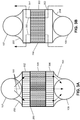
Figure 3A illustrates a schematic view of a cold flow in the heat exchanger, according to an embodiment. -
Figure 3B illustrates a schematic view of a hot flow in the heat exchanger, according to an embodiment. -
Figure 4A illustrates an exploded view of a cell of a plate assembly of the heat exchanger, according to an embodiment. -
Figure 4B illustrates a perspective view of the cell of the plate assembly, according to an embodiment. -
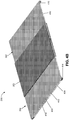
Figure 5 illustrates a perspective view of the plate assembly, according to an embodiment. -
Figure 6 illustrates a partial sectional view of the plate assembly and a plenum, according to an embodiment. -
Figure 7A illustrates a partial perspective view of the plate assembly and the plenum, according to an embodiment. -
Figure 7B illustrates a sectional view of the plate assembly and the plenum, according to an embodiment. -
Figure 8 illustrates a perspective view of the plate assembly and two plenums, according to an embodiment. -
Figure 9 illustrates a conceptual diagram of thermal expansion in the plate assembly, according to an embodiment. -
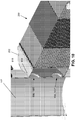
Figure 10 illustrates a sectional view of the plate assembly, the plenum, and a manifold, according to an embodiment. -
Figure 11 illustrates an enlarged view of part of the plate assembly, the plenum, and the manifold, showing a connection therebetween, according to an embodiment. -
Figure 12A illustrates a sectional view of the heat exchanger, showing the hot-side flow proceeding therethrough, according to an embodiment. -
Figure 12B illustrates a sectional view of the heat exchanger, showing the cold-side flow proceeding therethrough. -
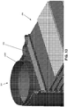
Figure 13 illustrates a perspective view of a portion of another embodiment of the heat exchanger. -
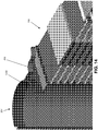
Figure 14 illustrates a sectional view of the portion of the heat exchanger ofFigure 13 , according to an embodiment. - The following disclosure describes several embodiments for implementing different features, structures, or functions of the invention. Embodiments of components, arrangements, and configurations are described below to simplify the present disclosure; however, these embodiments are provided merely as examples and are not intended to limit the scope of the invention. Additionally, the present disclosure may repeat reference characters (e.g., numerals) and/or letters in the various embodiments and across the Figures provided herein. This repetition is for the purpose of simplicity and clarity and does not in itself dictate a relationship between the various embodiments and/or configurations discussed in the Figures. Moreover, the formation of a first feature over or on a second feature in the description that follows may include embodiments in which the first and second features are formed in direct contact, and may also include embodiments in which additional features may be formed interposing the first and second features, such that the first and second features may not be in direct contact. Finally, the embodiments presented below may be combined in any combination of ways, e.g., any element from one exemplary embodiment may be used in any other exemplary embodiment, without departing from the scope of the disclosure.
- Additionally, certain terms are used throughout the following description and claims to refer to particular components. As one skilled in the art will appreciate, various entities may refer to the same component by different names, and as such, the naming convention for the elements described herein is not intended to limit the scope of the invention, unless otherwise specifically defined herein. Further, the naming convention used herein is not intended to distinguish between components that differ in name but not function. Additionally, in the following discussion and in the claims, the terms "including" and "comprising" are used in an open-ended fashion, and thus should be interpreted to mean "including, but not limited to." All numerical values in this disclosure may be exact or approximate values unless otherwise specifically stated. Accordingly, various embodiments of the disclosure may deviate from the numbers, values, and ranges disclosed herein without departing from the intended scope. In addition, unless otherwise provided herein, "or" statements are intended to be non-exclusive; for example, the statement "A or B" should be considered to mean "A, B, or both A and B."
- As used herein, the terms "inner" and "outer"; "up" and "down"; "first" and "second"; "upward" and "downward"; "above" and "below"; "inward" and "outward"; "vertical" and "horizontal"; and other like terms as used herein refer to relative positions and/or directions to one another and are not intended to denote a particular direction or spatial orientation. The terms "couple," "coupled," "connect," "connection," "connected," "in connection with," and "connecting" refer to "in direct connection with" or "in connection with via one or more intermediate elements or members."
-
Figure 1 illustrates a perspective view of aheat exchanger 100, according to an embodiment. Theheat exchanger 100 generally includes a hot-side fluid inlet 102, a hot-side fluid outlet 104, a cold-side fluid inlet 106, and a cold-side fluid outlet 108. It will be appreciated that the inlets and outlets may be swapped, and the cold-side and the hot-side may also be swapped, with the illustrated embodiment being merely an example. Thus, the hot and cold side inlets and outlets may also be more generically referred to as "first" and "second" inlets and outlets, respectively. Further, theinlets outlets - The
heat exchanger 100 may also include acasing 110, through which theinlets outlets casing 110 may include endwalls side inlet 102 and the hot-side outlet 104 may extend, respectively. Thecasing 110 may also include atop wall 116 through which the cold-side inlet 106 andoutlet 108 may extend. Thecasing 110 may also include a bottom wall (not visible), and one or more of the cold-side inlet 106 andoutlet 108 may also extend therethrough; however, in other embodiments, the cold-side inlet 106 andoutlet 108 may terminate within thecasing 110.Side walls casing 110 may extend between thetop wall 116 and bottom wall, and between theend walls - The
casing 110 may include aflange 124, which may run along the perimeter of a medial cross-section of thecasing 110. Theflange 124 may also, in some embodiments, run along the edge of theside walls end walls flange 124 may include two relatively thin sheets of, e.g., metal, which are connected together at their tops, e.g., using fasteners such as a bolts, rivets, screws, clamps, etc. Accordingly, theflange 124 may be configured to flex about its top, allowing the base of theflange 124 to expand and contract, thereby compensating for thermal expansion of thecasing 110. - With continuing reference to
Figure 1 ,Figure 2 illustrates a sectional view of theheat exchanger 100, showing the interior of thecasing 110, according to an embodiment. As shown, the hot-side inlet 102 andoutlet 104 may be open into the interior of thecasing 110, while the cold-side inlet 106 andoutlet 108 may be coupled tomanifolds side inlet 106 andoutlet 108 may be configured for use with a higher-pressure fluid than the hot-side inlet 102 andoutlet 104, with themanifolds casing 110, allowing thecasing 110 walls to be constructed from relatively thin material. In some embodiments, themanifolds - Further, the
heat exchanger 100 may include aplate assembly 200 near the middle, which will be described in greater detail below.Plenums plate assembly 200 and to themanifolds plenums plate assembly 200 and the cold-side inlet 106 and outlet 108 (via themanifolds 107, 109), respectively, as will be described in greater detail below. Theplenums manifolds plate assembly 200, as will be described in greater detail below. Accordingly, in some embodiments, as shown, theplenum plenums - The
heat exchanger 100 may also include one or more divider walls (two are shown: 206, 208). Thedivider walls plate assembly 200 and may direct fluid from the hot-side inlet 102, to theplate assembly 200, and from theplate assembly 200 to the hot-side outlet 104. In an embodiment, thedivider walls divider walls -
Figure 3A illustrates a simplified, schematic flow diagram for acold flow 300 through theheat exchanger 100, according to an embodiment. As shown, thecold flow 300 may be received into theplenum 202 from the manifold 107 that is connected to the cold-side inlet 106 (Figure 1 ). Thecold flow 300 may then be directed through afirst header section 302 of theplate assembly 200, though a heat-transfer fin array 304, through asecond header section 306, and into theplenum 204. Thecold flow 300 may then be delivered into the cold-side outlet 108. -
Figure 3B illustrates a simplified, schematic flow diagram for ahot flow 350 through theheat exchanger 100, according to an embodiment. Thehot flow 350 may be received into thecasing 110 through the hot-side inlet 102 (Figure 2 ). Thehot flow 350 may then be turned inward (e.g., by thedivider walls Figure 2 ), toward theplate assembly 200. Thehot flow 350 may then be received into afirst header section 352, with thehot flow 350 proceeding generally in a transverse (i.e., in through the sides, rather than the ends) direction to theplate assembly 200. Thehot flow 350 may then turn and flow through a heat-transfer fin array 353. Heat may transfer across the plates of theplate assembly 200, specifically in the heat-transfer fin arrays hot flow 350 into thecold flow 300. Thehot flow 350 may then flow into asecond header section 354, may be turned to a transverse direction to theplate assembly 200, and then proceed out into thecasing 110 and ultimately to the hot-side outlet 104 (Figure 2 ). - Accordingly, both the cold and
hot flows plate assembly 200, but may be maintained as separate flows by proceeding through partitioned channels between plates of theplate assembly 200, as will be explained in greater detail below. Further, theseparate flows transfer fin arrays header sections -
Figure 4A illustrates an exploded view of acell 400 of the plate assembly 200 (e.g.,Figure 2 ), according to an embodiment.Figure 4B illustrates a perspective view of theplate assembly 200, according to an embodiment. Referring to bothFigures 4A and4B , thecell 400 may include twoplates transfer fins 353 may be attached (e.g., welded or brazed) to thetop plate 402, and may also be attached to alower plate 404 of an adjacent cell (not shown). On either end of the heat-transfer fin array 353, theheader sections - The heat-
transfer fin array 304 may be positioned between theplates transfer fins 304, theheader sections Header fins header sections header fins header fins header fins plate assembly 200 by connecting between theplates - In an embodiment, a cold-side flowpath may extend through the channel defined between the
plates header fins more cells 400 are stacked together, a hot-side flowpath may be formed between one of theplates header sections plates - The
cell 400 also includes hot-side baffles 410 and cold-side baffles 412 that may extend along adjacent edges of theplates plates transfer fin array 353, as well as preventing ingress of cold fluid from proceeding into the hot-side flowpath. Similarly, the cold-side baffles 412 may be formed with a "channel" construction, and extend in a second direction, e.g. along another edge of theplates baffles plates baffles respective plates baffles baffles transfer fin arrays baffles cell 400. - Further, the
plate assembly 200 may includeblocks blocks 414 may be sized to fit into the channels formed by the hot-side baffles 410, and theblocks 416 may be sized to fit into the channels formed by the cold-side baffles 412. Theblocks respective baffles blocks 416 may be positioned in the middle (or elsewhere), lengthwise, of thebaffle 412, providing increased rigidity thereto. In some embodiments, one ormore blocks 414 may be secured in thebaffle 410 between the ends thereof, as well. Theblocks plate assembly 200, as well as providing a connection point for theplate assembly 200, as will be described in greater detail below. - Any number of
plates cells 400 may be employed in theplate assembly 200. However, for the sake of manufacturing ease and scalability, theplate assembly 200 may be formed from one or more modular sets of a certain number ofstacked cells 400, e.g., five, 10, 20, 30, 100, etc.Figure 5 illustrates a perspective view of theplate assembly 200, including twosets set - At the interface between the
sets sets Figure 4A ), such that, when connected together, as shown, the combination results in another hot-side flowpath between two plates of substantially the same size as the other hot flowpaths. Aconnector baffle 504C may be provided at the top of theset 500 of cells, and anotherconnector baffle 504D may be provided at the bottom of theset 502 of cells. Moreover, blocks 506 may be positioned in the ends of theconnector plates 504A-D, similar to theblocks Figures 4A and4B . Accordingly, connector baffles 504A-D may be attached to the top and/or bottom plate of each set 500, 502 of cells, allowing for a repeatable and modular design for theplate assembly 200. - Some of the connector baffles, e.g., connector baffles 504A, 504B, may thus serve to couple adjacent,
stacked sets plate assembly 200, may serve to connect theplate assembly 200 with theplenums 202, 204 (Figure 2 ). For example,Figure 6 illustrates a sectional view of theplate assembly 200 attached to one of theplenums 202, according to an embodiment. As shown, anend 600 of atop plate 602 of theplenum 202 may be slid into the channel formed by theconnector baffle 504C. Thetop plate 602 may then be secured to theconnector baffle 504C using a suitable connection process and/or device. Theplenum 202 may also include a bottom plate, which is not visible, which may be likewise coupled to theconnector baffle 504D (Figure 5 ). Theplenum 204 may be similarly attached to theplate assembly 200. -
Figure 6 also illustrates the continuation of theplate assembly 200 described above with reference toFigures 4A and4B . As shown inFigure 6 , anothercell 604 may begin below thecell 400, and may be connected thereto by the hot-side baffle 410, providing the hot-side flowpath between theplate 404 and aplate 606 of theother cell 604. - In addition, the
plenum 202 may be welded to and/or along theblocks plate assembly 200. This connection may not only form a fluid-tight seal between theplenum 202 and theplate assembly 200, but may also distribute any loads on theplenum 202 across the entire stack of plates, and along a line of maximum rigidity provided by the stackedblocks cold flow 300 directed into theplenum 202 from the manifold 107 (received fluid from the cold-side inlet 106) proceeds into the cold flowpath, e.g., between theheader fins 406 between theplates plenum 202 and into the hot flowpath of theplate assembly 200, and vice versa, may be blocked by the hot-side baffles 410. -
Figures 7A and7B illustrate another embodiment of theplenum 202 attached to theplate assembly 200. In this embodiment, theplenum 202 is provided with atransition plate 700, which may be of a thickness between that of thetop plate 602 of theplenum 202 and theconnector baffle 504C. Thetransition plate 700 may thus mitigate the effects of the thermal gradient between the cold and hot fluids, which may cause unequal thermal expansion. Accordingly, in this embodiment, thetransition plate 700 is received into theconnector baffle 504C, e.g., around theblock 506, and is also attached to thetop plate 602, e.g., welded thereto. - As also noted above,
Figure 7A shows aweldment 702 between theplenum 202 and the corner of theplate assembly 200. In particular, an edge weld proceeds long theblocks baffles plate assembly 200, rather than on a single plate. -
Figure 8 illustrates a perspective view of theplate assembly 200 and theplenum plenums trough 814 between tworounded crests trough 814 may be configured to receive one of themanifolds side inlet 106 oroutlet 108. One or more openings (two are shown: 806, 808) may be formed in thetrough 814, and may be aligned with corresponding openings in the cold-side inlet 106 oroutlet 108, so as to communicate fluid therebetween. - The shape of the
plenum heat exchanger 100.Figure 9 illustrations a conceptual diagram showing such thermal expansion compensation, to an exaggerated degree for purposes of discussion herein, according to an embodiment. As can be seen, theplate assembly 200 may expand as proceeding to its vertical middle, e.g., bowing toward theoutlet manifold 109 and away from theinlet manifold 107. Themanifolds - The
plenum heat exchanger 100. In particular, theplenum top plate 602 being visible) connected to theconnector baffle 504A (see, e.g.,Figure 5 ), may be relatively rigid in a direction parallel to the plates of theplate assembly 200 at the vertical extremes of theplenum plenum plenum - For example, referring again to
Figure 8 , thecrests trough 814 deepens toward the vertical middle of theplenum 202, while thecrests plenum 204 may become wider, as thetrough 814 flattens. Thus, because of the curvature of thecrests plenum -
Figure 10 illustrates a sectional view of theplate assembly 200, theplenum 202, and the manifold 107, according to an embodiment. Theplenum 202 receives the manifold 107 in thetrough 814 thereof, allowing the above-described flexing. Further, theholes manifold 107. The manifold 109 may have similar holes, which may align with corresponding holes formed in theplenum 204. -
Figure 11 illustrates an enlarged, sectional view of the connection between the manifold 107, thecasing 110, and theplenum 202, according to an embodiment. For example, the connection may be formed by aflange 1100, which may be welded to themanifold 107. Afastener 1102, such as a screw, may be received through theflange 1100. Thefastener 1102 may secure aring 1104, which may be made from metal, to theflange 1100, on the outside of thecasing 110. Further, thering 1104 may include arecess 1106 for a seal 1108, such as a rope seal. The seal 1108 may form an air-tight seal between thecasing 110 and thering 1104. - A
gap 1110 may be defined between theflange 1100 and at least a portion of thecasing 110. For example, as shown, thecasing 110 may be double-walled, thus including anouter wall 1112 and aninner wall 1114. Theflange 1100 may be connected to theouter wall 1112, but spaced apart frominner wall 1114 by thegap 1110. Thegap 1110 may thus define an area allowing for thermal expansion of thecasing 110, e.g., theinner wall 1114 thereof. - Operation of the
heat exchanger 100 may be appreciated with reference toFigures 12A and 12B , which show thecold flow 300 andhot flow 350, respectively, in the structure of theheat exchanger 100 described above. As an example, thecold flow 300 may fed through theinlet 106 and into themanifold 107. Thecold flow 300 may then proceed through holes 1002, 1004 in the manifold 107, intoholes plenum 202. Theplenum 202 may direct the cold flow toward theplate assembly 200. As best seen inFigure 6 , baffles 410 may be positioned between everysecond plate baffles 410 may provide a channel for continued cold flow from theplenum 202 into theplate assembly 200, e.g., betweenheader fins 406. In addition, theplenum 202 may be secured to theplate assembly 200, e.g., with theend 600 of the top plate 602 (or a transition plate 700) received into theconnector baffle 504C, and a similar connection made at the bottom of theplenum 202. As also described above, the vertical edges of theplenum 202 may be welded to theplate assembly 200, e.g., using theblocks - The
cold flow 300 may then flow through theplate assembly 200, with the baffles 412 (Figure 4 ) preventing the cold flow from escaping transversely. Thecold flow 300 may then exit theplate assembly 200, flowing into theplenum 204, the manifold 109, and then theoutlet 108. - Referring specifically to
Figure 12B , and with additional reference toFigure 2 , thehot flow 350 may enter thecasing 110 via theinlet 102 and flow around themanifold 109. The connection between the manifold 109 and theplenum 204 may prevent mixing of the hot flow with the cold flow. Thehot flow 350 may meet thedivider walls plate assembly 200. Thebaffles 412 may prevent the hot flow from entering the channels provided for the cold flow, while thebaffles 410 may prevent the hot flow from escaping from the channels provided for the hot flow. - The hot flow may flow through the
first header section 352, turning toward the heat-transfer fin array 353. The hot flow may then flow though the heat-transfer fin array 353, thereby transferring heat to the cold flow in the heat-transfer fin array 304 (e.g.,Figure 4A ). Thehot flow 350 may then proceed out of theplate assembly 200 via thesecond header section 354. Thebaffles 410 may prevent the hot flow from entering theplenum 202, and instead the hot flow may proceed outwards, into thecasing 110. The hot flow may further be directed by thedivider wall 208 to flow around themanifold 107 and to the hot-side outlet 104. - Because a large thermal gradient may exist between the hot and cold flows, which may flow in close proximity to one another, e.g., in the
plate assembly 200, theheat exchanger 100 is provided with several thermal-expansion compensation features, as described above. Among those, as shown inFigure 1 , theflange 124 is bellows shaped, allowing for expansion and contraction of thecasing 110. As shown, for example inFigure 2 , the shape of theplenum plate assembly 200. As shown inFigure 7 , theplenum transition plate 700, which provides an intermediate thickness between theconnector baffle 504C and the top plate 602 (similar connection made at the bottom of theplenum 202, 204). As shown inFigure 11 , the connection between thecasing 110 and themanifolds thermal expansion gap 1110. - Further, the design of the
plate assembly 200 may be modular, facilitating scalability by allowing for designs with additional or fewer plates. For example, theplate assembly 200 may be rectangular, which may maximize material usage and minimize scrap, although other shapes may also be employed. Moreover, the construction of theplates plates plate assembly 200. In addition, the baffles and blocks may provide rigidity and strength in theplate assembly 200 at the corners thereof, to which theplenum entire plate assembly 200. -
Figures 13 and14 illustrate another embodiment of theheat exchanger 100. In particular,Figure 13 illustrates a perspective view of a portion of the interior of theheat exchanger 100, andFigure 14 illustrates a sectional view of a similar portion, according to an embodiment. In this embodiment, the manifold 107 (e.g.,Figure 2 ) is partially removed, and its remainder takes the form of aflange 1200. Theflange 1200 connects the interior of theplenum 202 with the cold-side inlet 106 (e.g.,Figure 2 ), thereby directing fluid from the cold-side inlet 106 (e.g.,Figure 2 ) to within theplenum 202. The fluid in theplenum 202 is then directed to the appropriate channels of theplate assembly 200 by the plenum walls and the baffles, as described above. It will be appreciated that the manifold 109 (e.g.,Figure 2 ) may be modified to incorporate a similar flange as theflange 1200 for receiving fluid from theplenum 204 into the cold-side outlet 108 (e.g.,Figure 2 ). - The foregoing has outlined features of several embodiments so that those skilled in the art may better understand the present disclosure. Those skilled in the art should appreciate that they may readily use the present disclosure as a basis for designing or modifying other processes and structures for carrying out the same purposes and/or achieving the same advantages of the embodiments introduced herein. Those skilled in the art should also realize that such equivalent constructions do not depart from the scope of the present disclosure, and that they may make various changes, substitutions, and alterations herein without departing from the scope of the present disclosure. The invention is defined by the appended claims.
Claims (13)
- A heat exchanger, comprising:a casing (110) having a first inlet (102), a first outlet (104), a second inlet (106), and a second outlet (108);
a plate assembly(200) positioned between the first inlet and the first outlet and between the second inlet and the second outlet and at least partially in the casing, wherein the plate assembly is configured to transfer heat between a first fluid and a second fluid;a first plenum (202) connecting a first side of the plate assembly and configured to direct the first fluid from the first inlet to the plate assembly; anda second plenum (204) connecting a second side of the plate assembly and configured to direct the first fluid from the plate assembly to the first outlet, wherein an exterior of the second plenum is in contact with the second fluid, and wherein the second plenum is configured to resiliently deflect in response to thermal expansion of the second plenum, the plate assembly, the casing, or a combination thereof;
characterized in that:
the plate assembly (200) comprises a plurality of cells (400), each cell comprising:a first plate (402);a second plate (404);a header fin (406) positioned between the first and second plates;a first baffle (410) extending in a first direction and positioned between the first plate and the second plate; anda second baffle (412) extending in a second direction, transverse to the first direction, and connected to the first plate, on an opposite face of the first plate from the first baffle. - The heat exchanger of claim 1, wherein the first plenum (202) comprises a trough (814) and two crests (810, 812), such that bending deflection of the first plenum is provided by a curvature of the crests, to compensate for thermal expansion.
- The heat exchanger of claim 1, wherein:
the second inlet (106) communicates with the plate assembly (200) through the casing (110) and is prevented from communicating with an interior of the first plenum (202) and an interior of the second plenum (204); and
the second outlet (108) communicates with the plate assembly through the casing (110) and is prevented from communicating with the interior of the first plenum (202) and the interior of the second plenum (204). - The heat exchanger of claim 3, further comprising one or more divider walls (206, 208) positioned adjacent to the plate assembly (200), the one or more divider walls being configured to channel a fluid received through the second inlet (106) and direct the fluid to the plate assembly.
- The heat exchanger of claim 1, wherein the casing (110) comprises a flange (124), the flange being configured to expand and contract to compensate for thermal expansion between the plate assembly (200) and the casing.
- The heat exchanger of claim 1, further comprising:a first manifold (107) connected to and extending from the first inlet (102) and coupled to the first plenum (202) so as to communicate fluid from the first inlet to within the first plenum; anda second manifold (109) connected to and extending from the first outlet (104) so as to communicate fluid from the second plenum (204) to the first outlet (104).
- The heat exchanger of claim 6, wherein the casing (110) forms a connection with the first manifold (107) and a connection with the second manifold (109), and wherein the connections each define a sealed gap (1110) allowing for thermal expansion of the casing.
- The heat exchanger of claim 1, wherein the plurality of cells (400) comprises a first cell and a second cell, the second plate (404) of the first cell being connected to the first plate (402) of the second cell, wherein a first header section (352) is defined between the second plate of the first cell and the first plate of the second cell, a second header section (354) is defined between the second plate of the first cell and the first plate of the second cell, and wherein a heat-transfer fin array (304, 353) is connected to the second plate of the first cell and the first plate of the second cell between the first and second header sections.
- The heat exchanger of claim 1, wherein each of the plurality of cells (400) further comprises a first header section (352) including the header fin (406) defined between the first and second plates (402, 404), a second header section (354) including another header fin (408) between the first and second plates, and a heat-transfer fin array (304) positioned between the first and second plates and between the first and second header sections.
- The heat exchanger of claim 1, further comprising:a first block (414) positioned in the first baffle (410), proximate an end thereof; anda second block (416) positioned in the second baffle (412), proximate an end thereof, such that the first block is positioned at least partially above the second block, wherein the first plenum (202) is attached to the plate assembly (200) along the first and second blocks.
- The heat exchanger of claim 1, further comprising a connector baffle (504C) attached to the second plate (404), on an opposite face of the second plate from the first baffle (410), wherein the plenum comprises a top plate (602) that is received into the connector baffle and connected thereto.
- The heat exchanger of claim 1, further comprising a first set of cells (500) including the first and second plates (402, 404), and a second set of cells (502) coupled to the first set of cells, the first set cells comprising a first connector baffle (504A) that is about half of a height of the first baffle (410), and the second set of cells comprising a second connector baffle (504B) that is about half of a height of the first baffle, the first and second sets of cells being connected together by adjoining the first and second connector baffles.
- The heat exchanger of claim 1, wherein a hot flow of fluid flows through at least a portion of the plate assembly (200) in a first direction, and a cold flow of fluid flows through at least the portion of the plate assembly in a second direction, the first and second directions being opposites.
Applications Claiming Priority (3)
| Application Number | Priority Date | Filing Date | Title |
|---|---|---|---|
| US201662345501P | 2016-06-03 | 2016-06-03 | |
| US201662345996P | 2016-06-06 | 2016-06-06 | |
| PCT/US2017/035750 WO2017210602A1 (en) | 2016-06-03 | 2017-06-02 | Counter-flow heat exchanger |
Publications (3)
| Publication Number | Publication Date |
|---|---|
| EP3465049A1 EP3465049A1 (en) | 2019-04-10 |
| EP3465049A4 EP3465049A4 (en) | 2020-01-22 |
| EP3465049B1 true EP3465049B1 (en) | 2021-04-07 |
Family
ID=60477880
Family Applications (1)
| Application Number | Title | Priority Date | Filing Date |
|---|---|---|---|
| EP17807598.2A Active EP3465049B1 (en) | 2016-06-03 | 2017-06-02 | Counter-flow heat exchanger |
Country Status (3)
| Country | Link |
|---|---|
| US (1) | US10222129B2 (en) |
| EP (1) | EP3465049B1 (en) |
| WO (1) | WO2017210602A1 (en) |
Families Citing this family (5)
| Publication number | Priority date | Publication date | Assignee | Title |
|---|---|---|---|---|
| US11035626B2 (en) * | 2018-09-10 | 2021-06-15 | Hamilton Sunstrand Corporation | Heat exchanger with enhanced end sheet heat transfer |
| DK180516B1 (en) * | 2019-11-14 | 2021-06-03 | Danfoss As | Multi-pass heat exchanger |
| EP4220060B1 (en) * | 2022-01-27 | 2026-01-07 | Bosal Flanders NV | Heat exchanger unit and method for fluid to passively bypassing a heat exchanger |
| CN114543562A (en) * | 2022-02-25 | 2022-05-27 | 北京市京海换热设备制造有限责任公司 | Core-pulling type welded plate shell type heat exchanger |
| CN114688900B (en) * | 2022-03-04 | 2024-02-20 | 杭氧集团股份有限公司 | Multi-module combined plate-fin heat exchanger |
Citations (6)
| Publication number | Priority date | Publication date | Assignee | Title |
|---|---|---|---|---|
| US2875986A (en) | 1957-04-12 | 1959-03-03 | Ferrotherm Company | Heat exchanger |
| US3759323A (en) | 1971-11-18 | 1973-09-18 | Caterpillar Tractor Co | C-flow stacked plate heat exchanger |
| US4297775A (en) | 1980-05-08 | 1981-11-03 | The Trane Company | Method for joining two plate type heat exchanger core sections with an intermodular layer for improved heat transfer |
| FR2793548A1 (en) | 2000-07-21 | 2000-11-17 | Air Liquide | Plate vaporizer-condenser operating as a thermosiphon in which the exchange corrugations of the second passage are vertical and the exchange body has two inlet boxes spaced over its length |
| US6283199B1 (en) | 1999-05-20 | 2001-09-04 | Toyo Radiator Co., Ltd. | Heat exchanger |
| EP3150952A1 (en) | 2015-10-02 | 2017-04-05 | Alfa Laval Corporate AB | Heat transfer plate and plate heat exchanger |
Family Cites Families (16)
| Publication number | Priority date | Publication date | Assignee | Title |
|---|---|---|---|---|
| US4310960A (en) * | 1973-04-16 | 1982-01-19 | The Garrett Corporation | Method of fabrication of a formed plate, counterflow fluid heat exchanger and apparatus thereof |
| US3866674A (en) * | 1973-10-01 | 1975-02-18 | Gen Electric | Gas turbine regenerator |
| US4005573A (en) * | 1975-10-01 | 1977-02-01 | General Motors Corporation | Recuperative mounting |
| US4442886A (en) * | 1982-04-19 | 1984-04-17 | North Atlantic Technologies, Inc. | Floating plate heat exchanger |
| US6174454B1 (en) * | 1999-01-29 | 2001-01-16 | National Science Council | Slurry formulation for selective CMP of organic spin-on-glass insulating layer with low dielectric constant |
| SE9601438D0 (en) | 1996-04-16 | 1996-04-16 | Tetra Laval Holdings & Finance | plate heat exchangers |
| US20020153129A1 (en) * | 2000-04-25 | 2002-10-24 | White Stephen L. | Integral fin passage heat exchanger |
| US6516874B2 (en) * | 2001-06-29 | 2003-02-11 | Delaware Capital Formation, Inc. | All welded plate heat exchanger |
| US6574950B2 (en) * | 2001-10-01 | 2003-06-10 | Ingersoll-Rand Energy Systems Corporation | Thermally responsive recuperator housing |
| DE10204107B4 (en) * | 2002-02-01 | 2018-12-13 | Mahle International Gmbh | Exhaust gas heat exchanger |
| US8272431B2 (en) | 2005-12-27 | 2012-09-25 | Caterpillar Inc. | Heat exchanger using graphite foam |
| US8915292B2 (en) * | 2006-02-07 | 2014-12-23 | Modine Manufacturing Company | Exhaust gas heat exchanger and method of operating the same |
| DE102006042936A1 (en) * | 2006-09-13 | 2008-03-27 | Modine Manufacturing Co., Racine | Heat exchanger, in particular exhaust gas heat exchanger |
| EP2015017A1 (en) * | 2007-07-12 | 2009-01-14 | Hexion Specialty Chemicals Research Belgium S.A. | Heat exchanger |
| US20130299134A1 (en) * | 2012-04-23 | 2013-11-14 | Nicholas H. Deschamps | Thermal expansion joint and heat exchanger |
| US20150144309A1 (en) * | 2013-03-13 | 2015-05-28 | Brayton Energy, Llc | Flattened Envelope Heat Exchanger |
-
2017
- 2017-06-02 EP EP17807598.2A patent/EP3465049B1/en active Active
- 2017-06-02 WO PCT/US2017/035750 patent/WO2017210602A1/en not_active Ceased
- 2017-06-02 US US15/612,620 patent/US10222129B2/en active Active
Patent Citations (6)
| Publication number | Priority date | Publication date | Assignee | Title |
|---|---|---|---|---|
| US2875986A (en) | 1957-04-12 | 1959-03-03 | Ferrotherm Company | Heat exchanger |
| US3759323A (en) | 1971-11-18 | 1973-09-18 | Caterpillar Tractor Co | C-flow stacked plate heat exchanger |
| US4297775A (en) | 1980-05-08 | 1981-11-03 | The Trane Company | Method for joining two plate type heat exchanger core sections with an intermodular layer for improved heat transfer |
| US6283199B1 (en) | 1999-05-20 | 2001-09-04 | Toyo Radiator Co., Ltd. | Heat exchanger |
| FR2793548A1 (en) | 2000-07-21 | 2000-11-17 | Air Liquide | Plate vaporizer-condenser operating as a thermosiphon in which the exchange corrugations of the second passage are vertical and the exchange body has two inlet boxes spaced over its length |
| EP3150952A1 (en) | 2015-10-02 | 2017-04-05 | Alfa Laval Corporate AB | Heat transfer plate and plate heat exchanger |
Non-Patent Citations (3)
| Title |
|---|
| "Distillation: Operation and Applications", 1 January 2014, ELSEVIER, article MOLL ANTON: "Air Distillation (chapter 6)", pages: 255 - 295, XP093093334 |
| "The Standards of the Brazed Aluminium Plate-Fin Heat Exchanger Manufacturers' Association - Second Edition", 2000, THE STANDARDS OF THE BRAZED ALUMINIUM PLATE-FIN HEAT EXCHANGER MANUFACTURERS' ASSOCIATION, pages: 1 - 70 |
| .: "Plate-fin Heat Exchangrers Guide to their Specification and Use", 1987, M.A. TAYLOR, pages: 1.1 - 5.23 |
Also Published As
| Publication number | Publication date |
|---|---|
| EP3465049A1 (en) | 2019-04-10 |
| US20170350656A1 (en) | 2017-12-07 |
| EP3465049A4 (en) | 2020-01-22 |
| WO2017210602A1 (en) | 2017-12-07 |
| US10222129B2 (en) | 2019-03-05 |
Similar Documents
| Publication | Publication Date | Title |
|---|---|---|
| US10222129B2 (en) | Counter-flow heat exchanger | |
| CA2839884C (en) | Plate heat exchanger including separating elements | |
| US7007749B2 (en) | Housing-less plate heat exchanger | |
| US4270602A (en) | Heat exchanger | |
| EP2176616B1 (en) | Heat exchanger | |
| CN111981876A (en) | Plate type heat exchanger | |
| CN100587381C (en) | Improved heat exchanger housing and seals | |
| CN210741194U (en) | a plate heat exchanger | |
| GB2275996A (en) | Plate stack heat exchanger | |
| US6012514A (en) | Tube-in tube heat exchanger | |
| CA1299167C (en) | Heat exchanger | |
| US6543530B2 (en) | Heat exchanger having an improved pipe connecting structure | |
| CN109791030B (en) | Heat exchanger with high durability | |
| EP3775746B1 (en) | Tube-fin heat exchanger | |
| JP2005274045A (en) | Heat source device | |
| CN115435617A (en) | Integrated refrigerant heat exchange module and manufacturing method thereof | |
| US20070235174A1 (en) | Heat exchanger | |
| EP1938037A1 (en) | Plate heat exchanger and method for constructing pressure-proof plate heat exchanger | |
| US20210180883A1 (en) | Heat exchanger with one-piece through fittings | |
| WO2022059437A1 (en) | Heat exchanger | |
| JP3054888U (en) | Plate fin type heat exchanger | |
| CN222378889U (en) | Heat exchange plate, heat exchanger core and all-welded plate-shell heat exchanger | |
| EP3470762A1 (en) | Plate-type heat exchanger | |
| JPS5928218Y2 (en) | Heat exchanger for high pressure fluid | |
| JPH0674601A (en) | Stacked heat exchanger |
Legal Events
| Date | Code | Title | Description |
|---|---|---|---|
| STAA | Information on the status of an ep patent application or granted ep patent |
Free format text: STATUS: THE INTERNATIONAL PUBLICATION HAS BEEN MADE |
|
| PUAI | Public reference made under article 153(3) epc to a published international application that has entered the european phase |
Free format text: ORIGINAL CODE: 0009012 |
|
| STAA | Information on the status of an ep patent application or granted ep patent |
Free format text: STATUS: REQUEST FOR EXAMINATION WAS MADE |
|
| 17P | Request for examination filed |
Effective date: 20181220 |
|
| AK | Designated contracting states |
Kind code of ref document: A1 Designated state(s): AL AT BE BG CH CY CZ DE DK EE ES FI FR GB GR HR HU IE IS IT LI LT LU LV MC MK MT NL NO PL PT RO RS SE SI SK SM TR |
|
| AX | Request for extension of the european patent |
Extension state: BA ME |
|
| DAV | Request for validation of the european patent (deleted) | ||
| DAX | Request for extension of the european patent (deleted) | ||
| A4 | Supplementary search report drawn up and despatched |
Effective date: 20200107 |
|
| RIC1 | Information provided on ipc code assigned before grant |
Ipc: F28F 9/22 20060101ALI20191219BHEP Ipc: F28F 9/02 20060101ALI20191219BHEP Ipc: F28D 9/00 20060101AFI20191219BHEP |
|
| GRAP | Despatch of communication of intention to grant a patent |
Free format text: ORIGINAL CODE: EPIDOSNIGR1 |
|
| STAA | Information on the status of an ep patent application or granted ep patent |
Free format text: STATUS: GRANT OF PATENT IS INTENDED |
|
| GRAJ | Information related to disapproval of communication of intention to grant by the applicant or resumption of examination proceedings by the epo deleted |
Free format text: ORIGINAL CODE: EPIDOSDIGR1 |
|
| STAA | Information on the status of an ep patent application or granted ep patent |
Free format text: STATUS: REQUEST FOR EXAMINATION WAS MADE |
|
| INTG | Intention to grant announced |
Effective date: 20200909 |
|
| INTC | Intention to grant announced (deleted) | ||
| GRAP | Despatch of communication of intention to grant a patent |
Free format text: ORIGINAL CODE: EPIDOSNIGR1 |
|
| STAA | Information on the status of an ep patent application or granted ep patent |
Free format text: STATUS: GRANT OF PATENT IS INTENDED |
|
| INTG | Intention to grant announced |
Effective date: 20201030 |
|
| GRAS | Grant fee paid |
Free format text: ORIGINAL CODE: EPIDOSNIGR3 |
|
| RAP1 | Party data changed (applicant data changed or rights of an application transferred) |
Owner name: FLEXENERGY ENERGY SYSTEMS, INC. |
|
| GRAA | (expected) grant |
Free format text: ORIGINAL CODE: 0009210 |
|
| STAA | Information on the status of an ep patent application or granted ep patent |
Free format text: STATUS: THE PATENT HAS BEEN GRANTED |
|
| AK | Designated contracting states |
Kind code of ref document: B1 Designated state(s): AL AT BE BG CH CY CZ DE DK EE ES FI FR GB GR HR HU IE IS IT LI LT LU LV MC MK MT NL NO PL PT RO RS SE SI SK SM TR |
|
| REG | Reference to a national code |
Ref country code: GB Ref legal event code: FG4D |
|
| REG | Reference to a national code |
Ref country code: AT Ref legal event code: REF Ref document number: 1380229 Country of ref document: AT Kind code of ref document: T Effective date: 20210415 Ref country code: CH Ref legal event code: EP |
|
| REG | Reference to a national code |
Ref country code: DE Ref legal event code: R096 Ref document number: 602017036352 Country of ref document: DE |
|
| REG | Reference to a national code |
Ref country code: IE Ref legal event code: FG4D |
|
| REG | Reference to a national code |
Ref country code: LT Ref legal event code: MG9D |
|
| REG | Reference to a national code |
Ref country code: NL Ref legal event code: MP Effective date: 20210407 Ref country code: AT Ref legal event code: MK05 Ref document number: 1380229 Country of ref document: AT Kind code of ref document: T Effective date: 20210407 |
|
| PG25 | Lapsed in a contracting state [announced via postgrant information from national office to epo] |
Ref country code: FI Free format text: LAPSE BECAUSE OF FAILURE TO SUBMIT A TRANSLATION OF THE DESCRIPTION OR TO PAY THE FEE WITHIN THE PRESCRIBED TIME-LIMIT Effective date: 20210407 Ref country code: LT Free format text: LAPSE BECAUSE OF FAILURE TO SUBMIT A TRANSLATION OF THE DESCRIPTION OR TO PAY THE FEE WITHIN THE PRESCRIBED TIME-LIMIT Effective date: 20210407 Ref country code: NL Free format text: LAPSE BECAUSE OF FAILURE TO SUBMIT A TRANSLATION OF THE DESCRIPTION OR TO PAY THE FEE WITHIN THE PRESCRIBED TIME-LIMIT Effective date: 20210407 Ref country code: HR Free format text: LAPSE BECAUSE OF FAILURE TO SUBMIT A TRANSLATION OF THE DESCRIPTION OR TO PAY THE FEE WITHIN THE PRESCRIBED TIME-LIMIT Effective date: 20210407 Ref country code: BG Free format text: LAPSE BECAUSE OF FAILURE TO SUBMIT A TRANSLATION OF THE DESCRIPTION OR TO PAY THE FEE WITHIN THE PRESCRIBED TIME-LIMIT Effective date: 20210707 Ref country code: AT Free format text: LAPSE BECAUSE OF FAILURE TO SUBMIT A TRANSLATION OF THE DESCRIPTION OR TO PAY THE FEE WITHIN THE PRESCRIBED TIME-LIMIT Effective date: 20210407 |
|
| PG25 | Lapsed in a contracting state [announced via postgrant information from national office to epo] |
Ref country code: PL Free format text: LAPSE BECAUSE OF FAILURE TO SUBMIT A TRANSLATION OF THE DESCRIPTION OR TO PAY THE FEE WITHIN THE PRESCRIBED TIME-LIMIT Effective date: 20210407 Ref country code: LV Free format text: LAPSE BECAUSE OF FAILURE TO SUBMIT A TRANSLATION OF THE DESCRIPTION OR TO PAY THE FEE WITHIN THE PRESCRIBED TIME-LIMIT Effective date: 20210407 Ref country code: NO Free format text: LAPSE BECAUSE OF FAILURE TO SUBMIT A TRANSLATION OF THE DESCRIPTION OR TO PAY THE FEE WITHIN THE PRESCRIBED TIME-LIMIT Effective date: 20210707 Ref country code: PT Free format text: LAPSE BECAUSE OF FAILURE TO SUBMIT A TRANSLATION OF THE DESCRIPTION OR TO PAY THE FEE WITHIN THE PRESCRIBED TIME-LIMIT Effective date: 20210809 Ref country code: SE Free format text: LAPSE BECAUSE OF FAILURE TO SUBMIT A TRANSLATION OF THE DESCRIPTION OR TO PAY THE FEE WITHIN THE PRESCRIBED TIME-LIMIT Effective date: 20210407 Ref country code: RS Free format text: LAPSE BECAUSE OF FAILURE TO SUBMIT A TRANSLATION OF THE DESCRIPTION OR TO PAY THE FEE WITHIN THE PRESCRIBED TIME-LIMIT Effective date: 20210407 Ref country code: GR Free format text: LAPSE BECAUSE OF FAILURE TO SUBMIT A TRANSLATION OF THE DESCRIPTION OR TO PAY THE FEE WITHIN THE PRESCRIBED TIME-LIMIT Effective date: 20210708 Ref country code: IS Free format text: LAPSE BECAUSE OF FAILURE TO SUBMIT A TRANSLATION OF THE DESCRIPTION OR TO PAY THE FEE WITHIN THE PRESCRIBED TIME-LIMIT Effective date: 20210807 |
|
| REG | Reference to a national code |
Ref country code: DE Ref legal event code: R026 Ref document number: 602017036352 Country of ref document: DE |
|
| PLBI | Opposition filed |
Free format text: ORIGINAL CODE: 0009260 |
|
| PLAX | Notice of opposition and request to file observation + time limit sent |
Free format text: ORIGINAL CODE: EPIDOSNOBS2 |
|
| PG25 | Lapsed in a contracting state [announced via postgrant information from national office to epo] |
Ref country code: MC Free format text: LAPSE BECAUSE OF FAILURE TO SUBMIT A TRANSLATION OF THE DESCRIPTION OR TO PAY THE FEE WITHIN THE PRESCRIBED TIME-LIMIT Effective date: 20210407 Ref country code: DK Free format text: LAPSE BECAUSE OF FAILURE TO SUBMIT A TRANSLATION OF THE DESCRIPTION OR TO PAY THE FEE WITHIN THE PRESCRIBED TIME-LIMIT Effective date: 20210407 Ref country code: CZ Free format text: LAPSE BECAUSE OF FAILURE TO SUBMIT A TRANSLATION OF THE DESCRIPTION OR TO PAY THE FEE WITHIN THE PRESCRIBED TIME-LIMIT Effective date: 20210407 Ref country code: EE Free format text: LAPSE BECAUSE OF FAILURE TO SUBMIT A TRANSLATION OF THE DESCRIPTION OR TO PAY THE FEE WITHIN THE PRESCRIBED TIME-LIMIT Effective date: 20210407 Ref country code: RO Free format text: LAPSE BECAUSE OF FAILURE TO SUBMIT A TRANSLATION OF THE DESCRIPTION OR TO PAY THE FEE WITHIN THE PRESCRIBED TIME-LIMIT Effective date: 20210407 Ref country code: SK Free format text: LAPSE BECAUSE OF FAILURE TO SUBMIT A TRANSLATION OF THE DESCRIPTION OR TO PAY THE FEE WITHIN THE PRESCRIBED TIME-LIMIT Effective date: 20210407 Ref country code: SM Free format text: LAPSE BECAUSE OF FAILURE TO SUBMIT A TRANSLATION OF THE DESCRIPTION OR TO PAY THE FEE WITHIN THE PRESCRIBED TIME-LIMIT Effective date: 20210407 Ref country code: ES Free format text: LAPSE BECAUSE OF FAILURE TO SUBMIT A TRANSLATION OF THE DESCRIPTION OR TO PAY THE FEE WITHIN THE PRESCRIBED TIME-LIMIT Effective date: 20210407 |
|
| REG | Reference to a national code |
Ref country code: CH Ref legal event code: PL |
|
| 26 | Opposition filed |
Opponent name: L'AIR LIQUIDE, SOCIETE ANONYME POUR L'ETUDE ET L'EXPLOITATION DES PROCEDES GEORGES CLAUDE Effective date: 20220106 |
|
| REG | Reference to a national code |
Ref country code: BE Ref legal event code: MM Effective date: 20210630 |
|
| PG25 | Lapsed in a contracting state [announced via postgrant information from national office to epo] |
Ref country code: LU Free format text: LAPSE BECAUSE OF NON-PAYMENT OF DUE FEES Effective date: 20210602 |
|
| PG25 | Lapsed in a contracting state [announced via postgrant information from national office to epo] |
Ref country code: LI Free format text: LAPSE BECAUSE OF NON-PAYMENT OF DUE FEES Effective date: 20210630 Ref country code: IE Free format text: LAPSE BECAUSE OF NON-PAYMENT OF DUE FEES Effective date: 20210602 Ref country code: CH Free format text: LAPSE BECAUSE OF NON-PAYMENT OF DUE FEES Effective date: 20210630 |
|
| PLBB | Reply of patent proprietor to notice(s) of opposition received |
Free format text: ORIGINAL CODE: EPIDOSNOBS3 |
|
| PG25 | Lapsed in a contracting state [announced via postgrant information from national office to epo] |
Ref country code: IS Free format text: LAPSE BECAUSE OF FAILURE TO SUBMIT A TRANSLATION OF THE DESCRIPTION OR TO PAY THE FEE WITHIN THE PRESCRIBED TIME-LIMIT Effective date: 20210807 Ref country code: AL Free format text: LAPSE BECAUSE OF FAILURE TO SUBMIT A TRANSLATION OF THE DESCRIPTION OR TO PAY THE FEE WITHIN THE PRESCRIBED TIME-LIMIT Effective date: 20210407 |
|
| PG25 | Lapsed in a contracting state [announced via postgrant information from national office to epo] |
Ref country code: BE Free format text: LAPSE BECAUSE OF NON-PAYMENT OF DUE FEES Effective date: 20210630 |
|
| PLCK | Communication despatched that opposition was rejected |
Free format text: ORIGINAL CODE: EPIDOSNREJ1 |
|
| REG | Reference to a national code |
Ref country code: DE Ref legal event code: R100 Ref document number: 602017036352 Country of ref document: DE |
|
| PLBN | Opposition rejected |
Free format text: ORIGINAL CODE: 0009273 |
|
| STAA | Information on the status of an ep patent application or granted ep patent |
Free format text: STATUS: OPPOSITION REJECTED |
|
| 27O | Opposition rejected |
Effective date: 20230223 |
|
| PG25 | Lapsed in a contracting state [announced via postgrant information from national office to epo] |
Ref country code: CY Free format text: LAPSE BECAUSE OF FAILURE TO SUBMIT A TRANSLATION OF THE DESCRIPTION OR TO PAY THE FEE WITHIN THE PRESCRIBED TIME-LIMIT Effective date: 20210407 |
|
| PG25 | Lapsed in a contracting state [announced via postgrant information from national office to epo] |
Ref country code: HU Free format text: LAPSE BECAUSE OF FAILURE TO SUBMIT A TRANSLATION OF THE DESCRIPTION OR TO PAY THE FEE WITHIN THE PRESCRIBED TIME-LIMIT; INVALID AB INITIO Effective date: 20170602 |
|
| PG25 | Lapsed in a contracting state [announced via postgrant information from national office to epo] |
Ref country code: MK Free format text: LAPSE BECAUSE OF FAILURE TO SUBMIT A TRANSLATION OF THE DESCRIPTION OR TO PAY THE FEE WITHIN THE PRESCRIBED TIME-LIMIT Effective date: 20210407 |
|
| PG25 | Lapsed in a contracting state [announced via postgrant information from national office to epo] |
Ref country code: MT Free format text: LAPSE BECAUSE OF FAILURE TO SUBMIT A TRANSLATION OF THE DESCRIPTION OR TO PAY THE FEE WITHIN THE PRESCRIBED TIME-LIMIT Effective date: 20210407 |
|
| PG25 | Lapsed in a contracting state [announced via postgrant information from national office to epo] |
Ref country code: TR Free format text: LAPSE BECAUSE OF FAILURE TO SUBMIT A TRANSLATION OF THE DESCRIPTION OR TO PAY THE FEE WITHIN THE PRESCRIBED TIME-LIMIT Effective date: 20210407 |
|
| PGFP | Annual fee paid to national office [announced via postgrant information from national office to epo] |
Ref country code: GB Payment date: 20260629 Year of fee payment: 10 |
|
| PGFP | Annual fee paid to national office [announced via postgrant information from national office to epo] |
Ref country code: IT Payment date: 20260622 Year of fee payment: 10 |
|
| PGFP | Annual fee paid to national office [announced via postgrant information from national office to epo] |
Ref country code: DE Payment date: 20260629 Year of fee payment: 10 |
|
| PGFP | Annual fee paid to national office [announced via postgrant information from national office to epo] |
Ref country code: FR Payment date: 20260625 Year of fee payment: 10 |