EP3464889B1 - Operating a wind turbine generator during an abnormal grid event - Google Patents
Operating a wind turbine generator during an abnormal grid event Download PDFInfo
- Publication number
- EP3464889B1 EP3464889B1 EP17727097.2A EP17727097A EP3464889B1 EP 3464889 B1 EP3464889 B1 EP 3464889B1 EP 17727097 A EP17727097 A EP 17727097A EP 3464889 B1 EP3464889 B1 EP 3464889B1
- Authority
- EP
- European Patent Office
- Prior art keywords
- active
- current
- reactive
- power grid
- reactive current
- Prior art date
- Legal status (The legal status is an assumption and is not a legal conclusion. Google has not performed a legal analysis and makes no representation as to the accuracy of the status listed.)
- Active
Links
Images

Classifications
-
- H—ELECTRICITY
- H02—GENERATION; CONVERSION OR DISTRIBUTION OF ELECTRIC POWER
- H02P—CONTROL OR REGULATION OF ELECTRIC MOTORS, ELECTRIC GENERATORS OR DYNAMO-ELECTRIC CONVERTERS; CONTROLLING TRANSFORMERS, REACTORS OR CHOKE COILS
- H02P9/00—Arrangements for controlling electric generators for the purpose of obtaining a desired output
- H02P9/007—Control circuits for doubly fed generators
-
- F—MECHANICAL ENGINEERING; LIGHTING; HEATING; WEAPONS; BLASTING
- F03—MACHINES OR ENGINES FOR LIQUIDS; WIND, SPRING, OR WEIGHT MOTORS; PRODUCING MECHANICAL POWER OR A REACTIVE PROPULSIVE THRUST, NOT OTHERWISE PROVIDED FOR
- F03D—WIND MOTORS
- F03D7/00—Controlling wind motors
- F03D7/02—Controlling wind motors the wind motors having rotation axis substantially parallel to the air flow entering the rotor
- F03D7/028—Controlling wind motors the wind motors having rotation axis substantially parallel to the air flow entering the rotor controlling wind motor output power
- F03D7/0284—Controlling wind motors the wind motors having rotation axis substantially parallel to the air flow entering the rotor controlling wind motor output power in relation to the state of the electric grid
-
- F—MECHANICAL ENGINEERING; LIGHTING; HEATING; WEAPONS; BLASTING
- F03—MACHINES OR ENGINES FOR LIQUIDS; WIND, SPRING, OR WEIGHT MOTORS; PRODUCING MECHANICAL POWER OR A REACTIVE PROPULSIVE THRUST, NOT OTHERWISE PROVIDED FOR
- F03D—WIND MOTORS
- F03D7/00—Controlling wind motors
- F03D7/02—Controlling wind motors the wind motors having rotation axis substantially parallel to the air flow entering the rotor
- F03D7/04—Automatic control; Regulation
- F03D7/042—Automatic control; Regulation by means of an electrical or electronic controller
- F03D7/043—Automatic control; Regulation by means of an electrical or electronic controller characterised by the type of control logic
- F03D7/044—Automatic control; Regulation by means of an electrical or electronic controller characterised by the type of control logic with PID control
-
- F—MECHANICAL ENGINEERING; LIGHTING; HEATING; WEAPONS; BLASTING
- F03—MACHINES OR ENGINES FOR LIQUIDS; WIND, SPRING, OR WEIGHT MOTORS; PRODUCING MECHANICAL POWER OR A REACTIVE PROPULSIVE THRUST, NOT OTHERWISE PROVIDED FOR
- F03D—WIND MOTORS
- F03D9/00—Adaptations of wind motors for special use; Combinations of wind motors with apparatus driven thereby; Wind motors specially adapted for installation in particular locations
- F03D9/20—Wind motors characterised by the driven apparatus
- F03D9/25—Wind motors characterised by the driven apparatus the apparatus being an electrical generator
- F03D9/255—Wind motors characterised by the driven apparatus the apparatus being an electrical generator connected to electrical distribution networks; Arrangements therefor
-
- H—ELECTRICITY
- H02—GENERATION; CONVERSION OR DISTRIBUTION OF ELECTRIC POWER
- H02J—ELECTRIC POWER NETWORKS; CIRCUIT ARRANGEMENTS OR SYSTEMS FOR SUPPLYING OR DISTRIBUTING ELECTRIC POWER; SYSTEMS FOR STORING ELECTRIC ENERGY
- H02J3/00—Circuit arrangements for AC mains or AC distribution networks
- H02J3/001—Arrangements for handling faults or abnormalities, e.g. emergencies or contingencies
- H02J3/0012—Arrangements for handling faults or abnormalities, e.g. emergencies or contingencies characterised by the contingency detection means in AC networks, e.g. using phasor measurement units [PMU], synchrophasors or contingency analysis
-
- H—ELECTRICITY
- H02—GENERATION; CONVERSION OR DISTRIBUTION OF ELECTRIC POWER
- H02J—ELECTRIC POWER NETWORKS; CIRCUIT ARRANGEMENTS OR SYSTEMS FOR SUPPLYING OR DISTRIBUTING ELECTRIC POWER; SYSTEMS FOR STORING ELECTRIC ENERGY
- H02J3/00—Circuit arrangements for AC mains or AC distribution networks
- H02J3/38—Arrangements for feeding a single network from two or more generators or sources in parallel; Arrangements for feeding already energised networks from additional generators or sources in parallel
-
- H—ELECTRICITY
- H02—GENERATION; CONVERSION OR DISTRIBUTION OF ELECTRIC POWER
- H02J—ELECTRIC POWER NETWORKS; CIRCUIT ARRANGEMENTS OR SYSTEMS FOR SUPPLYING OR DISTRIBUTING ELECTRIC POWER; SYSTEMS FOR STORING ELECTRIC ENERGY
- H02J3/00—Circuit arrangements for AC mains or AC distribution networks
- H02J3/38—Arrangements for feeding a single network from two or more generators or sources in parallel; Arrangements for feeding already energised networks from additional generators or sources in parallel
- H02J3/381—Dispersed generators
-
- H—ELECTRICITY
- H02—GENERATION; CONVERSION OR DISTRIBUTION OF ELECTRIC POWER
- H02J—ELECTRIC POWER NETWORKS; CIRCUIT ARRANGEMENTS OR SYSTEMS FOR SUPPLYING OR DISTRIBUTING ELECTRIC POWER; SYSTEMS FOR STORING ELECTRIC ENERGY
- H02J2101/00—Supply or distribution of decentralised, dispersed or local electric power generation
- H02J2101/20—Dispersed power generation using renewable energy sources
- H02J2101/28—Wind energy
-
- Y—GENERAL TAGGING OF NEW TECHNOLOGICAL DEVELOPMENTS; GENERAL TAGGING OF CROSS-SECTIONAL TECHNOLOGIES SPANNING OVER SEVERAL SECTIONS OF THE IPC; TECHNICAL SUBJECTS COVERED BY FORMER USPC CROSS-REFERENCE ART COLLECTIONS [XRACs] AND DIGESTS
- Y02—TECHNOLOGIES OR APPLICATIONS FOR MITIGATION OR ADAPTATION AGAINST CLIMATE CHANGE
- Y02E—REDUCTION OF GREENHOUSE GAS [GHG] EMISSIONS, RELATED TO ENERGY GENERATION, TRANSMISSION OR DISTRIBUTION
- Y02E10/00—Energy generation through renewable energy sources
- Y02E10/70—Wind energy
- Y02E10/72—Wind turbines with rotation axis in wind direction
-
- Y—GENERAL TAGGING OF NEW TECHNOLOGICAL DEVELOPMENTS; GENERAL TAGGING OF CROSS-SECTIONAL TECHNOLOGIES SPANNING OVER SEVERAL SECTIONS OF THE IPC; TECHNICAL SUBJECTS COVERED BY FORMER USPC CROSS-REFERENCE ART COLLECTIONS [XRACs] AND DIGESTS
- Y02—TECHNOLOGIES OR APPLICATIONS FOR MITIGATION OR ADAPTATION AGAINST CLIMATE CHANGE
- Y02E—REDUCTION OF GREENHOUSE GAS [GHG] EMISSIONS, RELATED TO ENERGY GENERATION, TRANSMISSION OR DISTRIBUTION
- Y02E10/00—Energy generation through renewable energy sources
- Y02E10/70—Wind energy
- Y02E10/76—Power conversion electric or electronic aspects
Definitions
- aspects of the present invention relate to a wind turbine generator and a method for controlling an amount of power to be delivered from a wind turbine generator to a power grid during an abnormal power grid event.
- the power producing units such as wind turbine generators, coupled to the power grid should remain connected thereto.
- CN201410305648 discloses a coordination control method for double-fed asynchronous wind driven generator high voltage ride through, on the basis of a mathematical model of a double-fed asynchronous wind driven generator and gird side and rotor side converters of the double-fed asynchronous wind driven generator, allocation principles of active and reactive power of the grid side and rotor side converters of the double-fed wind driven generator are calculated, extremity expressions of active and reactive current are given, and a high voltage ride through implementation scheme capable of effectively providing dynamic reactive support for a power grid and eliminating direct current bus voltage, active power, reactive power and electromagnetic torque ripples is provided.
- the coordination control method in the invention can overcome defects of weak ride through capability and poor power grid stability of a wind driven generator in the prior art, thereby achieving the goal of optimal control of the generator when the power grid voltage is high; and the method can perfectly be implemented on the basis of original low voltage rid through hardware, thereby realizing joining with an existing low voltage ride through scheme of the unit, and forming a generalized voltage fault ride through control strategy capable of coping with a sudden change of amplitude of network voltage.
- a coordinated FRT control strategy is investigated to improve the power support capability of the DFIGs under the fault conditions.
- a seamless switch is designed to resume the power control mode after the short-term crowbar interruption. Additional compensation terms are inserted into the converter's control loops to relieve the side-effect of rotor transient current.
- the coordinated control of dc-chopper circuit and rotor-side converters is proposed to keep the dc-link voltage within its acceptable range.
- a novel voltage limiter is designed with consideration of the conflicting effect of rotor transient current, converter's rating constraints and desired power goals.
- the proposed strategy can fully utilise the DFIG's potential to generate reactive and active power effectively. These performances have been demonstrated through the simulation and experimental tests.
- wind turbine generators are typically operated in a so-called power mode.
- the power mode operation is typically disabled and replaced by a so-called current mode operation.
- the current mode operation is implemented by delivering active and reactive currents to the power grid in a feed-forward implementation, i.e. in an open control loop implementation. It is well established that control systems which have only feed-forward behavior respond to input/control signals in a pre-defined manner without responding to how the loads on the control systems react. This may be disadvantageous when implemented for a control system of a doubly-fed induction generator (DFIG), e.g., where the rotor current references are to be set accurately.
- DFIG doubly-fed induction generator
- the above-mentioned object is complied with by providing, in a first aspect, a method for controlling an amount of power to be delivered from a wind turbine generator to a power grid during an abnormal power grid event, according to claim 1.
- the abnormal power grid event involves a voltage change on the power grid, such as in connection with a low-voltage ride through (LVRT) event, an undervoltage ride through (UVRT) event, an over-voltage ride through (OVRT) event or a high-voltage ride through (HVRT) event, where the wind turbine generator remains connected to the power grid in order to support the power grid during the abnormal power grid event.
- LVRT low-voltage ride through
- UVRT undervoltage ride through
- OVRT over-voltage ride through
- HVRT high-voltage ride through
- the step of the detecting that an abnormal power grid event has occurred may involve detection of a grid voltage change.
- the grid voltage may in principle drop to any voltage level between 0 and 100% of the nominal grid voltage level.
- the grid voltage may in principle take any voltage level above the nominal grid voltage level.
- the voltage change may be measured using one or more software controlled voltage sensors connected to one or more phases.
- the duration of an abnormal power grid event may typically vary from a fraction of a second to perhaps several minutes depending on the type of abnormality.
- the wind turbine generator Before and after an abnormal power grid event the wind turbine generator may be operated in a power mode, whereas during the abnormal power grid events, such as an LVRT, an UVRT, an OVRT or an HVRT event, the wind turbine generator is operated according to embodiments of the method according to the present invention.
- the measured or determined total active current and the measured or determined total reactive current may comprise respective active and reactive current contributions from both the stator and rotor currents of a generator of the wind turbine generator.
- the method may further comprise the step of enabling an active current regulator and a reactive current regulator.
- the active current regulator as well as the reactive current regulator may form part of respective outer closed control loops where the measured or determined total active current and the measured or determined total reactive current may form the respective feedback signals.
- the active and reactive current regulators may in principle be any kind of regulators, including PI, PD, PID regulators or combinations thereof.
- the measured or determined total active current may be subtracted from an active current reference so as to form an input signal to the active current regulator.
- the measured or determined total reactive current is subtracted from a reactive current reference so as to form an input signal to the reactive current regulator.
- the active current regulator may provide an active rotor reference signal that may form at least a portion of a control signal to an active current rotor controller which may form part of an inner closed control loop for active current control.
- an active current rotor controller which may form part of an inner closed control loop for active current control.
- a measured or determined active rotor current may be subtracted from the active rotor reference signal provided by the active current regulator so as to form an input signal to the active current rotor controller.
- the reactive current regulator may provide a reactive rotor reference signal that may form at least a portion of a control signal to a reactive current rotor controller which may form part of an inner closed control loop for reactive current control.
- a measured or determined reactive rotor current may be subtracted from the reactive rotor reference signal provided by the reactive current regulator so as to form an input signal to the reactive current rotor controller.
- the active current rotor controller may be arranged to generate a q-axis rotor voltage, whereas the reactive current rotor controller may be adapted to generate a d-axis rotor voltage.
- Embodiments of the method according to the present invention may further comprise the step of disabling the active and reactive current regulators when then abnormal power grid event is no longer present. With the disabling of the active and reactive current regulators the wind turbine generator may return to power operation.
- the generator of the wind turbine generator may be a doubly-fed induction generator (DFIG).
- DFIG doubly-fed induction generator
- the present invention relates to a wind turbine generator comprising a power controller for controlling an amount of power to be delivered to a power grid during an abnormal power grid event, according to claim 10.
- the abnormal power grid event involves a voltage drop on the power grid, such as in connection with an LVRT, an UVRT, an OVRT or an HVRT event, where the wind turbine generator remains connected to the power grid in order to support the power grid during the abnormal power grid event.
- the generator of the wind turbine generator may comprise DFIG.
- the detector for detecting that an abnormal power grid event has occurred may involve one or more software controlled voltage sensors capable of detecting when the grid voltage changes.
- the grid voltage may in principle drop to any voltage level between 0 and 100% of the nominal grid voltage level.
- the grid voltage may in principle take any voltage level above the nominal grid voltage level.
- the voltage changes may be detected in one or more phases.
- an abnormal power grid event may typically vary from a fraction of a second to several minutes.
- the wind turbine generator Before and after an abnormal power grid event the wind turbine generator may be operated in a power mode, whereas during the abnormal power grid events, such as an LVRT, an UVRT, an OVRT or an HVRT event, the wind turbine generator is operated according to embodiments of the method of the first aspect of the present invention.
- the first closed control loop may comprise an outer active closed control loop comprising an active current regulator, and an inner active closed control loop comprising an active current rotor controller, and wherein the active current regulator provides at least a portion of a control signal to the active current rotor controller.
- a measured or determined total active current may be subtracted from an active current reference so as to form an input signal to the active current regulator.
- a measured or determined active rotor current may be subtracted from an active rotor reference provided by the active current regulator so as to form an input signal to the active current rotor controller.
- the second closed control loop may comprise an outer reactive closed control loop comprising a reactive current regulator, and an inner reactive closed control loop comprising a reactive current rotor controller, and wherein the reactive current regulator provides at least a portion of a control signal to the reactive current rotor controller.
- a measured or determined total reactive current may be subtracted from a reactive current reference so as to form an input signal to the reactive current regulator.
- a measured or determined reactive rotor current may be subtracted from a reactive rotor reference provided by the reactive current regulator so as to form an input signal to the reactive current rotor controller.
- An aspect of the present invention relates to a method for operating a wind turbine generator during an abnormal power grid event, such as during a power grid voltage change including an LVRT event, an UVRT event, an OVRT event or an HVRT event.
- an abnormal power grid event is detected the operation of the wind turbine generator is shifted from a power mode to a current mode. After the abnormal power grid event operation is resumed in power mode.
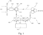
- a wind turbine generator 100 involving a DFIG 104 is depicted. As seen in Fig. 1 the rotor 106 of the DFIG 104 is coupled to a set of rotor blades 102 via an optional gearbox 103. The rotor blades 102 rotate in response to incoming wind power 101.
- the DFIG 104 is adapted to deliver power to the power grid 112 via an optional grid transformer 111 via two three phase branches 113, 114 and 115.
- power is delivered from the stator 105 of the DFIG 104 to the optional grid transformer 111.
- the other of the two three phase branches 113, 114 further comprises a frequency power converter involving a rotor-side AC/DC inverter 107 and a grid-side DC/AC inverter 108 being separated by an intermediate DC link 109.
- the rotor-side AC/DC inverter 107 and the grid-side DC/AC inverter 108 is controlled by a power controller 110. Power may flow in both directions in the three phase branches 113, 114.
- the wind turbine generator 100 is typically operated in a so-called power mode where the amount of active and reactive power to be delivered to the power grid 112 is set by respective active and reactive power references.
- the abnormal power grid event may involve an LVRT, an UVRT, an OVRT or an HVRT event.
- the grid voltage may in principle drop to any voltage level between 0 and 100% of the nominal grid voltage level.
- the grid voltage may in principle take any voltage level above the nominal grid voltage level.
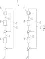
- Fig. 2 two closed control loops 200 are depicted.
- the upper closed control loop controls the d-axis rotor voltage 204 and thereby the reactive rotor current
- the lower closed control loop controls the q-axis rotor voltage 211 and thereby the active rotor current.
- a reactive current reference I Qref is provided to the left.
- This reactive current reference is compared to a total reactive current 205 being provided by the stator of the DFIG 207 and the grid-side inverter (not shown).
- the difference between the reactive current reference, I Qref , and the measured or determined total reactive current 205 is provided to the regulator 201 (reactive current regulator) which generates a reactive rotor reference 203.
- the reactive rotor reference 203 is compared to a measured or determined reactive rotor current 206 and the difference between them is provided to the regulator 202 (reactive current rotor controller) which generates the d-axis rotor voltage 204.
- the regulator 202 reactive current rotor controller
- I Pref active current rotor controller
- This active current reference is compared to a total active current 212 being provided by the stator of the DFIG 214 and the grid-side inverter (not shown).
- the difference between the active current reference, I Pref , and the measured or determined total active current 212 is provided to the regulator 208 (active current regulator) which generates an active rotor reference 210.
- the active rotor reference 210 is compared to a measured or determined active rotor current 213 and the difference between them is provided to the regulator 209 (active current rotor controller) which generates the q-axis rotor voltage 211.
- the regulators 201, 202, 208 and 209 may in principle be of any type, such as for example PI, PD or PID.
- the DFIG 207, 214 is controlled in a closed loop current configuration where current input references I Qref and I Pref are provided for the reactive and active current loops, respectively.
- a flow-chart 300 illustrating aspects of the method according to the present invention is depicted.
- the wind turbine generator is operated in a power mode.
- the wind turbine generator is operated in a current mode.
- the total active DFIG current 301 as well as the active rotor current 302 are measured, or determined, and a resulting q-axis rotor voltage 303 is generated.
- the total reactive DFIG current 304 as well as the reactive rotor current 305 are measured, or determined, and a resulting d-axis rotor voltage 306 is generates.
- the generated q-axis and d-axis rotor voltages 303, 306 are provided to the DFIG as long as the abnormal power grid event is present.
- the method illustrated in Fig. 3 may be implemented using variable means, such as a pure software implementation.
Landscapes
- Engineering & Computer Science (AREA)
- Power Engineering (AREA)
- Life Sciences & Earth Sciences (AREA)
- Sustainable Development (AREA)
- Sustainable Energy (AREA)
- Chemical & Material Sciences (AREA)
- Combustion & Propulsion (AREA)
- Mechanical Engineering (AREA)
- General Engineering & Computer Science (AREA)
- Control Of Eletrric Generators (AREA)
Description
- Aspects of the present invention relate to a wind turbine generator and a method for controlling an amount of power to be delivered from a wind turbine generator to a power grid during an abnormal power grid event.
- During an abnormal power grid event, it may be advantageous to maintain delivery of both active and reactive power to the power grid. In order to comply with this, the power producing units, such as wind turbine generators, coupled to the power grid should remain connected thereto.
-
CN201410305648 - Scientific paper, "Coordinated fault-ride-through strategy for doubly-fed induction generators with enhanced reactive and active power support" by Sumei Liu, Tianshu Bi, published in IET Renew. Power Gener., 2016, Vol. 10, Iss. 2, pp. 203-211, discloses: With the fault ride through (FRT) requirement of grid codes, wind generators must stay connected and provide the reactive and active power support during and after the grid faults. The doubly fed induction generators (DFIGs) usually employ an active rotor crowbar to ride-through the faults. The solution works well to protect the DFIG itself, but it has shortcomings in the power support. In the paper, a coordinated FRT control strategy is investigated to improve the power support capability of the DFIGs under the fault conditions. In this strategy, a seamless switch is designed to resume the power control mode after the short-term crowbar interruption. Additional compensation terms are inserted into the converter's control loops to relieve the side-effect of rotor transient current. The coordinated control of dc-chopper circuit and rotor-side converters is proposed to keep the dc-link voltage within its acceptable range. Moreover, a novel voltage limiter is designed with consideration of the conflicting effect of rotor transient current, converter's rating constraints and desired power goals. Compared with the conventional crowbar-based strategies, the proposed strategy can fully utilise the DFIG's potential to generate reactive and active power effectively. These performances have been demonstrated through the simulation and experimental tests.
- During normal power grid conditions, wind turbine generators are typically operated in a so-called power mode. Upon detection of an abnormal power grid event the power mode operation is typically disabled and replaced by a so-called current mode operation.
- In known arrangements, the current mode operation is implemented by delivering active and reactive currents to the power grid in a feed-forward implementation, i.e. in an open control loop implementation. It is well established that control systems which have only feed-forward behavior respond to input/control signals in a pre-defined manner without responding to how the loads on the control systems react. This may be disadvantageous when implemented for a control system of a doubly-fed induction generator (DFIG), e.g., where the rotor current references are to be set accurately.
- It may be seen as an object of embodiments of the present invention to provide a method and a wind turbine generator that facilitate that a more accurate rotor current reference may be provided during an abnormal power grid event.
- The above-mentioned object is complied with by providing, in a first aspect, a method for controlling an amount of power to be delivered from a wind turbine generator to a power grid during an abnormal power grid event, according to claim 1.
- In the present disclosure the abnormal power grid event involves a voltage change on the power grid, such as in connection with a low-voltage ride through (LVRT) event, an undervoltage ride through (UVRT) event, an over-voltage ride through (OVRT) event or a high-voltage ride through (HVRT) event, where the wind turbine generator remains connected to the power grid in order to support the power grid during the abnormal power grid event.
- The step of the detecting that an abnormal power grid event has occurred may involve detection of a grid voltage change. In case of an LVRT or a UVRT event, the grid voltage may in principle drop to any voltage level between 0 and 100% of the nominal grid voltage level. In case of an OVRT or an HVRT event, the grid voltage may in principle take any voltage level above the nominal grid voltage level.
- The voltage change may be measured using one or more software controlled voltage sensors connected to one or more phases.
- The duration of an abnormal power grid event may typically vary from a fraction of a second to perhaps several minutes depending on the type of abnormality. Before and after an abnormal power grid event the wind turbine generator may be operated in a power mode, whereas during the abnormal power grid events, such as an LVRT, an UVRT, an OVRT or an HVRT event, the wind turbine generator is operated according to embodiments of the method according to the present invention.
- The measured or determined total active current and the measured or determined total reactive current may comprise respective active and reactive current contributions from both the stator and rotor currents of a generator of the wind turbine generator.
- When an abnormal power grid event has been detected the method may further comprise the step of enabling an active current regulator and a reactive current regulator. The active current regulator as well as the reactive current regulator may form part of respective outer closed control loops where the measured or determined total active current and the measured or determined total reactive current may form the respective feedback signals.
- The active and reactive current regulators may in principle be any kind of regulators, including PI, PD, PID regulators or combinations thereof.
- In the outer closed control loop for active current control the measured or determined total active current may be subtracted from an active current reference so as to form an input signal to the active current regulator. Similarly, in the outer closed control loop for reactive current control the measured or determined total reactive current is subtracted from a reactive current reference so as to form an input signal to the reactive current regulator.
- The active current regulator may provide an active rotor reference signal that may form at least a portion of a control signal to an active current rotor controller which may form part of an inner closed control loop for active current control. In the inner closed control loop for active current control a measured or determined active rotor current may be subtracted from the active rotor reference signal provided by the active current regulator so as to form an input signal to the active current rotor controller.
- Similarly, the reactive current regulator may provide a reactive rotor reference signal that may form at least a portion of a control signal to a reactive current rotor controller which may form part of an inner closed control loop for reactive current control. In the inner closed control loop for reactive current control a measured or determined reactive rotor current may be subtracted from the reactive rotor reference signal provided by the reactive current regulator so as to form an input signal to the reactive current rotor controller.
- The active current rotor controller may be arranged to generate a q-axis rotor voltage, whereas the reactive current rotor controller may be adapted to generate a d-axis rotor voltage.
- Embodiments of the method according to the present invention may further comprise the step of disabling the active and reactive current regulators when then abnormal power grid event is no longer present. With the disabling of the active and reactive current regulators the wind turbine generator may return to power operation.
- The generator of the wind turbine generator may be a doubly-fed induction generator (DFIG).
- However, other types of generators may be applicable as well.
- In a second aspect, the present invention relates to a wind turbine generator comprising a power controller for controlling an amount of power to be delivered to a power grid during an abnormal power grid event, according to claim 10.
- Again, the abnormal power grid event involves a voltage drop on the power grid, such as in connection with an LVRT, an UVRT, an OVRT or an HVRT event, where the wind turbine generator remains connected to the power grid in order to support the power grid during the abnormal power grid event. The generator of the wind turbine generator may comprise DFIG. The detector for detecting that an abnormal power grid event has occurred may involve one or more software controlled voltage sensors capable of detecting when the grid voltage changes. In case of an LVRT or a UVRT event the grid voltage may in principle drop to any voltage level between 0 and 100% of the nominal grid voltage level. In case of an OVRT or an HVRT event the grid voltage may in principle take any voltage level above the nominal grid voltage level. The voltage changes may be detected in one or more phases.
- As previously addresses the duration of an abnormal power grid event may typically vary from a fraction of a second to several minutes. Before and after an abnormal power grid event the wind turbine generator may be operated in a power mode, whereas during the abnormal power grid events, such as an LVRT, an UVRT, an OVRT or an HVRT event, the wind turbine generator is operated according to embodiments of the method of the first aspect of the present invention.
- The first closed control loop may comprise an outer active closed control loop comprising an active current regulator, and an inner active closed control loop comprising an active current rotor controller, and wherein the active current regulator provides at least a portion of a control signal to the active current rotor controller. As part of the outer active closed control loop a measured or determined total active current may be subtracted from an active current reference so as to form an input signal to the active current regulator. As part of the inner active closed control loop a measured or determined active rotor current may be subtracted from an active rotor reference provided by the active current regulator so as to form an input signal to the active current rotor controller.
- Similarly, the second closed control loop may comprise an outer reactive closed control loop comprising a reactive current regulator, and an inner reactive closed control loop comprising a reactive current rotor controller, and wherein the reactive current regulator provides at least a portion of a control signal to the reactive current rotor controller. As part of the outer reactive closed control loop a measured or determined total reactive current may be subtracted from a reactive current reference so as to form an input signal to the reactive current regulator. As part of the inner reactive closed control loop a measured or determined reactive rotor current may be subtracted from a reactive rotor reference provided by the reactive current regulator so as to form an input signal to the reactive current rotor controller.
- The present invention will now be described in further details by way of embodiments and with reference to the accompanying figures, wherein
-
Fig. 1 schematically shows a wind turbine generator applying a doubly-fed induction generator, -
Fig. 2 schematically shows closed control loops for controlling the active and reactive currents during an abnormal power grid event, and -
Fig. 3 shows a flow-chart schematically illustrating the method according to aspects of the present invention. - While the invention is susceptible to various modifications and alternative forms specific embodiments have been shown by way of examples in the drawings and will be described in details herein. It should be understood, however, that the invention is not intended to be limited to the particular forms disclosed. Rather, the invention is to cover all modifications, and alternatives falling within the scope of the invention as defined by the appended claims.
- An aspect of the present invention relates to a method for operating a wind turbine generator during an abnormal power grid event, such as during a power grid voltage change including an LVRT event, an UVRT event, an OVRT event or an HVRT event. When an abnormal power grid event is detected the operation of the wind turbine generator is shifted from a power mode to a current mode. After the abnormal power grid event operation is resumed in power mode. Referring now to
Fig. 1 awind turbine generator 100 involving aDFIG 104 is depicted. As seen inFig. 1 therotor 106 of theDFIG 104 is coupled to a set ofrotor blades 102 via anoptional gearbox 103. Therotor blades 102 rotate in response toincoming wind power 101. TheDFIG 104 is adapted to deliver power to the power grid 112 via anoptional grid transformer 111 via two threephase branches phase branches 115 power is delivered from thestator 105 of theDFIG 104 to theoptional grid transformer 111. The other of the two threephase branches DC inverter 107 and a grid-side DC/AC inverter 108 being separated by anintermediate DC link 109. The rotor-side AC/DC inverter 107 and the grid-side DC/AC inverter 108 is controlled by apower controller 110. Power may flow in both directions in the threephase branches - During normal operation the
wind turbine generator 100 is typically operated in a so-called power mode where the amount of active and reactive power to be delivered to the power grid 112 is set by respective active and reactive power references. - As addressed above the abnormal power grid event may involve an LVRT, an UVRT, an OVRT or an HVRT event. In case of an LVRT or a UVRT event, the grid voltage may in principle drop to any voltage level between 0 and 100% of the nominal grid voltage level. In case of an OVRT or an HVRT event, the grid voltage may in principle take any voltage level above the nominal grid voltage level. When an abnormal power grid event has been detected the power mode is disabled and the wind turbine generator is reconfigured to be operable in a so-called total current mode. This implies that two current control loops - one active current control loop and one reactive current control loop - are established, cf.
Fig. 2 . - Referring now to
Fig. 2 twoclosed control loops 200 are depicted. The upper closed control loop controls the d-axis rotor voltage 204 and thereby the reactive rotor current, whereas the lower closed control loop controls the q-axis rotor voltage 211 and thereby the active rotor current. Referring now to the upper reactive control loop a reactive current reference IQref is provided to the left. This reactive current reference is compared to a total reactive current 205 being provided by the stator of theDFIG 207 and the grid-side inverter (not shown). The difference between the reactive current reference, IQref, and the measured or determined total reactive current 205 is provided to the regulator 201 (reactive current regulator) which generates areactive rotor reference 203. Thereactive rotor reference 203 is compared to a measured or determined reactive rotor current 206 and the difference between them is provided to the regulator 202 (reactive current rotor controller) which generates the d-axis rotor voltage 204. Referring now to the lower active control loop an active current reference IPref is provided to the left. This active current reference is compared to a total active current 212 being provided by the stator of theDFIG 214 and the grid-side inverter (not shown). The difference between the active current reference, IPref, and the measured or determined total active current 212 is provided to the regulator 208 (active current regulator) which generates anactive rotor reference 210. Theactive rotor reference 210 is compared to a measured or determined active rotor current 213 and the difference between them is provided to the regulator 209 (active current rotor controller) which generates the q-axis rotor voltage 211. Theregulators DFIG - In
Fig. 3 a flow-chart 300 illustrating aspects of the method according to the present invention is depicted. As depicted inFig. 3 if no abnormal power grid event is detected, i.e. if no grid fault is detected, the wind turbine generator is operated in a power mode. On the contrary, if an abnormal power grid event is detected the wind turbine generator is operated in a current mode. In the current mode the total active DFIG current 301 as well as the active rotor current 302 are measured, or determined, and a resulting q-axis rotor voltage 303 is generated. Similarly, the total reactive DFIG current 304 as well as the reactive rotor current 305 are measured, or determined, and a resulting d-axis rotor voltage 306 is generates. The generated q-axis and d-axis rotor voltages Fig. 3 may be implemented using variable means, such as a pure software implementation.
Claims (13)
- A method for controlling an amount of power to be delivered from a wind turbine generator (100) to a power grid (112) during an abnormal power grid event, the method comprising the steps of1) detecting an abnormal power grid event, wherein the abnormal power grid event involves a voltage change on the power grid;2) shifting operation of the wind turbine generator (100) from a power mode to a current mode (300); and3) controlling an active current (IPREF) delivered to the power grid (112) in response to a measured or determined total active current (212), wherein the step of controlling the active current comprises- an outer active closed control loop comprising an active current regulator (208), and- an inner active closed control loop comprising an active current rotor controller (209),wherein the active current regulator provides at least a portion of a control signal to the active current rotor controller; and4) controlling a reactive current (IQref) delivered to the power grid (112) in response to a measured or determined total reactive current (205) wherein the step of controlling the reactive current comprises- an outer reactive closed control loop comprising a reactive current regulator (201), and- an inner reactive closed control loop comprising a reactive current rotor controller (202),wherein the reactive current regulator provides at least a portion of a control signal to the reactive current rotor controller.
- A method according to claim 1, wherein the measured or determined total active current (212) and the measured or determined total reactive current (205) comprise respective active and reactive current contributions from both stator and rotor currents of an electrical generator (104) of the wind turbine generator (100).
- A method according to any of claims 1-2, further comprising the step of enabling an active current regulator (208) and a reactive current regulator (201).
- A method according to claim 3, wherein the measured or determined total active current is subtracted from an active current reference so as to form an input signal to the active current regulator.
- A method according to claim 4, wherein the active current regulator (208) provides at least a portion of a control signal to an active current rotor controller (209).
- A method according to any of claims 3-5, wherein the measured or determined total reactive current is subtracted from a reactive current reference so as to form an input signal to the reactive current regulator.
- A method according to claim 6, wherein the reactive current regulator (201) provides at least a portion of a control signal to a reactive current rotor controller (202).
- A method according to any of claims 3 to 7, further comprising the step of disabling the active and reactive current regulators when the abnormal power grid event is no longer present.
- A method according to any of the preceding claims, wherein the wind turbine generator comprises a doubly-fed induction generator.
- A wind turbine generator (100) comprising a power controller for controlling an amount of power to be delivered to a power grid (112) during an abnormal power grid event, the power controller comprising1) a detector for detecting an abnormal power grid event, wherein the abnormal power grid event involves a voltage change on the power grid;2) an operation shift of the wind turbine generator (100) from a power mode to a current mode (300); and3) a first closed control loop for controlling an active current (212) delivered to the power grid, the first closed control loop comprises- an outer active closed control loop comprising an active current regulator (208), and- an inner active closed control loop comprising an active current rotor controller (209)wherein the active current regulator provides at least a portion of a control signal to the active current rotor controller; and4) a second closed control loop for controlling a reactive current (205) delivered to the power grid (112) the second closed control loop comprises- an outer reactive closed control loop comprising a reactive current regulator (201), and- an inner reactive closed control loop comprising a reactive current rotor controller (202)wherein the reactive current regulator provides at least a portion of a control signal to the reactive current rotor controller.
- A wind turbine generator according to claim 10, wherein a measured or determined total active current is subtracted from an active current reference so as to form an input signal to the active current regulator.
- A wind turbine generator according to claim 10, wherein a measured or determined total reactive current is subtracted from a reactive current reference so as to form an input signal to the reactive current regulator.
- A wind turbine generator according to any of claims 10-12, wherein the wind turbine generator comprises a doubly-fed induction generator.
Applications Claiming Priority (2)
| Application Number | Priority Date | Filing Date | Title |
|---|---|---|---|
| DKPA201670354 | 2016-05-25 | ||
| PCT/DK2017/050156 WO2017202428A1 (en) | 2016-05-25 | 2017-05-16 | Operating a wind turbine generator during an abnormal grid event |
Publications (2)
| Publication Number | Publication Date |
|---|---|
| EP3464889A1 EP3464889A1 (en) | 2019-04-10 |
| EP3464889B1 true EP3464889B1 (en) | 2022-12-14 |
Family
ID=58992582
Family Applications (1)
| Application Number | Title | Priority Date | Filing Date |
|---|---|---|---|
| EP17727097.2A Active EP3464889B1 (en) | 2016-05-25 | 2017-05-16 | Operating a wind turbine generator during an abnormal grid event |
Country Status (5)
| Country | Link |
|---|---|
| US (1) | US10855082B2 (en) |
| EP (1) | EP3464889B1 (en) |
| CN (1) | CN109154275B (en) |
| ES (1) | ES2934220T3 (en) |
| WO (1) | WO2017202428A1 (en) |
Families Citing this family (6)
| Publication number | Priority date | Publication date | Assignee | Title |
|---|---|---|---|---|
| WO2017202428A1 (en) | 2016-05-25 | 2017-11-30 | Vestas Wind Systems A/S | Operating a wind turbine generator during an abnormal grid event |
| EP3563477A1 (en) * | 2016-12-27 | 2019-11-06 | Vestas Wind Systems A/S | Control system for modular multilevel converter |
| US11434871B2 (en) | 2018-01-25 | 2022-09-06 | Vestas Wind Systems A/S | Black start restoration |
| US10826297B2 (en) * | 2018-11-06 | 2020-11-03 | General Electric Company | System and method for wind power generation and transmission in electrical power systems |
| EP3922841A1 (en) * | 2020-06-10 | 2021-12-15 | Siemens Gamesa Renewable Energy A/S | Wind turbine operational method for responding to grid disturbance |
| US12278589B2 (en) * | 2020-12-08 | 2025-04-15 | Beijing Goldwind Science & Creation Windpower Equipment Co., Ltd. | Control method and control apparatus of permanent magnet generator |
Citations (1)
| Publication number | Priority date | Publication date | Assignee | Title |
|---|---|---|---|---|
| CN104113077B (en) * | 2014-06-30 | 2016-01-20 | 浙江大学 | A kind of control method for coordinating of dual-feed asynchronous wind power generator high voltage crossing |
Family Cites Families (20)
| Publication number | Priority date | Publication date | Assignee | Title |
|---|---|---|---|---|
| US6566764B2 (en) | 2000-05-23 | 2003-05-20 | Vestas Wind Systems A/S, R&D | Variable speed wind turbine having a matrix converter |
| CN101401294B (en) * | 2006-03-17 | 2013-04-17 | 英捷电力技术有限公司 | Variable speed wind turbine having an exciter machine and a power converter not connected to the grid |
| EP2070175B1 (en) | 2006-10-02 | 2016-12-07 | Vestas Wind Systems A/S | Method for operating a wind turbine connected to a utility grid during utility grid disturbance, wind turbine and wind park |
| DE602007009966D1 (en) * | 2007-07-16 | 2010-12-02 | Gamesa Innovation & Tech Sl | Wind power system and operating method therefor |
| CA2774401C (en) * | 2009-09-18 | 2019-01-15 | Queen's University At Kingston | Distributed power generation interface |
| US9236742B2 (en) * | 2010-02-25 | 2016-01-12 | Vestas Wind Systems A/S | Method and control arrangement for controlling a reactive power source |
| US9306395B2 (en) * | 2010-02-25 | 2016-04-05 | Vestas Wind Systems A/S | Wind turbine controller applying differential pole control algorithm |
| CN102082543B (en) | 2010-10-28 | 2012-05-23 | 天津大学 | Method for controlling double-feed wind driven generator under imbalanced power grid voltage |
| JP5627529B2 (en) | 2011-04-01 | 2014-11-19 | 三菱重工業株式会社 | Wind turbine generator control device, wind turbine generator, wind farm, and wind turbine generator control method |
| JP5957094B2 (en) * | 2012-12-27 | 2016-07-27 | 川崎重工業株式会社 | Combined power generation system with power conversion device |
| EP2871743B1 (en) * | 2013-11-11 | 2017-08-30 | Siemens Aktiengesellschaft | A wind turbine, a wind park and operating methods thereof |
| JP6243801B2 (en) * | 2014-06-12 | 2017-12-06 | 株式会社日立製作所 | Power converter |
| CN104362668B (en) * | 2014-10-16 | 2016-08-24 | 中国人民解放军装甲兵工程学院 | The control method of double-fed wind power generator during a kind of Voltage unbalance/harmonic distortion |
| US9543859B2 (en) * | 2015-01-23 | 2017-01-10 | Suzan EREN | System and method for active/reactive power compensation |
| CN105098834B (en) | 2015-08-12 | 2018-02-13 | 国网山东省电力公司潍坊供电公司 | A voltage control method for different working conditions and different modes for doubly-fed wind farms |
| WO2017118460A1 (en) * | 2016-01-06 | 2017-07-13 | Vestas Wind Systems A/S | Control of a wind power plant |
| ES2983127T3 (en) * | 2016-01-29 | 2024-10-21 | Siemens Gamesa Renewable Energy As | Operating a wind turbine on a wind farm |
| WO2017202428A1 (en) | 2016-05-25 | 2017-11-30 | Vestas Wind Systems A/S | Operating a wind turbine generator during an abnormal grid event |
| JP6809753B2 (en) * | 2016-12-28 | 2021-01-06 | 川崎重工業株式会社 | Combined cycle system |
| CN109378860B (en) | 2018-12-14 | 2021-01-29 | 重庆大学 | Low voltage ride through control method for double-fed wind power generation system |
-
2017
- 2017-05-16 WO PCT/DK2017/050156 patent/WO2017202428A1/en not_active Ceased
- 2017-05-16 ES ES17727097T patent/ES2934220T3/en active Active
- 2017-05-16 EP EP17727097.2A patent/EP3464889B1/en active Active
- 2017-05-16 US US16/099,608 patent/US10855082B2/en active Active
- 2017-05-16 CN CN201780032104.2A patent/CN109154275B/en active Active
Patent Citations (1)
| Publication number | Priority date | Publication date | Assignee | Title |
|---|---|---|---|---|
| CN104113077B (en) * | 2014-06-30 | 2016-01-20 | 浙江大学 | A kind of control method for coordinating of dual-feed asynchronous wind power generator high voltage crossing |
Non-Patent Citations (1)
| Title |
|---|
| LIU SUMEI ET AL: "Coordinated fault-ride-through strategy for doubly-fed induction generators with enhanced reactive and active power support", IET RENEWABLE POWER GENERATION, THE INSTITUTION OF ENGINEERING AND TECHNOLOGY, MICHAEL FARADAY HOUSE, SIX HILLS WAY, STEVENAGE, HERTS. SG1 2AY, UK, vol. 10, no. 2, 1 February 2016 (2016-02-01), pages 203 - 211, XP006055150, ISSN: 1752-1416, DOI: 10.1049/IET-RPG.2015.0003 * |
Also Published As
| Publication number | Publication date |
|---|---|
| US20190148949A1 (en) | 2019-05-16 |
| CN109154275A (en) | 2019-01-04 |
| CN109154275B (en) | 2021-01-26 |
| EP3464889A1 (en) | 2019-04-10 |
| WO2017202428A1 (en) | 2017-11-30 |
| US10855082B2 (en) | 2020-12-01 |
| ES2934220T3 (en) | 2023-02-20 |
Similar Documents
| Publication | Publication Date | Title |
|---|---|---|
| EP2859638B1 (en) | Wind-power-plant control upon low-voltage grid faults | |
| EP2221936B1 (en) | System and method for control of a grid connected power generating system | |
| US10704534B2 (en) | Fault ride through method for load impact minimization | |
| US9551323B2 (en) | Power plant control during a low voltage or a high voltage event | |
| US8615331B2 (en) | Method and apparatus for controlling the feed of reactive power in a wind power generation system | |
| EP3371882B1 (en) | Balancing reactive current between a dfig stator and a grid-side inverter | |
| US10855082B2 (en) | Operating a wind turbine generator during an abnormal grid event | |
| US20160084229A1 (en) | Method and control arrangement for controlling a reactive power source | |
| US20140307488A1 (en) | Controller for controlling a power converter | |
| US20150300318A1 (en) | Fast run-back control including plant losses | |
| EP3633847B1 (en) | A method for handling sub-synchronous resonances | |
| Korai et al. | New control approach for blackstart capability of full converter wind turbines with direct voltage control | |
| Hazari et al. | A new fuzzy logic based control strategy for variable speed wind generator to enhance the transient stability of fixed speed wind generator | |
| JP5401383B2 (en) | Wind power generation system and control device therefor | |
| JP2018007458A (en) | Wind power generation equipment, operation method thereof, and wind farm | |
| Guo et al. | Active power limit for DFIG-based wind turbine under weak grid | |
| Alizadeh et al. | Improving Analysis of Low Voltage Ride Through Capability in Turbines Connected to The Brushless Doubly Fed Induction Generator (BDFIG) under Fault Conditions | |
| Simon et al. | Transient modeling and control of dfig with fault ride through capability | |
| Loulijat et al. | El marghichi | |
| Hongwei et al. | Direct power control of DFIG wind turbines for low voltage ride-through | |
| Gunalan et al. | A new control strategy to enhance LVRT for doubly fed induction generator | |
| Ramsumar | The control of power electronic converters for grid code compliance in wind energy generation systems | |
| CN122029717A (en) | System and method for providing black start of grid formed inverter-based resources |
Legal Events
| Date | Code | Title | Description |
|---|---|---|---|
| STAA | Information on the status of an ep patent application or granted ep patent |
Free format text: STATUS: UNKNOWN |
|
| STAA | Information on the status of an ep patent application or granted ep patent |
Free format text: STATUS: THE INTERNATIONAL PUBLICATION HAS BEEN MADE |
|
| PUAI | Public reference made under article 153(3) epc to a published international application that has entered the european phase |
Free format text: ORIGINAL CODE: 0009012 |
|
| STAA | Information on the status of an ep patent application or granted ep patent |
Free format text: STATUS: REQUEST FOR EXAMINATION WAS MADE |
|
| 17P | Request for examination filed |
Effective date: 20181112 |
|
| AK | Designated contracting states |
Kind code of ref document: A1 Designated state(s): AL AT BE BG CH CY CZ DE DK EE ES FI FR GB GR HR HU IE IS IT LI LT LU LV MC MK MT NL NO PL PT RO RS SE SI SK SM TR |
|
| AX | Request for extension of the european patent |
Extension state: BA ME |
|
| DAV | Request for validation of the european patent (deleted) | ||
| DAX | Request for extension of the european patent (deleted) | ||
| STAA | Information on the status of an ep patent application or granted ep patent |
Free format text: STATUS: EXAMINATION IS IN PROGRESS |
|
| 17Q | First examination report despatched |
Effective date: 20210304 |
|
| GRAP | Despatch of communication of intention to grant a patent |
Free format text: ORIGINAL CODE: EPIDOSNIGR1 |
|
| STAA | Information on the status of an ep patent application or granted ep patent |
Free format text: STATUS: GRANT OF PATENT IS INTENDED |
|
| INTG | Intention to grant announced |
Effective date: 20220928 |
|
| GRAS | Grant fee paid |
Free format text: ORIGINAL CODE: EPIDOSNIGR3 |
|
| GRAA | (expected) grant |
Free format text: ORIGINAL CODE: 0009210 |
|
| STAA | Information on the status of an ep patent application or granted ep patent |
Free format text: STATUS: THE PATENT HAS BEEN GRANTED |
|
| AK | Designated contracting states |
Kind code of ref document: B1 Designated state(s): AL AT BE BG CH CY CZ DE DK EE ES FI FR GB GR HR HU IE IS IT LI LT LU LV MC MK MT NL NO PL PT RO RS SE SI SK SM TR |
|
| REG | Reference to a national code |
Ref country code: GB Ref legal event code: FG4D |
|
| REG | Reference to a national code |
Ref country code: CH Ref legal event code: EP |
|
| REG | Reference to a national code |
Ref country code: DE Ref legal event code: R096 Ref document number: 602017064578 Country of ref document: DE |
|
| REG | Reference to a national code |
Ref country code: IE Ref legal event code: FG4D |
|
| REG | Reference to a national code |
Ref country code: AT Ref legal event code: REF Ref document number: 1537802 Country of ref document: AT Kind code of ref document: T Effective date: 20230115 |
|
| REG | Reference to a national code |
Ref country code: ES Ref legal event code: FG2A Ref document number: 2934220 Country of ref document: ES Kind code of ref document: T3 Effective date: 20230220 |
|
| REG | Reference to a national code |
Ref country code: LT Ref legal event code: MG9D |
|
| REG | Reference to a national code |
Ref country code: NL Ref legal event code: MP Effective date: 20221214 |
|
| PG25 | Lapsed in a contracting state [announced via postgrant information from national office to epo] |
Ref country code: SE Free format text: LAPSE BECAUSE OF FAILURE TO SUBMIT A TRANSLATION OF THE DESCRIPTION OR TO PAY THE FEE WITHIN THE PRESCRIBED TIME-LIMIT Effective date: 20221214 Ref country code: NO Free format text: LAPSE BECAUSE OF FAILURE TO SUBMIT A TRANSLATION OF THE DESCRIPTION OR TO PAY THE FEE WITHIN THE PRESCRIBED TIME-LIMIT Effective date: 20230314 Ref country code: LT Free format text: LAPSE BECAUSE OF FAILURE TO SUBMIT A TRANSLATION OF THE DESCRIPTION OR TO PAY THE FEE WITHIN THE PRESCRIBED TIME-LIMIT Effective date: 20221214 Ref country code: FI Free format text: LAPSE BECAUSE OF FAILURE TO SUBMIT A TRANSLATION OF THE DESCRIPTION OR TO PAY THE FEE WITHIN THE PRESCRIBED TIME-LIMIT Effective date: 20221214 |
|
| REG | Reference to a national code |
Ref country code: AT Ref legal event code: MK05 Ref document number: 1537802 Country of ref document: AT Kind code of ref document: T Effective date: 20221214 |
|
| PG25 | Lapsed in a contracting state [announced via postgrant information from national office to epo] |
Ref country code: RS Free format text: LAPSE BECAUSE OF FAILURE TO SUBMIT A TRANSLATION OF THE DESCRIPTION OR TO PAY THE FEE WITHIN THE PRESCRIBED TIME-LIMIT Effective date: 20221214 Ref country code: LV Free format text: LAPSE BECAUSE OF FAILURE TO SUBMIT A TRANSLATION OF THE DESCRIPTION OR TO PAY THE FEE WITHIN THE PRESCRIBED TIME-LIMIT Effective date: 20221214 Ref country code: HR Free format text: LAPSE BECAUSE OF FAILURE TO SUBMIT A TRANSLATION OF THE DESCRIPTION OR TO PAY THE FEE WITHIN THE PRESCRIBED TIME-LIMIT Effective date: 20221214 Ref country code: GR Free format text: LAPSE BECAUSE OF FAILURE TO SUBMIT A TRANSLATION OF THE DESCRIPTION OR TO PAY THE FEE WITHIN THE PRESCRIBED TIME-LIMIT Effective date: 20230315 |
|
| P01 | Opt-out of the competence of the unified patent court (upc) registered |
Effective date: 20230521 |
|
| PG25 | Lapsed in a contracting state [announced via postgrant information from national office to epo] |
Ref country code: NL Free format text: LAPSE BECAUSE OF FAILURE TO SUBMIT A TRANSLATION OF THE DESCRIPTION OR TO PAY THE FEE WITHIN THE PRESCRIBED TIME-LIMIT Effective date: 20221214 |
|
| PG25 | Lapsed in a contracting state [announced via postgrant information from national office to epo] |
Ref country code: SM Free format text: LAPSE BECAUSE OF FAILURE TO SUBMIT A TRANSLATION OF THE DESCRIPTION OR TO PAY THE FEE WITHIN THE PRESCRIBED TIME-LIMIT Effective date: 20221214 Ref country code: RO Free format text: LAPSE BECAUSE OF FAILURE TO SUBMIT A TRANSLATION OF THE DESCRIPTION OR TO PAY THE FEE WITHIN THE PRESCRIBED TIME-LIMIT Effective date: 20221214 Ref country code: PT Free format text: LAPSE BECAUSE OF FAILURE TO SUBMIT A TRANSLATION OF THE DESCRIPTION OR TO PAY THE FEE WITHIN THE PRESCRIBED TIME-LIMIT Effective date: 20230414 Ref country code: EE Free format text: LAPSE BECAUSE OF FAILURE TO SUBMIT A TRANSLATION OF THE DESCRIPTION OR TO PAY THE FEE WITHIN THE PRESCRIBED TIME-LIMIT Effective date: 20221214 Ref country code: CZ Free format text: LAPSE BECAUSE OF FAILURE TO SUBMIT A TRANSLATION OF THE DESCRIPTION OR TO PAY THE FEE WITHIN THE PRESCRIBED TIME-LIMIT Effective date: 20221214 Ref country code: AT Free format text: LAPSE BECAUSE OF FAILURE TO SUBMIT A TRANSLATION OF THE DESCRIPTION OR TO PAY THE FEE WITHIN THE PRESCRIBED TIME-LIMIT Effective date: 20221214 |
|
| PG25 | Lapsed in a contracting state [announced via postgrant information from national office to epo] |
Ref country code: SK Free format text: LAPSE BECAUSE OF FAILURE TO SUBMIT A TRANSLATION OF THE DESCRIPTION OR TO PAY THE FEE WITHIN THE PRESCRIBED TIME-LIMIT Effective date: 20221214 Ref country code: PL Free format text: LAPSE BECAUSE OF FAILURE TO SUBMIT A TRANSLATION OF THE DESCRIPTION OR TO PAY THE FEE WITHIN THE PRESCRIBED TIME-LIMIT Effective date: 20221214 Ref country code: IS Free format text: LAPSE BECAUSE OF FAILURE TO SUBMIT A TRANSLATION OF THE DESCRIPTION OR TO PAY THE FEE WITHIN THE PRESCRIBED TIME-LIMIT Effective date: 20230414 Ref country code: AL Free format text: LAPSE BECAUSE OF FAILURE TO SUBMIT A TRANSLATION OF THE DESCRIPTION OR TO PAY THE FEE WITHIN THE PRESCRIBED TIME-LIMIT Effective date: 20221214 |
|
| REG | Reference to a national code |
Ref country code: DE Ref legal event code: R097 Ref document number: 602017064578 Country of ref document: DE |
|
| PLBE | No opposition filed within time limit |
Free format text: ORIGINAL CODE: 0009261 |
|
| STAA | Information on the status of an ep patent application or granted ep patent |
Free format text: STATUS: NO OPPOSITION FILED WITHIN TIME LIMIT |
|
| PG25 | Lapsed in a contracting state [announced via postgrant information from national office to epo] |
Ref country code: DK Free format text: LAPSE BECAUSE OF FAILURE TO SUBMIT A TRANSLATION OF THE DESCRIPTION OR TO PAY THE FEE WITHIN THE PRESCRIBED TIME-LIMIT Effective date: 20221214 |
|
| 26N | No opposition filed |
Effective date: 20230915 |
|
| PG25 | Lapsed in a contracting state [announced via postgrant information from national office to epo] |
Ref country code: SI Free format text: LAPSE BECAUSE OF FAILURE TO SUBMIT A TRANSLATION OF THE DESCRIPTION OR TO PAY THE FEE WITHIN THE PRESCRIBED TIME-LIMIT Effective date: 20221214 |
|
| REG | Reference to a national code |
Ref country code: CH Ref legal event code: PL |
|
| PG25 | Lapsed in a contracting state [announced via postgrant information from national office to epo] |
Ref country code: MC Free format text: LAPSE BECAUSE OF FAILURE TO SUBMIT A TRANSLATION OF THE DESCRIPTION OR TO PAY THE FEE WITHIN THE PRESCRIBED TIME-LIMIT Effective date: 20221214 |
|
| REG | Reference to a national code |
Ref country code: BE Ref legal event code: MM Effective date: 20230531 |
|
| PG25 | Lapsed in a contracting state [announced via postgrant information from national office to epo] |
Ref country code: MC Free format text: LAPSE BECAUSE OF FAILURE TO SUBMIT A TRANSLATION OF THE DESCRIPTION OR TO PAY THE FEE WITHIN THE PRESCRIBED TIME-LIMIT Effective date: 20221214 Ref country code: LU Free format text: LAPSE BECAUSE OF NON-PAYMENT OF DUE FEES Effective date: 20230516 Ref country code: LI Free format text: LAPSE BECAUSE OF NON-PAYMENT OF DUE FEES Effective date: 20230531 Ref country code: CH Free format text: LAPSE BECAUSE OF NON-PAYMENT OF DUE FEES Effective date: 20230531 |
|
| REG | Reference to a national code |
Ref country code: IE Ref legal event code: MM4A |
|
| PG25 | Lapsed in a contracting state [announced via postgrant information from national office to epo] |
Ref country code: IE Free format text: LAPSE BECAUSE OF NON-PAYMENT OF DUE FEES Effective date: 20230516 |
|
| PG25 | Lapsed in a contracting state [announced via postgrant information from national office to epo] |
Ref country code: IE Free format text: LAPSE BECAUSE OF NON-PAYMENT OF DUE FEES Effective date: 20230516 |
|
| PG25 | Lapsed in a contracting state [announced via postgrant information from national office to epo] |
Ref country code: IT Free format text: LAPSE BECAUSE OF FAILURE TO SUBMIT A TRANSLATION OF THE DESCRIPTION OR TO PAY THE FEE WITHIN THE PRESCRIBED TIME-LIMIT Effective date: 20221214 Ref country code: BE Free format text: LAPSE BECAUSE OF NON-PAYMENT OF DUE FEES Effective date: 20230531 |
|
| PG25 | Lapsed in a contracting state [announced via postgrant information from national office to epo] |
Ref country code: BG Free format text: LAPSE BECAUSE OF FAILURE TO SUBMIT A TRANSLATION OF THE DESCRIPTION OR TO PAY THE FEE WITHIN THE PRESCRIBED TIME-LIMIT Effective date: 20221214 |
|
| PG25 | Lapsed in a contracting state [announced via postgrant information from national office to epo] |
Ref country code: BG Free format text: LAPSE BECAUSE OF FAILURE TO SUBMIT A TRANSLATION OF THE DESCRIPTION OR TO PAY THE FEE WITHIN THE PRESCRIBED TIME-LIMIT Effective date: 20221214 |
|
| PGFP | Annual fee paid to national office [announced via postgrant information from national office to epo] |
Ref country code: DE Payment date: 20250528 Year of fee payment: 9 |
|
| PGFP | Annual fee paid to national office [announced via postgrant information from national office to epo] |
Ref country code: ES Payment date: 20250611 Year of fee payment: 9 |
|
| PGFP | Annual fee paid to national office [announced via postgrant information from national office to epo] |
Ref country code: FR Payment date: 20250526 Year of fee payment: 9 |
|
| PG25 | Lapsed in a contracting state [announced via postgrant information from national office to epo] |
Ref country code: CY Free format text: LAPSE BECAUSE OF FAILURE TO SUBMIT A TRANSLATION OF THE DESCRIPTION OR TO PAY THE FEE WITHIN THE PRESCRIBED TIME-LIMIT; INVALID AB INITIO Effective date: 20170516 |
|
| PG25 | Lapsed in a contracting state [announced via postgrant information from national office to epo] |
Ref country code: HU Free format text: LAPSE BECAUSE OF FAILURE TO SUBMIT A TRANSLATION OF THE DESCRIPTION OR TO PAY THE FEE WITHIN THE PRESCRIBED TIME-LIMIT; INVALID AB INITIO Effective date: 20170516 |
|
| PG25 | Lapsed in a contracting state [announced via postgrant information from national office to epo] |
Ref country code: TR Free format text: LAPSE BECAUSE OF FAILURE TO SUBMIT A TRANSLATION OF THE DESCRIPTION OR TO PAY THE FEE WITHIN THE PRESCRIBED TIME-LIMIT Effective date: 20221214 |
|
| PGFP | Annual fee paid to national office [announced via postgrant information from national office to epo] |
Ref country code: GB Payment date: 20260304 Year of fee payment: 10 |