EP3464837B1 - Actuation apparatus - Google Patents
Actuation apparatus Download PDFInfo
- Publication number
- EP3464837B1 EP3464837B1 EP17725253.3A EP17725253A EP3464837B1 EP 3464837 B1 EP3464837 B1 EP 3464837B1 EP 17725253 A EP17725253 A EP 17725253A EP 3464837 B1 EP3464837 B1 EP 3464837B1
- Authority
- EP
- European Patent Office
- Prior art keywords
- shaft
- valve train
- actuation
- switchable
- component
- Prior art date
- Legal status (The legal status is an assumption and is not a legal conclusion. Google has not performed a legal analysis and makes no representation as to the accuracy of the status listed.)
- Active
Links
Images




Classifications
-
- F—MECHANICAL ENGINEERING; LIGHTING; HEATING; WEAPONS; BLASTING
- F01—MACHINES OR ENGINES IN GENERAL; ENGINE PLANTS IN GENERAL; STEAM ENGINES
- F01L—CYCLICALLY OPERATING VALVES FOR MACHINES OR ENGINES
- F01L1/00—Valve-gear or valve arrangements, e.g. lift-valve gear
- F01L1/12—Transmitting gear between valve drive and valve
- F01L1/18—Rocking arms or levers
- F01L1/185—Overhead end-pivot rocking arms
-
- F—MECHANICAL ENGINEERING; LIGHTING; HEATING; WEAPONS; BLASTING
- F01—MACHINES OR ENGINES IN GENERAL; ENGINE PLANTS IN GENERAL; STEAM ENGINES
- F01L—CYCLICALLY OPERATING VALVES FOR MACHINES OR ENGINES
- F01L13/00—Modifications of valve-gear to facilitate reversing, braking, starting, changing compression ratio, or other specific operations
- F01L13/0015—Modifications of valve-gear to facilitate reversing, braking, starting, changing compression ratio, or other specific operations for optimising engine performances by modifying valve lift according to various working parameters, e.g. rotational speed, load, torque
-
- F—MECHANICAL ENGINEERING; LIGHTING; HEATING; WEAPONS; BLASTING
- F01—MACHINES OR ENGINES IN GENERAL; ENGINE PLANTS IN GENERAL; STEAM ENGINES
- F01L—CYCLICALLY OPERATING VALVES FOR MACHINES OR ENGINES
- F01L13/00—Modifications of valve-gear to facilitate reversing, braking, starting, changing compression ratio, or other specific operations
- F01L13/0015—Modifications of valve-gear to facilitate reversing, braking, starting, changing compression ratio, or other specific operations for optimising engine performances by modifying valve lift according to various working parameters, e.g. rotational speed, load, torque
- F01L13/0036—Modifications of valve-gear to facilitate reversing, braking, starting, changing compression ratio, or other specific operations for optimising engine performances by modifying valve lift according to various working parameters, e.g. rotational speed, load, torque the valves being driven by two or more cams with different shape, size or timing or a single cam profiled in axial and radial direction
-
- F—MECHANICAL ENGINEERING; LIGHTING; HEATING; WEAPONS; BLASTING
- F02—COMBUSTION ENGINES; HOT-GAS OR COMBUSTION-PRODUCT ENGINE PLANTS
- F02M—SUPPLYING COMBUSTION ENGINES IN GENERAL WITH COMBUSTIBLE MIXTURES OR CONSTITUENTS THEREOF
- F02M26/00—Engine-pertinent apparatus for adding exhaust gases to combustion-air, main fuel or fuel-air mixture, e.g. by exhaust gas recirculation [EGR] systems
- F02M26/01—Internal exhaust gas recirculation, i.e. wherein the residual exhaust gases are trapped in the cylinder or pushed back from the intake or the exhaust manifold into the combustion chamber without the use of additional passages
-
- F—MECHANICAL ENGINEERING; LIGHTING; HEATING; WEAPONS; BLASTING
- F01—MACHINES OR ENGINES IN GENERAL; ENGINE PLANTS IN GENERAL; STEAM ENGINES
- F01L—CYCLICALLY OPERATING VALVES FOR MACHINES OR ENGINES
- F01L1/00—Valve-gear or valve arrangements, e.g. lift-valve gear
- F01L1/20—Adjusting or compensating clearance
- F01L1/22—Adjusting or compensating clearance automatically, e.g. mechanically
-
- F—MECHANICAL ENGINEERING; LIGHTING; HEATING; WEAPONS; BLASTING
- F01—MACHINES OR ENGINES IN GENERAL; ENGINE PLANTS IN GENERAL; STEAM ENGINES
- F01L—CYCLICALLY OPERATING VALVES FOR MACHINES OR ENGINES
- F01L1/00—Valve-gear or valve arrangements, e.g. lift-valve gear
- F01L1/20—Adjusting or compensating clearance
- F01L1/22—Adjusting or compensating clearance automatically, e.g. mechanically
- F01L1/24—Adjusting or compensating clearance automatically, e.g. mechanically by fluid means, e.g. hydraulically
- F01L1/2405—Adjusting or compensating clearance automatically, e.g. mechanically by fluid means, e.g. hydraulically by means of a hydraulic adjusting device located between the cylinder head and rocker arm
-
- F—MECHANICAL ENGINEERING; LIGHTING; HEATING; WEAPONS; BLASTING
- F01—MACHINES OR ENGINES IN GENERAL; ENGINE PLANTS IN GENERAL; STEAM ENGINES
- F01L—CYCLICALLY OPERATING VALVES FOR MACHINES OR ENGINES
- F01L1/00—Valve-gear or valve arrangements, e.g. lift-valve gear
- F01L1/12—Transmitting gear between valve drive and valve
- F01L1/18—Rocking arms or levers
- F01L2001/186—Split rocking arms, e.g. rocker arms having two articulated parts and means for varying the relative position of these parts or for selectively connecting the parts to move in unison
-
- F—MECHANICAL ENGINEERING; LIGHTING; HEATING; WEAPONS; BLASTING
- F01—MACHINES OR ENGINES IN GENERAL; ENGINE PLANTS IN GENERAL; STEAM ENGINES
- F01L—CYCLICALLY OPERATING VALVES FOR MACHINES OR ENGINES
- F01L13/00—Modifications of valve-gear to facilitate reversing, braking, starting, changing compression ratio, or other specific operations
- F01L2013/10—Auxiliary actuators for variable valve timing
- F01L2013/103—Electric motors
-
- F—MECHANICAL ENGINEERING; LIGHTING; HEATING; WEAPONS; BLASTING
- F01—MACHINES OR ENGINES IN GENERAL; ENGINE PLANTS IN GENERAL; STEAM ENGINES
- F01L—CYCLICALLY OPERATING VALVES FOR MACHINES OR ENGINES
- F01L13/00—Modifications of valve-gear to facilitate reversing, braking, starting, changing compression ratio, or other specific operations
- F01L2013/10—Auxiliary actuators for variable valve timing
- F01L2013/105—Hydraulic motors
-
- F—MECHANICAL ENGINEERING; LIGHTING; HEATING; WEAPONS; BLASTING
- F01—MACHINES OR ENGINES IN GENERAL; ENGINE PLANTS IN GENERAL; STEAM ENGINES
- F01L—CYCLICALLY OPERATING VALVES FOR MACHINES OR ENGINES
- F01L13/00—Modifications of valve-gear to facilitate reversing, braking, starting, changing compression ratio, or other specific operations
- F01L2013/10—Auxiliary actuators for variable valve timing
- F01L2013/106—Pneumatic motors
-
- F—MECHANICAL ENGINEERING; LIGHTING; HEATING; WEAPONS; BLASTING
- F01—MACHINES OR ENGINES IN GENERAL; ENGINE PLANTS IN GENERAL; STEAM ENGINES
- F01L—CYCLICALLY OPERATING VALVES FOR MACHINES OR ENGINES
- F01L2305/00—Valve arrangements comprising rollers
Definitions
- the present invention relates to actuation, and more specifically actuation of components of switchable engine or valve train devices of an internal combustion engine.
- valve train assemblies may comprise a switchable rocker arm to provide for control of valve actuation by alternating between at least two or more modes of operation (e.g. valve-lift modes).
- Such rocker arms typically involve multiple bodies, such as an inner arm and an outer arm. These bodies are latched together to provide one mode of operation (e.g. a first valve-lift mode) and are unlatched, and hence can pivot with respect to each other, to provide a second mode of operation (e.g. a second valve-lift mode).
- a moveable latch pin is used and actuated and de-actuated to switch between the two modes of operation.
- WO 2013/156610 A1 discloses such a dual lift rocker arm with a moveable latch pin.
- the default position of the latch pin is unlatched, and it is retained in this position using biasing means.
- the latch pin is actuated to the latched position using an external actuation mechanism based on a leaf spring.
- the leaf spring is controlled to rotate a certain amount so as to engage with a roller of the latch pin, and hence push the latch pin into the latched position.
- actuation force to a component of a switchable valve train or engine device such as a switchable rocker arm can be difficult due to packaging constraints and functional requirements. Also, in some cases, actuation may not be possible immediately due to an engine condition.
- US 2005/092273 A1 discloses a deactivating valve control system for an internal combustion engine and, for each deactivating intake poppet valve, there is provided a deactivating lash compensation device.
- Each of the devices includes a latch member biased toward an unlatched condition by a spring member, including a vertically-extending spring portion.
- GB 2 526 554 A discloses a valve-train assembly comprising at least one main camshaft, wherein the assembly comprises at least one auxiliary cam arranged on the main camshaft, at least one auxiliary cam follower for each auxiliary cam and for following said auxiliary cam.
- US 5 653 198 A discloses a finger follower rocker arm system for an internal combustion engine includes a body having a first end engageable with a valve stem of the internal combustion engine and a second end engageable with a pivot fulcrum of the internal combustion engine, an arm mounted on the body between the first end and second end engageable with a cam lobe of the internal combustion engine.
- an actuation transmission apparatus for actuating a component of a switchable valve train device of an internal combustion engine, the apparatus comprising: a shaft rotatable by an actuation source; a contacting element for contacting the component of the switchable valve train device; and a biasing means to bias the contacting element rotationally with respect to the shaft; wherein, in use, the biasing means becomes biased by the shaft when the actuation source rotates the shaft when the actuation source attempts to actuate the component of the switchable valve train device via the contacting element, when the component of the switchable valve train device is not able to be actuated, whereby the biasing means causes the contacting element to actuate the component of the switchable valve train device when the component of the switchable valve train device becomes actuatable again.
- the biasing means may be a coil spring arranged around the shaft.
- the actuation transmission apparatus may comprise a pre-load element for transferring a torque from the shaft to the coil spring.
- a first end of the coil spring may contact a protrusion of the pre-load element, and a second end of the coil spring may contact the contacting element (212), thereby to bias the contacting element rotationally with respect to the shaft.
- the contacting element may extend radially from the shaft.
- the contacting element may define a curved surface for contacting the component of the switchable valve train component device.
- the actuation transmission apparatus may comprise a lever mechanically coupled to the shaft and extending radially therefrom, the lever being rotatable, by the actuation source, about an axis of the shaft, thereby allowing the shaft to be rotatable by the actuation source.
- the lever may comprise one or more mechanical stopping features to restrict an extent of rotation of the lever about the axis of the shaft.
- the actuation transmission apparatus may comprise a support body for supporting the shaft, wherein the support body comprises one or more protrusions for abutting against the one or more mechanical stopping features of the lever thereby to restrict the extent of rotation of the lever about the axis of the shaft.
- the actuation transmission apparatus may comprise a second biasing means arranged to bias the shaft rotationally with respect to the support body.
- the actuation transmission apparatus may comprise a plurality of said contacting elements for contacting a respective plurality of said components of said switchable valve train devices, a respective plurality of said biasing means to bias the respective contacting elements rotationally with respect to the shaft, and the shaft may be common to each of the plurality of contacting elements.
- valve train assembly of an internal combustion engine comprising: the actuation transmission apparatus according to the first aspect; a said actuation source; and a said switchable valve train device comprising a said component.
- the contacting element may actuate the component of the switchable valve train device immediately.
- the switchable valve train device may be a switchable rocker arm.
- the switchable rocker arm may comprise a first body and a second body, and the component of the switchable rocker arm may be a latching arrangement comprising a moveable latch pin for latching the first body and the second body together.
- Actuating the latching arrangement of the switchable rocker arm may comprise moving the latch pin from an unlatched position in which the first body and the second body are unlatched so that the first body and the second body are moveable relative to one another, to a latched position in which the first body and the second body are latched together.
- the switchable rocker arm may comprise a biasing element to bias the latch pin towards the unlatched position.
- the actuation source rotates the shaft when the actuation source attempts to actuate the latch pin of the switchable rocker arm, the contacting element may be caused to exert a force on the latching arrangement in a direction towards the first body and the second body.
- the switchable rocker arm may be arranged such that, when the first body and the second body are unlatched, the switchable rocker arm provides a first mode of operation, and when the first body and the second body are latched together by the latch pin, the switchable rocker arm provides a second mode of operation.
- the second mode of operation may be internal exhaust gas recirculation.
- the actuation source may comprise a drive means controllable to rotate a drive rod about an axis of rotation of the drive rod.
- the axis of rotation of the drive rod may be substantially perpendicular to the axis of rotation of the shaft.
- the actuation source may comprise a coupler extending radially from the drive rod and for contacting the lever and arranged to transform rotational movement of the drive rod about the axis of the drive rod to rotational movement of the shaft about the axis of the shaft.
- a method of actuating a component of a switchable valve train device of an internal combustion engine comprising: rotating a shaft so as to bias, when the component of the switchable valve train device is not able to be actuated, a biasing means that biases a contacting element rotationally with respect to the shaft, the contacting element being for contacting the component of the switchable valve train device, whereby the biasing means causes the contacting element to actuate the component of the switchable valve train device when the component of the switchable valve train device becomes actuatable again.
- valve train assembly 1 according to a first example is described with reference to Figures 1 to 6 .
- valve train assembly 1' comprising an actuation transmission apparatus 200, according to a second example is described with reference to Figures 7 to 9 .
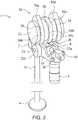
- Figures 1 and 2 illustrate schematically a valve train assembly 1 comprising a rocker arm 2 according to the first example.
- the rocker arm 2 may be any rocker arm comprising a plurality of bodies that move relative to one another, and which are latched together to provide one mode of operation (a latched valve-lift mode) and are unlatched, and hence can move with respect to each other, to provide a second mode of operation (an un-latched valve-lift mode).
- a valve train assembly 1 comprises a rocker arm 2, an engine valve 4 for an internal combustion engine cylinder (not shown) and a lash adjustor 6.
- the rocker arm 2 comprises an inner body or arm 8 and an outer body or arm 10.
- the inner body 8 is pivotally mounted on a shaft 12 which serves to link the inner body 8 and outer body 10 together.
- the shaft 12 is received through apertures 70a and 70b in side walls 60 and 62 of the outer body 10, and through apertures 46a and 46b in the inner body 8.
- a base 64a connects the side walls 60, 62 of the outer body 60.
- a first end 14 of the outer body 10 engages the stem 16 of the valve 4 and at a second end 20 the outer body 10 is mounted for pivotal movement on the lash adjustor 6 which is supported in an engine block (not shown).
- the lash adjuster 6 which may for example be a hydraulic lash adjuster, is used to accommodate slack between components in the valve train assembly 1. Lash adjusters are well known per se and so the lash adjuster 6 will not be described in detail.
- the rocker arm 2 is provided with a pair of main lift rollers 22a and 22b rotatably mounted on an axle 24 carried by the outer body 10.
- One of the main lift rollers 22a is located one side of the outer body 10 and the other of the main lift rollers 22b is located the other side of the outer body 10.
- the rocker arm 2 is further provided with a secondary lift roller 26, located within the inner body 8 and rotatably mounted on an axle (not visible in Figures 1 and 2 ) carried by the inner body 8.
- a three lobed camshaft 30 comprises a rotatable camshaft 32 mounted on which are first 34 and second 36 main lift cams and a secondary lift cam 38.
- the secondary lift cam 38 is positioned between the two main lift cams 34 and 36.
- the first main lift cam 34 is for engaging the first main lift roller 22a
- the second main lift cam 36 is for engaging the second main lift roller 22b
- the secondary lift cam 38 is for engaging the secondary lift roller 26.
- the first main lift cam 34 comprises a lift profile (i.e. a lobe) 34a and a base circle 34b
- second main lift cam 36 comprises a lift profile 36a and a base circle 36b
- the secondary lift cam 38 comprises a lift profile 38a and a base circle 38b.
- the lift profiles 34a and 36a are substantially of the same dimensions as each other and are angularly aligned.
- the lift profile 38a is smaller than the lift profiles 34a (both in terms of the height of its peak and in terms of the length of its base) and is angularly offset from them.
- the rocker arm 2 is switchable between a dual lift mode which provides two operations of the valve 4 (a valve operation is an opening and corresponding closing of the valve) per engine cycle (e.g. full rotation of the cam shaft 32) and a single lift mode which provides a single operation of the valve 4 per engine cycle.
- a valve operation is an opening and corresponding closing of the valve
- a single lift mode which provides a single operation of the valve 4 per engine cycle.
- the dual lift mode provides a higher main valve lift and a smaller secondary valve lift per engine cycle.
- the single lift mode provides just the main valve lift per engine cycle.
- the single lift mode is an example of a first valve-lift mode
- the dual lift mode is an example of a second valve-lift mode of the valve train assembly 1.
- the first main lift cam's lift profile 34a engages the first main lift roller 22a whilst, simultaneously, the second main lift cam's lift profile 36a engages the second main lift roller 22b and together they exert a force that causes the outer body 10 to pivot about the lash adjuster 6 to lift the valve stem 16 (i.e. move it downwards in the sense of the page) against the force of a valve spring (not shown) thus opening the valve 4.
- the valve spring begins to close the valve 4 (i.e.
- valve stem 16 is moved upwards in the sense of the page).
- first main lift cam's base circle 34b again engages the first main lift roller 22a and the second main lift cam's 36 lift profile engages the second main lift roller 22b the valve is fully closed and the main valve lift event is complete.
- the secondary lift cam's lift profile 38a engages the secondary lift roller 26 exerting a force on the inner body 8 which force, as the inner body 8 and the outer body 10 are latched together, is transmitted to the outer body 10 causing the outer body 10 to pivot about the lash adjuster 6 to lift the valve stem 16 against the force of a valve spring (not shown) thus opening the valve 4 a second time during the engine cycle.
- a valve spring (not shown) begins to close the valve 4 again.
- the secondary lift cam's base circle 38b again engages the secondary lift roller 26 the valve 4 is fully closed and the second valve lift event for the current engine cycle is complete.
- the lift profile 38a is shallower and narrower than are the lift profiles 34a and 36a and so consequently the second valve lift event is lower and of a shorter duration than is the first valve lift event.
- the inner body 8 and the outer body 10 are not latched together by the latching arrangement 40 and hence in this mode, the inner body 8 is free to pivot with respect to the outer body 10 about the shaft 12.
- the outer body 10 pivots about the lash adjuster 6 and, in an identical way as in the dual lift mode, a main valve lift event occurs.
- the secondary lift cam's lift profile 38a engages the secondary lift roller 26 exerting a force on the inner body 8.
- This arrangement may be used to provide switchable Internal Exhaust Gas Recirculation (IEGR) control.
- IEGR Internal Exhaust Gas Recirculation
- the valve 4 is an exhaust valve for an engine cylinder
- the main valve lift acts as the main exhaust lift of an engine cycle
- the timing of the secondary valve lift may be arranged so that it occurs when an intake valve for that cylinder, controlled by a further rocker arm (not shown) mounted pivotally on a further lash adjuster (not shown) and which pivots in response to an intake cam (not shown) mounted on the cam shaft 32, is open.
- the simultaneous opening of the intake and exhaust valves in this way ensures that a certain amount of exhaust gas remains in the cylinder during combustion which, as is well known, reduces NOx emissions.
- this switchable IEGR control may also be provided if the valve 4 is an intake valve with the timing of the secondary valve lift arranged to occur when an exhaust valve for that cylinder is open during the exhaust part of an engine cycle.
- the secondary lift roller 26 is mounted on a hollow inner bushing/ axle 43 which is supported in the apertures 48a and 48b.
- the axle 24 extends through the inner bushing/axle 43 (and hence through the inner roller 26) and the diameter of the axle 24 is somewhat smaller than the inner diameter of the inner bushing/axle 43 to allow movement of the assembly of the inner body 8, axle 43 and inner roller 26 relative to the outer body 10.
- the main lift rollers 22a and 22b are therefore arranged along a common longitudinal axis and the secondary lift roller 26 is arranged along a longitudinal axis that is slightly offset from this. This arrangement of axles and rollers ensures that the rocker 2 arm is compact and facilitates manufacturing the first 10 and second bodies from stamped metal sheets.
- the latching arrangement 40 comprises the latch pin 80 and an actuation member 84.
- the actuation member 84 comprises a sheet bent along its width to form first 84a and second 84b rectangular portions which define a right angle.
- the first portion 84a defines a hole 84c.
- the actuation member 84 further comprises a pair of winged portions extending rearwardly from the second portion 84c each of which defines a respective one of a pair of apertures 86a, 86b for supporting a shaft 88 on which is mounted a roller 90.
- the actuation member 84 straddles the end wall 66 of the outer body 10 with the second portion 84c slidably supported on the end wall 66 with the first portion 84a positioned between the end wall 66 and the inner wall 68 of the outer body 10.
- the latch pin 80 defines an upward facing latch surface 92.
- the latch pin 80 extends through the holes 74a in the end wall 66 and the hole 84c in the actuation member 84 and its end 93 engages the wing portions of the actuation member 84.
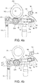
- Figures 4a and 4b illustrate the valve train assembly 1 when the rocker arm 2 is in the single lift mode (i.e. unlatched configuration).
- the actuation member 84 and latch pin 80 are positioned so that the latch surface 92 does not extend through the hole 74b and so does not engage the latch contact surface 54 of the inner body 8.
- the inner body 8 is free to pivot, with respect to the outer body 10, about the shaft 12 when the secondary roller 26 engages the lift profile 38a and hence there is no additional valve event. It will be appreciated that the amount of movement available to the inner body 8 relative to the outer body 10 (i.e.
- the amount of lost motion absorbed by the inner body 8) is defined by the size difference between the diameter of the axle 24 and the inner diameter of the inner bushing/axle 43.
- the torsional spring 67 which is installed over the top of the valve stem 16 and is located inside the inner body 10 by the shaft 12, acts as a lost motion spring that returns the inner body 8 to its starting position with respect to the outer body 10 after it has pivoted.
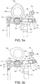
- Figures 5a and 5b illustrate the valve train assembly 1 when the rocker arm 2 is in the dual lift mode (i.e. a latched configuration).
- the actuation member 84 and latch pin 80 are moved forward (i.e. to the left in the sense of Figures 5a and 5b ) relative to their positions in the unlatched configuration so that the latch surface 92 does extend through the hole 74b so as to engage the latch contact surface 54 of the inner body 8.
- the inner body 8 and the outer I 10 act as a solid body so that when the when the secondary roller 26 engages the lift profile 38a there is an additional valve event.
- An actuator 94 is provided to move the latching arrangement 40 between the un-latched and latched positions.
- the actuator comprises an actuator shaft 96 carrying a biasing means 98, which in this example comprises a flexible strip, for example a leaf spring.
- a biasing means 98 which in this example comprises a flexible strip, for example a leaf spring.
- the leaf spring 98 does not engage the latching arrangement 40.
- the shaft 96 is rotated a certain amount (for example 12 degrees) causing the leaf spring 98 to engage the roller 90 and to push the latching arrangement 40 into the latched position.
- a spring 85 mounted over the latch pin 80 and supported between an outer face of the end wall 66 and the winged members of the member 84 is biased to cause the latching arrangement 40 to return to its unlatched position when the actuator shaft 96 is rotated back to its unlatched position and the leaf spring 98 disengages the roller 90.
- the inner bushing axle 43 stops on the axle 24 which ensures that the orientation of the various components is such that the latch pin 80 is free to move in and out of the latched and unlatched positions.
- Figure 4a illustrates the valve train assembly 1 when the rocker arm 2 is in the single lift mode (i.e. the un-latched configuration) at a point in an engine cycle when the main lift rollers 22a and 22b are engaging the respective base circles 34b and 36b of the first main lift cam 34 and the second main lift cam 36. At this point in the engine cycle, the valve 4 is closed.
- Figure 4b illustrates the valve train assembly 1 when the rocker arm 2 is in the single lift mode at another point in an engine cycle when the main lift rollers 22a and 22b are engaging the respective peaks of the lift profiles 34a and 36a of the first main lift cam 34 and the second main lift cam 36. At this point in the engine cycle the valve 4 is fully open and the 'maximum lift' of the main valve event is indicated as M.
- Figure 5a illustrates the valve train assembly 1 when the rocker arm 2 is in the dual lift mode (i.e. the latched configuration) at a point in an engine cycle when the main lift rollers 22a and 22b are engaging the respective base circles 34b and 36b of the first main lift cam 34 and the secondary lift roller 26 is engaging the base circle 38b of the secondary lift cam 38.
- the valve 4 is closed.
- Figure 5b illustrates the valve train assembly 1 when the rocker arm 2 is in the single lift mode at another point in an engine cycle when the main lift rollers 22a and 22b are engaging the respective base circles 34b and 36b of the first main lift cam 34 and the second main lift cam 36 and the secondary lift roller 26 is engaging the peak of the lift profile 38a of the secondary lift cam 38.
- the valve 4 is fully open during the additional valve event and the 'maximum lift' of the secondary valve event is indicated as M'.
- Figure 6 illustrates a graph in which the Y axis indicates valve lift and the X axis indicates rotation of the cam shaft.
- the curve 100 represents the main lift of the exhaust valve during an engine cycle and the curve represents 101 the additional lift of the exhaust valve during the subsequent engine cycle.
- the curve 102 represents the lift of intake valve (not shown in the figures), during the subsequent engine cycle, operated by an intake rocker arm (again not shown in the Figures) in response to an intake cam (not shown in the Figures) mounted on the cam shaft. It can be seen that the cams are arranged so that in any given engine cycle, the additional smaller opening of the exhaust valve occurs when the intake valve is open to thereby provide a degree of internal exhaust gas recirculation.
- valve 4 is an intake valve rather than an exhaust valve (making the rocker arm 2 an intake rocker arm) and an exhaust rocker arm operates an exhaust valve in response to an exhaust cam mounted on the cam shaft.
- the cams are arranged so that in any given engine cycle, the additional smaller opening of the intake valve occurs when the exhaust valve is open to thereby provide a degree of internal exhaust gas recirculation.
- FIGs 7 to 9 illustrate a valve train assembly 1', comprising an actuation transmission apparatus 200, according to a second example.
- FIGs 7 to 9 illustrate a valve train assembly 1', comprising an actuation transmission apparatus 200, according to a second example.
- Features described with reference to Figure 7 to 9 that are the same or similar to those described with reference to Figures 1 to 6 are given like reference signs but followed by a prime (').
- the actuation transmission apparatus 200 actuates a component (not visible in Figures 7 to 9 ) of a switchable valve train device 2' of the valve train assembly 1' of an internal combustion engine (not shown).
- the switchable valve train device 2' is a switchable rocker arm 2'.
- the switchable rocker arm 2' may be the same or similar to the switchable rocker arm 2 described above with reference to Figures 1 to 6 .
- the component (not visible) of the switchable valve train device 2' that is actuated is a moveable latching arrangement (not visible in Figures 7 to 9 but see e.g. latching arrangement 40 described above with reference to Figures 1 to 6 ) of the rocker arm 2'.
- the latching arrangement (not visible) comprises a moveable latch pin (not visible in Figures 7 to 9 but see e.g. latch pin 80 described above with reference to Figures 1 to 6 ) for latching an inner body 8' and an outer body 10' of the rocker arm 2' together.
- the actuation transmission apparatus 200 transmits an actuation signal (force) from an actuation source 3 to the latch pin (not visible) of the switchable rocker arm 2'.
- the inner body 8' and an outer body 10' may be latched together by the moveable latch pin (not visible) to provide one mode of operation (e.g. a first valve-lift mode, e.g. a dual lift mode as described above) and unlatched, and hence can pivot with respect to each other, to provide a second mode of operation (e.g. a second valve-lift mode, e.g. a single lift mode as described above).
- a first valve-lift mode e.g. a dual lift mode as described above
- a second mode of operation e.g. a second valve-lift mode, e.g. a single lift mode as described above.
- the outer body 10' and the inner body 8' are pivotably connected together at a pivot axis 12'.
- a first end 14' of the outer body 10' contacts a valve stem (not shown in Figures 7 to 9 ) of a valve (not shown in Figures 7 to 9 ) and a second end (not visible in Figures 7 to 9 ) of the outer body 10' contacts a hydraulic lash adjuster (HLA) (not shown in Figures 7 to 9 ).
- HLA hydraulic lash adjuster
- the outer body 10' is arranged to move or pivot about the HLA (not shown in Figures 7 to 9 ).
- the rocker arm 2' further comprises at the second end (not visible in Figures 7 to 9 ) of the outer body 10' the latching arrangement (not visible in Figures 7 to 9 , but see e.g. latching arrangement 40 of Figures 1 to 6 ) comprising the latch pin (not visible in Figures 7 to 9 , but see e.g.
- latch pin 80 of Figures 1 to 6 that can be actuated between a first position in which the outer body 10' and the inner body 8' are un-latched and hence can pivot with respect to each other about the pivot axis 12' and a latched position in which the outer body 10' and the inner body 8' are latched together and hence can move or pivot about the HLA (not shown in Figures 7 to 9 ) as a single body.
- the latching arrangement (not visible) comprises a biasing element (not visible in Figures 7 to 9 but see e.g. spring 85 of the latching arrangement 40 of the rocker arm 2 as described above with reference to Figures 1 to 6 ) that biases the latch pin (not visible) to the unlatched position. Therefore, in a default state, i.e. when substantially no actuation force is applied to the latch pin (not visible), the latch pin (not visible) is urged by the biasing element (not visible) to its default, unlatched, position.
- a biasing element not visible in Figures 7 to 9 but see e.g. spring 85 of the latching arrangement 40 of the rocker arm 2 as described above with reference to Figures 1 to 6 .
- the inner body 8' is provided with an inner body cam follower 26', for example, a roller follower 26' for following a secondary lift cam (not shown in Figures 7 to 9 ).
- the outer body 10' is provided with a pair of roller followers 22a', 22b', for example, main lift rollers 22a', 22b' arranged either side of the roller follower 26' for following a pair of main lift cams (not shown in Figures 7 to 9 ).
- the rocker arm 2' further comprises a return spring arrangement 67' for returning the inner body 8' to its rest position after it is has pivoted with respect to the outer body 10'.
- the rocker arm 2' When the latch pin (not visible) of the rocker arm 2' is in the latched position, the rocker arm 2' provides a first function, for example, a dual lift mode as described above with reference to Figures 1 to 6 . When the latch pin (not visible) of the rocker arm 2' is in the unlatched position, the rocker arm 2' provides a second function, for example, a single lift mode as described above with reference to Figures 1 to 6 .
- rocker arm 2' may be any rocker arm comprising a plurality of bodies that move relative to one another, and which are latched together to provide one mode of operation (valve-lift mode) and are unlatched, and hence can move with respect to each other, to provide a second mode of operation (valve-lift mode).
- rocker arm 2' may configured for internal Exhaust Gas Recirculation (iEGR), Cylinder Deactivation (CDA), Early Exhaust Valve Opening (EEVO), or the like applications.
- the actuation transmission apparatus 200 comprises a transmission lever 208 for contacting with the actuation source 3, a shaft 210 that is mechanically coupled to the transmission lever 208 such that the shaft 210 is rotatable by the actuation source 3, a shaft support body 224 arranged to support the shaft 210, a contacting element 212 for contacting the latching arrangement (not visible) of the rocker arm 2', and a biasing means 214 (also referred to herein as a compliance spring 214) to bias the contacting element 212 rotationally with respect to the shaft 210.
- the actuation transmission apparatus 200 also comprises a preload element 226, attached to the shaft 210, for transferring a torque to the biasing means 214 from the shaft 210.
- the pre-load element comprises a radial protrusion 226a for contacting and applying the torque to the biasing means 214.
- the actuation transmission apparatus 200 is arranged to actuate the latch pin (not visible) of the rocker arm 2' by moving the latch pin (not visible) from the unlatched to the latched position.
- the biasing means 214 becomes biased by the shaft 210 when the actuation source 3 rotates the shaft 210 (via the lever 208) when the actuation source 3 attempts to actuate the latch pin (not visible) of the rocker arm 2', via the contacting element 212, at a time when the latch pin (not visible) cannot be actuated, for example, at a time when the relative orientation of the outer body 10' and the inner body 8' prevents the latch pin (not visible) from being able to move.
- the biasing means 214 so energised can then cause the contacting element 212 to actuate the latch pin (not visible) of the rocker arm 2' when the latch pin (not visible) next becomes actuatable.
- the actuation source 3 (also referred to herein as an actuator 3) comprises a drive rod 216 that can be controlled to rotate about its axis.
- the rod 216 may be caused to rotate when switching of a mode of operation of the switchable rocker arm is required.
- the rod 216 may be limited in its extent of rotation, for example only between certain angles.
- the actuation source 3 comprises a drive means 3a that is controllable to cause the rod 216 to rotate.
- the rod 216 may be controlled to rotate using any suitable drive means 3a, such as electrical, hydraulic, and/or pneumatic means.
- the rod 216 has a coupler 218 extending radially therefrom for contacting with the lever 208 and transforming, via the lever 208, the rotational movement of the drive rod 216 about the axis of the drive rod 216 into rotational movement of the shaft 210 about the axis of the shaft 210.
- the axis of the shaft 210 is perpendicular to the axis of the rod 216.
- the coupler 218 is L shaped and has a mouth portion 220 at its distal end 218a for receiving therein a distal end 208a of the lever 208.
- the lever 208 is mechanically coupled to the shaft 210 and extends radially therefrom.
- the lever 208 is generally elongate.
- the lever 208 may comprise one or more mechanical stopping features 222 to restrict the rotation of the lever 208 about the axis of the shaft 210 (and hence restrict the rotation of the shaft 210) to within a certain range of angles (i.e. to restrict an extent of rotation of the lever 208 about the axis of the shaft 210).
- the shaft support body 224 (through which the shaft 210 extends) may comprise one or more protrusions 227 against which the mechanical stopping feature(s) 222 of the lever may abut, thereby to restrict the rotation of the lever 208 about the axis of the shaft 210 (and hence restrict the rotation of the shaft 210) to within a certain range of angles.
- the lever 208 comprises two mechanical stopping features 222.
- Each mechanical stopping feature 222 is a protrusion 222 from the lever 208, located towards the end of the lever 208 connected to the shaft 210.
- Each protrusion 222 is disposed in a corresponding recess 224a, defined between two protrusions 227 of the shaft support body 224.
- the shaft 210 is received in the recess 224a.
- the extent of rotation of the lever 208 about the axis of the shaft 210 (and hence the extent of the rotation of the shaft 210 itself) is restricted in one direction by the mechanical stopping feature 222 abutting one of the two protrusions 227 of the shaft support body 224, and in the other direction by the mechanical stopping feature 222 abutting the other of the two protrusions 227 of the shaft support body 224.
- the lever 208 (and hence the shaft 210) is thereby prevented from over-rotating, hence avoiding damage to components on the valve train assembly.
- a return spring (not shown), or any suitable biasing means (not shown), may be installed on the shaft 210 and shaft support body 224 to define the positions (initial and final) of the shaft 210.
- the return spring (not shown) may be arranged to bias the shaft 210 rotationally with respect to the support body. This may ensure a default orientation of the shaft 210 (and hence contacting element 212) is maintained when actuation of the rocker arm 2 is not required.
- the shaft 210 is mechanically coupled to the contacting element 212 via the biasing means 214.
- the biasing means (compliance spring) 214 may be for example a coil spring 214 wrapped around the shaft 210 (or a component 226 thereof).
- the compliance spring 214 is a coil spring 214 wrapped around the pre-load element 226 which itself is wrapped around the shaft 210.
- a first end 214a of the compliance spring 214 contacts the radial protrusion 226a of the pre-load element 226, and a second end 214b of the compliance spring 214 contacts the contacting element 212 thereby to bias the contacting element 212 rotationally with respect to the shaft 210, towards the rocker arm 2.
- the shaft 210 When the shaft 210 rotates, the radial protrusion 226a of the pre-load element 226 applies a torque force to the compliance spring 214, thereby energising the compliance spring 214. Therefore, the shaft 210 may rotate with respect to contacting element 212, but in doing so the biasing means (compliance spring) 214 will become energised and will urge the contacting element 212 to follow the rotation of the shaft 210.
- the contacting element 212 is generally elongate and extends radially from the shaft 210.
- the contacting element 212 has at a first end 212a, a contacting feature 228 that contacts with the latching arrangement (not visible in Figures 7 to 9 ) of the rocker arm 2'.
- the contacting feature 228 may be or comprise a flexible strip 228 and/or may be hook shaped.
- the contacting feature 228 defines a curved surface 228a for contacting the latching arrangement (not visible) so as to reduce wear of the contact surface and to enable the contacting element 212 to apply a force on the latch pin (not visible) towards the outer body 10' of the rocker arm 2' regardless of rotation of the outer body 10' about the hydraulic lash adjuster (not shown) during the engine cycle.
- the actuation transmission apparatus 200 in response to rotation of the rod 216 of the actuator 3, actuates (e.g. moves) the latch pin (not visible in Figures 7 to 9 ) against the biasing element (not visible) to latch the inner body 8' and the outer body 10' of the rocker arm 2' together.
- the latch pin (not visible) of the rocker arm 2' is actuated when the latch pin (not visible) is moved, by the contacting element 212, from an unlatched position in which the inner body 8' and the outer body 10' are unlatched so that the inner body 8' and the outer body 10' are moveable relative to one another, to a latched position in which the inner body 8' and the outer body 10' are latched together.
- the actuation transmission apparatus 200 applies substantially no force on the latch pin (not visible) and the latch pin is de-actuated (e.g. moved) under the force of the biasing element of the latching arrangement (not visible) to unlatch the inner body 8' and the outer body 10'.
- the rod 216 rotates anticlockwise (when looking along the rod 216 towards the drive means 3a) which causes, via the lever 208, the shaft 210 to rotate anticlockwise (when looking along the shaft 210 towards the contacting element 212 from the lever 208), which causes the contacting element 212 to be urged, via the biasing means 214, into rotation anticlockwise (when looking along the shaft 210 towards the contacting element 212 from the lever 208) to contact the latching arrangement (not visible in Figures 7 to 9 ) of the rocker arm 2'.
- the rotation of the shaft 210 anticlockwise causes the radial protrusion 226a of the pre-load element 226 to exert a torque force on the compliance spring 214, which in turn causes the contacting element 212 to be urged into rotation anticlockwise (when looking along the shaft 210 towards the contacting element 212 from the lever 208, in the sense of Figure 7 ) to contact the latching arrangement (not visible) of the rocker arm 2', thereby to urge the latch pin (not visible) towards and into the rocker arm 2'.
- the contacting element 212 exerts a force on the latch pin (not visible) in a direction towards the inner body 8 and the outer body 10.
- the rocker arm 2' may therefore be immediately switched from, say, a second lift mode (e.g. single lift mode) to a first lift mode (e.g. dual lift mode).
- a second lift mode e.g. single lift mode
- a first lift mode e.g. dual lift mode
- the latch pin (not visible in Figures 7 to 9 ) may not be free to move (i.e. it may be blocked).
- the actuation of the latch pin may not be possible immediately due to an engine condition.
- a lift profile (not shown) of a secondary lift cam (not shown) may be engaged with a secondary lift roller follower 26' of the inner body 8' of the rocker arm 2'.
- the inner body 8' will be rotated with respect to the outer body 10', hence blocking the path of the latch pin (not visible) from moving from the unlatched position to the latched position.
- the contacting element 212 will be restricted (blocked) from rotating with the shaft 210 when the shaft 210 is caused to rotate, and instead the rotation of the shaft 210 will cause the biasing means (compliance spring) 214 to be energised (i.e. to elastically deform from its natural configuration). That is, the spring 214 absorbs the actuation signal in case the switchable device 2' cannot be switched directly.
- the latch pin not visible
- the energy stored in the biasing of the spring 214 will cause the contacting element 212 to rotate anticlockwise about the shaft 210 (when looking along the shaft 210 towards the contacting element 212 from the lever 208), and hence cause the latch pin (not visible) to actuate, hence latching the inner body 8' and the outer body 10' together (and hence switching the rocker arm 2' from, say, a second lift mode (e.g. single lift mode) to a first lift mode (e.g. dual lift mode) as described above).
- a second lift mode e.g. single lift mode
- a first lift mode e.g. dual lift mode
- the biasing means (compliance spring) 214 will return to its natural, non-deformed state, and transmit the actuation signal/energy to the latch pin (not visible). That is as soon as the engine condition allows for the switchable valve train device (e.g. rocker arm 2') to be switched, the spring 214 will expand again and transmit the signal to the switchable valve train device (e.g. rocker arm) 2.
- the latch pin (not visible) may be free to be actuated as soon as an engine cycle occurs where the inner body 8' is not rotated with respect to the outer body 10', and hence a gap (not visible) into which the latch pin may move is free.
- the latch pin (not visible in Figures 7 to 9 ) may be actuated as soon as it is physically possible to do so, i.e. as soon as the rocker arm 2' is not in a state which blocks actuation of the latch pin (not visible).
- the switching of the rocker arm 2' from, say, a second lift mode (e.g. single lift mode) to a first lift mode (e.g. dual lift mode) as described above is in effect delayed with respect to the actuation signal/force coming from the actuator 3 to the earliest possible time that such switching is physically possible.
- the drive rod 216 of the actuator 3 may return to its original position (e.g. when deactuation of the latch pin (not visible) is required), and hence the contacting element 212 ceases to apply a force on the latching arrangement (not visible), and hence the latch pin (not visible) may return to its default, unlatched position under force of the biasing element (not visible in Figures 7 to 9 ) that biases the latch pin (not visible) to its default, unlatched position.
- the above solution allows easy packaging and installation of the actuation transmission apparatus 200 on an engine.
- the transmission apparatus 200 allows for the actuation to happen as soon as possible.
- the solution allows actuation to be effected by the actuation transmission apparatus 200 by a limited rotation or translation of the actuation system 200, reducing the impact to the engine's layout and the number and complexity of the actuation system components.
- the installation of the actuation transmission apparatus 200 on the engine is simple since a limited number of installation points are required on the engine and it can be also installed inside plastic covers.
- the storing of the signal/energy/force by the biasing means 214 can be achieved by any suitable elastic element, e.g. any suitable biasing means.
- the actuation transmission apparatus 200 may actuate a different component of a different switchable valve train device, not necessarily a latch pin of rocker arm 2'.
- the actuation transmission apparatus 200 may transmit the activation signal/force from an actuator 3 rotation, or a linear actuation force, form one point to another.
- the actuation transmission apparatus 200 may comprise a plurality of such contacting elements 212 for contacting a respective plurality of components of a respective plurality of switchable valve train devices 2' (e.g. a respective plurality of latching arrangements of a respective plurality of rocker arms 2').
- the shaft 210 may be common to each of those plurality of contacting elements 212, so that multiple devices (e.g. rocker arms 2) may be switched at the same time.
- the actuation transmission apparatus 200 may comprise a shaft 210 rotatable by an actuation source 3, a plurality of contacting elements 212 each mechanically coupled to the shaft 210, each for contacting a respective one of a plurality of components of a respective plurality of switchable valve train devices 2', and a respective plurality of biasing means 214 each to bias a respective one of the plurality of contacting elements 212 rotationally with respect to the shaft 210.
- the biasing means 214 becomes biased by the shaft 210 when the actuation source 3 rotates the shaft 210 when the actuation source 3 attempts to actuate the plurality of components of the switchable valve train devices 2', via the respective contacting elements 212, when the respective component is not able to be actuated, whereby the biasing means 214 causes the respective contacting element 212 to actuate the respective component of the respective switchable valve train device 2' when the respective component becomes actuatable again.
- the actuation transmission apparatus 200 may allow for the actuation of components of various switchable valve train devices (e.g. rocker arm 2') to happen as soon as possible.
- the actuation transmission apparatus 200 may therefore capture and store the activation signal or energy and transmit it to the component as soon as the actuation can happen.
- the storing of the signal / energy can be achieved by the means of any elastic element 214.
- the mechanical connection between the actuator 3 and the shaft 210 may be for example electrical, hydraulic, and/or pneumatic. This mechanical connection may be the last operation when assembling the engine, hence allowing for convenient assembly.
Landscapes
- Engineering & Computer Science (AREA)
- Mechanical Engineering (AREA)
- General Engineering & Computer Science (AREA)
- Chemical & Material Sciences (AREA)
- Combustion & Propulsion (AREA)
- Valve Device For Special Equipments (AREA)
Description
- The present invention relates to actuation, and more specifically actuation of components of switchable engine or valve train devices of an internal combustion engine.
- Internal combustion engines may comprise switchable engine or valve train devices. For example, valve train assemblies may comprise a switchable rocker arm to provide for control of valve actuation by alternating between at least two or more modes of operation (e.g. valve-lift modes). Such rocker arms typically involve multiple bodies, such as an inner arm and an outer arm. These bodies are latched together to provide one mode of operation (e.g. a first valve-lift mode) and are unlatched, and hence can pivot with respect to each other, to provide a second mode of operation (e.g. a second valve-lift mode). Typically, a moveable latch pin is used and actuated and de-actuated to switch between the two modes of operation.
-
WO 2013/156610 A1 [EATON SRL] discloses such a dual lift rocker arm with a moveable latch pin. The default position of the latch pin is unlatched, and it is retained in this position using biasing means. When required, the latch pin is actuated to the latched position using an external actuation mechanism based on a leaf spring. When actuation is required, the leaf spring is controlled to rotate a certain amount so as to engage with a roller of the latch pin, and hence push the latch pin into the latched position. - The transmission of an actuation force to a component of a switchable valve train or engine device such as a switchable rocker arm can be difficult due to packaging constraints and functional requirements. Also, in some cases, actuation may not be possible immediately due to an engine condition.
- It is desirable to provide an actuation transmission system that addresses these problems.
-
US 2005/092273 A1 discloses a deactivating valve control system for an internal combustion engine and, for each deactivating intake poppet valve, there is provided a deactivating lash compensation device. Each of the devices includes a latch member biased toward an unlatched condition by a spring member, including a vertically-extending spring portion. -
GB 2 526 554 AUS 5 653 198 A discloses a finger follower rocker arm system for an internal combustion engine includes a body having a first end engageable with a valve stem of the internal combustion engine and a second end engageable with a pivot fulcrum of the internal combustion engine, an arm mounted on the body between the first end and second end engageable with a cam lobe of the internal combustion engine. - According to a first aspect of the present invention, there is provided an actuation transmission apparatus for actuating a component of a switchable valve train device of an internal combustion engine, the apparatus comprising: a shaft rotatable by an actuation source; a contacting element for contacting the component of the switchable valve train device; and a biasing means to bias the contacting element rotationally with respect to the shaft; wherein, in use, the biasing means becomes biased by the shaft when the actuation source rotates the shaft when the actuation source attempts to actuate the component of the switchable valve train device via the contacting element, when the component of the switchable valve train device is not able to be actuated, whereby the biasing means causes the contacting element to actuate the component of the switchable valve train device when the component of the switchable valve train device becomes actuatable again.
- The biasing means may be a coil spring arranged around the shaft.
- The actuation transmission apparatus may comprise a pre-load element for transferring a torque from the shaft to the coil spring.
- A first end of the coil spring may contact a protrusion of the pre-load element, and a second end of the coil spring may contact the contacting element (212), thereby to bias the contacting element rotationally with respect to the shaft.
- The contacting element may extend radially from the shaft.
- The contacting element may define a curved surface for contacting the component of the switchable valve train component device.
- The actuation transmission apparatus may comprise a lever mechanically coupled to the shaft and extending radially therefrom, the lever being rotatable, by the actuation source, about an axis of the shaft, thereby allowing the shaft to be rotatable by the actuation source.
- The lever may comprise one or more mechanical stopping features to restrict an extent of rotation of the lever about the axis of the shaft.
- The actuation transmission apparatus may comprise a support body for supporting the shaft, wherein the support body comprises one or more protrusions for abutting against the one or more mechanical stopping features of the lever thereby to restrict the extent of rotation of the lever about the axis of the shaft.
- The actuation transmission apparatus may comprise a second biasing means arranged to bias the shaft rotationally with respect to the support body.
- The actuation transmission apparatus may comprise a plurality of said contacting elements for contacting a respective plurality of said components of said switchable valve train devices, a respective plurality of said biasing means to bias the respective contacting elements rotationally with respect to the shaft, and the shaft may be common to each of the plurality of contacting elements.
- According to a second aspect of the present invention, there is provided a valve train assembly of an internal combustion engine, the valve train assembly comprising:
the actuation transmission apparatus according to the first aspect; a said actuation source; and a said switchable valve train device comprising a said component. - In use, when the actuation source rotates the shaft when the actuation source attempts to actuate the component of the switchable valve train device, via the contacting element, when the component of the switchable valve train device is actuatable, the contacting element may actuate the component of the switchable valve train device immediately.
- The switchable valve train device may be a switchable rocker arm.
- The switchable rocker arm may comprise a first body and a second body, and the component of the switchable rocker arm may be a latching arrangement comprising a moveable latch pin for latching the first body and the second body together.
- Actuating the latching arrangement of the switchable rocker arm may comprise moving the latch pin from an unlatched position in which the first body and the second body are unlatched so that the first body and the second body are moveable relative to one another, to a latched position in which the first body and the second body are latched together.
- The switchable rocker arm may comprise a biasing element to bias the latch pin towards the unlatched position. When the actuation source rotates the shaft when the actuation source attempts to actuate the latch pin of the switchable rocker arm, the contacting element may be caused to exert a force on the latching arrangement in a direction towards the first body and the second body.
- The switchable rocker arm may be arranged such that, when the first body and the second body are unlatched, the switchable rocker arm provides a first mode of operation, and when the first body and the second body are latched together by the latch pin, the switchable rocker arm provides a second mode of operation.
- The second mode of operation may be internal exhaust gas recirculation.
- The actuation source may comprise a drive means controllable to rotate a drive rod about an axis of rotation of the drive rod.
- The axis of rotation of the drive rod may be substantially perpendicular to the axis of rotation of the shaft.
- The actuation source may comprise a coupler extending radially from the drive rod and for contacting the lever and arranged to transform rotational movement of the drive rod about the axis of the drive rod to rotational movement of the shaft about the axis of the shaft.
- According to a third aspect of the present invention, there is provided a method of actuating a component of a switchable valve train device of an internal combustion engine, the method comprising: rotating a shaft so as to bias, when the component of the switchable valve train device is not able to be actuated, a biasing means that biases a contacting element rotationally with respect to the shaft, the contacting element being for contacting the component of the switchable valve train device, whereby the biasing means causes the contacting element to actuate the component of the switchable valve train device when the component of the switchable valve train device becomes actuatable again.
- Further features and advantages of the invention will become apparent from the following description of preferred embodiments of the invention, given by way of example only, which is made with reference to the accompanying drawings. In the following, like parts are given like reference numerals.
-
-
Figure 1 illustrates a schematic perspective view of an example valve train assembly including an example rocker arm, according to a first example; -
Figure 2 illustrates another perspective view of the example valve train assembly; -
Figure 3 is an exploded view of the example rocker arm; -
Figures 4a and 4b schematically illustrate the example valve train assembly at two different points in engine cycle when the inner and outer bodies are latched; -
Figures 5a and 5b schematically illustrate the example valve train assembly at two different points in engine cycle when the inner and outer bodies are un-latched; -
Figure 6 illustrates a graph showing valve lift against cam shaft rotation; -
Figure 7 illustrates a schematic perspective view of a portion of a valve train assembly including a rocker arm and an example actuation transmission apparatus, according to a second example; -
Figure 8 schematically illustrates a perspective view of a portion of the exemplary actuation transmission apparatus; and -
Figure 9 schematically illustrates a cross section of a portion of the exemplary actuation transmission apparatus. - To facilitate understanding of the present invention, first a
valve train assembly 1 according to a first example is described with reference toFigures 1 to 6 . Following this, a valve train assembly 1', comprising anactuation transmission apparatus 200, according to a second example is described with reference toFigures 7 to 9 . -
Figures 1 and2 illustrate schematically avalve train assembly 1 comprising arocker arm 2 according to the first example. Although theexample rocker arm 2 is referred to in the below, it will be appreciated that therocker arm 2 may be any rocker arm comprising a plurality of bodies that move relative to one another, and which are latched together to provide one mode of operation (a latched valve-lift mode) and are unlatched, and hence can move with respect to each other, to provide a second mode of operation (an un-latched valve-lift mode). - Referring again to the example of
Figures 1 and2 , avalve train assembly 1 comprises arocker arm 2, anengine valve 4 for an internal combustion engine cylinder (not shown) and alash adjustor 6. Therocker arm 2 comprises an inner body orarm 8 and an outer body orarm 10. Theinner body 8 is pivotally mounted on ashaft 12 which serves to link theinner body 8 andouter body 10 together. Theshaft 12 is received throughapertures side walls outer body 10, and throughapertures inner body 8. Abase 64a connects theside walls outer body 60. Afirst end 14 of theouter body 10 engages thestem 16 of thevalve 4 and at a second end 20 theouter body 10 is mounted for pivotal movement on thelash adjustor 6 which is supported in an engine block (not shown). Thelash adjuster 6, which may for example be a hydraulic lash adjuster, is used to accommodate slack between components in thevalve train assembly 1. Lash adjusters are well known per se and so thelash adjuster 6 will not be described in detail. - The
rocker arm 2 is provided with a pair ofmain lift rollers axle 24 carried by theouter body 10. One of themain lift rollers 22a is located one side of theouter body 10 and the other of themain lift rollers 22b is located the other side of theouter body 10. Therocker arm 2 is further provided with asecondary lift roller 26, located within theinner body 8 and rotatably mounted on an axle (not visible inFigures 1 and2 ) carried by theinner body 8. - A three
lobed camshaft 30 comprises arotatable camshaft 32 mounted on which are first 34 and second 36 main lift cams and asecondary lift cam 38. Thesecondary lift cam 38 is positioned between the twomain lift cams main lift cam 34 is for engaging the firstmain lift roller 22a, the secondmain lift cam 36 is for engaging the secondmain lift roller 22b and thesecondary lift cam 38 is for engaging thesecondary lift roller 26. The firstmain lift cam 34 comprises a lift profile (i.e. a lobe) 34a and abase circle 34b, secondmain lift cam 36 comprises alift profile 36a and abase circle 36b and thesecondary lift cam 38 comprises alift profile 38a and abase circle 38b. The lift profiles 34a and 36a are substantially of the same dimensions as each other and are angularly aligned. Thelift profile 38a is smaller than thelift profiles 34a (both in terms of the height of its peak and in terms of the length of its base) and is angularly offset from them. - The
rocker arm 2 is switchable between a dual lift mode which provides two operations of the valve 4 (a valve operation is an opening and corresponding closing of the valve) per engine cycle (e.g. full rotation of the cam shaft 32) and a single lift mode which provides a single operation of thevalve 4 per engine cycle.In the dual lift mode, theinner body 8 and theouter body 10 are latched together by a latching arrangement 40 (seeFigure 2 ) and hence act as a single solid body.With this particular arrangement, the dual lift mode provides a higher main valve lift and a smaller secondary valve lift per engine cycle. The single lift mode provides just the main valve lift per engine cycle. The single lift mode is an example of a first valve-lift mode, and the dual lift mode is an example of a second valve-lift mode of thevalve train assembly 1. - During engine operation in the dual lift mode, as the
cam shaft 32 rotates, the first main lift cam'slift profile 34a engages the firstmain lift roller 22a whilst, simultaneously, the second main lift cam'slift profile 36a engages the secondmain lift roller 22b and together they exert a force that causes theouter body 10 to pivot about thelash adjuster 6 to lift the valve stem 16 (i.e. move it downwards in the sense of the page) against the force of a valve spring (not shown) thus opening thevalve 4. As the peaks of thelift profiles main lift roller 22a and the secondmain lift roller 22b, the valve spring (not shown) begins to close the valve 4 (i.e. thevalve stem 16 is moved upwards in the sense of the page). When the first main lift cam'sbase circle 34b again engages the firstmain lift roller 22a and the second main lift cam's 36 lift profile engages the secondmain lift roller 22b the valve is fully closed and the main valve lift event is complete. - As the
camshaft 32 continues to rotate, then, the secondary lift cam'slift profile 38a engages thesecondary lift roller 26 exerting a force on theinner body 8 which force, as theinner body 8 and theouter body 10 are latched together, is transmitted to theouter body 10 causing theouter body 10 to pivot about thelash adjuster 6 to lift thevalve stem 16 against the force of a valve spring (not shown) thus opening the valve 4 a second time during the engine cycle. As the peak of thelift profile 38a passes out of engagement with thesecondary lift roller 26 the valve spring (not shown) begins to close thevalve 4 again. When the secondary lift cam'sbase circle 38b again engages thesecondary lift roller 26 thevalve 4 is fully closed and the second valve lift event for the current engine cycle is complete. - The
lift profile 38a is shallower and narrower than are thelift profiles - In the single lift mode, the
inner body 8 and theouter body 10 are not latched together by the latchingarrangement 40 and hence in this mode, theinner body 8 is free to pivot with respect to theouter body 10 about theshaft 12. During engine operation in the single lift mode, as thecam shaft 32 rotates, when the first main lift cam'slift profile 34a engages the firstmain lift roller 22a and the second main lift cam'slift profile 36a engages the secondmain lift roller 22b, theouter body 10 pivots about thelash adjuster 6 and, in an identical way as in the dual lift mode, a main valve lift event occurs. As thecamshaft 32 continues to rotate, then, the secondary lift cam'slift profile 38a engages thesecondary lift roller 26 exerting a force on theinner body 8. In the single lift mode, however, as theinner body 8 and theouter body 10 are not latched together, this force is not transmitted to theouter body 10 which hence does not pivot about thelash adjuster 6 and so there is no additional valve event during the engine cycle. Instead, as the secondary lift cam'slift profile 38a engages thesecondary lift roller 26, theinner body 8 pivots with respect to theinner body 10 about theshaft 12 accommodating the motion that otherwise would be transferred to theouter body 10. A torsional lost motion spring (not shown inFigures 1 and2 ) is provided to return theinner body 8 to its starting position relative to theouter body 10, once the peak of thelift profile 38a has passed out of engagement with thesecondary lift roller 26. - This arrangement may be used to provide switchable Internal Exhaust Gas Recirculation (IEGR) control. For example, if the
valve 4 is an exhaust valve for an engine cylinder, the main valve lift acts as the main exhaust lift of an engine cycle, and the timing of the secondary valve lift may be arranged so that it occurs when an intake valve for that cylinder, controlled by a further rocker arm (not shown) mounted pivotally on a further lash adjuster (not shown) and which pivots in response to an intake cam (not shown) mounted on thecam shaft 32, is open. The simultaneous opening of the intake and exhaust valves in this way ensures that a certain amount of exhaust gas remains in the cylinder during combustion which, as is well known, reduces NOx emissions. Switching to the single lift mode deactivates the IEGR function, which deactivation may be desirable under certain engine operating conditions. As will be appreciated by those skilled in the art, this switchable IEGR control may also be provided if thevalve 4 is an intake valve with the timing of the secondary valve lift arranged to occur when an exhaust valve for that cylinder is open during the exhaust part of an engine cycle. - As is best understood from
Figure 3 , thesecondary lift roller 26 is mounted on a hollow inner bushing/axle 43 which is supported in theapertures axle 24 extends through the inner bushing/axle 43 (and hence through the inner roller 26) and the diameter of theaxle 24 is somewhat smaller than the inner diameter of the inner bushing/axle 43 to allow movement of the assembly of theinner body 8,axle 43 andinner roller 26 relative to theouter body 10. Themain lift rollers secondary lift roller 26 is arranged along a longitudinal axis that is slightly offset from this. This arrangement of axles and rollers ensures that therocker 2 arm is compact and facilitates manufacturing the first 10 and second bodies from stamped metal sheets. - As is also best seen from
Figure 3 , the latchingarrangement 40 comprises thelatch pin 80 and anactuation member 84. Theactuation member 84 comprises a sheet bent along its width to form first 84a and second 84b rectangular portions which define a right angle. Thefirst portion 84a defines ahole 84c. Theactuation member 84 further comprises a pair of winged portions extending rearwardly from thesecond portion 84c each of which defines a respective one of a pair ofapertures shaft 88 on which is mounted aroller 90. Theactuation member 84 straddles theend wall 66 of theouter body 10 with thesecond portion 84c slidably supported on theend wall 66 with thefirst portion 84a positioned between theend wall 66 and theinner wall 68 of theouter body 10. At one end, thelatch pin 80 defines an upward facinglatch surface 92. - As seen in
Figures 4 and5 , thelatch pin 80 extends through theholes 74a in theend wall 66 and thehole 84c in theactuation member 84 and itsend 93 engages the wing portions of theactuation member 84. -
Figures 4a and 4b illustrate thevalve train assembly 1 when therocker arm 2 is in the single lift mode (i.e. unlatched configuration). In this configuration, theactuation member 84 andlatch pin 80 are positioned so that thelatch surface 92 does not extend through thehole 74b and so does not engage thelatch contact surface 54 of theinner body 8. In this configuration, theinner body 8 is free to pivot, with respect to theouter body 10, about theshaft 12 when thesecondary roller 26 engages thelift profile 38a and hence there is no additional valve event. It will be appreciated that the amount of movement available to theinner body 8 relative to the outer body 10 (i.e. the amount of lost motion absorbed by the inner body 8) is defined by the size difference between the diameter of theaxle 24 and the inner diameter of the inner bushing/axle 43. Thetorsional spring 67, which is installed over the top of thevalve stem 16 and is located inside theinner body 10 by theshaft 12, acts as a lost motion spring that returns theinner body 8 to its starting position with respect to theouter body 10 after it has pivoted. -
Figures 5a and 5b illustrate thevalve train assembly 1 when therocker arm 2 is in the dual lift mode (i.e. a latched configuration). In this configuration, theactuation member 84 andlatch pin 80 are moved forward (i.e. to the left in the sense ofFigures 5a and 5b ) relative to their positions in the unlatched configuration so that thelatch surface 92 does extend through thehole 74b so as to engage thelatch contact surface 54 of theinner body 8. As explained above, in this configuration, theinner body 8 and the outer I 10 act as a solid body so that when the when thesecondary roller 26 engages thelift profile 38a there is an additional valve event. - An
actuator 94 is provided to move the latchingarrangement 40 between the un-latched and latched positions. In this example, the actuator comprises anactuator shaft 96 carrying a biasing means 98, which in this example comprises a flexible strip, for example a leaf spring. In the default unlatched configuration, theleaf spring 98 does not engage the latchingarrangement 40. To enter the latched configuration, theshaft 96 is rotated a certain amount (for example 12 degrees) causing theleaf spring 98 to engage theroller 90 and to push the latchingarrangement 40 into the latched position. Aspring 85 mounted over thelatch pin 80 and supported between an outer face of theend wall 66 and the winged members of themember 84 is biased to cause the latchingarrangement 40 to return to its unlatched position when theactuator shaft 96 is rotated back to its unlatched position and theleaf spring 98 disengages theroller 90. - When the
base circle 38b engages the inner bushing/axle 43, theinner bushing axle 43 stops on theaxle 24 which ensures that the orientation of the various components is such that thelatch pin 80 is free to move in and out of the latched and unlatched positions. -
Figure 4a illustrates thevalve train assembly 1 when therocker arm 2 is in the single lift mode (i.e. the un-latched configuration) at a point in an engine cycle when themain lift rollers main lift cam 34 and the secondmain lift cam 36. At this point in the engine cycle, thevalve 4 is closed.Figure 4b illustrates thevalve train assembly 1 when therocker arm 2 is in the single lift mode at another point in an engine cycle when themain lift rollers lift profiles main lift cam 34 and the secondmain lift cam 36. At this point in the engine cycle thevalve 4 is fully open and the 'maximum lift' of the main valve event is indicated as M. -
Figure 5a illustrates thevalve train assembly 1 when therocker arm 2 is in the dual lift mode (i.e. the latched configuration) at a point in an engine cycle when themain lift rollers main lift cam 34 and thesecondary lift roller 26 is engaging thebase circle 38b of thesecondary lift cam 38. At this point in the engine cycle, thevalve 4 is closed.Figure 5b illustrates thevalve train assembly 1 when therocker arm 2 is in the single lift mode at another point in an engine cycle when themain lift rollers main lift cam 34 and the secondmain lift cam 36 and thesecondary lift roller 26 is engaging the peak of thelift profile 38a of thesecondary lift cam 38. At this point in the engine cycle thevalve 4 is fully open during the additional valve event and the 'maximum lift' of the secondary valve event is indicated as M'. -
Figure 6 illustrates a graph in which the Y axis indicates valve lift and the X axis indicates rotation of the cam shaft. In the example of thevalve 4 being an exhaust valve, thecurve 100 represents the main lift of the exhaust valve during an engine cycle and the curve represents 101 the additional lift of the exhaust valve during the subsequent engine cycle. Thecurve 102 represents the lift of intake valve (not shown in the figures), during the subsequent engine cycle, operated by an intake rocker arm (again not shown in the Figures) in response to an intake cam (not shown in the Figures) mounted on the cam shaft. It can be seen that the cams are arranged so that in any given engine cycle, the additional smaller opening of the exhaust valve occurs when the intake valve is open to thereby provide a degree of internal exhaust gas recirculation. - As previously mentioned, in an alternative arrangement (not illustrated) the
valve 4 is an intake valve rather than an exhaust valve (making therocker arm 2 an intake rocker arm) and an exhaust rocker arm operates an exhaust valve in response to an exhaust cam mounted on the cam shaft. In this alternative arrangement the cams are arranged so that in any given engine cycle, the additional smaller opening of the intake valve occurs when the exhaust valve is open to thereby provide a degree of internal exhaust gas recirculation. -
Figures 7 to 9 illustrate a valve train assembly 1', comprising anactuation transmission apparatus 200, according to a second example. Features described with reference toFigure 7 to 9 that are the same or similar to those described with reference toFigures 1 to 6 are given like reference signs but followed by a prime ('). - The
actuation transmission apparatus 200 actuates a component (not visible inFigures 7 to 9 ) of a switchable valve train device 2' of the valve train assembly 1' of an internal combustion engine (not shown). In this example, the switchable valve train device 2' is a switchable rocker arm 2'. The switchable rocker arm 2' may be the same or similar to theswitchable rocker arm 2 described above with reference toFigures 1 to 6 . In this example, the component (not visible) of the switchable valve train device 2' that is actuated is a moveable latching arrangement (not visible inFigures 7 to 9 but seee.g. latching arrangement 40 described above with reference toFigures 1 to 6 ) of the rocker arm 2'. The latching arrangement (not visible) comprises a moveable latch pin (not visible inFigures 7 to 9 but seee.g. latch pin 80 described above with reference toFigures 1 to 6 ) for latching an inner body 8' and an outer body 10' of the rocker arm 2' together. - The
actuation transmission apparatus 200 transmits an actuation signal (force) from anactuation source 3 to the latch pin (not visible) of the switchable rocker arm 2'. - The inner body 8' and an outer body 10' may be latched together by the moveable latch pin (not visible) to provide one mode of operation (e.g. a first valve-lift mode, e.g. a dual lift mode as described above) and unlatched, and hence can pivot with respect to each other, to provide a second mode of operation (e.g. a second valve-lift mode, e.g. a single lift mode as described above).
- Specifically, the outer body 10' and the inner body 8' are pivotably connected together at a pivot axis 12'. A first end 14' of the outer body 10' contacts a valve stem (not shown in
Figures 7 to 9 ) of a valve (not shown inFigures 7 to 9 ) and a second end (not visible inFigures 7 to 9 ) of the outer body 10' contacts a hydraulic lash adjuster (HLA) (not shown inFigures 7 to 9 ). The outer body 10' is arranged to move or pivot about the HLA (not shown inFigures 7 to 9 ). The rocker arm 2' further comprises at the second end (not visible inFigures 7 to 9 ) of the outer body 10' the latching arrangement (not visible inFigures 7 to 9 , but seee.g. latching arrangement 40 ofFigures 1 to 6 ) comprising the latch pin (not visible inFigures 7 to 9 , but seee.g. latch pin 80 ofFigures 1 to 6 ) that can be actuated between a first position in which the outer body 10' and the inner body 8' are un-latched and hence can pivot with respect to each other about the pivot axis 12' and a latched position in which the outer body 10' and the inner body 8' are latched together and hence can move or pivot about the HLA (not shown inFigures 7 to 9 ) as a single body. - The latching arrangement (not visible) comprises a biasing element (not visible in
Figures 7 to 9 but seee.g. spring 85 of the latchingarrangement 40 of therocker arm 2 as described above with reference toFigures 1 to 6 ) that biases the latch pin (not visible) to the unlatched position. Therefore, in a default state, i.e. when substantially no actuation force is applied to the latch pin (not visible), the latch pin (not visible) is urged by the biasing element (not visible) to its default, unlatched, position. - The inner body 8' is provided with an inner body cam follower 26', for example, a roller follower 26' for following a secondary lift cam (not shown in
Figures 7 to 9 ). The outer body 10' is provided with a pair ofroller followers 22a', 22b', for example,main lift rollers 22a', 22b' arranged either side of the roller follower 26' for following a pair of main lift cams (not shown inFigures 7 to 9 ). The rocker arm 2' further comprises a return spring arrangement 67' for returning the inner body 8' to its rest position after it is has pivoted with respect to the outer body 10'. - When the latch pin (not visible) of the rocker arm 2' is in the latched position, the rocker arm 2' provides a first function, for example, a dual lift mode as described above with reference to
Figures 1 to 6 . When the latch pin (not visible) of the rocker arm 2' is in the unlatched position, the rocker arm 2' provides a second function, for example, a single lift mode as described above with reference toFigures 1 to 6 . - It will be appreciated that the rocker arm 2' may be any rocker arm comprising a plurality of bodies that move relative to one another, and which are latched together to provide one mode of operation (valve-lift mode) and are unlatched, and hence can move with respect to each other, to provide a second mode of operation (valve-lift mode). For example, rocker arm 2' may configured for internal Exhaust Gas Recirculation (iEGR), Cylinder Deactivation (CDA), Early Exhaust Valve Opening (EEVO), or the like applications.
- The
actuation transmission apparatus 200 comprises atransmission lever 208 for contacting with theactuation source 3, ashaft 210 that is mechanically coupled to thetransmission lever 208 such that theshaft 210 is rotatable by theactuation source 3, ashaft support body 224 arranged to support theshaft 210, a contactingelement 212 for contacting the latching arrangement (not visible) of the rocker arm 2', and a biasing means 214 (also referred to herein as a compliance spring 214) to bias the contactingelement 212 rotationally with respect to theshaft 210. Theactuation transmission apparatus 200 also comprises apreload element 226, attached to theshaft 210, for transferring a torque to the biasing means 214 from theshaft 210. The pre-load element comprises aradial protrusion 226a for contacting and applying the torque to the biasing means 214. - The
actuation transmission apparatus 200 is arranged to actuate the latch pin (not visible) of the rocker arm 2' by moving the latch pin (not visible) from the unlatched to the latched position. - In overview, in use, the biasing means 214 becomes biased by the
shaft 210 when theactuation source 3 rotates the shaft 210 (via the lever 208) when theactuation source 3 attempts to actuate the latch pin (not visible) of the rocker arm 2', via the contactingelement 212, at a time when the latch pin (not visible) cannot be actuated, for example, at a time when the relative orientation of the outer body 10' and the inner body 8' prevents the latch pin (not visible) from being able to move. The biasing means 214 so energised can then cause the contactingelement 212 to actuate the latch pin (not visible) of the rocker arm 2' when the latch pin (not visible) next becomes actuatable. - As best seen in
Fig. 8 , the actuation source 3 (also referred to herein as an actuator 3) comprises adrive rod 216 that can be controlled to rotate about its axis. For example, therod 216 may be caused to rotate when switching of a mode of operation of the switchable rocker arm is required. Therod 216 may be limited in its extent of rotation, for example only between certain angles. Theactuation source 3 comprises a drive means 3a that is controllable to cause therod 216 to rotate. Therod 216 may be controlled to rotate using any suitable drive means 3a, such as electrical, hydraulic, and/or pneumatic means. - The
rod 216 has acoupler 218 extending radially therefrom for contacting with thelever 208 and transforming, via thelever 208, the rotational movement of thedrive rod 216 about the axis of thedrive rod 216 into rotational movement of theshaft 210 about the axis of theshaft 210. The axis of theshaft 210 is perpendicular to the axis of therod 216. Thecoupler 218 is L shaped and has amouth portion 220 at itsdistal end 218a for receiving therein adistal end 208a of thelever 208. - The
lever 208 is mechanically coupled to theshaft 210 and extends radially therefrom. Thelever 208 is generally elongate. - As best seen in
Fig. 9 thelever 208 may comprise one or more mechanical stopping features 222 to restrict the rotation of thelever 208 about the axis of the shaft 210 (and hence restrict the rotation of the shaft 210) to within a certain range of angles (i.e. to restrict an extent of rotation of thelever 208 about the axis of the shaft 210). The shaft support body 224 (through which theshaft 210 extends) may comprise one ormore protrusions 227 against which the mechanical stopping feature(s) 222 of the lever may abut, thereby to restrict the rotation of thelever 208 about the axis of the shaft 210 (and hence restrict the rotation of the shaft 210) to within a certain range of angles. In this example, thelever 208 comprises two mechanical stopping features 222. Each mechanical stoppingfeature 222 is aprotrusion 222 from thelever 208, located towards the end of thelever 208 connected to theshaft 210. Eachprotrusion 222 is disposed in acorresponding recess 224a, defined between twoprotrusions 227 of theshaft support body 224. Theshaft 210 is received in therecess 224a. The extent of rotation of thelever 208 about the axis of the shaft 210 (and hence the extent of the rotation of theshaft 210 itself) is restricted in one direction by the mechanical stoppingfeature 222 abutting one of the twoprotrusions 227 of theshaft support body 224, and in the other direction by the mechanical stoppingfeature 222 abutting the other of the twoprotrusions 227 of theshaft support body 224. The lever 208 (and hence the shaft 210) is thereby prevented from over-rotating, hence avoiding damage to components on the valve train assembly. - A return spring (not shown), or any suitable biasing means (not shown), may be installed on the
shaft 210 andshaft support body 224 to define the positions (initial and final) of theshaft 210. For example, the return spring (not shown) may be arranged to bias theshaft 210 rotationally with respect to the support body. This may ensure a default orientation of the shaft 210 (and hence contacting element 212) is maintained when actuation of therocker arm 2 is not required. - The
shaft 210 is mechanically coupled to the contactingelement 212 via the biasing means 214. The biasing means (compliance spring) 214 may be for example acoil spring 214 wrapped around the shaft 210 (or acomponent 226 thereof). In this example, thecompliance spring 214 is acoil spring 214 wrapped around thepre-load element 226 which itself is wrapped around theshaft 210. Afirst end 214a of thecompliance spring 214 contacts theradial protrusion 226a of thepre-load element 226, and asecond end 214b of thecompliance spring 214 contacts the contactingelement 212 thereby to bias the contactingelement 212 rotationally with respect to theshaft 210, towards therocker arm 2. When theshaft 210 rotates, theradial protrusion 226a of thepre-load element 226 applies a torque force to thecompliance spring 214, thereby energising thecompliance spring 214. Therefore, theshaft 210 may rotate with respect to contactingelement 212, but in doing so the biasing means (compliance spring) 214 will become energised and will urge the contactingelement 212 to follow the rotation of theshaft 210. - The contacting
element 212 is generally elongate and extends radially from theshaft 210. The contactingelement 212 has at afirst end 212a, a contactingfeature 228 that contacts with the latching arrangement (not visible inFigures 7 to 9 ) of the rocker arm 2'. The contactingfeature 228 may be or comprise aflexible strip 228 and/or may be hook shaped. In this example, the contactingfeature 228 defines acurved surface 228a for contacting the latching arrangement (not visible) so as to reduce wear of the contact surface and to enable the contactingelement 212 to apply a force on the latch pin (not visible) towards the outer body 10' of the rocker arm 2' regardless of rotation of the outer body 10' about the hydraulic lash adjuster (not shown) during the engine cycle. - The
actuation transmission apparatus 200, in response to rotation of therod 216 of theactuator 3, actuates (e.g. moves) the latch pin (not visible inFigures 7 to 9 ) against the biasing element (not visible) to latch the inner body 8' and the outer body 10' of the rocker arm 2' together. In other words, the latch pin (not visible) of the rocker arm 2' is actuated when the latch pin (not visible) is moved, by the contactingelement 212, from an unlatched position in which the inner body 8' and the outer body 10' are unlatched so that the inner body 8' and the outer body 10' are moveable relative to one another, to a latched position in which the inner body 8' and the outer body 10' are latched together. When deactivation is required, theactuation transmission apparatus 200 applies substantially no force on the latch pin (not visible) and the latch pin is de-actuated (e.g. moved) under the force of the biasing element of the latching arrangement (not visible) to unlatch the inner body 8' and the outer body 10'. - Specifically, when actuation of the latch pin (not visible) is required, for example when switching of the rocker arm 2' to provide an auxiliary cam lift mode (the dual lift mode) is required, the
rod 216 rotates anticlockwise (when looking along therod 216 towards the drive means 3a) which causes, via thelever 208, theshaft 210 to rotate anticlockwise (when looking along theshaft 210 towards the contactingelement 212 from the lever 208), which causes the contactingelement 212 to be urged, via the biasing means 214, into rotation anticlockwise (when looking along theshaft 210 towards the contactingelement 212 from the lever 208) to contact the latching arrangement (not visible inFigures 7 to 9 ) of the rocker arm 2'. Specifically, the rotation of theshaft 210 anticlockwise (when looking along theshaft 210 towards the contactingelement 212 from thelever 208, in the sense ofFigure 7 ) causes theradial protrusion 226a of thepre-load element 226 to exert a torque force on thecompliance spring 214, which in turn causes the contactingelement 212 to be urged into rotation anticlockwise (when looking along theshaft 210 towards the contactingelement 212 from thelever 208, in the sense ofFigure 7 ) to contact the latching arrangement (not visible) of the rocker arm 2', thereby to urge the latch pin (not visible) towards and into the rocker arm 2'. In other words, the contactingelement 212 exerts a force on the latch pin (not visible) in a direction towards theinner body 8 and theouter body 10. - If the latch pin (not visible) of the rocker arm 2' is free to move then the force of the contacting
element 212 pushing against the latching arrangement (not visible) will be sufficient to actuate the latch pin (not visible) immediately, hence latching the inner body 8' and the outer body 10' together. The rocker arm 2' may therefore be immediately switched from, say, a second lift mode (e.g. single lift mode) to a first lift mode (e.g. dual lift mode). - However, in some cases, the latch pin (not visible in
Figures 7 to 9 ) may not be free to move (i.e. it may be blocked). For example, the actuation of the latch pin (not visible) may not be possible immediately due to an engine condition. For example, a lift profile (not shown) of a secondary lift cam (not shown) may be engaged with a secondary lift roller follower 26' of the inner body 8' of the rocker arm 2'. In this case, the inner body 8' will be rotated with respect to the outer body 10', hence blocking the path of the latch pin (not visible) from moving from the unlatched position to the latched position. In this case, the contactingelement 212 will be restricted (blocked) from rotating with theshaft 210 when theshaft 210 is caused to rotate, and instead the rotation of theshaft 210 will cause the biasing means (compliance spring) 214 to be energised (i.e. to elastically deform from its natural configuration). That is, thespring 214 absorbs the actuation signal in case the switchable device 2' cannot be switched directly. As soon as (i.e. the instant that) the latch pin (not visible) becomes free to move again (i.e. becomes unblocked, e.g. as soon as the secondary lift roller follower 26' is engaged with a base circle (not shown) of the secondary lift cam (not shown) and hence the inner body 8' is no longer blocking the path of the latch pin (not shown)), the energy stored in the biasing of thespring 214 will cause the contactingelement 212 to rotate anticlockwise about the shaft 210 (when looking along theshaft 210 towards the contactingelement 212 from the lever 208), and hence cause the latch pin (not visible) to actuate, hence latching the inner body 8' and the outer body 10' together (and hence switching the rocker arm 2' from, say, a second lift mode (e.g. single lift mode) to a first lift mode (e.g. dual lift mode) as described above). That is, as soon as an engine condition allows for the latch pin (not visible) to be actuated, the biasing means (compliance spring) 214 will return to its natural, non-deformed state, and transmit the actuation signal/energy to the latch pin (not visible). That is as soon as the engine condition allows for the switchable valve train device (e.g. rocker arm 2') to be switched, thespring 214 will expand again and transmit the signal to the switchable valve train device (e.g. rocker arm) 2. For example, the latch pin (not visible) may be free to be actuated as soon as an engine cycle occurs where the inner body 8' is not rotated with respect to the outer body 10', and hence a gap (not visible) into which the latch pin may move is free. - As a result, regardless of the blocked or unblocked state of the latch pin (i.e. regardless of the switchable or un-switchable state of the switchable valve train component e.g. rocker arm 2'), the latch pin (not visible in
Figures 7 to 9 ) may be actuated as soon as it is physically possible to do so, i.e. as soon as the rocker arm 2' is not in a state which blocks actuation of the latch pin (not visible). In other words, the switching of the rocker arm 2' from, say, a second lift mode (e.g. single lift mode) to a first lift mode (e.g. dual lift mode) as described above, is in effect delayed with respect to the actuation signal/force coming from theactuator 3 to the earliest possible time that such switching is physically possible. - At a later stage, the
drive rod 216 of theactuator 3 may return to its original position (e.g. when deactuation of the latch pin (not visible) is required), and hence the contactingelement 212 ceases to apply a force on the latching arrangement (not visible), and hence the latch pin (not visible) may return to its default, unlatched position under force of the biasing element (not visible inFigures 7 to 9 ) that biases the latch pin (not visible) to its default, unlatched position. - The above solution allows easy packaging and installation of the
actuation transmission apparatus 200 on an engine. As mentioned above, when the actuation of the component (e.g. latch pin) of the switchable valve train device (e.g. rocker arm 2') is not possible immediately due to the engine condition, thetransmission apparatus 200 allows for the actuation to happen as soon as possible. The solution allows actuation to be effected by theactuation transmission apparatus 200 by a limited rotation or translation of theactuation system 200, reducing the impact to the engine's layout and the number and complexity of the actuation system components. The installation of theactuation transmission apparatus 200 on the engine is simple since a limited number of installation points are required on the engine and it can be also installed inside plastic covers. - The above are to be understood as illustrative examples only. For example, the storing of the signal/energy/force by the biasing means 214 can be achieved by any suitable elastic element, e.g. any suitable biasing means.
- In some examples, the
actuation transmission apparatus 200 may actuate a different component of a different switchable valve train device, not necessarily a latch pin of rocker arm 2'. - In some example, the
actuation transmission apparatus 200 may transmit the activation signal/force from anactuator 3 rotation, or a linear actuation force, form one point to another. - In some examples, the
actuation transmission apparatus 200 may comprise a plurality of such contactingelements 212 for contacting a respective plurality of components of a respective plurality of switchable valve train devices 2' (e.g. a respective plurality of latching arrangements of a respective plurality of rocker arms 2'). In this case, theshaft 210 may be common to each of those plurality of contactingelements 212, so that multiple devices (e.g. rocker arms 2) may be switched at the same time. For example, theactuation transmission apparatus 200 may comprise ashaft 210 rotatable by anactuation source 3, a plurality of contactingelements 212 each mechanically coupled to theshaft 210, each for contacting a respective one of a plurality of components of a respective plurality of switchable valve train devices 2', and a respective plurality of biasing means 214 each to bias a respective one of the plurality of contactingelements 212 rotationally with respect to theshaft 210. In use, for each of the respective biasing means 214, the biasing means 214 becomes biased by theshaft 210 when theactuation source 3 rotates theshaft 210 when theactuation source 3 attempts to actuate the plurality of components of the switchable valve train devices 2', via the respective contactingelements 212, when the respective component is not able to be actuated, whereby the biasing means 214 causes the respective contactingelement 212 to actuate the respective component of the respective switchable valve train device 2' when the respective component becomes actuatable again. - In some examples, the
actuation transmission apparatus 200 may allow for the actuation of components of various switchable valve train devices (e.g. rocker arm 2') to happen as soon as possible. Theactuation transmission apparatus 200 may therefore capture and store the activation signal or energy and transmit it to the component as soon as the actuation can happen. The storing of the signal / energy can be achieved by the means of anyelastic element 214. - The mechanical connection between the
actuator 3 and theshaft 210 may be for example electrical, hydraulic, and/or pneumatic. This mechanical connection may be the last operation when assembling the engine, hence allowing for convenient assembly. - All of the above examples are to be understood as illustrative examples only. It is to be understood that any feature described in relation to any one example may be used alone, or in combination with other features described, and may also be used in combination with one or more features of any other of the examples, or any combination of any other of the examples. Furthermore, equivalents and modifications not described above may also be employed without departing from the scope of the invention, which is defined in the accompanying claims.
-
- 1, 1'
- valve train assembly
- 2, 2'
- rocker arm
- 3
- actuation source
- 3a
- drive means
- 4
- valve
- 6
- hydraulic lash adjuster
- 8, 8'
- inner body
- 10, 10'
- outer body
- 12, 12'
- pivot axis
- 14, 14'
- first end of outer body
- 16
- valve stem
- 20
- second end of outer body
- 22a,b, 22a',b'
- main lift rollers
- 24
- axle
- 26, 26'
- secondary lift roller
- 30
- three lobed camshaft
- 32
- rotatable cam shaft
- 34
- first main lift cam
- 36
- second main lift cam
- 38
- secondary lift cam
- 40
- latching arrangement
- 43
- axle
- 46a,b
- apertures
- 48a,b
- apertures
- 54
- latch contact surface
- 60, 62
- side wall
- 64a
- base
- 66
- end wall
- 67, 67'
- return spring arrangement
- 68
- inner wall
- 70a,b
- apertures
- 74a,b
- holes
- 80
- latch pin
- 84
- actuation member
- 85
- spring
- 86a,b
- apertures
- 88
- shaft
- 90
- roller
- 92
- latch surface
- 93
- end of actuation member
- 94
- actuator
- 96
- actuator shaft
- 98
- flexible strip
- 100
- main lift exhaust valve curve
- 101
- additional lift exhaust valve curve
- 102
- intake valve curve
- 200
- actuation transmission apparatus
- 208
- transmission lever
- 210
- shaft
- 212
- contacting element
- 214
- biasing means (compliance spring)
- 216
- drive rod
- 218
- coupler
- 220
- mouth portion
- 222
- mechanical stopping feature
- 224
- shaft support body
- 224a
- recess
- 226
- pre-load element
- 227
- protrusion
- 228
- contacting feature
- 228a
- curved surface
Claims (15)
- An actuation transmission apparatus (200) for actuating a component (40) of a switchable valve train device (2, 2') of an internal combustion engine, the apparatus (200) comprising: a shaft (210) rotatable by an actuation source (3); a contacting element (212) for contacting the component (40) of the switchable valve train device (2, 2'); and characterized by a biasing means (214) to bias the contacting element (212) rotationally with respect to the shaft (210); wherein, in use, the biasing means (214) becomes biased by the shaft (210) when the actuation source (3) rotates the shaft (210) when the actuation source (3) attempts to actuate the component (40) of the switchable valve train device (2,2'), via the contacting element (212), when the component (40) of the switchable valve train device (2, 2') is not able to be actuated, whereby the biasing means (214) causes the contacting element (212) to actuate the component (40) of the switchable valve train device (2, 2') when the component (40) of the switchable valve train device (2, 2') becomes actuatable again.
- The actuation transmission apparatus (200) according to claim 1, wherein the biasing means (214) is a coil spring (214) arranged around the shaft (210).
- The actuation transmission apparatus (200) according to claim 2, wherein the actuation transmission apparatus (200) comprises a pre-load element (226) for transferring a torque from the shaft (210) to the coil spring (214).
- The actuation transmission apparatus (200) according to claim 3, wherein a first end (214a) of the coil spring (214) contacts a protrusion (226a) of the pre- load element (226), and a second end (214b) of the coil spring (214) contacts the contacting element (212), thereby to bias the contacting element (212) rotationally with respect to the shaft (210).
- The actuation transmission apparatus (200) according to any one of claim 1 to claim 4, wherein the contacting element (212) extends radially from the shaft (210).
- The actuation transmission apparatus (200) according to any one of claim 1 to claim 5, wherein the actuation transmission apparatus (200) comprises a lever (208) mechanically coupled to the shaft (210) and extending radially therefrom, the lever (210) being rotatable, by the actuation source (3), about an axis of the shaft (210), thereby allowing the shaft (210) to be rotatable by the actuation source (3).
- The actuation transmission apparatus (200) according to claim 6, wherein the lever (208) comprises one or more mechanical stopping features (222) to restrict an extent of rotation of the lever (208) about the axis of the shaft (210).
- A valve train assembly (1') of an internal combustion engine, the valve train assembly (1') comprising:the actuation transmission apparatus (200) according to any one of claims 1 to 7;a said actuation source (3) anda said switchable valve train device (2, 2') comprising a said component (40).
- The valve train assembly (1') according to claim 8, wherein, in use, when the actuation source (3) rotates the shaft (210) when the actuation source (3) attempts to actuate the component (40) of the switchable valve train device (2, 2'), via the contacting element (212), when the component (40) of the switchable valve train device (2, 2') is actuatable, the contacting element (212) actuates the component (40) of the switchable valve train device (2, 2') immediately.
- The valve train assembly (1') according to claim 8 or claim 9, wherein the switchable valve train device (2, 2') is a switchable rocker arm (2, 2').
- The valve train assembly (1') according to claim 10, wherein the switchable rocker arm (2) comprises a first body (8, 8') and a second body (10, 10'), and the component (40) of the switchable rocker arm (2, 2') is a latching arrangement (40) comprising a moveable latch pin (80) for latching the first body (8, 8') and the second body (10, 10') together.
- The valve train assembly (1') according to any one of claim11, wherein the switchable rocker arm (2, 2') is arranged such that, when the first body (8, 8') and the second body (10, 10') are unlatched, the switchable rocker arm (2, 2') provides a first mode of operation, and when the first body (8, 8') and the second body (10, 10') are latched together by the latch pin (80), the switchable rocker arm (2, 2') provides a second mode of operation , wherein the second mode of operation preferably is internal exhaust gas recirculation.
- The valve train assembly (1') according to any one of claim 8 to claim 12, wherein the actuation source (3) comprises a drive means (3a) controllable to rotate a drive rod (216) about an axis of rotation of the drive rod (216).
- The valve train assembly (1') according to claim 13, wherein the axis of rotation of the drive rod (216) is substantially perpendicular to the axis of rotation of the shaft (210).
- A method of actuating a component (40) of a switchable valve train device (2, 2') of an internal combustion engine, the method characterized by the steps: rotating a shaft (210) so as to bias, when the component (40) of the switchable valve train device (2, 2') is not able to be actuated, a biasing means (214) that biases a contacting element (212) rotationally with respect to the shaft (210), the contacting element (212) being for contacting the component (40) of the switchable valve train device (2, 2'), whereby the biasing means (214) causes the contacting element (212) to actuate the component (40) of the switchable valve train device (2, 2') when the component (40) of the switchable valve train device (2, 2') becomes actuatable again.
Applications Claiming Priority (2)
| Application Number | Priority Date | Filing Date | Title |
|---|---|---|---|
| GBGB1609113.4A GB201609113D0 (en) | 2016-05-24 | 2016-05-24 | Actuation apparatus |
| PCT/EP2017/062413 WO2017202845A1 (en) | 2016-05-24 | 2017-05-23 | Actuation apparatus |
Publications (2)
| Publication Number | Publication Date |
|---|---|
| EP3464837A1 EP3464837A1 (en) | 2019-04-10 |
| EP3464837B1 true EP3464837B1 (en) | 2020-07-01 |
Family
ID=56369875
Family Applications (1)
| Application Number | Title | Priority Date | Filing Date |
|---|---|---|---|
| EP17725253.3A Active EP3464837B1 (en) | 2016-05-24 | 2017-05-23 | Actuation apparatus |
Country Status (5)
| Country | Link |
|---|---|
| US (1) | US11448102B2 (en) |
| EP (1) | EP3464837B1 (en) |
| CN (1) | CN109462997B (en) |
| GB (1) | GB201609113D0 (en) |
| WO (1) | WO2017202845A1 (en) |
Families Citing this family (11)
| Publication number | Priority date | Publication date | Assignee | Title |
|---|---|---|---|---|
| JP6969395B2 (en) * | 2018-01-17 | 2021-11-24 | トヨタ自動車株式会社 | Rocker arm |
| DE102018101874A1 (en) * | 2018-01-29 | 2018-12-27 | Schaeffler Technologies AG & Co. KG | Valve train system with two rocker arms |
| GB201803575D0 (en) | 2018-03-06 | 2018-04-18 | Eaton Intelligent Power Ltd | Actuation apparatus |
| GB201803581D0 (en) * | 2018-03-06 | 2018-04-18 | Eaton Intelligent Power Ltd | Actuation apparatus |
| JP6985183B2 (en) * | 2018-03-07 | 2021-12-22 | 株式会社オティックス | Variable valve mechanism of internal combustion engine |
| US10753237B2 (en) | 2018-05-29 | 2020-08-25 | Schaeffler Technologies AG & Co. KG | Actuation arrangement for switchable lever |
| WO2019228670A1 (en) * | 2018-05-30 | 2019-12-05 | Eaton Intelligent Power Limited | Valvetrain with electromechanical latch actuator |
| US11002161B2 (en) | 2018-06-04 | 2021-05-11 | Schaeffler Technologies AG & Co. KG | Switchable lever arrangement |
| US10502102B1 (en) | 2018-07-10 | 2019-12-10 | Schaeffler Technologies AG & Co. KG | Actuation arrangement for a switchable lever |
| AT524194B1 (en) | 2020-08-24 | 2022-12-15 | Avl List Gmbh | valve actuator |
| AT524195B1 (en) * | 2020-08-24 | 2023-01-15 | Avl List Gmbh | Valve operating device with switching device |
Family Cites Families (13)
| Publication number | Priority date | Publication date | Assignee | Title |
|---|---|---|---|---|
| US4828077A (en) * | 1986-11-06 | 1989-05-09 | Lift-Tech International, Inc. | Solenoid and spring operated brake |
| US5653198A (en) * | 1996-01-16 | 1997-08-05 | Ford Motor Company | Finger follower rocker arm system |
| US6314928B1 (en) * | 2000-12-06 | 2001-11-13 | Ford Global Technologies, Inc. | Rocker arm assembly |
| EP1544422B1 (en) | 2003-11-05 | 2006-08-02 | Eaton S.R.L. | Valve deactivation system and latchable hydraulic lash adjuster therefore |
| JP4616295B2 (en) | 2007-02-22 | 2011-01-19 | 三菱自動車工業株式会社 | Variable valve mechanism for internal combustion engine |
| JP4770874B2 (en) | 2008-05-16 | 2011-09-14 | トヨタ自動車株式会社 | Variable valve mechanism for internal combustion engine |
| CN201972748U (en) | 2011-03-28 | 2011-09-14 | 南京金城机械有限公司 | Air distribution mechanism with offset cams |
| EP2653673A1 (en) * | 2012-04-19 | 2013-10-23 | Eaton S.r.l. | A switchable rocker arm |
| US9541010B2 (en) * | 2012-07-12 | 2017-01-10 | GM Global Technology Operations LLC | Engine including camshaft with lobe features for internal exhaust gas recirculation |
| GB2526554A (en) | 2014-05-27 | 2015-12-02 | Eaton Srl | Valvetrain with variable valve actuation |
| DE102014218342A1 (en) * | 2014-09-12 | 2016-03-17 | Bosch Mahle Turbo Systems Gmbh & Co. Kg | Variable turbine and / or compressor geometry for an exhaust gas turbocharger |
| GB2545006A (en) * | 2015-12-03 | 2017-06-07 | Eaton Srl | Valve train with variable valve actuation |
| WO2017182631A1 (en) * | 2016-04-21 | 2017-10-26 | Eaton Srl | Valve train assembly |
-
2016
- 2016-05-24 GB GBGB1609113.4A patent/GB201609113D0/en not_active Ceased
-
2017
- 2017-05-23 EP EP17725253.3A patent/EP3464837B1/en active Active
- 2017-05-23 WO PCT/EP2017/062413 patent/WO2017202845A1/en not_active Ceased
- 2017-05-23 CN CN201780039044.7A patent/CN109462997B/en active Active
- 2017-05-23 US US16/304,146 patent/US11448102B2/en active Active
Non-Patent Citations (1)
| Title |
|---|
| None * |
Also Published As
| Publication number | Publication date |
|---|---|
| WO2017202845A1 (en) | 2017-11-30 |
| US11448102B2 (en) | 2022-09-20 |
| EP3464837A1 (en) | 2019-04-10 |
| US20200318500A1 (en) | 2020-10-08 |
| CN109462997B (en) | 2020-11-03 |
| GB201609113D0 (en) | 2016-07-06 |
| CN109462997A (en) | 2019-03-12 |
Similar Documents
| Publication | Publication Date | Title |
|---|---|---|
| US11448102B2 (en) | Actuation apparatus | |
| EP3420205B1 (en) | Actuation apparatus | |
| EP2839123B1 (en) | A rocker arm | |
| WO2017060496A1 (en) | Rocker arm assembly for an internal combustion engine | |
| EP2505797B1 (en) | Variable valve device for internal combustion engine | |
| EP1277924A2 (en) | Mechanical assist actuation bracket for deactivation and two-step roller finger followers | |
| US20210040868A1 (en) | Actuation apparatus | |
| US10968790B2 (en) | Actuation apparatus | |
| US11236643B2 (en) | Actuation apparatus | |
| EP3601751B1 (en) | Actuation apparatus | |
| US11280229B2 (en) | Actuation apparatus | |
| CN110284935A (en) | Actuating device, switchable rocker arm and variable valve train |
Legal Events
| Date | Code | Title | Description |
|---|---|---|---|
| STAA | Information on the status of an ep patent application or granted ep patent |
Free format text: STATUS: UNKNOWN |
|
| STAA | Information on the status of an ep patent application or granted ep patent |
Free format text: STATUS: THE INTERNATIONAL PUBLICATION HAS BEEN MADE |
|
| PUAI | Public reference made under article 153(3) epc to a published international application that has entered the european phase |
Free format text: ORIGINAL CODE: 0009012 |
|
| STAA | Information on the status of an ep patent application or granted ep patent |
Free format text: STATUS: REQUEST FOR EXAMINATION WAS MADE |
|
| 17P | Request for examination filed |
Effective date: 20181220 |
|
| AK | Designated contracting states |
Kind code of ref document: A1 Designated state(s): AL AT BE BG CH CY CZ DE DK EE ES FI FR GB GR HR HU IE IS IT LI LT LU LV MC MK MT NL NO PL PT RO RS SE SI SK SM TR |
|
| AX | Request for extension of the european patent |
Extension state: BA ME |
|
| DAV | Request for validation of the european patent (deleted) | ||
| DAX | Request for extension of the european patent (deleted) | ||
| GRAP | Despatch of communication of intention to grant a patent |
Free format text: ORIGINAL CODE: EPIDOSNIGR1 |
|
| STAA | Information on the status of an ep patent application or granted ep patent |
Free format text: STATUS: GRANT OF PATENT IS INTENDED |
|
| INTG | Intention to grant announced |
Effective date: 20200123 |
|
| GRAS | Grant fee paid |
Free format text: ORIGINAL CODE: EPIDOSNIGR3 |
|
| GRAA | (expected) grant |
Free format text: ORIGINAL CODE: 0009210 |
|
| STAA | Information on the status of an ep patent application or granted ep patent |
Free format text: STATUS: THE PATENT HAS BEEN GRANTED |
|
| AK | Designated contracting states |
Kind code of ref document: B1 Designated state(s): AL AT BE BG CH CY CZ DE DK EE ES FI FR GB GR HR HU IE IS IT LI LT LU LV MC MK MT NL NO PL PT RO RS SE SI SK SM TR |
|
| REG | Reference to a national code |
Ref country code: CH Ref legal event code: EP Ref country code: AT Ref legal event code: REF Ref document number: 1286381 Country of ref document: AT Kind code of ref document: T Effective date: 20200715 |
|
| REG | Reference to a national code |
Ref country code: IE Ref legal event code: FG4D |
|
| REG | Reference to a national code |
Ref country code: DE Ref legal event code: R096 Ref document number: 602017019035 Country of ref document: DE |
|
| REG | Reference to a national code |
Ref country code: LT Ref legal event code: MG4D |
|
| PG25 | Lapsed in a contracting state [announced via postgrant information from national office to epo] |
Ref country code: BG Free format text: LAPSE BECAUSE OF FAILURE TO SUBMIT A TRANSLATION OF THE DESCRIPTION OR TO PAY THE FEE WITHIN THE PRESCRIBED TIME-LIMIT Effective date: 20201001 |
|
| REG | Reference to a national code |
Ref country code: NL Ref legal event code: MP Effective date: 20200701 |
|
| REG | Reference to a national code |
Ref country code: AT Ref legal event code: MK05 Ref document number: 1286381 Country of ref document: AT Kind code of ref document: T Effective date: 20200701 |
|
| PG25 | Lapsed in a contracting state [announced via postgrant information from national office to epo] |
Ref country code: CZ Free format text: LAPSE BECAUSE OF FAILURE TO SUBMIT A TRANSLATION OF THE DESCRIPTION OR TO PAY THE FEE WITHIN THE PRESCRIBED TIME-LIMIT Effective date: 20200701 Ref country code: FI Free format text: LAPSE BECAUSE OF FAILURE TO SUBMIT A TRANSLATION OF THE DESCRIPTION OR TO PAY THE FEE WITHIN THE PRESCRIBED TIME-LIMIT Effective date: 20200701 Ref country code: LT Free format text: LAPSE BECAUSE OF FAILURE TO SUBMIT A TRANSLATION OF THE DESCRIPTION OR TO PAY THE FEE WITHIN THE PRESCRIBED TIME-LIMIT Effective date: 20200701 Ref country code: HR Free format text: LAPSE BECAUSE OF FAILURE TO SUBMIT A TRANSLATION OF THE DESCRIPTION OR TO PAY THE FEE WITHIN THE PRESCRIBED TIME-LIMIT Effective date: 20200701 Ref country code: NO Free format text: LAPSE BECAUSE OF FAILURE TO SUBMIT A TRANSLATION OF THE DESCRIPTION OR TO PAY THE FEE WITHIN THE PRESCRIBED TIME-LIMIT Effective date: 20201001 Ref country code: GR Free format text: LAPSE BECAUSE OF FAILURE TO SUBMIT A TRANSLATION OF THE DESCRIPTION OR TO PAY THE FEE WITHIN THE PRESCRIBED TIME-LIMIT Effective date: 20201002 Ref country code: SE Free format text: LAPSE BECAUSE OF FAILURE TO SUBMIT A TRANSLATION OF THE DESCRIPTION OR TO PAY THE FEE WITHIN THE PRESCRIBED TIME-LIMIT Effective date: 20200701 Ref country code: PT Free format text: LAPSE BECAUSE OF FAILURE TO SUBMIT A TRANSLATION OF THE DESCRIPTION OR TO PAY THE FEE WITHIN THE PRESCRIBED TIME-LIMIT Effective date: 20201102 Ref country code: ES Free format text: LAPSE BECAUSE OF FAILURE TO SUBMIT A TRANSLATION OF THE DESCRIPTION OR TO PAY THE FEE WITHIN THE PRESCRIBED TIME-LIMIT Effective date: 20200701 Ref country code: AT Free format text: LAPSE BECAUSE OF FAILURE TO SUBMIT A TRANSLATION OF THE DESCRIPTION OR TO PAY THE FEE WITHIN THE PRESCRIBED TIME-LIMIT Effective date: 20200701 |
|
| PG25 | Lapsed in a contracting state [announced via postgrant information from national office to epo] |
Ref country code: PL Free format text: LAPSE BECAUSE OF FAILURE TO SUBMIT A TRANSLATION OF THE DESCRIPTION OR TO PAY THE FEE WITHIN THE PRESCRIBED TIME-LIMIT Effective date: 20200701 Ref country code: RS Free format text: LAPSE BECAUSE OF FAILURE TO SUBMIT A TRANSLATION OF THE DESCRIPTION OR TO PAY THE FEE WITHIN THE PRESCRIBED TIME-LIMIT Effective date: 20200701 Ref country code: LV Free format text: LAPSE BECAUSE OF FAILURE TO SUBMIT A TRANSLATION OF THE DESCRIPTION OR TO PAY THE FEE WITHIN THE PRESCRIBED TIME-LIMIT Effective date: 20200701 Ref country code: IS Free format text: LAPSE BECAUSE OF FAILURE TO SUBMIT A TRANSLATION OF THE DESCRIPTION OR TO PAY THE FEE WITHIN THE PRESCRIBED TIME-LIMIT Effective date: 20201101 |
|
| PG25 | Lapsed in a contracting state [announced via postgrant information from national office to epo] |
Ref country code: NL Free format text: LAPSE BECAUSE OF FAILURE TO SUBMIT A TRANSLATION OF THE DESCRIPTION OR TO PAY THE FEE WITHIN THE PRESCRIBED TIME-LIMIT Effective date: 20200701 |
|
| REG | Reference to a national code |
Ref country code: DE Ref legal event code: R097 Ref document number: 602017019035 Country of ref document: DE |
|
| PG25 | Lapsed in a contracting state [announced via postgrant information from national office to epo] |
Ref country code: SM Free format text: LAPSE BECAUSE OF FAILURE TO SUBMIT A TRANSLATION OF THE DESCRIPTION OR TO PAY THE FEE WITHIN THE PRESCRIBED TIME-LIMIT Effective date: 20200701 Ref country code: EE Free format text: LAPSE BECAUSE OF FAILURE TO SUBMIT A TRANSLATION OF THE DESCRIPTION OR TO PAY THE FEE WITHIN THE PRESCRIBED TIME-LIMIT Effective date: 20200701 Ref country code: IT Free format text: LAPSE BECAUSE OF FAILURE TO SUBMIT A TRANSLATION OF THE DESCRIPTION OR TO PAY THE FEE WITHIN THE PRESCRIBED TIME-LIMIT Effective date: 20200701 Ref country code: DK Free format text: LAPSE BECAUSE OF FAILURE TO SUBMIT A TRANSLATION OF THE DESCRIPTION OR TO PAY THE FEE WITHIN THE PRESCRIBED TIME-LIMIT Effective date: 20200701 Ref country code: RO Free format text: LAPSE BECAUSE OF FAILURE TO SUBMIT A TRANSLATION OF THE DESCRIPTION OR TO PAY THE FEE WITHIN THE PRESCRIBED TIME-LIMIT Effective date: 20200701 |
|
| PLBE | No opposition filed within time limit |
Free format text: ORIGINAL CODE: 0009261 |
|
| STAA | Information on the status of an ep patent application or granted ep patent |
Free format text: STATUS: NO OPPOSITION FILED WITHIN TIME LIMIT |
|
| PG25 | Lapsed in a contracting state [announced via postgrant information from national office to epo] |
Ref country code: AL Free format text: LAPSE BECAUSE OF FAILURE TO SUBMIT A TRANSLATION OF THE DESCRIPTION OR TO PAY THE FEE WITHIN THE PRESCRIBED TIME-LIMIT Effective date: 20200701 |
|
| 26N | No opposition filed |
Effective date: 20210406 |
|
| PG25 | Lapsed in a contracting state [announced via postgrant information from national office to epo] |
Ref country code: SK Free format text: LAPSE BECAUSE OF FAILURE TO SUBMIT A TRANSLATION OF THE DESCRIPTION OR TO PAY THE FEE WITHIN THE PRESCRIBED TIME-LIMIT Effective date: 20200701 |
|
| PG25 | Lapsed in a contracting state [announced via postgrant information from national office to epo] |
Ref country code: SI Free format text: LAPSE BECAUSE OF FAILURE TO SUBMIT A TRANSLATION OF THE DESCRIPTION OR TO PAY THE FEE WITHIN THE PRESCRIBED TIME-LIMIT Effective date: 20200701 |
|
| REG | Reference to a national code |
Ref country code: CH Ref legal event code: PL |
|
| GBPC | Gb: european patent ceased through non-payment of renewal fee |
Effective date: 20210523 |
|
| PG25 | Lapsed in a contracting state [announced via postgrant information from national office to epo] |
Ref country code: LU Free format text: LAPSE BECAUSE OF NON-PAYMENT OF DUE FEES Effective date: 20210523 Ref country code: LI Free format text: LAPSE BECAUSE OF NON-PAYMENT OF DUE FEES Effective date: 20210531 Ref country code: MC Free format text: LAPSE BECAUSE OF FAILURE TO SUBMIT A TRANSLATION OF THE DESCRIPTION OR TO PAY THE FEE WITHIN THE PRESCRIBED TIME-LIMIT Effective date: 20200701 Ref country code: CH Free format text: LAPSE BECAUSE OF NON-PAYMENT OF DUE FEES Effective date: 20210531 |
|
| REG | Reference to a national code |
Ref country code: BE Ref legal event code: MM Effective date: 20210531 |
|
| PG25 | Lapsed in a contracting state [announced via postgrant information from national office to epo] |
Ref country code: IE Free format text: LAPSE BECAUSE OF NON-PAYMENT OF DUE FEES Effective date: 20210523 Ref country code: GB Free format text: LAPSE BECAUSE OF NON-PAYMENT OF DUE FEES Effective date: 20210523 |
|
| PG25 | Lapsed in a contracting state [announced via postgrant information from national office to epo] |
Ref country code: FR Free format text: LAPSE BECAUSE OF NON-PAYMENT OF DUE FEES Effective date: 20210531 |
|
| PG25 | Lapsed in a contracting state [announced via postgrant information from national office to epo] |
Ref country code: BE Free format text: LAPSE BECAUSE OF NON-PAYMENT OF DUE FEES Effective date: 20210531 |
|
| P01 | Opt-out of the competence of the unified patent court (upc) registered |
Effective date: 20230521 |
|
| PG25 | Lapsed in a contracting state [announced via postgrant information from national office to epo] |
Ref country code: CY Free format text: LAPSE BECAUSE OF FAILURE TO SUBMIT A TRANSLATION OF THE DESCRIPTION OR TO PAY THE FEE WITHIN THE PRESCRIBED TIME-LIMIT Effective date: 20200701 |
|
| PG25 | Lapsed in a contracting state [announced via postgrant information from national office to epo] |
Ref country code: HU Free format text: LAPSE BECAUSE OF FAILURE TO SUBMIT A TRANSLATION OF THE DESCRIPTION OR TO PAY THE FEE WITHIN THE PRESCRIBED TIME-LIMIT; INVALID AB INITIO Effective date: 20170523 |
|
| PG25 | Lapsed in a contracting state [announced via postgrant information from national office to epo] |
Ref country code: MK Free format text: LAPSE BECAUSE OF FAILURE TO SUBMIT A TRANSLATION OF THE DESCRIPTION OR TO PAY THE FEE WITHIN THE PRESCRIBED TIME-LIMIT Effective date: 20200701 |
|
| PG25 | Lapsed in a contracting state [announced via postgrant information from national office to epo] |
Ref country code: MT Free format text: LAPSE BECAUSE OF FAILURE TO SUBMIT A TRANSLATION OF THE DESCRIPTION OR TO PAY THE FEE WITHIN THE PRESCRIBED TIME-LIMIT Effective date: 20200701 |
|
| PGFP | Annual fee paid to national office [announced via postgrant information from national office to epo] |
Ref country code: DE Payment date: 20250423 Year of fee payment: 9 |
|
| PG25 | Lapsed in a contracting state [announced via postgrant information from national office to epo] |
Ref country code: TR Free format text: LAPSE BECAUSE OF FAILURE TO SUBMIT A TRANSLATION OF THE DESCRIPTION OR TO PAY THE FEE WITHIN THE PRESCRIBED TIME-LIMIT Effective date: 20200701 |