EP3464029B1 - Electric vehicle chassis - Google Patents
Electric vehicle chassis Download PDFInfo
- Publication number
- EP3464029B1 EP3464029B1 EP17727334.9A EP17727334A EP3464029B1 EP 3464029 B1 EP3464029 B1 EP 3464029B1 EP 17727334 A EP17727334 A EP 17727334A EP 3464029 B1 EP3464029 B1 EP 3464029B1
- Authority
- EP
- European Patent Office
- Prior art keywords
- frame
- chassis
- range extender
- locking mechanism
- retracted position
- Prior art date
- Legal status (The legal status is an assumption and is not a legal conclusion. Google has not performed a legal analysis and makes no representation as to the accuracy of the status listed.)
- Not-in-force
Links
Images




Classifications
-
- B—PERFORMING OPERATIONS; TRANSPORTING
- B62—LAND VEHICLES FOR TRAVELLING OTHERWISE THAN ON RAILS
- B62D—MOTOR VEHICLES; TRAILERS
- B62D21/00—Understructures, i.e. chassis frame on which a vehicle body may be mounted
- B62D21/11—Understructures, i.e. chassis frame on which a vehicle body may be mounted with resilient means for suspension, e.g. of wheels or engine; sub-frames for mounting engine or suspensions
-
- B—PERFORMING OPERATIONS; TRANSPORTING
- B62—LAND VEHICLES FOR TRAVELLING OTHERWISE THAN ON RAILS
- B62D—MOTOR VEHICLES; TRAILERS
- B62D21/00—Understructures, i.e. chassis frame on which a vehicle body may be mounted
- B62D21/02—Understructures, i.e. chassis frame on which a vehicle body may be mounted comprising longitudinally or transversely arranged frame members
-
- B—PERFORMING OPERATIONS; TRANSPORTING
- B60—VEHICLES IN GENERAL
- B60K—ARRANGEMENT OR MOUNTING OF PROPULSION UNITS OR OF TRANSMISSIONS IN VEHICLES; ARRANGEMENT OR MOUNTING OF PLURAL DIVERSE PRIME-MOVERS IN VEHICLES; AUXILIARY DRIVES FOR VEHICLES; INSTRUMENTATION OR DASHBOARDS FOR VEHICLES; ARRANGEMENTS IN CONNECTION WITH COOLING, AIR INTAKE, GAS EXHAUST OR FUEL SUPPLY OF PROPULSION UNITS IN VEHICLES
- B60K5/00—Arrangement or mounting of internal-combustion or jet-propulsion units
- B60K5/02—Arrangement or mounting of internal-combustion or jet-propulsion units with the engine main axis, e.g. crankshaft axis, substantially in or parallel to the longitudinal centre line of the vehicle
-
- B—PERFORMING OPERATIONS; TRANSPORTING
- B60—VEHICLES IN GENERAL
- B60K—ARRANGEMENT OR MOUNTING OF PROPULSION UNITS OR OF TRANSMISSIONS IN VEHICLES; ARRANGEMENT OR MOUNTING OF PLURAL DIVERSE PRIME-MOVERS IN VEHICLES; AUXILIARY DRIVES FOR VEHICLES; INSTRUMENTATION OR DASHBOARDS FOR VEHICLES; ARRANGEMENTS IN CONNECTION WITH COOLING, AIR INTAKE, GAS EXHAUST OR FUEL SUPPLY OF PROPULSION UNITS IN VEHICLES
- B60K5/00—Arrangement or mounting of internal-combustion or jet-propulsion units
- B60K5/10—Arrangement or mounting of internal-combustion or jet-propulsion units providing for ready detachment of engine
-
- B—PERFORMING OPERATIONS; TRANSPORTING
- B60—VEHICLES IN GENERAL
- B60K—ARRANGEMENT OR MOUNTING OF PROPULSION UNITS OR OF TRANSMISSIONS IN VEHICLES; ARRANGEMENT OR MOUNTING OF PLURAL DIVERSE PRIME-MOVERS IN VEHICLES; AUXILIARY DRIVES FOR VEHICLES; INSTRUMENTATION OR DASHBOARDS FOR VEHICLES; ARRANGEMENTS IN CONNECTION WITH COOLING, AIR INTAKE, GAS EXHAUST OR FUEL SUPPLY OF PROPULSION UNITS IN VEHICLES
- B60K5/00—Arrangement or mounting of internal-combustion or jet-propulsion units
- B60K5/12—Arrangement of engine supports
- B60K5/125—Telescopic supports, e.g. telescopic dampers
-
- B—PERFORMING OPERATIONS; TRANSPORTING
- B60—VEHICLES IN GENERAL
- B60K—ARRANGEMENT OR MOUNTING OF PROPULSION UNITS OR OF TRANSMISSIONS IN VEHICLES; ARRANGEMENT OR MOUNTING OF PLURAL DIVERSE PRIME-MOVERS IN VEHICLES; AUXILIARY DRIVES FOR VEHICLES; INSTRUMENTATION OR DASHBOARDS FOR VEHICLES; ARRANGEMENTS IN CONNECTION WITH COOLING, AIR INTAKE, GAS EXHAUST OR FUEL SUPPLY OF PROPULSION UNITS IN VEHICLES
- B60K6/00—Arrangement or mounting of plural diverse prime-movers for mutual or common propulsion, e.g. hybrid propulsion systems comprising electric motors and internal combustion engines
- B60K6/20—Arrangement or mounting of plural diverse prime-movers for mutual or common propulsion, e.g. hybrid propulsion systems comprising electric motors and internal combustion engines the prime-movers consisting of electric motors and internal combustion engines, e.g. HEVs
- B60K6/42—Arrangement or mounting of plural diverse prime-movers for mutual or common propulsion, e.g. hybrid propulsion systems comprising electric motors and internal combustion engines the prime-movers consisting of electric motors and internal combustion engines, e.g. HEVs characterised by the architecture of the hybrid electric vehicle
- B60K6/46—Series type
-
- B—PERFORMING OPERATIONS; TRANSPORTING
- B60—VEHICLES IN GENERAL
- B60L—PROPULSION OF ELECTRICALLY-PROPELLED VEHICLES; SUPPLYING ELECTRIC POWER FOR AUXILIARY EQUIPMENT OF ELECTRICALLY-PROPELLED VEHICLES; ELECTRODYNAMIC BRAKE SYSTEMS FOR VEHICLES IN GENERAL; MAGNETIC SUSPENSION OR LEVITATION FOR VEHICLES; MONITORING OPERATING VARIABLES OF ELECTRICALLY-PROPELLED VEHICLES; ELECTRIC SAFETY DEVICES FOR ELECTRICALLY-PROPELLED VEHICLES
- B60L50/00—Electric propulsion with power supplied within the vehicle
- B60L50/10—Electric propulsion with power supplied within the vehicle using propulsion power supplied by engine-driven generators, e.g. generators driven by combustion engines
- B60L50/16—Electric propulsion with power supplied within the vehicle using propulsion power supplied by engine-driven generators, e.g. generators driven by combustion engines with provision for separate direct mechanical propulsion
-
- B—PERFORMING OPERATIONS; TRANSPORTING
- B60—VEHICLES IN GENERAL
- B60L—PROPULSION OF ELECTRICALLY-PROPELLED VEHICLES; SUPPLYING ELECTRIC POWER FOR AUXILIARY EQUIPMENT OF ELECTRICALLY-PROPELLED VEHICLES; ELECTRODYNAMIC BRAKE SYSTEMS FOR VEHICLES IN GENERAL; MAGNETIC SUSPENSION OR LEVITATION FOR VEHICLES; MONITORING OPERATING VARIABLES OF ELECTRICALLY-PROPELLED VEHICLES; ELECTRIC SAFETY DEVICES FOR ELECTRICALLY-PROPELLED VEHICLES
- B60L50/00—Electric propulsion with power supplied within the vehicle
- B60L50/50—Electric propulsion with power supplied within the vehicle using propulsion power supplied by batteries or fuel cells
- B60L50/60—Electric propulsion with power supplied within the vehicle using propulsion power supplied by batteries or fuel cells using power supplied by batteries
- B60L50/61—Electric propulsion with power supplied within the vehicle using propulsion power supplied by batteries or fuel cells using power supplied by batteries by batteries charged by engine-driven generators, e.g. series hybrid electric vehicles
-
- B—PERFORMING OPERATIONS; TRANSPORTING
- B60—VEHICLES IN GENERAL
- B60K—ARRANGEMENT OR MOUNTING OF PROPULSION UNITS OR OF TRANSMISSIONS IN VEHICLES; ARRANGEMENT OR MOUNTING OF PLURAL DIVERSE PRIME-MOVERS IN VEHICLES; AUXILIARY DRIVES FOR VEHICLES; INSTRUMENTATION OR DASHBOARDS FOR VEHICLES; ARRANGEMENTS IN CONNECTION WITH COOLING, AIR INTAKE, GAS EXHAUST OR FUEL SUPPLY OF PROPULSION UNITS IN VEHICLES
- B60K5/00—Arrangement or mounting of internal-combustion or jet-propulsion units
- B60K2005/003—Arrangement or mounting of internal-combustion or jet-propulsion units the internal combustion or jet propulsion unit is arranged between the front and the rear axle
-
- B—PERFORMING OPERATIONS; TRANSPORTING
- B60—VEHICLES IN GENERAL
- B60L—PROPULSION OF ELECTRICALLY-PROPELLED VEHICLES; SUPPLYING ELECTRIC POWER FOR AUXILIARY EQUIPMENT OF ELECTRICALLY-PROPELLED VEHICLES; ELECTRODYNAMIC BRAKE SYSTEMS FOR VEHICLES IN GENERAL; MAGNETIC SUSPENSION OR LEVITATION FOR VEHICLES; MONITORING OPERATING VARIABLES OF ELECTRICALLY-PROPELLED VEHICLES; ELECTRIC SAFETY DEVICES FOR ELECTRICALLY-PROPELLED VEHICLES
- B60L2200/00—Type of vehicles
- B60L2200/36—Vehicles designed to transport cargo, e.g. trucks
-
- B—PERFORMING OPERATIONS; TRANSPORTING
- B60—VEHICLES IN GENERAL
- B60L—PROPULSION OF ELECTRICALLY-PROPELLED VEHICLES; SUPPLYING ELECTRIC POWER FOR AUXILIARY EQUIPMENT OF ELECTRICALLY-PROPELLED VEHICLES; ELECTRODYNAMIC BRAKE SYSTEMS FOR VEHICLES IN GENERAL; MAGNETIC SUSPENSION OR LEVITATION FOR VEHICLES; MONITORING OPERATING VARIABLES OF ELECTRICALLY-PROPELLED VEHICLES; ELECTRIC SAFETY DEVICES FOR ELECTRICALLY-PROPELLED VEHICLES
- B60L2250/00—Driver interactions
- B60L2250/10—Driver interactions by alarm
-
- B—PERFORMING OPERATIONS; TRANSPORTING
- B60—VEHICLES IN GENERAL
- B60L—PROPULSION OF ELECTRICALLY-PROPELLED VEHICLES; SUPPLYING ELECTRIC POWER FOR AUXILIARY EQUIPMENT OF ELECTRICALLY-PROPELLED VEHICLES; ELECTRODYNAMIC BRAKE SYSTEMS FOR VEHICLES IN GENERAL; MAGNETIC SUSPENSION OR LEVITATION FOR VEHICLES; MONITORING OPERATING VARIABLES OF ELECTRICALLY-PROPELLED VEHICLES; ELECTRIC SAFETY DEVICES FOR ELECTRICALLY-PROPELLED VEHICLES
- B60L2270/00—Problem solutions or means not otherwise provided for
- B60L2270/40—Problem solutions or means not otherwise provided for related to technical updates when adding new parts or software
-
- Y—GENERAL TAGGING OF NEW TECHNOLOGICAL DEVELOPMENTS; GENERAL TAGGING OF CROSS-SECTIONAL TECHNOLOGIES SPANNING OVER SEVERAL SECTIONS OF THE IPC; TECHNICAL SUBJECTS COVERED BY FORMER USPC CROSS-REFERENCE ART COLLECTIONS [XRACs] AND DIGESTS
- Y02—TECHNOLOGIES OR APPLICATIONS FOR MITIGATION OR ADAPTATION AGAINST CLIMATE CHANGE
- Y02T—CLIMATE CHANGE MITIGATION TECHNOLOGIES RELATED TO TRANSPORTATION
- Y02T10/00—Road transport of goods or passengers
- Y02T10/60—Other road transportation technologies with climate change mitigation effect
- Y02T10/62—Hybrid vehicles
-
- Y—GENERAL TAGGING OF NEW TECHNOLOGICAL DEVELOPMENTS; GENERAL TAGGING OF CROSS-SECTIONAL TECHNOLOGIES SPANNING OVER SEVERAL SECTIONS OF THE IPC; TECHNICAL SUBJECTS COVERED BY FORMER USPC CROSS-REFERENCE ART COLLECTIONS [XRACs] AND DIGESTS
- Y02—TECHNOLOGIES OR APPLICATIONS FOR MITIGATION OR ADAPTATION AGAINST CLIMATE CHANGE
- Y02T—CLIMATE CHANGE MITIGATION TECHNOLOGIES RELATED TO TRANSPORTATION
- Y02T10/00—Road transport of goods or passengers
- Y02T10/60—Other road transportation technologies with climate change mitigation effect
- Y02T10/70—Energy storage systems for electromobility, e.g. batteries
-
- Y—GENERAL TAGGING OF NEW TECHNOLOGICAL DEVELOPMENTS; GENERAL TAGGING OF CROSS-SECTIONAL TECHNOLOGIES SPANNING OVER SEVERAL SECTIONS OF THE IPC; TECHNICAL SUBJECTS COVERED BY FORMER USPC CROSS-REFERENCE ART COLLECTIONS [XRACs] AND DIGESTS
- Y02—TECHNOLOGIES OR APPLICATIONS FOR MITIGATION OR ADAPTATION AGAINST CLIMATE CHANGE
- Y02T—CLIMATE CHANGE MITIGATION TECHNOLOGIES RELATED TO TRANSPORTATION
- Y02T10/00—Road transport of goods or passengers
- Y02T10/60—Other road transportation technologies with climate change mitigation effect
- Y02T10/7072—Electromobility specific charging systems or methods for batteries, ultracapacitors, supercapacitors or double-layer capacitors
Definitions
- the present invention relates to an electric vehicle chassis.
- Such vehicles include not only passenger vehicles for personal transport, but also commercial vehicles such as buses and trucks.
- Electric vehicles are commonly powered by batteries which supply electrical power to the electric drive motor(s).
- Some electric vehicles known as range extender electric vehicles (REEVs), are designed to be run mostly by batteries, but also include a range extender (RE) having a small internal combustion engine (ICE) to generate electricity to recharge the batteries when their charge is getting low, for example when the vehicle is used for long trips.
- REEVs range extender electric vehicles
- range extender It may be desirable to have an easy access to the range extender, for example for maintenance of the internal combustion engine, or for removal of the range extender from the vehicle to replace the range extender by a battery when the vehicle is to be used for a short distance travel and that the use of the range extender is not necessary.
- An example of a vehicle chassis is shown in US2008/023965 .
- an electric vehicle chassis comprising: a structure extending along a longitudinal axis; and a frame for accommodating a range extender; the frame being mounted on a longitudinal side of the structure and in the region of a midpoint of said longitudinal side of the structure; wherein the frame is moveably mounted to the structure and is moveable relative to the structure between a retracted position and a deployed position and wherein the frame is movable outward from the structure from the retracted position towards the deployed position.
- the frame may be slideable between the retracted position and the deployed position.
- the structure may comprise a first arm and a second arm, wherein the frame may comprise a first wall and a second wall, the first and second walls extending substantially parallel to each other, and wherein the first and second walls are arranged to travel respectively along the first and second arms when the frame is moved between the retracted position and the deployed position.
- the first and second walls and the first and second arms may be respectively connected to each other by means of first and second telescopic guides.
- the frame may be moveable relative to the structure in a direction transverse to the longitudinal axis.
- the chassis may comprise a frame actuator for automatically and/or automated actuating of the frame between the retracted and deployed positions.
- the frame actuator may comprise an electrical or pneumatic or hydraulic actuator.
- the chassis may comprise means for detecting if the frame is in the retracted position.
- the chassis may comprise a locking mechanism to lock the frame in the retracted position.
- the locking mechanism may be moveable between a locking position and a release position.
- the locking mechanism may be biased towards the locking position.
- the chassis may comprise a locking mechanism actuator for automatically actuating the locking mechanism between the locking and release positions.
- the locking mechanism actuator may comprise an electrical or pneumatic or hydraulic actuator.
- the chassis may comprise means for identifying if the locking mechanism is in the locking position.
- the frame may comprise one or more mounting brackets for securing the range extender to the frame.
- the one or more mounting brackets may be are adjustable such that a battery pack or a different type of range extender can be secured to the frame by means of the one or more mounting brackets.
- the chassis may comprise a range extender mounted to the frame, and the range extender may be removably mounted to the frame.
- a fuel tank may be mounted to the frame.
- the chassis may also comprise further components of an electric vehicle.
- the chassis may comprise one or more electric motors, and/or one or more batteries or battery packs.
- the chassis may also comprise one or more gearboxes and/or one or more inveters.
- the chassis may further comprise a suspension system and/or a steering system and/or one or more wheels.
- Embodiments of the present invention also provide an electric vehicle comprising a chassis as described above.
- the electric vehicle may comprise one or more electrical connectors for connecting the range extender to vehicle components in the chassis, wherein the only connection between the range extender and said vehicle components maybe said one or more electrical connectors.
- the range extender may comprise an electric generator driven by an internal combustion engine.
- Fig. 1 shows an exemplary commercial REEV, namely an electric delivery truck 1, comprising a chassis 10 according to an embodiment of the present invention.
- the chassis 10 according to the present invention could be used in any other kind of REEV, such as an electric coach or an electric city bus for example.
- the chassis 10 is depicted in more detail in Fig. 2 .
- the chassis 10 is described herein with reference to the major axes of the delivery truck 1, namely a longitudinal axis X, a transverse axis Y and a vertical axis Z (shown in Fig. 1 and Fig. 2 ).
- references herein to "left” and “right” refer to the corresponding sides of the delivery truck 1 when looking from the rear of the delivery truck 1 towards the front.
- the chassis 10 comprises a structure 10a extending along the longitudinal axis X and including a pair of left and right chassis rails 11, to which are mounted a front drivetrain module 12, a rear drivetrain module 13, first and second high voltage battery packs 14, 15 and an on-board auxiliary power unit or range extender 16.
- the front drivetrain module 12 comprises a front electric motor 17 and a front gearbox 18 which drive front wheels 19 mounted on front suspension arms 20.
- the rear drivetrain module 13 comprises a rear electric motor 21 and a rear gearbox 22 which drive rear wheels 23 mounted on rear suspension arms 24.
- the first high voltage battery pack 14 is mounted between the left and right chassis rails 11 and the second high voltage battery pack 15 is mounted on a longitudinal right side of the chassis 10, on an outside of the right chassis rail 11.
- the range extender 16 is mounted on an opposite side of the chassis 10 to the second high voltage battery pack 15, on a longitudinal left side of the chassis 10, on an outside of the left chassis rail 11.
- the range extender 16 is arranged in the chassis 10 such that the range extender 16 can be easily moved outwards away from the rest of the chassis 10, for example for servicing or in order to be more easily removed from the chassis 10 and replaced e.g. by a battery pack.
- the range extender 16 is illustrated in more detail in Fig. 3 .
- the range extender 16 comprises an electric generator 25 driven by an internal combustion engine 26.
- the electric generator 25 and the internal combustion engine 26 are mechanically connected to each other such that the electric generator 25 and the internal combustion engine 26 form a single unit.
- the generator 25 is for example bolted to the internal combustion engine 26.
- the range extender 16 includes a plurality of self-contained electrical and fluid connectors.
- the exemplary range extender 16 also comprises a high voltage electrical connector 26a to connect the range extender 16 to a control unit (not shown) of the vehicle.
- the high voltage electrical connector 26a comprises a 3-phase output 26b and includes output cables 26c which are preferably long enough to facilitate the removal of the range extender 16 from the chassis 10, or at least for the range extender 16 to be moved outwards a predetermined distance away from the chassis 10.
- the exemplary range extender 16 also includes a low voltage connector 26d.
- the range extender 16 also includes a fuel connector linked to a fuel tank 27 (visible in Fig. 2 ) to provide fuel to the internal combustion engine 26.
- the range extender 16 is provided to recharge the first and/or the second high voltage battery packs 14, 15 when the charge of the batteries of the battery packs 14, 15 is getting low.
- the range extender 16 may also be connected to the front and/or rear electric motor(s) 17, 21 to provide power directly to the electric motor(s) 17, 21.
- the range extender 16 described herein operates with an internal combustion engine.
- the range extender 16 could be operated by other electricity generation means, such as fuel cells for example.
- the range extender 16 is arranged in a supporting frame 28 which is slidably mounted to the structure 10a of the chassis 10.
- the frame 28 is illustrated in more detail in Fig. 4 , Fig. 5A and Fig. 5B .
- the frame 28 is mounted to the longitudinal left side of the structure 10a of the chassis 10.
- the frame 28 is mounted in the region of a midpoint of the longitudinal left side of the structure 10a. That is, the frame 28 is located, along the longitudinal axis X, between the front drivetrain module 12 and the rear drivetrain module 13. This location of the frame 28 allows the range extender 16 to be easily accessible from the outside, for example for maintenance of the range extender 16.
- This location of the frame 28 also allows the electric motors 17, 21 and gearboxes 18, 22 to remain positioned at the front and at the rear of the vehicle, which is required in electric four wheel drive vehicles and also to fullfill NVH requirements. Furthermore, this configuration allows an even weight distribution on the vehicle between the front and rear axles.
- the frame 28 comprises a first vertical wall 29, a second vertical wall 30, a first horizontal bottom bar 31 and a second horizontal bottom bar 32.
- the first and second bottom bars 31, 32 extend between the first and second walls 29, 30 and connect the first and second walls 29, 30 together.
- the first and second walls 29, 30 and the first and second bottom bars 31, 32 define an empty volume 33 configured to receive the range extender 16.
- a pair of mounting brackets 33a are fixed to the second wall 30 and secure the range extender 16 to the frame 28 when the range extender 16 locates in the volume 33.
- the mounting brackets 33a are fixed to the first wall 29 or on both first and second walls 29, 30.
- the mounting brackets 33a are configured to secure the range extender 16 to the frame 28.
- the mounting brackets 33a maybe adjustable such that the mounting brackets 33a can secure a battery pack to the frame 28 when the range extender 16 is replaced by such a battery pack in the volume 33.
- the mounting brackets 33a maybe adjustable so that different types of range extenders and/or range extenders of various sizes can be secured in the frame 28. These may include range extenders 16 having different types of and/or sizes of engines 26 or other power source to drive the electric generator 25 of the range extender 16.
- first wall 29 On the outside of the first wall 29 is provided a first compartment 34 configured to accommodate the fuel tank 27.
- second wall 30 On the outside of the second wall 30 is provided a second compartment 35 configured to accomodate a radiator 35a and fan assembly 35b (shown in Fig. 2 ). Therefore, the range extender 16 and all the components required to operate the range extender 16 are provided on the sliding frame 28, and the only connection between the ranger extender 16 and other components of the vehicle in the structure 10a consists in the high and low voltage connectors 26a, 26d, which makes the range extender easily and simply removable from the vehicle.
- a cover 36 (visible in Fig. 2 and Fig. 3 ) is provided above the volume 33 to protect the range extender 16 from mechanical damages when the range extender 16 locates in the frame 28.
- the frame 28 is slideable relative to the structure 10a along a direction transverse to the longitudinal axis X.
- the frame 28 is slideable along the transverse axis Y.
- the frame 28 is slideable between a retracted position and a deployed or extended position. The frame 28 moves outward from the structure 10a along the transverse axis Y when the frame 28 is pulled from the retracted position towards the deployed position.
- the frame 28 is mounted to a first arm 37 and a second arm 38 which are secured to the longitudinal left side of the structure 10a.
- the first and second arms 37, 38 extend transversally to the longitudinal axis X.
- the first and second arms 37, 38 extend from the structure 10a substantially parallel to the transverse axis Y.
- the first and second walls 29, 30 and the first and second arms 37, 38 are respectively connected to each other by means of first and second telescopic guides 39, 40.
- the first and second telescopic guides 39, 40 are similar and therefore only the first telescopic guide 39 will be described.
- the first telescopic guide 39 comprises a guide rail 41 fixed to the first arm 37 and a sliding bar or slider 42 fixed to the first wall 29 of the frame 28.
- the guide rail 41 is bolted to the first arm 37.
- the slider 42 is bolted to the first wall 29.
- An intermediate component 43 is arranged between the guide rail 41 and the slider 42 and designed to slide along the guide rail 41 and the slider 42.
- the telescopic guides 39, 40 allow the frame 28 to be slideable relative to the structure 10a, between the retracted position and the deployed position.
- the guide rails 41, the intermediate components 43 and the sliders 42 forming the telescopic guides 39, 40 are preferably made of aluminium.
- the telescopic guides 39, 40 may be made of steel.
- a first and second locking mechanisms 44, 45 are provided in the frame 28 to lock the frame 28 in the retracted position.
- the first and second locking mechanisms 44, 45 are in the form of spring-loaded latches 46 movable between a locking position and a release position and biased towards the locking position.
- the latches 46 In the locking position, the latches 46 locate in apertures 47 formed in the arms 37, 38 such that the frame 28 is locked in the retracted position. Therefore, in the locking position, the latches 46 prevent the frame 28 from moving relative to the structure 10a.
- the latches 46 are moved towards the release position, i.e. pulled away from the apertures 47.
- the first and second locking mechanisms 44, 45 are described herein as being part of the frame 28, however, the first and/or second locking mechanisms 44, 45 could be provided respectively on the first and/or the second arms 37, 38.
- a stop member is provided in each telescopic guide 39, 40.
- the frame 28 is configured to engage the stop members when the frame 28 reaches the deployed position, to prevent the frame 28 from moving beyong the deployed position, out of the structure 10a.
- the slideable frame 28 helps to improve the accessibility of the range extender 16.
- the sliding frame 28 enables the range extender 16 to be easily slid outwards for maintenance.
- the internal combustion engine which is the main element which requires regular servicing, is placed under the cabin and the cabin is tilted forward for access to the internal combustion engine.
- the internal combustion engine, part of the range extender 16 is located on the side of the delivery truck 1, in the sliding frame 28, and under the cabin are located all the electric drive components, which necessitate little maintenance and therefore do not require to be easily accessible. Therefore, to maintain the internal combustion engine, no tilting cabin is needed, which makes the truck design much simpler.
- the delivery truck 1 described herein may use the range extender 16 for long distance journeys, to supplement the battery packs when the charge of the batteries of the battery packs are getting low.
- the range extender 16 may be easily swapped out from the chassis 10 and replaced by a battery pack.
- the delivery truck 1 according to the present invention can therefore be adapted for long distance use, using the range extender 16, and for shorter distance use, by replacing the range extender 16 by a battery pack.
- the slidable frame 28 enables the range extender 16 to be easily taken out of the chassis 10 or swapped out of the chassis 10 to be replaced by a range extender of a different type or size.
- the range extender 16 consists in a self-contained unit. This makes the range extender 16 easy to remove from the chassis 10 since only the high and low voltage electrical connectors 26a, 26d need to be unplug to remove the range extender 16 from the chassis 10.
- the frame 28 is configured to support the weight of the range extender 16, which is similar to the weight of each battery pack, for example a weight of around 330 - 340kg kg.
- FIG. 7 A chassis 100 according to a further embodiment of the present invention is shown in Fig. 7 , which corresponds closely to the first embodiment described above. Like reference numerals have been used for like components. Some differences in relation to the first embodiment are described below.
- the chassis 100 comprises first and second frame actuators 48 for automatically actuating the frame 28 between the retracted and extended positions.
- the frame actuators 48 are shown schematically in Fig. 7 and so do not represent the actual physical structure that such actuators 48 may comprise.
- Each frame actuator 48 may be an electrical or pneumatic or hydraulic actuator.
- the frame actuator 48 may be in the form of a motor with a cog and a toothed strip on the slider 42.
- the frame actuator 48 may be in the form of a piston to drive and retract the frame 28.
- the chassis 100 comprises first and second locking mechanism actuators 49 for automatically actuating the locking mechanisms 44, 45 between the locking and release positions.
- Each locking mechanism actuator 49 may be an electrical or pneumatic or hydraulic actuator.
- the locking mechanism actuator 49 is in the form of a solenoid actuator.
- the chassis 100 comprises means 50 for detecting if the frame 28 is in the retracted position and/or if the locking mechanisms 44, 45 are in the locked position.
- the detecting means 50 is shown schematically in Fig. 7 and so does not represent the actual physical structure that such detecting means 50 may comprise.
- the detecting mean may comprise an optical sensor configured to detect the position of the frame 28, for example a position of a refertence point on the frame 28.
- the detecting means 50 may be a detector in the form of an electrical switch, which may be actuated in dependence on the position of the frame 28.
- the detecting means may be electrically connected to the vehicle cabin.
- the detecting means 50 may comprise an alert means to identify if the frame 28 is unlocked and/or is in the deployed position.
- Such alert means may be configured to alert the vehicle operator that the vehicle must not to be driven if the frame 28 is not locked and/or in the retracted position.
- Such alert means may comprise a warning light and/or an audible alert.
- the vehicle may be configured such that the vehicle is inoperable if the detecting means 50 identifies that the frame 28 is unlocked and/or is in the deployed position.
- the vehicle may comprise a controller which controls operation of the vehicle, which is configured to render the vehicle inoperable if the detecting means 50 identifies that the frame 28 is unlocked and/or is in the deployed position.
- the vehicle may comprise an immobiliser which immobilises the vehicle if the detecting means 50 identifies that the frame 28 is unlocked and/or is in the deployed position.
- the term electric vehicle is intended to comprise any vehicle that may be at least partially powered by electricity, and can include, although is not limited to, plug-in electric vehicles, range extender electric vehicles, hybrid electric vehicles, and plug-in hybrid electric vehicles. It will be appreciated that it may be desirable for a vehicle or vehicle chassis to be adaptable between these different types of electric vehicle. This may be to enable use of a common chassis to manufacture different types of electric vehicle, thereby reducing manufacturing costs, or for a vehicle to be modified after manufacture to different power configurations, for example between a plug-ine electric vehicle to a range extender electric vehicle.
- This may be desirable, for example, in fleet use, to adapt a vehicle between urban use, in which plug-in electric power is desired without the need to carry the weight of a range extender around with the vehicle, to a range extender electric vehicle for longer-range use where the range extender would be necessary.
- chassis structure in the exemplary embodiment comprises a pair of spaced parallel chassis rails
- chassis of the invention is not intended to be limited to this particular configuration of vehicle chassis, and may comprise any other configuration of electric vehicle chassis structure having a longitudinal axis and to which a frame is movably mounted.
Landscapes
- Engineering & Computer Science (AREA)
- Transportation (AREA)
- Mechanical Engineering (AREA)
- Chemical & Material Sciences (AREA)
- Combustion & Propulsion (AREA)
- Power Engineering (AREA)
- Life Sciences & Earth Sciences (AREA)
- Sustainable Development (AREA)
- Sustainable Energy (AREA)
- Arrangement Or Mounting Of Propulsion Units For Vehicles (AREA)
- Body Structure For Vehicles (AREA)
Description
- The present invention relates to an electric vehicle chassis.
- The drive for more fuel efficient and environmentally friendly transport solutions is seeing an increasing level of development in the field of electric vehicles. Such vehicles include not only passenger vehicles for personal transport, but also commercial vehicles such as buses and trucks. Such electric vehicles (EVs) are commonly powered by batteries which supply electrical power to the electric drive motor(s). Some electric vehicles, known as range extender electric vehicles (REEVs), are designed to be run mostly by batteries, but also include a range extender (RE) having a small internal combustion engine (ICE) to generate electricity to recharge the batteries when their charge is getting low, for example when the vehicle is used for long trips. It may be desirable to have an easy access to the range extender, for example for maintenance of the internal combustion engine, or for removal of the range extender from the vehicle to replace the range extender by a battery when the vehicle is to be used for a short distance travel and that the use of the range extender is not necessary. An example of a vehicle chassis is shown in
US2008/023965 . - The above problem is solved by the combination of features set out in independent claim 1.
- In accordance with embodiments of the invention, there is provided an electric vehicle chassis comprising: a structure extending along a longitudinal axis; and a frame for accommodating a range extender; the frame being mounted on a longitudinal side of the structure and in the region of a midpoint of said longitudinal side of the structure; wherein the frame is moveably mounted to the structure and is moveable relative to the structure between a retracted position and a deployed position and wherein the frame is movable outward from the structure from the retracted position towards the deployed position.
- The frame may be slideable between the retracted position and the deployed position.
- The structure may comprise a first arm and a second arm, wherein the frame may comprise a first wall and a second wall, the first and second walls extending substantially parallel to each other, and wherein the first and second walls are arranged to travel respectively along the first and second arms when the frame is moved between the retracted position and the deployed position.
- The first and second walls and the first and second arms may be respectively connected to each other by means of first and second telescopic guides.
- The frame may be moveable relative to the structure in a direction transverse to the longitudinal axis.
- The chassis may comprise a frame actuator for automatically and/or automated actuating of the frame between the retracted and deployed positions.
- The frame actuator may comprise an electrical or pneumatic or hydraulic actuator.
- The chassis may comprise means for detecting if the frame is in the retracted position.
- The chassis may comprise a locking mechanism to lock the frame in the retracted position.
- The locking mechanism may be moveable between a locking position and a release position. The locking mechanism may be biased towards the locking position.
- The chassis may comprise a locking mechanism actuator for automatically actuating the locking mechanism between the locking and release positions.
- The locking mechanism actuator may comprise an electrical or pneumatic or hydraulic actuator.
- The chassis may comprise means for identifying if the locking mechanism is in the locking position.
- The frame may comprise one or more mounting brackets for securing the range extender to the frame.
- The one or more mounting brackets may be are adjustable such that a battery pack or a different type of range extender can be secured to the frame by means of the one or more mounting brackets.
- The chassis may comprise a range extender mounted to the frame, and the range extender may be removably mounted to the frame. A fuel tank may be mounted to the frame. The chassis may also comprise further components of an electric vehicle. The chassis may comprise one or more electric motors, and/or one or more batteries or battery packs. The chassis may also comprise one or more gearboxes and/or one or more inveters. The chassis may further comprise a suspension system and/or a steering system and/or one or more wheels.
- Embodiments of the present invention also provide an electric vehicle comprising a chassis as described above.
- The electric vehicle may comprise one or more electrical connectors for connecting the range extender to vehicle components in the chassis, wherein the only connection between the range extender and said vehicle components maybe said one or more electrical connectors.
- The range extender may comprise an electric generator driven by an internal combustion engine.
- Embodiments of the present invention will now be described, by way of example only, with reference to the accompanying drawings, in which:
-
Fig. 1 shows a schematic view of an electric vehicle in accordance with an embodiment of the present invention; -
Fig. 2 shows a perspective view of a chassis in accordance with an embodiment of the present invention; -
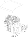
Fig. 3 shows a perspective view of a range extender to be placed in a moveable frame of the chassis ofFig. 2 ; -
Fig. 4 shows a perspective view of a moveable frame of the chassis ofFig. 2 ; -
Fig. 5A shows a perspective view of the moveable frame ofFig. 4 mounted to a portion of the chassis ofFig. 2 , the moveable frame being in a retracted position; -
Fig. 5B shows a perspective view of the moveable frame ofFig. 4 mounted to a portion of the chassis ofFig. 2 , the moveable frame being in a deployed position; -
Fig. 6A is a detail ofFig. 4 showing a locking mechanism of the moveable frame, the locking mechanism being in a locking position; -
Fig. 6B shows the locking mechanism ofFig. 6A , the locking mechanism being in a release position; and -
Fig. 7 shows a perspective view of the moveable frame mounted to a portion of a chassis in accordance with a further embodiment of the present invention, the moveable frame being in the retracted position. -
Fig. 1 shows an exemplary commercial REEV, namely an electric delivery truck 1, comprising achassis 10 according to an embodiment of the present invention. It should be noted that thechassis 10 according to the present invention could be used in any other kind of REEV, such as an electric coach or an electric city bus for example. - The
chassis 10 is depicted in more detail inFig. 2 . Thechassis 10 is described herein with reference to the major axes of the delivery truck 1, namely a longitudinal axis X, a transverse axis Y and a vertical axis Z (shown inFig. 1 andFig. 2 ). Moreover, references herein to "left" and "right" refer to the corresponding sides of the delivery truck 1 when looking from the rear of the delivery truck 1 towards the front. - The
chassis 10 comprises astructure 10a extending along the longitudinal axis X and including a pair of left andright chassis rails 11, to which are mounted afront drivetrain module 12, arear drivetrain module 13, first and second highvoltage battery packs range extender 16. - The
front drivetrain module 12 comprises a frontelectric motor 17 and afront gearbox 18 which drivefront wheels 19 mounted onfront suspension arms 20. Similarly, therear drivetrain module 13 comprises a rearelectric motor 21 and a rear gearbox 22 which driverear wheels 23 mounted onrear suspension arms 24. - The first high
voltage battery pack 14 is mounted between the left andright chassis rails 11 and the second highvoltage battery pack 15 is mounted on a longitudinal right side of thechassis 10, on an outside of theright chassis rail 11. Therange extender 16 is mounted on an opposite side of thechassis 10 to the second highvoltage battery pack 15, on a longitudinal left side of thechassis 10, on an outside of theleft chassis rail 11. As will be explained in more detail below, therange extender 16 is arranged in thechassis 10 such that therange extender 16 can be easily moved outwards away from the rest of thechassis 10, for example for servicing or in order to be more easily removed from thechassis 10 and replaced e.g. by a battery pack. - The
range extender 16 is illustrated in more detail inFig. 3 . Therange extender 16 comprises anelectric generator 25 driven by aninternal combustion engine 26. Theelectric generator 25 and theinternal combustion engine 26 are mechanically connected to each other such that theelectric generator 25 and theinternal combustion engine 26 form a single unit. As shown inFig. 3 , thegenerator 25 is for example bolted to theinternal combustion engine 26. In the exemplary embodiment shown, therange extender 16 includes a plurality of self-contained electrical and fluid connectors. Theexemplary range extender 16 also comprises a high voltageelectrical connector 26a to connect therange extender 16 to a control unit (not shown) of the vehicle. The high voltageelectrical connector 26a comprises a 3-phase output 26b and includesoutput cables 26c which are preferably long enough to facilitate the removal of therange extender 16 from thechassis 10, or at least for therange extender 16 to be moved outwards a predetermined distance away from thechassis 10. Theexemplary range extender 16 also includes alow voltage connector 26d. Therange extender 16 also includes a fuel connector linked to a fuel tank 27 (visible inFig. 2 ) to provide fuel to theinternal combustion engine 26. - In the embodiment described herein, the
range extender 16 is provided to recharge the first and/or the second high voltage battery packs 14, 15 when the charge of the batteries of the battery packs 14, 15 is getting low. However, therange extender 16 may also be connected to the front and/or rear electric motor(s) 17, 21 to provide power directly to the electric motor(s) 17, 21. Therange extender 16 described herein operates with an internal combustion engine. However, therange extender 16 could be operated by other electricity generation means, such as fuel cells for example. - The
range extender 16 is arranged in a supportingframe 28 which is slidably mounted to thestructure 10a of thechassis 10. Theframe 28 is illustrated in more detail inFig. 4 ,Fig. 5A andFig. 5B . Theframe 28 is mounted to the longitudinal left side of thestructure 10a of thechassis 10. Theframe 28 is mounted in the region of a midpoint of the longitudinal left side of thestructure 10a. That is, theframe 28 is located, along the longitudinal axis X, between thefront drivetrain module 12 and therear drivetrain module 13. This location of theframe 28 allows therange extender 16 to be easily accessible from the outside, for example for maintenance of therange extender 16. This location of theframe 28 also allows theelectric motors gearboxes 18, 22 to remain positioned at the front and at the rear of the vehicle, which is required in electric four wheel drive vehicles and also to fullfill NVH requirements. Furthermore, this configuration allows an even weight distribution on the vehicle between the front and rear axles. - As shown in
Fig. 4 , theframe 28 comprises a firstvertical wall 29, a secondvertical wall 30, a firsthorizontal bottom bar 31 and a secondhorizontal bottom bar 32. The first and second bottom bars 31, 32 extend between the first andsecond walls second walls second walls empty volume 33 configured to receive therange extender 16. A pair of mountingbrackets 33a are fixed to thesecond wall 30 and secure therange extender 16 to theframe 28 when therange extender 16 locates in thevolume 33. In alternative arrangements, the mountingbrackets 33a are fixed to thefirst wall 29 or on both first andsecond walls brackets 33a are configured to secure therange extender 16 to theframe 28. In one embodiment, the mountingbrackets 33a maybe adjustable such that the mountingbrackets 33a can secure a battery pack to theframe 28 when therange extender 16 is replaced by such a battery pack in thevolume 33. Moreover, the mountingbrackets 33a maybe adjustable so that different types of range extenders and/or range extenders of various sizes can be secured in theframe 28. These may includerange extenders 16 having different types of and/or sizes ofengines 26 or other power source to drive theelectric generator 25 of therange extender 16. - On the outside of the
first wall 29 is provided afirst compartment 34 configured to accommodate thefuel tank 27. On the outside of thesecond wall 30 is provided asecond compartment 35 configured to accomodate aradiator 35a andfan assembly 35b (shown inFig. 2 ). Therefore, therange extender 16 and all the components required to operate therange extender 16 are provided on the slidingframe 28, and the only connection between theranger extender 16 and other components of the vehicle in thestructure 10a consists in the high andlow voltage connectors - A cover 36 (visible in
Fig. 2 andFig. 3 ) is provided above thevolume 33 to protect therange extender 16 from mechanical damages when therange extender 16 locates in theframe 28. - The
frame 28 is slideable relative to thestructure 10a along a direction transverse to the longitudinal axis X. In particular, theframe 28 is slideable along the transverse axis Y. Theframe 28 is slideable between a retracted position and a deployed or extended position. Theframe 28 moves outward from thestructure 10a along the transverse axis Y when theframe 28 is pulled from the retracted position towards the deployed position. - The
frame 28 is mounted to afirst arm 37 and asecond arm 38 which are secured to the longitudinal left side of thestructure 10a. The first andsecond arms second arms structure 10a substantially parallel to the transverse axis Y. - The first and
second walls second arms telescopic guide 39 will be described. The firsttelescopic guide 39 comprises aguide rail 41 fixed to thefirst arm 37 and a sliding bar orslider 42 fixed to thefirst wall 29 of theframe 28. Theguide rail 41 is bolted to thefirst arm 37. Likewise, theslider 42 is bolted to thefirst wall 29. Anintermediate component 43 is arranged between theguide rail 41 and theslider 42 and designed to slide along theguide rail 41 and theslider 42. The telescopic guides 39, 40 allow theframe 28 to be slideable relative to thestructure 10a, between the retracted position and the deployed position. The guide rails 41, theintermediate components 43 and thesliders 42 forming the telescopic guides 39, 40 are preferably made of aluminium. Alternatively, the telescopic guides 39, 40 may be made of steel. - A first and
second locking mechanisms frame 28 to lock theframe 28 in the retracted position. The first andsecond locking mechanisms latches 46 movable between a locking position and a release position and biased towards the locking position. In the locking position, thelatches 46 locate inapertures 47 formed in thearms frame 28 is locked in the retracted position. Therefore, in the locking position, thelatches 46 prevent theframe 28 from moving relative to thestructure 10a. To unlock theframe 28 and enable theframe 28 to be pulled from the retracted position towards the deployed position, thelatches 46 are moved towards the release position, i.e. pulled away from theapertures 47. The first andsecond locking mechanisms frame 28, however, the first and/orsecond locking mechanisms second arms - Advantageously, a stop member is provided in each
telescopic guide frame 28 is configured to engage the stop members when theframe 28 reaches the deployed position, to prevent theframe 28 from moving beyong the deployed position, out of thestructure 10a. - The
slideable frame 28 helps to improve the accessibility of therange extender 16. For example, the slidingframe 28 enables therange extender 16 to be easily slid outwards for maintenance. In conventional lorries, the internal combustion engine, which is the main element which requires regular servicing, is placed under the cabin and the cabin is tilted forward for access to the internal combustion engine. In the delivery truck 1 incorporating thechassis 10 according to the present invention, the internal combustion engine, part of therange extender 16, is located on the side of the delivery truck 1, in the slidingframe 28, and under the cabin are located all the electric drive components, which necessitate little maintenance and therefore do not require to be easily accessible. Therefore, to maintain the internal combustion engine, no tilting cabin is needed, which makes the truck design much simpler. - The delivery truck 1 described herein may use the
range extender 16 for long distance journeys, to supplement the battery packs when the charge of the batteries of the battery packs are getting low. For shorter distances, e.g. city route deliveries, therange extender 16 may be easily swapped out from thechassis 10 and replaced by a battery pack. The delivery truck 1 according to the present invention can therefore be adapted for long distance use, using therange extender 16, and for shorter distance use, by replacing therange extender 16 by a battery pack. - Furthermore, the
slidable frame 28 enables therange extender 16 to be easily taken out of thechassis 10 or swapped out of thechassis 10 to be replaced by a range extender of a different type or size. - As mentioned above, the
range extender 16 consists in a self-contained unit. This makes therange extender 16 easy to remove from thechassis 10 since only the high and low voltageelectrical connectors range extender 16 from thechassis 10. - The
frame 28 is configured to support the weight of therange extender 16, which is similar to the weight of each battery pack, for example a weight of around 330 - 340kg kg. - A
chassis 100 according to a further embodiment of the present invention is shown inFig. 7 , which corresponds closely to the first embodiment described above. Like reference numerals have been used for like components. Some differences in relation to the first embodiment are described below. - In the embodiment shown in
Fig. 7 , thechassis 100 comprises first andsecond frame actuators 48 for automatically actuating theframe 28 between the retracted and extended positions. It will be appreciated that theframe actuators 48 are shown schematically inFig. 7 and so do not represent the actual physical structure thatsuch actuators 48 may comprise. Eachframe actuator 48 may be an electrical or pneumatic or hydraulic actuator. For example, theframe actuator 48 may be in the form of a motor with a cog and a toothed strip on theslider 42. Alternatively, theframe actuator 48 may be in the form of a piston to drive and retract theframe 28. - The
chassis 100 comprises first and secondlocking mechanism actuators 49 for automatically actuating the lockingmechanisms locking mechanism actuator 49 may be an electrical or pneumatic or hydraulic actuator. For example, thelocking mechanism actuator 49 is in the form of a solenoid actuator. - The
chassis 100 comprises means 50 for detecting if theframe 28 is in the retracted position and/or if the lockingmechanisms means 50 is shown schematically inFig. 7 and so does not represent the actual physical structure that such detectingmeans 50 may comprise. The detecting mean may comprise an optical sensor configured to detect the position of theframe 28, for example a position of a refertence point on theframe 28. The detecting means 50 may be a detector in the form of an electrical switch, which may be actuated in dependence on the position of theframe 28. The detecting means may be electrically connected to the vehicle cabin. The detecting means 50 may comprise an alert means to identify if theframe 28 is unlocked and/or is in the deployed position. Such alert means may be configured to alert the vehicle operator that the vehicle must not to be driven if theframe 28 is not locked and/or in the retracted position. Such alert means may comprise a warning light and/or an audible alert. The vehicle may be configured such that the vehicle is inoperable if the detectingmeans 50 identifies that theframe 28 is unlocked and/or is in the deployed position. For example, the vehicle may comprise a controller which controls operation of the vehicle, which is configured to render the vehicle inoperable if the detectingmeans 50 identifies that theframe 28 is unlocked and/or is in the deployed position. For example, the vehicle may comprise an immobiliser which immobilises the vehicle if the detectingmeans 50 identifies that theframe 28 is unlocked and/or is in the deployed position. - As used herein, the term electric vehicle is intended to comprise any vehicle that may be at least partially powered by electricity, and can include, although is not limited to, plug-in electric vehicles, range extender electric vehicles, hybrid electric vehicles, and plug-in hybrid electric vechicles. It will be appreciated that it may be desirable for a vehicle or vehicle chassis to be adaptable between these different types of electric vehicle. This may be to enable use of a common chassis to manufacture different types of electric vehicle, thereby reducing manufacturing costs, or for a vehicle to be modified after manufacture to different power configurations, for example between a plug-ine electric vehicle to a range extender electric vehicle. This may be desirable, for example, in fleet use, to adapt a vehicle between urban use, in which plug-in electric power is desired without the need to carry the weight of a range extender around with the vehicle, to a range extender electric vehicle for longer-range use where the range extender would be necessary.
- Although the chassis structure in the exemplary embodiment comprises a pair of spaced parallel chassis rails, it will be appreciated that the chassis of the invention is not intended to be limited to this particular configuration of vehicle chassis, and may comprise any other configuration of electric vehicle chassis structure having a longitudinal axis and to which a frame is movably mounted.
- The embodiment of the invention shown in the drawings and described above are exemplary embodiments only and are not intended to limit the scope of the invention, which is defined by the claims.
Claims (15)
- An electric vehicle chassis (10) comprising:a structure extending along a longitudinal axis (X); anda frame (28) for accommodating an on-board auxiliary power unit or a range extender (16), the frame (28) being located on the longitudinal axis (X) and mounted in the region of a midpoint of said longitudinal axis (X) between a front drivetrain module (12) and a rear drivetrain module (13);wherein the frame (28) is moveably mounted to the structure and is moveable relative to the structure between a retracted position and a deployed position and wherein the frame (28) is moveable outward from the structure from the retracted position towards the deployed position.
- A chassis (10) according to claim 1, wherein the frame (28) is slideable between the retracted position and the deployed position.
- A chassis (10) according to claim 2, wherein the structure comprises a first arm (37) and a second arm (38), wherein the frame (28) comprises a first wall (29) and a second wall (30), the first and second walls (29, 30) extending substantially parallel to each other, and wherein the first and second walls (29, 30) are arranged to travel respectively along the first and second arms (37, 38) when the frame (28) is moved between the retracted position and the deployed position.
- A chassis (10) according to claim 3, wherein the first and second walls (29, 30) and the first and second arms (37, 38) are respectively connected to each other by means of first and second telescopic guides (39, 40).
- A chassis (10) according to any preceding claim, wherein the frame (28) is moveable relative to the structure in a direction transverse (Y) to the longitudinal axis (X).
- A chassis (10) according to any preceding claim, comprising a frame actuator (48) for automatically actuating the frame (28) between the retracted and deployed positions, optionally wherein the frame actuator (48) comprises an electrical or pneumatic or hydraulic actuator.
- A chassis (10) according to any preceding claim, comprising means for detecting if the frame (28) is in the retracted position.
- A chassis (10) according to any preceding claim, comprising a locking mechanism (44, 45) to lock the frame (28) in the retracted position.
- A chassis (10) according to claim 8, wherein the locking mechanism (44, 45) is moveable between a locking position and a release position, and wherein the locking mechanism (44, 45) is biased towards the locking position.
- A chassis (10) according to claim 9, comprising a locking mechanism actuator (49) for automatically actuating the locking mechanism (44, 45) between the locking and release positions, optionally wherein the locking mechanism actuator (49) comprises an electrical or pneumatic or hydraulic actuator.
- A chassis (10) according to any preceding claim, wherein the frame (28) comprises one or more mounting brackets (33a) for securing the range extender (16) to the frame (28).
- A chassis (10) according to claim 11, wherein the one or more mounting brackets (33a) are adjustable such that a battery pack or a different type of range extender (16) can be secured to the frame (28) by means of the one or more mounting brackets (33a).
- A chassis (10) according to any preceding claim, comprising a range extender (16) mounted to the frame (28), optionally wherein the range extender (16) is removably mounted to the frame (28).
- An electric vehicle comprising a chassis (10) according to any preceding claim.
- An electric vehicle according to claim 14, comprising one or more electrical connectors (26a, 26d) for connecting the range extender (16) to vehicle components in the chassis (10), wherein the only connection between the range extender (16) and said vehicle components are said one or more electrical connectors (26a, 26d).
Applications Claiming Priority (2)
| Application Number | Priority Date | Filing Date | Title |
|---|---|---|---|
| GB1609528.3A GB2554340B (en) | 2016-05-31 | 2016-05-31 | Electric vehicle chassis |
| PCT/GB2017/051495 WO2017207970A1 (en) | 2016-05-31 | 2017-05-25 | Electric vehicle chassis |
Publications (2)
| Publication Number | Publication Date |
|---|---|
| EP3464029A1 EP3464029A1 (en) | 2019-04-10 |
| EP3464029B1 true EP3464029B1 (en) | 2022-03-23 |
Family
ID=56410785
Family Applications (1)
| Application Number | Title | Priority Date | Filing Date |
|---|---|---|---|
| EP17727334.9A Not-in-force EP3464029B1 (en) | 2016-05-31 | 2017-05-25 | Electric vehicle chassis |
Country Status (3)
| Country | Link |
|---|---|
| EP (1) | EP3464029B1 (en) |
| GB (1) | GB2554340B (en) |
| WO (1) | WO2017207970A1 (en) |
Families Citing this family (7)
| Publication number | Priority date | Publication date | Assignee | Title |
|---|---|---|---|---|
| CN108621810B (en) * | 2018-04-24 | 2020-08-28 | 浙江吉利控股集团有限公司 | Multi-range extender vehicle and multi-range extender distribution method |
| CN108706107B (en) * | 2018-08-01 | 2024-02-20 | 中电科芜湖通用航空产业技术研究院有限公司 | Vibration test system of hybrid power device |
| CN108715229B (en) * | 2018-08-01 | 2024-01-26 | 中电科芜湖通用航空产业技术研究院有限公司 | Integrated mounting system for power device of hybrid power aircraft |
| TWI683756B (en) * | 2019-01-28 | 2020-02-01 | 國立臺灣師範大學 | Vehicle chassis |
| RU191010U1 (en) * | 2019-02-11 | 2019-07-18 | Публичное акционерное общество "КАМАЗ" | Electric wheeled vehicle |
| CN113677556B (en) * | 2019-03-26 | 2024-12-24 | 沃尔沃卡车集团 | Equipment, systems and vehicles for installation of traction batteries |
| EP4155103B1 (en) | 2019-04-04 | 2025-01-15 | Volvo Truck Corporation | A system and a method for installation of traction batteries for a vehicle |
Family Cites Families (12)
| Publication number | Priority date | Publication date | Assignee | Title |
|---|---|---|---|---|
| US3799063A (en) * | 1972-08-16 | 1974-03-26 | D Reed | Vehicle battery changing device |
| US4231444A (en) * | 1978-08-28 | 1980-11-04 | Telesio George O | Mechanical interfaces for control linkages in a removable vehicle engine module |
| US5301765A (en) * | 1993-05-14 | 1994-04-12 | Swanson Lennart H | Battery pack installation and storage system for electric vehicles |
| RU2081758C1 (en) * | 1994-04-08 | 1997-06-20 | Эдуард Дмитриевич Житников | Small-size road vehicle |
| US5845734A (en) * | 1997-07-28 | 1998-12-08 | Ford Global Technologies, Inc. | Slide out engine mounting system for automotive vehicle |
| DE102006002086A1 (en) * | 2006-01-17 | 2007-07-19 | Franz Forster | Work machine for use as battery electrically telescopic forklift, has hydrostatic traction drive provided as main drive, and electrical traction drive provided as switchable or operatable auxiliary drive at position of main drive |
| US20070221431A1 (en) * | 2006-03-22 | 2007-09-27 | Dunamis Power Systems, Inc. | Auxiliary power unit for a vehicle |
| US20080023965A1 (en) * | 2006-07-25 | 2008-01-31 | Black Roak Systems Llc | Auxiliary power unit for transportation vehicle |
| JP4985361B2 (en) * | 2007-11-30 | 2012-07-25 | 三菱自動車工業株式会社 | Electric car |
| FR2941179A1 (en) * | 2009-01-16 | 2010-07-23 | Renault Sas | ARRANGEMENT OF AN EXTENDER OF AUTONOMY ON AN ELECTRIC MOTOR VEHICLE |
| DE102012108768A1 (en) * | 2012-09-18 | 2014-03-20 | Gottwald Port Technology Gmbh | Battery Electric Tractor Trailer for ISO Container Transport |
| US9522674B2 (en) * | 2013-03-26 | 2016-12-20 | Honda Motor Co., Ltd. | Internal combustion engine control device and internal combustion engine control method |
-
2016
- 2016-05-31 GB GB1609528.3A patent/GB2554340B/en not_active Expired - Fee Related
-
2017
- 2017-05-25 EP EP17727334.9A patent/EP3464029B1/en not_active Not-in-force
- 2017-05-25 WO PCT/GB2017/051495 patent/WO2017207970A1/en not_active Ceased
Also Published As
| Publication number | Publication date |
|---|---|
| GB2554340A (en) | 2018-04-04 |
| GB201609528D0 (en) | 2016-07-13 |
| EP3464029A1 (en) | 2019-04-10 |
| WO2017207970A1 (en) | 2017-12-07 |
| GB2554340B (en) | 2022-05-11 |
Similar Documents
| Publication | Publication Date | Title |
|---|---|---|
| EP3464029A1 (en) | Electric vehicle chassis | |
| EP3805027B1 (en) | Electric vehicle | |
| US12403794B2 (en) | Electric vehicle battery unit and battery unit installation method | |
| JP5499055B2 (en) | Engine electric hybrid vehicle battery and fuel tank mounting structure | |
| US7854282B2 (en) | Hybrid electric vehicle | |
| CN108367660B (en) | Mounting structure of high-voltage control equipment unit | |
| US9472791B2 (en) | Battery system, housing and vehicle including battery system | |
| JP5807476B2 (en) | Electric vehicle battery pack support structure | |
| US8347995B2 (en) | Automobile provided with a power supply battery which is removable by a vertical movement, and device for installing and removing such a battery | |
| EP3778279B1 (en) | Vehicle comprising two side rails and a battery housing | |
| CN110920416A (en) | electric vehicle | |
| CN104786803A (en) | High driving range all-electric logistics vehicle structure | |
| WO1979000630A1 (en) | Electrically driven vehicles | |
| CN110014878B (en) | Electric Motor Driven Vehicles | |
| US20200231050A1 (en) | Electric vehicle | |
| CN112074427A (en) | Energy storage system for a vehicle | |
| CN110254198A (en) | Protectiveness retainer component for electrified vehicle battery packs | |
| JP2020083221A (en) | Automatic drive vehicle | |
| EP4574493A1 (en) | Hybrid or electric road vehicle with modular containers for high-voltage electric/electronic components | |
| JP2015168380A (en) | electric vehicle | |
| JP2013086609A (en) | Vehicular battery pack | |
| JP2013193652A (en) | Electric vehicle | |
| US12187367B2 (en) | Trailer | |
| CN204659429U (en) | A kind of after poppet for the pure electronic logistic car of high continual mileage | |
| CN121625758A (en) | Plug-in hybrid vehicles |
Legal Events
| Date | Code | Title | Description |
|---|---|---|---|
| STAA | Information on the status of an ep patent application or granted ep patent |
Free format text: STATUS: UNKNOWN |
|
| STAA | Information on the status of an ep patent application or granted ep patent |
Free format text: STATUS: THE INTERNATIONAL PUBLICATION HAS BEEN MADE |
|
| PUAI | Public reference made under article 153(3) epc to a published international application that has entered the european phase |
Free format text: ORIGINAL CODE: 0009012 |
|
| STAA | Information on the status of an ep patent application or granted ep patent |
Free format text: STATUS: REQUEST FOR EXAMINATION WAS MADE |
|
| 17P | Request for examination filed |
Effective date: 20181220 |
|
| AK | Designated contracting states |
Kind code of ref document: A1 Designated state(s): AL AT BE BG CH CY CZ DE DK EE ES FI FR GB GR HR HU IE IS IT LI LT LU LV MC MK MT NL NO PL PT RO RS SE SI SK SM TR |
|
| AX | Request for extension of the european patent |
Extension state: BA ME |
|
| DAV | Request for validation of the european patent (deleted) | ||
| DAX | Request for extension of the european patent (deleted) | ||
| STAA | Information on the status of an ep patent application or granted ep patent |
Free format text: STATUS: EXAMINATION IS IN PROGRESS |
|
| 17Q | First examination report despatched |
Effective date: 20200915 |
|
| REG | Reference to a national code |
Ref country code: DE Ref legal event code: R079 Ref document number: 602017054905 Country of ref document: DE Free format text: PREVIOUS MAIN CLASS: B62D0021020000 Ipc: B60K0005020000 |
|
| GRAP | Despatch of communication of intention to grant a patent |
Free format text: ORIGINAL CODE: EPIDOSNIGR1 |
|
| STAA | Information on the status of an ep patent application or granted ep patent |
Free format text: STATUS: GRANT OF PATENT IS INTENDED |
|
| RIC1 | Information provided on ipc code assigned before grant |
Ipc: B60L 50/16 20190101ALI20220104BHEP Ipc: B62D 21/02 20060101ALI20220104BHEP Ipc: B60L 50/61 20190101ALI20220104BHEP Ipc: B60K 5/00 20060101ALI20220104BHEP Ipc: B60K 5/12 20060101ALI20220104BHEP Ipc: B60K 5/10 20060101ALI20220104BHEP Ipc: B60K 5/02 20060101AFI20220104BHEP |
|
| GRAS | Grant fee paid |
Free format text: ORIGINAL CODE: EPIDOSNIGR3 |
|
| INTG | Intention to grant announced |
Effective date: 20220119 |
|
| GRAA | (expected) grant |
Free format text: ORIGINAL CODE: 0009210 |
|
| STAA | Information on the status of an ep patent application or granted ep patent |
Free format text: STATUS: THE PATENT HAS BEEN GRANTED |
|
| AK | Designated contracting states |
Kind code of ref document: B1 Designated state(s): AL AT BE BG CH CY CZ DE DK EE ES FI FR GB GR HR HU IE IS IT LI LT LU LV MC MK MT NL NO PL PT RO RS SE SI SK SM TR |
|
| REG | Reference to a national code |
Ref country code: GB Ref legal event code: FG4D |
|
| REG | Reference to a national code |
Ref country code: CH Ref legal event code: EP |
|
| REG | Reference to a national code |
Ref country code: DE Ref legal event code: R096 Ref document number: 602017054905 Country of ref document: DE |
|
| REG | Reference to a national code |
Ref country code: IE Ref legal event code: FG4D |
|
| REG | Reference to a national code |
Ref country code: AT Ref legal event code: REF Ref document number: 1477207 Country of ref document: AT Kind code of ref document: T Effective date: 20220415 |
|
| REG | Reference to a national code |
Ref country code: LT Ref legal event code: MG9D |
|
| REG | Reference to a national code |
Ref country code: NL Ref legal event code: MP Effective date: 20220323 |
|
| PG25 | Lapsed in a contracting state [announced via postgrant information from national office to epo] |
Ref country code: SE Free format text: LAPSE BECAUSE OF FAILURE TO SUBMIT A TRANSLATION OF THE DESCRIPTION OR TO PAY THE FEE WITHIN THE PRESCRIBED TIME-LIMIT Effective date: 20220323 Ref country code: RS Free format text: LAPSE BECAUSE OF FAILURE TO SUBMIT A TRANSLATION OF THE DESCRIPTION OR TO PAY THE FEE WITHIN THE PRESCRIBED TIME-LIMIT Effective date: 20220323 Ref country code: NO Free format text: LAPSE BECAUSE OF FAILURE TO SUBMIT A TRANSLATION OF THE DESCRIPTION OR TO PAY THE FEE WITHIN THE PRESCRIBED TIME-LIMIT Effective date: 20220623 Ref country code: LT Free format text: LAPSE BECAUSE OF FAILURE TO SUBMIT A TRANSLATION OF THE DESCRIPTION OR TO PAY THE FEE WITHIN THE PRESCRIBED TIME-LIMIT Effective date: 20220323 Ref country code: HR Free format text: LAPSE BECAUSE OF FAILURE TO SUBMIT A TRANSLATION OF THE DESCRIPTION OR TO PAY THE FEE WITHIN THE PRESCRIBED TIME-LIMIT Effective date: 20220323 Ref country code: BG Free format text: LAPSE BECAUSE OF FAILURE TO SUBMIT A TRANSLATION OF THE DESCRIPTION OR TO PAY THE FEE WITHIN THE PRESCRIBED TIME-LIMIT Effective date: 20220623 |
|
| REG | Reference to a national code |
Ref country code: AT Ref legal event code: MK05 Ref document number: 1477207 Country of ref document: AT Kind code of ref document: T Effective date: 20220323 |
|
| PG25 | Lapsed in a contracting state [announced via postgrant information from national office to epo] |
Ref country code: LV Free format text: LAPSE BECAUSE OF FAILURE TO SUBMIT A TRANSLATION OF THE DESCRIPTION OR TO PAY THE FEE WITHIN THE PRESCRIBED TIME-LIMIT Effective date: 20220323 Ref country code: GR Free format text: LAPSE BECAUSE OF FAILURE TO SUBMIT A TRANSLATION OF THE DESCRIPTION OR TO PAY THE FEE WITHIN THE PRESCRIBED TIME-LIMIT Effective date: 20220624 Ref country code: FI Free format text: LAPSE BECAUSE OF FAILURE TO SUBMIT A TRANSLATION OF THE DESCRIPTION OR TO PAY THE FEE WITHIN THE PRESCRIBED TIME-LIMIT Effective date: 20220323 |
|
| PG25 | Lapsed in a contracting state [announced via postgrant information from national office to epo] |
Ref country code: NL Free format text: LAPSE BECAUSE OF FAILURE TO SUBMIT A TRANSLATION OF THE DESCRIPTION OR TO PAY THE FEE WITHIN THE PRESCRIBED TIME-LIMIT Effective date: 20220323 |
|
| PG25 | Lapsed in a contracting state [announced via postgrant information from national office to epo] |
Ref country code: SM Free format text: LAPSE BECAUSE OF FAILURE TO SUBMIT A TRANSLATION OF THE DESCRIPTION OR TO PAY THE FEE WITHIN THE PRESCRIBED TIME-LIMIT Effective date: 20220323 Ref country code: SK Free format text: LAPSE BECAUSE OF FAILURE TO SUBMIT A TRANSLATION OF THE DESCRIPTION OR TO PAY THE FEE WITHIN THE PRESCRIBED TIME-LIMIT Effective date: 20220323 Ref country code: RO Free format text: LAPSE BECAUSE OF FAILURE TO SUBMIT A TRANSLATION OF THE DESCRIPTION OR TO PAY THE FEE WITHIN THE PRESCRIBED TIME-LIMIT Effective date: 20220323 Ref country code: PT Free format text: LAPSE BECAUSE OF FAILURE TO SUBMIT A TRANSLATION OF THE DESCRIPTION OR TO PAY THE FEE WITHIN THE PRESCRIBED TIME-LIMIT Effective date: 20220725 Ref country code: ES Free format text: LAPSE BECAUSE OF FAILURE TO SUBMIT A TRANSLATION OF THE DESCRIPTION OR TO PAY THE FEE WITHIN THE PRESCRIBED TIME-LIMIT Effective date: 20220323 Ref country code: EE Free format text: LAPSE BECAUSE OF FAILURE TO SUBMIT A TRANSLATION OF THE DESCRIPTION OR TO PAY THE FEE WITHIN THE PRESCRIBED TIME-LIMIT Effective date: 20220323 Ref country code: CZ Free format text: LAPSE BECAUSE OF FAILURE TO SUBMIT A TRANSLATION OF THE DESCRIPTION OR TO PAY THE FEE WITHIN THE PRESCRIBED TIME-LIMIT Effective date: 20220323 Ref country code: AT Free format text: LAPSE BECAUSE OF FAILURE TO SUBMIT A TRANSLATION OF THE DESCRIPTION OR TO PAY THE FEE WITHIN THE PRESCRIBED TIME-LIMIT Effective date: 20220323 |
|
| PG25 | Lapsed in a contracting state [announced via postgrant information from national office to epo] |
Ref country code: PL Free format text: LAPSE BECAUSE OF FAILURE TO SUBMIT A TRANSLATION OF THE DESCRIPTION OR TO PAY THE FEE WITHIN THE PRESCRIBED TIME-LIMIT Effective date: 20220323 Ref country code: IS Free format text: LAPSE BECAUSE OF FAILURE TO SUBMIT A TRANSLATION OF THE DESCRIPTION OR TO PAY THE FEE WITHIN THE PRESCRIBED TIME-LIMIT Effective date: 20220723 Ref country code: AL Free format text: LAPSE BECAUSE OF FAILURE TO SUBMIT A TRANSLATION OF THE DESCRIPTION OR TO PAY THE FEE WITHIN THE PRESCRIBED TIME-LIMIT Effective date: 20220323 |
|
| REG | Reference to a national code |
Ref country code: CH Ref legal event code: PL |
|
| REG | Reference to a national code |
Ref country code: DE Ref legal event code: R097 Ref document number: 602017054905 Country of ref document: DE |
|
| REG | Reference to a national code |
Ref country code: BE Ref legal event code: MM Effective date: 20220531 |
|
| PLBE | No opposition filed within time limit |
Free format text: ORIGINAL CODE: 0009261 |
|
| STAA | Information on the status of an ep patent application or granted ep patent |
Free format text: STATUS: NO OPPOSITION FILED WITHIN TIME LIMIT |
|
| PG25 | Lapsed in a contracting state [announced via postgrant information from national office to epo] |
Ref country code: MC Free format text: LAPSE BECAUSE OF FAILURE TO SUBMIT A TRANSLATION OF THE DESCRIPTION OR TO PAY THE FEE WITHIN THE PRESCRIBED TIME-LIMIT Effective date: 20220323 Ref country code: LU Free format text: LAPSE BECAUSE OF NON-PAYMENT OF DUE FEES Effective date: 20220525 Ref country code: LI Free format text: LAPSE BECAUSE OF NON-PAYMENT OF DUE FEES Effective date: 20220531 Ref country code: DK Free format text: LAPSE BECAUSE OF FAILURE TO SUBMIT A TRANSLATION OF THE DESCRIPTION OR TO PAY THE FEE WITHIN THE PRESCRIBED TIME-LIMIT Effective date: 20220323 Ref country code: CH Free format text: LAPSE BECAUSE OF NON-PAYMENT OF DUE FEES Effective date: 20220531 |
|
| 26N | No opposition filed |
Effective date: 20230102 |
|
| PG25 | Lapsed in a contracting state [announced via postgrant information from national office to epo] |
Ref country code: IE Free format text: LAPSE BECAUSE OF NON-PAYMENT OF DUE FEES Effective date: 20220525 |
|
| PG25 | Lapsed in a contracting state [announced via postgrant information from national office to epo] |
Ref country code: SI Free format text: LAPSE BECAUSE OF FAILURE TO SUBMIT A TRANSLATION OF THE DESCRIPTION OR TO PAY THE FEE WITHIN THE PRESCRIBED TIME-LIMIT Effective date: 20220323 Ref country code: BE Free format text: LAPSE BECAUSE OF NON-PAYMENT OF DUE FEES Effective date: 20220531 |
|
| P01 | Opt-out of the competence of the unified patent court (upc) registered |
Effective date: 20230523 |
|
| PG25 | Lapsed in a contracting state [announced via postgrant information from national office to epo] |
Ref country code: IT Free format text: LAPSE BECAUSE OF FAILURE TO SUBMIT A TRANSLATION OF THE DESCRIPTION OR TO PAY THE FEE WITHIN THE PRESCRIBED TIME-LIMIT Effective date: 20220323 |
|
| REG | Reference to a national code |
Ref country code: GB Ref legal event code: 732E Free format text: REGISTERED BETWEEN 20230901 AND 20230906 |
|
| REG | Reference to a national code |
Ref country code: GB Ref legal event code: 732E Free format text: REGISTERED BETWEEN 20231130 AND 20231206 |
|
| PGFP | Annual fee paid to national office [announced via postgrant information from national office to epo] |
Ref country code: GB Payment date: 20231116 Year of fee payment: 7 |
|
| PGFP | Annual fee paid to national office [announced via postgrant information from national office to epo] |
Ref country code: FR Payment date: 20231117 Year of fee payment: 7 Ref country code: DE Payment date: 20231121 Year of fee payment: 7 |
|
| PG25 | Lapsed in a contracting state [announced via postgrant information from national office to epo] |
Ref country code: HU Free format text: LAPSE BECAUSE OF FAILURE TO SUBMIT A TRANSLATION OF THE DESCRIPTION OR TO PAY THE FEE WITHIN THE PRESCRIBED TIME-LIMIT; INVALID AB INITIO Effective date: 20170525 |
|
| PG25 | Lapsed in a contracting state [announced via postgrant information from national office to epo] |
Ref country code: MK Free format text: LAPSE BECAUSE OF FAILURE TO SUBMIT A TRANSLATION OF THE DESCRIPTION OR TO PAY THE FEE WITHIN THE PRESCRIBED TIME-LIMIT Effective date: 20220323 Ref country code: CY Free format text: LAPSE BECAUSE OF FAILURE TO SUBMIT A TRANSLATION OF THE DESCRIPTION OR TO PAY THE FEE WITHIN THE PRESCRIBED TIME-LIMIT Effective date: 20220323 |
|
| PG25 | Lapsed in a contracting state [announced via postgrant information from national office to epo] |
Ref country code: MT Free format text: LAPSE BECAUSE OF FAILURE TO SUBMIT A TRANSLATION OF THE DESCRIPTION OR TO PAY THE FEE WITHIN THE PRESCRIBED TIME-LIMIT Effective date: 20220323 |
|
| REG | Reference to a national code |
Ref country code: DE Ref legal event code: R119 Ref document number: 602017054905 Country of ref document: DE |
|
| GBPC | Gb: european patent ceased through non-payment of renewal fee |
Effective date: 20240525 |
|
| PG25 | Lapsed in a contracting state [announced via postgrant information from national office to epo] |
Ref country code: DE Free format text: LAPSE BECAUSE OF NON-PAYMENT OF DUE FEES Effective date: 20241203 |
|
| PG25 | Lapsed in a contracting state [announced via postgrant information from national office to epo] |
Ref country code: FR Free format text: LAPSE BECAUSE OF NON-PAYMENT OF DUE FEES Effective date: 20240531 |
|
| PG25 | Lapsed in a contracting state [announced via postgrant information from national office to epo] |
Ref country code: GB Free format text: LAPSE BECAUSE OF NON-PAYMENT OF DUE FEES Effective date: 20240525 |
|
| PG25 | Lapsed in a contracting state [announced via postgrant information from national office to epo] |
Ref country code: TR Free format text: LAPSE BECAUSE OF FAILURE TO SUBMIT A TRANSLATION OF THE DESCRIPTION OR TO PAY THE FEE WITHIN THE PRESCRIBED TIME-LIMIT Effective date: 20220323 |