EP3464021B1 - Attachable cart system and method - Google Patents
Attachable cart system and method Download PDFInfo
- Publication number
- EP3464021B1 EP3464021B1 EP17807523.0A EP17807523A EP3464021B1 EP 3464021 B1 EP3464021 B1 EP 3464021B1 EP 17807523 A EP17807523 A EP 17807523A EP 3464021 B1 EP3464021 B1 EP 3464021B1
- Authority
- EP
- European Patent Office
- Prior art keywords
- secure
- cart
- receiver
- assembly
- secure coupling
- Prior art date
- Legal status (The legal status is an assumption and is not a legal conclusion. Google has not performed a legal analysis and makes no representation as to the accuracy of the status listed.)
- Active
Links
Images
















Classifications
-
- B—PERFORMING OPERATIONS; TRANSPORTING
- B62—LAND VEHICLES FOR TRAVELLING OTHERWISE THAN ON RAILS
- B62B—HAND-PROPELLED VEHICLES, e.g. HAND CARTS OR PERAMBULATORS; SLEDGES
- B62B3/00—Hand carts having more than one axis carrying transport wheels; Steering devices therefor; Equipment therefor
- B62B3/02—Hand carts having more than one axis carrying transport wheels; Steering devices therefor; Equipment therefor involving parts being adjustable, collapsible, attachable, detachable or convertible
- B62B3/022—Hand carts having more than one axis carrying transport wheels; Steering devices therefor; Equipment therefor involving parts being adjustable, collapsible, attachable, detachable or convertible folding down the body to the wheel carriage or by retracting projecting parts
-
- B—PERFORMING OPERATIONS; TRANSPORTING
- B60—VEHICLES IN GENERAL
- B60R—VEHICLES, VEHICLE FITTINGS, OR VEHICLE PARTS, NOT OTHERWISE PROVIDED FOR
- B60R9/00—Supplementary fittings on vehicle exterior for carrying loads, e.g. luggage, sports gear or the like
- B60R9/06—Supplementary fittings on vehicle exterior for carrying loads, e.g. luggage, sports gear or the like at vehicle front or rear
-
- B—PERFORMING OPERATIONS; TRANSPORTING
- B62—LAND VEHICLES FOR TRAVELLING OTHERWISE THAN ON RAILS
- B62B—HAND-PROPELLED VEHICLES, e.g. HAND CARTS OR PERAMBULATORS; SLEDGES
- B62B3/00—Hand carts having more than one axis carrying transport wheels; Steering devices therefor; Equipment therefor
- B62B3/002—Hand carts having more than one axis carrying transport wheels; Steering devices therefor; Equipment therefor characterised by a rectangular shape, involving sidewalls or racks
-
- B—PERFORMING OPERATIONS; TRANSPORTING
- B62—LAND VEHICLES FOR TRAVELLING OTHERWISE THAN ON RAILS
- B62B—HAND-PROPELLED VEHICLES, e.g. HAND CARTS OR PERAMBULATORS; SLEDGES
- B62B5/00—Accessories or details specially adapted for hand carts
- B62B5/0003—Adaptations for loading in or on a vehicle
-
- B—PERFORMING OPERATIONS; TRANSPORTING
- B62—LAND VEHICLES FOR TRAVELLING OTHERWISE THAN ON RAILS
- B62B—HAND-PROPELLED VEHICLES, e.g. HAND CARTS OR PERAMBULATORS; SLEDGES
- B62B2203/00—Grasping, holding, supporting the objects
- B62B2203/10—Grasping, holding, supporting the objects comprising lifting means
-
- B—PERFORMING OPERATIONS; TRANSPORTING
- B62—LAND VEHICLES FOR TRAVELLING OTHERWISE THAN ON RAILS
- B62B—HAND-PROPELLED VEHICLES, e.g. HAND CARTS OR PERAMBULATORS; SLEDGES
- B62B2205/00—Hand-propelled vehicles or sledges being foldable or dismountable when not in use
- B62B2205/003—Hand-propelled vehicles or sledges being foldable or dismountable when not in use with actuation mechanisms which drive the folding or unfolding operation
-
- B—PERFORMING OPERATIONS; TRANSPORTING
- B62—LAND VEHICLES FOR TRAVELLING OTHERWISE THAN ON RAILS
- B62B—HAND-PROPELLED VEHICLES, e.g. HAND CARTS OR PERAMBULATORS; SLEDGES
- B62B2205/00—Hand-propelled vehicles or sledges being foldable or dismountable when not in use
- B62B2205/06—Foldable with a scissor-like mechanism
-
- B—PERFORMING OPERATIONS; TRANSPORTING
- B62—LAND VEHICLES FOR TRAVELLING OTHERWISE THAN ON RAILS
- B62B—HAND-PROPELLED VEHICLES, e.g. HAND CARTS OR PERAMBULATORS; SLEDGES
- B62B2205/00—Hand-propelled vehicles or sledges being foldable or dismountable when not in use
- B62B2205/12—Collapsible wheels
-
- B—PERFORMING OPERATIONS; TRANSPORTING
- B62—LAND VEHICLES FOR TRAVELLING OTHERWISE THAN ON RAILS
- B62B—HAND-PROPELLED VEHICLES, e.g. HAND CARTS OR PERAMBULATORS; SLEDGES
- B62B2205/00—Hand-propelled vehicles or sledges being foldable or dismountable when not in use
- B62B2205/14—Retractable wheels
-
- B—PERFORMING OPERATIONS; TRANSPORTING
- B62—LAND VEHICLES FOR TRAVELLING OTHERWISE THAN ON RAILS
- B62B—HAND-PROPELLED VEHICLES, e.g. HAND CARTS OR PERAMBULATORS; SLEDGES
- B62B2205/00—Hand-propelled vehicles or sledges being foldable or dismountable when not in use
- B62B2205/20—Catches; Locking or releasing an articulation
-
- B—PERFORMING OPERATIONS; TRANSPORTING
- B62—LAND VEHICLES FOR TRAVELLING OTHERWISE THAN ON RAILS
- B62B—HAND-PROPELLED VEHICLES, e.g. HAND CARTS OR PERAMBULATORS; SLEDGES
- B62B2206/00—Adjustable or convertible hand-propelled vehicles or sledges
- B62B2206/06—Adjustable or convertible hand-propelled vehicles or sledges adjustable in height
Definitions
- the cart has a vertical positioner to raise and lower the upper portion and lower portion relative to the other.
- the cart may be used as an off-road utility trailer, being towed by a vehicle.
- a transportable utility carrier apparatus for coupling to a transport vehicle including an upper frame, a recessed platform connected to the upper frame, a wheeled base, a lift system interposed between the base and the upper frame for moving the wheeled base relative to the platform between a transport position and a freestanding position, a square hitch tube connected to the upper frame, and a rollered receiver hitch mountable to the transport vehicle.
- the wheels are spaced from the ground in the transport position.
- WO 2016/000042 A1 discloses a mobile cargo carrier for mounting onto the rear of a vehicle, the mobile cargo carrier including a storage container having a wheel arrangement, suspension means for removably connecting the storage container to a rear of a vehicle, the suspension means operable to suspend the storage container from the rear of the vehicle above the road surface and jacking means for vertically displacing the storage container relative to the wheel arrangement.
- a cart and mount secure coupling and receiver system comprising: a cart including: a top deck assembly having a carrying portion, a mount secure coupling and a Secure coupling lock assembly; an undercarriage assembly capable of supporting and adjusting the height of the top deck assembly so that the mount secure coupling is capable of being attached to a secure receiver by the engagement of both the mount secure coupling and the Secure coupling lock assembly.
- a secure receiver comprising: at least one retention tine slot capable of receiving a corresponding at least one mount secure coupling top tine; at least one lower tine reception slot capable of receiving a corresponding at least one mount secure coupling lower tine; and an opening capable of receiving a latch bolt.
- a secure receiver comprising: a plurality of retention tine slots capable of receiving a corresponding plurality of mount secure coupling top tines; a plurality of lower tine reception slots capable of receiving a corresponding plurality of mount secure coupling lower tines; and at least one opening capable of receiving a latch bolt.
- the plurality of mount secure coupling top tines may be self-aligning and self-seating into upper tine retention slots of the secure receiver.
- Typical carts permit the transport of goods up and down walkways, steep hills, across dirt trails, and the like, without causing damage to walkway surfaces, such as linoleum, tile, wood, or carpeting.
- conventional carts which have been used in the past lack convenience and versatility. For example, they require lifting of materials and/or the cart itself which limits transportability, lacks maneuverability and handling convenience for the various uses to which such carts are put in warehouses and retail establishments.
- the embodiments described herein address a gap in currently available material handling devices. Although there are many carts available to move materials from place to place, virtually all unpowered devices require manual "lifting" of either the payload (i.e., the carried materials, tools, resources, etc.), the cart, or both at multiple steps of the transportation process.
- Figures 1 through 6B show a mobile, height adjustable and vehicle attachable cart 100 and its associate coupling mechanisms 140, 500 which are the subject of this disclosure from different viewpoints.
- Mount secure coupling 140 with secure receiver 500 together form a Mount Secure Coupling & Secure Receiver System for mounting and demounting the cart 100 on a vehicle.
- Cart 100 is capable of rolling and is steerable on retractable and stowable wheels.
- Figure 1 is a perspective view of mobile cart 100 from the side facing the operator when the cart is being mounted onto a vehicle (the "operator side” 102).
- Figure 2 is a perspective view of the cart 100 from the side facing the vehicle during mounting (the "vehicle side” 104).
- the cart 100 has a top deck assembly 106 and an undercarriage assembly 107 each of which are made up of numerous component parts.
- Figure 3 is an elongated view of the cart 100 from the vehicle side 104.
- Figure 4 is a side view of the cart 100 from the handle 116 side.
- the cart 100 is shown in upright mode with supporting scissor arm pairs 152, 154 of the undercarriage assembly 107 extended and wheels 108, 109 locked out in rolling mode of operation.
- Mount secure coupling 140 on the vehicle side 104 of the cart 100 allows the cart 100 to mate to a secure receiver 500 mounted (typically) on the rear of a vehicle which is configured to receive the mount secure coupling 140.
- the secure receiver 500 is also a "universal coupler” or “hitch coupler” usable on any vehicle with a tow hitch which emphasizes its flexibility).
- the foot step configuration of the secure receiver 500 is an alternative embodiment in which the secure receiver functions as a flat surface step allowing the operator to stand on it.
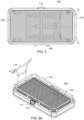
- Figure 5 is a top view of the cart 100 showing deck 122 upon which a load may be placed.
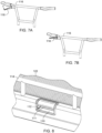
- Secure coupling lock release lever (or secure coupling lock release handle) assembly 110 is shown in Figure 1 and in more detail in Figure 8 .
- the secure coupling lock release lever assembly 110 is capable of providing a way for an operator to easily unlock a secure coupling lock assembly 202 from the operator side 102 of the cart 100 to demount the cart 100 from the vehicle.
- the secure coupling lock release lever assembly 110 is made up of a secure coupling lock release lever 111 and a secure coupling lock trim 112.
- the secure coupling lock release lever assembly 110 is connected to a secure coupling lock connecting rod 200 which in turn connects to and opens a secure coupling lock assembly 202 when activated which will be discussed in detail below.
- Figures 1-4 also show a brake mechanism of the cart 100.
- the brake mechanism may include independent caster wheel brakes, mechanical lock of wheel axle or friction on wheel itself, a multi-wheel pressure/friction bar, "deadman” brake with hand release to allow rolling, hand operated top or side wheel caliper brake and/or hand operated drum brake.
- FIG 6A is a perspective view of the top deck assembly 106 of the cart 100 and Figure 6B shows the top deck assembly with a load 120.
- Load 120 may be a wide variety of items such as coolers, groceries, tool chests, sports equipment, and the like. In terms of weight, in some embodiments, a load 120 may typically be up to and including approximately 226,8 kg (500 pounds). However, in alternative embodiments, the weight of the load 120 may be higher than 226,8 kg (500 pounds) depending on the strength of materials used in the cart 100 and/or the vehicle mounted hitch receiver 400.
- the cart 100 is shown in Figures 6A-6B with an optional guardrail 114 to keep load 120 in place during operation.
- FIG. 6B shows a typical load 120 which may be a fully enclosed cargo box or a cover over the deck 122.
- the guardrail 114 could drop down like a tailgate.
- the guardrail 114 could also have attachment devices for attaching accessories.
- FIGS 1 , 6A , 7A and 7B show handle 116 which may be used to push or pull the cart 100 during operation.
- the handle 116 can remain fixed in place after cart 100 is attached to a vehicle or, in an alternative embodiment, it could be folded, collapsed telescopically or otherwise stowed under the cart 100.
- the mount secure coupling 140 of the top deck assembly 102 will be positioned by the operator near the secure receiver 500 of the vehicle 404.
- the cart 100 is typically maneuvered into place for mounting through the operator pushing handle 116 until the mount secure coupling 140 is substantially aligned with and raised over the secure receiver 500 as shown in Figures 21A-22C which will be discussed in detail below.
- Handle 116 includes a hydraulic pump release lever 118 connected by a hydraulic release cable 117 to a hydraulic cylinder pump 150 located in the undercarriage assembly 107.
- the hydraulic pump release lever 118 lowers the mount secure coupling 140 onto secure receiver 500 by releasing pressure in the hydraulic cylinder pump 150 which controls the height of the undercarriage assembly 107 during coupling of the mount secure coupling 140 to the secure receiver 500.
- Figure 7A is a perspective view of the handle of the cart 100 before activation of hydraulic pump release lever 118. In Figure 7A , lever 118 is at rest with the pressure valve of the hydraulic cylinder pump 150 (shown in Figure 11 ) closed before activation.
- Figure 7B is a perspective view of the handle of the cart 100 after activation of lever 118.
- the operator squeezes the hydraulic pump release lever 118 to open the pressure valve releasing pressure in the hydraulic cylinder pump 150 and allow cart 100 to begin the mounting coupling sequence (or mount secure receiver coupling sequence) of the mount secure coupling 140 to the secure receiver 500 of the vehicle 404 (see Figures 21A-21B ).
- the hydraulic pump release lever 118 will typically be held in actuated position throughout the mounting coupling sequence process.
- top tines 144 and lower tines 145 of the mount secure coupling 140 descend into the top and bottom openings respectfully in the secure receiver 500 which is attached to the vehicle; the secure coupling lock assembly 202 engages and secures the cart 100; retraction of the undercarriage assembly 107; and the axle lock trigger releases stow axles 155 and folds wheels 108, 109 into an inward stowed position under the top deck assembly 106.
- Figure 8 is a detailed perspective view of the secure coupling lock release lever 111 of the secure coupling lock release lever assembly 110 shown in a locked position.
- the operator must manually pull the secure coupling release lever 111 out to release a secure coupling latch bolt 212 from the secure receiver 500 to allow the cart 100 to be lifted off the secure receiver 500 during the detaching of the cart 100 from the vehicle.
- the secure coupling lock latch bolt 212 will then reset for the next coupling of the cart 100 to the vehicle.
- FIG 9 is an exploded view of the components of the top deck assembly 106.
- Deck 122 is part of top deck assembly 106 to provide support for a load 120 placed on the cart 100.
- Deck assembly 106 and individual components; Guardrail 114, handle 116 and deck 122 may all be made of steel, aluminum, titanium, carbon fiber, or perhaps plastic (e.g., the deck surface). In alternative embodiments the handle 116 could be attached to the undercarriage 107.
- FIG 10 is a perspective exploded view of the mount secure coupling 140 which is attached to cart 100 and, as previously discussed, forms the cart side coupler which attaches to secure receiver 500 mounted on a vehicle 404.
- the mount secure coupling 140 is an assembly of components made up of a mount secure coupling plate 142 with mount secure coupling lower tines 145; a mount secure coupling top 143 with mount secure coupling top tines 144; and axle lock trigger 164.
- the mount secure coupling components can typically be made of strong, durable materials such as steel.
- the mount secure coupling top tines 144 may be self-aligning and self-seating into upper tine retention slots 508.
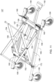
- FIG 11 is a perspective view of the undercarriage assembly 107 of the cart 100 without the top deck assembly 106 shown.
- Figure 12 is an exploded view of the parts making up the undercarriage assembly 107.
- the undercarriage assembly 107 includes mechanisms to achieve extension (or lift) and retraction (or lowering) of the top deck assembly 106.
- Hydraulic cylinder pump 150 operates a pair of lift scissors 152, 154 for retraction and extension to allow the top deck assembly 106 to change its height.
- the scissors are made up of a first scissor arm pair 152 and second scissor arm pair 154. Alternative embodiments could use double/multi scissor arm pairs.
- Figure 11 shows the cart 100 with the first scissor arm pair 152 and second scissor arm pair in full extension which would correspond to the top deck assembly 106 being at its highest height.
- a pair of axles capable of stowing the wheels 108, 109 i.e., "stow axles" 155 rotate to allow the wheels 108, 109 to be lifted up and turned inward until they are fully retracted (or hidden) during the process when the cart 100 is being attached to the vehicle.
- a pair of subframe tracks 156 arranged substantially in parallel allow small scissor arm pair wheels 157 connected to each of the first scissor arm pair 152 and second scissor arm pair 154 to move in a substantially horizontal direction as the scissor arm pairs 152, 154 and top deck assembly 106 move through different heights during extension and retraction.
- a pair of return springs 158 are configured to pull the scissor arm pairs 152, 154 back into a retraction position from the extension position upon mounting of the cart 100 onto the secure receiver 500.
- the return springs 158 can be simple coil, gas springs or another type of tension spring configuration, including internal within the hydraulic cylinder itself.
- a pair of axle rotation cams 160 are connected to and rotate with the stow axles 155 to assist with the wheels 108, 109 folding inward towards the top deck assembly 106.
- Hydraulic pump foot pedal 162 when activated by the operator puts more pressure into the hydraulic pump cylinder 150 to allow for control of the height of the top deck assembly 106.
- the operator can extend the scissor arm pairs 152, 154 and elevate the cart 100.
- the operator will provide force to pump the pedal 162 and raise the cart 100 so that the mount secure coupling 140 is located over the secure receiver 500 attached to the vehicle.
- the operator will then align the mount secure coupling 140 above the secure receiver 500 and over the upper tine retention slots 508. This allows for attachment of the mount secure coupling 140 with the secure receiver 500 as described in more detail below.
- the operator will pump the pedal 162 when the cart 100 is attached to the vehicle to extend the scissor arm pairs 152,154 and raise the top deck assembly 106 high enough to allow for detachment of the mount secure coupling 140 from the secure receiver 500 which also be described below in detail.
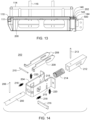
- Figure 13 is a cross-sectional view of the top deck assembly 106 of the cart 100 showing how the secure coupling lock lever assembly 110 is coupled through a secure coupling lock connecting rod 200 which runs the width of the cart 100 from the operator side 102 to the vehicle side 104 to control operation of a secure coupling lock assembly 202.
- the secure coupling lock assembly 202 is positioned as substantially centrally located on the long side of the mount secure coupling 140.
- Figure 14 is a perspective detailed exploded view of the components of the secure coupling lock assembly 202.
- the secure coupling lock connecting rod 200 slides in and out of a secure coupling lock bracket 204 as far as permitted by secure coupling lock connecting rod stop pin 206.
- secure coupling lock release 208 secure coupling lock release guide pin 210; secure coupling lock latch bolt 212; secure coupling lock latch bolt pin 213; secure coupling lock latch bolt spring 214; secure coupling locking catch slot 215; secure coupling locking catch 216; secure coupling release springs 218; and secure coupling catch springs 220.
- FIG 15 is a perspective of a vehicle mounted (or trailer mounted) hitch receiver 400 shown attached to a hitch receiver mounting arm & bracket 402 configured to connect to a vehicle 404.
- Figure 16 is a perspective view of the secure receiver 500 by itself and
- Figure 17 is a perspective view of a load bar adjustable extender 406. These elements 500, 406 in combination are shown in Figure 18 ready for attachment to the vehicle mounted hitch receiver 400.
- the load bar adjustable extender 406 can be used in an up or down orientation to adjust for varying centerline heights of the vehicle mounted hitch receiver 400.
- the load bar adjustable extender 406 is shown in a down position.
- Figure 18 illustrates the secure receiver 500 mounted on the load bar adjustable extender 406 (which is in an up position).
- the secure receiver 500 and load bar adjustable extender 406 could be one integrated piece.
- the secure receiver 500 is shown attached to the load bar adjustable extender 406, vehicle mounted hitch receiver 400 and a vehicle 404 in Figure 19 .
- the secure receiver 500 may act as a foot step when configured in a step shape. This secure receiver as a step configuration would be able to support the operator's weight and enable the operator to reach into the cargo area of the vehicle, the bed of a pickup, and/or the roof of the vehicle 404.
- the secure receiver 500 is a device to substantially align, safe-secure couple and lock a cart 100 to the hitch receiver 400 using mount secure coupling 140. As the cart 100 is mounted on the secure receiver 500 this mounting process will also allow for inward turning and clearance of the retracted wheels 108, 109 of the cart 100 from the ground.
- mount secure coupling 140 and Figure 16 secure receiver 500 has a lower flange 502 containing lower tine retention slots 504. These slots 504 receive corresponding mount secure coupling lower tines 145 of mount secure coupling 140 when the mount secure coupling 140 mates with the secure receiver 500.
- the secure coupling lock latch bolt 212 slides along the face of the secure receiver 500 and inserts itself into secure coupling lock opening 506.
- Upper tine retention slots 508 of secure receiver 500 receive corresponding top tines 144 of the mount secure coupling 140 upon coupling.
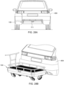
- Figures 20A-20C illustrate a side view and Figures 21A-21B illustrate a top view of the initial steps of coupling the cart 100 onto a vehicle 404 and turning the cart 100 into an attached carrier.
- the cart 100 is rolled up to the vehicle 404 and the operator will then elevate the cart 100 (see arrow 163 in Figure 20B ) by pumping the hydraulic pump foot pedal 162 connected to hydraulic cylinder pump 150 until the mount secure coupling 140 is raised to a height over the secure receiver 500.
- the operator then visually substantially aligns the mount secure coupling 140 and the mount secure coupling top tines 144 of the cart 100 with the upper tine retention slots 508 of the secure receiver 500 of the vehicle 404 as shown in Figures 21A-21B .
- FIG 22A shows a detailed side perspective view of a cutaway section of the cart 100 with the mount secure coupling 140 located above and substantially aligned with secure receiver 500.
- the mount secure coupling top tines 144 descend into the upper tine retention slots 508 as shown in Figure 22B .
- the inner radius of the top tines 144 come to rest on a radiused edge of the secure receiver 500.
- the mount secure coupling lower tines 145 slide into the lower tine retention slots 504 of the lower flange 502 of the secure receiver 500 as shown in Figure 22C .
- the top tines 144 along with the contact surfaces of the secure receiver 500 and mount secure coupling 140 support the payload weight of the cart 100 and its load 120.
- the lower tines 145 prevent the mount secure coupling 140 from hopping or bouncing out of the secure receiver 500, in particular, in a rotational or counter rotational direction.
- the secure coupling lock latch bolt 212 of the secure coupling lock assembly 202 of cart 100 is pressured (or projected) out by secure coupling lock latch bolt spring 214 to slide along the face of secure receiver 500 and into place inside the secure coupling lock opening 506 on the secure receiver 500 to secure the cart 100 from coming out of the secure receiver 500 in a substantially vertical shear direction. This allows for secure coupling locking and containment of the cart 100 on the secure receiver 500 against approximately all dynamic force directions.
- the structural integrity of the top deck assembly 106 and secure receiver are capable of self-supporting entirety of cart 100 and payload 120 weight.
- FIGs 23A-23D show the secure coupling locking system between the mount secure coupling 140 and the secure receiver 500 in a locking sequence in detail.
- secure coupling lock latch bolt 212 is in the unlocked latch bolt position in reset and ready to auto lock upon next descent of the top deck assembly 106 with mount secure coupling 140.
- the cart 100 is shown descending with mount secure coupling top tines 144 lowering into the upper tine retention slots 508 on top of secure receiver 500.
- secure coupling lock latch bolt 212 rides along the face of secure receiver 500 and pressurized by pushing back on Secure coupling lock latch bolt spring 213 (e.g., a compression spring) until reaching Secure coupling lock opening 506 in the secure receiver 500 where it inserts itself as shown in Figure 23D .
- secure coupling lock is fully “locked” with secure coupling lock latch bolt 212 inside secure coupling lock opening 506.
- Cart 100 is now securely mounted and locked to secure receiver 500.
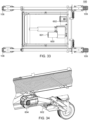
- FIGs 24A-24C show the elements of the cart 100 involved in the retraction of the undercarriage assembly 107, rotation of stow axles 155 and folding and stowing of wheels 108, 109.
- an axle lock trigger 164 which is housed behind mount secure coupling 140 and underneath top tines 144 is pushed back and rotated about the shoulder bolt that holds it within its bracket and also acts as an axis pivot (as shown by arrow 169 in Figure 24B ).
- This rotation action of the axle lock trigger 164 pulls the axle lock trigger cable 167 back (as shown by arrow 173 in Figure 24B ).
- axle lock trigger 167 is connected to both axle locking mechanisms 168 through axle lock 1-into-2 cable splitter 165 (see Figure 32 ) which retracts the duality of axle locking mechanism's axle lock release block 166 (see Figure 26F ) and allows the stow axles 155 to rotate in their respective axle bearing mounts 172.
- Figure 24C shows the axle rotation cams 160 operation of which will be discussed below.
- FIGs 25A-25E show operation of the elements of the undercarriage assembly 107 involved in the rotation of the stow axles 155 and the folding inward and stowing of wheels 108, 109.
- the axle lock trigger cable 167 attached to the axle lock trigger 164 pulls axle release block 166 (see Figure 26F ) back against a compression spring 174 as shown in Figure 25B (see arrow 175) which frees the axle rotation cam 160 to rotate (see arrow 177) as return springs 158 retract and axle rotation cams 160 contact top deck assembly 106.
- axle lock secondary cam 171 ( Figure 25A ) on the axle rotation cam 160 deflects the axle locking mechanism latch 170 out of the axle locking latch slot 176 in the axle lock release block 166 ( Figure 25B , 26F ) as axle rotation cam 160 rotates as shown in figure 25C .
- stow axles 155 are rotating the wheels 108, 109 inward and the axle locking mechanism latch 170 will come to rest on the top surface of axle lock release block 166 as shown in figure 25D where it will remain ready for re-latching when the wheels are re-deployed.
- stow axles 155 are shown fully rotated and wheels 108, 109 are folded in a stowed position where they are held in place by the retracted force of the return springs 158 and effectively positioning the axle locking mechanism 168 for redeploying the wheels.
- FIGS 26A-26F show further elements of the cart 100 involved in rotation of the stow axles 155 and wheels 108, 109 folding and stowage with an emphasis on the wheels stowage.
- wheel element 109 is shown in the foreground immediately adjacent to the axle locking mechanism 168 to represent how the axle locking mechanism "unlocks" and the axles freely rotate within the axle bearing mounts 172 to stow the wheels inward and upward under top deck assembly 106.
- the operator side wheels 109 are not shown but the front wheel pair 108 are shown indicating their dependency on the same activation and their rotation inward and upward.
- axle rotating cam 160 is also brought into contact with the underside of top deck assembly 106 by the force of return springs 158. It is dependent on the axle lock trigger 164 pulling axle lock trip cable 167 to release axle lock release block 166 (see Figures 25A-25E ) freeing stow axle 155 to rotate inside axle bearing mounts 172 (as shown by arrow 179).
- the axle rotation cam 160 stays in contact with top deck assembly 106 (as shown in Figures 26C-26E ) which rotates the axle 155 inside the axle bearing mounts 172 and folds the wheels 108, 109 up and inward.
- Figure 26B-26F all depict various stages of this stowing process from the axle rotation cam 160 contacting the underside of top deck assembly 106 and creating rotation of the stow axles 155 as contact continues along the top radius of axle rotation cams 160.
- FIGs 27A-27D show another view of the undercarriage assembly 107 retraction and wheel folding and stowing of the cart 100 during the mounting of the cart 100 onto the vehicle 404.
- the operator pulls hydraulic pump release lever 118 to activate hydraulic handle cable 117 attached to hydraulic cylinder pump 150 release valve.
- This action simultaneously lowers the top deck assembly 106 to allow the mount secure coupling 140 to descend on and mount (e.g., secure) to the secure receiver 500 and subsequently allowing for raising of the undercarriage assembly 107.
- mount secure coupling top tines 144 have bottomed onto the radiused edge of the secure receiver 500, the top deck assembly 106 is constrained and the remaining hydraulic cylinder pump 150 pressure is overcome by the return spring 158 tension force.
- the return springs 158 are shown externally connected to the undercarriage assembly 107 and lift it up (in alternative embodiments the return springs could be internal within the hydraulic cylinder), retracting the undercarriage assembly 107 underneath the top deck assembly 106. As the return springs 158 retract the undercarriage assembly 107 underneath the top deck assembly 106, and with the axle locking mechanism 168 retracted the stow axles 155 are free to rotate inside the axle bearings 172. Further, the bottom surface of the top deck assembly 106 contacts the axle rotation cam 160. This provides a force and path to rotate the stow axles 155 and connected wheels 108, 109 inward and underneath the top deck assembly 106.
- the undercarriage assembly 107 retracts and wheels 108, 109 are turned in and stored allowing proper clearance from the ground for operation of the vehicle 404.
- the cart 100 is safely and securely locked in place, the undercarriage assembly 107 including wheels 108, 109 are retracted and the operator is able to drive the vehicle 404 off.
- Figures 28A-28F and 29A-29E show the deployment and lock out of the wheels 108, 109 during uncoupling of the cart 100 from the vehicle 404.
- the operator will unlock the secure coupling release lever 111, pulling the secure coupling lock latch bolt 212 out of secure coupling lock opening 506 and allowing the cart 100 freedom to rise above the secure receiver 500.
- the operator will use the hydraulic pump foot pedal 162 to deploy the undercarriage assembly 107.
- the scissor arm pairs 152, 154 move along their subframe tracks 156 (as shown in Figures 11 and 12 ) and thereby extending the scissor arm pairs 152, 154 and effectively lowering undercarriage assembly 107 toward the ground.
- the axle rotation cam 160, the stow axle 155 and wheels 108, 109 will rotate until they reach an approximately ninety degree vertical position as shown in Figure 28D .
- the axle lock trigger 164 and axle locking mechanism 168 will reset to "locked” and prohibit the stow axles 155 from rotating when undercarriage assembly 107 including wheels 108, 109 are fully extended.
- the operator will continue to pump the hydraulic pump foot pedal 162 and the top deck assembly 106 will gradually lose contact with the secure receiver 500 as the mount secure coupling top tines 144 and mount secure coupling lower tines 145 of the mount secure coupling 140 rise above the secure receiver 500.
- the cart 100 is then elevated from the secure receiver 500 and released.
- the cart 100 is now able to be rolled away as shown in Figure 28E with the secure receiver 500 remaining on the vehicle 404 as shown in Figure 28F .
- FIGs 29A-29E show the locking system unlocking and retraction sequence in detail during uncoupling of the cart 100 from the vehicle 404.
- the secure coupling lock assembly 202 is fully “locked” with secure coupling lock latch bolt 212 inside secure coupling lock opening 506.
- secure coupling lock release lever 111 is "pulled” which causes secure coupling lock connecting rod 200 to extract the secure receiver latch bolt 212 from secure receiver 500 positioned above secure coupling locking catch 216. This allows the secure receiver catch springs 220 to pull the secure coupling locking catch 216 into a secure coupling locking catch slot 215 on the secure coupling lock latch bolt 212 and hold it in a retracted position as shown in Figure 29C .
- Figures 30A-30B are cross sectional views of cart 100 and show the elements of the mount secure coupling 140 involved in the stow axle 155 rotation and wheel 108, 109 unfolding and unstowing.
- Figure 30A shows axle lock trigger 164 inside the mount secure coupling 140 as the top deck assembly 106 rises.
- Figure 30B illustrates that as the cart 100 lifts off the secure receiver 500, the axle lock trigger 164 is pushed inward and a connected cable 167 is pulled (as shown by arrow 180) through a 1-into-2 cable splitter 165 (see Figure 32 ). This action releases the axle lock release block 166 (shown in Figures 31A-31D ) freeing each stow axles 155 to rotate inside axle bearing mounts 172.
- Figures 31A-31D illustrate a perspective view of deployment of the wheels 108, 109 during uncoupling of the cart 100 from the vehicle 404.
- the operator pulls secure coupling lock release lever 111 to allow cart 100 to be uncoupled from secure receiver 500.
- the operator then begins to pump the hydraulic foot pump pedal 162 and the hydraulic cylinder pump 150 will build pressure and force the return springs 158 and scissor arm pairs 152,154 to extend which will move the undercarriage assembly 107 downward toward the ground.
- axle rotation cams 160 to rotate about the bottom surface of top deck assembly 106 until fully losing contact with the top deck assembly 106 and allows gravity force of wheels 108, 109 and force of tension springs 174 ( Figure 31C ) to assist rotation of stow axles 155 (see arrow 181) inside axle bearing mounts 172 back to substantially vertical and engaging axle locking mechanism latch 170 into axle locking latch slot 176 on axle lock release block 166 of axle locking mechanism 168.
- Stow axles 155 are now locked ( Figure 31D ) with the wheels 108, 109 fully extended and ready to roll.
- FIG 32 is bottom view of the cart 100 showing the operation of the hydraulic pump release lever 118, hydraulic release cable 117 and axle lock trigger cable 167.
- the axle lock trigger cable 167 splits into first axle lock trigger cable split 167a and second axle lock trigger cable split 167b.
- Hydraulic release cable 117 connects hydraulic pump release lever 118 directly to a hydraulic pump 150 release valve to release pressure when pulled by operator.
- Axle lock trigger cable 167 connects axle lock trigger 164 to axle lock 1-to-2 cable splitter 165.
- axle lock trigger 164 deflects and pulls axle lock trigger cable 167.
- the axle lock trigger cable 167 splits into first axle lock trigger cable split 167a and second axle trigger cable split 167b which connect to axle locking mechanisms 168 to unlock stow axles 155.
- Figures 33-37 are views of an alternative embodiment of the undercarriage assembly.
- Figure 33 is top view of an alternative embodiment of the undercarriage assembly showing a linear actuator 600 and a battery receiver 602.
- Electro-mechanical actuators are similar to mechanical actuators (e.g., hydraulic cylinder pump 150) except that the source of power/leverage is replaced with an electric motor. Rotary motion of the motor is converted to linear displacement. The following is a description of the electro-mechanical linear actuator 600 used in this alternative embodiment.
- An electric motor is mechanically connected to rotate a lead screw.
- a lead screw has a continuous helical thread machined on its circumference running along the length (similar to the thread on a bolt). Threaded onto the lead screw is a lead nut or ball nut with corresponding helical threads.
- the nut is prevented from rotating with the lead screw (the nut interlocks with a non-rotating part of the actuator body). Therefore, when the lead screw is rotated, the nut will be driven along the threads.
- the direction of motion of the nut depends on the direction of rotation of the lead screw.
- By connecting linkages to the nut the motion can be converted to usable linear displacement.
- motors that can be used in linear actuator 600. These include DC brush, DC brushless, stepper, or in some cases, even induction motors.
- the linear actuator 600 will commonly have the motor as a separate cylinder attached to the side of the linear actuator 600, either parallel with the actuator or perpendicular to the actuator.
- a battery powered (DC) linear actuator 600 with the motor 601 attached to the side in parallel is used.
- the linear motion of the hydraulic actuator is replaced by the electro-mechanical linear actuator with internal lead screw.
- the DC motor 601 replaces the need for the foot pump 162, and since the linear motion is controlled in both extension and retraction the external return springs 158 can be eliminated in this alternative embodiment (i.e., the powered retraction cycle acts as a hydraulic cylinder would with an internal return spring).
- the axle locking mechanisms 168 in their entirety are eliminated as the linear actuator are controlled to specific stop points through limit or proximity switches.
- a limit or proximity switch replaces the axle lock trigger 164 to indicate coupling of cart 100 to secure receiver 500 is complete, and allow the full undercarriage assembly 107 retraction and stowing cycle for stow axles 155 and wheels 108, 109.
- Stow axles 155 are free to rotate within axle bearing mounts 172, but constrained rigid in any location including extended and vertical deployment by direct attachment to the linear actuator lead screw of the linear actuator 600.
- Figure 34 shows a battery 604 (e.g., 12 volts) in relation to the battery receiver 602.
- Figure 35 shows the first and second scissor arm pairs 152, 154 extended to lift the top deck assembly 106.
- Figure 36 shows the first and second scissor arm pairs 152, 154 retracted to lower the top deck assembly.
- Figure 37 is an elongated view cutaway with battery 604 shown.
- FIGs 38A-38D show the depression of switch 606 to lower first and second scissor arm pairs 152, 154 for the mount secure coupling 140 to dock into secure receiver 500.
- a toggle or rocker switch 606 e.g., double pole, double throw rocker switches with momentary on
- Figure 38B the mount secure coupling 140 is substantially aligned and prepared to descend onto the secure receiver 500.
- Figure 38C switch 606 is depressed to descend the mount secure coupling 140 and retract the undercarriage assembly 107 into the top deck assembly.
- a proximity or limit switch would sense/indicate or make contact (indicating safe to continue) to allow the linear actuator 600 to continue to travel to full retraction.
- Figures 39A to 39C depict the continuation of the retraction of the undercarriage assembly 107 by power of the linear actuator 600 as it travels to home position.
- the stow axles 155 freely rotating in their axle bearing mounts 172 and rotate when the axle rotation cam 160 contacts the underside of the top deck assembly (as like the first embodiment) folding the wheels 108, 109 up and in.
- Figures 40A-40D shows depression of toggle switch to deploy undercarriage assembly 107 and wheels 108, 109.
- Figure 40A shows the switch 606 in a neutral position with the cart 100 mounted on the vehicle 404 as shown in Figure 40B .
- the switch 606 has been depressed and when energizing the switch in this direction the linear actuator 600 shaft will extend pushing the scissor pairs 152, 154 in the tracks and extending the undercarriage assembly 107 down.
- the stow axles 155 will rotate down till the wheels 108, 109 are vertical and ready to contact the road surface.
- the switch will continue to extend the linear actuator 600 shaft and scissor arm pairs 152, 154 until the top deck assembly 106 ascends above the secure receiver 500 and the cart 100 can be rolled away.
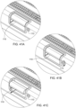
- Figures 41A-41C show another alternative embodiment of the cart 100 with the secure coupling lock release lever assembly 110 having an associated key lock 113 to prevent the secure coupling lock release lever 111 from leaving a locked position when the key lock 113 is also locked. This will provide security to prevent someone from taking the cart 100 without permission.
- the secure coupling lock release lever assembly 110 shown in Figure 41A is key locked and secure coupling lock release lever assembly 110 locked.
- Figure 41B is key unlocked and secure coupling lock release lever assembly 110 unlocked.
- Figure 41C is key unlocked and secure coupling lock release lever assembly 110 unlocked which would allow cart 100 to be removed from secure receiver 500.
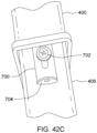
- FIGs 42A-42C shows an alternative embodiment of the secure receiver 500 with a sliding shim 700 attached directly to the load bar extender 406 (see Figures 17 and 18 ).
- the sliding or rotational shim is attached to the load bar extender 406 through a fastener mechanism 702 such as a screw (as shown) or a rivet, or similar.
- Figure 42B is a side view of the shim 700 mounted on the load bar extender 406. Sliding and rotating shim 700 adds rigidity and prevents wobbling of the secure receiver 500 and therefore the cart 100 when it is attached to a vehicle 404.
- Sliding and rotating shim 700 is capable of sliding back and forth along shim slot 703 or rotating about its fastener to conveniently insert or remove to and from a vehicle mounted hitch receiver 400 (see Figure 15 ) to take up tolerance gap between the mating parts and minimize unwanted play or wobble.
- Shim grip 704 allows for easy hand location and moving of the sliding and rotating shim 700 into the gap between the mating surfaces of the load bar extender 406 and the hitch receiver 400.
- Figure 42C is a bottom view of sliding and rotating shim 700 inserted between the load bar extender 406 and hitch receiver 400.
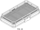
- FIG 43 shows another alternative embodiment of the cart 100 which operates through manual lift on and off of the cart 100 and mount secure coupling 140 to the secure receiver 500.
- the coupling of the mount secure coupling 140 to the secure receiver 500 is accomplished in the same way as described above but without the assistance of the hydraulic cylinder pump or linear actuator.
- the top deck assembly 106 is manually maneuvered into place by an operator (or a plurality of operators depending on the weight of the load).
- This alternative embodiment of the cart 100 is lower cost and lighter weight, and may or may not have wheels
- Figure 44A-44E show another alternative embodiment of the cart with manual wheel (108, 109) folding.
- Fold down handle 800 is capable of being unlatched and dropped down approximately ninety degrees until in line with a pair of nesting tubes 802. Pins attached to the fold down handle 800 and protruding through nesting tube 802 will travel along a spiral barrel cam mechanism 804 cut into the wheel mounts. As the fold down handle 800 is pushed in, the travel of the pins through the spiral groove of the barrel cam will cause the nesting tube 802 and attached wheel mounts to rotate thereby causing the wheels to fold up.
- Arrow 806 in Figure 44B shows fold down and push in fold down handle 800 into nesting tubes 802.
- Figure 44C is a perspective view.
- Figure 44D is a top view of undercarriage assembly showing barrel cams and nesting tubes.
- Figure 44E shows fold down handle pushed in and wheels 108, 109 folded up.
- Figures 45A-45C illustrate an alternative embodiment of the cart 100 showing the top deck assembly 106 having a bicycle deck 123 configured to carry a load of bicycles.
- This embodiment has the ability to mount and/or attach many accessories including cargo boxes, bike racks, ski containers, and the like. Attachment mechanisms would include thumb screws, lever locks, quick release latches and the like.
- Figures 45B and 45C show a universal dock surface with attachment mechanisms like grooves, t-slots, contours. Also, along perimeter surface of frame of cart 100. Combinations of accessories possible such as boxes, containers and racks, baskets, and the like.
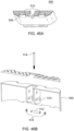
- Figures 46A to 46B show an alternative embodiment of the secure receiver 500 having a different configurations.
- a round bar element 510 at upper tine retention slots 508 functions to improve self alignment of mount secure coupling top tines 144 when coupling (i.e., upon descent of top deck assembly 106). This also results in reduction of friction and better engagement seating for the mount secure coupling 140 upon mounting of the cart 100.
- Figure 46B illustrates a leveling pin 512 with self contained leveling adjustment roller 512 and set screw 514. Set screw 514 is threaded into leveling adjustment roller 512 which is retained in angled adjustment slot 515 by retention snap rings 516 or similar shoulder bolt and cotter pin.
- the set screw 514 can be tightened which will draw the leveling adjustment roller 512 upward following the path of the angled slot 151 and along the face of the load bar to take up tolerance between the fasteners and the fastener holes in both the secure receiver 500 and the load bar extender 406 to effectively rotate the secure receiver 500 to level and plumb.
- FIG 47A is a flowchart outlining the method of mounting the cart 100 to a vehicle.
- the cart 100 is rolled up to the vehicle.
- the mount secure coupling 140 is aligned directly above the secure receiver 500.
- the mount secure coupling 140 is lowered onto the secure receiver 500 by the hydraulic cylinder pump 150, linear actuator 600 or manually by the operator (depending on the embodiment).
- the undercarriage assembly 107 is retracted along with the wheels 108, 108 which are stowed under the top deck assembly 106.
- the mount secure coupling 140 is locked to the secure receiver 500.
- the vehicle drives off with the cart 100 acting as a carrier.
- Figure 47B is a flowchart outlining the method of demounting the cart 100 from a vehicle.
- step 912 the secure coupling lock release lever assembly 110 is unlocked by the operator.
- step 914 the undercarriage assembly 107 is extended and the wheels 108, 109 are unlocked.
- step 916 the mount secure coupling 140 is raised above the secure receiver 500 by the hydraulic cylinder pump 150, linear actuator 600 or manually by the operator (again depending on the embodiment).
- step 918 the cart is rolled way by the operator.
- Loads 120 carried by the cart 100 may include grills, coolers, tool chests, workbench, and the like and also serve in the capacity of a lift table and work surface.
Landscapes
- Engineering & Computer Science (AREA)
- Mechanical Engineering (AREA)
- Chemical & Material Sciences (AREA)
- Combustion & Propulsion (AREA)
- Transportation (AREA)
- Handcart (AREA)
Description
- This application claims the benefit of
U.S. Provisional Patent Application Serial No. 62/344,436, filed June 2, 2016 - The present invention relates to carts and, more particularly, it relates to mechanisms for attaching a cart to a vehicle.
- Several types of collapsible and foldable carts for transporting articles or goods have been utilized in the past. Generally, these types of foldable carts are used by home owners for transporting of groceries, packages, luggage, duffle bags, ski equipment, sports gear, musical equipment, and the like. Some of these may have a capability to work at multiple heights as well. These foldable, and/or adjustable height carts are also implemented for commercial and light industry usage in the transporting of in process goods, finished products, tools and construction equipment and the like.
US 2009/0232633 A1 discloses a cart with an upper portion, a lower portion, wheels, and steering suitable for both maneuvering while in a store, and on more rugged terrain. The cart may be carried suspended from a trailer hitch behind a motor vehicle. The cart has a vertical positioner to raise and lower the upper portion and lower portion relative to the other. The cart may be used as an off-road utility trailer, being towed by a vehicle.
FromUS 7,249,771 B1 , a transportable utility carrier apparatus for coupling to a transport vehicle is known, including an upper frame, a recessed platform connected to the upper frame, a wheeled base, a lift system interposed between the base and the upper frame for moving the wheeled base relative to the platform between a transport position and a freestanding position, a square hitch tube connected to the upper frame, and a rollered receiver hitch mountable to the transport vehicle. The wheels are spaced from the ground in the transport position. The square hitch tube is receivable within the rollered receiver hitch and the rollered receiver hitch eases insertion of the square hitch tube there into to prevent binding on unleveled ground.
WO 2016/000042 A1 discloses a mobile cargo carrier for mounting onto the rear of a vehicle, the mobile cargo carrier including a storage container having a wheel arrangement, suspension means for removably connecting the storage container to a rear of a vehicle, the suspension means operable to suspend the storage container from the rear of the vehicle above the road surface and jacking means for vertically displacing the storage container relative to the wheel arrangement. - Aspects of the disclosure include a cart and mount secure coupling and receiver system comprising: a cart including: a top deck assembly having a carrying portion, a mount secure coupling and a Secure coupling lock assembly; an undercarriage assembly capable of supporting and adjusting the height of the top deck assembly so that the mount secure coupling is capable of being attached to a secure receiver by the engagement of both the mount secure coupling and the Secure coupling lock assembly.
- Further aspects of the disclosure include a method of coupling a cart to a secure receiver: the cart is placed in position with a mount secure coupling mounted on a top deck assembly of the cart substantially aligned with the secure receiver; a hydraulic pump foot pedal coupled to a hydraulic cylinder pump in an undercarriage assembly of the cart receives pumps from a operator to elevate the mount secure coupling above the secure receiver; and a hydraulic release lever is activated to release pressure in the hydraulic cylinder pump to lower the mount secure coupling onto the secure receiver and cause the undercarriage assembly to rise.
- Further aspects of the disclosure include a secure receiver comprising: at least one retention tine slot capable of receiving a corresponding at least one mount secure coupling top tine; at least one lower tine reception slot capable of receiving a corresponding at least one mount secure coupling lower tine; and an opening capable of receiving a latch bolt.
- Further aspects of the disclosure include a secure receiver comprising: a plurality of retention tine slots capable of receiving a corresponding plurality of mount secure coupling top tines; a plurality of lower tine reception slots capable of receiving a corresponding plurality of mount secure coupling lower tines; and at least one opening capable of receiving a latch bolt. The plurality of mount secure coupling top tines may be self-aligning and self-seating into upper tine retention slots of the secure receiver.
- The problems described above are solved according to the invention by the features of the independent claims. Preferred embodiments of the invention are defined in the dependent claims. Aspects of the embodiments of this invention are illustrated by way of example. While various details of one or more techniques are described herein, other techniques are also possible. In some instances, well-known structures and devices are shown in block diagram form in order to facilitate describing various techniques. A further understanding of the nature and advantages of examples provided by the disclosure can be realized by reference to the remaining portions of the specification and the drawings, wherein like reference numerals are used throughout several drawings to refer to similar components.
-
Figure 1 is a perspective view of thecart 100 from the side facing an operator when the cart is being mounted onto a vehicle (i.e., the "operator side" 102). Thecart 100 is shown in upright mode with undercarriage assembly scissors extended and wheels locked out. -
Figure 2 is a perspective view of thecart 100 from the side facing the vehicle during mounting (i.e., the "vehicle side" 104). -
Figure 3 is an elongated (or lengthwise) view of thecart 100 from thevehicle side 104. -
Figure 4 is a side view of thecart 100 from the handle side. -
Figure 5 is a top view of thecart 100 showingdeck 122 upon which a load may be placed. -
Figure 6A is a perspective view of a top deck assembly of thecart 100 andFigure 6B shows atypical load 120 which may be a fully enclosed cargo box or a cover over thedeck 122. -
Figure 7A is a perspective view of the handle of thecart 100 before activation of hydraulicpump release lever 118 andFigure 7B is a perspective view of the handle of thecart 100 after activation oflever 118. -
Figure 8 is a detailed perspective view of the secure couplinglock release lever 111 of the secure coupling lockrelease lever assembly 110 shown in a locked position. -
Figure 9 is an exploded view of the components of the top deck assembly. -
Figure 10 is a perspective view of the mountsecure coupling 140 assembly. -
Figure 11 is a perspective view of theundercarriage assembly 107 of thecart 100 without thetop deck assembly 106 shown. -
Figure 12 is an exploded view of the parts making up the undercarriage assembly of thecart 100. -
Figure 13 is a cross-sectional view of thetop deck assembly 106 of thecart 100 showing how the secure couplinglock lever assembly 110 is coupled through a secure coupling lock connecting rod which runs the width of thecart 100 from theoperator side 102 to thevehicle side 104 to control operation of a securecoupling lock assembly 202. -
Figure 14 is a perspective detailed exploded view of the components of a securecoupling lock assembly 202. -
Figure 15 is a perspective of a vehicle mounted (or trailer mounted)hitch receiver 400 shown attached to a hitch receiver mounting arm &bracket 402 configured to connect to a vehicle. -
Figure 16 is a perspective view of thesecure receiver 500. -
Figure 17 is a perspective view of a standard load baradjustable extender 406. -
Figure 18 is a perspective view of asecure receiver 500 assembled on a load baradjustable extender 406. -
Figure 19 is a perspective view of thesecure receiver 500 assembled to the load baradjustable extender 406 on the back of avehicle 404. -
Figures 20A-20C illustrate a side view andFigures 21A-21 B illustrate a top view of the initial steps of coupling thecart 100 onto avehicle 404 and turning thecart 100 into an attached carrier. -
Figures 22A-22C show a detailed perspective view of the mountsecure coupling 140 mounting onto thesecure receiver 500. -
Figures 23A-23D show a side view of the mountsecure coupling 140 mounting onto thesecure receiver 500 emphasizing the securecoupling lock assembly 202 locking sequence in detail. -
Figures 24A-24C show the elements of thecart 100 involved in theundercarriage assembly 107 retraction,stow axles 155 rotation andwheel -
Figures 25A-25E show the elements of the undercarriage assembly involved in thestow axle 155 locking mechanism, rotation andwheel -
Figures 26A-26F show the elements of thecart 100 involved in thestow axle 155 rotation andwheel -
Figures 27A-27D show another view of theundercarriage assembly 107 retraction and wheel folding and stowing of thecart 100 during the mounting of thecart 100 onto thevehicle 404. -
Figures 28A-28F show the deployment and lock out of thewheels cart 100 from thevehicle 404. -
Figures 29A-29E show the secure coupling lock assembly unlocking, retraction, and resetting sequence in detail. -
Figures 30A-30B are cross sectional views ofcart 100 and show the elements of the mountsecure coupling 140 andsecure receiver 500 involved in thestow axle 155 rotation andwheel -
Figures 31A-31D illustrate a perspective view of deployment of thewheels cart 100 from thevehicle 404. -
Figure 32 is bottom view of thecart 100 showing the operation of the hydraulicpump release lever 118,hydraulic handle cable 117 and axlelock trigger cable 167. -
Figures 33-37 are view of an alternative embodiment of the undercarriage assembly with alinear actuator 600 powering the extension and retraction of the undercarriage assembly 107 (instead of the hydraulic cylinder pump 150). -
Figures 38A-38D show the depression ofswitch 606 to lower first and secondscissor arm pairs secure coupling 140 to dock intosecure receiver 500. -
Figures 39A to 39C depict the continuation of the retraction of theundercarriage assembly 107 by power of thelinear actuator 600 and folding of the wheels. -
Figures 40A-40D shows depression of toggle switch to deployundercarriage assembly 107 andwheels -
Figures 41A-41C show another alternative embodiment of thecart 100 with the secure coupling lockrelease lever assembly 110 having an associatedkey lock 113 to prevent the secure couplinglock release lever 111 from leaving a locked position when thekey lock 113 is also locked. -
Figures 42A-42C shows an alternative embodiment of thesecure receiver 500 with a slidingshim 700 attached directly to theload bar extender 406. -
Figure 43 shows another alternative embodiment of thecart 100 which operates through manual lift on and off of thecart 100 and mountsecure coupling 140 to thesecure receiver 500. -
Figure 44A-44E show an alternative embodiment of the cart with manual wheel folding. -
Figures 45A-45C illustrate an alternative embodiment of thecart 100 showing thetop deck assembly 106 having a bicycle deck 123 configured to carry a load of bicycles. -
Figures 46A to 46B show an alternative embodiment of thesecure receiver 500 having a different configurations. -
Figure 47A is a flowchart outlining the method of mounting thecart 100 to a vehicle andFigure 47B is a flowchart outlining the method of demounting thecart 100 from a vehicle. - Typical carts permit the transport of goods up and down walkways, steep hills, across dirt trails, and the like, without causing damage to walkway surfaces, such as linoleum, tile, wood, or carpeting. However, conventional carts which have been used in the past lack convenience and versatility. For example, they require lifting of materials and/or the cart itself which limits transportability, lacks maneuverability and handling convenience for the various uses to which such carts are put in warehouses and retail establishments. The embodiments described herein address a gap in currently available material handling devices. Although there are many carts available to move materials from place to place, virtually all unpowered devices require manual "lifting" of either the payload (i.e., the carried materials, tools, resources, etc.), the cart, or both at multiple steps of the transportation process. For example, grocery shopping requires loading and unloading of the shopping cart multiple times to get the groceries/merchandise from store shelf to the kitchen pantry in one's house. Many similar examples exist in industrial manufacturing, assembly, and logistics. Examples also exist in commercial construction and professional trades in movement of tools, materials and other resources from point of supply (store/warehouse) to job site, workbench and other points of use. For leisure, sporting events, or adventure travel the same issues exist in attempting to move necessary gear from place to place.
-
Figures 1 through 6B show a mobile, height adjustable and vehicleattachable cart 100 and itsassociate coupling mechanisms secure coupling 140 withsecure receiver 500 together form a Mount Secure Coupling & Secure Receiver System for mounting and demounting thecart 100 on a vehicle.Cart 100 is capable of rolling and is steerable on retractable and stowable wheels.Figure 1 is a perspective view ofmobile cart 100 from the side facing the operator when the cart is being mounted onto a vehicle (the "operator side" 102).Figure 2 is a perspective view of thecart 100 from the side facing the vehicle during mounting (the "vehicle side" 104). Thecart 100 has atop deck assembly 106 and anundercarriage assembly 107 each of which are made up of numerous component parts.Figure 3 is an elongated view of thecart 100 from thevehicle side 104.Figure 4 is a side view of thecart 100 from thehandle 116 side. InFigures 1-4 thecart 100 is shown in upright mode with supporting scissor arm pairs 152, 154 of theundercarriage assembly 107 extended andwheels secure coupling 140 on thevehicle side 104 of thecart 100 allows thecart 100 to mate to asecure receiver 500 mounted (typically) on the rear of a vehicle which is configured to receive the mountsecure coupling 140. (Thesecure receiver 500 is also a "universal coupler" or "hitch coupler" usable on any vehicle with a tow hitch which emphasizes its flexibility). The foot step configuration of thesecure receiver 500 is an alternative embodiment in which the secure receiver functions as a flat surface step allowing the operator to stand on it.Figure 5 is a top view of thecart 100 showingdeck 122 upon which a load may be placed. - The
undercarriage assembly 107 includes a pair of front (or first)wheels 108 which may be rigid and a pair of rear (or second)wheels 109 which may swivel (e.g., caster wheels able to turn 360 degrees). Both sets ofwheels undercarriage assembly 107 to provide clearance from the ground for thecart 100 when thecart 100 is mounted on the back of a vehicle. As the vehicle travels, thecart 100 will be high enough not to bottom on a highway or catch objects underneath that are in the path of the vehicle (i.e., typically after mounting of the cart on the vehicle thewheels assembly 110 is shown inFigure 1 and in more detail inFigure 8 . The secure coupling lockrelease lever assembly 110 is capable of providing a way for an operator to easily unlock a securecoupling lock assembly 202 from theoperator side 102 of thecart 100 to demount thecart 100 from the vehicle. The secure coupling lockrelease lever assembly 110 is made up of a secure couplinglock release lever 111 and a securecoupling lock trim 112. The secure coupling lockrelease lever assembly 110 is connected to a secure couplinglock connecting rod 200 which in turn connects to and opens a securecoupling lock assembly 202 when activated which will be discussed in detail below. -
Figures 1-4 also show a brake mechanism of thecart 100. The brake mechanism may include independent caster wheel brakes, mechanical lock of wheel axle or friction on wheel itself, a multi-wheel pressure/friction bar, "deadman" brake with hand release to allow rolling, hand operated top or side wheel caliper brake and/or hand operated drum brake. -
Figure 6A is a perspective view of thetop deck assembly 106 of thecart 100 andFigure 6B shows the top deck assembly with aload 120.Load 120 may be a wide variety of items such as coolers, groceries, tool chests, sports equipment, and the like. In terms of weight, in some embodiments, aload 120 may typically be up to and including approximately 226,8 kg (500 pounds). However, in alternative embodiments, the weight of theload 120 may be higher than 226,8 kg (500 pounds) depending on the strength of materials used in thecart 100 and/or the vehicle mountedhitch receiver 400. Thecart 100 is shown inFigures 6A-6B with anoptional guardrail 114 to keepload 120 in place during operation. In alternative embodiments without theguardrail 114, larger loads may be placed on thedeck 122 of thetop deck assembly 106 without the hindrance of theguardrail 114 and secured by other means.Figure 6B shows atypical load 120 which may be a fully enclosed cargo box or a cover over thedeck 122. In alternative embodiments, theguardrail 114 could drop down like a tailgate. Theguardrail 114 could also have attachment devices for attaching accessories. -
Figures 1 ,6A ,7A and 7B show handle 116 which may be used to push or pull thecart 100 during operation. Thehandle 116 can remain fixed in place aftercart 100 is attached to a vehicle or, in an alternative embodiment, it could be folded, collapsed telescopically or otherwise stowed under thecart 100. During a mounting operation of thecart 100 to avehicle 404, the mountsecure coupling 140 of thetop deck assembly 102 will be positioned by the operator near thesecure receiver 500 of thevehicle 404. Thecart 100 is typically maneuvered into place for mounting through theoperator pushing handle 116 until the mountsecure coupling 140 is substantially aligned with and raised over thesecure receiver 500 as shown inFigures 21A-22C which will be discussed in detail below. Handle 116 includes a hydraulicpump release lever 118 connected by ahydraulic release cable 117 to ahydraulic cylinder pump 150 located in theundercarriage assembly 107. When activated, the hydraulicpump release lever 118 lowers the mountsecure coupling 140 ontosecure receiver 500 by releasing pressure in thehydraulic cylinder pump 150 which controls the height of theundercarriage assembly 107 during coupling of the mountsecure coupling 140 to thesecure receiver 500.Figure 7A is a perspective view of the handle of thecart 100 before activation of hydraulicpump release lever 118. InFigure 7A ,lever 118 is at rest with the pressure valve of the hydraulic cylinder pump 150 (shown inFigure 11 ) closed before activation.Figure 7B is a perspective view of the handle of thecart 100 after activation oflever 118. InFigure 7B withlever 118 activated, the pressure valve ofhydraulic cylinder pump 150 is opened. Hydraulicpump release lever 118 may be used to lower the top deck assembly 106 (also described in detail below) while hydraulicpump foot pedal 162 may be pumped by the operator to raise thetop deck assembly 106. (In an alternative embodiment, instead of ahydraulic cylinder pump 150 an electric motor and linear actuator may be used to raise and lower thetop deck assembly 106 which will be discussed in connection withFigures 34 -41D). Once thecart 100 is aligned above thesecure receiver 500, the operator squeezes the hydraulicpump release lever 118 to open the pressure valve releasing pressure in thehydraulic cylinder pump 150 and allowcart 100 to begin the mounting coupling sequence (or mount secure receiver coupling sequence) of the mountsecure coupling 140 to thesecure receiver 500 of the vehicle 404 (seeFigures 21A-21B ). The hydraulicpump release lever 118 will typically be held in actuated position throughout the mounting coupling sequence process. This allows a sequence of events to unfold including the following:top tines 144 andlower tines 145 of the mountsecure coupling 140 descend into the top and bottom openings respectfully in thesecure receiver 500 which is attached to the vehicle; the securecoupling lock assembly 202 engages and secures thecart 100; retraction of theundercarriage assembly 107; and the axle lock trigger releasesstow axles 155 and foldswheels top deck assembly 106. -
Figure 8 is a detailed perspective view of the secure couplinglock release lever 111 of the secure coupling lockrelease lever assembly 110 shown in a locked position. As a failsafe measure the operator must manually pull the securecoupling release lever 111 out to release a securecoupling latch bolt 212 from thesecure receiver 500 to allow thecart 100 to be lifted off thesecure receiver 500 during the detaching of thecart 100 from the vehicle. The secure couplinglock latch bolt 212 will then reset for the next coupling of thecart 100 to the vehicle. -
Figure 9 is an exploded view of the components of thetop deck assembly 106.Deck 122 is part oftop deck assembly 106 to provide support for aload 120 placed on thecart 100.Deck assembly 106 and individual components;Guardrail 114, handle 116 anddeck 122 may all be made of steel, aluminum, titanium, carbon fiber, or perhaps plastic (e.g., the deck surface). In alternative embodiments thehandle 116 could be attached to theundercarriage 107. -
Figure 10 is a perspective exploded view of the mountsecure coupling 140 which is attached to cart 100 and, as previously discussed, forms the cart side coupler which attaches to securereceiver 500 mounted on avehicle 404. The mountsecure coupling 140 is an assembly of components made up of a mountsecure coupling plate 142 with mount secure couplinglower tines 145; a mountsecure coupling top 143 with mount secure couplingtop tines 144; andaxle lock trigger 164. The mount secure coupling components can typically be made of strong, durable materials such as steel. The mount secure couplingtop tines 144 may be self-aligning and self-seating into uppertine retention slots 508. -
Figure 11 is a perspective view of theundercarriage assembly 107 of thecart 100 without thetop deck assembly 106 shown.Figure 12 is an exploded view of the parts making up theundercarriage assembly 107. Theundercarriage assembly 107 includes mechanisms to achieve extension (or lift) and retraction (or lowering) of thetop deck assembly 106.Hydraulic cylinder pump 150 operates a pair oflift scissors top deck assembly 106 to change its height. The scissors are made up of a firstscissor arm pair 152 and secondscissor arm pair 154. Alternative embodiments could use double/multi scissor arm pairs.Figure 11 shows thecart 100 with the firstscissor arm pair 152 and second scissor arm pair in full extension which would correspond to thetop deck assembly 106 being at its highest height. As thetop deck assembly 106 descends and mountsecure coupling 140 mounts ontosecure receiver 500 through mechanisms discussed below, a pair of axles capable of stowing thewheels 108, 109 (i.e., "stow axles") 155 rotate to allow thewheels cart 100 is being attached to the vehicle. A pair of subframe tracks 156 arranged substantially in parallel allow small scissorarm pair wheels 157 connected to each of the firstscissor arm pair 152 and secondscissor arm pair 154 to move in a substantially horizontal direction as the scissor arm pairs 152, 154 andtop deck assembly 106 move through different heights during extension and retraction. A pair of return springs 158 are configured to pull the scissor arm pairs 152, 154 back into a retraction position from the extension position upon mounting of thecart 100 onto thesecure receiver 500. The return springs 158 can be simple coil, gas springs or another type of tension spring configuration, including internal within the hydraulic cylinder itself. A pair ofaxle rotation cams 160 are connected to and rotate with thestow axles 155 to assist with thewheels top deck assembly 106. Hydraulicpump foot pedal 162 when activated by the operator puts more pressure into thehydraulic pump cylinder 150 to allow for control of the height of thetop deck assembly 106. In particular, during attachment and detachment of thecart 100 to and from the vehicle through the use of the operator's foot in a pumping action the operator can extend the scissor arm pairs 152, 154 and elevate thecart 100. As the operator approaches the back of the vehicle with thecart 100, the operator will provide force to pump thepedal 162 and raise thecart 100 so that the mountsecure coupling 140 is located over thesecure receiver 500 attached to the vehicle. The operator will then align the mountsecure coupling 140 above thesecure receiver 500 and over the uppertine retention slots 508. This allows for attachment of the mountsecure coupling 140 with thesecure receiver 500 as described in more detail below. Correspondingly, the operator will pump thepedal 162 when thecart 100 is attached to the vehicle to extend the scissor arm pairs 152,154 and raise thetop deck assembly 106 high enough to allow for detachment of the mountsecure coupling 140 from thesecure receiver 500 which also be described below in detail. -
Figure 13 is a cross-sectional view of thetop deck assembly 106 of thecart 100 showing how the secure couplinglock lever assembly 110 is coupled through a secure couplinglock connecting rod 200 which runs the width of thecart 100 from theoperator side 102 to thevehicle side 104 to control operation of a securecoupling lock assembly 202. The securecoupling lock assembly 202 is positioned as substantially centrally located on the long side of the mountsecure coupling 140.Figure 14 is a perspective detailed exploded view of the components of the securecoupling lock assembly 202. During operation, the secure couplinglock connecting rod 200 slides in and out of a securecoupling lock bracket 204 as far as permitted by secure coupling lock connectingrod stop pin 206. As a conscious failsafe measure the operator will need to manually pull the secure couplinglock release lever 111 out to retract thepassive latch bolt 212 from thesecure receiver 500. Thepassive latch bolt 212 is held back by the secure coupling locking catch (or sear) 216 to allow thecart 100 to be lifted off thesecure receiver 500. Further components which make up the securecoupling lock assembly 202 and the functions of which will be described further below include the following: securecoupling lock release 208; secure coupling lockrelease guide pin 210; secure couplinglock latch bolt 212; secure coupling locklatch bolt pin 213; secure coupling locklatch bolt spring 214; secure coupling lockingcatch slot 215; securecoupling locking catch 216; secure coupling release springs 218; and secure coupling catch springs 220. -
Figure 15 is a perspective of a vehicle mounted (or trailer mounted)hitch receiver 400 shown attached to a hitch receiver mounting arm &bracket 402 configured to connect to avehicle 404.Figure 16 is a perspective view of thesecure receiver 500 by itself andFigure 17 is a perspective view of a load baradjustable extender 406. Theseelements Figure 18 ready for attachment to the vehicle mountedhitch receiver 400. The load baradjustable extender 406 can be used in an up or down orientation to adjust for varying centerline heights of the vehicle mountedhitch receiver 400. InFigure 17 , the load baradjustable extender 406 is shown in a down position.Figure 18 illustrates thesecure receiver 500 mounted on the load bar adjustable extender 406 (which is in an up position). In an alternative embodiment, thesecure receiver 500 and load baradjustable extender 406 could be one integrated piece. Thesecure receiver 500 is shown attached to the load baradjustable extender 406, vehicle mountedhitch receiver 400 and avehicle 404 inFigure 19 . In addition to acting as an attachment mechanism for the mountsecure coupling 140 ofcart 100, thesecure receiver 500 may act as a foot step when configured in a step shape. This secure receiver as a step configuration would be able to support the operator's weight and enable the operator to reach into the cargo area of the vehicle, the bed of a pickup, and/or the roof of thevehicle 404. - The
secure receiver 500 is a device to substantially align, safe-secure couple and lock acart 100 to thehitch receiver 400 using mountsecure coupling 140. As thecart 100 is mounted on thesecure receiver 500 this mounting process will also allow for inward turning and clearance of the retractedwheels cart 100 from the ground. Referring to bothFigure 10 with regard to the mountsecure coupling 140 andFigure 16 secure receiver 500, has alower flange 502 containing lowertine retention slots 504. Theseslots 504 receive corresponding mount secure couplinglower tines 145 of mountsecure coupling 140 when the mountsecure coupling 140 mates with thesecure receiver 500. During coupling of thecart 100 to the vehicle, the secure couplinglock latch bolt 212 slides along the face of thesecure receiver 500 and inserts itself into securecoupling lock opening 506. Uppertine retention slots 508 ofsecure receiver 500 receive correspondingtop tines 144 of the mountsecure coupling 140 upon coupling. Collectively, inserting the mount secure couplingtop tines 144, mount secure couplinglower tines 145 and the secure couplinglock latch bolt 212 into their respective openings in thesecure receiver 500 constrain, secure and safely lock thecart 100 to thevehicle 404 to withstand substantially all dynamic and static forces thecart 100 will encounter (i.e., shear, torsion, and rotational/torque forces) while stationary or moving across mostly any surface. -
Figures 20A-20C illustrate a side view andFigures 21A-21B illustrate a top view of the initial steps of coupling thecart 100 onto avehicle 404 and turning thecart 100 into an attached carrier. Thecart 100 is rolled up to thevehicle 404 and the operator will then elevate the cart 100 (see arrow 163 inFigure 20B ) by pumping the hydraulicpump foot pedal 162 connected tohydraulic cylinder pump 150 until the mountsecure coupling 140 is raised to a height over thesecure receiver 500. The operator then visually substantially aligns the mountsecure coupling 140 and the mount secure couplingtop tines 144 of thecart 100 with the uppertine retention slots 508 of thesecure receiver 500 of thevehicle 404 as shown inFigures 21A-21B . -
Figure 22A shows a detailed side perspective view of a cutaway section of thecart 100 with the mountsecure coupling 140 located above and substantially aligned withsecure receiver 500. Upon activation of the hydraulicpump release lever 118 onhandle 116 to lower the top deck assembly 106 (and subsequently raise theundercarriage assembly 107 which will be discussed in detail below), the mount secure couplingtop tines 144 descend into the uppertine retention slots 508 as shown inFigure 22B . As a result, the inner radius of thetop tines 144 come to rest on a radiused edge of thesecure receiver 500. Simultaneously, the mount secure couplinglower tines 145 slide into the lowertine retention slots 504 of thelower flange 502 of thesecure receiver 500 as shown inFigure 22C . Thetop tines 144 along with the contact surfaces of thesecure receiver 500 and mountsecure coupling 140 support the payload weight of thecart 100 and itsload 120. Thelower tines 145 prevent the mountsecure coupling 140 from hopping or bouncing out of thesecure receiver 500, in particular, in a rotational or counter rotational direction. Additionally, on descent, the secure couplinglock latch bolt 212 of the securecoupling lock assembly 202 of cart 100 (seeFigure 14 ,22A ) is pressured (or projected) out by secure coupling locklatch bolt spring 214 to slide along the face ofsecure receiver 500 and into place inside the secure coupling lock opening 506 on thesecure receiver 500 to secure thecart 100 from coming out of thesecure receiver 500 in a substantially vertical shear direction. This allows for secure coupling locking and containment of thecart 100 on thesecure receiver 500 against approximately all dynamic force directions. The structural integrity of thetop deck assembly 106 and secure receiver are capable of self-supporting entirety ofcart 100 andpayload 120 weight. -
Figures 23A-23D show the secure coupling locking system between the mountsecure coupling 140 and thesecure receiver 500 in a locking sequence in detail. InFigure 23A , secure couplinglock latch bolt 212 is in the unlocked latch bolt position in reset and ready to auto lock upon next descent of thetop deck assembly 106 with mountsecure coupling 140. InFigure 23B , thecart 100 is shown descending with mount secure couplingtop tines 144 lowering into the uppertine retention slots 508 on top ofsecure receiver 500. InFigure 23C , secure couplinglock latch bolt 212 rides along the face ofsecure receiver 500 and pressurized by pushing back on Secure coupling lock latch bolt spring 213 (e.g., a compression spring) until reaching Secure coupling lock opening 506 in thesecure receiver 500 where it inserts itself as shown inFigure 23D . InFigure 23D , the secure coupling lock is fully "locked" with secure couplinglock latch bolt 212 inside securecoupling lock opening 506.Cart 100 is now securely mounted and locked to securereceiver 500. -
Figures 24A-24C show the elements of thecart 100 involved in the retraction of theundercarriage assembly 107, rotation ofstow axles 155 and folding and stowing ofwheels Figures 24A and 24B , as thecart 100 descends on thesecure receiver 500, anaxle lock trigger 164 which is housed behind mountsecure coupling 140 and underneathtop tines 144 is pushed back and rotated about the shoulder bolt that holds it within its bracket and also acts as an axis pivot (as shown byarrow 169 inFigure 24B ). This rotation action of theaxle lock trigger 164 pulls the axlelock trigger cable 167 back (as shown byarrow 173 inFigure 24B ). Theaxle lock trigger 167 is connected to bothaxle locking mechanisms 168 through axle lock 1-into-2 cable splitter 165 (seeFigure 32 ) which retracts the duality of axle locking mechanism's axle lock release block 166 (seeFigure 26F ) and allows thestow axles 155 to rotate in their respective axle bearing mounts 172.Figure 24C shows theaxle rotation cams 160 operation of which will be discussed below. -
Figures 25A-25E show operation of the elements of theundercarriage assembly 107 involved in the rotation of thestow axles 155 and the folding inward and stowing ofwheels Figure 25A , the axlelock trigger cable 167 attached to theaxle lock trigger 164 pulls axle release block 166 (seeFigure 26F ) back against acompression spring 174 as shown inFigure 25B (see arrow 175) which frees theaxle rotation cam 160 to rotate (see arrow 177) as return springs 158 retract andaxle rotation cams 160 contacttop deck assembly 106. An axle lock secondary cam 171 (Figure 25A ) on theaxle rotation cam 160 deflects the axlelocking mechanism latch 170 out of the axle lockinglatch slot 176 in the axle lock release block 166 (Figure 25B ,26F ) asaxle rotation cam 160 rotates as shown infigure 25C . InFigure 25D ,stow axles 155 are rotating thewheels locking mechanism latch 170 will come to rest on the top surface of axlelock release block 166 as shown infigure 25D where it will remain ready for re-latching when the wheels are re-deployed. InFigure 25E ,stow axles 155 are shown fully rotated andwheels axle locking mechanism 168 for redeploying the wheels. -
Figures 26A-26F show further elements of thecart 100 involved in rotation of thestow axles 155 andwheels Figure 25 and inFigure 26A-C ,wheel element 109 is shown in the foreground immediately adjacent to theaxle locking mechanism 168 to represent how the axle locking mechanism "unlocks" and the axles freely rotate within the axle bearing mounts 172 to stow the wheels inward and upward undertop deck assembly 106. InFigures 26D and 26E theoperator side wheels 109 are not shown but thefront wheel pair 108 are shown indicating their dependency on the same activation and their rotation inward and upward. InFigure 26A , when thetop tines 144 of the mountsecure coupling 140 seat into the uppertine retention slots 508 of thesecure receiver 500 and are constrained from descending further, theundercarriage assembly 107 retracts (or lifts as shown by arrow 178) by force of return springs 158. InFigure 26B ,axle rotating cam 160 is also brought into contact with the underside oftop deck assembly 106 by the force of return springs 158. It is dependent on theaxle lock trigger 164 pulling axlelock trip cable 167 to release axle lock release block 166 (seeFigures 25A-25E ) freeingstow axle 155 to rotate inside axle bearing mounts 172 (as shown by arrow 179).Wheels Figures 26C-26E as a dependent action to theundercarriage assembly 107 being retracted (i.e., ascending) by the tension/pull force of the return springs 158. As theundercarriage assembly 107 ascends theaxle rotation cam 160 stays in contact with top deck assembly 106 (as shown inFigures 26C-26E ) which rotates theaxle 155 inside the axle bearing mounts 172 and folds thewheels Figure 26B-26F all depict various stages of this stowing process from theaxle rotation cam 160 contacting the underside oftop deck assembly 106 and creating rotation of thestow axles 155 as contact continues along the top radius ofaxle rotation cams 160. As theundercarriage assembly 107 continues to be retracted upward, thestow axle 155 travels through 90 degrees approximate to the horizontal and comes to rest as shown inFigure 26E . This wheel stowage operation is occurring simultaneously on bothstow axles 155 and all fourwheels Figures 26A-26F . -
Figures 27A-27D show another view of theundercarriage assembly 107 retraction and wheel folding and stowing of thecart 100 during the mounting of thecart 100 onto thevehicle 404. As shown inFigure 27A , the operator pulls hydraulicpump release lever 118 to activatehydraulic handle cable 117 attached tohydraulic cylinder pump 150 release valve. This action simultaneously lowers thetop deck assembly 106 to allow the mountsecure coupling 140 to descend on and mount (e.g., secure) to thesecure receiver 500 and subsequently allowing for raising of theundercarriage assembly 107. When the mount secure couplingtop tines 144 have bottomed onto the radiused edge of thesecure receiver 500, thetop deck assembly 106 is constrained and the remaininghydraulic cylinder pump 150 pressure is overcome by thereturn spring 158 tension force. The return springs 158 are shown externally connected to theundercarriage assembly 107 and lift it up (in alternative embodiments the return springs could be internal within the hydraulic cylinder), retracting theundercarriage assembly 107 underneath thetop deck assembly 106. As the return springs 158 retract theundercarriage assembly 107 underneath thetop deck assembly 106, and with theaxle locking mechanism 168 retracted thestow axles 155 are free to rotate inside theaxle bearings 172. Further, the bottom surface of thetop deck assembly 106 contacts theaxle rotation cam 160. This provides a force and path to rotate thestow axles 155 andconnected wheels top deck assembly 106. Simultaneously, as shown inFigures 27B and27C , theundercarriage assembly 107 retracts andwheels vehicle 404. InFigure 27D , thecart 100 is safely and securely locked in place, theundercarriage assembly 107 includingwheels vehicle 404 off. - The discussion will now turn to removing (or demounting) the
cart 100 from thevehicle 404.Figures 28A-28F and29A-29E show the deployment and lock out of thewheels cart 100 from thevehicle 404. InFigures 28A and29A , to uncouple thecart 100 the operator will unlock the securecoupling release lever 111, pulling the secure couplinglock latch bolt 212 out of securecoupling lock opening 506 and allowing thecart 100 freedom to rise above thesecure receiver 500. As shown inFigures 28B and28C , the operator will use the hydraulicpump foot pedal 162 to deploy theundercarriage assembly 107. As thehydraulic cylinder pump 150 is pressurized, the scissor arm pairs 152, 154 move along their subframe tracks 156 (as shown inFigures 11 and12 ) and thereby extending the scissor arm pairs 152, 154 and effectively loweringundercarriage assembly 107 toward the ground. Asundercarriage assembly 107 descends, theaxle rotation cam 160, thestow axle 155 andwheels Figure 28D . Theaxle lock trigger 164 andaxle locking mechanism 168 will reset to "locked" and prohibit thestow axles 155 from rotating whenundercarriage assembly 107 includingwheels pump foot pedal 162 and thetop deck assembly 106 will gradually lose contact with thesecure receiver 500 as the mount secure couplingtop tines 144 and mount secure couplinglower tines 145 of the mountsecure coupling 140 rise above thesecure receiver 500. Thecart 100 is then elevated from thesecure receiver 500 and released. Thecart 100 is now able to be rolled away as shown inFigure 28E with thesecure receiver 500 remaining on thevehicle 404 as shown inFigure 28F . -
Figures 29A-29E show the locking system unlocking and retraction sequence in detail during uncoupling of thecart 100 from thevehicle 404. InFigure 29A , the securecoupling lock assembly 202 is fully "locked" with secure couplinglock latch bolt 212 inside securecoupling lock opening 506. InFigure 29B , secure couplinglock release lever 111 is "pulled" which causes secure couplinglock connecting rod 200 to extract the securereceiver latch bolt 212 fromsecure receiver 500 positioned above securecoupling locking catch 216. This allows the secure receiver catch springs 220 to pull the securecoupling locking catch 216 into a secure coupling lockingcatch slot 215 on the secure couplinglock latch bolt 212 and hold it in a retracted position as shown inFigure 29C . InFigures 29C-D , ascart 100 rises for takeoff fromsecure receiver 500 the securecoupling lock release 208 slides up the face of thesecure receiver 500 along its angular top geometry and out of securecoupling lock opening 506. This begins to slide/push the securecoupling lock release 208 backwards and push the securecoupling locking catch 216 down via theangled bottom surface 209 of the secure coupling lock release 208 (Figure 14 ). As thecart 100 continues to rise the securecoupling locking catch 216 disengages from the secure coupling lockingcatch slot 215 in the bottom of secure couplinglock latch bolt 212 freeing it to spring forward from the force of the secure coupling locklatch bolt spring 214 to reset to a fully extended position as shown inFigures 29D and 29E . InFigure 29E , securecoupling lock assembly 202 is fully unlocked and the unlocked secure couplinglock latch bolt 212 is in reset position ready to auto lock upon the next descent of thetop deck assembly 106 and mountsecure coupling 140 onto thesecure receiver 500. -
Figures 30A-30B are cross sectional views ofcart 100 and show the elements of the mountsecure coupling 140 involved in thestow axle 155 rotation andwheel Figure 30A showsaxle lock trigger 164 inside the mountsecure coupling 140 as thetop deck assembly 106 rises.Figure 30B illustrates that as thecart 100 lifts off thesecure receiver 500, theaxle lock trigger 164 is pushed inward and aconnected cable 167 is pulled (as shown by arrow 180) through a 1-into-2 cable splitter 165 (seeFigure 32 ). This action releases the axle lock release block 166 (shown inFigures 31A-31D ) freeing each stow axles 155 to rotate inside axle bearing mounts 172. -
Figures 31A-31D illustrate a perspective view of deployment of thewheels cart 100 from thevehicle 404. As an independent action, the operator pulls secure couplinglock release lever 111 to allowcart 100 to be uncoupled fromsecure receiver 500. As a next step, the operator then begins to pump the hydraulicfoot pump pedal 162 and thehydraulic cylinder pump 150 will build pressure and force the return springs 158 and scissor arm pairs 152,154 to extend which will move theundercarriage assembly 107 downward toward the ground. This action allowsaxle rotation cams 160 to rotate about the bottom surface oftop deck assembly 106 until fully losing contact with thetop deck assembly 106 and allows gravity force ofwheels Figure 31C ) to assist rotation of stow axles 155 (see arrow 181) inside axle bearing mounts 172 back to substantially vertical and engaging axlelocking mechanism latch 170 into axle lockinglatch slot 176 on axlelock release block 166 ofaxle locking mechanism 168.Stow axles 155 are now locked (Figure 31D ) with thewheels -
Figure 32 is bottom view of thecart 100 showing the operation of the hydraulicpump release lever 118,hydraulic release cable 117 and axlelock trigger cable 167. The axlelock trigger cable 167 splits into first axle locktrigger cable split 167a and second axle locktrigger cable split 167b.Hydraulic release cable 117 connects hydraulicpump release lever 118 directly to ahydraulic pump 150 release valve to release pressure when pulled by operator. Axlelock trigger cable 167 connectsaxle lock trigger 164 to axle lock 1-to-2cable splitter 165. Whencart 100 descends ontosecure receiver 500,axle lock trigger 164 deflects and pulls axlelock trigger cable 167. At axle lock 1-to-2cable splitter 165, the axlelock trigger cable 167 splits into first axle locktrigger cable split 167a and second axletrigger cable split 167b which connect toaxle locking mechanisms 168 to unlockstow axles 155. -
Figures 33-37 are views of an alternative embodiment of the undercarriage assembly.Figure 33 is top view of an alternative embodiment of the undercarriage assembly showing alinear actuator 600 and abattery receiver 602. Electro-mechanical actuators are similar to mechanical actuators (e.g., hydraulic cylinder pump 150) except that the source of power/leverage is replaced with an electric motor. Rotary motion of the motor is converted to linear displacement. The following is a description of the electro-mechanicallinear actuator 600 used in this alternative embodiment. An electric motor is mechanically connected to rotate a lead screw. A lead screw has a continuous helical thread machined on its circumference running along the length (similar to the thread on a bolt). Threaded onto the lead screw is a lead nut or ball nut with corresponding helical threads. The nut is prevented from rotating with the lead screw (the nut interlocks with a non-rotating part of the actuator body). Therefore, when the lead screw is rotated, the nut will be driven along the threads. The direction of motion of the nut depends on the direction of rotation of the lead screw. By connecting linkages to the nut, the motion can be converted to usable linear displacement. There are many types of motors that can be used inlinear actuator 600. These include DC brush, DC brushless, stepper, or in some cases, even induction motors. Thelinear actuator 600 will commonly have the motor as a separate cylinder attached to the side of thelinear actuator 600, either parallel with the actuator or perpendicular to the actuator. In this disclosure, a battery powered (DC)linear actuator 600 with themotor 601 attached to the side in parallel is used. In this embodiment, the linear motion of the hydraulic actuator is replaced by the electro-mechanical linear actuator with internal lead screw. TheDC motor 601 replaces the need for thefoot pump 162, and since the linear motion is controlled in both extension and retraction the external return springs 158 can be eliminated in this alternative embodiment (i.e., the powered retraction cycle acts as a hydraulic cylinder would with an internal return spring). Moreover, theaxle locking mechanisms 168 in their entirety are eliminated as the linear actuator are controlled to specific stop points through limit or proximity switches. A limit or proximity switch replaces theaxle lock trigger 164 to indicate coupling ofcart 100 to securereceiver 500 is complete, and allow thefull undercarriage assembly 107 retraction and stowing cycle forstow axles 155 andwheels Stow axles 155 are free to rotate within axle bearing mounts 172, but constrained rigid in any location including extended and vertical deployment by direct attachment to the linear actuator lead screw of thelinear actuator 600.Figure 34 shows a battery 604 (e.g., 12 volts) in relation to thebattery receiver 602.Figure 35 shows the first and second scissor arm pairs 152, 154 extended to lift thetop deck assembly 106.Figure 36 shows the first and second scissor arm pairs 152, 154 retracted to lower the top deck assembly.Figure 37 is an elongated view cutaway withbattery 604 shown. -
Figures 38A-38D show the depression ofswitch 606 to lower first and second scissor arm pairs 152, 154 for the mountsecure coupling 140 to dock intosecure receiver 500. InFigure 38A a toggle or rocker switch 606 (e.g., double pole, double throw rocker switches with momentary on) in "neutral/stop" position is shown and correspondingly inFigure 38B the mountsecure coupling 140 is substantially aligned and prepared to descend onto thesecure receiver 500. InFigure 38C ,switch 606 is depressed to descend the mountsecure coupling 140 and retract theundercarriage assembly 107 into the top deck assembly. As shown inFigure 38D , upon safe seating of the mountsecure coupling 140 into thesecure receiver 500, a proximity or limit switch would sense/indicate or make contact (indicating safe to continue) to allow thelinear actuator 600 to continue to travel to full retraction. -
Figures 39A to 39C depict the continuation of the retraction of theundercarriage assembly 107 by power of thelinear actuator 600 as it travels to home position. The stow axles 155 freely rotating in their axle bearing mounts 172 and rotate when theaxle rotation cam 160 contacts the underside of the top deck assembly (as like the first embodiment) folding thewheels -
Figures 40A-40D shows depression of toggle switch to deployundercarriage assembly 107 andwheels Figure 40A shows theswitch 606 in a neutral position with thecart 100 mounted on thevehicle 404 as shown inFigure 40B . InFigure 40C , theswitch 606 has been depressed and when energizing the switch in this direction thelinear actuator 600 shaft will extend pushing the scissor pairs 152, 154 in the tracks and extending theundercarriage assembly 107 down. The stow axles 155 will rotate down till thewheels linear actuator 600 shaft and scissor arm pairs 152, 154 until thetop deck assembly 106 ascends above thesecure receiver 500 and thecart 100 can be rolled away. -
Figures 41A-41C show another alternative embodiment of thecart 100 with the secure coupling lockrelease lever assembly 110 having an associatedkey lock 113 to prevent the secure couplinglock release lever 111 from leaving a locked position when thekey lock 113 is also locked. This will provide security to prevent someone from taking thecart 100 without permission. The secure coupling lockrelease lever assembly 110 shown inFigure 41A is key locked and secure coupling lockrelease lever assembly 110 locked.Figure 41B is key unlocked and secure coupling lockrelease lever assembly 110 unlocked.Figure 41C is key unlocked and secure coupling lockrelease lever assembly 110 unlocked which would allowcart 100 to be removed fromsecure receiver 500. -
Figures 42A-42C shows an alternative embodiment of thesecure receiver 500 with a slidingshim 700 attached directly to the load bar extender 406 (seeFigures 17 and 18 ). As shown inFigure 42A the sliding or rotational shim is attached to theload bar extender 406 through afastener mechanism 702 such as a screw (as shown) or a rivet, or similar.Figure 42B is a side view of theshim 700 mounted on theload bar extender 406. Sliding androtating shim 700 adds rigidity and prevents wobbling of thesecure receiver 500 and therefore thecart 100 when it is attached to avehicle 404. Sliding androtating shim 700 is capable of sliding back and forth alongshim slot 703 or rotating about its fastener to conveniently insert or remove to and from a vehicle mounted hitch receiver 400 (seeFigure 15 ) to take up tolerance gap between the mating parts and minimize unwanted play or wobble.Shim grip 704 allows for easy hand location and moving of the sliding androtating shim 700 into the gap between the mating surfaces of theload bar extender 406 and thehitch receiver 400.Figure 42C is a bottom view of sliding androtating shim 700 inserted between theload bar extender 406 andhitch receiver 400. -
Figure 43 shows another alternative embodiment of thecart 100 which operates through manual lift on and off of thecart 100 and mountsecure coupling 140 to thesecure receiver 500. The coupling of the mountsecure coupling 140 to thesecure receiver 500 is accomplished in the same way as described above but without the assistance of the hydraulic cylinder pump or linear actuator. In this embodiment, thetop deck assembly 106 is manually maneuvered into place by an operator (or a plurality of operators depending on the weight of the load). This alternative embodiment of thecart 100 is lower cost and lighter weight, and may or may not have wheels -
Figure 44A-44E show another alternative embodiment of the cart with manual wheel (108, 109) folding. Fold down handle 800 is capable of being unlatched and dropped down approximately ninety degrees until in line with a pair of nesting tubes 802. Pins attached to the fold down handle 800 and protruding through nesting tube 802 will travel along a spiralbarrel cam mechanism 804 cut into the wheel mounts. As the fold down handle 800 is pushed in, the travel of the pins through the spiral groove of the barrel cam will cause the nesting tube 802 and attached wheel mounts to rotate thereby causing the wheels to fold up.Arrow 806 inFigure 44B shows fold down and push in fold downhandle 800 into nesting tubes 802.Figure 44C is a perspective view.Figure 44D is a top view of undercarriage assembly showing barrel cams and nesting tubes.Figure 44E shows fold down handle pushed in andwheels -
Figures 45A-45C illustrate an alternative embodiment of thecart 100 showing thetop deck assembly 106 having a bicycle deck 123 configured to carry a load of bicycles. This embodiment has the ability to mount and/or attach many accessories including cargo boxes, bike racks, ski containers, and the like. Attachment mechanisms would include thumb screws, lever locks, quick release latches and the like.Figures 45B and45C show a universal dock surface with attachment mechanisms like grooves, t-slots, contours. Also, along perimeter surface of frame ofcart 100. Combinations of accessories possible such as boxes, containers and racks, baskets, and the like. -
Figures 46A to 46B show an alternative embodiment of thesecure receiver 500 having a different configurations. InFigure 46A , around bar element 510 at uppertine retention slots 508 functions to improve self alignment of mount secure couplingtop tines 144 when coupling (i.e., upon descent of top deck assembly 106). This also results in reduction of friction and better engagement seating for the mountsecure coupling 140 upon mounting of thecart 100.Figure 46B illustrates aleveling pin 512 with self contained levelingadjustment roller 512 and setscrew 514. Setscrew 514 is threaded into levelingadjustment roller 512 which is retained inangled adjustment slot 515 by retention snap rings 516 or similar shoulder bolt and cotter pin. When thesecure receiver 500 is fastened to aload bar extender 406 theset screw 514 can be tightened which will draw the levelingadjustment roller 512 upward following the path of the angled slot 151 and along the face of the load bar to take up tolerance between the fasteners and the fastener holes in both thesecure receiver 500 and theload bar extender 406 to effectively rotate thesecure receiver 500 to level and plumb. -
Figure 47A is a flowchart outlining the method of mounting thecart 100 to a vehicle. Instep 900, thecart 100 is rolled up to the vehicle. Instep 902, the mountsecure coupling 140 is aligned directly above thesecure receiver 500. Instep 904, the mountsecure coupling 140 is lowered onto thesecure receiver 500 by thehydraulic cylinder pump 150,linear actuator 600 or manually by the operator (depending on the embodiment). Instep 906, theundercarriage assembly 107 is retracted along with thewheels top deck assembly 106. Instep 908, the mountsecure coupling 140 is locked to thesecure receiver 500. Instep 910, the vehicle drives off with thecart 100 acting as a carrier. -
Figure 47B is a flowchart outlining the method of demounting thecart 100 from a vehicle. Instep 912, the secure coupling lockrelease lever assembly 110 is unlocked by the operator. Instep 914, theundercarriage assembly 107 is extended and thewheels step 916, the mountsecure coupling 140 is raised above thesecure receiver 500 by thehydraulic cylinder pump 150,linear actuator 600 or manually by the operator (again depending on the embodiment). Instep 918, the cart is rolled way by the operator. - Advantages of all or some the embodiments disclosed herein include the following. First, there is ease of use since the attachment of the
cart 100 allows for secure receiver coupling and clearance without lifting for any height receiver or ground terrain. Second, there is no vehicle tailgate obstruction when not in use. Third, there is no need to fold up since the operator can simply take off and roll away and utilize away and unattached from the vehicle unlike current available rooftop or secure receiver mounted baskets or cargo boxes. Fourth, thecart 100 is easy to store when not in use. -
Loads 120 carried by thecart 100 may include grills, coolers, tool chests, workbench, and the like and also serve in the capacity of a lift table and work surface. - The foregoing embodiments are presently by way of example only; the scope of the present invention is to be limited only by the following claims.
- The methods, systems, and devices discussed above are examples. Various embodiments may omit, substitute, or add various procedures or components as appropriate. For instance, in alternative configurations, the methods described may be performed in an order different from that described, and/or various stages may be added, omitted, and/or combined. Also, features described with respect to certain embodiments may be combined in various other embodiments. Different aspects and elements of the embodiments may be combined in a similar manner. Also, technology evolves and, thus, many of the elements are examples that do not limit the scope of the disclosure to those specific examples.
- Specific details are given in the description to provide a thorough understanding of the embodiments. However, embodiments may be practiced without these specific details.
Claims (14)
- A cart and mount secure coupling and receiver system comprising:
a secure receiver (500) and a cart (100), said cart (100) including:a top deck assembly (106) having a carrying portion, a mount secure coupling (140) and a secure coupling lock assembly (202);an undercarriage assembly (107) capable of supporting and adjusting the height of the top deck assembly (106) so that the mount secure coupling (140) is capable of being attached to the secure receiver (500) by the engagement of both the mount secure coupling (140) and the secure coupling lock assembly (202);characterized in thatthe mount secure coupling (140) comprises at least one mount secure coupling top tine (144); in that the secure receiver (500) comprises at least one upper tine retention slot (508) capable of receiving the corresponding at least one mount secure coupling top tine (144); and in that the secure receiver (500) further comprises:at least one lower tine reception slot (504) capable of receiving a corresponding at least one mount secure coupling lower tine (145); andan opening (506) capable of receiving a latch bolt (212). - The system of claim 1, wherein the plurality of mount secure coupling top tines (144) may be self-aligning and self-seating into the plurality of upper tine retention slots (508) of the secure receiver (500).
- The system of claim 1, wherein the secure coupling lock assembly (202) comprises:
a secure coupling lock latch bolt (212) capable of being retracted by the secure receiver (500) and projected by a secure coupling lock latch bolt spring (214) into the opening (506). - The system of claim 1, wherein the system further comprises:
an axle lock trigger (164) capable of being deflected by the secure receiver (500) as the mount secure coupling (140) lowers into position whereupon the axle lock trigger (164) pulls an axle lock trigger cable (167). - The system of claim 4, wherein the undercarriage assembly (107) further comprises:
a pair of scissor arms (152, 154) coupled to a hydraulic cylinder pump (150) and capable of being extended and retracted to adjust the height of the top deck assembly (106) corresponding to a change in pressure in the hydraulic cylinder pump (150). - The system of claim 5, wherein the top deck assembly (106) further comprises:
a hydraulic pump release lever (118) capable of changing pressure in the hydraulic cylinder pump (150) to retract the pair of scissor arms (152, 154) to lower the top deck assembly (106). - The system of claim 5 or 6, wherein the undercarriage assembly (107) comprises:a hydraulic pump foot pedal (162) capable of changing pressure in the hydraulic cylinder pump (150) to extend the pair of scissor arms (152, 154) to raise the top deck assembly (106); optionally wherein the undercarriage assembly (107) further comprises: first and second stow axles (155) running substantially parallel the length of the undercarriage assembly (107) wherein the first and second stow axles (155) have a pair of front wheels (108) and a pair of back wheels (109); further optionallywherein upon activation, the axle lock trigger cable (167) is capable of operating a pair of axle locking mechanisms (168) to unlock the first and second stow axles (155) allowing the front wheels (108) and back wheels (109) to rotate upward and inward into the undercarriage assembly (107).
- The system of claim 1, wherein the undercarriage assembly (107) further comprises:
a pair of scissor arms (152, 154) coupled to a linear actuator (600) and capable of being raised or lowered to adjust the height of the top deck assembly (106). - The system of claim 1, further comprising:
a release lever (111) coupled to a connecting rod (200) which traverses substantially a width of the cart (100) and is capable of locking and unlocking the secure coupling lock assembly (202). - A method of coupling a cart (100) to a secure receiver (500):the cart (100) is placed in position with a mount secure coupling (140) mounted on a top deck assembly (106) of the cart (100) substantially aligned with the secure receiver (500);a hydraulic pump foot pedal (162) coupled to a hydraulic cylinder pump (150) in an undercarriage assembly (107) of the cart (100) receives pumps from an operator to elevate the mount secure coupling (140) above the secure receiver (500); anda hydraulic release lever is activated to release pressure in the hydraulic cylinder pump (150) to lower the mount secure coupling (140) onto the secure receiver (500) and cause the undercarriage assembly (107) to rise,characterized in thatthe mount secure coupling (140) comprises at least one mount secure coupling top tine (144) and the secure receiver (500) comprises at least one upper tine retention slot (508); in that the at least one top tine (144) of the mount secure coupling (140) descends into the at least one upper tine retention slot (508) of the secure receiver (500) during mounting; and in thatat least one lower tine reception slot (504) capable of receiving a corresponding at least one mount secure coupling lower tine (145) and an opening (506) capable of receiving a latch bolt (212) are provided.
- The method of claim 10, wherein the mount secure coupling (140) has one lower tine (145) or a plurality of lower tines (145) which descend into one lower tine reception slot (504) and a plurality lower tine reception slots (504), respectively, of the secure receiver (500) during mounting; optionallywherein during mounting, a latch bolt (212) of a secure coupling lock assembly (202) of the cart (100) is pressured out by a spring (214) to slide along the face of the secure receiver (500) and into place inside an opening on the secure receiver (500) to secure the cart (100) from coming out of the secure receiver (500);said method optionally further comprising:during coupling, as the cart (100) descends on the secure receiver (500), an axle lock trigger housed behind the mount secure coupling (140) and underneath the top tines (144) is pushed up which pulls an axle lock trigger cable (167);said method optionally further comprising:
upon activation, the axle lock trigger cable (167) pulls axle locking mechanisms through a splitter (165) which retracts a pair of axle locking mechanism's pins and allows a pair of stow axles (155) to rotate in their respective axle bearing mounts (172). - The method of claim 10 or 11, further comprising:during raising of the undercarriage assembly (107) return springs (158) connected to the undercarriage assembly (107) lift the undercarriage assembly up and retracted it underneath the top deck assembly (106); andaxle locking mechanism pins are retracted and stow axles (155) rotate inside axle bearings (172) and a bottom surface of the top deck assembly (106) contacts an axle rotation cam (160) providing a force to rotate the stow axles (155) and connected wheels inward and underneath the top deck assembly (106).
- A method of decoupling a cart (100) from a secure receiver (500):a lever is activated to unlock a secure coupling lock assembly (202) through a connecting rod (200) extending a width of a top deck assembly (106) which pulls a latch bolt (212) out of an opening of the secure receiver (500) and allow the cart (100) to rise above the secure receiver (500);force is received by a hydraulic pump foot pedal (162) to deploy the undercarriage assembly (107) and components of the undercarriage assembly (107) including an axle rotation cam, stow axles (155) and a plurality of wheels will rotate; andan axle lock trigger (164) and wheel locking pins will reset to locked and prohibit the stow axles (155) from rotating when an undercarriage assembly (107) including the plurality of wheels are extended and the axle lock trigger (164) is no longer deflected by the secure receiver (500).
- The method of claim 13, further comprising:a mount secure coupling (140) of the top deck assembly (106) loses contact with the secure receiver (500) as top tines (144) and lower tines (145) of the mount secure coupling (140) rise above the secure receiver (500); andthe cart (100) is released with the undercarriage assembly (107) fully extended.
Applications Claiming Priority (2)
| Application Number | Priority Date | Filing Date | Title |
|---|---|---|---|
| US201662344436P | 2016-06-02 | 2016-06-02 | |
| PCT/US2017/035559 WO2017210493A1 (en) | 2016-06-02 | 2017-06-01 | Attachable cart system and method |
Publications (4)
| Publication Number | Publication Date |
|---|---|
| EP3464021A1 EP3464021A1 (en) | 2019-04-10 |
| EP3464021A4 EP3464021A4 (en) | 2020-02-12 |
| EP3464021B1 true EP3464021B1 (en) | 2024-09-25 |
| EP3464021C0 EP3464021C0 (en) | 2024-09-25 |
Family
ID=60479113
Family Applications (1)
| Application Number | Title | Priority Date | Filing Date |
|---|---|---|---|
| EP17807523.0A Active EP3464021B1 (en) | 2016-06-02 | 2017-06-01 | Attachable cart system and method |
Country Status (5)
| Country | Link |
|---|---|
| US (1) | US10131371B2 (en) |
| EP (1) | EP3464021B1 (en) |
| CN (1) | CN109415073B (en) |
| ES (1) | ES2999314T3 (en) |
| WO (1) | WO2017210493A1 (en) |
Families Citing this family (21)
| Publication number | Priority date | Publication date | Assignee | Title |
|---|---|---|---|---|
| US20190111954A1 (en) * | 2017-10-16 | 2019-04-18 | Greg Grotton | Storage container with raisable caddy and method |
| US10640159B2 (en) * | 2017-11-13 | 2020-05-05 | Eric Bliss | Stair-climbing remote control utility wagon |
| CN108215659B (en) * | 2018-01-02 | 2020-02-21 | 京东方科技集团股份有限公司 | A trolley case wheel anti-fouling device |
| US10611312B1 (en) * | 2018-02-15 | 2020-04-07 | Paul R. Sullivan | Vehicle-mounted carrying apparatus |
| CN108297901A (en) * | 2018-03-20 | 2018-07-20 | 郝晓宇 | A kind of construction cart of turnable support |
| CN109017909A (en) * | 2018-07-17 | 2018-12-18 | 张永娟 | A kind of medicament transport vehicle |
| CN108996081A (en) * | 2018-07-17 | 2018-12-14 | 张永娟 | A kind of hospital refuse cylinder |
| EP3843583A4 (en) * | 2018-08-28 | 2022-03-30 | Lingdong Technology (Beijing) Co., Ltd | Self-driving systems with inventory holder |
| DE102018131669B4 (en) * | 2018-09-04 | 2021-12-02 | Dr. Ing. H.C. F. Porsche Aktiengesellschaft | Load carrier |
| KR102027733B1 (en) * | 2019-03-29 | 2019-10-01 | 송재호 | Folding platform cart |
| TWM589137U (en) * | 2019-06-27 | 2020-01-11 | 高鐵工業股份有限公司 | Folding and tilting structure of bicycle carrying rack |
| US20210269295A1 (en) * | 2020-02-28 | 2021-09-02 | Cleverosity Design Group, LLC | Personal Elevating Platform |
| CN111959598A (en) * | 2020-08-28 | 2020-11-20 | 苏州艾卡特金属制品有限公司 | Iron wire trolley |
| US12595008B2 (en) | 2021-03-11 | 2026-04-07 | Bryce Gibson | Convertible, all-terrain gear cart and towing system for such a gear cart |
| US11648970B2 (en) | 2021-03-11 | 2023-05-16 | Bryce Gibson | Convertible, all-terrain gear cart |
| CN112918531B (en) * | 2021-03-12 | 2023-05-09 | 南县盛源纺织有限公司 | A textile processing trolley with an enlarged usable area |
| US12240549B1 (en) * | 2021-03-31 | 2025-03-04 | Khoa Van Tran | Towable trailer systems |
| US12367439B2 (en) | 2021-07-16 | 2025-07-22 | Bovi, Inc. | Swarm based orchard management |
| CN117246244A (en) * | 2022-06-10 | 2023-12-19 | 杭州嘉迈机械有限公司 | Rear load carriers, clamping devices and systems |
| US11780517B1 (en) * | 2022-09-09 | 2023-10-10 | Norstar Holdings Llc | Utility trailer |
| US12179823B2 (en) | 2022-12-22 | 2024-12-31 | Lear Corporation | Cargo device |
Family Cites Families (35)
| Publication number | Priority date | Publication date | Assignee | Title |
|---|---|---|---|---|
| US2676720A (en) | 1951-11-21 | 1954-04-27 | Robert G Noble | Material handling equipment cooperable with vehicles |
| US4681335A (en) | 1986-03-06 | 1987-07-21 | J. I. Case Company | Center pivot hitch assembly |
| US5567107A (en) | 1992-11-16 | 1996-10-22 | Bruno; Michael R. | Extravehicular apparatus for loading and securing cargo |
| US5454625A (en) * | 1994-04-18 | 1995-10-03 | Kloppenburg & Co. | Ice cart |
| US6202909B1 (en) * | 1999-05-04 | 2001-03-20 | Draw-Tite Corporation | Storable hitch mounted cargo carrier |
| US6152462A (en) * | 1999-08-17 | 2000-11-28 | Barrett; Paul D. | Convertible hand cart system |
| US6502730B2 (en) | 2000-01-06 | 2003-01-07 | Danny R. Johnson | Carrier rack for vehicle |
| US20020005423A1 (en) | 2000-05-17 | 2002-01-17 | Grover Donald D. | Hitch-mounted tilting cargo carrier |
| US6725855B1 (en) | 2000-10-13 | 2004-04-27 | Daniel A. Brennan | Portable tailgating apparatus |
| US6705624B2 (en) | 2002-03-15 | 2004-03-16 | Robert P. Cassoni | Motorized golf cart with automated lifting of detachable devices |
| US6846017B2 (en) | 2002-10-23 | 2005-01-25 | Dwayne A. Martin | Hitch mounted cargo carrier |
| US7249771B1 (en) | 2003-12-31 | 2007-07-31 | Go! Products, Inc. | Portable utility carrier apparatus |
| US7143914B2 (en) * | 2004-02-13 | 2006-12-05 | Mcmanus David M | Latching rack system for vehicles |
| US20060118586A1 (en) | 2004-12-04 | 2006-06-08 | Ramin Heravi | Vehicular cargo carrier with adaptable multi-platforms |
| US20090159627A1 (en) | 2005-10-14 | 2009-06-25 | Lee Myrex | Portable hitch mounted cargo carrier |
| US20070096437A1 (en) | 2005-11-03 | 2007-05-03 | Watson Mark A | Trolley |
| US7380803B2 (en) * | 2005-12-05 | 2008-06-03 | James Paul Thomas | Shopping cart modified for vehicle transport |
| US7905508B2 (en) | 2006-12-21 | 2011-03-15 | C2It | Hitch mounted receiver platform and complementary wagon |
| US20090232633A1 (en) * | 2008-03-11 | 2009-09-17 | Randy Stamps | Cart for a trailer hitch |
| US20090230642A1 (en) | 2008-03-17 | 2009-09-17 | Thomas James P | Hitch mounted shopping cart carrier device and methods of use therein |
| US9096160B2 (en) * | 2009-04-14 | 2015-08-04 | Newage Products, Inc. | Vehicle mounted lift assembly |
| CN201446920U (en) * | 2009-05-15 | 2010-05-05 | 马永涛 | Foldable tailstock object putting basket |
| US8814199B2 (en) | 2010-07-23 | 2014-08-26 | John Oliver Shindelar | Collapsible cart |
| US8596671B2 (en) | 2010-11-26 | 2013-12-03 | Cartable, Inc. | Multi-functional collapsible wheeled apparatus |
| CN203198651U (en) * | 2011-08-01 | 2013-09-18 | 瑞典拓乐股份公司 | Insert bar assembly for hitch-rack load carrier, and adaptive connector assembly thereof |
| US8905423B2 (en) | 2012-02-28 | 2014-12-09 | Brian Hart | Convertible trailer and storage basket |
| US20150050107A1 (en) | 2013-04-10 | 2015-02-19 | J. Scott Kipp | Lifting Mechanism for Cart or Platform |
| US8827303B1 (en) | 2013-06-18 | 2014-09-09 | Florence Fridman | Foldable elevated personal shopping cart |
| US9216698B2 (en) * | 2013-06-21 | 2015-12-22 | Nashco Enterprises Ltd. | Auxiliary storage system |
| US8985418B1 (en) | 2013-10-21 | 2015-03-24 | Alan Stanley Poudrier | Convertible cargo carrier cart system |
| US9114758B1 (en) | 2013-10-21 | 2015-08-25 | Alan S Poudrier | Convertible cargo carrier and cart system |
| US9381867B2 (en) | 2014-05-01 | 2016-07-05 | Brad Robinson | Utility lift hauler configured to transport motorcycles, ATVs and the like |
| WO2016000042A1 (en) | 2014-07-03 | 2016-01-07 | Tansley Jared Mason | A mobile cargo carrier |
| US9387869B1 (en) * | 2015-04-16 | 2016-07-12 | Aviad Berger | Luggage with mechanically integrated trolley |
| US9694758B1 (en) * | 2016-03-17 | 2017-07-04 | Discount Ramps.com, LLC | Tiltable hauling device |
-
2017
- 2017-06-01 ES ES17807523T patent/ES2999314T3/en active Active
- 2017-06-01 EP EP17807523.0A patent/EP3464021B1/en active Active
- 2017-06-01 CN CN201780033606.7A patent/CN109415073B/en active Active
- 2017-06-01 WO PCT/US2017/035559 patent/WO2017210493A1/en not_active Ceased
- 2017-06-01 US US15/611,712 patent/US10131371B2/en active Active
Also Published As
| Publication number | Publication date |
|---|---|
| US10131371B2 (en) | 2018-11-20 |
| EP3464021A1 (en) | 2019-04-10 |
| WO2017210493A1 (en) | 2017-12-07 |
| US20170349196A1 (en) | 2017-12-07 |
| EP3464021C0 (en) | 2024-09-25 |
| CN109415073A (en) | 2019-03-01 |
| ES2999314T3 (en) | 2025-02-25 |
| EP3464021A4 (en) | 2020-02-12 |
| CN109415073B (en) | 2021-10-15 |
Similar Documents
| Publication | Publication Date | Title |
|---|---|---|
| US10131371B2 (en) | Attachable cart system and method | |
| US11472460B1 (en) | Attachable cart system and method | |
| US10696314B1 (en) | Foldable cart system and method | |
| US8827304B2 (en) | Versatile, collapsible cart-trailer with modular components | |
| US7909355B2 (en) | Drive-on multipurpose trailer configurable for semi-vertical storage | |
| US9650060B2 (en) | Swivelable and unidirectional platform truck | |
| US8814199B2 (en) | Collapsible cart | |
| US20020125662A1 (en) | Combination lifting, platform, handtruck, scaffold, floorjack and mechanic cleeper | |
| US11643125B2 (en) | Dolly for attachment to a vehicle hitch | |
| US20040173654A1 (en) | Cantilevered heavy duty hitch dolly | |
| US20060145461A1 (en) | Trailer hitch mountable cart | |
| CN201932204U (en) | Carrier of cigarette circulating box | |
| US9796435B1 (en) | Retractable assembly comprising a platform | |
| US20160272229A1 (en) | Hitch mounted carriers and related methods | |
| US9573639B1 (en) | Wheel retraction assembly, cart and related components | |
| US6742790B2 (en) | Handcart having a pivotal deck and method of operating same | |
| US20180050712A1 (en) | Wagon and superstructure - Vehicle mounted and transportable | |
| US6102645A (en) | Wheeled cargo transportation cart with dual self-aligning spring action loading ramps | |
| JPH05116629A (en) | Utility cart | |
| CN105451948B (en) | A hand-operated and rolling device for lifting and moving pallets with lifting effect by wheel camber change | |
| US11591181B2 (en) | Reel transport, stand and payoff device | |
| WO2001021523A1 (en) | Lift-truck | |
| US6098761A (en) | Locking assembly for wheeled cargo transportation cart | |
| GB2589344A (en) | Configurable vehicle | |
| US20240286444A1 (en) | Tow Dolly Mount Apparatus |
Legal Events
| Date | Code | Title | Description |
|---|---|---|---|
| STAA | Information on the status of an ep patent application or granted ep patent |
Free format text: STATUS: THE INTERNATIONAL PUBLICATION HAS BEEN MADE |
|
| PUAI | Public reference made under article 153(3) epc to a published international application that has entered the european phase |
Free format text: ORIGINAL CODE: 0009012 |
|
| STAA | Information on the status of an ep patent application or granted ep patent |
Free format text: STATUS: REQUEST FOR EXAMINATION WAS MADE |
|
| 17P | Request for examination filed |
Effective date: 20181116 |
|
| AK | Designated contracting states |
Kind code of ref document: A1 Designated state(s): AL AT BE BG CH CY CZ DE DK EE ES FI FR GB GR HR HU IE IS IT LI LT LU LV MC MK MT NL NO PL PT RO RS SE SI SK SM TR |
|
| AX | Request for extension of the european patent |
Extension state: BA ME |
|
| RIN1 | Information on inventor provided before grant (corrected) |
Inventor name: CHANG, ERIC Inventor name: ALBERT, JONATHAN Inventor name: CAMARCO, KENNETH |
|
| DAV | Request for validation of the european patent (deleted) | ||
| DAX | Request for extension of the european patent (deleted) | ||
| REG | Reference to a national code |
Ref country code: DE Free format text: PREVIOUS MAIN CLASS: B62B0001120000 Ref country code: DE Ref legal event code: R079 Ref document number: 602017085085 Country of ref document: DE Free format text: PREVIOUS MAIN CLASS: B62B0001120000 Ipc: B60R0009060000 |
|
| A4 | Supplementary search report drawn up and despatched |
Effective date: 20200113 |
|
| RIC1 | Information provided on ipc code assigned before grant |
Ipc: B62B 5/00 20060101ALI20200107BHEP Ipc: B60R 9/06 20060101AFI20200107BHEP Ipc: B62B 3/02 20060101ALI20200107BHEP Ipc: B60B 1/00 20060101ALI20200107BHEP |
|
| STAA | Information on the status of an ep patent application or granted ep patent |
Free format text: STATUS: EXAMINATION IS IN PROGRESS |
|
| 17Q | First examination report despatched |
Effective date: 20220218 |
|
| P01 | Opt-out of the competence of the unified patent court (upc) registered |
Effective date: 20230519 |
|
| GRAP | Despatch of communication of intention to grant a patent |
Free format text: ORIGINAL CODE: EPIDOSNIGR1 |
|
| STAA | Information on the status of an ep patent application or granted ep patent |
Free format text: STATUS: GRANT OF PATENT IS INTENDED |
|
| INTG | Intention to grant announced |
Effective date: 20240502 |
|
| GRAS | Grant fee paid |
Free format text: ORIGINAL CODE: EPIDOSNIGR3 |
|
| GRAA | (expected) grant |
Free format text: ORIGINAL CODE: 0009210 |
|
| STAA | Information on the status of an ep patent application or granted ep patent |
Free format text: STATUS: THE PATENT HAS BEEN GRANTED |
|
| AK | Designated contracting states |
Kind code of ref document: B1 Designated state(s): AL AT BE BG CH CY CZ DE DK EE ES FI FR GB GR HR HU IE IS IT LI LT LU LV MC MK MT NL NO PL PT RO RS SE SI SK SM TR |
|
| REG | Reference to a national code |
Ref country code: GB Ref legal event code: FG4D |
|
| REG | Reference to a national code |
Ref country code: CH Ref legal event code: EP |
|
| REG | Reference to a national code |
Ref country code: DE Ref legal event code: R096 Ref document number: 602017085085 Country of ref document: DE |
|
| REG | Reference to a national code |
Ref country code: IE Ref legal event code: FG4D |
|
| U01 | Request for unitary effect filed |
Effective date: 20241025 |
|
| U07 | Unitary effect registered |
Designated state(s): AT BE BG DE DK EE FI FR IT LT LU LV MT NL PT RO SE SI Effective date: 20241106 |
|
| P04 | Withdrawal of opt-out of the competence of the unified patent court (upc) registered |
Free format text: CASE NUMBER: APP_59477/2024 Effective date: 20241101 |
|
| RAP2 | Party data changed (patent owner data changed or rights of a patent transferred) |
Owner name: INVENTENTIONAL PRODUCTS, LLC |
|
| U1K | Transfer of rights of the unitary patent after the registration of the unitary effect |
Owner name: INVENTENTIONAL PRODUCTS, LLC; US |
|
| PG25 | Lapsed in a contracting state [announced via postgrant information from national office to epo] |
Ref country code: NO Free format text: LAPSE BECAUSE OF FAILURE TO SUBMIT A TRANSLATION OF THE DESCRIPTION OR TO PAY THE FEE WITHIN THE PRESCRIBED TIME-LIMIT Effective date: 20241225 |
|
| PG25 | Lapsed in a contracting state [announced via postgrant information from national office to epo] |
Ref country code: GR Free format text: LAPSE BECAUSE OF FAILURE TO SUBMIT A TRANSLATION OF THE DESCRIPTION OR TO PAY THE FEE WITHIN THE PRESCRIBED TIME-LIMIT Effective date: 20241226 |
|
| PG25 | Lapsed in a contracting state [announced via postgrant information from national office to epo] |
Ref country code: RS Free format text: LAPSE BECAUSE OF FAILURE TO SUBMIT A TRANSLATION OF THE DESCRIPTION OR TO PAY THE FEE WITHIN THE PRESCRIBED TIME-LIMIT Effective date: 20241225 |
|
| PG25 | Lapsed in a contracting state [announced via postgrant information from national office to epo] |
Ref country code: RS Free format text: LAPSE BECAUSE OF FAILURE TO SUBMIT A TRANSLATION OF THE DESCRIPTION OR TO PAY THE FEE WITHIN THE PRESCRIBED TIME-LIMIT Effective date: 20241225 Ref country code: NO Free format text: LAPSE BECAUSE OF FAILURE TO SUBMIT A TRANSLATION OF THE DESCRIPTION OR TO PAY THE FEE WITHIN THE PRESCRIBED TIME-LIMIT Effective date: 20241225 Ref country code: GR Free format text: LAPSE BECAUSE OF FAILURE TO SUBMIT A TRANSLATION OF THE DESCRIPTION OR TO PAY THE FEE WITHIN THE PRESCRIBED TIME-LIMIT Effective date: 20241226 |
|
| REG | Reference to a national code |
Ref country code: ES Ref legal event code: FG2A Ref document number: 2999314 Country of ref document: ES Kind code of ref document: T3 Effective date: 20250225 |
|
| REG | Reference to a national code |
Ref country code: GB Ref legal event code: 732E Free format text: REGISTERED BETWEEN 20250306 AND 20250312 |
|
| PG25 | Lapsed in a contracting state [announced via postgrant information from national office to epo] |
Ref country code: IS Free format text: LAPSE BECAUSE OF FAILURE TO SUBMIT A TRANSLATION OF THE DESCRIPTION OR TO PAY THE FEE WITHIN THE PRESCRIBED TIME-LIMIT Effective date: 20250125 |
|
| PG25 | Lapsed in a contracting state [announced via postgrant information from national office to epo] |
Ref country code: SM Free format text: LAPSE BECAUSE OF FAILURE TO SUBMIT A TRANSLATION OF THE DESCRIPTION OR TO PAY THE FEE WITHIN THE PRESCRIBED TIME-LIMIT Effective date: 20240925 |
|
| PG25 | Lapsed in a contracting state [announced via postgrant information from national office to epo] |
Ref country code: PL Free format text: LAPSE BECAUSE OF FAILURE TO SUBMIT A TRANSLATION OF THE DESCRIPTION OR TO PAY THE FEE WITHIN THE PRESCRIBED TIME-LIMIT Effective date: 20240925 Ref country code: CZ Free format text: LAPSE BECAUSE OF FAILURE TO SUBMIT A TRANSLATION OF THE DESCRIPTION OR TO PAY THE FEE WITHIN THE PRESCRIBED TIME-LIMIT Effective date: 20240925 |
|
| PG25 | Lapsed in a contracting state [announced via postgrant information from national office to epo] |
Ref country code: SK Free format text: LAPSE BECAUSE OF FAILURE TO SUBMIT A TRANSLATION OF THE DESCRIPTION OR TO PAY THE FEE WITHIN THE PRESCRIBED TIME-LIMIT Effective date: 20240925 |
|
| PGFP | Annual fee paid to national office [announced via postgrant information from national office to epo] |
Ref country code: GB Payment date: 20250410 Year of fee payment: 9 |
|
| U20 | Renewal fee for the european patent with unitary effect paid |
Year of fee payment: 9 Effective date: 20250624 |
|
| PLBE | No opposition filed within time limit |
Free format text: ORIGINAL CODE: 0009261 |
|
| STAA | Information on the status of an ep patent application or granted ep patent |
Free format text: STATUS: NO OPPOSITION FILED WITHIN TIME LIMIT |
|
| 26N | No opposition filed |
Effective date: 20250626 |
|
| PGFP | Annual fee paid to national office [announced via postgrant information from national office to epo] |
Ref country code: ES Payment date: 20250704 Year of fee payment: 9 |
|
| PG25 | Lapsed in a contracting state [announced via postgrant information from national office to epo] |
Ref country code: HR Free format text: LAPSE BECAUSE OF FAILURE TO SUBMIT A TRANSLATION OF THE DESCRIPTION OR TO PAY THE FEE WITHIN THE PRESCRIBED TIME-LIMIT Effective date: 20240925 |
|
| REG | Reference to a national code |
Ref country code: CH Ref legal event code: H13 Free format text: ST27 STATUS EVENT CODE: U-0-0-H10-H13 (AS PROVIDED BY THE NATIONAL OFFICE) Effective date: 20260127 |
|
| PG25 | Lapsed in a contracting state [announced via postgrant information from national office to epo] |
Ref country code: MC Free format text: LAPSE BECAUSE OF FAILURE TO SUBMIT A TRANSLATION OF THE DESCRIPTION OR TO PAY THE FEE WITHIN THE PRESCRIBED TIME-LIMIT Effective date: 20240925 |
|
| PG25 | Lapsed in a contracting state [announced via postgrant information from national office to epo] |
Ref country code: IE Free format text: LAPSE BECAUSE OF NON-PAYMENT OF DUE FEES Effective date: 20250601 |
|
| PG25 | Lapsed in a contracting state [announced via postgrant information from national office to epo] |
Ref country code: CH Free format text: LAPSE BECAUSE OF NON-PAYMENT OF DUE FEES Effective date: 20250630 |