EP3463232B1 - Ear protection device - Google Patents
Ear protection device Download PDFInfo
- Publication number
- EP3463232B1 EP3463232B1 EP17726671.5A EP17726671A EP3463232B1 EP 3463232 B1 EP3463232 B1 EP 3463232B1 EP 17726671 A EP17726671 A EP 17726671A EP 3463232 B1 EP3463232 B1 EP 3463232B1
- Authority
- EP
- European Patent Office
- Prior art keywords
- configuration
- attenuation
- level
- sound
- receiver
- Prior art date
- Legal status (The legal status is an assumption and is not a legal conclusion. Google has not performed a legal analysis and makes no representation as to the accuracy of the status listed.)
- Active
Links
Images
Classifications
-
- A—HUMAN NECESSITIES
- A61—MEDICAL OR VETERINARY SCIENCE; HYGIENE
- A61F—FILTERS IMPLANTABLE INTO BLOOD VESSELS; PROSTHESES; DEVICES PROVIDING PATENCY TO, OR PREVENTING COLLAPSING OF, TUBULAR STRUCTURES OF THE BODY, e.g. STENTS; ORTHOPAEDIC, NURSING OR CONTRACEPTIVE DEVICES; FOMENTATION; TREATMENT OR PROTECTION OF EYES OR EARS; BANDAGES, DRESSINGS OR ABSORBENT PADS; FIRST-AID KITS
- A61F11/00—Methods or devices for treatment of the ears or hearing sense; Non-electric hearing aids; Methods or devices for enabling ear patients to achieve auditory perception through physiological senses other than hearing sense; Protective devices for the ears, carried on the body or in the hand
- A61F11/06—Protective devices for the ears
- A61F11/08—Protective devices for the ears internal, e.g. earplugs
-
- A—HUMAN NECESSITIES
- A61—MEDICAL OR VETERINARY SCIENCE; HYGIENE
- A61F—FILTERS IMPLANTABLE INTO BLOOD VESSELS; PROSTHESES; DEVICES PROVIDING PATENCY TO, OR PREVENTING COLLAPSING OF, TUBULAR STRUCTURES OF THE BODY, e.g. STENTS; ORTHOPAEDIC, NURSING OR CONTRACEPTIVE DEVICES; FOMENTATION; TREATMENT OR PROTECTION OF EYES OR EARS; BANDAGES, DRESSINGS OR ABSORBENT PADS; FIRST-AID KITS
- A61F11/00—Methods or devices for treatment of the ears or hearing sense; Non-electric hearing aids; Methods or devices for enabling ear patients to achieve auditory perception through physiological senses other than hearing sense; Protective devices for the ears, carried on the body or in the hand
- A61F11/06—Protective devices for the ears
- A61F11/08—Protective devices for the ears internal, e.g. earplugs
- A61F11/085—Protective devices for the ears internal, e.g. earplugs including an inner channel
-
- G—PHYSICS
- G06—COMPUTING OR CALCULATING; COUNTING
- G06F—ELECTRIC DIGITAL DATA PROCESSING
- G06F1/00—Details not covered by groups G06F3/00 - G06F13/00 and G06F21/00
- G06F1/26—Power supply means, e.g. regulation thereof
- G06F1/32—Means for saving power
- G06F1/3203—Power management, i.e. event-based initiation of a power-saving mode
- G06F1/3206—Monitoring of events, devices or parameters that trigger a change in power modality
-
- G—PHYSICS
- G06—COMPUTING OR CALCULATING; COUNTING
- G06F—ELECTRIC DIGITAL DATA PROCESSING
- G06F1/00—Details not covered by groups G06F3/00 - G06F13/00 and G06F21/00
- G06F1/26—Power supply means, e.g. regulation thereof
- G06F1/32—Means for saving power
- G06F1/3203—Power management, i.e. event-based initiation of a power-saving mode
- G06F1/3234—Power saving characterised by the action undertaken
-
- H—ELECTRICITY
- H04—ELECTRIC COMMUNICATION TECHNIQUE
- H04R—LOUDSPEAKERS, MICROPHONES, GRAMOPHONE PICK-UPS OR LIKE ACOUSTIC ELECTROMECHANICAL TRANSDUCERS; ELECTRIC HEARING AIDS; PUBLIC ADDRESS SYSTEMS
- H04R1/00—Details of transducers, loudspeakers or microphones
- H04R1/10—Earpieces; Attachments therefor ; Earphones; Monophonic headphones
- H04R1/1083—Reduction of ambient noise
-
- H—ELECTRICITY
- H04—ELECTRIC COMMUNICATION TECHNIQUE
- H04W—WIRELESS COMMUNICATION NETWORKS
- H04W4/00—Services specially adapted for wireless communication networks; Facilities therefor
- H04W4/80—Services using short range communication, e.g. near-field communication [NFC], radio-frequency identification [RFID] or low energy communication
-
- H—ELECTRICITY
- H04—ELECTRIC COMMUNICATION TECHNIQUE
- H04M—TELEPHONIC COMMUNICATION
- H04M2250/00—Details of telephonic subscriber devices
- H04M2250/02—Details of telephonic subscriber devices including a Bluetooth® interface
Definitions
- This invention relates to ear protection used for reducing the intensity of sounds experienced by a user.
- Exposure to high intensity noises can cause damage to a person's hearing.
- the damaging effects are increased when a person is frequently exposed to loud noises.
- frequent exposure to loud noises can cause noise-induced hearing loss. Therefore, in order to protect hearing it is necessary to reduce the effects of continuous, intermittent and impact noises.
- earplugs A common form of noise protection widely used are earplugs, these reduce the intensity of the sound entering a person's ears and thus reduce the damaging effects of high intensity noises.
- Passive earplugs attenuate the intensity of all levels of sound equally, i.e. they provide a certain level of sound reduction, for example, a reduction of 20 dB.
- Passive earplugs come in various forms including: foam, silicon, flanged and custom moulded earplugs.
- Passive earplugs are typically inserted into a user's ear canal and, once in position, the material of the earplug acts to attenuate the sound which passes through it. As the incident sound passes through the earplug it is attenuated and subsequently passes out of the earplug into the user's ear canal where it is detected by the user.
- Active earplugs comprise electronic components which enable the earplug to attenuate high intensity sounds.
- Active earplugs often comprise a passive earplug used in conjunction with a microphone on the external side of the earplug and a speaker on the internal side of the earplug.
- Active earplugs can employ control circuitry to apply different levels of attenuation at different times or different frequencies - known as 'adaptive attenuation'.
- Some systems contain circuitry that detects the incident sound and produces an out-of-phase signal that destructively interferes with the incident sound thus reducing the intensity of the incident sound as it propagates into the user's ear canal - this is often known as 'active noise cancelling' .
- US 2012/082335 2012/00023302 discloses an earphone arrangement comprising a microphone and a sound transducer.
- a control circuit generates a valve control signal in response to the microphone signal to provide a variable attenuation.
- the present invention provides a device for insertion into an ear canal of a mammalian subject and defining at least one sound path therethrough, as recited in claim 1.
- the device can be used in different situations which require different levels of attenuation without needing to physically remove the device. For example, if a user is operating heavy machinery the device may be operated in the second configuration in which the level of attenuation is higher, and then when a user stops using the heavy machinery, and the need for noise protection is reduced, the device may switch to the first configuration. This may, for example, allow the user to be able to hear quieter sounds such as conversations between other colleagues or other ambient noises.
- the present invention may help to address this issue by removing the need to remove the device in order to switch between different levels of attenuation. As the device is able to switch between the two configurations upon receipt of a command signal, the device does not need to be physically removed as often and thus a user may therefore be more inclined to use it than risking their hearing.
- the device is effectively 'semi-active' in that the attenuating arrangement only uses electrical current to switch between the configurations but does not draw current during the rest of its operation. It will be appreciated that this is particularly advantageous as the device may only require electrical power for relatively short periods of time which may be relatively infrequent. The significant reduction in the amount of electrical power required to operate the device which this may provide could mean that such embodiments will have an improved battery life. This may mean that either a smaller battery can be used, potentially allowing the size of the device to be reduced, or alternatively it may simply extend the operational period of the device.
- Extending the battery life may be advantageous as it would reduce the requirement on a user to either recharge or replace the batteries in the device.
- providing a smaller battery may mean that the device can be lighter and more compact potentially meaning that it is more comfortable for the user.
- This is a significant improvement over active earplugs which constantly draw power in order operate their electronic control circuitry which monitors and adapts the earplug depending on the detected sound.
- active earplugs are well known to have a heavy power consumption and require frequent charging or battery replacement. It is also advantageous over arrangements which require power in order to maintain a particular level of attenuation e.g. a piezoelectric acoustic valve.
- the device could, for example, operate in a default configuration which corresponds to the second configuration.
- the device may be arranged to switch back automatically to the second configuration after a predetermined condition has been met, for example a period of time has elapsed. This may allow the user to be able to listen to quieter sounds such as a comment from a colleague for a short period of time before returning to the second configuration in which the level of attenuation is higher and thus providing more protection without the user having to remember to do so.
- said command signal causes the attenuating arrangement to change from said first configuration to said second configuration and receipt of a second command signal causes said attenuating arrangement to change from said second configuration to said first configuration.
- Such embodiments allow the device to be remotely controlled to switch between each configuration by a remote device. This may, for example, allow the user to have increased control over the operation of the device, allowing them to determine the configuration in which it is operating.
- said attenuating arrangement has a third configuration having a third level of attenuation between the first and second levels.
- a set of embodiments is particularly advantageous as it may allow the device to be used in an increased number of situations.
- such a set of embodiments would be highly useful in environments where there is intermediate-level noise, which is louder than an accepted base line noise but not as loud as significant impact noises. It is known that extended exposure to mid-level can cause hearing damage. Therefore, by having a third configuration, it means that the user may use the device to protect against the harmful mid-level noise. Increasing the number of situations in which the device can be used increases the chance of users making better use of the device and properly protecting their hearing.
- the attenuating arrangement may have any number of discrete levels of attenuation.
- the level of attenuation may be continuously variable. It will be appreciated by those skilled in the art that by providing a large number of attenuating arrangements or a continuously variable level of attenuation the device may be used in an increased number of situations/environments.
- the receipt of a third command signal causes said attenuating arrangement to change to said third configuration. This allows the device to be further controlled by an external device.
- a command signal may be provided from an external device to switch the attenuating arrangement into the configuration which corresponds to the level of attenuation.
- the receiver within device may take various forms.
- said receiver is a radio-frequency (RF) receiver.
- RF receiver is particularly advantageous as it does not require line of sight operation, and thus it may receive signals from a host of different devices, for example a user's mobile phone.
- said receiver is BluetoothTM compatible. This allows the device to receive commands from readily available electrical items, for example smart phones.
- the receiver may comprise a Radio Frequency Identification Device (RFID) which receives power from an external device.
- RFID Radio Frequency Identification Device
- Such a set of embodiments is further advantageous as the receiver is powered by the external device and thus does not draw power from a power supply within the device. This may help to increase the battery life of the device increasing its operational time.
- the receiver operates in a sleep mode in which minimal power is drawn. This is particularly advantageous as the power consumption of the device is further reduced, thus extending the operational use of the battery.
- the command signal is provided by a smart phone. It will be appreciated that using a smart phone is particularly advantageous as many people now own smart phones and thus it is likely that a user will have a smart phone that can be used with the device.
- the smart phone is provided with control software, for example in the form of a software application. This may allow the user to control the device easily. For example, it may allow the user to cause the device to switch between different configurations.
- the use of a smart phone is also useful as they often comprise a microphone capable of detecting sounds.
- the smart phone comprises a microphone which is used as part of a sound level meter. It will be appreciated that this set of embodiments is particularly advantageous as the smart phone can be used to detect the intensity of incident sounds and may control the device accordingly. For example, if the smart phone detects a particularly loud sound it may send a command signal to the device in order to switch it into the second configuration. Conversely, if the smart phone detects low sound levels it may send a command signal to the device in order to switch it into the first configuration.
- the attenuating arrangement may comprise any number of mechanical components which can affect the level of attenuation of the device.
- the attenuating arrangement comprises an electrical motor or actuator, for example a piezo-electric actuator or motor with a screw.
- the electric motor or actuator may be employed to adjust the configuration of the mechanical arrangement between its stable states to provide the level of attenuation in such a way that the electric motor or actuator only need electrical current when moving between each configuration.
- the attenuating arrangement comprises a valve. It will be understood that the valve effectively controls the intensity of the sound which propagates through the device. The state of the valve therefore changes the level of attenuation. Therefore, adjusting the state of the valve effectively switches the device between different configurations.
- the first level of attenuation is less than 25 dB, e.g.less than 10 dB, e.g. less than 5 dB. In embodiments where the first level of attenuation is less than 5 dB it is intended that whilst the device is in this configuration there is no deliberate attenuation of the incident sound (although a small degree of attenuation is inevitable).
- the level of sound protection provided by the device is particularly important, particularly to meet prescribed health and safety requirements.
- the level of attenuation of the first configuration and the second configuration may be in a wide range of levels. However, in a set of embodiments said first and second attenuation levels differ by less than 25dB.
- This level of attenuation is considered to be an intermediate level of attenuation and as a result the device does not need to be inserted too far within the user's ear canal. As a result the device is suitable for situations which require mid-level attenuation. It is known that it is these specific mid-level noise environments where, due to the inconvenience of typical earplugs, a user may be more likely to take a risk and avoid wearing protection due to convenience. By providing a device that provides appropriate protection for these mid-level sound intensities, without the inconveniences of a typical earplug, a user may be more inclined to use the device and protect their hearing.
- the device is in the form of an earplug adapted to conform tightly to the ear canal.
- an earplug which conforms tightly to the ear canal helps to prevent sound entering the ear canal without passing through the device, therefore helping to reduce the risk of high intensity sounds damaging the ear. This ultimately ensures that the device is able to control the sound level entering the ear canal. It is also important that the device conforms tightly to the ear canal to prevent the device from becoming loose or falling out. As the device may be used in environments where a user may be physically active the chances of the device becoming loose are increased, therefore this embodiment helps to reduce this risk of the device becoming loose and thus ensures contestant protection for the user.
- the device may switch between configurations upon receipt of a command signal by the receiver it may also be possible to control the device directly from the device itself.
- the device comprises at least one button on the device and in operative connection with the attenuating arrangement. By touching the button a control signal may be sent to the attenuating arrangement. It will be appreciated that the provision of at least one button on the device may be advantageous as it may allow the user to easily switch between configurations without having to operate a further device. This may, for example, be useful as ear protection devices are often used in adverse conditions where controlling a further device may not be feasible.
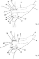
- Figure 1 shows a device in accordance with the present invention in the form of an earplug 2.
- the earplug 2 is inserted into a user's ear canal 4.
- the user's ear canal 4 extends to the tympanic membrane 6.
- the tympanic membrane 6 vibrates in response to incident sound waves which travel along the ear canal 4.
- the earplug 2 comprises a sealing plug 8, a control circuit 10, an electric actuator 12, a valve 14, and an internal channel 16 which runs through the sealing plug 8.
- a gasket 18 is provided at the opening of the internal channel 16 which is exposed to the external environment.
- the internal channel 16 and thus the opening may have any desired cross sectional shape.
- An acoustic leak channel 20 connects the outside environment to the internal channel 16.
- the acoustic leak channel 20 allows a certain amount of sound to pass into the channel 16 irrespective of the position of the valve 14 and provides pressure equalisation when the valve is closed. When the valve 14 is completely closed, the acoustic leak channel 20 controls the level of attenuation.
- the control circuit 10, electric motor 12 and acoustic leak channel 20 are provided in a segmented portion 22 of the sealing plug 8.
- the valve 14 comprises a moveable member with a sealing face 24 for sealing against the gasket 18.
- the valve member 14 is pivotally mounted to a protruding member 26 which extends from the main body of the earplug 2.
- the distal end 28 of the valve 14 is acted on by an armature 30 which is driven by the actuator 12.
- a user can insert the earplug 2 into their ear canal 4 to the point at which a good seal between the sealing plug 8 and ear canal 4 is achieved.
- the control circuit 10 then controls the level of attenuation of the earplug 2.
- the earplug is in a first configuration which provides a first level of attenuation.
- the valve 14 is completely open and thus the earplug provides minimal attenuation of the sound which enters the user's ear canal 4.
- the control circuit 10 operates the motor 12 such that the actuator 12 pulls on distal end 28 of the valve 14 so that it pivots and moves the sealing face 24 away from the gasket 18. This opens up the channel 16 allowing sound to propagate along the channel 16 towards the tympanic membrane 6.
- Figure 2 shows the same earplug 2 in the second configuration which provides a second level of attenuation.
- the valve 14 is able to significantly reduce the sound passing through the valve 14 directly into the internal channel 16 and thus the user's ear canal 4. Therefore, in this configuration, sound which can enter the user's ear canal 4 is sound which has travelled via the acoustic leak channel 20 and the sound which has been attenuated by the valve 14.
- the acoustic leak channel 20 is designed such that it attenuates sound. As a result the sound intensity which can propagate through the acoustic leak channel 20 is significantly less than the sound which can propagate through the earplug 2 when the valve 14 is opened.
- the actuator 12 drives the armature 30 to push on the distal end 28 of the valve 14 so that the end portion 24 is pivoted to seal against the gasket 18.
- valve 14 may be positioned so as to be proximal to the gasket 18 but not forming a complete seal.
- This configuration may provide a third level of attenuation in between the levels achieved by the configurations seen in Figures 1 and 2 . It will be appreciated that there is a continuous range of positions of the valve 14 which will be equivalent to different levels of attenuation and thus a range of different attenuation levels may be achieved using this example embodiment.
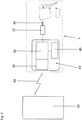
- FIG. 3 shows a schematic diagram of the earplug 2 interacting with an external device, for example a smart phone 32.
- the earplug 2 and smart phone 32 communicate via a radio link 34 which could, for example, be a BluetoothTM connection.
- the control circuit 10, within the earplug 2 comprises a receiver unit 36, a control system 38 and a battery circuit 40.
- the battery circuit 40 powers the control system 38 and receiver unit 36.
- the control system 38 controls the output of the actuator 12 which moves the armature 30 which controls the position of the valve 14.
- the earplug 2 may receive a radio signal 34 from the smartphone 32 to instruct the earplug to operate in a second configuration equivalent to a second level of attenuation.
- the receiver 36 receives this radio signal which is subsequently interpreted by the control system 38.
- the actuator 12 is then driven so as to cause the valve 14 to close and thus the earplug 2 attenuates incoming sound at the second level of attenuation.
- a radio signal 34 is received from the smart phone 32 to instruct the earplug to operate in a first configuration in which the level of attenuation is lower, this can once again be received by receiver 36, interpreted by control circuit 38 and cause the motor 12 to be driven as to move the valve 14 into the open position allowing sound to freely travel into the user's ear canal 4.
- a user may have the earplug 2 in their ear and have the earplug 2 in a first configuration in which the valve 2 is open (see Fig. 1 ).
- a user When a user enters a noisy environment, for example one in which power tools are being used, they may switch the earplug 2 to the second configuration in which the valve 2 is closed (see Fig. 2 ).
- the user When making this transition between different environments the user may, for example, press a button on the mobile device 32 in order to provide a command to switch between the two different configurations.
- the mobile device 32 may comprise a microphone and sound processing software.
- the microphone may detect the sound intensity in the environment in which it is in. As the mobile device 32 is likely to be carried by the user it will detect the sound intensity in the environment proximal to the user.
- the sound processing software can then measure the intensity of the sound and compare it to predetermined base levels. If the sound is determined to be above a predetermined base level the mobile device 32 may provide a command signal to the earplug 2 to switch it into the second configuration.
- the sound processing software may also monitor the detected sound levels and assess any frequent sounds which may be below the base level but may still cause damage to the user's hearing due to their repetitive nature. The mobile device 32 may then cause the earplug 2 to switch to the second configuration if such conditions are detected.
- the mobile device 32 may continue to monitor the sound intensity in the environment in which the user is present. If/when the mobile device 32 detects that the sound conditions have changed, the mobile device 32 may provide a command signal to switch the earplug 2 into the first configuration. This ability to constantly monitor the sound conditions via the mobile device is advantageous as it does not require power consumption from the earplug 2 itself.
- the receiver 36 may relay various pieces of operational state information to the smartphone, for example battery status information. This information may then be used by the smartphone and be used to indicate to the user when the batteries need replacing or recharging.
Landscapes
- Engineering & Computer Science (AREA)
- Health & Medical Sciences (AREA)
- Physics & Mathematics (AREA)
- Life Sciences & Earth Sciences (AREA)
- Theoretical Computer Science (AREA)
- Acoustics & Sound (AREA)
- Biophysics (AREA)
- Animal Behavior & Ethology (AREA)
- Veterinary Medicine (AREA)
- Public Health (AREA)
- General Health & Medical Sciences (AREA)
- Otolaryngology (AREA)
- Psychology (AREA)
- Biomedical Technology (AREA)
- Heart & Thoracic Surgery (AREA)
- Vascular Medicine (AREA)
- General Engineering & Computer Science (AREA)
- General Physics & Mathematics (AREA)
- Signal Processing (AREA)
- Computer Networks & Wireless Communication (AREA)
- Circuit For Audible Band Transducer (AREA)
Description
- This invention relates to ear protection used for reducing the intensity of sounds experienced by a user.
- Exposure to high intensity noises can cause damage to a person's hearing. The damaging effects are increased when a person is frequently exposed to loud noises. In extreme cases, frequent exposure to loud noises can cause noise-induced hearing loss. Therefore, in order to protect hearing it is necessary to reduce the effects of continuous, intermittent and impact noises. As a result of the increasing awareness of the damaging effects of loud noises from industrial sources, there are various industry requirements for personnel to use ear protection. There are many situations in which personnel may be exposed to loud noises, for example when operating loud machinery. A common form of noise protection widely used are earplugs, these reduce the intensity of the sound entering a person's ears and thus reduce the damaging effects of high intensity noises.
- There are two main types of earplugs that are commonly used: passive earplugs and active earplugs. Passive earplugs attenuate the intensity of all levels of sound equally, i.e. they provide a certain level of sound reduction, for example, a reduction of 20 dB. Passive earplugs come in various forms including: foam, silicon, flanged and custom moulded earplugs. Passive earplugs are typically inserted into a user's ear canal and, once in position, the material of the earplug acts to attenuate the sound which passes through it. As the incident sound passes through the earplug it is attenuated and subsequently passes out of the earplug into the user's ear canal where it is detected by the user.
- Active earplugs comprise electronic components which enable the earplug to attenuate high intensity sounds. Active earplugs often comprise a passive earplug used in conjunction with a microphone on the external side of the earplug and a speaker on the internal side of the earplug. Active earplugs can employ control circuitry to apply different levels of attenuation at different times or different frequencies - known as 'adaptive attenuation'. Some systems contain circuitry that detects the incident sound and produces an out-of-phase signal that destructively interferes with the incident sound thus reducing the intensity of the incident sound as it propagates into the user's ear canal - this is often known as 'active noise cancelling' .
-
US 2012/082335 2012/00023302 - When viewed from a first aspect the present invention provides a device for insertion into an ear canal of a mammalian subject and defining at least one sound path therethrough, as recited in claim 1.
- Thus it will be seen by those skilled in the art that by providing at least two different levels of attenuation, which can be changed using the device itself, the device can be used in different situations which require different levels of attenuation without needing to physically remove the device. For example, if a user is operating heavy machinery the device may be operated in the second configuration in which the level of attenuation is higher, and then when a user stops using the heavy machinery, and the need for noise protection is reduced, the device may switch to the first configuration. This may, for example, allow the user to be able to hear quieter sounds such as conversations between other colleagues or other ambient noises.
- Having to repeatedly remove and replace passive earplugs may cause users to avoid wearing them and thus potentially damage their hearing. The present invention may help to address this issue by removing the need to remove the device in order to switch between different levels of attenuation. As the device is able to switch between the two configurations upon receipt of a command signal, the device does not need to be physically removed as often and thus a user may therefore be more inclined to use it than risking their hearing.
- It will also be understood that having two stable configurations of the mechanical attenuation components means that the device is effectively 'semi-active' in that the attenuating arrangement only uses electrical current to switch between the configurations but does not draw current during the rest of its operation. It will be appreciated that this is particularly advantageous as the device may only require electrical power for relatively short periods of time which may be relatively infrequent. The significant reduction in the amount of electrical power required to operate the device which this may provide could mean that such embodiments will have an improved battery life. This may mean that either a smaller battery can be used, potentially allowing the size of the device to be reduced, or alternatively it may simply extend the operational period of the device. Extending the battery life may be advantageous as it would reduce the requirement on a user to either recharge or replace the batteries in the device. Alternatively, providing a smaller battery may mean that the device can be lighter and more compact potentially meaning that it is more comfortable for the user. This is a significant improvement over active earplugs which constantly draw power in order operate their electronic control circuitry which monitors and adapts the earplug depending on the detected sound. Such active earplugs are well known to have a heavy power consumption and require frequent charging or battery replacement. It is also advantageous over arrangements which require power in order to maintain a particular level of attenuation e.g. a piezoelectric acoustic valve.
- The device could, for example, operate in a default configuration which corresponds to the second configuration. After receiving the command signal to change from the second configuration to the first configuration, the device may be arranged to switch back automatically to the second configuration after a predetermined condition has been met, for example a period of time has elapsed. This may allow the user to be able to listen to quieter sounds such as a comment from a colleague for a short period of time before returning to the second configuration in which the level of attenuation is higher and thus providing more protection without the user having to remember to do so.
- In a set of embodiments however said command signal causes the attenuating arrangement to change from said first configuration to said second configuration and receipt of a second command signal causes said attenuating arrangement to change from said second configuration to said first configuration. Such embodiments allow the device to be remotely controlled to switch between each configuration by a remote device. This may, for example, allow the user to have increased control over the operation of the device, allowing them to determine the configuration in which it is operating.
- In a set of embodiments said attenuating arrangement has a third configuration having a third level of attenuation between the first and second levels. Such a set of embodiments is particularly advantageous as it may allow the device to be used in an increased number of situations. For example, such a set of embodiments would be highly useful in environments where there is intermediate-level noise, which is louder than an accepted base line noise but not as loud as significant impact noises. It is known that extended exposure to mid-level can cause hearing damage. Therefore, by having a third configuration, it means that the user may use the device to protect against the harmful mid-level noise. Increasing the number of situations in which the device can be used increases the chance of users making better use of the device and properly protecting their hearing. In another set of embodiments the attenuating arrangement may have any number of discrete levels of attenuation. Alternatively, in a set of embodiments the level of attenuation may be continuously variable. It will be appreciated by those skilled in the art that by providing a large number of attenuating arrangements or a continuously variable level of attenuation the device may be used in an increased number of situations/environments.
- In a further set of embodiments where the attenuating arrangement has a third configuration the receipt of a third command signal causes said attenuating arrangement to change to said third configuration. This allows the device to be further controlled by an external device. In embodiments where the attenuating arrangement has a different number of levels of attenuation or a continuously variable level of attenuation a command signal may be provided from an external device to switch the attenuating arrangement into the configuration which corresponds to the level of attenuation.
- It will be appreciated that the receiver within device may take various forms. However, in a set of embodiments said receiver is a radio-frequency (RF) receiver. A RF receiver is particularly advantageous as it does not require line of sight operation, and thus it may receive signals from a host of different devices, for example a user's mobile phone. In a further set of embodiments said receiver is Bluetooth™ compatible. This allows the device to receive commands from readily available electrical items, for example smart phones. In a further set of embodiments the receiver may comprise a Radio Frequency Identification Device (RFID) which receives power from an external device. Such a set of embodiments is further advantageous as the receiver is powered by the external device and thus does not draw power from a power supply within the device. This may help to increase the battery life of the device increasing its operational time.
- In a set of embodiments the receiver operates in a sleep mode in which minimal power is drawn. This is particularly advantageous as the power consumption of the device is further reduced, thus extending the operational use of the battery.
- The command signal is provided by a smart phone. It will be appreciated that using a smart phone is particularly advantageous as many people now own smart phones and thus it is likely that a user will have a smart phone that can be used with the device.
- In a further set of embodiments the smart phone is provided with control software, for example in the form of a software application. This may allow the user to control the device easily. For example, it may allow the user to cause the device to switch between different configurations. The use of a smart phone, is also useful as they often comprise a microphone capable of detecting sounds. In a set of embodiments the smart phone comprises a microphone which is used as part of a sound level meter. It will be appreciated that this set of embodiments is particularly advantageous as the smart phone can be used to detect the intensity of incident sounds and may control the device accordingly. For example, if the smart phone detects a particularly loud sound it may send a command signal to the device in order to switch it into the second configuration. Conversely, if the smart phone detects low sound levels it may send a command signal to the device in order to switch it into the first configuration.
- The attenuating arrangement may comprise any number of mechanical components which can affect the level of attenuation of the device. In a set of embodiments the attenuating arrangement comprises an electrical motor or actuator, for example a piezo-electric actuator or motor with a screw. In such a set of embodiments the electric motor or actuator may be employed to adjust the configuration of the mechanical arrangement between its stable states to provide the level of attenuation in such a way that the electric motor or actuator only need electrical current when moving between each configuration. In a set of embodiments the attenuating arrangement comprises a valve. It will be understood that the valve effectively controls the intensity of the sound which propagates through the device. The state of the valve therefore changes the level of attenuation. Therefore, adjusting the state of the valve effectively switches the device between different configurations.
- In a set of embodiments the first level of attenuation is less than 25 dB, e.g.less than 10 dB, e.g. less than 5 dB. In embodiments where the first level of attenuation is less than 5 dB it is intended that whilst the device is in this configuration there is no deliberate attenuation of the incident sound (although a small degree of attenuation is inevitable).
- The level of sound protection provided by the device is particularly important, particularly to meet prescribed health and safety requirements. The level of attenuation of the first configuration and the second configuration may be in a wide range of levels. However, in a set of embodiments said first and second attenuation levels differ by less than 25dB. This level of attenuation is considered to be an intermediate level of attenuation and as a result the device does not need to be inserted too far within the user's ear canal. As a result the device is suitable for situations which require mid-level attenuation. It is known that it is these specific mid-level noise environments where, due to the inconvenience of typical earplugs, a user may be more likely to take a risk and avoid wearing protection due to convenience. By providing a device that provides appropriate protection for these mid-level sound intensities, without the inconveniences of a typical earplug, a user may be more inclined to use the device and protect their hearing.
- In a set of embodiments the device is in the form of an earplug adapted to conform tightly to the ear canal. It will be appreciated that an earplug which conforms tightly to the ear canal helps to prevent sound entering the ear canal without passing through the device, therefore helping to reduce the risk of high intensity sounds damaging the ear. This ultimately ensures that the device is able to control the sound level entering the ear canal. It is also important that the device conforms tightly to the ear canal to prevent the device from becoming loose or falling out. As the device may be used in environments where a user may be physically active the chances of the device becoming loose are increased, therefore this embodiment helps to reduce this risk of the device becoming loose and thus ensures contestant protection for the user.
- Whilst the device may switch between configurations upon receipt of a command signal by the receiver it may also be possible to control the device directly from the device itself. In a set of embodiments the device comprises at least one button on the device and in operative connection with the attenuating arrangement. By touching the button a control signal may be sent to the attenuating arrangement. It will be appreciated that the provision of at least one button on the device may be advantageous as it may allow the user to easily switch between configurations without having to operate a further device. This may, for example, be useful as ear protection devices are often used in adverse conditions where controlling a further device may not be feasible.
- Certain embodiments of the present invention will now be described, by way of example only, with reference to the accompanying drawings, in which:
-
Fig.1 shows a schematic view of a device in accordance with the present invention in a first configuration; -
Fig. 2 shows a schematic view of the device ofFig. 1 in a second configuration; and -
Fig. 3 shows a schematic of the control circuitry of the device ofFigs 1 and 2 . -
Figure 1 shows a device in accordance with the present invention in the form of anearplug 2. Theearplug 2 is inserted into a user'sear canal 4. The user'sear canal 4 extends to thetympanic membrane 6. Thetympanic membrane 6 vibrates in response to incident sound waves which travel along theear canal 4. - The
earplug 2 comprises a sealingplug 8, acontrol circuit 10, anelectric actuator 12, avalve 14, and aninternal channel 16 which runs through the sealingplug 8. Agasket 18 is provided at the opening of theinternal channel 16 which is exposed to the external environment. Theinternal channel 16 and thus the opening may have any desired cross sectional shape. Anacoustic leak channel 20 connects the outside environment to theinternal channel 16. Theacoustic leak channel 20 allows a certain amount of sound to pass into thechannel 16 irrespective of the position of thevalve 14 and provides pressure equalisation when the valve is closed. When thevalve 14 is completely closed, theacoustic leak channel 20 controls the level of attenuation. Thecontrol circuit 10,electric motor 12 andacoustic leak channel 20 are provided in asegmented portion 22 of the sealingplug 8. - The
valve 14 comprises a moveable member with a sealingface 24 for sealing against thegasket 18. Thevalve member 14 is pivotally mounted to a protrudingmember 26 which extends from the main body of theearplug 2. Thedistal end 28 of thevalve 14 is acted on by anarmature 30 which is driven by theactuator 12. - In order to protect their hearing, a user can insert the
earplug 2 into theirear canal 4 to the point at which a good seal between the sealingplug 8 andear canal 4 is achieved. Thecontrol circuit 10 then controls the level of attenuation of theearplug 2. In the embodiment seen inFigure 1 the earplug is in a first configuration which provides a first level of attenuation. Thevalve 14 is completely open and thus the earplug provides minimal attenuation of the sound which enters the user'sear canal 4. In order to achieve this configuration thecontrol circuit 10 operates themotor 12 such that theactuator 12 pulls ondistal end 28 of thevalve 14 so that it pivots and moves the sealingface 24 away from thegasket 18. This opens up thechannel 16 allowing sound to propagate along thechannel 16 towards thetympanic membrane 6. - The level of attenuation provided by the earplug can be determined by comparing the sound pressure outside the
ear canal 4 and the sound pressure inside theear canal 4. This can be calculated by using the following formula: Attenuation[dB] = Pout [dB] - Pin [dB] where Pin [dB] is the sound pressure inside theear canal 4 measured in decibels and Pout [dB] is the sound pressure outside theear canal 4 also measuring in decibels. The relationship between the pressure in decibels and the pressure in Pascals is given by the following relationship: P[dB] = 20log(p/p 0), where P[dB] is the pressure in decibels, p is the pressure in Pascals, and p 0 is a reference pressure p 0 = 2 × 10⁻⁵ Pascals. If the pressures are measured in Pascals, the attenuation can be calculated using the following formula: Attenuation = p out/ pin , where pin is the pressure inside the ear canal measured in pascals, and pout is the pressure outside the ear canal measured in pascals. This way of calculating attenuation gives a dimensionless number typically in the range from one to several thousand (if the attenuation is high). -
Figure 2 shows thesame earplug 2 in the second configuration which provides a second level of attenuation. In this configuration it will be appreciated that a significant portion of the sound which travels towards the user's ear will be attenuated. It is envisaged that thevalve 14 is able to significantly reduce the sound passing through thevalve 14 directly into theinternal channel 16 and thus the user'sear canal 4. Therefore, in this configuration, sound which can enter the user'sear canal 4 is sound which has travelled via theacoustic leak channel 20 and the sound which has been attenuated by thevalve 14. Theacoustic leak channel 20 is designed such that it attenuates sound. As a result the sound intensity which can propagate through theacoustic leak channel 20 is significantly less than the sound which can propagate through theearplug 2 when thevalve 14 is opened. - In order for the
earplug 2 to operate in this second configuration, theactuator 12 drives thearmature 30 to push on thedistal end 28 of thevalve 14 so that theend portion 24 is pivoted to seal against thegasket 18. - It will be appreciated that whilst
Figures 1 and 2 only show two configurations in which two distinct levels of attenuation are achieved, it is envisaged that other levels of attenuation could be achieved. For example, thevalve 14 may be positioned so as to be proximal to thegasket 18 but not forming a complete seal. This configuration may provide a third level of attenuation in between the levels achieved by the configurations seen inFigures 1 and 2 . It will be appreciated that there is a continuous range of positions of thevalve 14 which will be equivalent to different levels of attenuation and thus a range of different attenuation levels may be achieved using this example embodiment. -
Figure 3 shows a schematic diagram of theearplug 2 interacting with an external device, for example asmart phone 32. Theearplug 2 andsmart phone 32 communicate via aradio link 34 which could, for example, be a Bluetooth™ connection. Thecontrol circuit 10, within theearplug 2, comprises a receiver unit 36, acontrol system 38 and abattery circuit 40. Thebattery circuit 40 powers thecontrol system 38 and receiver unit 36. Thecontrol system 38 controls the output of theactuator 12 which moves thearmature 30 which controls the position of thevalve 14. - During use, the
earplug 2 may receive aradio signal 34 from thesmartphone 32 to instruct the earplug to operate in a second configuration equivalent to a second level of attenuation. In this case, the receiver 36 receives this radio signal which is subsequently interpreted by thecontrol system 38. Theactuator 12 is then driven so as to cause thevalve 14 to close and thus theearplug 2 attenuates incoming sound at the second level of attenuation. In contrast, if aradio signal 34 is received from thesmart phone 32 to instruct the earplug to operate in a first configuration in which the level of attenuation is lower, this can once again be received by receiver 36, interpreted bycontrol circuit 38 and cause themotor 12 to be driven as to move thevalve 14 into the open position allowing sound to freely travel into the user'sear canal 4. - A user may have the
earplug 2 in their ear and have theearplug 2 in a first configuration in which thevalve 2 is open (seeFig. 1 ). When a user enters a noisy environment, for example one in which power tools are being used, they may switch theearplug 2 to the second configuration in which thevalve 2 is closed (seeFig. 2 ). When making this transition between different environments the user may, for example, press a button on themobile device 32 in order to provide a command to switch between the two different configurations. - In other embodiments, the
mobile device 32 may comprise a microphone and sound processing software. In such embodiments the microphone may detect the sound intensity in the environment in which it is in. As themobile device 32 is likely to be carried by the user it will detect the sound intensity in the environment proximal to the user. The sound processing software can then measure the intensity of the sound and compare it to predetermined base levels. If the sound is determined to be above a predetermined base level themobile device 32 may provide a command signal to theearplug 2 to switch it into the second configuration. The sound processing software may also monitor the detected sound levels and assess any frequent sounds which may be below the base level but may still cause damage to the user's hearing due to their repetitive nature. Themobile device 32 may then cause theearplug 2 to switch to the second configuration if such conditions are detected. - Once the
earplug 2 is in a configuration appropriate for the detected sound levels, themobile device 32 may continue to monitor the sound intensity in the environment in which the user is present. If/when themobile device 32 detects that the sound conditions have changed, themobile device 32 may provide a command signal to switch theearplug 2 into the first configuration. This ability to constantly monitor the sound conditions via the mobile device is advantageous as it does not require power consumption from theearplug 2 itself. - It will also be appreciated that there may be communication from the receiver 36 to the
smartphone 32. For example the receiver may relay various pieces of operational state information to the smartphone, for example battery status information. This information may then be used by the smartphone and be used to indicate to the user when the batteries need replacing or recharging. - It will be appreciated that whilst in the example shown a
motor 12 drives avalve 14 to open and close aninternal channel 16, various other mechanisms could be employed.
Claims (17)
- A device (2) for insertion into an ear canal (4) of a mammalian subject and defining at least one sound path therethrough, the sound path having an attenuating arrangement therein which has a first configuration having a first level of attenuation and a second configuration having a second level of attenuation, higher than the first level, the attenuating arrangement being such that upon application of an electrical control signal thereto it is caused to change between said first and second configurations; the attenuating arrangement being stable in both first and second configurations such that the attenuating arrangement only draws electrical current from a power source when changing between the first and second configurations; characterised in that the device further comprises a receiver (36) for receiving a command signal from a smartphone such that receipt of said command signal causes said electrical control signal to be applied to said attenuating arrangement.
- The device (2) as claimed in claim 1 arranged such that said command signal causes the attenuating arrangement to change from said first configuration to said second configuration and receipt of a second command signal causes said attenuating arrangement to change from said second configuration to said first configuration.
- The device (2) as claimed in claim 1 or 2 wherein said attenuating arrangement has a third configuration having a third level of attenuation between the first and second levels.
- The device (2) as claimed in claim 2 wherein receipt of a third command signal causes said attenuating arrangement to change to said third configuration.
- The device (2) as claimed in any preceding claim wherein said receiver (36) is a radio-frequency receiver.
- The device (2) as claimed in any preceding claim wherein said receiver (36) is Bluetooth™ compatible.
- The device (2) as claimed in any preceding claim wherein the receiver (36) comprises a Radio Frequency Identification Device which is configured to receive power from an external device.
- The device (2) as claimed in any preceding claim wherein the receiver (36) is arranged to operate in a sleep mode in which minimal power is drawn.
- The device (2) as claimed in any preceding claim wherein the smart phone (32) is provided with control software, for example in the form of a software application.
- The device (2) as claimed in any preceding claim wherein the smart phone (32) comprises a microphone which is used as part of a sound level meter.
- The device (2) as claimed in any preceding claim wherein the attenuating arrangement comprises an electrical motor or actuator (12).
- The device (2) as claimed in claim 11 wherein the electric motor or actuator (12) is employed to adjust the mechanical arrangement between said first and second configurations in such a way that the electric motor or actuator only needs electrical current when moving between said configurations.
- The device (2) as claimed in any preceding claim wherein the attenuating arrangement comprises a valve (14).
- The device (2) as claimed in any preceding claim wherein the first level of attenuation is less than 25 dB.
- The device (2) as claimed in any preceding claim wherein said first and second attenuation levels differ by less than 25dB.
- The device (2) as claimed in any preceding claim comprising at least a portion thereof in a form of an earplug adapted to conform tightly to a user's ear canal (4).
- The device (2) as claimed in any preceding claim comprising at least one button on the device and in operative connection with the attenuating arrangement.
Applications Claiming Priority (2)
| Application Number | Priority Date | Filing Date | Title |
|---|---|---|---|
| GBGB1609033.4A GB201609033D0 (en) | 2016-05-23 | 2016-05-23 | Ear protection device |
| PCT/GB2017/051410 WO2017203218A1 (en) | 2016-05-23 | 2017-05-19 | Ear protection device |
Publications (2)
| Publication Number | Publication Date |
|---|---|
| EP3463232A1 EP3463232A1 (en) | 2019-04-10 |
| EP3463232B1 true EP3463232B1 (en) | 2020-04-29 |
Family
ID=56369806
Family Applications (1)
| Application Number | Title | Priority Date | Filing Date |
|---|---|---|---|
| EP17726671.5A Active EP3463232B1 (en) | 2016-05-23 | 2017-05-19 | Ear protection device |
Country Status (4)
| Country | Link |
|---|---|
| US (1) | US20200046563A1 (en) |
| EP (1) | EP3463232B1 (en) |
| GB (1) | GB201609033D0 (en) |
| WO (1) | WO2017203218A1 (en) |
Families Citing this family (7)
| Publication number | Priority date | Publication date | Assignee | Title |
|---|---|---|---|---|
| NL2020330B1 (en) * | 2018-01-26 | 2019-07-31 | Dynamic Ear Company B V | Acoustic filter with attenuation control |
| GB201903920D0 (en) * | 2019-03-21 | 2019-05-08 | Minuendo As | Ear protection |
| GB201903912D0 (en) * | 2019-03-21 | 2019-05-08 | Minuendo As | Ear protection |
| DE102019120823B4 (en) * | 2019-08-01 | 2022-02-17 | Robert Hitz | Hearing protectors with opening that can be changed by changing the position of the head |
| WO2021115603A1 (en) * | 2019-12-12 | 2021-06-17 | Huawei Technologies Co., Ltd. | Flat magnetic valve for insert headsets |
| NL2025161B1 (en) * | 2020-03-18 | 2021-10-20 | Ernst Frankhauser Matthew | Hearing protection system and method of hearing protection |
| WO2023148507A1 (en) * | 2022-02-04 | 2023-08-10 | Minuendo As | Hearing protection |
Family Cites Families (4)
| Publication number | Priority date | Publication date | Assignee | Title |
|---|---|---|---|---|
| NO314380B1 (en) * | 2000-09-01 | 2003-03-10 | Nacre As | Ear terminal |
| EP1880699B1 (en) * | 2004-08-25 | 2015-10-07 | Sonova AG | Method for manufacturing an earplug |
| KR101689339B1 (en) * | 2009-06-02 | 2016-12-23 | 코닌클리케 필립스 엔.브이. | Earphone arrangement and method of operation therefor |
| US8649540B2 (en) * | 2009-10-30 | 2014-02-11 | Etymotic Research, Inc. | Electronic earplug |
-
2016
- 2016-05-23 GB GBGB1609033.4A patent/GB201609033D0/en not_active Ceased
-
2017
- 2017-05-19 US US16/304,230 patent/US20200046563A1/en not_active Abandoned
- 2017-05-19 WO PCT/GB2017/051410 patent/WO2017203218A1/en not_active Ceased
- 2017-05-19 EP EP17726671.5A patent/EP3463232B1/en active Active
Non-Patent Citations (1)
| Title |
|---|
| None * |
Also Published As
| Publication number | Publication date |
|---|---|
| WO2017203218A1 (en) | 2017-11-30 |
| US20200046563A1 (en) | 2020-02-13 |
| GB201609033D0 (en) | 2016-07-06 |
| EP3463232A1 (en) | 2019-04-10 |
Similar Documents
| Publication | Publication Date | Title |
|---|---|---|
| US20200046563A1 (en) | Ear protection device | |
| CN111385727B (en) | Method for determining the state of a sound feedback path of a head-mounted hearing device and hearing device | |
| CN111357300B (en) | AC installations including acoustic seals and drain openings | |
| CN1897896B (en) | Earplug | |
| US20140294191A1 (en) | Hearing Protection with Sound Exposure Control and Monitoring | |
| CN105706463B (en) | Adaptive frequency response for hearing protectors, adaptive automatic level control, and handling radio communications | |
| CN113826157B (en) | Audio system and signal processing method for ear-worn playback devices | |
| US9066167B2 (en) | Method and device for personalized voice operated control | |
| EP2415276B1 (en) | Personal acoustic device position determination | |
| EP2835987A1 (en) | Hearing aid having controllable vent | |
| EP3799443B1 (en) | Hearing device comprising an active vent and method for its operation | |
| EP3637799B1 (en) | Hearing device comprising a housing with a venting passage | |
| EP2309773A1 (en) | Earphone with leakage control and device therefor | |
| CN101090687B (en) | Hearing protector | |
| WO2014022359A2 (en) | Automatic sound pass-through method and system for earphones | |
| WO2009012491A2 (en) | Device and method for remote acoustic porting and magnetic acoustic connection | |
| CN107005757A (en) | Mitigate itself speech obstruction in earphone | |
| WO2011033136A2 (en) | Dynamic hearing protection device and method | |
| US11044546B1 (en) | Mode controlled acoustic leak mechanism to optimize audio performance | |
| US20230292059A1 (en) | Hearing aids providing protection against sudden loud sounds | |
| CN118160030A (en) | Broad spectrum instability detection and mitigation | |
| EP4451699B1 (en) | Active hearing protection device | |
| KR20100119470A (en) | Wireless head set apparatus equipped with mic combined with earphone and monitoring function | |
| AU2010358921A1 (en) | Method for operating a hearing aid and corresponding hearing aid | |
| WO2022271262A1 (en) | Acoustic earwax detection |
Legal Events
| Date | Code | Title | Description |
|---|---|---|---|
| STAA | Information on the status of an ep patent application or granted ep patent |
Free format text: STATUS: UNKNOWN |
|
| STAA | Information on the status of an ep patent application or granted ep patent |
Free format text: STATUS: THE INTERNATIONAL PUBLICATION HAS BEEN MADE |
|
| PUAI | Public reference made under article 153(3) epc to a published international application that has entered the european phase |
Free format text: ORIGINAL CODE: 0009012 |
|
| STAA | Information on the status of an ep patent application or granted ep patent |
Free format text: STATUS: REQUEST FOR EXAMINATION WAS MADE |
|
| 17P | Request for examination filed |
Effective date: 20181219 |
|
| AK | Designated contracting states |
Kind code of ref document: A1 Designated state(s): AL AT BE BG CH CY CZ DE DK EE ES FI FR GB GR HR HU IE IS IT LI LT LU LV MC MK MT NL NO PL PT RO RS SE SI SK SM TR |
|
| AX | Request for extension of the european patent |
Extension state: BA ME |
|
| DAV | Request for validation of the european patent (deleted) | ||
| DAX | Request for extension of the european patent (deleted) | ||
| GRAP | Despatch of communication of intention to grant a patent |
Free format text: ORIGINAL CODE: EPIDOSNIGR1 |
|
| STAA | Information on the status of an ep patent application or granted ep patent |
Free format text: STATUS: GRANT OF PATENT IS INTENDED |
|
| INTG | Intention to grant announced |
Effective date: 20200124 |
|
| GRAS | Grant fee paid |
Free format text: ORIGINAL CODE: EPIDOSNIGR3 |
|
| GRAA | (expected) grant |
Free format text: ORIGINAL CODE: 0009210 |
|
| STAA | Information on the status of an ep patent application or granted ep patent |
Free format text: STATUS: THE PATENT HAS BEEN GRANTED |
|
| AK | Designated contracting states |
Kind code of ref document: B1 Designated state(s): AL AT BE BG CH CY CZ DE DK EE ES FI FR GB GR HR HU IE IS IT LI LT LU LV MC MK MT NL NO PL PT RO RS SE SI SK SM TR |
|
| REG | Reference to a national code |
Ref country code: GB Ref legal event code: FG4D |
|
| REG | Reference to a national code |
Ref country code: CH Ref legal event code: EP |
|
| REG | Reference to a national code |
Ref country code: AT Ref legal event code: REF Ref document number: 1262225 Country of ref document: AT Kind code of ref document: T Effective date: 20200515 |
|
| REG | Reference to a national code |
Ref country code: DE Ref legal event code: R096 Ref document number: 602017015742 Country of ref document: DE |
|
| REG | Reference to a national code |
Ref country code: IE Ref legal event code: FG4D |
|
| REG | Reference to a national code |
Ref country code: NL Ref legal event code: MP Effective date: 20200429 |
|
| REG | Reference to a national code |
Ref country code: LT Ref legal event code: MG4D |
|
| PG25 | Lapsed in a contracting state [announced via postgrant information from national office to epo] |
Ref country code: SE Free format text: LAPSE BECAUSE OF FAILURE TO SUBMIT A TRANSLATION OF THE DESCRIPTION OR TO PAY THE FEE WITHIN THE PRESCRIBED TIME-LIMIT Effective date: 20200429 Ref country code: LT Free format text: LAPSE BECAUSE OF FAILURE TO SUBMIT A TRANSLATION OF THE DESCRIPTION OR TO PAY THE FEE WITHIN THE PRESCRIBED TIME-LIMIT Effective date: 20200429 Ref country code: PT Free format text: LAPSE BECAUSE OF FAILURE TO SUBMIT A TRANSLATION OF THE DESCRIPTION OR TO PAY THE FEE WITHIN THE PRESCRIBED TIME-LIMIT Effective date: 20200831 Ref country code: IS Free format text: LAPSE BECAUSE OF FAILURE TO SUBMIT A TRANSLATION OF THE DESCRIPTION OR TO PAY THE FEE WITHIN THE PRESCRIBED TIME-LIMIT Effective date: 20200829 Ref country code: GR Free format text: LAPSE BECAUSE OF FAILURE TO SUBMIT A TRANSLATION OF THE DESCRIPTION OR TO PAY THE FEE WITHIN THE PRESCRIBED TIME-LIMIT Effective date: 20200730 Ref country code: FI Free format text: LAPSE BECAUSE OF FAILURE TO SUBMIT A TRANSLATION OF THE DESCRIPTION OR TO PAY THE FEE WITHIN THE PRESCRIBED TIME-LIMIT Effective date: 20200429 Ref country code: NO Free format text: LAPSE BECAUSE OF FAILURE TO SUBMIT A TRANSLATION OF THE DESCRIPTION OR TO PAY THE FEE WITHIN THE PRESCRIBED TIME-LIMIT Effective date: 20200729 |
|
| REG | Reference to a national code |
Ref country code: AT Ref legal event code: MK05 Ref document number: 1262225 Country of ref document: AT Kind code of ref document: T Effective date: 20200429 |
|
| PG25 | Lapsed in a contracting state [announced via postgrant information from national office to epo] |
Ref country code: LV Free format text: LAPSE BECAUSE OF FAILURE TO SUBMIT A TRANSLATION OF THE DESCRIPTION OR TO PAY THE FEE WITHIN THE PRESCRIBED TIME-LIMIT Effective date: 20200429 Ref country code: HR Free format text: LAPSE BECAUSE OF FAILURE TO SUBMIT A TRANSLATION OF THE DESCRIPTION OR TO PAY THE FEE WITHIN THE PRESCRIBED TIME-LIMIT Effective date: 20200429 Ref country code: BG Free format text: LAPSE BECAUSE OF FAILURE TO SUBMIT A TRANSLATION OF THE DESCRIPTION OR TO PAY THE FEE WITHIN THE PRESCRIBED TIME-LIMIT Effective date: 20200729 Ref country code: RS Free format text: LAPSE BECAUSE OF FAILURE TO SUBMIT A TRANSLATION OF THE DESCRIPTION OR TO PAY THE FEE WITHIN THE PRESCRIBED TIME-LIMIT Effective date: 20200429 |
|
| PG25 | Lapsed in a contracting state [announced via postgrant information from national office to epo] |
Ref country code: AL Free format text: LAPSE BECAUSE OF FAILURE TO SUBMIT A TRANSLATION OF THE DESCRIPTION OR TO PAY THE FEE WITHIN THE PRESCRIBED TIME-LIMIT Effective date: 20200429 Ref country code: NL Free format text: LAPSE BECAUSE OF FAILURE TO SUBMIT A TRANSLATION OF THE DESCRIPTION OR TO PAY THE FEE WITHIN THE PRESCRIBED TIME-LIMIT Effective date: 20200429 |
|
| PG25 | Lapsed in a contracting state [announced via postgrant information from national office to epo] |
Ref country code: CH Free format text: LAPSE BECAUSE OF NON-PAYMENT OF DUE FEES Effective date: 20200531 Ref country code: CZ Free format text: LAPSE BECAUSE OF FAILURE TO SUBMIT A TRANSLATION OF THE DESCRIPTION OR TO PAY THE FEE WITHIN THE PRESCRIBED TIME-LIMIT Effective date: 20200429 Ref country code: RO Free format text: LAPSE BECAUSE OF FAILURE TO SUBMIT A TRANSLATION OF THE DESCRIPTION OR TO PAY THE FEE WITHIN THE PRESCRIBED TIME-LIMIT Effective date: 20200429 Ref country code: MC Free format text: LAPSE BECAUSE OF FAILURE TO SUBMIT A TRANSLATION OF THE DESCRIPTION OR TO PAY THE FEE WITHIN THE PRESCRIBED TIME-LIMIT Effective date: 20200429 Ref country code: LI Free format text: LAPSE BECAUSE OF NON-PAYMENT OF DUE FEES Effective date: 20200531 Ref country code: ES Free format text: LAPSE BECAUSE OF FAILURE TO SUBMIT A TRANSLATION OF THE DESCRIPTION OR TO PAY THE FEE WITHIN THE PRESCRIBED TIME-LIMIT Effective date: 20200429 Ref country code: AT Free format text: LAPSE BECAUSE OF FAILURE TO SUBMIT A TRANSLATION OF THE DESCRIPTION OR TO PAY THE FEE WITHIN THE PRESCRIBED TIME-LIMIT Effective date: 20200429 Ref country code: EE Free format text: LAPSE BECAUSE OF FAILURE TO SUBMIT A TRANSLATION OF THE DESCRIPTION OR TO PAY THE FEE WITHIN THE PRESCRIBED TIME-LIMIT Effective date: 20200429 Ref country code: SM Free format text: LAPSE BECAUSE OF FAILURE TO SUBMIT A TRANSLATION OF THE DESCRIPTION OR TO PAY THE FEE WITHIN THE PRESCRIBED TIME-LIMIT Effective date: 20200429 Ref country code: IT Free format text: LAPSE BECAUSE OF FAILURE TO SUBMIT A TRANSLATION OF THE DESCRIPTION OR TO PAY THE FEE WITHIN THE PRESCRIBED TIME-LIMIT Effective date: 20200429 Ref country code: DK Free format text: LAPSE BECAUSE OF FAILURE TO SUBMIT A TRANSLATION OF THE DESCRIPTION OR TO PAY THE FEE WITHIN THE PRESCRIBED TIME-LIMIT Effective date: 20200429 |
|
| REG | Reference to a national code |
Ref country code: DE Ref legal event code: R097 Ref document number: 602017015742 Country of ref document: DE |
|
| PG25 | Lapsed in a contracting state [announced via postgrant information from national office to epo] |
Ref country code: SK Free format text: LAPSE BECAUSE OF FAILURE TO SUBMIT A TRANSLATION OF THE DESCRIPTION OR TO PAY THE FEE WITHIN THE PRESCRIBED TIME-LIMIT Effective date: 20200429 Ref country code: PL Free format text: LAPSE BECAUSE OF FAILURE TO SUBMIT A TRANSLATION OF THE DESCRIPTION OR TO PAY THE FEE WITHIN THE PRESCRIBED TIME-LIMIT Effective date: 20200429 |
|
| PLBE | No opposition filed within time limit |
Free format text: ORIGINAL CODE: 0009261 |
|
| STAA | Information on the status of an ep patent application or granted ep patent |
Free format text: STATUS: NO OPPOSITION FILED WITHIN TIME LIMIT |
|
| REG | Reference to a national code |
Ref country code: BE Ref legal event code: MM Effective date: 20200531 |
|
| PG25 | Lapsed in a contracting state [announced via postgrant information from national office to epo] |
Ref country code: LU Free format text: LAPSE BECAUSE OF NON-PAYMENT OF DUE FEES Effective date: 20200519 |
|
| 26N | No opposition filed |
Effective date: 20210201 |
|
| PG25 | Lapsed in a contracting state [announced via postgrant information from national office to epo] |
Ref country code: IE Free format text: LAPSE BECAUSE OF NON-PAYMENT OF DUE FEES Effective date: 20200519 |
|
| PG25 | Lapsed in a contracting state [announced via postgrant information from national office to epo] |
Ref country code: BE Free format text: LAPSE BECAUSE OF NON-PAYMENT OF DUE FEES Effective date: 20200531 Ref country code: SI Free format text: LAPSE BECAUSE OF FAILURE TO SUBMIT A TRANSLATION OF THE DESCRIPTION OR TO PAY THE FEE WITHIN THE PRESCRIBED TIME-LIMIT Effective date: 20200429 |
|
| PG25 | Lapsed in a contracting state [announced via postgrant information from national office to epo] |
Ref country code: TR Free format text: LAPSE BECAUSE OF FAILURE TO SUBMIT A TRANSLATION OF THE DESCRIPTION OR TO PAY THE FEE WITHIN THE PRESCRIBED TIME-LIMIT Effective date: 20200429 Ref country code: MT Free format text: LAPSE BECAUSE OF FAILURE TO SUBMIT A TRANSLATION OF THE DESCRIPTION OR TO PAY THE FEE WITHIN THE PRESCRIBED TIME-LIMIT Effective date: 20200429 Ref country code: CY Free format text: LAPSE BECAUSE OF FAILURE TO SUBMIT A TRANSLATION OF THE DESCRIPTION OR TO PAY THE FEE WITHIN THE PRESCRIBED TIME-LIMIT Effective date: 20200429 |
|
| PG25 | Lapsed in a contracting state [announced via postgrant information from national office to epo] |
Ref country code: MK Free format text: LAPSE BECAUSE OF FAILURE TO SUBMIT A TRANSLATION OF THE DESCRIPTION OR TO PAY THE FEE WITHIN THE PRESCRIBED TIME-LIMIT Effective date: 20200429 |
|
| PGFP | Annual fee paid to national office [announced via postgrant information from national office to epo] |
Ref country code: DE Payment date: 20250520 Year of fee payment: 9 |
|
| PGFP | Annual fee paid to national office [announced via postgrant information from national office to epo] |
Ref country code: FR Payment date: 20250520 Year of fee payment: 9 |
|
| PGFP | Annual fee paid to national office [announced via postgrant information from national office to epo] |
Ref country code: GB Payment date: 20260325 Year of fee payment: 10 |