EP3462760A1 - Security and integrity in intersystem mobility - Google Patents
Security and integrity in intersystem mobility Download PDFInfo
- Publication number
- EP3462760A1 EP3462760A1 EP18195844.8A EP18195844A EP3462760A1 EP 3462760 A1 EP3462760 A1 EP 3462760A1 EP 18195844 A EP18195844 A EP 18195844A EP 3462760 A1 EP3462760 A1 EP 3462760A1
- Authority
- EP
- European Patent Office
- Prior art keywords
- network
- user equipment
- target network
- mobility management
- message
- Prior art date
- Legal status (The legal status is an assumption and is not a legal conclusion. Google has not performed a legal analysis and makes no representation as to the accuracy of the status listed.)
- Granted
Links
Images

Classifications
-
- H—ELECTRICITY
- H04—ELECTRIC COMMUNICATION TECHNIQUE
- H04W—WIRELESS COMMUNICATION NETWORKS
- H04W36/00—Hand-off or reselection arrangements
- H04W36/0005—Control or signalling for completing the hand-off
- H04W36/0011—Control or signalling for completing the hand-off for data sessions of end-to-end connection
- H04W36/0033—Control or signalling for completing the hand-off for data sessions of end-to-end connection with transfer of context information
- H04W36/0038—Control or signalling for completing the hand-off for data sessions of end-to-end connection with transfer of context information of security context information
-
- H—ELECTRICITY
- H04—ELECTRIC COMMUNICATION TECHNIQUE
- H04W—WIRELESS COMMUNICATION NETWORKS
- H04W12/00—Security arrangements; Authentication; Protecting privacy or anonymity
- H04W12/10—Integrity
-
- H—ELECTRICITY
- H04—ELECTRIC COMMUNICATION TECHNIQUE
- H04L—TRANSMISSION OF DIGITAL INFORMATION, e.g. TELEGRAPHIC COMMUNICATION
- H04L63/00—Network architectures or network communication protocols for network security
- H04L63/08—Network architectures or network communication protocols for network security for authentication of entities
- H04L63/0876—Network architectures or network communication protocols for network security for authentication of entities based on the identity of the terminal or configuration, e.g. MAC address, hardware or software configuration or device fingerprint
-
- H—ELECTRICITY
- H04—ELECTRIC COMMUNICATION TECHNIQUE
- H04W—WIRELESS COMMUNICATION NETWORKS
- H04W12/00—Security arrangements; Authentication; Protecting privacy or anonymity
- H04W12/06—Authentication
-
- H—ELECTRICITY
- H04—ELECTRIC COMMUNICATION TECHNIQUE
- H04W—WIRELESS COMMUNICATION NETWORKS
- H04W12/00—Security arrangements; Authentication; Protecting privacy or anonymity
- H04W12/10—Integrity
- H04W12/104—Location integrity, e.g. secure geotagging
-
- H—ELECTRICITY
- H04—ELECTRIC COMMUNICATION TECHNIQUE
- H04W—WIRELESS COMMUNICATION NETWORKS
- H04W36/00—Hand-off or reselection arrangements
- H04W36/14—Reselecting a network or an air interface
-
- H—ELECTRICITY
- H04—ELECTRIC COMMUNICATION TECHNIQUE
- H04W—WIRELESS COMMUNICATION NETWORKS
- H04W12/00—Security arrangements; Authentication; Protecting privacy or anonymity
- H04W12/04—Key management, e.g. using generic bootstrapping architecture [GBA]
-
- H—ELECTRICITY
- H04—ELECTRIC COMMUNICATION TECHNIQUE
- H04W—WIRELESS COMMUNICATION NETWORKS
- H04W36/00—Hand-off or reselection arrangements
- H04W36/10—Reselecting an access point controller
-
- H—ELECTRICITY
- H04—ELECTRIC COMMUNICATION TECHNIQUE
- H04W—WIRELESS COMMUNICATION NETWORKS
- H04W8/00—Network data management
- H04W8/02—Processing of mobility data, e.g. registration information at HLR [Home Location Register] or VLR [Visitor Location Register]; Transfer of mobility data, e.g. between HLR, VLR or external networks
- H04W8/08—Mobility data transfer
Definitions
- the field relates generally to communication systems, and more particularly, but not exclusively, to security within such systems.
- Fourth generation (4G) wireless mobile telecommunications technology also known as Long Term Evolution (LTE) technology, was designed to provide high capacity mobile multimedia with high data rates particularly for human interaction.
- Next generation or fifth generation (5G) technology is intended to be used not only for human interaction, but also for machine type communications in so-called Internet of Things (IoT) networks.
- IoT Internet of Things
- enhanced mobile broadband eMBB
- NAS Non-Access Stratum
- Illustrative embodiments provide improved techniques for secure intersystem mobility of user equipment in a communication system environment.
- the user equipment in accordance with the occurrence of a mobility event whereby user equipment moves from accessing a source network to accessing a target network in a communication system environment, the user equipment sends a control plane message to the target network comprising an integrity verification parameter associated with the source network and an integrity verification parameter associated with the target network.
- a mobility management element of the target network receives a control plane message from the user equipment comprising an integrity verification parameter associated with the source network and an integrity verification parameter associated with the target network.
- a mobility management element of the source network receives a context request message from a mobility management element of the target network when the mobility management element of the target network is unable to verify the user equipment based on a control plane message received from the user equipment comprising an integrity verification parameter associated with the source network and an integrity verification parameter associated with the target network.
- the mobility management element of the target network does not have to initiate a new Authentication and Key Agreement (AKA) run and thus, among other benefits, avoids performance degradation. Rather, the target network can verify the user equipment on its own or seek the assistance of the source network.
- AKA Authentication and Key Agreement
- Embodiments will be illustrated herein in conjunction with example communication systems and associated techniques for providing security for user equipment during intersystem mobility that, among other benefits, avoids performance degradation of the core network. It should be understood, however, that the scope of the claims is not limited to particular types of communication systems and/or processes disclosed. Embodiments can be implemented in a wide variety of other types of communication systems, using alternative processes and operations. For example, although illustrated in the context of wireless cellular systems utilizing 3GPP system elements such as an LTE Evolved Packet Core (4G) and a 3GPP next generation system (5G), the disclosed embodiments can be adapted in a straightforward manner to a variety of other types of communication systems including, but not limited to, WiMAX systems and Wi-Fi systems.
- 4G LTE Evolved Packet Core
- 5G 3GPP next generation system
- a single Message Authentication Code (MAC) parameter is used to integrity protect the NAS message sent to a network.
- MAC Message Authentication Code
- a mobility event active mode mobility, i.e., handover, or idle mode mobility
- an initial NAS message is sent to the target network to trigger the mobility event.
- the UE still has a valid security context for the target network, it will integrity-protect the NAS message using this security context and use the MAC parameter to send the generated MAC code to the target network.
- the NAS-MAC parameter is a common parameter that either contains the authentication code to be verified by the source network or by the target network.
- source and target networks are both of the same type, say they are both LTE networks. It becomes a problem, however, when the source and target networks are of different types, say the source network is an LTE network and the target network is a 5G network; the problem is that the MACs used in LTE are (very likely) different from those that will be used in 5G. However, there exists no mechanism today for the UE to send two independent MACs for both the source and the target networks to verify integrity of the message, if required.
- a problem with the current mechanism is that the UE does not know before-hand whether the initial integrity-protected message it sent to the target network can be successfully verified by the target network. It is possible that the target network has deleted the corresponding "native" security context for the UE. In such a scenario, there is no way for the target network to verify the message. In addition, the target network cannot rely on the source network to verify the message because there is no other field to carry the second MAC to be verified by the source network.
- the only logical action for the target network would be to re-authenticate the UE again by executing a fresh Authentication and Key Agreement (AKA) run and then generate NAS and AS (Access Stratum) security keys through relevant procedures. Re-authentication has, however, a significant negative performance impact, so solutions that can avoid this would be preferred.
- AKA Authentication and Key Agreement
- Non-Access Stratum is a functional layer of a communication network that provides non-radio signaling for certain control plane functionalities between the UE and a Core Network (CN), transparent to the Radio Access Network (RAN).
- CN Core Network
- RAN Radio Access Network
- functionalities include, but are not limited to, mobility management, authentication, etc.
- AS Access Stratum
- AS Access Stratum
- Illustrative embodiments provide improved techniques for intersystem mobility scenarios. More specifically, in one embodiment, a parameter is provided in the initial NAS message in 5G to carry an additional 4G-MAC for verification by the source network, if required. In another embodiment, similarly, both 4G and 5G verification parameters are provided when the UE is moving from the 5G network to the 4G network.
- FIGS. 1 and 2 Before describing interworking scenarios with mobility from 4G to 5G, and from 5G to 4G, an exemplary communication system environment in which such illustrative embodiments are implemented is described in the context of FIGS. 1 and 2 .
- 5G security aspects are addressed in 5G Technical Report (TR) 33.899, V1.1.0, entitled “3rd Generation Partnership Project; Technical Specification Group Services and System Aspects; Study on the security aspects of the next generation system (Release 14) ,”, and in TS 33.501, v0.3.0, “Security Architecture and Procedures for 5G System ,” the disclosures of which are incorporated by reference herein in their entireties.
- TR Technical Report
- V1.1.0 entitled “3rd Generation Partnership Project; Technical Specification Group Services and System Aspects; Study on the security aspects of the next generation system (Release 14) ,”, and in TS 33.501, v0.3.0, “Security Architecture and Procedures for 5G System ,” the disclosures of which are incorporated by reference herein in their entireties.
- Intersystem mobility Such movement between different generation communication networks is generally referred to herein as "intersystem mobility.”
- performance degradation is also a concern for such networks, i.e., in the context of avoiding additional processing
- FIG. 1 shows a communication system environment 100 within which illustrative embodiments are implemented. More particularly, communication system environment 100 shows part of (P/O) a 4G network and part of a 5G network. It is assumed that a UE 102 is involved in a mobility event (active mode mobility, i.e., handover, or idle mode mobility) from a source network (i.e., from one of the 4G network and the 5G network) to a target network (i.e., to the other of the 4G network and 5G network). It is to be understood that the elements shown in communication system environment 100 are intended to represent main functions provided within the system, e.g., UE access functions and mobility management functions. As such, the blocks shown in FIG.
- a mobility event active mode mobility, i.e., handover, or idle mode mobility
- LTE and 5G networks reference specific elements in LTE and 5G networks that provide the main functions. However, other network elements may be used to implement some or all of the main functions represented. Also, it is to be understood that not all functions of an LTE or 5G network are depicted in FIG. 1 . Rather, functions that facilitate an explanation of illustrative embodiments are represented.
- communication system environment 100 comprises user equipment (UE) 102 that communicates via an air interface 103 with an access point (e.g., evolved Node B or eNB in a 4G network) 104 in the part of the 4G network shown in FIG. 1 .
- the UE 102 may be a mobile station, and such a mobile station may comprise, by way of example, a mobile telephone, a computer, or any other type of communication device.
- the term "user equipment” as used herein is therefore intended to be construed broadly, so as to encompass a variety of different types of mobile stations, subscriber stations or, more generally, communication devices, including examples such as a combination of a data card inserted in a laptop or other equipment. Such communication devices are also intended to encompass devices commonly referred to as access terminals.
- UE 102 is comprised of a Universal Integrated Circuit Card (UICC) and a Mobile Equipment (ME).
- UICC is the user-dependent part of the UE and contains at least one Universal Subscriber Identity Module (USIM) and appropriate application software.
- USIM securely stores the International Mobile Subscriber Identity (IMSI) number and its related key which are used to identify and authenticate subscribers to access networks.
- the ME is the user-independent part of the UE and contains terminal equipment (TE) functions and various mobile termination (MT) functions.
- TE terminal equipment
- MT mobile termination
- the access point 104 is illustratively part of an access network of the 4G network.
- Such an access network may comprise a plurality of base stations.
- the base stations may be logically separate entities, but in a given embodiment may be implemented in the same physical network element, such as, for example, a base station router or femto cellular access point.
- the access network is an Evolved Universal Terrestrial Radio Access Network (E-UTRAN).
- E-UTRAN Evolved Universal Terrestrial Radio Access Network
- the access point provides access for the UE to a Core Network (CN), which then provides access for the UE to other UEs and/or a data network such as a packet data network (e.g., Internet).
- CN Core Network
- a packet data network e.g., Internet
- the access point 104 in this illustrative embodiment is operatively coupled to a mobility management function 106.
- the function is typically implemented by a Mobility Management Entity (MME).
- MME Mobility Management Entity
- a mobility management function, as used herein, is the element or function in the CN part of the communication system that manages, among other network operations, access and authentication operations with the UE (through the access point 104).
- the UE 102 may alternatively communicate via an air interface 113 with an access point (e.g., gNB in a 5G network) 114.
- an access point e.g., gNB in a 5G network
- the 5G System is described in 5G Technical Specification (TS) 23.501, V0.4.0, entitled “Technical Specification Group Services and System Aspects; System Architecture for the 5G System,” the disclosure of which is incorporated by reference herein in its entirety.
- the access point 114 in this illustrative embodiment is operatively coupled to a mobility management function 116.
- the function is implemented by an Access and Mobility Management Function (AMF).
- AMF Access and Mobility Management Function
- SEAF Security Anchor Function
- K SEAF in 5G would take over the role of the Access Security Management Entity Key (K ASME ) in LTE.
- system environment 100 may comprise authentication elements, gateway elements, as well as other elements not expressly shown herein.
- FIG. 1 arrangement is just one example configuration of a wireless cellular system environment, and numerous alternative configurations of system elements may be used.
- system elements may be used.
- eNB/gNB, and MME/AMF elements are shown in the FIG. 1 embodiment, this is for simplicity and clarity of description only.
- a given alternative embodiment may of course include larger numbers of such system elements, as well as additional or alternative elements of a type commonly associated with conventional system implementations.
- FIG. 1 illustrates system elements as singular functional blocks, the various subnetworks that make up the 5G network are partitioned into so-called network slices.
- Network slices network partitions
- the network slices are instantiated as needed for a given service, e.g., eMBB service, massive IoT service, and mission-critical IoT service.
- a network slice or function is thus instantiated when an instance of that network slice or function is created. In some embodiments, this involves installing or otherwise running the network slice or function on one or more host devices of the underlying physical infrastructure.
- UE 102 is configured to access one or more of these services via gNB 114.
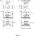
- FIG. 2 shows a more detailed view of MME 106 and AMF 116 in an illustrative embodiment.
- the MME 106 comprises a processor 200 coupled to a memory 202 and interface circuitry 204.
- the processor 200 of the MME 106 includes a secure intersystem mobility processing module 210 that may be implemented at least in part in the form of software executed by the processor.
- the processing module 210 performs operations of the processes described in conjunction with subsequent figures and otherwise herein.
- the memory 202 of the MME 106 includes a secure intersystem mobility storage module 212 that stores data generated or otherwise used during secure intersystem mobility operations.
- the AMF 116 comprises a processor 220 coupled to a memory 222 and interface circuitry 224.
- the processor 220 of the AMF 116 includes a secure intersystem mobility processing module 230 that may be implemented at least in part in the form of software executed by the processor.
- the processing module 230 performs operations described in conjunction with subsequent figures and otherwise herein.
- the memory 222 of the AMF 116 includes a secure intersystem mobility storage module 232 that stores data generated or otherwise used during secure intersystem mobility operations.
- the processors 200 and 220 of the respective MME 106 and AMF 116 may comprise, for example, microprocessors, application-specific integrated circuits (ASICs), digital signal processors (DSPs) or other types of processing devices, as well as portions or combinations of such elements.
- ASICs application-specific integrated circuits
- DSPs digital signal processors
- the memories 202 and 222 of the respective MME 106 and AMF 116 may be used to store one or more software programs that are executed by the respective processors 200 and 220 to implement at least a portion of the functionality described herein. For example, operations and other functionality as described in conjunction with subsequent figures and otherwise herein may be implemented in a straightforward manner using software code executed by processors 200 and 220.
- a given one of the memories 202 or 222 may therefore be viewed as an example of what is more generally referred to herein as a computer program product or still more generally as a processor-readable storage medium that has executable program code embodied therein.
- processor-readable storage media may include disks or other types of magnetic or optical media, in any combination.
- Illustrative embodiments can include articles of manufacture comprising such computer program products or other processor-readable storage media.
- the memory 202 or 222 may more particularly comprise, for example, an electronic random access memory (RAM) such as static RAM (SRAM), dynamic RAM (DRAM) or other types of volatile or non-volatile electronic memory.
- RAM electronic random access memory
- SRAM static RAM
- DRAM dynamic RAM
- the latter may include, for example, non-volatile memories such as flash memory, magnetic RAM (MRAM), phase-change RAM (PC-RAM) or ferroelectric RAM (FRAM).
- MRAM magnetic RAM
- PC-RAM phase-change RAM
- FRAM ferroelectric RAM
- memory as used herein is intended to be broadly construed, and may additionally or alternatively encompass, for example, a read-only memory (ROM), a disk-based memory, or other type of storage device, as well as portions or combinations of such devices.
- the interface circuitries 204 and 224 of the respective MME 106 and AMF 116 illustratively comprise transceivers or other communication hardware or firmware that allows the associated system elements to communicate with one another in the manner described herein.
- MME 106 is configured for communication with AMF 116 and vice-versa via their respective interface circuitries 204 and 224. This communication involves the MME 106 sending data to the AMF 116, and the AMF 116 sending data to the MME 106.
- other network elements may be operatively coupled between MME 106 and AMF 116. That is, the mobility management elements/functions of the two networks can communicate with each other directly, indirectly through one or more intermediate network elements/functions, or some combination of both.
- data as used herein is intended to be construed broadly, so as to encompass any type of information that may be sent between user equipment and a core network via a base station element including, but not limited to, NAS messages, MAC codes, other verification parameters, etc.
- FIG. 2 It is to be appreciated that the particular arrangement of components shown in FIG. 2 is an example only, and numerous alternative configurations may be used in other embodiments.
- the mobility management elements/functions can be configured to incorporate additional or alternative components and to support other communication protocols.
- UE 102 may each also be configured to include components such as a processor, memory and network interface. These elements need not be implemented on separate stand-alone processing platforms, but could instead, for example, represent different functional portions of a single common processing platform.
- a processing platform may additionally comprise at least portions of an eNB/gNB and an associated radio network control function.
- a first scenario (4G to 5G)
- the 4G network is the source network and the 5G network is the target network.
- the UE has a valid 4G NAS security context (as the UE has been registered in the 4G network up to the mobility event), and the UE may have a 5G NAS security context still stored from a previous visit to the 5G network.
- the UE when the UE moves from a 4G network to a 5G network, and the UE still has a 5G NAS security context, then the UE includes two different MAC parameters in the initial NAS message:
- the target network forwards the complete 5G initial NAS message, including the 4G-MAC parameter, but excluding the 5G-MAC parameter, to the 4G source network for further action.
- the UE and the 5G target network map the 5G initial NAS message to a message that has the structure of a 4G Tracking Area Update (TAU) or 4G Attach message.
- the UE then computes the 4G-MAC over the mapped message while the UE computes the 5G-MAC over the entire 5G initial NAS message.
- This mapping could be achieved, e.g., by selecting an appropriate subset of the 5G initial NAS message, or by other means.
- the alternative approach is required for interworking with so-called legacy MMEs in 4G that have not been upgraded to support interworking with 5G. Such legacy MMEs can only handle messages that have the structure of a 4G message. But the alternative approach could also be applied to interworking with MMEs that are not legacy.
- the 4G source network verifies the integrity of the message based on the received 4G-MAC parameter. If the verification is successful, the 4G network generates a key to be used in the target network and sends it to the 5G target network.
- This key could either be a mapped key when the MME has been upgraded to support interworking with 5G, or a K ASME key (as defined in the LTE security specification TS 33.401, the disclosure ofwhich is incorporated by reference by herein in its entirety) when the MME is a legacy MME.
- the 5G target network implies from the response that the message has been verified by the 4G source network and subsequently uses the received key to generate a new set of 5G-NAS keys.
- An existing NAS security mode command procedure is used to complete the key setup in the UE.
- FIGS. 3 and 4 illustrate message flows and network configurations within which one or more of the above-described secure intersystem mobility techniques can be implemented. These message flows and network configurations are understood to be illustrative embodiments.
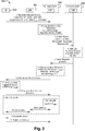
- FIG. 3 illustrates a UE mobility event from a 4G source network to a 5G target network. More particularly, the example in FIG. 3 shows an idle mode mobility event from 4G to 5G.
- the procedure depicts how two MACs are sent in the initial NAS message (Registration Request) and used during the mobility event to verify the UE either in the source network (4G) or in the target network (5G).
- FIG. 3 shows, in procedure 300, UE 302, gNB 304, 5G Target System (AMF) 306, and 4G Source System (MME) 308.
- the numbered steps referred to below correspond to the numbers 1 through 10 in FIG. 3 . It is to be understood that in an idle mode mobility procedure, radio functions such as an eNB and a gNB do not necessarily take an active role.
- step 1 UE 302 initiates a mobility registration update with a Registration Request (RR) message sent to AMF 306 through gNB 304.
- RR Registration Request
- UE 302 includes the mapped 5G-GUTI derived from the 4G-GUTI, and KSI equal to the value of the eKSI associated with the current Evolved Packet System (EPS) security context, and a 32-bit NONCE UE , in the Registration Request message.
- GUTI refers to a Globally Unique Temporary Identity
- KSI is Key Set Identifier.
- the mapped 5G-GUTI has enough information to identity the 4G-GUTI and MME 308.
- UE 302 If the UE 302 has a current 5G NAS security context, then UE 302 integrity-protects the message using this context and includes the 5G-KSI, native 5G-GUTI and 5G-MAC in the Registration Request message. The UE 302 uses the current 5G NAS security context algorithms to generate the 5G-MAC for the Registration Request message.
- the UE 302 additionally integrity-protects the message by generating a 4G-MAC using the current 4G NAS integrity identified by the 4G-GUTI used to derive a mapped 5G-GUTI.
- the 4G-MAC field is used to store the generated 4G-MAC.
- the UE may alternatively compute the 4G-MAC over a message mapped from the entire 5G initial NAS message.
- step 2 if the 5G-GUTI was included in the message along with 5G-KSI, the AMF 306 searches for the already existing UE context stored and, if available, uses it to verify the Registration Request using the 5G-MAC parameter.
- step 3 the AMF 306 uses the mapped 5G-GUTI received from the UE to derive the MME address and sends a Context Request message to the MME 308 to retrieve user information.
- the AMF 306 forwards the complete Registration Request message, or alternatively only the message mapped from the complete Registration Request message, except for the 5G-MAC, but including the "UE validated" field and the 4G GUTI to the MME 308 with the Context Request message. It includes the 4G-MAC and eKSI if and only if the UE 302 could not be validated in step 2 by checking the 5G-MAC.
- the "UE validated" field is used to indicate whether the AMF 306 has validated the integrity protection of the Registration Request based on the native 5G context.
- step 4 if the Registration Request message, or the mapped message, as received by the MME 308, was protected with a 4G MAC, the MME 308 verifies the integrity protection of the Registration Request message, or the mapped message, based on the current 4G security context identified by the eKSI value it received from the AMF 306. If the verification was successful, the MME 308 proceeds to step 5.
- MME 308 responds to the AMF 306 with a Context Response with the UE's security context.
- This message includes K ASME , or a key mapped from K ASME , if Context Request indicated that UE was not validated and 4G-MAC verification was successful. If the Context Response does not include K ASME , or a key mapped from K ASME , proceed to step 8.
- AMF 306 generates a new mapped K AMF using the K ASME key, or the key mapped from K ASME , it obtained from the MME 308, NONCE UE , and NONCE AMF and a 5G NAS security context is derived from the mapped K AMF key including NAS security keys.
- the AMF allocates KSI 4G to identify the mapped K AMF key.
- AMF 306 initiates a NAS Security mode command procedure as described in 3GPP Technical Specification TS 33.501, the disclosure of which is incorporated by reference herein in its entirety, including the KSI 4G , replayed UE Security capabilities, NONCE AMF , NONCE MME and NAS algorithms.
- UE 302 derives a mapped K AMF from its copy of K ASME , or a key mapped from K ASME , in the same way as the AMF did in step 7a. UE 302 further generates a new mapped 5G NAS Security context including NAS security keys from the mapped K AMF .
- step 7c UE 302 responds to the AMF 306 with the NAS Security Mode Complete message.
- step 8 if the AMF 306 shares a current 5G NAS security context with the UE 302 and has successfully validated the UE (from step 2), the AMF 306 proceeds to check if it needs to establish radio bearers. If the AMF 306 wants to change the NAS algorithms, the AMF 306 uses a NAS security mode procedure to inform the UE 302. If the "active flag" is set in the Registration Request message or the AMF 306 choses to establish radio bearers when there is pending downlink UP data or pending downlink signalling, a K gNB derivation is performed from the K AMF key.
- the newly derived K gNB key is delivered to the target gNB on the S1 interface.
- the AS Security context is established between the gNB and the UE.
- AMF 306 sends a Registration Accept message to the UE 302.
- step 10 UE 302 responds with a Registration Complete message to the AMF 306.
- an integrity check happens only once, either in the target AMF 306 in step 2 or in step 4 in the source MME 308. Accordingly, a decision is made in the AMF 306 to either reuse the existing verified UE context or rely on the mapped key derived from the information sent by the source MME 308 to generate a new mapped UE context.
- NAS security mode command procedure is optional if the AMF 308 successfully verified the UE 302 with its own store of the UE security context.
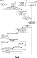
- FIG. 4 illustrates a UE mobility event from a 5G source network to a 4G target network. More particularly, the example in FIG. 4 shows call flow for the mobility scenario from a 5G source system to an upgraded 4G target system using the dual 5G-MAC and 4G-MAC in a tracking area update request.
- FIG. 4 shows, in procedure 400, UE 402, eNB 404, 4G Upgraded Target System (MME) 406, and 5G Source System (AMF) 408.
- MME 4G Upgraded Target System
- AMF 5G Source System
- step 1 UE 402 initiates a TAU (Tracking Area Update) Request message sent to MME 406 through eNB 404.
- TAU Track Area Update
- UE 402 includes the mapped 4G-GUTI derived from the 5G-GUTI, and eKSI equal to the value of the NG-KSI associated with the current 5GS security context, and a 32-bit NONCE UE , in the TAU Request message.
- the mapped 4G-GUTI has enough information to identity the 5G-GUTI and AMF 408.
- UE 402 If the UE 402 has a current 4G NAS security context, then UE 402 integrity-protects the message using this context and includes the eKSI, native 4G-GUTI and 4G-MAC in the TAU Request message. The UE 402 uses the current 4G NAS security context algorithms to generate the 4G-MAC for the TAU Request message.
- the UE 402 additionally integrity-protects the message by generating a 5G-MAC using the current 5G NAS integrity identified by the 5G-GUTI used to derive a mapped 4G-GUTI.
- the 5G-MAC field is used to store the generated 5G-MAC.
- step 2 if the 4G-GUTI was included in the message along with 4G-KSI, the MME 406 searches for the already existing UE context stored and, if available, uses it to verify the TAU Request using the 4G-MAC parameter.
- step 3 the MME 406 uses the mapped 4G-GUTI received from the UE to derive the AMF address and sends a Context Request message to the AMF 408 to retrieve user information.
- the MME 406 forwards the complete TAU Request message, except for the 4G-MAC, but including the "UE validated" field and the 5G GUTI to the AMF 408 with the Context Request message. It includes the 5G-MAC and NG-KSI if and only if the UE 402 could not be validated in step 2 by checking the 4G-MAC.
- the "UE validated" field is used to indicate whether the MME 406 has validated the integrity protection of the TAU Request based on the native 4G context.
- step 4 if the Registration Request message parameters contained in the TAU Request message, as received by the AMF 408, were protected with a 5G MAC, the AMF 408 verifies the integrity protection of the Registration Request message based on the current 5G security context identified by the NG-KSI value it received from the MME 406. If the verification was successful, the AMF 408 proceeds to step 5.
- AMF 408 responds to the MME 406 with a Context Response with the UE's security context.
- This message includes K AMF if Context Request indicated that UE was not validated and 5G-MAC verification was successful. If the Context Response does not include K AMF , proceed to step 8.
- MME 406 generates a new mapped K ASME using the K AMF key it obtained from the AMF 408, NONCE UE , and NONCE AMF and a 4G NAS security context is derived from the mapped K ASME key including NAS security keys.
- the AMF allocates eKSI 5G to identify the mapped K ASME key.
- MME 406 initiates a NAS Security mode command procedure as described in 3GPP Technical Specification TS 33.501, the disclosure of which is incorporated by reference herein in its entirety, including the KSI 4G , replayed UE Security capabilities, NONCE AMF , NONCE MME and NAS algorithms.
- UE 402 derives a mapped K ASME from its copy of K AMF in the same way as the MME did in step 7a. UE 402 further generates a new mapped 4G NAS Security context including NAS security keys from the mapped K ASME .
- step 7c. UE 402 responds to the MME 406 with the NAS Security Mode Complete message.
- step 8 if the MME 406 shares a current 4G NAS security context with the UE 402 and has successfully validated the UE (from step 2), the MME 406 proceeds to check if it needs to establish radio bearers. If the MME 406 wants to change the NAS algorithms, the MME 406 uses a NAS security mode procedure to inform the UE 402. If the "active flag" is set in the TAU Request message or the MME 406 choses to establish radio bearers when there is pending downlink UP data or pending downlink signalling, a K eNB derivation is performed from the K ASME key using the KDF as specified in TS 33.501.
- the newly derived K eNB key is delivered to the target gNB on the S1 interface.
- the AS Security context is established between the eNB and the UE.
- step 9 MME 406 sends a TAU Accept message to the UE 402.
- step 10 UE 402 responds with a TAU Complete message to the MME 406.
- an integrity check happens only once, either in the target MME 406 in step 2 or in step 4 in the source AMF 408. Accordingly, a decision is made in the MME 406 to either reuse the existing verified UE context or rely on the mapped key derived from the information sent by the source AMF 408 to generate a new mapped UE context.
- NAS security mode command procedure is optional if the MME 408 successfully verified the UE 402 with its own store of the UE security context.
- the source mobility management entity may be an unmodified 4G mobility management entity with no awareness of a 5G interworking.
- Such 5G unaware mobility management entities would be able to support interworking and context transfer to a target 5G network AMF, if the 5G target AMF canonically maps the received registration request message from the UE to the 4G equivalent Context request message containing TAU parameters along with the 4G-MAC from the UE.
- the 5G AMF performs this intelligent mapping to the Context Request and the Context response based on its awareness that the source 4G mobility management entity is 5G unaware. With this functionality, a 5G AMF will interwork with a 5G aware MME as well as non-aware MME.
- the embodiments are not limited to the LTE or 5G context and the disclosed techniques can be adapted in a straightforward manner to a wide variety of other communication system contexts including, but not limited to, other 3GPP systems and non-3GPP systems.
- the processor, memory, controller and other components of a user equipment or base station element of a communication system as disclosed herein may include well-known circuitry suitably modified to implement at least a portion of the identity request functionality described above.
- embodiments may be implemented in the form of articles of manufacture each comprising one or more software programs that are executed by processing circuitry of user equipment, base stations or other elements of a communication system.
- Conventional aspects of such circuitry are well known to those skilled in the art and therefore will not be described in detail herein.
- embodiments may be implemented in one or more ASICS, FPGAs or other types of integrated circuit devices, in any combination.
- Such integrated circuit devices, as well as portions or combinations thereof, are examples of "circuitry" as that term is used herein.
- a wide variety of other arrangements of hardware and associated software or firmware may be used in implementing the illustrative embodiments.
Landscapes
- Engineering & Computer Science (AREA)
- Computer Security & Cryptography (AREA)
- Computer Networks & Wireless Communication (AREA)
- Signal Processing (AREA)
- Power Engineering (AREA)
- Computer Hardware Design (AREA)
- Computing Systems (AREA)
- General Engineering & Computer Science (AREA)
- Databases & Information Systems (AREA)
- Mobile Radio Communication Systems (AREA)
- Selective Calling Equipment (AREA)
- Data Exchanges In Wide-Area Networks (AREA)
Abstract
Description
- The field relates generally to communication systems, and more particularly, but not exclusively, to security within such systems.
- This section introduces aspects that may be helpful to facilitating a better understanding of the inventions. Accordingly, the statements of this section are to be read in this light and are not to be understood as admissions about what is in the prior art or what is not in the prior art.
- Fourth generation (4G) wireless mobile telecommunications technology, also known as Long Term Evolution (LTE) technology, was designed to provide high capacity mobile multimedia with high data rates particularly for human interaction. Next generation or fifth generation (5G) technology is intended to be used not only for human interaction, but also for machine type communications in so-called Internet of Things (IoT) networks.
- While 5G networks are intended to enable massive IoT services (e.g., very large numbers of limited capacity devices) and mission-critical IoT services (e.g., requiring high reliability), improvements over legacy mobile communication services are supported in the form of enhanced mobile broadband (eMBB) services intended to provide improved wireless Internet access for mobile devices.
- Security during mobility of user equipment or UE (such as, for example, a mobile terminal or subscriber) between two networks (i.e., intersystem mobility) is an important consideration. For example, initial Non-Access Stratum (NAS) messages, e.g., registration messages, between the UE and a network are integrity protected by the UE if there is a current NAS security context in the UE that is valid and accepted by the network.
- Today, in the scenario where the UE is moving between networks, e.g., interworking between a 4G network and 5G network, adequate integrity verification is not yet defined.
- Illustrative embodiments provide improved techniques for secure intersystem mobility of user equipment in a communication system environment.
- In one or more methods according to illustrative embodiments, in accordance with the occurrence of a mobility event whereby user equipment moves from accessing a source network to accessing a target network in a communication system environment, the user equipment sends a control plane message to the target network comprising an integrity verification parameter associated with the source network and an integrity verification parameter associated with the target network.
- In another illustrative embodiment, in accordance with the occurrence of a mobility event whereby user equipment moves from accessing a source network to accessing a target network in a communication system environment, a mobility management element of the target network receives a control plane message from the user equipment comprising an integrity verification parameter associated with the source network and an integrity verification parameter associated with the target network.
- In a further embodiment, in accordance with the occurrence of a mobility event whereby user equipment moves from accessing a source network to accessing a target network in a communication system environment, a mobility management element of the source network receives a context request message from a mobility management element of the target network when the mobility management element of the target network is unable to verify the user equipment based on a control plane message received from the user equipment comprising an integrity verification parameter associated with the source network and an integrity verification parameter associated with the target network.
- Advantageously, by providing integrity verification parameters for both the source network and the target network in a control plane message sent by the user equipment to the mobility management element of the target network (e.g., a Registration Request message in 5G and a Tracking Area Update message in 4G), the mobility management element of the target network does not have to initiate a new Authentication and Key Agreement (AKA) run and thus, among other benefits, avoids performance degradation. Rather, the target network can verify the user equipment on its own or seek the assistance of the source network.
- Further embodiments are provided in the form of non-transitory computer-readable storage medium having embodied therein executable program code that when executed by a processor causes the processor to perform the above steps. Still further embodiments comprise apparatus with a processor and a memory configured to perform the above steps.
- These and other features and advantages of embodiments described herein will become more apparent from the accompanying drawings and the following detailed description.
-
-
FIG. 1 shows a block diagram of a communication system environment in an illustrative embodiment. -
FIG. 2 shows a more detailed view of network elements/functions in an illustrative embodiment. -
FIG. 3 shows a message flow for a secure intersystem mobility procedure in an illustrative embodiment. -
FIG. 4 shows a message flow for a secure intersystem mobility procedure in another illustrative embodiment. - Embodiments will be illustrated herein in conjunction with example communication systems and associated techniques for providing security for user equipment during intersystem mobility that, among other benefits, avoids performance degradation of the core network. It should be understood, however, that the scope of the claims is not limited to particular types of communication systems and/or processes disclosed. Embodiments can be implemented in a wide variety of other types of communication systems, using alternative processes and operations. For example, although illustrated in the context of wireless cellular systems utilizing 3GPP system elements such as an LTE Evolved Packet Core (4G) and a 3GPP next generation system (5G), the disclosed embodiments can be adapted in a straightforward manner to a variety of other types of communication systems including, but not limited to, WiMAX systems and Wi-Fi systems.
- In existing systems, a single Message Authentication Code (MAC) parameter is used to integrity protect the NAS message sent to a network. In the case of a mobility event (active mode mobility, i.e., handover, or idle mode mobility) from a source network to a target network, an initial NAS message is sent to the target network to trigger the mobility event. If the UE still has a valid security context for the target network, it will integrity-protect the NAS message using this security context and use the MAC parameter to send the generated MAC code to the target network. In existing approaches, the NAS-MAC parameter is a common parameter that either contains the authentication code to be verified by the source network or by the target network. This is no problem as long as source and target networks are both of the same type, say they are both LTE networks. It becomes a problem, however, when the source and target networks are of different types, say the source network is an LTE network and the target network is a 5G network; the problem is that the MACs used in LTE are (very likely) different from those that will be used in 5G. However, there exists no mechanism today for the UE to send two independent MACs for both the source and the target networks to verify integrity of the message, if required.
- Thus, a problem with the current mechanism is that the UE does not know before-hand whether the initial integrity-protected message it sent to the target network can be successfully verified by the target network. It is possible that the target network has deleted the corresponding "native" security context for the UE. In such a scenario, there is no way for the target network to verify the message. In addition, the target network cannot rely on the source network to verify the message because there is no other field to carry the second MAC to be verified by the source network.
- The only logical action for the target network would be to re-authenticate the UE again by executing a fresh Authentication and Key Agreement (AKA) run and then generate NAS and AS (Access Stratum) security keys through relevant procedures. Re-authentication has, however, a significant negative performance impact, so solutions that can avoid this would be preferred.
- As illustratively used herein, Non-Access Stratum (NAS) is a functional layer of a communication network that provides non-radio signaling for certain control plane functionalities between the UE and a Core Network (CN), transparent to the Radio Access Network (RAN). Such functionalities include, but are not limited to, mobility management, authentication, etc. Compare the NAS functional layer to the Access Stratum (AS), which is the functional layer below NAS that provides functionalities between the UE and the RAN including, but not limited to, data transport over a wireless connection and radio resource management.
- Illustrative embodiments provide improved techniques for intersystem mobility scenarios. More specifically, in one embodiment, a parameter is provided in the initial NAS message in 5G to carry an additional 4G-MAC for verification by the source network, if required. In another embodiment, similarly, both 4G and 5G verification parameters are provided when the UE is moving from the 5G network to the 4G network.
- Before describing interworking scenarios with mobility from 4G to 5G, and from 5G to 4G, an exemplary communication system environment in which such illustrative embodiments are implemented is described in the context of
FIGS. 1 and2 . - 5G security aspects are addressed in 5G Technical Report (TR) 33.899, V1.1.0, entitled "3rd Generation Partnership Project; Technical Specification Group Services and System Aspects; Study on the security aspects of the next generation system (Release 14),", and in TS 33.501, v0.3.0, "Security Architecture and Procedures for 5G System," the disclosures of which are incorporated by reference herein in their entireties. Of particular interest are scenarios where the UE is moving from accessing a 5G network to accessing a 4G network, and in the converse, moving from accessing a 4G network to accessing a 5G network. Such movement between different generation communication networks is generally referred to herein as "intersystem mobility." In addition to security concerns, of course, performance degradation is also a concern for such networks, i.e., in the context of avoiding additional processing overhead when possible.
-
FIG. 1 shows acommunication system environment 100 within which illustrative embodiments are implemented. More particularly,communication system environment 100 shows part of (P/O) a 4G network and part of a 5G network. It is assumed that a UE 102 is involved in a mobility event (active mode mobility, i.e., handover, or idle mode mobility) from a source network (i.e., from one of the 4G network and the 5G network) to a target network (i.e., to the other of the 4G network and 5G network). It is to be understood that the elements shown incommunication system environment 100 are intended to represent main functions provided within the system, e.g., UE access functions and mobility management functions. As such, the blocks shown inFIG. 1 reference specific elements in LTE and 5G networks that provide the main functions. However, other network elements may be used to implement some or all of the main functions represented. Also, it is to be understood that not all functions of an LTE or 5G network are depicted inFIG. 1 . Rather, functions that facilitate an explanation of illustrative embodiments are represented. - Accordingly, as shown in
FIG. 1 ,communication system environment 100 comprises user equipment (UE) 102 that communicates via anair interface 103 with an access point (e.g., evolved Node B or eNB in a 4G network) 104 in the part of the 4G network shown inFIG. 1 . The UE 102 may be a mobile station, and such a mobile station may comprise, by way of example, a mobile telephone, a computer, or any other type of communication device. The term "user equipment" as used herein is therefore intended to be construed broadly, so as to encompass a variety of different types of mobile stations, subscriber stations or, more generally, communication devices, including examples such as a combination of a data card inserted in a laptop or other equipment. Such communication devices are also intended to encompass devices commonly referred to as access terminals. - In one embodiment,
UE 102 is comprised of a Universal Integrated Circuit Card (UICC) and a Mobile Equipment (ME). The UICC is the user-dependent part of the UE and contains at least one Universal Subscriber Identity Module (USIM) and appropriate application software. The USIM securely stores the International Mobile Subscriber Identity (IMSI) number and its related key which are used to identify and authenticate subscribers to access networks. The ME is the user-independent part of the UE and contains terminal equipment (TE) functions and various mobile termination (MT) functions. - The
access point 104 is illustratively part of an access network of the 4G network. Such an access network may comprise a plurality of base stations. The base stations may be logically separate entities, but in a given embodiment may be implemented in the same physical network element, such as, for example, a base station router or femto cellular access point. In an LTE (4G) network, the access network is an Evolved Universal Terrestrial Radio Access Network (E-UTRAN). In general, the access point provides access for the UE to a Core Network (CN), which then provides access for the UE to other UEs and/or a data network such as a packet data network (e.g., Internet). - The
access point 104 in this illustrative embodiment is operatively coupled to amobility management function 106. In a 4G network, the function is typically implemented by a Mobility Management Entity (MME). A mobility management function, as used herein, is the element or function in the CN part of the communication system that manages, among other network operations, access and authentication operations with the UE (through the access point 104). - Similarly, in the 5G network as shown in
FIG. 1 , theUE 102 may alternatively communicate via anair interface 113 with an access point (e.g., gNB in a 5G network) 114. For example, the 5G System is described in 5G Technical Specification (TS) 23.501, V0.4.0, entitled "Technical Specification Group Services and System Aspects; System Architecture for the 5G System," the disclosure of which is incorporated by reference herein in its entirety. - The
access point 114 in this illustrative embodiment is operatively coupled to amobility management function 116. In a 5G network, the function is implemented by an Access and Mobility Management Function (AMF). Although not expressly shown, a Security Anchor Function (SEAF) can be implemented with the AMF connecting a UE with the mobility management. Thus, KSEAF in 5G would take over the role of the Access Security Management Entity Key (KASME) in LTE. - It is to be appreciated that this particular arrangement of system elements in
FIG. 1 is an example only, and other types and arrangements of additional or alternative elements can be used to implement a communication system in other embodiments. For example, in other embodiments, thesystem environment 100 may comprise authentication elements, gateway elements, as well as other elements not expressly shown herein. - Accordingly, the
FIG. 1 arrangement is just one example configuration of a wireless cellular system environment, and numerous alternative configurations of system elements may be used. For example, although only single UE, eNB/gNB, and MME/AMF elements are shown in theFIG. 1 embodiment, this is for simplicity and clarity of description only. A given alternative embodiment may of course include larger numbers of such system elements, as well as additional or alternative elements of a type commonly associated with conventional system implementations. - It is also to be noted that while
FIG. 1 illustrates system elements as singular functional blocks, the various subnetworks that make up the 5G network are partitioned into so-called network slices. Network slices (network partitions) comprise a series of function sets (i.e., function chains) for each corresponding service type using network function virtualization (NFV) on a common physical infrastructure. The network slices are instantiated as needed for a given service, e.g., eMBB service, massive IoT service, and mission-critical IoT service. A network slice or function is thus instantiated when an instance of that network slice or function is created. In some embodiments, this involves installing or otherwise running the network slice or function on one or more host devices of the underlying physical infrastructure.UE 102 is configured to access one or more of these services viagNB 114. -
FIG. 2 shows a more detailed view ofMME 106 andAMF 116 in an illustrative embodiment. TheMME 106 comprises aprocessor 200 coupled to amemory 202 andinterface circuitry 204. Theprocessor 200 of theMME 106 includes a secure intersystemmobility processing module 210 that may be implemented at least in part in the form of software executed by the processor. Theprocessing module 210 performs operations of the processes described in conjunction with subsequent figures and otherwise herein. Thememory 202 of theMME 106 includes a secure intersystemmobility storage module 212 that stores data generated or otherwise used during secure intersystem mobility operations. - The
AMF 116 comprises aprocessor 220 coupled to amemory 222 andinterface circuitry 224. Theprocessor 220 of theAMF 116 includes a secure intersystemmobility processing module 230 that may be implemented at least in part in the form of software executed by the processor. Theprocessing module 230 performs operations described in conjunction with subsequent figures and otherwise herein. Thememory 222 of theAMF 116 includes a secure intersystemmobility storage module 232 that stores data generated or otherwise used during secure intersystem mobility operations. - The
processors respective MME 106 andAMF 116 may comprise, for example, microprocessors, application-specific integrated circuits (ASICs), digital signal processors (DSPs) or other types of processing devices, as well as portions or combinations of such elements. - The
memories respective MME 106 andAMF 116 may be used to store one or more software programs that are executed by therespective processors processors - A given one of the
memories - The
memory - The
interface circuitries respective MME 106 andAMF 116 illustratively comprise transceivers or other communication hardware or firmware that allows the associated system elements to communicate with one another in the manner described herein. - It is apparent from
FIG. 2 thatMME 106 is configured for communication withAMF 116 and vice-versa via theirrespective interface circuitries MME 106 sending data to theAMF 116, and theAMF 116 sending data to theMME 106. However, in alternative embodiments, other network elements may be operatively coupled betweenMME 106 andAMF 116. That is, the mobility management elements/functions of the two networks can communicate with each other directly, indirectly through one or more intermediate network elements/functions, or some combination of both. The term "data" as used herein is intended to be construed broadly, so as to encompass any type of information that may be sent between user equipment and a core network via a base station element including, but not limited to, NAS messages, MAC codes, other verification parameters, etc. - It is to be appreciated that the particular arrangement of components shown in
FIG. 2 is an example only, and numerous alternative configurations may be used in other embodiments. For example, the mobility management elements/functions can be configured to incorporate additional or alternative components and to support other communication protocols. - Other system elements, such as
UE 102,eNB 104, andgNB 114, may each also be configured to include components such as a processor, memory and network interface. These elements need not be implemented on separate stand-alone processing platforms, but could instead, for example, represent different functional portions of a single common processing platform. Such a processing platform may additionally comprise at least portions of an eNB/gNB and an associated radio network control function. - Before describing message flows associated with embodiments of the secure intersystem mobility procedures, interworking scenarios with mobility from a 4G network to a 5G network are described, followed by interworking scenarios with mobility from a 5G network to a 4G network.
- In a first scenario (4G to 5G), assume that the 4G network is the source network and the 5G network is the target network. The UE has a valid 4G NAS security context (as the UE has been registered in the 4G network up to the mobility event), and the UE may have a 5G NAS security context still stored from a previous visit to the 5G network.
- According to illustrative embodiments, when the UE moves from a 4G network to a 5G network, and the UE still has a 5G NAS security context, then the UE includes two different MAC parameters in the initial NAS message:
- (i) a MAC generated according to 5G specifications ('5G-MAC') using the 5G NAS security context available by assumption; and
- (ii) a MAC generated according to 4G specifications ('4G-MAC') using the 4G NAS security context available from having been registered in the 4G source network.
- If the 5G target network does not possess the corresponding 5G NAS security context for the UE and therefore cannot verify the message, the target network forwards the complete 5G initial NAS message, including the 4G-MAC parameter, but excluding the 5G-MAC parameter, to the 4G source network for further action.
- In an alternative approach, the UE and the 5G target network map the 5G initial NAS message to a message that has the structure of a 4G Tracking Area Update (TAU) or 4G Attach message. The UE then computes the 4G-MAC over the mapped message while the UE computes the 5G-MAC over the entire 5G initial NAS message. This mapping could be achieved, e.g., by selecting an appropriate subset of the 5G initial NAS message, or by other means. The alternative approach is required for interworking with so-called legacy MMEs in 4G that have not been upgraded to support interworking with 5G. Such legacy MMEs can only handle messages that have the structure of a 4G message. But the alternative approach could also be applied to interworking with MMEs that are not legacy.
- The 4G source network verifies the integrity of the message based on the received 4G-MAC parameter. If the verification is successful, the 4G network generates a key to be used in the target network and sends it to the 5G target network. This key could either be a mapped key when the MME has been upgraded to support interworking with 5G, or a KASME key (as defined in the LTE security specification TS 33.401, the disclosure ofwhich is incorporated by reference by herein in its entirety) when the MME is a legacy MME.
- The 5G target network implies from the response that the message has been verified by the 4G source network and subsequently uses the received key to generate a new set of 5G-NAS keys. An existing NAS security mode command procedure is used to complete the key setup in the UE.
- In a second scenario (5G to 4G), assume that the MME in the
target 4G network has been upgraded to support interworking with 5G networks. Recall from above, that according to illustrative embodiments, two different MAC parameters, a 4G-MAC and a 5G-MAC, are sent in the initial NAS message by the UE. It is further assumed the MME in the 4G network has been upgraded to support interworking with 5G networks and understands the purpose of the two different MAC parameters. -
FIGS. 3 and4 illustrate message flows and network configurations within which one or more of the above-described secure intersystem mobility techniques can be implemented. These message flows and network configurations are understood to be illustrative embodiments. -
FIG. 3 illustrates a UE mobility event from a 4G source network to a 5G target network. More particularly, the example inFIG. 3 shows an idle mode mobility event from 4G to 5G. The procedure depicts how two MACs are sent in the initial NAS message (Registration Request) and used during the mobility event to verify the UE either in the source network (4G) or in the target network (5G).FIG. 3 shows, inprocedure 300,UE 302,gNB numbers 1 through 10 inFIG. 3 . It is to be understood that in an idle mode mobility procedure, radio functions such as an eNB and a gNB do not necessarily take an active role. - In
step 1,UE 302 initiates a mobility registration update with a Registration Request (RR) message sent toAMF 306 throughgNB 304. - As shown,
UE 302 includes the mapped 5G-GUTI derived from the 4G-GUTI, and KSI equal to the value of the eKSI associated with the current Evolved Packet System (EPS) security context, and a 32-bit NONCEUE, in the Registration Request message. As is known, GUTI refers to a Globally Unique Temporary Identity, and KSI is Key Set Identifier. - The mapped 5G-GUTI has enough information to identity the 4G-GUTI and
MME 308. - If the
UE 302 has a current 5G NAS security context, thenUE 302 integrity-protects the message using this context and includes the 5G-KSI, native 5G-GUTI and 5G-MAC in the Registration Request message. TheUE 302 uses the current 5G NAS security context algorithms to generate the 5G-MAC for the Registration Request message. - The
UE 302 additionally integrity-protects the message by generating a 4G-MAC using the current 4G NAS integrity identified by the 4G-GUTI used to derive a mapped 5G-GUTI. The 4G-MAC field is used to store the generated 4G-MAC. As indicated for an alternative embodiment above, the UE may alternatively compute the 4G-MAC over a message mapped from the entire 5G initial NAS message. - In
step 2, if the 5G-GUTI was included in the message along with 5G-KSI, theAMF 306 searches for the already existing UE context stored and, if available, uses it to verify the Registration Request using the 5G-MAC parameter. - In
step 3, theAMF 306 uses the mapped 5G-GUTI received from the UE to derive the MME address and sends a Context Request message to theMME 308 to retrieve user information. - The
AMF 306 forwards the complete Registration Request message, or alternatively only the message mapped from the complete Registration Request message, except for the 5G-MAC, but including the "UE validated" field and the 4G GUTI to theMME 308 with the Context Request message. It includes the 4G-MAC and eKSI if and only if theUE 302 could not be validated instep 2 by checking the 5G-MAC. The "UE validated" field is used to indicate whether theAMF 306 has validated the integrity protection of the Registration Request based on the native 5G context. - In
step 4, if the Registration Request message, or the mapped message, as received by theMME 308, was protected with a 4G MAC, theMME 308 verifies the integrity protection of the Registration Request message, or the mapped message, based on the current 4G security context identified by the eKSI value it received from theAMF 306. If the verification was successful, theMME 308 proceeds to step 5. - In
step 5,MME 308 responds to theAMF 306 with a Context Response with the UE's security context. This message includes KASME, or a key mapped from KASME, if Context Request indicated that UE was not validated and 4G-MAC verification was successful. If the Context Response does not include KASME, or a key mapped from KASME, proceed to step 8. - In step 6,
AMF 306 generates a new mapped KAMF using the KASME key, or the key mapped from KASME, it obtained from theMME 308, NONCEUE, and NONCEAMF and a 5G NAS security context is derived from the mapped KAMF key including NAS security keys. The AMF allocates KSI4G to identify the mapped KAMF key. - In step 7a.,
AMF 306 initiates a NAS Security mode command procedure as described in 3GPP Technical Specification TS 33.501, the disclosure of which is incorporated by reference herein in its entirety, including the KSI4G, replayed UE Security capabilities, NONCEAMF, NONCEMME and NAS algorithms. - In step 7b.,
UE 302 derives a mapped KAMF from its copy of KASME, or a key mapped from KASME, in the same way as the AMF did instep 7a.UE 302 further generates a new mapped 5G NAS Security context including NAS security keys from the mapped KAMF. - In step 7c.,
UE 302 responds to theAMF 306 with the NAS Security Mode Complete message. - In
step 8, if theAMF 306 shares a current 5G NAS security context with theUE 302 and has successfully validated the UE (from step 2), theAMF 306 proceeds to check if it needs to establish radio bearers. If theAMF 306 wants to change the NAS algorithms, theAMF 306 uses a NAS security mode procedure to inform theUE 302. If the "active flag" is set in the Registration Request message or theAMF 306 choses to establish radio bearers when there is pending downlink UP data or pending downlink signalling, a KgNB derivation is performed from the KAMF key. - The newly derived KgNB key is delivered to the target gNB on the S1 interface. The AS Security context is established between the gNB and the UE.
- In
step 9,AMF 306 sends a Registration Accept message to theUE 302. - In
step 10,UE 302 responds with a Registration Complete message to theAMF 306. - As illustrated in the above procedure, an integrity check happens only once, either in the
target AMF 306 instep 2 or instep 4 in thesource MME 308. Accordingly, a decision is made in theAMF 306 to either reuse the existing verified UE context or rely on the mapped key derived from the information sent by thesource MME 308 to generate a new mapped UE context. NAS security mode command procedure is optional if theAMF 308 successfully verified theUE 302 with its own store of the UE security context. -
FIG. 4 illustrates a UE mobility event from a 5G source network to a 4G target network. More particularly, the example inFIG. 4 shows call flow for the mobility scenario from a 5G source system to an upgraded 4G target system using the dual 5G-MAC and 4G-MAC in a tracking area update request.FIG. 4 shows, inprocedure 400,UE 402,eNB numbers 1 through 10 inFIG. 4 . - In
step 1,UE 402 initiates a TAU (Tracking Area Update) Request message sent toMME 406 througheNB 404. - As shown,
UE 402 includes the mapped 4G-GUTI derived from the 5G-GUTI, and eKSI equal to the value of the NG-KSI associated with the current 5GS security context, and a 32-bit NONCEUE, in the TAU Request message. - The mapped 4G-GUTI has enough information to identity the 5G-GUTI and
AMF 408. - If the
UE 402 has a current 4G NAS security context, thenUE 402 integrity-protects the message using this context and includes the eKSI, native 4G-GUTI and 4G-MAC in the TAU Request message. TheUE 402 uses the current 4G NAS security context algorithms to generate the 4G-MAC for the TAU Request message. - The
UE 402 additionally integrity-protects the message by generating a 5G-MAC using the current 5G NAS integrity identified by the 5G-GUTI used to derive a mapped 4G-GUTI. The 5G-MAC field is used to store the generated 5G-MAC. - In
step 2, if the 4G-GUTI was included in the message along with 4G-KSI, theMME 406 searches for the already existing UE context stored and, if available, uses it to verify the TAU Request using the 4G-MAC parameter. - In
step 3, theMME 406 uses the mapped 4G-GUTI received from the UE to derive the AMF address and sends a Context Request message to theAMF 408 to retrieve user information. - The
MME 406 forwards the complete TAU Request message, except for the 4G-MAC, but including the "UE validated" field and the 5G GUTI to theAMF 408 with the Context Request message. It includes the 5G-MAC and NG-KSI if and only if theUE 402 could not be validated instep 2 by checking the 4G-MAC. The "UE validated" field is used to indicate whether theMME 406 has validated the integrity protection of the TAU Request based on the native 4G context. - In
step 4, if the Registration Request message parameters contained in the TAU Request message, as received by theAMF 408, were protected with a 5G MAC, theAMF 408 verifies the integrity protection of the Registration Request message based on the current 5G security context identified by the NG-KSI value it received from theMME 406. If the verification was successful, theAMF 408 proceeds to step 5. - In
step 5,AMF 408 responds to theMME 406 with a Context Response with the UE's security context. This message includes KAMF if Context Request indicated that UE was not validated and 5G-MAC verification was successful. If the Context Response does not include KAMF, proceed to step 8. - In step 6,
MME 406 generates a new mapped KASME using the KAMF key it obtained from theAMF 408, NONCEUE, and NONCEAMF and a 4G NAS security context is derived from the mapped KASME key including NAS security keys. The AMF allocates eKSI5G to identify the mapped KASME key. - In step 7a.,
MME 406 initiates a NAS Security mode command procedure as described in 3GPP Technical Specification TS 33.501, the disclosure of which is incorporated by reference herein in its entirety, including the KSI4G, replayed UE Security capabilities, NONCEAMF, NONCEMME and NAS algorithms. - In step 7b.,
UE 402 derives a mapped KASME from its copy of KAMF in the same way as the MME did instep 7a.UE 402 further generates a new mapped 4G NAS Security context including NAS security keys from the mapped KASME. - In step 7c.,
UE 402 responds to theMME 406 with the NAS Security Mode Complete message. - In
step 8, if theMME 406 shares a current 4G NAS security context with theUE 402 and has successfully validated the UE (from step 2), theMME 406 proceeds to check if it needs to establish radio bearers. If theMME 406 wants to change the NAS algorithms, theMME 406 uses a NAS security mode procedure to inform theUE 402. If the "active flag" is set in the TAU Request message or theMME 406 choses to establish radio bearers when there is pending downlink UP data or pending downlink signalling, a KeNB derivation is performed from the KASME key using the KDF as specified in TS 33.501. - The newly derived KeNB key is delivered to the target gNB on the S1 interface. The AS Security context is established between the eNB and the UE.
- In
step 9,MME 406 sends a TAU Accept message to theUE 402. - In
step 10,UE 402 responds with a TAU Complete message to theMME 406. - As illustrated in the above procedure, an integrity check happens only once, either in the
target MME 406 instep 2 or instep 4 in thesource AMF 408. Accordingly, a decision is made in theMME 406 to either reuse the existing verified UE context or rely on the mapped key derived from the information sent by thesource AMF 408 to generate a new mapped UE context. NAS security mode command procedure is optional if theMME 408 successfully verified theUE 402 with its own store of the UE security context. - In yet another embodiment, the source mobility management entity may be an unmodified 4G mobility management entity with no awareness of a 5G interworking. Such 5G unaware mobility management entities would be able to support interworking and context transfer to a
target 5G network AMF, if the 5G target AMF canonically maps the received registration request message from the UE to the 4G equivalent Context request message containing TAU parameters along with the 4G-MAC from the UE. The 5G AMF performs this intelligent mapping to the Context Request and the Context response based on its awareness that thesource 4G mobility management entity is 5G unaware. With this functionality, a 5G AMF will interwork with a 5G aware MME as well as non-aware MME. - It is to be appreciated that the naming of identifiers and parameters mentioned herein are for illustrative purposes only. That is, an identifier or parameter may have different names or acronyms in different protocols and standards for different communication network technologies. As such, none of the specific names or acronyms given to these identifiers herein are intended to limit embodiments in any manner.
- As indicated previously, the embodiments are not limited to the LTE or 5G context and the disclosed techniques can be adapted in a straightforward manner to a wide variety of other communication system contexts including, but not limited to, other 3GPP systems and non-3GPP systems.
- The processor, memory, controller and other components of a user equipment or base station element of a communication system as disclosed herein may include well-known circuitry suitably modified to implement at least a portion of the identity request functionality described above.
- As mentioned above, embodiments may be implemented in the form of articles of manufacture each comprising one or more software programs that are executed by processing circuitry of user equipment, base stations or other elements of a communication system. Conventional aspects of such circuitry are well known to those skilled in the art and therefore will not be described in detail herein. Also, embodiments may be implemented in one or more ASICS, FPGAs or other types of integrated circuit devices, in any combination. Such integrated circuit devices, as well as portions or combinations thereof, are examples of "circuitry" as that term is used herein. A wide variety of other arrangements of hardware and associated software or firmware may be used in implementing the illustrative embodiments.
- It should therefore again be emphasized that the various embodiments described herein are presented by way of illustrative example only, and should not be construed as limiting the scope of the claims. For example, alternative embodiments can utilize different communication system configurations, user equipment configurations, base station configurations, network element/function configurations, processes, messaging protocols and message formats than those described above in the context of the illustrative embodiments. These and numerous other alternative embodiments within the scope of the appended claims will be readily apparent to those skilled in the art.
Claims (16)
- A method comprising:in accordance with the occurrence of a mobility event whereby user equipment moves from accessing a source network to accessing a target network in a communication system environment, the user equipment sending a control plane message to the target network comprising an integrity verification parameter associated with the source network and an integrity verification parameter associated with the target network.
- The method of claim 1, wherein the user equipment stores: (i) a security context currently established with the source network; and (ii) a security context previously established with the target network.
- The method of claim 2, wherein the user equipment integrity protects the control plane message using the security context previously established with the target network.
- The method of claim 3, wherein the user equipment additionally integrity protects the control plane message using the security context currently established with the source network.
- The method of claim 3, wherein the user equipment maps the control plane message to another message in the format of a message in the source network and then additionally integrity protects the mapped message using the security context currently established with the source network.
- The method of claim 2, where the registration message further comprises a temporary identifier of the user equipment associated with the target network and a key set indicator associated with the target network.
- The method of claim 2, wherein the integrity verification parameter associated with the source network is a message authentication code generated using the security context currently established with the source network.
- The method of claim 2, wherein the integrity verification parameter associated with the target network is a message authentication code generated using the security context previously established with the target network.
- A method comprising:in accordance with the occurrence of a mobility event whereby user equipment moves from accessing a source network to accessing a target network in a communication system environment, a mobility management element of the target network receiving a control plane message from the user equipment comprising an integrity verification parameter associated with the source network and an integrity verification parameter associated with the target network.
- The method of claim 9, wherein the mobility management element of the target network verifies the user equipment using the control plane message when the mobility management element of the target network maintains the security context previously established with the user equipment.
- The method of claim 10, wherein, when the mobility management element of the target network is not able to verify the user equipment, the mobility management element of the target network sends a context request message to a mobility management element of the source network to verify the user equipment.
- The method of claim 10, wherein, the mobility management element of the target network canonically maps the control plane message to a source network equivalent context request message along with the integrity verification parameter when the mobility management element of the source network is not updated for target network awareness to verify the user equipment.
- The method of claim 11, wherein the mobility management element of the target network receives a context response message from the mobility management element of the source network when the mobility management element of the source network verifies the user equipment using a security context currently established with the user equipment.
- A method comprising:in accordance with the occurrence of a mobility event whereby user equipment moves from accessing a source network to accessing a target network in a communication system environment, a mobility management element of the source network receiving a context request message from a mobility management element of the target network when the mobility management element of the target network is unable to verify the user equipment based on a control plane message received from the user equipment comprising an integrity verification parameter associated with the source network and an integrity verification parameter associated with the target network.
- The method of claim 14, wherein the mobility management element of the source network verifies the user equipment using a security context currently established with the user equipment.
- The method of claim 15, wherein the mobility management element of the source network sends a context response message to the mobility management element of the target network to enable the mobility management element of the target network to initiate establishment of a new security context with the user equipment.
Applications Claiming Priority (1)
| Application Number | Priority Date | Filing Date | Title |
|---|---|---|---|
| IN201741034678 | 2017-09-29 |
Publications (2)
| Publication Number | Publication Date |
|---|---|
| EP3462760A1 true EP3462760A1 (en) | 2019-04-03 |
| EP3462760B1 EP3462760B1 (en) | 2025-07-23 |
Family
ID=63722145
Family Applications (1)
| Application Number | Title | Priority Date | Filing Date |
|---|---|---|---|
| EP18195844.8A Active EP3462760B1 (en) | 2017-09-29 | 2018-09-21 | Security and integrity in intersystem mobility |
Country Status (8)
| Country | Link |
|---|---|
| US (1) | US10512005B2 (en) |
| EP (1) | EP3462760B1 (en) |
| JP (2) | JP6683784B2 (en) |
| KR (2) | KR102148365B1 (en) |
| CN (1) | CN109587688B (en) |
| MY (1) | MY193642A (en) |
| PH (1) | PH12018000291B1 (en) |
| SG (1) | SG10201808530XA (en) |
Cited By (2)
| Publication number | Priority date | Publication date | Assignee | Title |
|---|---|---|---|---|
| EP3796696A4 (en) * | 2019-05-31 | 2022-01-12 | Honor Device Co., Ltd. | METHOD AND APPARATUS FOR ACQUIRING A SECURITY CONTEXT, AND COMMUNICATION SYSTEM |
| CN115885540A (en) * | 2021-07-29 | 2023-03-31 | 华为技术有限公司 | Communication method, device and equipment |
Families Citing this family (17)
| Publication number | Priority date | Publication date | Assignee | Title |
|---|---|---|---|---|
| CN111328457B (en) | 2017-09-15 | 2022-01-28 | 瑞典爱立信有限公司 | Security context in a wireless communication system |
| CN111164994A (en) * | 2018-01-11 | 2020-05-15 | Oppo广东移动通信有限公司 | Positioning method, terminal device and positioning management functional entity in multi-connection network |
| CN110099382B (en) * | 2018-01-30 | 2020-12-18 | 华为技术有限公司 | A message protection method and device |
| PL3756373T3 (en) * | 2018-02-19 | 2022-01-03 | Telefonaktiebolaget Lm Ericsson (Publ) | Support for collaboration and / or mobility between different wireless communication systems |
| CN112567807B (en) | 2018-06-04 | 2023-07-21 | 瑞典爱立信有限公司 | Core network indication and security handling for handover |
| US20200322795A1 (en) * | 2019-04-03 | 2020-10-08 | Mediatek Singapore Pte. Ltd. | Apparatuses and methods for alignment of common non access stratum (nas) security context |
| CN111866974B (en) * | 2019-04-29 | 2022-12-06 | 华为技术有限公司 | Method and apparatus for mobile registration |
| CN113994763B (en) * | 2019-06-12 | 2024-11-12 | 瑞典爱立信有限公司 | Handling UE in CM-CONNECTED state and RRC inactive state |
| CN112087297B (en) * | 2019-06-14 | 2022-05-24 | 华为技术有限公司 | Method, system and equipment for obtaining security context |
| CN112153647B (en) * | 2019-06-29 | 2022-04-22 | 华为技术有限公司 | Communication method and related equipment |
| WO2021030946A1 (en) * | 2019-08-16 | 2021-02-25 | Zte Corporation | A method of registration with access and mobility management function re-allocation |
| CN112654067B (en) | 2019-10-17 | 2022-03-11 | 华为技术有限公司 | Data transmission method, communication equipment and communication system |
| EP4052453A1 (en) * | 2019-10-31 | 2022-09-07 | Telefonaktiebolaget Lm Ericsson (Publ) | Method and apparatus for session management |
| CN114762372B (en) * | 2019-12-13 | 2024-08-27 | 华为技术有限公司 | Communication method, device and system |
| CN114079915B (en) * | 2020-08-06 | 2024-11-22 | 华为技术有限公司 | Method, system and device for determining user plane security algorithm |
| WO2022186654A1 (en) | 2021-03-04 | 2022-09-09 | 주식회사 센스톤 | Sim card apparatus for verifying authentication virtual code generated for security of iot device |
| KR102702071B1 (en) * | 2021-03-04 | 2024-09-04 | 주식회사 센스톤 | SIM CARD DEVICE FOR VERIFYING VIRTUAL CODE FOR AUTHENTICATION GENERATED FOR SECURITY OF IoT DEVICE |
Citations (1)
| Publication number | Priority date | Publication date | Assignee | Title |
|---|---|---|---|---|
| US20100177737A1 (en) * | 2009-01-12 | 2010-07-15 | Qualcomm Incorporated | Context fetching after inter-system handover |
Family Cites Families (9)
| Publication number | Priority date | Publication date | Assignee | Title |
|---|---|---|---|---|
| US20080119188A1 (en) | 2006-11-21 | 2008-05-22 | Innovative Sonic Limited | Method and related apparatus for ciphering algorithm change in a wireless communcations system |
| CN101304600B (en) | 2007-05-08 | 2011-12-07 | 华为技术有限公司 | Method and system for security capability negotiation |
| CN101378591B (en) | 2007-08-31 | 2010-10-27 | 华为技术有限公司 | Method, system and device for security capability negotiation when terminal moves |
| CN101431780B (en) * | 2007-11-09 | 2010-12-22 | 华为技术有限公司 | Method, equipment and system for realizing network optimization switching |
| US9232452B2 (en) | 2008-10-31 | 2016-01-05 | Htc Corporation | Method of handling an inter rat handover in wireless communication system and related communication device |
| EP3227821A1 (en) * | 2014-11-21 | 2017-10-11 | Interdigital Patent Holdings, Inc. | Using security posture information to determine access to services |
| US10637834B2 (en) * | 2015-07-12 | 2020-04-28 | Qualcomm Incorporated | Network architecture and security with simplified mobility procedure |
| CN105992290B (en) * | 2016-04-28 | 2019-11-08 | 努比亚技术有限公司 | A kind of user equipment and its method for switching network |
| JP2018179621A (en) | 2017-04-06 | 2018-11-15 | Nok株式会社 | Surface defect detector, information processing device for surface defect inspection, computer program for surface defect inspection, and surface defect inspection method |
-
2017
- 2017-11-27 US US15/822,907 patent/US10512005B2/en active Active
-
2018
- 2018-09-21 EP EP18195844.8A patent/EP3462760B1/en active Active
- 2018-09-26 JP JP2018179621A patent/JP6683784B2/en active Active
- 2018-09-27 MY MYPI2018001649A patent/MY193642A/en unknown
- 2018-09-28 CN CN201811142939.6A patent/CN109587688B/en active Active
- 2018-09-28 KR KR1020180116130A patent/KR102148365B1/en active Active
- 2018-09-28 PH PH12018000291A patent/PH12018000291B1/en unknown
- 2018-09-28 SG SG10201808530XA patent/SG10201808530XA/en unknown
-
2019
- 2019-11-15 JP JP2019206596A patent/JP6902594B2/en active Active
-
2020
- 2020-08-20 KR KR1020200104499A patent/KR102209359B1/en active Active
Patent Citations (1)
| Publication number | Priority date | Publication date | Assignee | Title |
|---|---|---|---|---|
| US20100177737A1 (en) * | 2009-01-12 | 2010-07-15 | Qualcomm Incorporated | Context fetching after inter-system handover |
Non-Patent Citations (2)
| Title |
|---|
| NOKIA: "pCR to 33.501 clause 6.2 NAS Security", vol. SA WG3, no. Dali, China; 20170807 - 20170811, 6 August 2017 (2017-08-06), XP051310939, Retrieved from the Internet <URL:http://www.3gpp.org/ftp/Meetings_3GPP_SYNC/SA3/Docs/> [retrieved on 20170806] * |
| QUALCOMM INCORPORATED: "pCR to provide a solution for interworking between NextGen Core and EPC", vol. SA WG3, no. Dali, China; 20170807 - 20170811, 6 August 2017 (2017-08-06), XP051311119, Retrieved from the Internet <URL:http://www.3gpp.org/ftp/Meetings_3GPP_SYNC/SA3/Docs/> [retrieved on 20170806] * |
Cited By (6)
| Publication number | Priority date | Publication date | Assignee | Title |
|---|---|---|---|---|
| EP3796696A4 (en) * | 2019-05-31 | 2022-01-12 | Honor Device Co., Ltd. | METHOD AND APPARATUS FOR ACQUIRING A SECURITY CONTEXT, AND COMMUNICATION SYSTEM |
| KR20220016189A (en) * | 2019-05-31 | 2022-02-08 | 아너 디바이스 컴퍼니 리미티드 | Method and apparatus and communication system for acquiring a security context |
| US11818578B2 (en) | 2019-05-31 | 2023-11-14 | Honor Device Co., Ltd. | Security context obtaining method and apparatus, and communications system |
| EP4425982A3 (en) * | 2019-05-31 | 2024-09-11 | Honor Device Co., Ltd. | Security context obtaining method and apparatus, and communications system |
| US12170901B2 (en) | 2019-05-31 | 2024-12-17 | Honor Device Co., Ltd. | Security context obtaining method and apparatus, and communications system |
| CN115885540A (en) * | 2021-07-29 | 2023-03-31 | 华为技术有限公司 | Communication method, device and equipment |
Also Published As
| Publication number | Publication date |
|---|---|
| PH12018000291A1 (en) | 2019-06-10 |
| CN109587688B (en) | 2022-10-11 |
| CN109587688A (en) | 2019-04-05 |
| KR20190038431A (en) | 2019-04-08 |
| KR102209359B1 (en) | 2021-01-29 |
| US10512005B2 (en) | 2019-12-17 |
| EP3462760B1 (en) | 2025-07-23 |
| PH12018000291B1 (en) | 2019-06-10 |
| SG10201808530XA (en) | 2019-04-29 |
| KR20200102397A (en) | 2020-08-31 |
| JP6902594B2 (en) | 2021-07-14 |
| US20190104447A1 (en) | 2019-04-04 |
| JP2019068416A (en) | 2019-04-25 |
| KR102148365B1 (en) | 2020-08-27 |
| MY193642A (en) | 2022-10-21 |
| JP2020048204A (en) | 2020-03-26 |
| JP6683784B2 (en) | 2020-04-22 |
Similar Documents
| Publication | Publication Date | Title |
|---|---|---|
| US10512005B2 (en) | Security in intersystem mobility | |
| US20230163905A1 (en) | Method and apparatus for enabling concurrent transport via control plane | |
| CN112219415B (en) | User authentication in a first network using a subscriber identity module for a second legacy network | |
| US11737045B2 (en) | Connection processing method and apparatus in multi-access scenario | |
| US11240660B2 (en) | Unified security architecture | |
| EP3596985B1 (en) | Method and apparatus for protection of privacy in paging of user equipment | |
| US10171993B2 (en) | Identity request control for user equipment | |
| US12568429B2 (en) | Enhancements for user equipment network slice management | |
| US8995959B2 (en) | Prevention of mismatch of authentication parameter in hybrid communication system | |
| US12432806B2 (en) | Inactive user equipment verification for data transmission in communication network | |
| US20250063359A1 (en) | Data transmission management for user equipment in communication network | |
| WO2015184865A1 (en) | Method and system for recognizing circuit switched fallback service | |
| WO2024065502A1 (en) | Authentication and key management for applications (akma) for roaming scenarios |
Legal Events
| Date | Code | Title | Description |
|---|---|---|---|
| PUAI | Public reference made under article 153(3) epc to a published international application that has entered the european phase |
Free format text: ORIGINAL CODE: 0009012 |
|
| STAA | Information on the status of an ep patent application or granted ep patent |
Free format text: STATUS: THE APPLICATION HAS BEEN PUBLISHED |
|
| AK | Designated contracting states |
Kind code of ref document: A1 Designated state(s): AL AT BE BG CH CY CZ DE DK EE ES FI FR GB GR HR HU IE IS IT LI LT LU LV MC MK MT NL NO PL PT RO RS SE SI SK SM TR |
|
| AX | Request for extension of the european patent |
Extension state: BA ME |
|
| RAP1 | Party data changed (applicant data changed or rights of an application transferred) |
Owner name: NOKIA TECHNOLOGIES OY |
|
| STAA | Information on the status of an ep patent application or granted ep patent |
Free format text: STATUS: REQUEST FOR EXAMINATION WAS MADE |
|
| 17P | Request for examination filed |
Effective date: 20191003 |
|
| RBV | Designated contracting states (corrected) |
Designated state(s): AL AT BE BG CH CY CZ DE DK EE ES FI FR GB GR HR HU IE IS IT LI LT LU LV MC MK MT NL NO PL PT RO RS SE SI SK SM TR |
|
| STAA | Information on the status of an ep patent application or granted ep patent |
Free format text: STATUS: EXAMINATION IS IN PROGRESS |
|
| 17Q | First examination report despatched |
Effective date: 20200605 |
|
| REG | Reference to a national code |
Ref country code: DE Ref country code: DE Ref legal event code: R079 Ref document number: 602018083795 Country of ref document: DE Free format text: PREVIOUS MAIN CLASS: H04W0012100000 Ipc: H04W0012104000 |
|
| GRAP | Despatch of communication of intention to grant a patent |
Free format text: ORIGINAL CODE: EPIDOSNIGR1 |
|
| STAA | Information on the status of an ep patent application or granted ep patent |
Free format text: STATUS: GRANT OF PATENT IS INTENDED |
|
| RIC1 | Information provided on ipc code assigned before grant |
Ipc: H04W 8/08 20090101ALN20250206BHEP Ipc: H04W 36/00 20090101ALN20250206BHEP Ipc: H04W 36/10 20090101ALN20250206BHEP Ipc: H04W 12/104 20210101AFI20250206BHEP |
|
| INTG | Intention to grant announced |
Effective date: 20250220 |
|
| GRAS | Grant fee paid |
Free format text: ORIGINAL CODE: EPIDOSNIGR3 |
|
| GRAA | (expected) grant |
Free format text: ORIGINAL CODE: 0009210 |
|
| STAA | Information on the status of an ep patent application or granted ep patent |
Free format text: STATUS: THE PATENT HAS BEEN GRANTED |
|
| AK | Designated contracting states |
Kind code of ref document: B1 Designated state(s): AL AT BE BG CH CY CZ DE DK EE ES FI FR GB GR HR HU IE IS IT LI LT LU LV MC MK MT NL NO PL PT RO RS SE SI SK SM TR |
|
| REG | Reference to a national code |
Ref country code: GB Ref legal event code: FG4D |
|
| REG | Reference to a national code |
Ref country code: CH Ref legal event code: EP |
|
| REG | Reference to a national code |
Ref country code: IE Ref legal event code: FG4D |
|
| REG | Reference to a national code |
Ref country code: DE Ref legal event code: R096 Ref document number: 602018083795 Country of ref document: DE |
|
| PGFP | Annual fee paid to national office [announced via postgrant information from national office to epo] |
Ref country code: DE Payment date: 20250730 Year of fee payment: 8 |
|
| REG | Reference to a national code |
Ref country code: NL Ref legal event code: MP Effective date: 20250723 |
|
| PG25 | Lapsed in a contracting state [announced via postgrant information from national office to epo] |
Ref country code: PT Free format text: LAPSE BECAUSE OF FAILURE TO SUBMIT A TRANSLATION OF THE DESCRIPTION OR TO PAY THE FEE WITHIN THE PRESCRIBED TIME-LIMIT Effective date: 20251124 |
|
| PG25 | Lapsed in a contracting state [announced via postgrant information from national office to epo] |
Ref country code: NL Free format text: LAPSE BECAUSE OF FAILURE TO SUBMIT A TRANSLATION OF THE DESCRIPTION OR TO PAY THE FEE WITHIN THE PRESCRIBED TIME-LIMIT Effective date: 20250723 |
|
| REG | Reference to a national code |
Ref country code: AT Ref legal event code: MK05 Ref document number: 1817722 Country of ref document: AT Kind code of ref document: T Effective date: 20250723 |
|
| PG25 | Lapsed in a contracting state [announced via postgrant information from national office to epo] |
Ref country code: IS Free format text: LAPSE BECAUSE OF FAILURE TO SUBMIT A TRANSLATION OF THE DESCRIPTION OR TO PAY THE FEE WITHIN THE PRESCRIBED TIME-LIMIT Effective date: 20251123 |
|
| PG25 | Lapsed in a contracting state [announced via postgrant information from national office to epo] |
Ref country code: NO Free format text: LAPSE BECAUSE OF FAILURE TO SUBMIT A TRANSLATION OF THE DESCRIPTION OR TO PAY THE FEE WITHIN THE PRESCRIBED TIME-LIMIT Effective date: 20251023 |
|
| REG | Reference to a national code |
Ref country code: LT Ref legal event code: MG9D |
|
| PG25 | Lapsed in a contracting state [announced via postgrant information from national office to epo] |
Ref country code: AT Free format text: LAPSE BECAUSE OF FAILURE TO SUBMIT A TRANSLATION OF THE DESCRIPTION OR TO PAY THE FEE WITHIN THE PRESCRIBED TIME-LIMIT Effective date: 20250723 |
|
| PG25 | Lapsed in a contracting state [announced via postgrant information from national office to epo] |
Ref country code: FI Free format text: LAPSE BECAUSE OF FAILURE TO SUBMIT A TRANSLATION OF THE DESCRIPTION OR TO PAY THE FEE WITHIN THE PRESCRIBED TIME-LIMIT Effective date: 20250723 |
|
| PG25 | Lapsed in a contracting state [announced via postgrant information from national office to epo] |
Ref country code: HR Free format text: LAPSE BECAUSE OF FAILURE TO SUBMIT A TRANSLATION OF THE DESCRIPTION OR TO PAY THE FEE WITHIN THE PRESCRIBED TIME-LIMIT Effective date: 20250723 |
|
| PG25 | Lapsed in a contracting state [announced via postgrant information from national office to epo] |
Ref country code: GR Free format text: LAPSE BECAUSE OF FAILURE TO SUBMIT A TRANSLATION OF THE DESCRIPTION OR TO PAY THE FEE WITHIN THE PRESCRIBED TIME-LIMIT Effective date: 20251024 |
|
| PG25 | Lapsed in a contracting state [announced via postgrant information from national office to epo] |
Ref country code: SE Free format text: LAPSE BECAUSE OF FAILURE TO SUBMIT A TRANSLATION OF THE DESCRIPTION OR TO PAY THE FEE WITHIN THE PRESCRIBED TIME-LIMIT Effective date: 20250723 |
|
| PG25 | Lapsed in a contracting state [announced via postgrant information from national office to epo] |
Ref country code: LV Free format text: LAPSE BECAUSE OF FAILURE TO SUBMIT A TRANSLATION OF THE DESCRIPTION OR TO PAY THE FEE WITHIN THE PRESCRIBED TIME-LIMIT Effective date: 20250723 |
|
| PG25 | Lapsed in a contracting state [announced via postgrant information from national office to epo] |
Ref country code: BG Free format text: LAPSE BECAUSE OF FAILURE TO SUBMIT A TRANSLATION OF THE DESCRIPTION OR TO PAY THE FEE WITHIN THE PRESCRIBED TIME-LIMIT Effective date: 20250723 Ref country code: PL Free format text: LAPSE BECAUSE OF FAILURE TO SUBMIT A TRANSLATION OF THE DESCRIPTION OR TO PAY THE FEE WITHIN THE PRESCRIBED TIME-LIMIT Effective date: 20250723 |
|
| PG25 | Lapsed in a contracting state [announced via postgrant information from national office to epo] |
Ref country code: RS Free format text: LAPSE BECAUSE OF FAILURE TO SUBMIT A TRANSLATION OF THE DESCRIPTION OR TO PAY THE FEE WITHIN THE PRESCRIBED TIME-LIMIT Effective date: 20251023 |
|
| PG25 | Lapsed in a contracting state [announced via postgrant information from national office to epo] |
Ref country code: ES Free format text: LAPSE BECAUSE OF FAILURE TO SUBMIT A TRANSLATION OF THE DESCRIPTION OR TO PAY THE FEE WITHIN THE PRESCRIBED TIME-LIMIT Effective date: 20250723 |
|
| PG25 | Lapsed in a contracting state [announced via postgrant information from national office to epo] |
Ref country code: RO Free format text: LAPSE BECAUSE OF FAILURE TO SUBMIT A TRANSLATION OF THE DESCRIPTION OR TO PAY THE FEE WITHIN THE PRESCRIBED TIME-LIMIT Effective date: 20250723 |
|
| PG25 | Lapsed in a contracting state [announced via postgrant information from national office to epo] |
Ref country code: SM Free format text: LAPSE BECAUSE OF FAILURE TO SUBMIT A TRANSLATION OF THE DESCRIPTION OR TO PAY THE FEE WITHIN THE PRESCRIBED TIME-LIMIT Effective date: 20250723 |
|
| PG25 | Lapsed in a contracting state [announced via postgrant information from national office to epo] |
Ref country code: DK Free format text: LAPSE BECAUSE OF FAILURE TO SUBMIT A TRANSLATION OF THE DESCRIPTION OR TO PAY THE FEE WITHIN THE PRESCRIBED TIME-LIMIT Effective date: 20250723 |
|
| PG25 | Lapsed in a contracting state [announced via postgrant information from national office to epo] |
Ref country code: IT Free format text: LAPSE BECAUSE OF FAILURE TO SUBMIT A TRANSLATION OF THE DESCRIPTION OR TO PAY THE FEE WITHIN THE PRESCRIBED TIME-LIMIT Effective date: 20250723 |
|
| PG25 | Lapsed in a contracting state [announced via postgrant information from national office to epo] |
Ref country code: CZ Free format text: LAPSE BECAUSE OF FAILURE TO SUBMIT A TRANSLATION OF THE DESCRIPTION OR TO PAY THE FEE WITHIN THE PRESCRIBED TIME-LIMIT Effective date: 20250723 |
|
| PG25 | Lapsed in a contracting state [announced via postgrant information from national office to epo] |
Ref country code: SK Free format text: LAPSE BECAUSE OF FAILURE TO SUBMIT A TRANSLATION OF THE DESCRIPTION OR TO PAY THE FEE WITHIN THE PRESCRIBED TIME-LIMIT Effective date: 20250723 Ref country code: EE Free format text: LAPSE BECAUSE OF FAILURE TO SUBMIT A TRANSLATION OF THE DESCRIPTION OR TO PAY THE FEE WITHIN THE PRESCRIBED TIME-LIMIT Effective date: 20250723 |