EP3462736A1 - Method, apparatus and computer program for reducing the effect in displayed tv images of electromagnetic noise - Google Patents
Method, apparatus and computer program for reducing the effect in displayed tv images of electromagnetic noise Download PDFInfo
- Publication number
- EP3462736A1 EP3462736A1 EP17194156.0A EP17194156A EP3462736A1 EP 3462736 A1 EP3462736 A1 EP 3462736A1 EP 17194156 A EP17194156 A EP 17194156A EP 3462736 A1 EP3462736 A1 EP 3462736A1
- Authority
- EP
- European Patent Office
- Prior art keywords
- image
- artefact
- television
- displayed
- configurable filter
- Prior art date
- Legal status (The legal status is an assumption and is not a legal conclusion. Google has not performed a legal analysis and makes no representation as to the accuracy of the status listed.)
- Granted
Links
Images

Classifications
-
- H—ELECTRICITY
- H04—ELECTRIC COMMUNICATION TECHNIQUE
- H04N—PICTORIAL COMMUNICATION, e.g. TELEVISION
- H04N5/00—Details of television systems
- H04N5/14—Picture signal circuitry for video frequency region
- H04N5/21—Circuitry for suppressing or minimising disturbance, e.g. moiré or halo
- H04N5/213—Circuitry for suppressing or minimising impulsive noise
-
- H—ELECTRICITY
- H04—ELECTRIC COMMUNICATION TECHNIQUE
- H04N—PICTORIAL COMMUNICATION, e.g. TELEVISION
- H04N17/00—Diagnosis, testing or measuring for television systems or their details
- H04N17/04—Diagnosis, testing or measuring for television systems or their details for receivers
-
- H—ELECTRICITY
- H04—ELECTRIC COMMUNICATION TECHNIQUE
- H04N—PICTORIAL COMMUNICATION, e.g. TELEVISION
- H04N19/00—Methods or arrangements for coding, decoding, compressing or decompressing digital video signals
- H04N19/10—Methods or arrangements for coding, decoding, compressing or decompressing digital video signals using adaptive coding
- H04N19/102—Methods or arrangements for coding, decoding, compressing or decompressing digital video signals using adaptive coding characterised by the element, parameter or selection affected or controlled by the adaptive coding
- H04N19/117—Filters, e.g. for pre-processing or post-processing
-
- H—ELECTRICITY
- H04—ELECTRIC COMMUNICATION TECHNIQUE
- H04N—PICTORIAL COMMUNICATION, e.g. TELEVISION
- H04N19/00—Methods or arrangements for coding, decoding, compressing or decompressing digital video signals
- H04N19/85—Methods or arrangements for coding, decoding, compressing or decompressing digital video signals using pre-processing or post-processing specially adapted for video compression
- H04N19/86—Methods or arrangements for coding, decoding, compressing or decompressing digital video signals using pre-processing or post-processing specially adapted for video compression involving reduction of coding artifacts, e.g. of blockiness
Definitions
- the present disclosure relates to a method, apparatus and computer program for reducing the effect in displayed television images of electromagnetic noise.
- Electromagnetic Compatibility (EMC) testing is important for many electronic products. Tests are available to ensure that products comply with certain standards in electromagnetic terms. Such tests include radio frequency (RF) immunity tests to measure how a product is affected by electromagnetic noise, for example as may be received through electrical conductors used within a product or mixed with signals received from an external signal source, e.g. by means of an antenna.
- RF radio frequency
- RF tests may conventionally have been applied to a tuner.
- EMC immunity tests are important tests for televisions and any problems identified by these tests are conventionally solved by hardware changes.
- the characteristics of an RF filter provided at a tuner input and output may be changed by altering resistance and capacitance values in the filter circuit.
- a solution to a noise problem on one channel frequency range may introduce a new problem for another channel on a different frequency range.
- a method for reducing the effect of electromagnetic noise on images displayed by a television the television having a display, an input for receiving television signals, and a configurable filter for filtering received television signals, the method comprising:
- the method according to this first aspect is less likely to be affected by the electromagnetic noise that is affecting operation of the television.
- (ii) comprises analysing image data received at (i) in respect of two or more displayed images to identify a presence of an image artefact of the predetermined set of image artefacts.
- the set of predetermined image artefacts includes at least one of: mosaic or tiling effects; image distortion; and image oscillation.
- the method comprises: (v) receiving image data after generating the signals for sending to the configurable filter at (iv) to determine whether the determined adjustment to the configurable filter has at least reduced the presence of the identified image artefact as compared with the presence identified at (ii).
- the method repeats (ii) to (v) in an iterative process to determine filter characteristics resulting in at least a predetermined reduction in the presence of the image artefact identified at (ii).
- (iii) comprises accessing a data store storing configurable filter characteristics corresponding to each image artefact of the predetermined set of image artefacts.
- the data store stores configurable filter characteristics for a plurality of different television products and (iii) comprises selecting from the configurable filter characteristics stored in the data store for a respective television.
- an apparatus for reducing the effect of electromagnetic noise in images displayed by a television on a display the television having a configurable filter for use in filtering electromagnetic noise from signals to be used in displaying images on the display, the apparatus comprising:
- the controller is configured, at (ii), to analyse image data received at (i) in respect of two or more displayed images to identify a presence of an image artefact in the predetermined set of image artefacts.
- the set of predetermined image artefacts includes at least one of: mosaic or tiling effects; image distortion; and image oscillation.
- the controller is configured: (v) to receive image data after generating the signals for sending to the configurable filter at (iv) to determine whether the determined adjustment to the configurable filter has at least reduced the presence of the identified image artefact as compared with the presence identified at (ii).
- the controller is configured to repeat (ii) to (v) in an iterative process to determine filter characteristics resulting in at least a predetermined reduction in the presence of the image artefact identified at (ii).
- the controller is configured, a (iii), to access a data store storing configurable filter characteristics corresponding to each image artefact in the predetermined set of image artefacts.
- the data store stores configurable filter characteristics for a plurality of different television products and the controller is configured, at (iii), to select from the configurable filter characteristics stored in the data store for a respective television.
- a computer program which when installed upon and executed by a digital processor implements the method as defined above according to the first aspect.
- monitoring electronics are installed within the television to analyse image signals being generated to control the display and to compare those generated image signals with a reference signal.
- such techniques are known to have a high error margin, one reason being that the electromagnetic noise that is causing the problem in the generated image may also affect the monitoring equipment being used to determine the extent of the problem, unless the monitoring equipment is very well isolated.
- Another factor is the use in such monitoring equipment of an estimation method to detect noise, that is, to estimate the noise in the generated image, which is not necessarily an accurate or efficient technique.
- FIG. 1 an example is shown schematically of an arrangement comprising a camera 100 positioned in front of a TV display 101 such that the whole or a portion of the display area is within the field of view of the camera.
- the camera 100 is linked to a control unit 102 by means of a communication line 103.
- the control unit 102 comprises a digital processor for executing a computer program or a combination of a digital processor and a configurable hardware logic unit, a memory unit and interfacing circuits arranged to receive image data from the camera 100 and to implement functionality to be described below.
- the TV 101 includes a configurable analogue filter system 104 for filtering electromagnetic noise as may be received by an antenna 107 mixed with signals of broadcast TV channels, the received signals being fed to the TV via a cable 108.
- the filter system 104 may include variable capacitors, in particular one or more digitally tunable variable capacitors, so that the filtering characteristics of the filter system 104 may be varied.
- the filter system 104 may also include a digital filter having one or more configurable parameters to enable the characteristics of the digital filter to be adjusted. After filtering, the signals are decoded by conventional means and the resultant images and sound are supplied (106) to the TV display 101, including any image artefacts resulting from the presence of any electromagnetic noise that has not been suppressed by the filter system 104.
- the control unit 102 is linked to the filter system 104 of the TV 101 via a communication line 105 which may be detached from the TV when testing and reconfiguration is complete.
- the control unit 102 is arranged to communicate with the filter system 104 over the communication line 105, for example using a known serial peripheral interface (SPI) or an I 2 C interface between the control unit 102 and the filter system 104 via the line 105, to trigger changes to the filtering characteristics of the filter system 104.
- SPI serial peripheral interface
- I 2 C interface I 2 C interface
- control unit 102 is arranged firstly, at 200, to process image data received from the camera 100 of at least a portion of the TV display 101 to identify one or more undesirable artefacts in the images being displayed.
- the control unit 102 is arranged to recognise any one of a predetermined set of undesirable image artefacts.
- the control unit 102 may be arranged to identify undesirable image artefacts such as mosaics, distortion or oscillation in a displayed image.
- undesirable image artefacts such as mosaics, distortion or oscillation in a displayed image.
- image data processing techniques that may be used to identify the presence of particular artefacts in one or more images represented by those image data.
- Image data received at 200 may comprise image data of a sequence of images, each captured by the camera 100 over a time period of at least the normally expected minimum period of response of the human eye. This ensures that the images represented in the image data are as they would be perceived by a human user.
- image data for each image may be captured by the camera 100 over a time period of greater that 20ms so that the intended colour and brightness of each pixel is accurately captured by the camera 100.
- a sequence of for example ten images may be captured by the camera 100 and analysed at 200 to detect any of the different types of image artefact resulting from electromagnetic noise.
- Each type of undesirable image artefact is known to be associated with a particular known type of electromagnetic noise. That is, it is known, or it may be determined by routine experimentation, what type of electromagnetic noise must be present in a received signal at the antenna 107 to result in the particular image artefact being displayed by a particular TV product or by a TV using a known digital display type.
- the expected response of the TV signal decoding techniques implemented in the TV and of other image-affecting components in the TV to each type of noise is also known.
- the electromagnetic noise causing the artefact to appear relates to the signals of the TV channel being received and displayed, e.g. in terms of the relative frequencies and harmonics of the noise and the differences in signal composition.
- a predetermined set of responses may be defined in terms of the characteristics of the filter system 104 required to suppress or reduce each of the types of noise known to result in respective undesirable display artefacts in a particular TV product. Such responses may be stored in a look-up table in a memory unit for access by the functionality of the control unit 102, or they may be implemented in functionality of the control unit 102. As required, a different set of responses may be defined for each of a number of different TV products or digital display types so that the control unit 102 may be used in testing and configuration of more than one TV product.
- control unit 102 Functionality implemented by the control unit 102 is therefore arranged if, at 205, the presence is identified in received image data of a type of one or more undesirable image artefacts, to identify, at 210, the filter characteristics required of the filter system 104 and, at 215, to generate signals for sending to the filter system 104 to adjust the filter characteristics accordingly.
- the aim of such adjustments is to avoid or to reduce the generation of the identified undesirable image artefact. Therefore, having triggered the adjustments to the filter system 104, the control unit 102 may be arranged, at 220, to check that the identified undesirable image artefact is no longer present or is at least reduced in displayed images by capturing new image data and analysing them again.
- the process may finalise the filter characteristics of the filter system 104 and terminate the process. Otherwise, the process may return to 200 to receive more data from the camera 100 and continue the analysis and adjustment.
- control unit 102 may be arranged to implement an iterative process of adjustment to the filter system 10 and analysis of images to determine whether an adjustment has resulted in an improvement or a degradation of the displayed images.
- the control unit 102 may implement a predetermined strategy for iterative adjustment of the filter system 104 to result in an improved image quality for a given electromagnetic noise component in received signals.
- the iterative process may include receiving different channels and making different adjustments to the filter system 104 for each received channel to obtain an optimal balance of improved image quality across two or more different channels. In this way, adjustments that improve picture for one channel but degrade the image quality for other channels may be avoided or a compromise adjustment may be found to give an overall acceptable result.
- a command may be generated by the control unit 102 for sending to the filter system 104 to indicate that the determined filter characteristics are the final characteristics and that the adjustment process is complete.
- a significant advantage in determining resultant undesirable image artefacts using a camera 100 and control unit 102 separate from the functionality of the TV 101 is that the camera 100 and control unit 102 are isolated from the electromagnetic noise signals being received by or otherwise penetrating the TV 101. Furthermore, as indicated above, the camera 100 and control unit 102 may be used to configure multiple different TVs of the same type and of different types to improve their electromagnetic noise tolerance and resultant image quality.
- the camera 100 may be positioned to capture a whole of the image being displayed by the TV display 101 or to capture only a portion of the displayed image. It may be beneficial to position the camera 100 to capture only a portion of the displayed image with a higher resolution than may be possible when imaging the whole of the TV display area. This may enable undesirable image artefacts to be identified by the control unit 102 with greater reliability. In particular, where the undesirable artefact is expected to affect an image over the whole of the display area, the artefact may be identified in high quality image data captured from only a portion of the display.
- controller 102 has been described in the context of a controller that is separate from the TV, certain functionality of the controller 102 may be implemented within a TV itself so that only the camera 100 needs to be linked to the TV for the purpose of testing and adjustment.
- a camera may be built into the TV to view a small portion of the image area of the display 101 and to capture sufficient image data to be able to identify undesirable image artefacts. This is increasingly feasible with very high definition TV displays, allowing for the sampling of a much smaller portion of a display 101.
- processor or processing system or circuitry referred to herein may in practice be provided by a single chip or integrated circuit or plural chips or integrated circuits, optionally provided as a chipset, an application-specific integrated circuit (ASIC), field-programmable gate array (FPGA), digital signal processor (DSP), graphics processing units (GPUs), etc.
- the chip or chips may comprise circuitry (as well as possibly firmware) for embodying at least one or more of a data processor or processors, a digital signal processor or processors, baseband circuitry and radio frequency circuitry, which are configurable so as to operate in accordance with the exemplary embodiments.
- the exemplary embodiments may be implemented at least in part by computer software stored in (non-transitory) memory and executable by the processor, or by hardware, or by a combination of tangibly stored software and hardware (and tangibly stored firmware).
- memory unit for storing data. This may be provided by a single device or by plural devices. Suitable devices include for example a hard disk and non-volatile semiconductor memory.
- the invention also extends to computer programs, particularly computer programs on or in a carrier, adapted for putting the invention into practice.
- the program may be in the form of non-transitory source code, object code, a code intermediate source and object code such as in partially compiled form, or in any other non-transitory form suitable for use in the implementation of processes according to the invention.
- the carrier may be any entity or device capable of carrying the program.
- the carrier may comprise a storage medium, such as a solid-state drive (SSD) or other semiconductor-based RAM; a ROM, for example a CD ROM or a semiconductor ROM; a magnetic recording medium, for example a floppy disk or hard disk; optical memory devices in general; etc.
- SSD solid-state drive
- ROM read-only memory
- magnetic recording medium for example a floppy disk or hard disk
- optical memory devices in general etc.
Landscapes
- Engineering & Computer Science (AREA)
- Multimedia (AREA)
- Signal Processing (AREA)
- Health & Medical Sciences (AREA)
- Biomedical Technology (AREA)
- General Health & Medical Sciences (AREA)
- Controls And Circuits For Display Device (AREA)
- User Interface Of Digital Computer (AREA)
- Testing, Inspecting, Measuring Of Stereoscopic Televisions And Televisions (AREA)
- Picture Signal Circuits (AREA)
Abstract
Description
- The present disclosure relates to a method, apparatus and computer program for reducing the effect in displayed television images of electromagnetic noise.
- Electromagnetic Compatibility (EMC) testing is important for many electronic products. Tests are available to ensure that products comply with certain standards in electromagnetic terms. Such tests include radio frequency (RF) immunity tests to measure how a product is affected by electromagnetic noise, for example as may be received through electrical conductors used within a product or mixed with signals received from an external signal source, e.g. by means of an antenna.
- For televisions in particular, RF tests may conventionally have been applied to a tuner. EMC immunity tests are important tests for televisions and any problems identified by these tests are conventionally solved by hardware changes. In one example technique for resolving such problems, the characteristics of an RF filter provided at a tuner input and output may be changed by altering resistance and capacitance values in the filter circuit.
- It may not be easy to make hardware changes to overcome all noise immunity problems. For example, a solution to a noise problem on one channel frequency range may introduce a new problem for another channel on a different frequency range.
- According to a first aspect disclosed herein, there is provided a method for reducing the effect of electromagnetic noise on images displayed by a television, the television having a display, an input for receiving television signals, and a configurable filter for filtering received television signals, the method comprising:
- (i) receiving, from a camera directed towards the display, image data representing at least a portion of an image being displayed by the television;
- (ii) analysing the received image data to identify a presence, in the at least a portion of an image being displayed, of one or more of a predetermined set of image artefacts known to result from the presence of electromagnetic noise;
- (iii) determining filter characteristics for the configurable filter corresponding to an image artefact identified at (ii); and
- (iv) generating signals for sending to the configurable filter to implement the filter characteristics determined at (iii), thereby to reduce the presence of the identified image artefact.
- By analysing images being displayed, captured by a camera as if being viewed by a user, and by using a system of monitoring that is separate from the internal functionality of the television, the method according to this first aspect is less likely to be affected by the electromagnetic noise that is affecting operation of the television.
- In an example, (ii) comprises analysing image data received at (i) in respect of two or more displayed images to identify a presence of an image artefact of the predetermined set of image artefacts.
- In an example, at (ii), the set of predetermined image artefacts includes at least one of: mosaic or tiling effects; image distortion; and image oscillation.
- In an example, the method comprises:
(v) receiving image data after generating the signals for sending to the configurable filter at (iv) to determine whether the determined adjustment to the configurable filter has at least reduced the presence of the identified image artefact as compared with the presence identified at (ii). - In an example, the method repeats (ii) to (v) in an iterative process to determine filter characteristics resulting in at least a predetermined reduction in the presence of the image artefact identified at (ii).
- In an example, (iii) comprises accessing a data store storing configurable filter characteristics corresponding to each image artefact of the predetermined set of image artefacts.
- In an example, the data store stores configurable filter characteristics for a plurality of different television products and (iii) comprises selecting from the configurable filter characteristics stored in the data store for a respective television.
- According to a second aspect disclosed herein, there is provided an apparatus for reducing the effect of electromagnetic noise in images displayed by a television on a display, the television having a configurable filter for use in filtering electromagnetic noise from signals to be used in displaying images on the display, the apparatus comprising:
- a camera for generating image data representing an image being displayed by at least a portion of the display; and
- a controller configured:
- (i) to receive image data from the camera;
- (ii) to analyse the received image data to identify a presence, in the at least a portion of an image represented in the received image data, of one or more in a predetermined set of display artefacts known to result from the presence of electromagnetic noise;
- (iii) to determine filter characteristics for the configurable filter corresponding to a display artefact identified at (ii); and
- (iv) to generate signals for output to the configurable filter to implement the determined filter characteristics.
- In an example of the apparatus, the controller is configured, at (ii), to analyse image data received at (i) in respect of two or more displayed images to identify a presence of an image artefact in the predetermined set of image artefacts.
- In an example of the apparatus, at (ii), the set of predetermined image artefacts includes at least one of: mosaic or tiling effects; image distortion; and image oscillation.
- In an example of the apparatus, the controller is configured:
(v) to receive image data after generating the signals for sending to the configurable filter at (iv) to determine whether the determined adjustment to the configurable filter has at least reduced the presence of the identified image artefact as compared with the presence identified at (ii). - In an example of the apparatus, the controller is configured to repeat (ii) to (v) in an iterative process to determine filter characteristics resulting in at least a predetermined reduction in the presence of the image artefact identified at (ii).
- In an example of the apparatus, the controller is configured, a (iii), to access a data store storing configurable filter characteristics corresponding to each image artefact in the predetermined set of image artefacts.
- In an example of the apparatus, the data store stores configurable filter characteristics for a plurality of different television products and the controller is configured, at (iii), to select from the configurable filter characteristics stored in the data store for a respective television.
- According to a third aspect disclosed herein, there is provided a computer program which when installed upon and executed by a digital processor implements the method as defined above according to the first aspect.
- To assist understanding of the present disclosure and to show how embodiments may be put into effect, reference is made by way of example to the accompanying drawings in which:
-
Figure 1 shows schematically an example arrangement of components for identifying and reducing the effects of electromagnetic noise in images displayed by a TV according to the present disclosure; and -
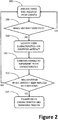
Figure 2 shows, in a flow diagram, an example process implemented according the present disclosure for identifying and reducing the effects of electromagnetic noise in images displayed by a TV. - In one known approach to detecting the effect of electromagnetic noise received by a television (TV) on a broadcast image being displayed by the television, monitoring electronics are installed within the television to analyse image signals being generated to control the display and to compare those generated image signals with a reference signal. However, such techniques are known to have a high error margin, one reason being that the electromagnetic noise that is causing the problem in the generated image may also affect the monitoring equipment being used to determine the extent of the problem, unless the monitoring equipment is very well isolated. Another factor is the use in such monitoring equipment of an estimation method to detect noise, that is, to estimate the noise in the generated image, which is not necessarily an accurate or efficient technique.
- According to an example disclosed herein, a different approach is used to determine the effect upon a generated image of electromagnetic noise and to determine a correction to be made to the filter characteristics of a configurable filter system within the TV to reduce that effect and so improve image quality. This example will now be described initially with reference to
Figure 1 . - Referring to
Figure 1 , an example is shown schematically of an arrangement comprising acamera 100 positioned in front of aTV display 101 such that the whole or a portion of the display area is within the field of view of the camera. Thecamera 100 is linked to acontrol unit 102 by means of acommunication line 103. Thecontrol unit 102 comprises a digital processor for executing a computer program or a combination of a digital processor and a configurable hardware logic unit, a memory unit and interfacing circuits arranged to receive image data from thecamera 100 and to implement functionality to be described below. - The TV 101 includes a configurable
analogue filter system 104 for filtering electromagnetic noise as may be received by anantenna 107 mixed with signals of broadcast TV channels, the received signals being fed to the TV via acable 108. Thefilter system 104 may include variable capacitors, in particular one or more digitally tunable variable capacitors, so that the filtering characteristics of thefilter system 104 may be varied. Thefilter system 104 may also include a digital filter having one or more configurable parameters to enable the characteristics of the digital filter to be adjusted. After filtering, the signals are decoded by conventional means and the resultant images and sound are supplied (106) to theTV display 101, including any image artefacts resulting from the presence of any electromagnetic noise that has not been suppressed by thefilter system 104. - The
control unit 102 is linked to thefilter system 104 of the TV 101 via acommunication line 105 which may be detached from the TV when testing and reconfiguration is complete. Thecontrol unit 102 is arranged to communicate with thefilter system 104 over thecommunication line 105, for example using a known serial peripheral interface (SPI) or an I2C interface between thecontrol unit 102 and thefilter system 104 via theline 105, to trigger changes to the filtering characteristics of thefilter system 104. The changes may be determined by functionality implemented in thecontrol unit 102 based upon analysis by thecontrol unit 102 of the captured images in a process that will now be described additionally with reference toFigure 2 . - Referring additionally to
Figure 2 , thecontrol unit 102 is arranged firstly, at 200, to process image data received from thecamera 100 of at least a portion of theTV display 101 to identify one or more undesirable artefacts in the images being displayed. Thecontrol unit 102 is arranged to recognise any one of a predetermined set of undesirable image artefacts. For example, thecontrol unit 102 may be arranged to identify undesirable image artefacts such as mosaics, distortion or oscillation in a displayed image. There are a number of known image data processing techniques that may be used to identify the presence of particular artefacts in one or more images represented by those image data. Each image artefact has one or more distinctive characteristics that may be recognised either by analysis of a single image or by analysis of a sequence of images, if necessary by comparison with reference data. Image data received at 200 may comprise image data of a sequence of images, each captured by thecamera 100 over a time period of at least the normally expected minimum period of response of the human eye. This ensures that the images represented in the image data are as they would be perceived by a human user. For aTV display 101 with an image refresh rate of 50Hz, for example, in which the image is refreshed every 20ms, image data for each image may be captured by thecamera 100 over a time period of greater that 20ms so that the intended colour and brightness of each pixel is accurately captured by thecamera 100. Typically, a sequence of for example ten images may be captured by thecamera 100 and analysed at 200 to detect any of the different types of image artefact resulting from electromagnetic noise. - Each type of undesirable image artefact is known to be associated with a particular known type of electromagnetic noise. That is, it is known, or it may be determined by routine experimentation, what type of electromagnetic noise must be present in a received signal at the
antenna 107 to result in the particular image artefact being displayed by a particular TV product or by a TV using a known digital display type. The expected response of the TV signal decoding techniques implemented in the TV and of other image-affecting components in the TV to each type of noise is also known. Furthermore, for each undesirable artefact, it is known how the electromagnetic noise causing the artefact to appear relates to the signals of the TV channel being received and displayed, e.g. in terms of the relative frequencies and harmonics of the noise and the differences in signal composition. - With this knowledge, a predetermined set of responses may be defined in terms of the characteristics of the
filter system 104 required to suppress or reduce each of the types of noise known to result in respective undesirable display artefacts in a particular TV product. Such responses may be stored in a look-up table in a memory unit for access by the functionality of thecontrol unit 102, or they may be implemented in functionality of thecontrol unit 102. As required, a different set of responses may be defined for each of a number of different TV products or digital display types so that thecontrol unit 102 may be used in testing and configuration of more than one TV product. - Functionality implemented by the
control unit 102 is therefore arranged if, at 205, the presence is identified in received image data of a type of one or more undesirable image artefacts, to identify, at 210, the filter characteristics required of thefilter system 104 and, at 215, to generate signals for sending to thefilter system 104 to adjust the filter characteristics accordingly. The aim of such adjustments is to avoid or to reduce the generation of the identified undesirable image artefact. Therefore, having triggered the adjustments to thefilter system 104, thecontrol unit 102 may be arranged, at 220, to check that the identified undesirable image artefact is no longer present or is at least reduced in displayed images by capturing new image data and analysing them again. If, at 220, the identified image artefact has been reduced or eliminated then, at 225, the process may finalise the filter characteristics of thefilter system 104 and terminate the process. Otherwise, the process may return to 200 to receive more data from thecamera 100 and continue the analysis and adjustment. - Where it is not known what particular filter characteristics will result in correction of an undesirable image artefact, the
control unit 102 may be arranged to implement an iterative process of adjustment to the filter system 10 and analysis of images to determine whether an adjustment has resulted in an improvement or a degradation of the displayed images. Thecontrol unit 102 may implement a predetermined strategy for iterative adjustment of thefilter system 104 to result in an improved image quality for a given electromagnetic noise component in received signals. The iterative process may include receiving different channels and making different adjustments to thefilter system 104 for each received channel to obtain an optimal balance of improved image quality across two or more different channels. In this way, adjustments that improve picture for one channel but degrade the image quality for other channels may be avoided or a compromise adjustment may be found to give an overall acceptable result. - When the filter characteristics have been determined, then at 225, a command may be generated by the
control unit 102 for sending to thefilter system 104 to indicate that the determined filter characteristics are the final characteristics and that the adjustment process is complete. - A significant advantage in determining resultant undesirable image artefacts using a
camera 100 andcontrol unit 102 separate from the functionality of theTV 101 is that thecamera 100 andcontrol unit 102 are isolated from the electromagnetic noise signals being received by or otherwise penetrating theTV 101. Furthermore, as indicated above, thecamera 100 andcontrol unit 102 may be used to configure multiple different TVs of the same type and of different types to improve their electromagnetic noise tolerance and resultant image quality. - It was indicated above that the
camera 100 may be positioned to capture a whole of the image being displayed by theTV display 101 or to capture only a portion of the displayed image. It may be beneficial to position thecamera 100 to capture only a portion of the displayed image with a higher resolution than may be possible when imaging the whole of the TV display area. This may enable undesirable image artefacts to be identified by thecontrol unit 102 with greater reliability. In particular, where the undesirable artefact is expected to affect an image over the whole of the display area, the artefact may be identified in high quality image data captured from only a portion of the display. - Whereas the functionality of the
controller 102 has been described in the context of a controller that is separate from the TV, certain functionality of thecontroller 102 may be implemented within a TV itself so that only thecamera 100 needs to be linked to the TV for the purpose of testing and adjustment. - In yet another arrangement, a camera may be built into the TV to view a small portion of the image area of the
display 101 and to capture sufficient image data to be able to identify undesirable image artefacts. This is increasingly feasible with very high definition TV displays, allowing for the sampling of a much smaller portion of adisplay 101. - It will be understood that the processor or processing system or circuitry referred to herein may in practice be provided by a single chip or integrated circuit or plural chips or integrated circuits, optionally provided as a chipset, an application-specific integrated circuit (ASIC), field-programmable gate array (FPGA), digital signal processor (DSP), graphics processing units (GPUs), etc. The chip or chips may comprise circuitry (as well as possibly firmware) for embodying at least one or more of a data processor or processors, a digital signal processor or processors, baseband circuitry and radio frequency circuitry, which are configurable so as to operate in accordance with the exemplary embodiments. In this regard, the exemplary embodiments may be implemented at least in part by computer software stored in (non-transitory) memory and executable by the processor, or by hardware, or by a combination of tangibly stored software and hardware (and tangibly stored firmware).
- Reference is made herein to memory unit for storing data. This may be provided by a single device or by plural devices. Suitable devices include for example a hard disk and non-volatile semiconductor memory.
- Although at least some aspects of the embodiments described herein with reference to the drawings comprise computer processes performed in processing systems or processors, the invention also extends to computer programs, particularly computer programs on or in a carrier, adapted for putting the invention into practice. The program may be in the form of non-transitory source code, object code, a code intermediate source and object code such as in partially compiled form, or in any other non-transitory form suitable for use in the implementation of processes according to the invention. The carrier may be any entity or device capable of carrying the program. For example, the carrier may comprise a storage medium, such as a solid-state drive (SSD) or other semiconductor-based RAM; a ROM, for example a CD ROM or a semiconductor ROM; a magnetic recording medium, for example a floppy disk or hard disk; optical memory devices in general; etc.
- The examples described herein are to be understood as illustrative examples of embodiments of the invention. Further embodiments and examples are envisaged. Any feature described in relation to any one example or embodiment may be used alone or in combination with other features. In addition, any feature described in relation to any one example or embodiment may also be used in combination with one or more features of any other of the examples or embodiments, or any combination of any other of the examples or embodiments. Furthermore, equivalents and modifications not described herein may also be employed within the scope of the invention, which is defined in the claims.
Claims (15)
- A method for reducing the effect of electromagnetic noise on images displayed by a television, the television having a display (101), an input (107, 108) for receiving television signals, and a configurable filter (104) for filtering received television signals, the method comprising:(i) receiving, from a camera (100) directed towards the display (101), image data representing at least a portion of an image being displayed by the television;(ii) analysing the received image data to identify a presence, in the at least a portion of an image being displayed, of one or more of a predetermined set of image artefacts known to result from the presence of electromagnetic noise;(iii) determining filter characteristics for the configurable filter corresponding to an image artefact identified at (ii); and(iv) generating signals for sending to the configurable filter (104) to implement the filter characteristics determined at (iii), thereby to reduce the presence of the identified image artefact.
- The method according to claim 1, wherein (ii) comprises analysing image data received at (i) in respect of two or more displayed images to identify a presence of an image artefact of the predetermined set of image artefacts.
- The method according to claim 1 or claim 2, wherein at (ii) the set of predetermined image artefacts includes at least one of: mosaic or tiling effects; image distortion; and image oscillation.
- The method according to any one of claims 1 to 3, comprising:
(v) receiving image data after generating the signals for sending to the configurable filter (104) at (iv) to determine whether the determined adjustment to the configurable filter (104) has at least reduced the presence of the identified image artefact as compared with the presence identified at (ii). - The method according to claim 4, comprising repeating (ii) to (v) in an iterative process to determine filter characteristics resulting in at least a predetermined reduction in the presence of the image artefact identified at (ii).
- The method according to any one of claims 1 to 5, wherein (iii) comprises accessing a data store storing configurable filter characteristics corresponding to each image artefact of the predetermined set of image artefacts.
- The method according to claim 6, wherein the data store stores configurable filter characteristics for a plurality of different television products and (iii) comprises selecting from the configurable filter characteristics stored in the data store for a respective television.
- An apparatus for reducing the effect of electromagnetic noise in images displayed by a television on a display (101), the television having a configurable filter (104) for use in filtering electromagnetic noise from signals to be used in displaying images on the display (101), the apparatus comprising:a camera (100) for generating image data representing an image being displayed by at least a portion of the display (101); anda controller (102) configured:(i) to receive image data from the camera (100);(ii) to analyse the received image data to identify a presence, in the at least a portion of an image represented in the received image data, of one or more of a predetermined set of display artefacts known to result from the presence of electromagnetic noise;(iii) to determine filter characteristics for the configurable filter (104) corresponding to a display artefact identified at (ii); and(iv) to generate signals for output to the configurable filter (104) to implement the determined filter characteristics.
- The apparatus according to claim 8, wherein the controller (102) is configured, at (ii), to analyse image data received at (i) in respect of two or more displayed images to identify a presence of an image artefact of the predetermined set of image artefacts.
- The apparatus according to claim 8 or claim 9, wherein at (ii) the set of predetermined image artefacts includes at least one of: mosaic or tiling effects; image distortion; and image oscillation.
- The apparatus according to any one of claims 8 to 10, wherein the controller (102) is configured:
(v) to receive image data after generating the signals for sending to the configurable filter (104) at (iv) to determine whether the determined adjustment to the configurable filter (104) has at least reduced the presence of the identified image artefact as compared with the presence identified at (ii). - The apparatus according to claim 11, wherein the controller (102) is configured to repeat (ii) to (v) in an iterative process to determine filter characteristics resulting in at least a predetermined reduction in the presence of the image artefact identified at (ii).
- The apparatus according to any one of claims 8 to 12, the controller (102) is configured, a (iii), to access a data store storing configurable filter characteristics corresponding to each image artefact of the predetermined set of image artefacts.
- The apparatus according to claim 13, wherein the data store stores configurable filter characteristics for a plurality of different television products and the controller (102) is configured, at (iii), to select from the configurable filter characteristics stored in the data store for a respective television.
- A computer program which when installed upon and executed by a digital processor implements the method according to any one of claims 1 to 7.
Priority Applications (1)
| Application Number | Priority Date | Filing Date | Title |
|---|---|---|---|
| EP17194156.0A EP3462736B1 (en) | 2017-09-29 | 2017-09-29 | Method, apparatus and computer program for reducing the effect in displayed tv images of electromagnetic noise |
Applications Claiming Priority (1)
| Application Number | Priority Date | Filing Date | Title |
|---|---|---|---|
| EP17194156.0A EP3462736B1 (en) | 2017-09-29 | 2017-09-29 | Method, apparatus and computer program for reducing the effect in displayed tv images of electromagnetic noise |
Publications (2)
| Publication Number | Publication Date |
|---|---|
| EP3462736A1 true EP3462736A1 (en) | 2019-04-03 |
| EP3462736B1 EP3462736B1 (en) | 2020-11-04 |
Family
ID=60019713
Family Applications (1)
| Application Number | Title | Priority Date | Filing Date |
|---|---|---|---|
| EP17194156.0A Active EP3462736B1 (en) | 2017-09-29 | 2017-09-29 | Method, apparatus and computer program for reducing the effect in displayed tv images of electromagnetic noise |
Country Status (1)
| Country | Link |
|---|---|
| EP (1) | EP3462736B1 (en) |
Citations (2)
| Publication number | Priority date | Publication date | Assignee | Title |
|---|---|---|---|---|
| EP1789945A1 (en) * | 2004-08-30 | 2007-05-30 | Optofidelity OY | A method for testing electronic devices |
| US20120127324A1 (en) * | 2010-11-23 | 2012-05-24 | Dolby Laboratories Licensing Corporation | Method and System for Display Characterization or Calibration Using A Camera Device |
-
2017
- 2017-09-29 EP EP17194156.0A patent/EP3462736B1/en active Active
Patent Citations (2)
| Publication number | Priority date | Publication date | Assignee | Title |
|---|---|---|---|---|
| EP1789945A1 (en) * | 2004-08-30 | 2007-05-30 | Optofidelity OY | A method for testing electronic devices |
| US20120127324A1 (en) * | 2010-11-23 | 2012-05-24 | Dolby Laboratories Licensing Corporation | Method and System for Display Characterization or Calibration Using A Camera Device |
Also Published As
| Publication number | Publication date |
|---|---|
| EP3462736B1 (en) | 2020-11-04 |
Similar Documents
| Publication | Publication Date | Title |
|---|---|---|
| US6717622B2 (en) | System and method for scalable resolution enhancement of a video image | |
| CN107731148B (en) | A display screen voltage configuration method, device and display device | |
| US9875522B2 (en) | Display control apparatus | |
| EP3731221B1 (en) | Image brightness adjustment method, device and system, and computer-readable storage medium | |
| RU2654501C2 (en) | Chroma subsampling | |
| US8743212B2 (en) | Optimizing content calibration for home theaters | |
| US11361408B2 (en) | Image processing apparatus, system, image processing method, and non-transitory computer-readable storage medium | |
| CN110719417A (en) | High definition analog video and control link for automotive applications | |
| JP7523625B2 (en) | Image processing device, image processing method, and control program | |
| US20110063455A1 (en) | Monitoring Quality Of Video Signals | |
| EP3462736B1 (en) | Method, apparatus and computer program for reducing the effect in displayed tv images of electromagnetic noise | |
| TW201515438A (en) | Testing system and method thereof | |
| US20190370596A1 (en) | Information-processing apparatus and information-processing method | |
| CN110891147A (en) | Video recording device and video computing method | |
| US20100157161A1 (en) | Gamma Correction Apparatus and Method | |
| EP2982106B1 (en) | Guided 3d display adaptation | |
| US11929043B1 (en) | Detection circuit, detection method and image processing system for local dimming control | |
| US20170060797A1 (en) | Information Processing Method And Electronic Device | |
| CN112333440B (en) | TV board card detection method and device, terminal equipment and storage medium | |
| US9854233B2 (en) | Apparatus for processing video, method of driving apparatus for processing video, and computer readable recording medium | |
| KR101739822B1 (en) | Method and apparatus for compressing analog image signal | |
| EP1615423A1 (en) | A method and a system for calibrating an analogue video interface | |
| US8774549B2 (en) | Compression error handling for temporal noise reduction | |
| US20100277647A1 (en) | Noise detection method and image processing method using the noise detection method | |
| KR20090034107A (en) | Image quality measuring device and its method |
Legal Events
| Date | Code | Title | Description |
|---|---|---|---|
| PUAI | Public reference made under article 153(3) epc to a published international application that has entered the european phase |
Free format text: ORIGINAL CODE: 0009012 |
|
| STAA | Information on the status of an ep patent application or granted ep patent |
Free format text: STATUS: THE APPLICATION HAS BEEN PUBLISHED |
|
| AK | Designated contracting states |
Kind code of ref document: A1 Designated state(s): AL AT BE BG CH CY CZ DE DK EE ES FI FR GB GR HR HU IE IS IT LI LT LU LV MC MK MT NL NO PL PT RO RS SE SI SK SM TR |
|
| AX | Request for extension of the european patent |
Extension state: BA ME |
|
| STAA | Information on the status of an ep patent application or granted ep patent |
Free format text: STATUS: REQUEST FOR EXAMINATION WAS MADE |
|
| 17P | Request for examination filed |
Effective date: 20191004 |
|
| RBV | Designated contracting states (corrected) |
Designated state(s): AL AT BE BG CH CY CZ DE DK EE ES FI FR GB GR HR HU IE IS IT LI LT LU LV MC MK MT NL NO PL PT RO RS SE SI SK SM TR |
|
| REG | Reference to a national code |
Ref country code: DE Ref legal event code: R079 Ref document number: 602017026725 Country of ref document: DE Free format text: PREVIOUS MAIN CLASS: H04N0017040000 Ipc: H04N0017000000 |
|
| GRAP | Despatch of communication of intention to grant a patent |
Free format text: ORIGINAL CODE: EPIDOSNIGR1 |
|
| STAA | Information on the status of an ep patent application or granted ep patent |
Free format text: STATUS: GRANT OF PATENT IS INTENDED |
|
| RIC1 | Information provided on ipc code assigned before grant |
Ipc: H04N 17/00 20060101AFI20200430BHEP Ipc: H04N 5/213 20060101ALI20200430BHEP Ipc: H04N 17/04 20060101ALI20200430BHEP |
|
| INTG | Intention to grant announced |
Effective date: 20200526 |
|
| GRAS | Grant fee paid |
Free format text: ORIGINAL CODE: EPIDOSNIGR3 |
|
| GRAA | (expected) grant |
Free format text: ORIGINAL CODE: 0009210 |
|
| STAA | Information on the status of an ep patent application or granted ep patent |
Free format text: STATUS: THE PATENT HAS BEEN GRANTED |
|
| AK | Designated contracting states |
Kind code of ref document: B1 Designated state(s): AL AT BE BG CH CY CZ DE DK EE ES FI FR GB GR HR HU IE IS IT LI LT LU LV MC MK MT NL NO PL PT RO RS SE SI SK SM TR |
|
| REG | Reference to a national code |
Ref country code: GB Ref legal event code: FG4D |
|
| REG | Reference to a national code |
Ref country code: CH Ref legal event code: EP |
|
| REG | Reference to a national code |
Ref country code: AT Ref legal event code: REF Ref document number: 1332339 Country of ref document: AT Kind code of ref document: T Effective date: 20201115 |
|
| REG | Reference to a national code |
Ref country code: DE Ref legal event code: R096 Ref document number: 602017026725 Country of ref document: DE |
|
| REG | Reference to a national code |
Ref country code: IE Ref legal event code: FG4D |
|
| REG | Reference to a national code |
Ref country code: NL Ref legal event code: MP Effective date: 20201104 |
|
| REG | Reference to a national code |
Ref country code: AT Ref legal event code: MK05 Ref document number: 1332339 Country of ref document: AT Kind code of ref document: T Effective date: 20201104 |
|
| PG25 | Lapsed in a contracting state [announced via postgrant information from national office to epo] |
Ref country code: FI Free format text: LAPSE BECAUSE OF FAILURE TO SUBMIT A TRANSLATION OF THE DESCRIPTION OR TO PAY THE FEE WITHIN THE PRESCRIBED TIME-LIMIT Effective date: 20201104 Ref country code: GR Free format text: LAPSE BECAUSE OF FAILURE TO SUBMIT A TRANSLATION OF THE DESCRIPTION OR TO PAY THE FEE WITHIN THE PRESCRIBED TIME-LIMIT Effective date: 20210205 Ref country code: NO Free format text: LAPSE BECAUSE OF FAILURE TO SUBMIT A TRANSLATION OF THE DESCRIPTION OR TO PAY THE FEE WITHIN THE PRESCRIBED TIME-LIMIT Effective date: 20210204 Ref country code: RS Free format text: LAPSE BECAUSE OF FAILURE TO SUBMIT A TRANSLATION OF THE DESCRIPTION OR TO PAY THE FEE WITHIN THE PRESCRIBED TIME-LIMIT Effective date: 20201104 Ref country code: PT Free format text: LAPSE BECAUSE OF FAILURE TO SUBMIT A TRANSLATION OF THE DESCRIPTION OR TO PAY THE FEE WITHIN THE PRESCRIBED TIME-LIMIT Effective date: 20210304 |
|
| PG25 | Lapsed in a contracting state [announced via postgrant information from national office to epo] |
Ref country code: SE Free format text: LAPSE BECAUSE OF FAILURE TO SUBMIT A TRANSLATION OF THE DESCRIPTION OR TO PAY THE FEE WITHIN THE PRESCRIBED TIME-LIMIT Effective date: 20201104 Ref country code: BG Free format text: LAPSE BECAUSE OF FAILURE TO SUBMIT A TRANSLATION OF THE DESCRIPTION OR TO PAY THE FEE WITHIN THE PRESCRIBED TIME-LIMIT Effective date: 20210204 Ref country code: LV Free format text: LAPSE BECAUSE OF FAILURE TO SUBMIT A TRANSLATION OF THE DESCRIPTION OR TO PAY THE FEE WITHIN THE PRESCRIBED TIME-LIMIT Effective date: 20201104 Ref country code: IS Free format text: LAPSE BECAUSE OF FAILURE TO SUBMIT A TRANSLATION OF THE DESCRIPTION OR TO PAY THE FEE WITHIN THE PRESCRIBED TIME-LIMIT Effective date: 20210304 Ref country code: PL Free format text: LAPSE BECAUSE OF FAILURE TO SUBMIT A TRANSLATION OF THE DESCRIPTION OR TO PAY THE FEE WITHIN THE PRESCRIBED TIME-LIMIT Effective date: 20201104 Ref country code: AT Free format text: LAPSE BECAUSE OF FAILURE TO SUBMIT A TRANSLATION OF THE DESCRIPTION OR TO PAY THE FEE WITHIN THE PRESCRIBED TIME-LIMIT Effective date: 20201104 Ref country code: ES Free format text: LAPSE BECAUSE OF FAILURE TO SUBMIT A TRANSLATION OF THE DESCRIPTION OR TO PAY THE FEE WITHIN THE PRESCRIBED TIME-LIMIT Effective date: 20201104 |
|
| REG | Reference to a national code |
Ref country code: LT Ref legal event code: MG9D |
|
| PG25 | Lapsed in a contracting state [announced via postgrant information from national office to epo] |
Ref country code: HR Free format text: LAPSE BECAUSE OF FAILURE TO SUBMIT A TRANSLATION OF THE DESCRIPTION OR TO PAY THE FEE WITHIN THE PRESCRIBED TIME-LIMIT Effective date: 20201104 |
|
| PG25 | Lapsed in a contracting state [announced via postgrant information from national office to epo] |
Ref country code: RO Free format text: LAPSE BECAUSE OF FAILURE TO SUBMIT A TRANSLATION OF THE DESCRIPTION OR TO PAY THE FEE WITHIN THE PRESCRIBED TIME-LIMIT Effective date: 20201104 Ref country code: SK Free format text: LAPSE BECAUSE OF FAILURE TO SUBMIT A TRANSLATION OF THE DESCRIPTION OR TO PAY THE FEE WITHIN THE PRESCRIBED TIME-LIMIT Effective date: 20201104 Ref country code: SM Free format text: LAPSE BECAUSE OF FAILURE TO SUBMIT A TRANSLATION OF THE DESCRIPTION OR TO PAY THE FEE WITHIN THE PRESCRIBED TIME-LIMIT Effective date: 20201104 Ref country code: CZ Free format text: LAPSE BECAUSE OF FAILURE TO SUBMIT A TRANSLATION OF THE DESCRIPTION OR TO PAY THE FEE WITHIN THE PRESCRIBED TIME-LIMIT Effective date: 20201104 Ref country code: EE Free format text: LAPSE BECAUSE OF FAILURE TO SUBMIT A TRANSLATION OF THE DESCRIPTION OR TO PAY THE FEE WITHIN THE PRESCRIBED TIME-LIMIT Effective date: 20201104 Ref country code: LT Free format text: LAPSE BECAUSE OF FAILURE TO SUBMIT A TRANSLATION OF THE DESCRIPTION OR TO PAY THE FEE WITHIN THE PRESCRIBED TIME-LIMIT Effective date: 20201104 |
|
| REG | Reference to a national code |
Ref country code: DE Ref legal event code: R097 Ref document number: 602017026725 Country of ref document: DE |
|
| PG25 | Lapsed in a contracting state [announced via postgrant information from national office to epo] |
Ref country code: DK Free format text: LAPSE BECAUSE OF FAILURE TO SUBMIT A TRANSLATION OF THE DESCRIPTION OR TO PAY THE FEE WITHIN THE PRESCRIBED TIME-LIMIT Effective date: 20201104 |
|
| PLBE | No opposition filed within time limit |
Free format text: ORIGINAL CODE: 0009261 |
|
| STAA | Information on the status of an ep patent application or granted ep patent |
Free format text: STATUS: NO OPPOSITION FILED WITHIN TIME LIMIT |
|
| 26N | No opposition filed |
Effective date: 20210805 |
|
| PG25 | Lapsed in a contracting state [announced via postgrant information from national office to epo] |
Ref country code: IT Free format text: LAPSE BECAUSE OF FAILURE TO SUBMIT A TRANSLATION OF THE DESCRIPTION OR TO PAY THE FEE WITHIN THE PRESCRIBED TIME-LIMIT Effective date: 20201104 Ref country code: NL Free format text: LAPSE BECAUSE OF FAILURE TO SUBMIT A TRANSLATION OF THE DESCRIPTION OR TO PAY THE FEE WITHIN THE PRESCRIBED TIME-LIMIT Effective date: 20201104 Ref country code: AL Free format text: LAPSE BECAUSE OF FAILURE TO SUBMIT A TRANSLATION OF THE DESCRIPTION OR TO PAY THE FEE WITHIN THE PRESCRIBED TIME-LIMIT Effective date: 20201104 |
|
| PG25 | Lapsed in a contracting state [announced via postgrant information from national office to epo] |
Ref country code: SI Free format text: LAPSE BECAUSE OF FAILURE TO SUBMIT A TRANSLATION OF THE DESCRIPTION OR TO PAY THE FEE WITHIN THE PRESCRIBED TIME-LIMIT Effective date: 20201104 |
|
| REG | Reference to a national code |
Ref country code: CH Ref legal event code: PL |
|
| REG | Reference to a national code |
Ref country code: BE Ref legal event code: MM Effective date: 20210930 |
|
| PG25 | Lapsed in a contracting state [announced via postgrant information from national office to epo] |
Ref country code: IS Free format text: LAPSE BECAUSE OF FAILURE TO SUBMIT A TRANSLATION OF THE DESCRIPTION OR TO PAY THE FEE WITHIN THE PRESCRIBED TIME-LIMIT Effective date: 20210304 Ref country code: MC Free format text: LAPSE BECAUSE OF FAILURE TO SUBMIT A TRANSLATION OF THE DESCRIPTION OR TO PAY THE FEE WITHIN THE PRESCRIBED TIME-LIMIT Effective date: 20201104 |
|
| PG25 | Lapsed in a contracting state [announced via postgrant information from national office to epo] |
Ref country code: LU Free format text: LAPSE BECAUSE OF NON-PAYMENT OF DUE FEES Effective date: 20210929 Ref country code: IE Free format text: LAPSE BECAUSE OF NON-PAYMENT OF DUE FEES Effective date: 20210929 Ref country code: FR Free format text: LAPSE BECAUSE OF NON-PAYMENT OF DUE FEES Effective date: 20210930 Ref country code: BE Free format text: LAPSE BECAUSE OF NON-PAYMENT OF DUE FEES Effective date: 20210930 |
|
| PG25 | Lapsed in a contracting state [announced via postgrant information from national office to epo] |
Ref country code: LI Free format text: LAPSE BECAUSE OF NON-PAYMENT OF DUE FEES Effective date: 20210930 Ref country code: CH Free format text: LAPSE BECAUSE OF NON-PAYMENT OF DUE FEES Effective date: 20210930 |
|
| PG25 | Lapsed in a contracting state [announced via postgrant information from national office to epo] |
Ref country code: CY Free format text: LAPSE BECAUSE OF FAILURE TO SUBMIT A TRANSLATION OF THE DESCRIPTION OR TO PAY THE FEE WITHIN THE PRESCRIBED TIME-LIMIT Effective date: 20201104 |
|
| PG25 | Lapsed in a contracting state [announced via postgrant information from national office to epo] |
Ref country code: HU Free format text: LAPSE BECAUSE OF FAILURE TO SUBMIT A TRANSLATION OF THE DESCRIPTION OR TO PAY THE FEE WITHIN THE PRESCRIBED TIME-LIMIT; INVALID AB INITIO Effective date: 20170929 |
|
| PGFP | Annual fee paid to national office [announced via postgrant information from national office to epo] |
Ref country code: GB Payment date: 20230920 Year of fee payment: 7 |
|
| PGFP | Annual fee paid to national office [announced via postgrant information from national office to epo] |
Ref country code: DE Payment date: 20230920 Year of fee payment: 7 |
|
| PG25 | Lapsed in a contracting state [announced via postgrant information from national office to epo] |
Ref country code: MK Free format text: LAPSE BECAUSE OF FAILURE TO SUBMIT A TRANSLATION OF THE DESCRIPTION OR TO PAY THE FEE WITHIN THE PRESCRIBED TIME-LIMIT Effective date: 20201104 |
|
| PG25 | Lapsed in a contracting state [announced via postgrant information from national office to epo] |
Ref country code: MT Free format text: LAPSE BECAUSE OF FAILURE TO SUBMIT A TRANSLATION OF THE DESCRIPTION OR TO PAY THE FEE WITHIN THE PRESCRIBED TIME-LIMIT Effective date: 20201104 |
|
| REG | Reference to a national code |
Ref country code: DE Ref legal event code: R119 Ref document number: 602017026725 Country of ref document: DE |
|
| GBPC | Gb: european patent ceased through non-payment of renewal fee |
Effective date: 20240929 |
|
| PG25 | Lapsed in a contracting state [announced via postgrant information from national office to epo] |
Ref country code: DE Free format text: LAPSE BECAUSE OF NON-PAYMENT OF DUE FEES Effective date: 20250401 |
|
| PG25 | Lapsed in a contracting state [announced via postgrant information from national office to epo] |
Ref country code: GB Free format text: LAPSE BECAUSE OF NON-PAYMENT OF DUE FEES Effective date: 20240929 |
|
| PGFP | Annual fee paid to national office [announced via postgrant information from national office to epo] |
Ref country code: TR Payment date: 20250929 Year of fee payment: 9 |