EP3462632A1 - Changing steering matrix corresponding to mu-mimo group to allow access points transmit on wireless communication channel simultaneously - Google Patents
Changing steering matrix corresponding to mu-mimo group to allow access points transmit on wireless communication channel simultaneously Download PDFInfo
- Publication number
- EP3462632A1 EP3462632A1 EP17199039.3A EP17199039A EP3462632A1 EP 3462632 A1 EP3462632 A1 EP 3462632A1 EP 17199039 A EP17199039 A EP 17199039A EP 3462632 A1 EP3462632 A1 EP 3462632A1
- Authority
- EP
- European Patent Office
- Prior art keywords
- access point
- client devices
- frame
- mimo group
- beamforming feedback
- Prior art date
- Legal status (The legal status is an assumption and is not a legal conclusion. Google has not performed a legal analysis and makes no representation as to the accuracy of the status listed.)
- Granted
Links
Images

Classifications
-
- H—ELECTRICITY
- H04—ELECTRIC COMMUNICATION TECHNIQUE
- H04B—TRANSMISSION
- H04B7/00—Radio transmission systems, i.e. using radiation field
- H04B7/02—Diversity systems; Multi-antenna system, i.e. transmission or reception using multiple antennas
- H04B7/04—Diversity systems; Multi-antenna system, i.e. transmission or reception using multiple antennas using two or more spaced independent antennas
- H04B7/06—Diversity systems; Multi-antenna system, i.e. transmission or reception using multiple antennas using two or more spaced independent antennas at the transmitting station
- H04B7/0613—Diversity systems; Multi-antenna system, i.e. transmission or reception using multiple antennas using two or more spaced independent antennas at the transmitting station using simultaneous transmission
- H04B7/0615—Diversity systems; Multi-antenna system, i.e. transmission or reception using multiple antennas using two or more spaced independent antennas at the transmitting station using simultaneous transmission of weighted versions of same signal
- H04B7/0617—Diversity systems; Multi-antenna system, i.e. transmission or reception using multiple antennas using two or more spaced independent antennas at the transmitting station using simultaneous transmission of weighted versions of same signal for beam forming
-
- H—ELECTRICITY
- H04—ELECTRIC COMMUNICATION TECHNIQUE
- H04B—TRANSMISSION
- H04B7/00—Radio transmission systems, i.e. using radiation field
- H04B7/02—Diversity systems; Multi-antenna system, i.e. transmission or reception using multiple antennas
- H04B7/04—Diversity systems; Multi-antenna system, i.e. transmission or reception using multiple antennas using two or more spaced independent antennas
- H04B7/0413—MIMO systems
- H04B7/0452—Multi-user MIMO systems
-
- H—ELECTRICITY
- H04—ELECTRIC COMMUNICATION TECHNIQUE
- H04B—TRANSMISSION
- H04B7/00—Radio transmission systems, i.e. using radiation field
- H04B7/02—Diversity systems; Multi-antenna system, i.e. transmission or reception using multiple antennas
- H04B7/04—Diversity systems; Multi-antenna system, i.e. transmission or reception using multiple antennas using two or more spaced independent antennas
- H04B7/0413—MIMO systems
- H04B7/0456—Selection of precoding matrices or codebooks, e.g. using matrices antenna weighting
-
- H—ELECTRICITY
- H04—ELECTRIC COMMUNICATION TECHNIQUE
- H04B—TRANSMISSION
- H04B7/00—Radio transmission systems, i.e. using radiation field
- H04B7/02—Diversity systems; Multi-antenna system, i.e. transmission or reception using multiple antennas
- H04B7/04—Diversity systems; Multi-antenna system, i.e. transmission or reception using multiple antennas using two or more spaced independent antennas
- H04B7/06—Diversity systems; Multi-antenna system, i.e. transmission or reception using multiple antennas using two or more spaced independent antennas at the transmitting station
- H04B7/0613—Diversity systems; Multi-antenna system, i.e. transmission or reception using multiple antennas using two or more spaced independent antennas at the transmitting station using simultaneous transmission
- H04B7/0615—Diversity systems; Multi-antenna system, i.e. transmission or reception using multiple antennas using two or more spaced independent antennas at the transmitting station using simultaneous transmission of weighted versions of same signal
- H04B7/0619—Diversity systems; Multi-antenna system, i.e. transmission or reception using multiple antennas using two or more spaced independent antennas at the transmitting station using simultaneous transmission of weighted versions of same signal using feedback from receiving side
-
- H—ELECTRICITY
- H04—ELECTRIC COMMUNICATION TECHNIQUE
- H04W—WIRELESS COMMUNICATION NETWORKS
- H04W16/00—Network planning, e.g. coverage or traffic planning tools; Network deployment, e.g. resource partitioning or cells structures
- H04W16/14—Spectrum sharing arrangements between different networks
-
- H—ELECTRICITY
- H04—ELECTRIC COMMUNICATION TECHNIQUE
- H04B—TRANSMISSION
- H04B7/00—Radio transmission systems, i.e. using radiation field
- H04B7/02—Diversity systems; Multi-antenna system, i.e. transmission or reception using multiple antennas
- H04B7/04—Diversity systems; Multi-antenna system, i.e. transmission or reception using multiple antennas using two or more spaced independent antennas
- H04B7/06—Diversity systems; Multi-antenna system, i.e. transmission or reception using multiple antennas using two or more spaced independent antennas at the transmitting station
- H04B7/0613—Diversity systems; Multi-antenna system, i.e. transmission or reception using multiple antennas using two or more spaced independent antennas at the transmitting station using simultaneous transmission
- H04B7/0615—Diversity systems; Multi-antenna system, i.e. transmission or reception using multiple antennas using two or more spaced independent antennas at the transmitting station using simultaneous transmission of weighted versions of same signal
- H04B7/0619—Diversity systems; Multi-antenna system, i.e. transmission or reception using multiple antennas using two or more spaced independent antennas at the transmitting station using simultaneous transmission of weighted versions of same signal using feedback from receiving side
- H04B7/0621—Feedback content
- H04B7/0634—Antenna weights or vector/matrix coefficients
-
- H—ELECTRICITY
- H04—ELECTRIC COMMUNICATION TECHNIQUE
- H04W—WIRELESS COMMUNICATION NETWORKS
- H04W84/00—Network topologies
- H04W84/02—Hierarchically pre-organised networks, e.g. paging networks, cellular networks, WLAN [Wireless Local Area Network] or WLL [Wireless Local Loop]
- H04W84/10—Small scale networks; Flat hierarchical networks
- H04W84/12—WLAN [Wireless Local Area Networks]
-
- H—ELECTRICITY
- H04—ELECTRIC COMMUNICATION TECHNIQUE
- H04W—WIRELESS COMMUNICATION NETWORKS
- H04W88/00—Devices specially adapted for wireless communication networks, e.g. terminals, base stations or access point devices
- H04W88/08—Access point devices
Definitions
- WLAN wireless local area network
- APs adjacent access points in the WLAN may need to share access to the wireless communication channel, which may lead to channel interference to one AP in the WLAN caused by a neighboring AP's transmission.
- access points adjacent to each other can use different non-overlapping frequency bands (or channels) for operation either via manual configuration or through the APs' automatic radio resource management features.
- non-overlapping frequency bands or channels
- nearby APs may need to operate on the same wireless frequency band.
- the medium access protocols can allow sharing the access to the wireless medium, they do not increase channel reuse. Examples of the present disclosure can increase channel reuse by managing interferences from one AP's transmissions to another.
- techniques disclosed in examples herein can allow neighboring APs to transmit at the same time when operating on the same channel that is within the range of each other, thereby increasing the capacity.
- clear channel assessment may refer to a logical function found within physical layers of a wireless communication device (e.g., an access point) which determines the current state of use of a wireless medium.
- the CCA detection threshold can be adjusted to a less sensitive value by a network administrator.
- the less sensitive CCA threshold value may cause the APs to serve a reduced set of client devices, because the AP can no longer receive requests from client devices that are located outside the reduced CCA range.
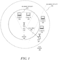
- two access points can transmit simultaneously on the same wireless channel even though AP2 120 is within the CCA range 160 of AP1 110.
- client devices Client1 130 and Client2 135 are associated with AP1 110; and, client devices Client3 140 and Client4 145 are associated with AP2 120.
- the dotted lines may show the range to which the CCA is triggered because of a respective AP.
- CCA range 160 may indicate the range when CCA is triggered for AP1 110.
- the solid line may show the range up to which transmitted frames can be decoded.
- TX range 150 may indicate the transmission range up to which a frame transmitted by an access point or a client device (e.g., Client1 130 or Client2 135) can be decoded by AP1 110.
- AP1 110 detects wireless signals on its wireless operating channel from another AP (e.g., AP2 120) that is located within CCA range 160, without techniques described herein, AP1 110 shall refrain from transmitting on the wireless operating channel for a period of time.
- access point generally refers to receiving points for any known or convenient wireless access technology which may later become known. Specifically, the term AP is not intended to be limited to IEEE 802.11-based APs. APs generally function as an electronic device that is adapted to allow wireless devices to connect to a wired network via various communications standards. As used herein, a “client device” may include a notebook, tablet, mobile phone, and/or other mobile device that can utilize a WLAN connection.
- wireless local area network generally may refer to a communications network links two or more devices using some wireless distribution method (for example, spread-spectrum or orthogonal frequency-division multiplexing radio), and usually providing a connection through an access point to the Internet; and thus, providing users with the mobility to move around within a local coverage area and still stay connected to the network.
- some wireless distribution method for example, spread-spectrum or orthogonal frequency-division multiplexing radio
- AP1 110 can create a MU-MIMO group 170 that includes both Client1 130 and Client2 135.
- AP2 120 can create a MU-MIMO group 180 that includes both Client3 140 and Client4 145.
- the multi-user MIMO technique works by taking advantage of beamforming to send frames to spatially diverse locations at the same time.
- beamforming generally may refer to a way of wireless transmission that allows a transmitter to focus energy toward a receiver. Beamformees can be selected by calculating a steering matrix for an antenna array of the access point.
- the steering matrix generally may refer to a mathematical description of how the antenna array uses each individual element to select a spatial path for the data transmission.
- AP1 110 may also trigger the CCA at AP2 120, which is located within CCA range 160 but outside Tx range 150.
- CCA is triggered at AP2 120, which means that AP2 120 detects a transmission signal from AP1 110 that is stronger than the CCA threshold value, then AP2 120 cannot transmit simultaneously on the same wireless communication channel as AP1 110.
- AP1 110 may treat AP2 120 as one of its client devices. Therefore, the MU-MIMO group 170 formed by AP1 110 can be modified to include Client1 130, Client2 135, and AP2 120. Then, AP1 110 will follow a MU-MIMO sounding protocol to sound the channel between AP110 and each of Client1 130, Client2 135, and AP2 120. In a MU-MIMO transmission towards multiple client devices, one intended client device will receive the data transmission, whereas the other client devices in the same MU-MIMO group will receive a NULL frame.
- AP2 120 when AP2 120 is a member of the MU-MIMO group 170, when AP1 110 transmission data frames to Client2 135, both Client1 130 and AP2 120 will receive NULL frames, e.g., NULL message 180.
- AP1 110 can be informed of the channel condition between AP1 110 and AP2 120.
- AP1 110 and AP2 120 operate on the same channel, sounding frames sent by AP2 120 to its own clients (e.g., Client3 140 and Client4 145) can be heard by AP1 110 as well.
- the beamforming steering matrix V generated at AP1 110 can be used to create a NULL message 180 to transmit in AP2 120's direction, which can reduce the chance that the CCA is triggered at AP2 120.
- AP1 110 can selectively isolate AP2 120 while maintaining connections to the farthest client device of AP1 110.
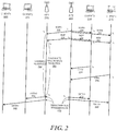
- FIG. 2 is a sequence diagram illustrating example communication sequences for changing a steering matrix corresponding to MU-MIMO group to allow access points transmit on wireless communication channel simultaneously.
- FIG. 2 includes, for example, AP1 220, AP2 225, and a plurality of client devices, such as, Client1 200, Client2 212, Client3 214, and Client4 216.
- Client1 200 and Client2 212 are associated with AP1 220; and, Client3 214 and Client4 216 are associated with AP2 225.
- AP1 220 can form a MU-MIMO group that includes Client1 200, Client2 212, and AP2 225.
- AP2 can form a MU-MIMO group that includes Client3 214, Client4 216, and AP1 220.
- AP2 225 sends a Null Data Packet Announcement (NDPA) 230.
- NDPA 230 is received by Client3 214 and Client4 216 at time point t 2 .
- AP1 220 also receives the NDPA 230 at time point t 3 .
- AP2 225 next transmits a Null Data Packet (NDP) frame 232, which is the frame used to calibrate the channel.
- NDP 232 is subsequently received by Client3 214 and Client4 216 at time point t 5 .
- AP1 220 can receive the NDP 232 at time point t 6 .
- AP2 225 can transmit from each of its antennas one at a time.
- the header of NDP 232 can identify which antenna the frame is sent from.
- a beamformee device can record information about how it receives a sounding frame on each of its antennas individually. This results in an M to N relation over the number of antennas at AP2 225 and the number of antennas at the client device (e.g., Client3 214).
- the client device may record the following data for every MN relation: (1) the strength of the signal measured by its amplitude; and (2) the time it received the signal. The differences in these times can be recorded in a matrix, which is also known as Channel State Information (CSI).
- CSI Channel State Information
- CSI can then be compressed and returned to AP2 225 in a compressed beamforming action feedback frame (CBAF) 234.
- CBAF compressed beamforming action feedback frame
- the targeted beamformees need to reply with CBAF 234.
- the intended client device may reply immediately whereas the other beamformees in the MU-MIMO group may wait to be polled by the beamformer (e.g., AP2 225).
- the beamformer e.g., AP2 225.
- Client3 214 returns CBAF 234 at time point t 7
- Client4 216 returns CBAF 236 to AP2 225 at time point t 8 .
- AP2 225 can then calculate steering matrix that determines how to beamform to Client3 214 and Client4 216 based on CBAF 234 and 236.
- AP1 220 may indicate the channel as reserved 250. Thereafter, when AP1 220 receives NDP 232 at time point t 6 , AP1 220 can calculate a NULL frame in AP2's direction 260 based on information received within NDP 232. The calculation of NULL frame is similar to how a client device calculates the CBAF based on a NDP frame, although no actual frame is transmitted from AP1 220 to AP2 225 in this example. However, AP1 220 can adjust its steering matrix for MU-MIMO group based at least in part on the NULL frame calculation. With the adjusted steering matrix, data transmissions targeted to Client1 200 and Client2 212 can have little interference to AP2 225.
- both AP1 220 and AP2 225 can adjust their respective steering matrix to reduce interference to each other.
- AP1 220 and AP2 225 can start simultaneous transmission 270 on the same wireless communication channel.
- AP1 220 can transmit Data1 240 to Client1 200, Data2 242 to Client2 212; and, AP2 225 can transmit Data3 244 to Client3 214, Data4 246 to Client4 216.
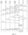
- FIG. 3 is a sequence diagram illustrating example communication sequences for changing a steering matrix corresponding to MU-MIMO group to allow access points transmit on wireless communication channel simultaneously.
- FIG. 3 includes, for example, AP1 320, AP2 330, and AP3 335, as well as a plurality of client devices, such as, Client1 300, Client2 312, Client3 314, and Client4 316.
- Client1 300, Client2 312, Client3 314, and Client4 316 are associated with AP1 320.
- AP2 330 and AP3 335 are within the neighborhood of AP1 320 and operate on the same wireless communication channel as AP1 320 so that the APs can hear the signals transmitted from each other.
- AP1 320 can form a MU-MIMO group that includes Client1 300, Client2 312, Client3 314, and Client4 316 in order to simultaneously transmit data to those client devices.
- AP1 320 sends a Null Data Packet Announcement (NDPA) 340.
- NDPA 340 may be received by Client1 300, Client2 312, Client3 314, and Client4 316 at time point t 2 .
- AP2 330 and AP3 335 can also receive the NDPA 340.
- AP1 320 Upon transmission of NDPA 340, at time point t 3 , AP1 320 next transmits a Null Data Packet (NDP) frame 342, which is the frame used to calibrate the channel state.
- NDP 342 is subsequently received by Client1 300, Client2 312, Client3 314, and Client4 316 at time point t 4 .
- AP1 220 can receive the NDP 232 at time point t 6 .
- Each beamformee need to reply with compressed beamforming action feedback (CBAF) frame 234.
- the intended client device may reply immediately, whereas the other beamformees in the MU-MIMO group may wait to be polled by the beamformer (e.g., AP1 320).
- the beamformer e.g., AP1 320.
- Client4 316 returns CBAF 350 at time point t 5 ;
- Client3 314 returns CBAF 352 at time point t 6 ;
- Client2 312 returns CBAF 354 at time point t 7 ;
- Client1 300 returns CBAF 356 to AP1 320 at time point t 8 .
- AP1 320 can determine how much nulling AP2 330 and AP3 335 may affect data transmissions to Client1 300, Client2 312, Client3 314, and Client4 316, vice versa. To make such determination, AP1 320 first can determine the channel state information (CSI) between a client device (e.g., Client1 300) and itself based on the CBAFs (e.g., CBAFs 350-356) received from each client device in the MU-MIMO group.
- CSI channel state information
- AP1 320 can also determine the channel state between AP1 320 and AP2 330 based on a received compressed beamforming feedback (CBF) frame 360 over the wired connection between AP1 320 and AP2 330.
- CBF compressed beamforming feedback
- AP2 330 receives an NDP frame from AP1 320 and calculates the channel state information based on the signals associated with NDP frame as well as the information stored in the NDP frame.
- the channel state information is returned to AP1 320 in the CBF frame 360 by AP2 330 at time point t 9 .
- AP1 320 can determine the channel state between AP1 320 and AP3 335 based on a CBF 365 transmitted by AP3 335 over the wired connection between AP1 320 and AP3 335 at time point t 10 .
- AP1 320 can create channel state by assuming that the channel is symmetric, and calculating the NULL frame in AP2 330's direction based on a NDP received from AP2 330, and the NULL frame in AP3 335's direction based on a different NDP received from AP3 335.
- AP1 320 can calculate a steering matrix 370 that determines how to beamform to Client1 300, Client2 312, Client3 314, and Client4 316 based on CBAFs 350, 352, 354, and 356. Furthermore, AP1 320 can create a covariance matrix from the client device (e.g., Client1 300) and AP2 330 channel matrices. The rank of this covariance matrix may indicate whether the channel state information of a client device in the MU-MIMO group (e.g., Client1 300) and a neighboring AP (e.g., AP2 330) are linearly independent.
- a high rank may indicate that the channels are independent, which implies that AP1 320 may null out a neighboring AP (e.g., AP2 330) without affecting data transmission to the client device in its MU-MIMO group (e.g., Client1 300).
- a low rank may indicate that the channels are not independent with each other, which implies that AP1 320 may not transfer data simultaneously with a neighboring AP (e.g., AP2 330) without affecting each other.
- AP1 320 Based on the covariance matrix, AP1 320 adjust the MU-MIMO group membership and the steering matrix 370, such that AP1 320 can simultaneously transmit Data1 390 to Client1 300, Data2 392 to Client2 312, Data3 394 to Client3 314, and Data4 396 to Client4 316. Meanwhile, AP2 330 and AP3 335 may be allowed simultaneous data transmission 380 on the same wireless communication channel as well.
- Table 1 below shows an example table that AP1 320 can maintain to indicate channel states between every associated client device in the MU-MIMO group and each neighbor AP operating on the same channel.
- AP1 320 performs such computation, because even if a client device (e.g., Client1 300) and a neighboring AP (e.g., AP2 330) are not in the same location, their channel state might be similar. Thus, data transmissions involving the client device (e.g., Client1 300) may affect data transmissions involving a neighboring AP (e.g., AP2 330), and vice versa. Based on information in Table 1 above, AP1 320 can send data to client devices.
- a client device e.g., Client1 300
- a neighboring AP e.g., AP2 330
- AP1 320 plans to transmit a data packet to Client1 300, Client2 312, and Client3 314; then, AP1 320 can look up in the table and determine to null out AP2 330 but not AP3 335, in case AP1 320 plans to send data packet to Client1 300, Client2 312, and Client3 314 simultaneously. This is because AP2 330 has a high rank in the covariance matrix associated with Client1 300, Client2 312, and Client3 314, whereas AP3 335 has a low rank in the covariance matrix associated with Client3 314.
- AP1 320 can change its steering matrix 370 based on the CBAFs received from Client1 300, Client2 312, and Client3 314 and the CBF received from AP2 330.
- AP1 320 use the resulting steering matrix 370 for beamforming, MU-MIMO data transmission from AP1 320 will be targeted to Client1 300, Client2 312, and Client3 314 and away from AP2 330. Therefore, the CCA threshold is unlikely to be triggered at AP2 330 due to AP1 320's data transmission.
- AP2 330 can simultaneously transmit data packets to its own associated client devices.
- AP3 335 will refrain from any data transmission during the time when AP1 320 is transmitting data to its client devices (e.g., Client1 300, Client2 312, and Client3 314).
- client devices e.g., Client1 300, Client2 312, and Client3 314.
- AP3 335 has a low rank in the covariance matrix associated with Client3 314, possibly because Client3 314 is in the same direction as AP3 335 relative to AP1 320.
- AP1 320 can null out both AP2 330 and AP3 335 based on the information in Table 1. This is because both AP2 330 and AP3 335 have high rank in the covariance matrix associated with Client1 300 and Client2 312. In other words, both AP2 330 and AP3 335 can transmit to its own associated client devices at the same time on the same wireless communication channel as AP1 320.
- the MU-MIMO group may include all four client devices (e.g., Client1 300, Client2 312, Client3 314, and Client4 316), but AP1 320 has data packets to transmit to Client1 300 and Client2 312, not Client3 314 and Client4 316.
- the same computation can also apply to the case where the MU-MIMO group includes two client devices, namely, Client1 300 and Client2 312.
- AP1 320 selects a set of client devices to become members of a MU-MIMO group.
- AP1 320 determines a set of neighboring APs that can become a part of the same MU-MIMO group.
- AP1 320 determines a subset of its client devices that are compatible with the set of neighboring APs in the MU-MIMO group, so that data transmissions to the subset of client devices can be null out at the neighboring APs in the MU-MIMO group.
- AP1 320 when AP1 320 detects that the amount of active traffic associated with its client devices (e.g., Client1 300, Client2 312, Client3 314, and Client4 316) is relatively low, then AP1 320 may give preference to include a greater number of APs in the MU-MIMO group. In this case, because the neighboring AP has a high priority to be included in the MU-MIMO group, if a client device is incompatible with the neighboring AP, then client device will be excluded from the MU-MIMO group.
- client devices e.g., Client1 300, Client2 312, Client3 314, and Client4 316
- AP1 320 may give preference to include its client devices in the MU-MIMO group, and exclude any neighboring AP that is incompatible with the client devices from the MU-MIMO group.
- every AP makes a decision to null out a number of its neighboring APs. This can increase the overall spatial reuse in the network. Moreover, this increase in the network's throughput does not lead to any sacrifice of other resources in the network.
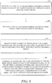
- FIG. 4 is a flowchart of an example process of changing a steering matrix corresponding to MU-MIMO group to allow access points transmit on wireless communication channel simultaneously.
- a first access point can receive a plurality of beamforming feedback frames from a plurality of client devices in a wireless local area network (WLAN) (operation 400). Subsequently, the first access point can overhear a first beamforming feedback frame from a second access point (operation 420). Then, the first access point can calculate a second beamforming feedback frame in response to receiving a sounding frame transmitted from the second access point in the WLAN (operation 440).
- WLAN wireless local area network
- the first access point can select a first subset of the plurality of client devices and the second access point as members of a multi-user multiple input, multiple output (MU-MIMO) group (operation 460). Also, the first access point changing a steering matrix corresponding to the MU-MIMO group based on both the received plurality of beamforming feedback frames and the calculated beamforming feedback frame to allow the first access point and the second access point transmit on a particular wireless communication channel simultaneously without interfering each other (operation 480).
- MU-MIMO multi-user multiple input, multiple output
- FIG. 5 is a flowchart of an example process of changing a steering matrix corresponding to MU-MIMO group to allow access points transmit on wireless communication channel simultaneously.
- the neighboring APs in FIG. 5 provides explicit feedback frame to the access point via a wired and/or wireless connection between the neighboring APs and the access point.
- a network device e.g., an access point
- the network device can receive a particular beamforming feedback frame from a first access point in the WLAN (operation 520).
- the network device can select a first subset of the plurality of client devices and the second access point as members of a multi-user multiple input, multiple output (MU-MIMO) group (operation 540).
- MU-MIMO multi-user multiple input, multiple output
- the network device can change a steering matrix corresponding to the MU-MIMO group based on both the received plurality of beamforming feedback frames and the particular beamforming feedback frame to allow the network device and the first access point transmit on a particular wireless communication channel simultaneously without interfering each other (operation 560).
- the plurality of beamforming feedback frames and the second beamforming feedback frame may include a plurality of compressed beamforming action frames (CBAFs).
- the plurality of CBAFs may be received in response to the first access point transmitting a null data packet (NDP) frame.
- NDP null data packet
- the first access point may transmit a NDP announcement frame (NDPA) prior to transmitting the NDP frame.
- NDPA NDP announcement frame
- selecting the subset of the plurality of client devices and the second access point as members of the MU-MIMO group involves including the second access point in a rank calculation, wherein the second access point is treated as a client device of the first access point for the rank calculation.
- the first access point may include a radio comprising multiple spatial streams, each spatial stream is steered toward a respective member of MU-MIMO group except the second access point according to the rank calculation.
- the first access point can further determine that including the second access point in the MU-MIMO group triggers a clear channel assessment (CCA) threshold, and exclude the second access point from the MU-MIMO group.
- CCA clear channel assessment
- the first access point can further determine that transmitting to a second subset of client devices interferes with wireless transmission of the second access point, wherein network traffic transmitted to the second subset of client devices is low. Then, the first access point can determine that the second access point serves a number of active client devices, and exclude the second subset of client devices from the MU-MIMO group to allow the first access point and the second access point transmit on the particular wireless communication channel simultaneously without interfering each other.
- the first access point can determine that transmitting to a particular client device in the first subset of client devices interferes with wireless transmission of a third access point, whereas the particular client device is inactive. Then, the first access point can include the third access point in the MU-MIMO group to allow the first access point, the second access point, and the third access point transmit on the particular wireless communication channel simultaneously without interfering each other.
- network device generally includes a device that is adapted to transmit and/or receive signaling and to process information within such signaling such as a station (e.g., any data processing equipment such as a computer, cellular phone, personal digital assistant, tablet devices, etc.), an access point, data transfer devices (such as network switches, routers, controllers, etc.) or the like.
- a “network device may refer to a network controller that comprises a hardware or a combination of hardware and software that enables connection between client devices and computer networks.
- a network device may refer to a server computing device (e.g., on-premise server, private, public, or hybrid cloud server) that comprises a hardware or a combination of hardware and software that can process and/or display network-related information.
- a network device may refer to an access point acting as a virtual master network controller among a cluster of access points.
- 'access point' generally refers to receiving points for any known or convenient wireless access technology which may later become known.
- AP is not intended to be limited to IEEE 802.11-based APs.
- APs generally function as an electronic device that is adapted to allow wireless devices to connect to a wired network via various communications standards.
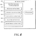
- FIG. 6 is a block diagram of an example network device to change a steering matrix corresponding to MU-MIMO group to allow access points transmit on wireless communication channel simultaneously.
- a network device may be implemented, at least in part, by a combination of hardware and programming.
- the hardware may comprise at least one processor (e.g., processor 610) and the programming may comprise instructions, executable by the processor(s), stored on at least one machine-readable storage medium (e.g., 620).
- a network device may also include embedded memory and a software that can be executed in a host system and serve as a driver of the embedded memory.
- a "processor” may be at least one of a central processing unit (CPU), a semiconductor-based microprocessor, a graphics processing unit (GPU), a field-programmable gate array (FPGA) configured to retrieve and execute instructions, other electronic circuitry suitable for the retrieval and execution instructions stored on a machine-readable storage medium, or a combination thereof.
- CPU central processing unit
- GPU graphics processing unit
- FPGA field-programmable gate array
- the at least one processor 610 may fetch, decode, and execute instructions stored on storage medium 620 to perform the functionalities described below in relation to receiving instructions 630, transmitting instructions 540, calculating instructions 650, selecting instructions 660, and beamforming instructions 670.
- the functionalities of any of the instructions of storage medium 620 may be implemented in the form of electronic circuitry, in the form of executable instructions encoded on a machine-readable storage medium, or a combination thereof.
- the storage medium may be located either in the computing device executing the machine-readable instructions, or remote from but accessible to the computing device (e.g., via a computer network) for execution.
- storage medium 620 may be implemented by one machine-readable storage medium, or multiple machine-readable storage media.
- network device 600 includes at least one processor 610 and machine-readable storage medium 620, it may also include other suitable components, such as additional processing component(s) (e.g., processor(s), ASIC(s), etc.), storage (e.g., storage drive(s), etc.), or a combination thereof.
- additional processing component(s) e.g., processor(s), ASIC(s), etc.
- storage e.g., storage drive(s), etc.
- a "machine-readable storage medium” may be any electronic, magnetic, optical, or other physical storage apparatus to contain or store information such as executable instructions, data, and the like.
- any machine-readable storage medium described herein may be any of Random Access Memory (RAM), volatile memory, non-volatile memory, flash memory, a storage drive (e.g., a hard drive), a solid state drive, any type of storage disc (e.g., a compact disc, a DVD, etc.), and the like, or a combination thereof.
- RAM Random Access Memory
- volatile memory volatile memory
- non-volatile memory flash memory
- a storage drive e.g., a hard drive
- solid state drive any type of storage disc (e.g., a compact disc, a DVD, etc.)
- any machine-readable storage medium described herein may be non-transitory.
- a machine-readable storage medium or media may be part of an article (or article of manufacture). An article or article of manufacture may refer to any manufactured single component or multiple components.
- instructions 630-670 may be executed by processor 610 to: receive a plurality of beamforming feedback frames from a plurality of client devices in a wireless local area network (WLAN); overhear a first beamforming feedback frame from a second access point; calculate a second beamforming feedback frame in response to receiving a sounding frame transmitted from the second access point in the WLAN; select a first subset of the plurality of client devices and the second access point as members of a multi-user multiple input, multiple output (MU-MIMO) group; change a steering matrix corresponding to the MU-MIMO group based on both the received plurality of beamforming feedback frames and the calculated beamforming feedback frame to allow the first access point and the second access point transmit on a particular wireless communication channel simultaneously without interfering each other; receive a particular beamforming feedback frame from a first access point in the WLAN; change a steering matrix corresponding to the MU-MIMO group based on both the received plurality of beamforming feedback frames and the particular beamforming feedback frame to allow the network device and the first access point transmit
- instructions 630-670 may also be executed by processor 610 to: determine that including the second access point in the MU-MIMO group triggers a clear channel assessment (CCA) threshold; exclude the second access point from the MU-MIMO group; determine that transmitting to a second subset of client devices interferes with wireless transmission of the second access point, wherein network traffic transmitted to the second subset of client devices is low; determine that the second access point serves a number of active client devices; exclude the second subset of client devices from the MU-MIMO group to allow the first access point and the second access point transmit on the particular wireless communication channel simultaneously without interfering each other; determine that transmitting to a particular client device in the first subset of client devices interferes with wireless transmission of a third access point, wherein the particular client device is inactive; include the third access point in the MU-MIMO group to allow the first access point, the second access point, and the third access point transmit on the particular wireless communication channel simultaneously without interfering each other; etc.
- CCA clear channel assessment
Landscapes
- Engineering & Computer Science (AREA)
- Computer Networks & Wireless Communication (AREA)
- Signal Processing (AREA)
- Mobile Radio Communication Systems (AREA)
Abstract
Description
- In high density wireless local area network (WLAN) deployments, non-overlapping frequency bands could be scarce. As a result, adjacent access points (APs) in the WLAN may need to share access to the wireless communication channel, which may lead to channel interference to one AP in the WLAN caused by a neighboring AP's transmission.
- The following detailed description references the drawings, wherein:
-
FIG. 1 is a block diagram of an example system environment for changing a steering matrix corresponding to MU-MIMO group to allow access points transmit on wireless communication channel simultaneously; -
FIG. 2 is a sequence diagram illustrating example communication sequences for changing a steering matrix corresponding to MU-MIMO group to allow access points transmit on wireless communication channel simultaneously; -
FIG. 3 is a sequence diagram illustrating example communication sequences for changing a steering matrix corresponding to MU-MIMO group to allow access points transmit on wireless communication channel simultaneously; -
FIG. 4 is a flowchart of an example process of changing a steering matrix corresponding to MU-MIMO group to allow access points transmit on wireless communication channel simultaneously; -
FIG. 5 is a flowchart of an example process of changing a steering matrix corresponding to MU-MIMO group to allow access points transmit on wireless communication channel simultaneously; and -
FIG. 6 is a block diagram of an example network device to change a steering matrix corresponding to MU-MIMO group to allow access points transmit on wireless communication channel simultaneously. - In a typical enterprise WLAN deployment, access points adjacent to each other can use different non-overlapping frequency bands (or channels) for operation either via manual configuration or through the APs' automatic radio resource management features. However, in high density WLAN deployments, especially when the available non-overlapping channels are scarce (e.g., 2.4GHz or via administrator imposed restrictions), nearby APs may need to operate on the same wireless frequency band. While the medium access protocols can allow sharing the access to the wireless medium, they do not increase channel reuse. Examples of the present disclosure can increase channel reuse by managing interferences from one AP's transmissions to another. Specifically, techniques disclosed in examples herein can allow neighboring APs to transmit at the same time when operating on the same channel that is within the range of each other, thereby increasing the capacity.
- According to IEEE 802.11 standards, when two APs are sufficiently located close to each other physically that a clear channel assessment threshold is triggered, the two APs cannot transmit data on the channel together to avoid channel contentions. Generally, clear channel assessment (CCA) may refer to a logical function found within physical layers of a wireless communication device (e.g., an access point) which determines the current state of use of a wireless medium. In some implementations, the CCA detection threshold can be adjusted to a less sensitive value by a network administrator. However, the less sensitive CCA threshold value may cause the APs to serve a reduced set of client devices, because the AP can no longer receive requests from client devices that are located outside the reduced CCA range.
- According to examples of the present disclosure, as illustrated in
FIG. 1 , two access points (e.g.,AP1 110 and AP2 120) can transmit simultaneously on the same wireless channel even thoughAP2 120 is within theCCA range 160 ofAP1 110. InFIG. 1 ,client devices Client1 130 andClient2 135 are associated withAP1 110; and,client devices Client3 140 andClient4 145 are associated withAP2 120. The dotted lines may show the range to which the CCA is triggered because of a respective AP. For example,CCA range 160 may indicate the range when CCA is triggered forAP1 110. Moreover, the solid line may show the range up to which transmitted frames can be decoded. For example, TXrange 150 may indicate the transmission range up to which a frame transmitted by an access point or a client device (e.g.,Client1 130 or Client2 135) can be decoded byAP1 110. Note that whenAP1 110 detects wireless signals on its wireless operating channel from another AP (e.g., AP2 120) that is located withinCCA range 160, without techniques described herein,AP1 110 shall refrain from transmitting on the wireless operating channel for a period of time. - As used herein, "access point" (AP) generally refers to receiving points for any known or convenient wireless access technology which may later become known. Specifically, the term AP is not intended to be limited to IEEE 802.11-based APs. APs generally function as an electronic device that is adapted to allow wireless devices to connect to a wired network via various communications standards. As used herein, a "client device" may include a notebook, tablet, mobile phone, and/or other mobile device that can utilize a WLAN connection. As used herein, "wireless local area network" (WLAN) generally may refer to a communications network links two or more devices using some wireless distribution method (for example, spread-spectrum or orthogonal frequency-division multiplexing radio), and usually providing a connection through an access point to the Internet; and thus, providing users with the mobility to move around within a local coverage area and still stay connected to the network.
- In order to transmit data to
Client1 130 andClient2 135,AP1 110 can create a MU-MIMO group 170 that includes bothClient1 130 andClient2 135. Likewise, in order to transmit data toClient3 140 andClient4 145,AP2 120 can create a MU-MIMO group 180 that includes bothClient3 140 andClient4 145. - The multi-user MIMO technique works by taking advantage of beamforming to send frames to spatially diverse locations at the same time. As used herein, "beamforming" generally may refer to a way of wireless transmission that allows a transmitter to focus energy toward a receiver. Beamformees can be selected by calculating a steering matrix for an antenna array of the access point. The steering matrix generally may refer to a mathematical description of how the antenna array uses each individual element to select a spatial path for the data transmission.
- However, as
AP1 110 forms the MU-MIMO group 170 includingClient1 130 andClient2 135,AP1 110 may also trigger the CCA atAP2 120, which is located withinCCA range 160 but outsideTx range 150. As mentioned above, if CCA is triggered atAP2 120, which means thatAP2 120 detects a transmission signal fromAP1 110 that is stronger than the CCA threshold value, thenAP2 120 cannot transmit simultaneously on the same wireless communication channel asAP1 110. - To increase the likelihood of simultaneous transmission on the same wireless communication channel by
AP1 110 andAP2 120, whenAP1 110 forms the MU-MIMO group,AP1 110 may treatAP2 120 as one of its client devices. Therefore, the MU-MIMO group 170 formed byAP1 110 can be modified to includeClient1 130,Client2 135, andAP2 120. Then,AP1 110 will follow a MU-MIMO sounding protocol to sound the channel between AP110 and each ofClient1 130,Client2 135, andAP2 120. In a MU-MIMO transmission towards multiple client devices, one intended client device will receive the data transmission, whereas the other client devices in the same MU-MIMO group will receive a NULL frame. Therefore, whenAP2 120 is a member of the MU-MIMO group 170, whenAP1 110 transmission data frames toClient2 135, bothClient1 130 andAP2 120 will receive NULL frames, e.g.,NULL message 180. As a result of the MU-MIMO sounding betweenAP1 110 andAP2 120,AP1 110 can be informed of the channel condition betweenAP1 110 andAP2 120. - Since in this example,
AP1 110 andAP2 120 operate on the same channel, sounding frames sent byAP2 120 to its own clients (e.g.,Client3 140 and Client4 145) can be heard byAP1 110 as well. Assuming that the channel is symmetric, the beamforming steering matrix V generated atAP1 110 can be used to create aNULL message 180 to transmit inAP2 120's direction, which can reduce the chance that the CCA is triggered atAP2 120. In summary, by changing the MU-MIMO steering matrix based on the explicit sounding process betweenAP1 110 andAP2 120,AP1 110 can selectively isolateAP2 120 while maintaining connections to the farthest client device ofAP1 110. -
FIG. 2 is a sequence diagram illustrating example communication sequences for changing a steering matrix corresponding to MU-MIMO group to allow access points transmit on wireless communication channel simultaneously.FIG. 2 includes, for example,AP1 220,AP2 225, and a plurality of client devices, such as,Client1 200,Client2 212,Client3 214, andClient4 216. In this example, assuming thatClient1 200 andClient2 212 are associated withAP1 220; and,Client3 214 andClient4 216 are associated withAP2 225. According to techniques described above,AP1 220 can form a MU-MIMO group that includesClient1 200,Client2 212, andAP2 225. Similarly, AP2 can form a MU-MIMO group that includesClient3 214,Client4 216, andAP1 220. - At time point t1,
AP2 225 sends a Null Data Packet Announcement (NDPA) 230. NDPA 230 is received byClient3 214 andClient4 216 at time point t2. Moreover,AP1 220 also receives theNDPA 230 at time point t3. Upon transmission ofNDPA 230,AP2 225 next transmits a Null Data Packet (NDP)frame 232, which is the frame used to calibrate the channel. NDP 232 is subsequently received byClient3 214 andClient4 216 at time point t5. Also,AP1 220 can receive theNDP 232 at time point t6. - In some examples,
AP2 225 can transmit from each of its antennas one at a time. The header ofNDP 232 can identify which antenna the frame is sent from. A beamformee device can record information about how it receives a sounding frame on each of its antennas individually. This results in an M to N relation over the number of antennas atAP2 225 and the number of antennas at the client device (e.g., Client3 214). The client device may record the following data for every MN relation: (1) the strength of the signal measured by its amplitude; and (2) the time it received the signal. The differences in these times can be recorded in a matrix, which is also known as Channel State Information (CSI). CSI can then be compressed and returned toAP2 225 in a compressed beamforming action feedback frame (CBAF) 234. The targeted beamformees need to reply withCBAF 234. In some examples, the intended client device may reply immediately whereas the other beamformees in the MU-MIMO group may wait to be polled by the beamformer (e.g., AP2 225). In the example, illustrated inFIG. 2 ,Client3 214 returnsCBAF 234 at time point t7, and thereafter,Client4 216 returnsCBAF 236 toAP2 225 at time point t8.AP2 225 can then calculate steering matrix that determines how to beamform toClient3 214 andClient4 216 based onCBAF - On the other hand, at time point t3, when
AP1 220 receivesNDPA 230 fromAP2 225 on the same operating channel asAP1 220,AP1 220 may indicate the channel as reserved 250. Thereafter, whenAP1 220 receivesNDP 232 at time point t6,AP1 220 can calculate a NULL frame in AP2'sdirection 260 based on information received withinNDP 232. The calculation of NULL frame is similar to how a client device calculates the CBAF based on a NDP frame, although no actual frame is transmitted fromAP1 220 toAP2 225 in this example. However,AP1 220 can adjust its steering matrix for MU-MIMO group based at least in part on the NULL frame calculation. With the adjusted steering matrix, data transmissions targeted toClient1 200 andClient2 212 can have little interference toAP2 225. - Note that the channel reservation, calibration, and NULL frame calculation can be done symmetrically by
AP2 225 in the same fashion. Therefore, bothAP1 220 andAP2 225 can adjust their respective steering matrix to reduce interference to each other. As a result, at time point t9,AP1 220 andAP2 225 can start simultaneous transmission 270 on the same wireless communication channel. Specifically,AP1 220 can transmitData1 240 toClient1 200,Data2 242 toClient2 212; and,AP2 225 can transmitData3 244 toClient3 214,Data4 246 toClient4 216. -
FIG. 3 is a sequence diagram illustrating example communication sequences for changing a steering matrix corresponding to MU-MIMO group to allow access points transmit on wireless communication channel simultaneously.FIG. 3 includes, for example,AP1 320,AP2 330, andAP3 335, as well as a plurality of client devices, such as,Client1 300,Client2 312,Client3 314, andClient4 316. In this example, assuming thatClient1 300,Client2 312,Client3 314, andClient4 316 are associated withAP1 320. Also, assuming thatAP2 330 andAP3 335 are within the neighborhood ofAP1 320 and operate on the same wireless communication channel asAP1 320 so that the APs can hear the signals transmitted from each other. In this example, the APs are connected to each other via wired connections, which is common in wireless local area network (WLAN) deployment. Here,AP1 320 can form a MU-MIMO group that includesClient1 300,Client2 312,Client3 314, andClient4 316 in order to simultaneously transmit data to those client devices. - At time point t1,
AP1 320 sends a Null Data Packet Announcement (NDPA) 340.NDPA 340 may be received byClient1 300,Client2 312,Client3 314, andClient4 316 at time point t2. Moreover,AP2 330 andAP3 335 can also receive theNDPA 340. Upon transmission ofNDPA 340, at time point t3,AP1 320 next transmits a Null Data Packet (NDP)frame 342, which is the frame used to calibrate the channel state.NDP 342 is subsequently received byClient1 300,Client2 312,Client3 314, andClient4 316 at time point t4. Also,AP1 220 can receive theNDP 232 at time point t6. - Each beamformee need to reply with compressed beamforming action feedback (CBAF)
frame 234. In some examples, the intended client device may reply immediately, whereas the other beamformees in the MU-MIMO group may wait to be polled by the beamformer (e.g., AP1 320). In the example, illustrated inFIG. 3 ,Client4 316 returnsCBAF 350 at time point t5;Client3 314 returnsCBAF 352 at time point t6;Client2 312 returnsCBAF 354 at time point t7; and thereafter,Client1 300 returnsCBAF 356 toAP1 320 at time point t8. - Then,
AP1 320 can determine howmuch nulling AP2 330 andAP3 335 may affect data transmissions toClient1 300,Client2 312,Client3 314, andClient4 316, vice versa. To make such determination,AP1 320 first can determine the channel state information (CSI) between a client device (e.g., Client1 300) and itself based on the CBAFs (e.g., CBAFs 350-356) received from each client device in the MU-MIMO group. - In addition,
AP1 320 can also determine the channel state betweenAP1 320 andAP2 330 based on a received compressed beamforming feedback (CBF)frame 360 over the wired connection betweenAP1 320 andAP2 330. In this example,AP2 330 receives an NDP frame fromAP1 320 and calculates the channel state information based on the signals associated with NDP frame as well as the information stored in the NDP frame. The channel state information is returned toAP1 320 in theCBF frame 360 byAP2 330 at time point t9. Likewise,AP1 320 can determine the channel state betweenAP1 320 andAP3 335 based on aCBF 365 transmitted byAP3 335 over the wired connection betweenAP1 320 andAP3 335 at time point t10. - In some examples, if the CBF is not received from
AP2 330 or if the received CBF is stale,AP1 320 can create channel state by assuming that the channel is symmetric, and calculating the NULL frame inAP2 330's direction based on a NDP received fromAP2 330, and the NULL frame inAP3 335's direction based on a different NDP received fromAP3 335. - Next,
AP1 320 can calculate asteering matrix 370 that determines how to beamform toClient1 300,Client2 312,Client3 314, andClient4 316 based onCBAFs AP1 320 can create a covariance matrix from the client device (e.g., Client1 300) andAP2 330 channel matrices. The rank of this covariance matrix may indicate whether the channel state information of a client device in the MU-MIMO group (e.g., Client1 300) and a neighboring AP (e.g., AP2 330) are linearly independent. For example, a high rank may indicate that the channels are independent, which implies thatAP1 320 may null out a neighboring AP (e.g., AP2 330) without affecting data transmission to the client device in its MU-MIMO group (e.g., Client1 300). On the other hand, a low rank may indicate that the channels are not independent with each other, which implies thatAP1 320 may not transfer data simultaneously with a neighboring AP (e.g., AP2 330) without affecting each other. Based on the covariance matrix,AP1 320 adjust the MU-MIMO group membership and thesteering matrix 370, such thatAP1 320 can simultaneously transmitData1 390 toClient1 300,Data2 392 toClient2 312,Data3 394 toClient3 314, andData4 396 toClient4 316. Meanwhile,AP2 330 andAP3 335 may be allowed simultaneous data transmission 380 on the same wireless communication channel as well. - Table 1 below shows an example table that AP1 320 can maintain to indicate channel states between every associated client device in the MU-MIMO group and each neighbor AP operating on the same channel.
Table 1 Table at AP1 320AP2 330AP3 335Client1 300High rank High rank Client2 312 High rank High rank Client3 314 High rank Low rank Client4 316 High rank Low rank -
AP1 320 performs such computation, because even if a client device (e.g., Client1 300) and a neighboring AP (e.g., AP2 330) are not in the same location, their channel state might be similar. Thus, data transmissions involving the client device (e.g., Client1 300) may affect data transmissions involving a neighboring AP (e.g., AP2 330), and vice versa. Based on information in Table 1 above,AP1 320 can send data to client devices. For example, ifAP1 320 plans to transmit a data packet toClient1 300,Client2 312, andClient3 314; then,AP1 320 can look up in the table and determine to null outAP2 330 but notAP3 335, incase AP1 320 plans to send data packet toClient1 300,Client2 312, andClient3 314 simultaneously. This is becauseAP2 330 has a high rank in the covariance matrix associated withClient1 300,Client2 312, andClient3 314, whereasAP3 335 has a low rank in the covariance matrix associated withClient3 314. Accordingly,AP1 320 can change itssteering matrix 370 based on the CBAFs received fromClient1 300,Client2 312, andClient3 314 and the CBF received fromAP2 330. WhenAP1 320 use the resultingsteering matrix 370 for beamforming, MU-MIMO data transmission fromAP1 320 will be targeted toClient1 300,Client2 312, andClient3 314 and away fromAP2 330. Therefore, the CCA threshold is unlikely to be triggered atAP2 330 due toAP1 320's data transmission. Thus,AP2 330 can simultaneously transmit data packets to its own associated client devices.AP3 335, on the other hand, will refrain from any data transmission during the time whenAP1 320 is transmitting data to its client devices (e.g.,Client1 300,Client2 312, and Client3 314). Here,AP3 335 has a low rank in the covariance matrix associated withClient3 314, possibly becauseClient3 314 is in the same direction asAP3 335 relative toAP1 320. - As another example, if
AP1 320 plans to send data packets toClient1 300 andClient2 312, but not to Client3 314 andClient4 316, thenAP1 320 can null out bothAP2 330 andAP3 335 based on the information in Table 1. This is because bothAP2 330 andAP3 335 have high rank in the covariance matrix associated withClient1 300 andClient2 312. In other words, bothAP2 330 andAP3 335 can transmit to its own associated client devices at the same time on the same wireless communication channel asAP1 320. In this example, the MU-MIMO group may include all four client devices (e.g.,Client1 300,Client2 312,Client3 314, and Client4 316), butAP1 320 has data packets to transmit toClient1 300 andClient2 312, not Client3 314 andClient4 316. However, the same computation can also apply to the case where the MU-MIMO group includes two client devices, namely,Client1 300 andClient2 312. - In some examples, after
AP1 320 receives CBAFs from client devices,AP1 320 selects a set of client devices to become members of a MU-MIMO group. During the MU-MIMO group membership selection,AP1 320 determines a set of neighboring APs that can become a part of the same MU-MIMO group. Also,AP1 320 determines a subset of its client devices that are compatible with the set of neighboring APs in the MU-MIMO group, so that data transmissions to the subset of client devices can be null out at the neighboring APs in the MU-MIMO group. - In some examples, when
AP1 320 detects that the amount of active traffic associated with its client devices (e.g.,Client1 300,Client2 312,Client3 314, and Client4 316) is relatively low, thenAP1 320 may give preference to include a greater number of APs in the MU-MIMO group. In this case, because the neighboring AP has a high priority to be included in the MU-MIMO group, if a client device is incompatible with the neighboring AP, then client device will be excluded from the MU-MIMO group. - In some examples, when
AP1 320 determines that its own associated client devices have high priority data transmissions, thenAP1 320 may give preference to include its client devices in the MU-MIMO group, and exclude any neighboring AP that is incompatible with the client devices from the MU-MIMO group. - In this way, every AP makes a decision to null out a number of its neighboring APs. This can increase the overall spatial reuse in the network. Moreover, this increase in the network's throughput does not lead to any sacrifice of other resources in the network.
-
FIG. 4 is a flowchart of an example process of changing a steering matrix corresponding to MU-MIMO group to allow access points transmit on wireless communication channel simultaneously. During operations, a first access point can receive a plurality of beamforming feedback frames from a plurality of client devices in a wireless local area network (WLAN) (operation 400). Subsequently, the first access point can overhear a first beamforming feedback frame from a second access point (operation 420). Then, the first access point can calculate a second beamforming feedback frame in response to receiving a sounding frame transmitted from the second access point in the WLAN (operation 440). Furthermore, the first access point can select a first subset of the plurality of client devices and the second access point as members of a multi-user multiple input, multiple output (MU-MIMO) group (operation 460). Also, the first access point changing a steering matrix corresponding to the MU-MIMO group based on both the received plurality of beamforming feedback frames and the calculated beamforming feedback frame to allow the first access point and the second access point transmit on a particular wireless communication channel simultaneously without interfering each other (operation 480). -
FIG. 5 is a flowchart of an example process of changing a steering matrix corresponding to MU-MIMO group to allow access points transmit on wireless communication channel simultaneously. Unlike the example inFIG. 4 , the neighboring APs inFIG. 5 provides explicit feedback frame to the access point via a wired and/or wireless connection between the neighboring APs and the access point. - During operations, a network device (e.g., an access point) can receive a plurality of beamforming feedback frames from a plurality of client devices in a wireless local area network (WLAN) (operation 500). Subsequently, the network device can receive a particular beamforming feedback frame from a first access point in the WLAN (operation 520). Furthermore, the network device can select a first subset of the plurality of client devices and the second access point as members of a multi-user multiple input, multiple output (MU-MIMO) group (operation 540). Also, the network device can change a steering matrix corresponding to the MU-MIMO group based on both the received plurality of beamforming feedback frames and the particular beamforming feedback frame to allow the network device and the first access point transmit on a particular wireless communication channel simultaneously without interfering each other (operation 560).
- In some examples, the plurality of beamforming feedback frames and the second beamforming feedback frame may include a plurality of compressed beamforming action frames (CBAFs). The plurality of CBAFs may be received in response to the first access point transmitting a null data packet (NDP) frame.
- In some examples, the first access point may transmit a NDP announcement frame (NDPA) prior to transmitting the NDP frame.
- In some examples, selecting the subset of the plurality of client devices and the second access point as members of the MU-MIMO group involves including the second access point in a rank calculation, wherein the second access point is treated as a client device of the first access point for the rank calculation.
- The first access point may include a radio comprising multiple spatial streams, each spatial stream is steered toward a respective member of MU-MIMO group except the second access point according to the rank calculation.
- In some examples, the first access point can further determine that including the second access point in the MU-MIMO group triggers a clear channel assessment (CCA) threshold, and exclude the second access point from the MU-MIMO group.
- In some examples, the first access point can further determine that transmitting to a second subset of client devices interferes with wireless transmission of the second access point, wherein network traffic transmitted to the second subset of client devices is low. Then, the first access point can determine that the second access point serves a number of active client devices, and exclude the second subset of client devices from the MU-MIMO group to allow the first access point and the second access point transmit on the particular wireless communication channel simultaneously without interfering each other.
- In some examples, the first access point can determine that transmitting to a particular client device in the first subset of client devices interferes with wireless transmission of a third access point, whereas the particular client device is inactive. Then, the first access point can include the third access point in the MU-MIMO group to allow the first access point, the second access point, and the third access point transmit on the particular wireless communication channel simultaneously without interfering each other.
- As used herein, "network device" generally includes a device that is adapted to transmit and/or receive signaling and to process information within such signaling such as a station (e.g., any data processing equipment such as a computer, cellular phone, personal digital assistant, tablet devices, etc.), an access point, data transfer devices (such as network switches, routers, controllers, etc.) or the like. For example, a "network device may refer to a network controller that comprises a hardware or a combination of hardware and software that enables connection between client devices and computer networks. In some implementations, a network device may refer to a server computing device (e.g., on-premise server, private, public, or hybrid cloud server) that comprises a hardware or a combination of hardware and software that can process and/or display network-related information. In some implementations, a network device may refer to an access point acting as a virtual master network controller among a cluster of access points.
- As used herein, 'access point' (AP) generally refers to receiving points for any known or convenient wireless access technology which may later become known. Specifically, the term AP is not intended to be limited to IEEE 802.11-based APs. APs generally function as an electronic device that is adapted to allow wireless devices to connect to a wired network via various communications standards.
-
FIG. 6 is a block diagram of an example network device to change a steering matrix corresponding to MU-MIMO group to allow access points transmit on wireless communication channel simultaneously. - As used herein, a network device may be implemented, at least in part, by a combination of hardware and programming. For example, the hardware may comprise at least one processor (e.g., processor 610) and the programming may comprise instructions, executable by the processor(s), stored on at least one machine-readable storage medium (e.g., 620). In addition, a network device may also include embedded memory and a software that can be executed in a host system and serve as a driver of the embedded memory. As used herein, a "processor" may be at least one of a central processing unit (CPU), a semiconductor-based microprocessor, a graphics processing unit (GPU), a field-programmable gate array (FPGA) configured to retrieve and execute instructions, other electronic circuitry suitable for the retrieval and execution instructions stored on a machine-readable storage medium, or a combination thereof.
- The at least one
processor 610 may fetch, decode, and execute instructions stored onstorage medium 620 to perform the functionalities described below in relation to receivinginstructions 630, transmittinginstructions 540, calculatinginstructions 650, selectinginstructions 660, andbeamforming instructions 670. In other examples, the functionalities of any of the instructions ofstorage medium 620 may be implemented in the form of electronic circuitry, in the form of executable instructions encoded on a machine-readable storage medium, or a combination thereof. The storage medium may be located either in the computing device executing the machine-readable instructions, or remote from but accessible to the computing device (e.g., via a computer network) for execution. In the example ofFIG. 6 ,storage medium 620 may be implemented by one machine-readable storage medium, or multiple machine-readable storage media. - Although
network device 600 includes at least oneprocessor 610 and machine-readable storage medium 620, it may also include other suitable components, such as additional processing component(s) (e.g., processor(s), ASIC(s), etc.), storage (e.g., storage drive(s), etc.), or a combination thereof. - As used herein, a "machine-readable storage medium" may be any electronic, magnetic, optical, or other physical storage apparatus to contain or store information such as executable instructions, data, and the like. For example, any machine-readable storage medium described herein may be any of Random Access Memory (RAM), volatile memory, non-volatile memory, flash memory, a storage drive (e.g., a hard drive), a solid state drive, any type of storage disc (e.g., a compact disc, a DVD, etc.), and the like, or a combination thereof. Further, any machine-readable storage medium described herein may be non-transitory. In examples described herein, a machine-readable storage medium or media may be part of an article (or article of manufacture). An article or article of manufacture may refer to any manufactured single component or multiple components.
- Specifically, instructions 630-670 may be executed by
processor 610 to: receive a plurality of beamforming feedback frames from a plurality of client devices in a wireless local area network (WLAN); overhear a first beamforming feedback frame from a second access point; calculate a second beamforming feedback frame in response to receiving a sounding frame transmitted from the second access point in the WLAN; select a first subset of the plurality of client devices and the second access point as members of a multi-user multiple input, multiple output (MU-MIMO) group; change a steering matrix corresponding to the MU-MIMO group based on both the received plurality of beamforming feedback frames and the calculated beamforming feedback frame to allow the first access point and the second access point transmit on a particular wireless communication channel simultaneously without interfering each other; receive a particular beamforming feedback frame from a first access point in the WLAN; change a steering matrix corresponding to the MU-MIMO group based on both the received plurality of beamforming feedback frames and the particular beamforming feedback frame to allow the network device and the first access point transmit on a particular wireless communication channel simultaneously without interfering each other; etc. - Moreover, instructions 630-670 may also be executed by
processor 610 to: determine that including the second access point in the MU-MIMO group triggers a clear channel assessment (CCA) threshold; exclude the second access point from the MU-MIMO group; determine that transmitting to a second subset of client devices interferes with wireless transmission of the second access point, wherein network traffic transmitted to the second subset of client devices is low; determine that the second access point serves a number of active client devices; exclude the second subset of client devices from the MU-MIMO group to allow the first access point and the second access point transmit on the particular wireless communication channel simultaneously without interfering each other; determine that transmitting to a particular client device in the first subset of client devices interferes with wireless transmission of a third access point, wherein the particular client device is inactive; include the third access point in the MU-MIMO group to allow the first access point, the second access point, and the third access point transmit on the particular wireless communication channel simultaneously without interfering each other; etc.
Claims (15)
- A method comprising:receiving, by a first access point, a plurality of beamforming feedback frames from a plurality of client devices in a wireless local area network (WLAN);overhearing, by the first access point, a first beamforming feedback frame from a second access point;calculating, by the first access point, a second beamforming feedback frame in response to receiving a sounding frame transmitted from the second access point in the WLAN;selecting, by the first access point, a first subset of the plurality of client devices and the second access point as members of a multi-user multiple input, multiple output (MU-MIMO) group;changing, by the first access point, a steering matrix corresponding to the MU-MIMO group based on both the received plurality of beamforming feedback frames and the calculated beamforming feedback frame to allow the first access point and the second access point transmit on a particular wireless communication channel simultaneously without interfering each other.
- The method of claim 1, wherein the plurality of beamforming feedback frames and the second beamforming feedback frame comprise a plurality of compressed beamforming action frames (CBAFs).
- The method of claim 2, wherein the plurality of CBAFs are received in response to the first access point transmitting a null data packet (NDP) frame.
- The method of claim 3, wherein the first access point transmits a NDP announcement frame (NDPA) prior to transmitting the NDP frame.
- The method of one of the preceding claims, wherein selecting the subset of the plurality of client devices and the second access point as members of the MU-MIMO group comprises including the second access point in a rank calculation, wherein the second access point is treated as a client device of the first access point for the rank calculation.
- The method of claim 4 or 5, wherein the first access point includes a radio comprising multiple spatial streams, each spatial stream is steered toward a respective member of MU-MIMO group except the second access point according to the rank calculation.
- The method of one of the preceding claims, further comprising:determining that including the second access point in the MU-MIMO group triggers a clear channel assessment (CCA) threshold; andexcluding the second access point from the MU-MIMO group.
- The method of one of the preceding claims, further comprising:determining that transmitting to a second subset of client devices interferes with wireless transmission of the second access point, wherein network traffic transmitted to the second subset of client devices is low;determining that the second access point serves a number of active client devices; andexcluding the second subset of client devices from the MU-MIMO group to allow the first access point and the second access point transmit on the particular wireless communication channel simultaneously without interfering each other.
- The method of one of the preceding claims, further comprising:determining that transmitting to a particular client device in the first subset of client devices interferes with wireless transmission of a third access point, wherein the particular client device is inactive; andincluding the third access point in the MU-MIMO group to allow the first access point, the second access point, and the third access point transmit on the particular wireless communication channel simultaneously without interfering each other.
- A network device, comprising at least:a memory;a processor executing instructions from the memory to:receive a plurality of beamforming feedback frames from a plurality of client devices in a wireless local area network (WLAN);receive a particular beamforming feedback frame from a first access point in the WLAN;select a first subset of the plurality of client devices and the first access point as members of a multi-user multiple input, multiple output (MU-MIMO) group;change a steering matrix corresponding to the MU-MIMO group based on both the received plurality of beamforming feedback frames and the particular beamforming feedback frame to allow the network device and the first access point transmit on a particular wireless communication channel simultaneously without interfering each other.
- The network device of claim 10, wherein the plurality of beamforming feedback frames comprise a plurality of compressed beamforming action frames (CBAFs); and/or
wherein the particular beamforming feedback frame comprises a very high throughput (VHT) compressed beamforming frame (CBF), and wherein the CBF is calculated by the access point in response to receiving a null data packet (NDP) frame from the network device. - The network device of claim 11, wherein the plurality of CBAFs are received in response to the first access point transmitting a null data packet (NDP) frame.
- The network device of claim 12, wherein the first access point transmits a NDP announcement frame (NDPA) prior to transmitting the NDP frame.
- The network device of one of claims 10 to 13, wherein the processor further executes instructions from the memory to at least one of:(i) include the first access point in a rank calculation, wherein the first access point is treated as a client device of the network device for the rank calculation.(ii) determine that transmitting to a second subset of client devices interferes with wireless transmission of the first access point, wherein network traffic transmitted to the second subset of client devices is low;
determine that the first access point serves a number of active client devices; and
exclude the second subset of client devices from the MU-MIMO group to allow the network device and the first access point transmit on the particular wireless communication channel simultaneously without interfering each other; and(iii) determine that transmitting to a particular client device in the first subset of client devices interferes with wireless transmission of a second access point, wherein the particular client device is inactive; andinclude the second access point in the MU-MIMO group to allow the network device, the first access point, and the second access point transmit on the particular wireless communication channel simultaneously without interfering each other. - The network device of claim 14, wherein the network device includes a radio comprising multiple spatial streams, each spatial stream being beamformed toward a respective client device except the first access point in the MU-MIMO group.
Applications Claiming Priority (1)
| Application Number | Priority Date | Filing Date | Title |
|---|---|---|---|
| US15/719,387 US10348375B2 (en) | 2017-09-28 | 2017-09-28 | Changing steering matrix corresponding to MU-MIMO group to allow access points transmit on wireless communication channel simultaneously |
Publications (2)
| Publication Number | Publication Date |
|---|---|
| EP3462632A1 true EP3462632A1 (en) | 2019-04-03 |
| EP3462632B1 EP3462632B1 (en) | 2020-06-03 |
Family
ID=60191213
Family Applications (1)
| Application Number | Title | Priority Date | Filing Date |
|---|---|---|---|
| EP17199039.3A Active EP3462632B1 (en) | 2017-09-28 | 2017-10-27 | Changing steering matrix corresponding to mu-mimo group to allow access points transmit on wireless communication channel simultaneously |
Country Status (3)
| Country | Link |
|---|---|
| US (2) | US10348375B2 (en) |
| EP (1) | EP3462632B1 (en) |
| CN (1) | CN109586778B (en) |
Families Citing this family (10)
| Publication number | Priority date | Publication date | Assignee | Title |
|---|---|---|---|---|
| EP3861824A1 (en) * | 2018-10-05 | 2021-08-11 | Nokia Technologies Oy | Spatial reuse for wireless network |
| US10993143B2 (en) * | 2019-07-10 | 2021-04-27 | Ambit Microsystems (Shanghai) Ltd. | Method for improving transmission rate in mesh network |
| US11336340B2 (en) * | 2019-08-28 | 2022-05-17 | Semiconductor Components Industries, Llc | Beamforming performance optimization |
| CN114600381B (en) * | 2019-10-21 | 2024-07-16 | 诺基亚技术有限公司 | Spatial Reuse of Wireless Networks |
| US11451285B2 (en) * | 2019-10-29 | 2022-09-20 | Mediatek Singapore Pte. Ltd. | Efficient extreme high-throughput sounding feedback supporting JMAP and CMAP transmissions |
| WO2022156891A1 (en) * | 2021-01-21 | 2022-07-28 | Huawei Technologies Co., Ltd. | Multi-antenna wireless transmitter and method with mimo beamforming |
| US11405084B1 (en) * | 2021-04-30 | 2022-08-02 | Hewlett Packard Enterprise Development Lp | Sounding for uplink multi-user transmission beamforming in wireless networks |
| US20230269657A1 (en) * | 2022-02-23 | 2023-08-24 | Huawei Technologies Co., Ltd. | Methods and devices for transmitting measurement feedback in wi-fi sensing |
| US12132613B2 (en) * | 2022-10-28 | 2024-10-29 | Hewlett Packard Enterprise Development Lp | Access point validation for network change |
| CN120282314A (en) * | 2024-01-05 | 2025-07-08 | 中兴通讯股份有限公司 | Communication method, device and storage medium |
Citations (3)
| Publication number | Priority date | Publication date | Assignee | Title |
|---|---|---|---|---|
| US20150270879A1 (en) * | 2014-04-22 | 2015-09-24 | Magnolia Broadband Inc. | System and method for explicit channel sounding between access points |
| US20150341807A1 (en) * | 2014-03-19 | 2015-11-26 | Magnolia Broadband Inc. | Method and system for explicit ap-to-ap sounding in an 802.11 network |
| US20160249366A1 (en) * | 2013-10-22 | 2016-08-25 | Lg Electronics Inc. | Method and device for preventing interference in overlapping service area |
Family Cites Families (21)
| Publication number | Priority date | Publication date | Assignee | Title |
|---|---|---|---|---|
| WO2005122696A2 (en) | 2004-06-18 | 2005-12-29 | Stellaris Ltd. | Distributed antenna wlan access-point system and method |
| US8194687B2 (en) * | 2010-07-23 | 2012-06-05 | Intel Corporation | Access point configured for station group management and method for managing station-management groups |
| US9226302B2 (en) * | 2012-08-24 | 2015-12-29 | Huawei Technologies Co., Ltd. | Systems and methods for interference alignment in Wi-Fi |
| EP3657691A1 (en) * | 2013-03-15 | 2020-05-27 | InterDigital Patent Holdings, Inc. | Station and access point for non-linear precoding based multiuser multiple input multiple output |
| US9166660B2 (en) * | 2013-11-27 | 2015-10-20 | Marvell World Trade Ltd. | Uplink multi-user multiple input multiple output beamforming |
| US9602174B2 (en) * | 2014-04-08 | 2017-03-21 | Electronics And Telecommunications Research Institute | Protocol for cooperation communication between access points in overlapped basic service set (OBSS) environment |
| US10051588B2 (en) * | 2014-11-27 | 2018-08-14 | Mediatek Inc. | Collaborative OBSS interference mitigation for wireless communication systems |
| US20160204960A1 (en) * | 2015-01-14 | 2016-07-14 | Newracom, Inc. | Sounding method |
| EP3278613B1 (en) * | 2015-04-03 | 2025-09-03 | Samsung Electronics Co., Ltd. | Ofdma sounding for wlan system |
| KR102372357B1 (en) | 2015-06-15 | 2022-03-10 | 한국전자통신연구원 | Method for transmitting frame and apparatus for performing the method |
| US9860761B2 (en) * | 2015-09-01 | 2018-01-02 | Qualcomm Incorporated | Multi-user multiple-input-multiple-output grouping metrics |
| US9769828B2 (en) * | 2015-11-10 | 2017-09-19 | Fortinet, Inc. | Optimization of MU-MIMO beamforming in a wi-fi communication network based on mobility profiles |
| WO2017142551A1 (en) * | 2016-02-19 | 2017-08-24 | Hewlett Packard Enterprise Development Lp | Mu-mimo group assignment |
| US20180063725A1 (en) * | 2016-08-26 | 2018-03-01 | Qualcomm Incorporated | Mu-mimo grouping for a plurality of mu-mimo clients |
| US20180124694A1 (en) * | 2016-10-27 | 2018-05-03 | Hewlett Packard Enterprise Development Lp | Wireless access point selection based on signal-to-interference-plus noise ratio value |
| US20180176743A1 (en) * | 2016-12-15 | 2018-06-21 | Qualcomm Incorporated | Phased determination of channel-correlation-based grouping metrics for multi-user transmissions |
| CN106788622B (en) * | 2017-01-13 | 2020-06-16 | 西安电子科技大学 | User-centric downlink coordinated multipoint transmission method for wireless local area network |
| CN107040293B (en) * | 2017-03-02 | 2020-12-22 | 义乌市智享通讯设备有限公司 | Multi-user input and output communication system and method |
| US10250415B2 (en) * | 2017-03-02 | 2019-04-02 | Cisco Technology, Inc. | Processing of wireless signals for access points using a central controller |
| US20180337709A1 (en) * | 2017-05-19 | 2018-11-22 | Qualcomm Incorporated | Techniques for grouping in mu-mimo systems based on limited probing |
| US20190020505A1 (en) * | 2017-07-14 | 2019-01-17 | Qualcomm Incorporated | Efficient sounding for mu-mimo beamformers |
-
2017
- 2017-09-28 US US15/719,387 patent/US10348375B2/en active Active
- 2017-10-27 EP EP17199039.3A patent/EP3462632B1/en active Active
- 2017-10-27 CN CN201711025677.0A patent/CN109586778B/en active Active
-
2019
- 2019-06-25 US US16/451,218 patent/US10819403B2/en active Active
Patent Citations (3)
| Publication number | Priority date | Publication date | Assignee | Title |
|---|---|---|---|---|
| US20160249366A1 (en) * | 2013-10-22 | 2016-08-25 | Lg Electronics Inc. | Method and device for preventing interference in overlapping service area |
| US20150341807A1 (en) * | 2014-03-19 | 2015-11-26 | Magnolia Broadband Inc. | Method and system for explicit ap-to-ap sounding in an 802.11 network |
| US20150270879A1 (en) * | 2014-04-22 | 2015-09-24 | Magnolia Broadband Inc. | System and method for explicit channel sounding between access points |
Also Published As
| Publication number | Publication date |
|---|---|
| EP3462632B1 (en) | 2020-06-03 |
| US10348375B2 (en) | 2019-07-09 |
| US10819403B2 (en) | 2020-10-27 |
| US20190363764A1 (en) | 2019-11-28 |
| US20190097695A1 (en) | 2019-03-28 |
| CN109586778B (en) | 2022-03-04 |
| CN109586778A (en) | 2019-04-05 |
Similar Documents
| Publication | Publication Date | Title |
|---|---|---|
| US10819403B2 (en) | Changing steering matrix corresponding to MU-MIMO group to allow access points transmit on wireless communication channel simultaneously | |
| JP7410217B2 (en) | CSI feedback design for NEW RADIO | |
| US20250088255A1 (en) | Deep learning aided fingerprint based beam alignment | |
| KR101125999B1 (en) | A communication method and apparatus using multi-resolution beamforming based on codebooks in mimo systems | |
| AU2016297383B2 (en) | Beam detection and tracking in wireless networks | |
| US10136262B2 (en) | Detecting movement in a physical environment | |
| JP6810250B2 (en) | Reference signal for beamforming training and channel estimation | |
| RU2474961C2 (en) | Method and device in radio access network | |
| US10250312B2 (en) | Methods and systems for multi-user beamforming | |
| US10075223B1 (en) | Systems and methods for performing beamforming during carrier aggregation | |
| US9706415B2 (en) | Method for RF management, frequency reuse and increasing overall system capacity using network-device-to-network-device channel estimation and standard beamforming techniques | |
| CN110537335B (en) | Beam training for wireless devices | |
| EP4371245A1 (en) | Techniques for beam width adjustment in beamforming communications | |
| EP3847762B1 (en) | Port to antenna mapping design in virtualized active antenna system (aas) | |
| US9426668B2 (en) | Method and apparatus for beamforming in wireless communication system | |
| US12542588B2 (en) | Sidelink reference signals and channel state information reports for use with reflective devices | |
| EP3776731A1 (en) | Method and apparatus for millimeter-wave mimo mode selection | |
| US12028147B2 (en) | Method and network node for uplink beam management | |
| WO2024065810A1 (en) | Method for uplink sounding reference signal precoder selection for interference suppression | |
| KR20220124236A (en) | Transmission of reference signal resources and their configuration | |
| US9622242B1 (en) | Beam forming based redundancy selection | |
| KR20230095035A (en) | Method and apparatus for signal transmission and reception in communication system | |
| WO2024211162A1 (en) | Techniques for sensing and communication beam conflict in sidelink |
Legal Events
| Date | Code | Title | Description |
|---|---|---|---|
| PUAI | Public reference made under article 153(3) epc to a published international application that has entered the european phase |
Free format text: ORIGINAL CODE: 0009012 |
|
| STAA | Information on the status of an ep patent application or granted ep patent |
Free format text: STATUS: THE APPLICATION HAS BEEN PUBLISHED |
|
| AK | Designated contracting states |
Kind code of ref document: A1 Designated state(s): AL AT BE BG CH CY CZ DE DK EE ES FI FR GB GR HR HU IE IS IT LI LT LU LV MC MK MT NL NO PL PT RO RS SE SI SK SM TR |
|
| AX | Request for extension of the european patent |
Extension state: BA ME |
|
| STAA | Information on the status of an ep patent application or granted ep patent |
Free format text: STATUS: REQUEST FOR EXAMINATION WAS MADE |
|
| 17P | Request for examination filed |
Effective date: 20190920 |
|
| RBV | Designated contracting states (corrected) |
Designated state(s): AL AT BE BG CH CY CZ DE DK EE ES FI FR GB GR HR HU IE IS IT LI LT LU LV MC MK MT NL NO PL PT RO RS SE SI SK SM TR |
|
| GRAP | Despatch of communication of intention to grant a patent |
Free format text: ORIGINAL CODE: EPIDOSNIGR1 |
|
| STAA | Information on the status of an ep patent application or granted ep patent |
Free format text: STATUS: GRANT OF PATENT IS INTENDED |
|
| INTG | Intention to grant announced |
Effective date: 20200228 |
|
| RIN1 | Information on inventor provided before grant (corrected) |
Inventor name: SIRAJ, MOHD SHAHNAWAZ Inventor name: PATWARDHAN, GAURAV Inventor name: GANU, SACHIN |
|
| GRAS | Grant fee paid |
Free format text: ORIGINAL CODE: EPIDOSNIGR3 |
|
| GRAA | (expected) grant |
Free format text: ORIGINAL CODE: 0009210 |
|
| STAA | Information on the status of an ep patent application or granted ep patent |
Free format text: STATUS: THE PATENT HAS BEEN GRANTED |
|
| AK | Designated contracting states |
Kind code of ref document: B1 Designated state(s): AL AT BE BG CH CY CZ DE DK EE ES FI FR GB GR HR HU IE IS IT LI LT LU LV MC MK MT NL NO PL PT RO RS SE SI SK SM TR |
|
| REG | Reference to a national code |
Ref country code: GB Ref legal event code: FG4D |
|
| REG | Reference to a national code |
Ref country code: CH Ref legal event code: EP Ref country code: AT Ref legal event code: REF Ref document number: 1278116 Country of ref document: AT Kind code of ref document: T Effective date: 20200615 |
|
| REG | Reference to a national code |
Ref country code: DE Ref legal event code: R096 Ref document number: 602017017589 Country of ref document: DE |
|
| REG | Reference to a national code |
Ref country code: LT Ref legal event code: MG4D |
|
| PG25 | Lapsed in a contracting state [announced via postgrant information from national office to epo] |
Ref country code: LT Free format text: LAPSE BECAUSE OF FAILURE TO SUBMIT A TRANSLATION OF THE DESCRIPTION OR TO PAY THE FEE WITHIN THE PRESCRIBED TIME-LIMIT Effective date: 20200603 Ref country code: NO Free format text: LAPSE BECAUSE OF FAILURE TO SUBMIT A TRANSLATION OF THE DESCRIPTION OR TO PAY THE FEE WITHIN THE PRESCRIBED TIME-LIMIT Effective date: 20200903 Ref country code: GR Free format text: LAPSE BECAUSE OF FAILURE TO SUBMIT A TRANSLATION OF THE DESCRIPTION OR TO PAY THE FEE WITHIN THE PRESCRIBED TIME-LIMIT Effective date: 20200904 Ref country code: FI Free format text: LAPSE BECAUSE OF FAILURE TO SUBMIT A TRANSLATION OF THE DESCRIPTION OR TO PAY THE FEE WITHIN THE PRESCRIBED TIME-LIMIT Effective date: 20200603 Ref country code: SE Free format text: LAPSE BECAUSE OF FAILURE TO SUBMIT A TRANSLATION OF THE DESCRIPTION OR TO PAY THE FEE WITHIN THE PRESCRIBED TIME-LIMIT Effective date: 20200603 |
|
| REG | Reference to a national code |
Ref country code: NL Ref legal event code: MP Effective date: 20200603 |
|
| PG25 | Lapsed in a contracting state [announced via postgrant information from national office to epo] |
Ref country code: LV Free format text: LAPSE BECAUSE OF FAILURE TO SUBMIT A TRANSLATION OF THE DESCRIPTION OR TO PAY THE FEE WITHIN THE PRESCRIBED TIME-LIMIT Effective date: 20200603 Ref country code: HR Free format text: LAPSE BECAUSE OF FAILURE TO SUBMIT A TRANSLATION OF THE DESCRIPTION OR TO PAY THE FEE WITHIN THE PRESCRIBED TIME-LIMIT Effective date: 20200603 Ref country code: RS Free format text: LAPSE BECAUSE OF FAILURE TO SUBMIT A TRANSLATION OF THE DESCRIPTION OR TO PAY THE FEE WITHIN THE PRESCRIBED TIME-LIMIT Effective date: 20200603 Ref country code: BG Free format text: LAPSE BECAUSE OF FAILURE TO SUBMIT A TRANSLATION OF THE DESCRIPTION OR TO PAY THE FEE WITHIN THE PRESCRIBED TIME-LIMIT Effective date: 20200903 |
|
| REG | Reference to a national code |
Ref country code: AT Ref legal event code: MK05 Ref document number: 1278116 Country of ref document: AT Kind code of ref document: T Effective date: 20200603 |
|
| PG25 | Lapsed in a contracting state [announced via postgrant information from national office to epo] |
Ref country code: NL Free format text: LAPSE BECAUSE OF FAILURE TO SUBMIT A TRANSLATION OF THE DESCRIPTION OR TO PAY THE FEE WITHIN THE PRESCRIBED TIME-LIMIT Effective date: 20200603 Ref country code: AL Free format text: LAPSE BECAUSE OF FAILURE TO SUBMIT A TRANSLATION OF THE DESCRIPTION OR TO PAY THE FEE WITHIN THE PRESCRIBED TIME-LIMIT Effective date: 20200603 |
|
| PG25 | Lapsed in a contracting state [announced via postgrant information from national office to epo] |
Ref country code: CZ Free format text: LAPSE BECAUSE OF FAILURE TO SUBMIT A TRANSLATION OF THE DESCRIPTION OR TO PAY THE FEE WITHIN THE PRESCRIBED TIME-LIMIT Effective date: 20200603 Ref country code: RO Free format text: LAPSE BECAUSE OF FAILURE TO SUBMIT A TRANSLATION OF THE DESCRIPTION OR TO PAY THE FEE WITHIN THE PRESCRIBED TIME-LIMIT Effective date: 20200603 Ref country code: IT Free format text: LAPSE BECAUSE OF FAILURE TO SUBMIT A TRANSLATION OF THE DESCRIPTION OR TO PAY THE FEE WITHIN THE PRESCRIBED TIME-LIMIT Effective date: 20200603 Ref country code: PT Free format text: LAPSE BECAUSE OF FAILURE TO SUBMIT A TRANSLATION OF THE DESCRIPTION OR TO PAY THE FEE WITHIN THE PRESCRIBED TIME-LIMIT Effective date: 20201006 Ref country code: EE Free format text: LAPSE BECAUSE OF FAILURE TO SUBMIT A TRANSLATION OF THE DESCRIPTION OR TO PAY THE FEE WITHIN THE PRESCRIBED TIME-LIMIT Effective date: 20200603 Ref country code: SM Free format text: LAPSE BECAUSE OF FAILURE TO SUBMIT A TRANSLATION OF THE DESCRIPTION OR TO PAY THE FEE WITHIN THE PRESCRIBED TIME-LIMIT Effective date: 20200603 Ref country code: AT Free format text: LAPSE BECAUSE OF FAILURE TO SUBMIT A TRANSLATION OF THE DESCRIPTION OR TO PAY THE FEE WITHIN THE PRESCRIBED TIME-LIMIT Effective date: 20200603 Ref country code: ES Free format text: LAPSE BECAUSE OF FAILURE TO SUBMIT A TRANSLATION OF THE DESCRIPTION OR TO PAY THE FEE WITHIN THE PRESCRIBED TIME-LIMIT Effective date: 20200603 |
|
| PG25 | Lapsed in a contracting state [announced via postgrant information from national office to epo] |
Ref country code: SK Free format text: LAPSE BECAUSE OF FAILURE TO SUBMIT A TRANSLATION OF THE DESCRIPTION OR TO PAY THE FEE WITHIN THE PRESCRIBED TIME-LIMIT Effective date: 20200603 Ref country code: PL Free format text: LAPSE BECAUSE OF FAILURE TO SUBMIT A TRANSLATION OF THE DESCRIPTION OR TO PAY THE FEE WITHIN THE PRESCRIBED TIME-LIMIT Effective date: 20200603 Ref country code: IS Free format text: LAPSE BECAUSE OF FAILURE TO SUBMIT A TRANSLATION OF THE DESCRIPTION OR TO PAY THE FEE WITHIN THE PRESCRIBED TIME-LIMIT Effective date: 20201003 |
|
| REG | Reference to a national code |
Ref country code: DE Ref legal event code: R097 Ref document number: 602017017589 Country of ref document: DE |
|
| PLBE | No opposition filed within time limit |
Free format text: ORIGINAL CODE: 0009261 |
|
| STAA | Information on the status of an ep patent application or granted ep patent |
Free format text: STATUS: NO OPPOSITION FILED WITHIN TIME LIMIT |
|
| PG25 | Lapsed in a contracting state [announced via postgrant information from national office to epo] |
Ref country code: DK Free format text: LAPSE BECAUSE OF FAILURE TO SUBMIT A TRANSLATION OF THE DESCRIPTION OR TO PAY THE FEE WITHIN THE PRESCRIBED TIME-LIMIT Effective date: 20200603 |
|
| 26N | No opposition filed |
Effective date: 20210304 |
|
| PG25 | Lapsed in a contracting state [announced via postgrant information from national office to epo] |
Ref country code: SI Free format text: LAPSE BECAUSE OF FAILURE TO SUBMIT A TRANSLATION OF THE DESCRIPTION OR TO PAY THE FEE WITHIN THE PRESCRIBED TIME-LIMIT Effective date: 20200603 |
|
| REG | Reference to a national code |
Ref country code: CH Ref legal event code: PL |
|
| PG25 | Lapsed in a contracting state [announced via postgrant information from national office to epo] |
Ref country code: LU Free format text: LAPSE BECAUSE OF NON-PAYMENT OF DUE FEES Effective date: 20201027 Ref country code: MC Free format text: LAPSE BECAUSE OF FAILURE TO SUBMIT A TRANSLATION OF THE DESCRIPTION OR TO PAY THE FEE WITHIN THE PRESCRIBED TIME-LIMIT Effective date: 20200603 |
|
| REG | Reference to a national code |
Ref country code: BE Ref legal event code: MM Effective date: 20201031 |
|
| PG25 | Lapsed in a contracting state [announced via postgrant information from national office to epo] |
Ref country code: FR Free format text: LAPSE BECAUSE OF NON-PAYMENT OF DUE FEES Effective date: 20201031 |
|
| PG25 | Lapsed in a contracting state [announced via postgrant information from national office to epo] |
Ref country code: CH Free format text: LAPSE BECAUSE OF NON-PAYMENT OF DUE FEES Effective date: 20201031 Ref country code: BE Free format text: LAPSE BECAUSE OF NON-PAYMENT OF DUE FEES Effective date: 20201031 Ref country code: LI Free format text: LAPSE BECAUSE OF NON-PAYMENT OF DUE FEES Effective date: 20201031 |
|
| PG25 | Lapsed in a contracting state [announced via postgrant information from national office to epo] |
Ref country code: IE Free format text: LAPSE BECAUSE OF NON-PAYMENT OF DUE FEES Effective date: 20201027 |
|
| PG25 | Lapsed in a contracting state [announced via postgrant information from national office to epo] |
Ref country code: TR Free format text: LAPSE BECAUSE OF FAILURE TO SUBMIT A TRANSLATION OF THE DESCRIPTION OR TO PAY THE FEE WITHIN THE PRESCRIBED TIME-LIMIT Effective date: 20200603 Ref country code: MT Free format text: LAPSE BECAUSE OF FAILURE TO SUBMIT A TRANSLATION OF THE DESCRIPTION OR TO PAY THE FEE WITHIN THE PRESCRIBED TIME-LIMIT Effective date: 20200603 Ref country code: CY Free format text: LAPSE BECAUSE OF FAILURE TO SUBMIT A TRANSLATION OF THE DESCRIPTION OR TO PAY THE FEE WITHIN THE PRESCRIBED TIME-LIMIT Effective date: 20200603 |
|
| PG25 | Lapsed in a contracting state [announced via postgrant information from national office to epo] |
Ref country code: MK Free format text: LAPSE BECAUSE OF FAILURE TO SUBMIT A TRANSLATION OF THE DESCRIPTION OR TO PAY THE FEE WITHIN THE PRESCRIBED TIME-LIMIT Effective date: 20200603 |
|
| REG | Reference to a national code |
Ref country code: DE Ref legal event code: R082 Ref document number: 602017017589 Country of ref document: DE Representative=s name: PROCK, THOMAS, DR., GB |
|
| REG | Reference to a national code |
Ref country code: DE Ref legal event code: R081 Ref document number: 602017017589 Country of ref document: DE Owner name: HEWLETT PACKARD ENTERPRISE DEVELOPMENT LP, SPR, US Free format text: FORMER OWNER: HEWLETT PACKARD ENTERPRISE DEVELOPMENT LP, HOUSTON, TEX., US |
|
| PGFP | Annual fee paid to national office [announced via postgrant information from national office to epo] |
Ref country code: DE Payment date: 20251028 Year of fee payment: 9 |
|
| PGFP | Annual fee paid to national office [announced via postgrant information from national office to epo] |
Ref country code: GB Payment date: 20251023 Year of fee payment: 9 |