EP3462536A1 - Compact antenna - Google Patents
Compact antenna Download PDFInfo
- Publication number
- EP3462536A1 EP3462536A1 EP17306316.5A EP17306316A EP3462536A1 EP 3462536 A1 EP3462536 A1 EP 3462536A1 EP 17306316 A EP17306316 A EP 17306316A EP 3462536 A1 EP3462536 A1 EP 3462536A1
- Authority
- EP
- European Patent Office
- Prior art keywords
- antenna
- sub
- signal
- flexible material
- radiating
- Prior art date
- Legal status (The legal status is an assumption and is not a legal conclusion. Google has not performed a legal analysis and makes no representation as to the accuracy of the status listed.)
- Granted
Links
Images






Classifications
-
- H—ELECTRICITY
- H01—ELECTRIC ELEMENTS
- H01Q—ANTENNAS, i.e. RADIO AERIALS
- H01Q21/00—Antenna arrays or systems
- H01Q21/06—Arrays of individually energised antenna units similarly polarised and spaced apart
- H01Q21/08—Arrays of individually energised antenna units similarly polarised and spaced apart the units being spaced along or adjacent to a rectilinear path
-
- H—ELECTRICITY
- H01—ELECTRIC ELEMENTS
- H01Q—ANTENNAS, i.e. RADIO AERIALS
- H01Q1/00—Details of, or arrangements associated with, antennas
- H01Q1/12—Supports; Mounting means
- H01Q1/22—Supports; Mounting means by structural association with other equipment or articles
- H01Q1/24—Supports; Mounting means by structural association with other equipment or articles with receiving set
- H01Q1/241—Supports; Mounting means by structural association with other equipment or articles with receiving set used in mobile communications, e.g. GSM
- H01Q1/246—Supports; Mounting means by structural association with other equipment or articles with receiving set used in mobile communications, e.g. GSM specially adapted for base stations
-
- H—ELECTRICITY
- H01—ELECTRIC ELEMENTS
- H01Q—ANTENNAS, i.e. RADIO AERIALS
- H01Q1/00—Details of, or arrangements associated with, antennas
- H01Q1/36—Structural form of radiating elements, e.g. cone, spiral, umbrella; Particular materials used therewith
- H01Q1/38—Structural form of radiating elements, e.g. cone, spiral, umbrella; Particular materials used therewith formed by a conductive layer on an insulating support
-
- H—ELECTRICITY
- H01—ELECTRIC ELEMENTS
- H01Q—ANTENNAS, i.e. RADIO AERIALS
- H01Q21/00—Antenna arrays or systems
- H01Q21/06—Arrays of individually energised antenna units similarly polarised and spaced apart
- H01Q21/20—Arrays of individually energised antenna units similarly polarised and spaced apart the units being spaced along or adjacent to a curvilinear path
- H01Q21/205—Arrays of individually energised antenna units similarly polarised and spaced apart the units being spaced along or adjacent to a curvilinear path providing an omnidirectional coverage
-
- H—ELECTRICITY
- H01—ELECTRIC ELEMENTS
- H01Q—ANTENNAS, i.e. RADIO AERIALS
- H01Q21/00—Antenna arrays or systems
- H01Q21/29—Combinations of different interacting antenna units for giving a desired directional characteristic
-
- H—ELECTRICITY
- H01—ELECTRIC ELEMENTS
- H01Q—ANTENNAS, i.e. RADIO AERIALS
- H01Q5/00—Arrangements for simultaneous operation of antennas on two or more different wavebands, e.g. dual-band or multi-band arrangements
- H01Q5/40—Imbricated or interleaved structures; Combined or electromagnetically coupled arrangements, e.g. comprising two or more non-connected fed radiating elements
- H01Q5/42—Imbricated or interleaved structures; Combined or electromagnetically coupled arrangements, e.g. comprising two or more non-connected fed radiating elements using two or more imbricated arrays
-
- H—ELECTRICITY
- H01—ELECTRIC ELEMENTS
- H01Q—ANTENNAS, i.e. RADIO AERIALS
- H01Q9/00—Electrically-short antennas having dimensions not more than twice the operating wavelength and consisting of conductive active radiating elements
- H01Q9/04—Resonant antennas
- H01Q9/0407—Substantially flat resonant element parallel to ground plane, e.g. patch antenna
- H01Q9/045—Substantially flat resonant element parallel to ground plane, e.g. patch antenna with particular feeding means
- H01Q9/0457—Substantially flat resonant element parallel to ground plane, e.g. patch antenna with particular feeding means electromagnetically coupled to the feed line
-
- H—ELECTRICITY
- H01—ELECTRIC ELEMENTS
- H01Q—ANTENNAS, i.e. RADIO AERIALS
- H01Q9/00—Electrically-short antennas having dimensions not more than twice the operating wavelength and consisting of conductive active radiating elements
- H01Q9/04—Resonant antennas
- H01Q9/16—Resonant antennas with feed intermediate between the extremities of the antenna, e.g. centre-fed dipole
- H01Q9/26—Resonant antennas with feed intermediate between the extremities of the antenna, e.g. centre-fed dipole with folded element or elements, the folded parts being spaced apart a small fraction of operating wavelength
- H01Q9/27—Spiral antennas
-
- H—ELECTRICITY
- H01—ELECTRIC ELEMENTS
- H01Q—ANTENNAS, i.e. RADIO AERIALS
- H01Q21/00—Antenna arrays or systems
- H01Q21/06—Arrays of individually energised antenna units similarly polarised and spaced apart
- H01Q21/061—Two dimensional planar arrays
- H01Q21/065—Patch antenna array
Definitions
- the field of the invention relates to antenna and in particular preferred embodiments to compact, quasi omnidirectional antenna with two sub antenna for radiating two different signals.
- a multi-directional or quasi-omnidirectional antenna that is an antenna that seeks to radiate uniformly in all directions in one plane, with two sub antenna such that two independent signals can be radiated, in for example a dual band scenario, is challenging.
- the problems to be addressed are how to configure the antenna such that it can work simultaneously for both signals while:
- Maintaining a compact antenna is important not only for visual considerations but also to allow it to withstand harsh conditions such as wind, gust effects and vibrations.
- An antenna with an increased gain is generally provided by increasing the overall length of the antenna in order to feed several radiating elements (patches/dipoles) in series.
- the currently preferred architecture is presented in Figure 1 (antenna 1 above antenna 2 inside the same radome).
- the overall dual-band antenna length increases the risk of structural weakness and susceptibility to environmental conditions such as wind and gust effects.
- Another solution to reduce the global antenna length could be to place antenna 1 next to antenna 2 as presented in Figure 2 .
- This solution has the drawbacks of an increased overall width and the added cost of a second radome.
- the first aspect of the present invention provides an antenna comprising: two sub antennas, each sub antenna comprising at least one radiating element, said two sub antennas comprise an inner sub antenna and an outer sub antenna; and signal feed circuitry for supplying a first signal to said inner sub antenna and signal feed circuitry for supply a second signal to said outer sub antenna; wherein said at least one radiating element of said outer sub antenna comprises at least one flexible radiating patch mounted on a flexible material arranged to wrap at least partially around at least a portion of said inner sub antenna.
- the problems associated with providing an antenna that has two sub antennas in a format that is compact such that visual pollution and robustness to harsh conditions such as strong winds are improved has been addressed by providing the two sub antennas as nested sub antennas one being provided within the other.
- the outer sub antenna being formed of one or more flexible radiating patches mounted on a flexible material that is arranged to wrap at least partially around a least a portion of the other sub antenna.
- a flexible material for mounting the flexible radiating patch allows it to be wrapped into a curved hollow form such that it can surround another sub antenna and provide outwardly facing radiating elements allowing radiation to be emitted outwards from a surface at least partially surrounding the other antenna. Furthermore, by suitable selection of the flexible material, one that is substantially transparent to radio frequencies emitted by the inner sub antenna can be selected such that a nested antenna with good performance is provided. In this way a compact antenna is provided by the use of one or more hollow radiating elements that are able to wrap around the one or more radiating elements of another sub antenna.
- said at least one flexible radiating patch is configured to wrap around at least 70% of an outer circumference of said inner antenna and in some embodiments around at least 80 or at least 95%.
- Having a radiating patch that wraps almost fully around the inner antenna provides a sub antenna that is effective in radiating in substantially all directions in one plane and is in effect a quasi-omnidirectional sub antenna.
- said signal feed circuitry for each of said antennas comprises: signal supply circuitry running in a substantially longitudinal direction parallel to an axis of said antenna from a signal input; and at least one signal feed probe configured to capacitively couple said signal from said signal supply circuitry to a corresponding one of said at least one radiating patch.
- said signal feed circuitry for said outer antenna comprises conductive tracks mounted on said flexible material.
- the signal feed circuitry for supplying the signal to the different radiating patches may be formed by a substantial longitudinal track running along the flexible material.
- This signal feed circuitry can be a cause of coupling between signals and as such limiting it to one longitudinal direction such that it can be appropriately shielded from, or arranged at a different circumferential position to, signal feed circuitry of the other sub antenna may reduce this coupling and be advantageous.
- said inner and outer sub antenna are arranged such that they are rotated about said longitudinal axis with respect to each other, such that said signal supply circuitry of each sub antenna are at different circumferential position and do not overlap.
- the signal supply circuitry may be a source of interference and coupling between the different antennas and where it is arranged along a longitudinal axis then it may be advantageous if the sub antenna are in effect rotated with respect to each other such that the signal supply circuitry are at different circumferential positions and do not overlap, i.e. they are not located on a common radius.
- an input port to said signal feed circuitry of one sub antenna is at a different longitudinal end of said antenna to an input port to said signal feed circuitry of the other of said two sub antennas.
- a further way of reducing interference between the two sub antenna and any coupling between them is for the input port supplying the signal feed to the two different sub antennas to be located at different ends of the antenna. In effect one antenna is flipped around the horizontal axis compared to the other antenna.
- said flexible material of said outer sub antenna comprises a conductive patch mounted on an inner surface of said flexible material, and said signal supply circuitry is mounted on an outer surface of said flexible material overlapping said conductive patch.
- a conductive patch may be mounted on an inner surface of the flexible material.
- the conductive patch may extend across a portion of the circumference of the flexible material and along a portion of its length.
- said at least one radiating element of said inner sub antenna comprises at least one flexible radiating patch mounted on a flexible material, said flexible material being arranged such that an outer perimeter of a cross section of said inner sub antenna comprises a curved surface.
- the inner antenna may have a number of forms, in some embodiments it too is formed from at least one flexible radiating patch mounted on a flexible material to form a curved surface. This fits neatly within the curved surface of the outer antenna and also may provide an effective omnidirectional or quasi-omnidirectional sub antenna.
- said inner sub antenna has substantially the same architecture as said outer sub antenna and said flexible material of said inner sub antenna comprises a conductive patch mounted on an inner surface of said flexible material, and said signal feed circuitry for said sub antenna is mounted on an outer surface of said flexible material above said conductive patch.
- the inner antenna may have a different form to the outer sub antenna in some embodiments it has substantially the same form albeit physically smaller.
- the conductive tracks forming the feed supply circuitry will be offset with respect to each other by rotation of one sub antenna with respect to the other.
- said antenna comprises: a longitudinal conductive support member for supporting at least some components of said antenna; said signal feed circuitry for supplying a signal to said inner sub antenna comprising signal supply circuitry mounted on an outer surface of said inner longitudinal support member and configured to supply said signal to at least one signal feed probe configured to capacitively supply said signal to said at least one radiating element of said inner sub antenna; wherein said at least one radiating element comprises at least one radiating patch mounted on a flexible material said flexible material being mounted to at least partially wraparound said longitudinal support member.
- An alternative arrangement for the inner sub antenna is to have a curved radiating patch as the radiating element of the inner sub antenna but to mount this and the signal supply circuitry on a longitudinal conductive support member which acts both as a ground plane for the signal supply circuitry and as a central support for the whole antenna providing it with robustness and helping in problems arising due to harsh weather conditions.
- each sub antenna comprises a plurality of radiating elements arranged subsequent to each other along a longitudinal axis.
- the antenna may comprise sub antennas each with a single radiating element, in many embodiments they will have a plurality of radiating elements.
- the antenna may have a modular form with the number of radiating elements depending on the power and performance requirements. As these increase then the elements of the antenna may be duplicated along its longitudinal lengths and a longer, higher performance antenna is provided.
- said two sub antennas are arranged such that said plurality of radiating elements of said two sub antennas are offset along said longitudinal axis with respect to each other.
- said antenna comprises a dual band antenna and said radiating elements of said each of said two sub antennas are operable to radiate in a different one of said dual bands.
- the antenna may comprise a multi band antenna with the radiating elements of each of the two sub antennas radiating in the same frequency band but with a differently polarised signal
- the two sub antennas operate in different frequency bands and the antenna provides a dual band antenna.
- the nested arrangements may be particularly effective for dual band antenna as the two sub antennas will naturally have a different size, one being within the other.
- a dual band antenna will have reduced interference between the signals as they operate in different frequency bands. Different polarisations of the two frequency bands could also be used to reduce interference further.
- the antenna further comprises at least one further sub antenna mounted between said inner and said outer sub antenna.
- said antenna comprises a quasi-omnidirectional antenna configured to radiate in substantially all directions in one plane.
- This configuration is particularly applicable to a quasi-omnidirectional antenna which is configured to radiate substantially uniformly in all directions.
- Such an antenna does not have reflective portions and as of such lends itself well to this nested arrangement particularly where hollow flexible radiating patches are used as the radiating element(s).
- Embodiments provide a compact antenna formed of sub antennas nested one inside the other.
- each sub antenna has radiating elements with curved surfaces such that each emits omnidirectional or quasi omnidirectional radiation.
- the inner and outer sub antennas may have the same form although different physical sizes or the inner sub antenna may be formed around a central conductive supporting member which may form the ground plane for the signal supply circuitry of this sub antenna.
- the ground plane for the signal supply circuitry may be formed as a brass conductive layer on the internal surface of the flexible material holding the flexible radiation patches.
- the two sub antennas can be flipped with regard to each other on the three axes.
- they can be rotated around the Z axis to a selected angle to reduce coupling between the signals, such that the two signal feed circuitries are not aligned. They may be moved along the Z axis with a particular shift to provide a longitudinal offset between the radiating patches and one of the sub antennas may be flipped with respect to the other about the Z axis such that the feed inputs are at different ends of the antenna.
- Embodiments seek to create a compact, low length, high gain dual-band quasi-omnidirectional antenna.
- the idea is to have one omnidirectional sub antenna placed inside the other (antenna 1 inside antenna 2).
- placing one sub antenna inside the other will increase the coupling between the 2 sub antennas and decrease the RF performances ([S] parameters and radiation patterns).
- the antenna 1 (the internal one) has in some embodiments been:
- the radiating elements are wrapped around the antenna structure, the antenna structure forming a central support rod type structure.
- the feeding network is also proposed to be wrapped around the antenna structure.
- the inner sub antenna, antenna 1 corresponds to the high band frequency range due to its smaller dimensions.
- the outer sub antenna, antenna 2 corresponds to the lower band frequency range.
- the antenna may be a multi-band antenna with the two sub antenna transmitting in the same frequency band.
- each sub antenna may transmit with differently polarized signals.
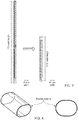
- FIG. 3 shows a comparison between the sub antennas being mounted in a longitudinal arrangement similar to that of Figure 1 and an arrangement according to an embodiment.
- the proposed design may also reduce the total number of handling and mounting parts and reduce the visual impact due to the length reduction.
- each sub antenna may be fixed to be horizontal or vertical depending on the azimuth angle or may vary according to the azimuth angle.
- the 2 sub antennas can radiate simultaneously with a high degree of signal isolation.
- the 2 considered frequency bands are: [2.5 GHz - 2.7 GHz] and [3.4 GHz - 3.6 GHz].
- Each sub antenna has its feeding network and radiating elements.
- the radiating elements are wrapped patches optimized according to each frequency band.
- the radiating elements are fed with equi amplitudes and equi phase rules.
- Antenna 2 is composed of a cylindrical hollow pipe (flexible material) having 0.8mm thickness (see figure 4 ).
- a brass part is provided inside the cylindrical hollow pipe, as shown in FIG 5 , to form the ground plane of the feeding network.
- the feeding part is composed of a T divider and capacitive coupling probe printed on a flexible thin PCB sheet (0.05 mm). As shown in Figure 6 , the feeding network is proposed to be wrapped on the upper face of the cylindrical pipe.
- the radiating elements are wrapped cylindrical patches using thin flexible PCB sheet (0.05 mm) rolled around the skeleton (see Figure 7 ) provided by the hollow pipe formed of the flexible material.
- the hollow pipe may have a cylindrical form, or the cross section may be some other curved form such as an ellipse.
- the antenna 2 can be viewed as being formed of one or more unitary cells each comprising a radiating element and feed network (see Figure 6 ). Where there are several of these they are arranged in series along the cylindrical hollow pipe as is shown in Figure 7 .
- the unitary cell is duplicated according to the target gain to be reached (10dBi peak gain).
- the target gain to be reached 10dBi peak gain.
- the internal sub antenna (antenna1) could be designed using 2 methods:
- antenna 1 unitary cell is duplicated according to the target gain to be reached (10dBi peak gain). We have used 10 patches for antenna 1.
- the antenna 1 position inside antenna 2 ( Figures 11A and 11B ) has been selected to reduce couplings between the 2 antennas and improve omnidirectional patterns for each frequency band.
- the antenna 1 (the internal one) has been:
- the resulting dual band antenna has a length of 0.75 m with preliminary good performances as set out in Figures 12 to 19 .
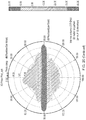
- Figure 12 shows preliminary results of how the gain achieved in dB changes with azimuth angle (phi) for antenna 2 operating at a frequency of 2.6GHz and with an elevation angle theta equal to 90°. It also shows an azimuth cut of the radiation pattern showing the omnidirectional nature of the antenna.
- Figure 13 shows similar results for antenna 1 operating at a frequency of 3.5 GHz and with an elevation angle theta equal to 90°.
- Figure 14 shows an elevation section of the achieved gain (in dB) at different azimuth angles of 0°, 45° and 90° for antenna 2, operating at a frequency of 2.6GHz.
- Figure 15 shows an elevation section of the achieved gain (in dB) at different azimuth angles 0°, 45° and 90° for antenna 1, operating at a frequency of 3.5 GHz.
- Figure 16 shows preliminary results for antenna 2 VSWR (voltage standing wave ratio), while Figure 17 shows the same thing for antenna 1.
- the Y axis is the VSWR and the flat line shows the specification which in this case is 1.5.
- Figure 18 shows the isolation between the two signals from the two sub antenna in dBs on the Y axis, while the flat line shows the specification which in this case is -30dB.
- Figures 19 - 21 show the radiation pattern at azimuth and elevation angles for the antenna.
- Figure 19 shows the radiation pattern for the outer sub antenna, antenna 2 while Figure 20 shows it for the inner sub antenna, antenna 1.
- Figure 21 shows the radiation pattern for the inner sub antenna, antenna 1 within the structure of the antenna.
- Figure 22 shows the difference in dimensions and corresponding wind loading between an antenna of the prior art and an antenna according to an embodiment with similar characteristics and performance.
- a sub antenna is an antenna, however, it is an antenna that is operable to radiate one signal and is located within the same radome as another sub antenna that is operable to radiate a different signal, the two sub antennas can be viewed as together forming an antenna.
- any block diagrams herein represent conceptual views of illustrative circuitry embodying the principles of the invention.
- any flow charts, flow diagrams, state transition diagrams, pseudo code, and the like represent various processes which may be substantially represented in computer readable medium and so executed by a computer or processor, whether or not such computer or processor is explicitly shown.
Landscapes
- Physics & Mathematics (AREA)
- Electromagnetism (AREA)
- Engineering & Computer Science (AREA)
- Computer Networks & Wireless Communication (AREA)
- Waveguide Aerials (AREA)
- Variable-Direction Aerials And Aerial Arrays (AREA)
Abstract
Description
- The field of the invention relates to antenna and in particular preferred embodiments to compact, quasi omnidirectional antenna with two sub antenna for radiating two different signals.
- Configuring a multi-directional or quasi-omnidirectional antenna, that is an antenna that seeks to radiate uniformly in all directions in one plane, with two sub antenna such that two independent signals can be radiated, in for example a dual band scenario, is challenging. The problems to be addressed are how to configure the antenna such that it can work simultaneously for both signals while:
- not unduly impacting RF performances of each signal
- not unduly increasing the overall width/profile of the antenna
- not unduly increasing the overall length of the antenna.
- Maintaining a compact antenna is important not only for visual considerations but also to allow it to withstand harsh conditions such as wind, gust effects and vibrations.
- An antenna with an increased gain is generally provided by increasing the overall length of the antenna in order to feed several radiating elements (patches/dipoles) in series. Where two sub antenna transmitting two different signals are to be used such as in a dual band operation, then for a better decoupling between the signals, the currently preferred architecture is presented in
Figure 1 (antenna 1 aboveantenna 2 inside the same radome). - Although this configuration may provide 2 sub-antennas that are well decoupled, the overall dual-band antenna length increases the risk of structural weakness and susceptibility to environmental conditions such as wind and gust effects.
- Another solution to reduce the global antenna length could be to place
antenna 1 next toantenna 2 as presented inFigure 2 . This solution has the drawbacks of an increased overall width and the added cost of a second radome. - It would be desirable to provide a compact antenna operable to radiate two signals in multiple directions without each unduly affecting the RF performance of the other.
- The first aspect of the present invention provides an antenna comprising: two sub antennas, each sub antenna comprising at least one radiating element, said two sub antennas comprise an inner sub antenna and an outer sub antenna; and signal feed circuitry for supplying a first signal to said inner sub antenna and signal feed circuitry for supply a second signal to said outer sub antenna; wherein said at least one radiating element of said outer sub antenna comprises at least one flexible radiating patch mounted on a flexible material arranged to wrap at least partially around at least a portion of said inner sub antenna.
- The problems associated with providing an antenna that has two sub antennas in a format that is compact such that visual pollution and robustness to harsh conditions such as strong winds are improved has been addressed by providing the two sub antennas as nested sub antennas one being provided within the other. This is made possible by the outer sub antenna being formed of one or more flexible radiating patches mounted on a flexible material that is arranged to wrap at least partially around a least a portion of the other sub antenna.
- The use of a flexible material for mounting the flexible radiating patch allows it to be wrapped into a curved hollow form such that it can surround another sub antenna and provide outwardly facing radiating elements allowing radiation to be emitted outwards from a surface at least partially surrounding the other antenna. Furthermore, by suitable selection of the flexible material, one that is substantially transparent to radio frequencies emitted by the inner sub antenna can be selected such that a nested antenna with good performance is provided. In this way a compact antenna is provided by the use of one or more hollow radiating elements that are able to wrap around the one or more radiating elements of another sub antenna.
- In some embodiments, said at least one flexible radiating patch is configured to wrap around at least 70% of an outer circumference of said inner antenna and in some embodiments around at least 80 or at least 95%.
- Having a radiating patch that wraps almost fully around the inner antenna provides a sub antenna that is effective in radiating in substantially all directions in one plane and is in effect a quasi-omnidirectional sub antenna.
- In some embodiments, said signal feed circuitry for each of said antennas comprises: signal supply circuitry running in a substantially longitudinal direction parallel to an axis of said antenna from a signal input; and at least one signal feed probe configured to capacitively couple said signal from said signal supply circuitry to a corresponding one of said at least one radiating patch.
- In some embodiments, said signal feed circuitry for said outer antenna comprises conductive tracks mounted on said flexible material.
- The signal feed circuitry for supplying the signal to the different radiating patches may be formed by a substantial longitudinal track running along the flexible material. This signal feed circuitry can be a cause of coupling between signals and as such limiting it to one longitudinal direction such that it can be appropriately shielded from, or arranged at a different circumferential position to, signal feed circuitry of the other sub antenna may reduce this coupling and be advantageous.
- In some embodiments, said inner and outer sub antenna are arranged such that they are rotated about said longitudinal axis with respect to each other, such that said signal supply circuitry of each sub antenna are at different circumferential position and do not overlap.
- As noted previously the signal supply circuitry may be a source of interference and coupling between the different antennas and where it is arranged along a longitudinal axis then it may be advantageous if the sub antenna are in effect rotated with respect to each other such that the signal supply circuitry are at different circumferential positions and do not overlap, i.e. they are not located on a common radius.
- In some embodiments, an input port to said signal feed circuitry of one sub antenna is at a different longitudinal end of said antenna to an input port to said signal feed circuitry of the other of said two sub antennas.
- A further way of reducing interference between the two sub antenna and any coupling between them is for the input port supplying the signal feed to the two different sub antennas to be located at different ends of the antenna. In effect one antenna is flipped around the horizontal axis compared to the other antenna.
- In some embodiments, said flexible material of said outer sub antenna comprises a conductive patch mounted on an inner surface of said flexible material, and said signal supply circuitry is mounted on an outer surface of said flexible material overlapping said conductive patch.
- In order to provide a ground plate for the signal supply circuitry and also to shield it from the inner sub antenna to some degree a conductive patch may be mounted on an inner surface of the flexible material. The conductive patch may extend across a portion of the circumference of the flexible material and along a portion of its length.
- In some embodiments, said at least one radiating element of said inner sub antenna comprises at least one flexible radiating patch mounted on a flexible material, said flexible material being arranged such that an outer perimeter of a cross section of said inner sub antenna comprises a curved surface.
- Although the inner antenna may have a number of forms, in some embodiments it too is formed from at least one flexible radiating patch mounted on a flexible material to form a curved surface. This fits neatly within the curved surface of the outer antenna and also may provide an effective omnidirectional or quasi-omnidirectional sub antenna.
- In some embodiments, said inner sub antenna has substantially the same architecture as said outer sub antenna and said flexible material of said inner sub antenna comprises a conductive patch mounted on an inner surface of said flexible material, and said signal feed circuitry for said sub antenna is mounted on an outer surface of said flexible material above said conductive patch.
- Although the inner antenna may have a different form to the outer sub antenna in some embodiments it has substantially the same form albeit physically smaller. In such an arrangement the conductive tracks forming the feed supply circuitry will be offset with respect to each other by rotation of one sub antenna with respect to the other.
- In other embodiments, said antenna comprises: a longitudinal conductive support member for supporting at least some components of said antenna; said signal feed circuitry for supplying a signal to said inner sub antenna comprising signal supply circuitry mounted on an outer surface of said inner longitudinal support member and configured to supply said signal to at least one signal feed probe configured to capacitively supply said signal to said at least one radiating element of said inner sub antenna; wherein said at least one radiating element comprises at least one radiating patch mounted on a flexible material said flexible material being mounted to at least partially wraparound said longitudinal support member.
- An alternative arrangement for the inner sub antenna is to have a curved radiating patch as the radiating element of the inner sub antenna but to mount this and the signal supply circuitry on a longitudinal conductive support member which acts both as a ground plane for the signal supply circuitry and as a central support for the whole antenna providing it with robustness and helping in problems arising due to harsh weather conditions.
- In some embodiments, each sub antenna comprises a plurality of radiating elements arranged subsequent to each other along a longitudinal axis.
- Although, the antenna may comprise sub antennas each with a single radiating element, in many embodiments they will have a plurality of radiating elements. The antenna may have a modular form with the number of radiating elements depending on the power and performance requirements. As these increase then the elements of the antenna may be duplicated along its longitudinal lengths and a longer, higher performance antenna is provided.
- In some embodiments, said two sub antennas are arranged such that said plurality of radiating elements of said two sub antennas are offset along said longitudinal axis with respect to each other.
- As noted previously, coupling between the radiating elements of the sub antenna is to be impeded where possible and one way of doing this is to arrange two sub antennas so that they are slightly offset with each other such that the radiating elements in the form of the flexible radiating patches are longitudinally offset with respect to each other. This helps reduce coupling between the two sub antennas and also may be advantageous for the inner sub antenna where it is in effect radiating through a gap between the radiating patches of the outer sub antenna.
- In some embodiments, said antenna comprises a dual band antenna and said radiating elements of said each of said two sub antennas are operable to radiate in a different one of said dual bands.
- Although the antenna may comprise a multi band antenna with the radiating elements of each of the two sub antennas radiating in the same frequency band but with a differently polarised signal, in some embodiments the two sub antennas operate in different frequency bands and the antenna provides a dual band antenna. The nested arrangements may be particularly effective for dual band antenna as the two sub antennas will naturally have a different size, one being within the other. A dual band antenna will have reduced interference between the signals as they operate in different frequency bands. Different polarisations of the two frequency bands could also be used to reduce interference further.
- In some embodiments, the antenna further comprises at least one further sub antenna mounted between said inner and said outer sub antenna.
- Although embodiments are applicable to two sub antennas nested within each other it should be clear to the skilled man that a plurality of sub antennas could be arranged in this way, one within the other to provide a particularly compact multiple frequency band or multiple band antenna.
- In some embodiments, said antenna comprises a quasi-omnidirectional antenna configured to radiate in substantially all directions in one plane.
- This configuration is particularly applicable to a quasi-omnidirectional antenna which is configured to radiate substantially uniformly in all directions. Such an antenna does not have reflective portions and as of such lends itself well to this nested arrangement particularly where hollow flexible radiating patches are used as the radiating element(s).
- Further particular and preferred aspects are set out in the accompanying independent and dependent claims. Features of the dependent claims may be combined with features of the independent claims as appropriate, and in combinations other than those explicitly set out in the claims.
- Where an apparatus feature is described as being operable to provide a function, it will be appreciated that this includes an apparatus feature which provides that function or which is adapted or configured to provide that function.
- Embodiments of the present invention will now be described further, with reference to the accompanying drawings, in which:
-
Figure 1 shows an antenna comprising sub antennas arranged one above the other according to the prior art; -
Figure 2 shows an antenna comprising two sub antennas arranged side by side according to the prior art; -
Figure 3 shows differences in length between a prior art antenna and one according to an embodiment; -
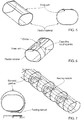
Figure 4 shows schematically the flexible material forming the support for the radiating patch; -
Figure 5 shows the flexible material with the ground conductive plate on it; -
Figure 6 shows the flexible material with the ground conductive plate and signal feed circuitry on it; -
Figure 7 shows the flexible material with the radiating patches and signal feeding network mounted on it; -
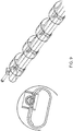
Figure 8 shows how the plurality of these components are wrapped to form one of the sub antenna; -
Figure 9 shows two corresponding sub antennas of a same formation but of different circumferences mounted one within the other; -
Figure 10 shows a different form of internal sub antenna; -
Figures 11A and B shows an inner sub antenna inside an outer sub antennas where positions have been selected to reduce coupling between the two sub antennas; -
Figures 12 - 18 show example performance data for such antenna; -
Figures 19 - 21 show example radiation patterns for such antenna; and -
Figure 22 shows the difference in dimensions of an antenna according to the prior art and one according to an embodiment. - Before discussing the embodiments in any more detail, first an overview will be provided.
- Embodiments provide a compact antenna formed of sub antennas nested one inside the other. In some embodiments, each sub antenna has radiating elements with curved surfaces such that each emits omnidirectional or quasi omnidirectional radiation.
- The inner and outer sub antennas may have the same form although different physical sizes or the inner sub antenna may be formed around a central conductive supporting member which may form the ground plane for the signal supply circuitry of this sub antenna. In other embodiments the ground plane for the signal supply circuitry may be formed as a brass conductive layer on the internal surface of the flexible material holding the flexible radiation patches. In order to reduce coupling and increase isolation between the two sub antennas the two sub antennas can be flipped with regard to each other on the three axes.
- Thus, they can be rotated around the Z axis to a selected angle to reduce coupling between the signals, such that the two signal feed circuitries are not aligned. They may be moved along the Z axis with a particular shift to provide a longitudinal offset between the radiating patches and one of the sub antennas may be flipped with respect to the other about the Z axis such that the feed inputs are at different ends of the antenna.
- Embodiments seek to create a compact, low length, high gain dual-band quasi-omnidirectional antenna.
- Instead of superimposing two omnidirectional sub antennas longitudinally on top of each other, the idea is to have one omnidirectional sub antenna placed inside the other (
antenna 1 inside antenna 2). In the context of omnidirectional antennas, placing one sub antenna inside the other (concentric design) will increase the coupling between the 2 sub antennas and decrease the RF performances ([S] parameters and radiation patterns). To address these issues, the antenna 1 (the internal one) has in some embodiments been: - flipped versus
antenna 2 on the 3 axis (X,Y,Z). - rotated versus
antenna 2 around the Z-axis with an optimized or at least preferred angle. - moved along the Z-axis inside
antenna 2 with an optimized or at least preferred shift. - It is proposed in one embodiment that the radiating elements are wrapped around the antenna structure, the antenna structure forming a central support rod type structure. In some embodiments, the feeding network is also proposed to be wrapped around the antenna structure.
- Where the antenna is a dual band antenna, the inner sub antenna,
antenna 1 corresponds to the high band frequency range due to its smaller dimensions. The outer sub antenna,antenna 2 corresponds to the lower band frequency range. - In some embodiments there may be further sub antenna wrapped around each other, the outer antenna transmitting at lower band frequencies than the inner antenna.
- In some embodiments the antenna may be a multi-band antenna with the two sub antenna transmitting in the same frequency band.
- In some embodiments, each sub antenna may transmit with differently polarized signals.
- This concentric design with a specific internal sub antenna configuration allows a significant reduction in length while keeping the same antenna width when compared to similar antenna of the prior art without compromising on RF performance.
Figure 3 shows a comparison between the sub antennas being mounted in a longitudinal arrangement similar to that ofFigure 1 and an arrangement according to an embodiment. The proposed design may also reduce the total number of handling and mounting parts and reduce the visual impact due to the length reduction. - The polarization of each sub antenna may be fixed to be horizontal or vertical depending on the azimuth angle or may vary according to the azimuth angle.
- This design is described here for a concentric high gain dual-band omnidirectional antenna, however the skilled person would understand that it could be extended to concentric multi-band omnidirectional antennas where each sub antenna is configured to operate in the same frequency band but is fed with different signals, these signals being differently polarized to reduce coupling and interference between the signals.
- In this section, for a practical example, 2 concentric high gain quasi omnidirectional sub antennas will be described. The 2 sub antennas can radiate simultaneously with a high degree of signal isolation.
- The 2 considered frequency bands are: [2.5 GHz - 2.7 GHz] and [3.4 GHz - 3.6 GHz].
- Antenna 1: the internal sub antenna designed for [3.4 GHz - 3.6 GHz] frequency band.
- Antenna 2: the external sub antenna designed for [2.5 GHz - 2.7 GHz] frequency band.
- Each sub antenna has its feeding network and radiating elements.
- For both sub antennas the radiating elements are wrapped patches optimized according to each frequency band.
- In this example, we consider that:
- spacing between "
antenna 1" patches = spacing between "antenna 2" patches = d = 60 mm. - d @ 2.7 GHz = 0.54 λ.
- d @ 3.6 GHz = 0.70 λ.
- The radiating elements are fed with equi amplitudes and equi phase rules.
- The feeding network of
antenna 1 is formed on aflexible material 1 having a relative permittivity Dk1=2.25. - The feeding network of
antenna 2 is formed on aflexible material 2 having a relative permittivity Dk2=4.50. -
Antenna 2 is composed of a cylindrical hollow pipe (flexible material) having 0.8mm thickness (seefigure 4 ). - A brass part is provided inside the cylindrical hollow pipe, as shown in
FIG 5 , to form the ground plane of the feeding network. - The feeding part is composed of a T divider and capacitive coupling probe printed on a flexible thin PCB sheet (0.05 mm). As shown in
Figure 6 , the feeding network is proposed to be wrapped on the upper face of the cylindrical pipe. - The radiating elements are wrapped cylindrical patches using thin flexible PCB sheet (0.05 mm) rolled around the skeleton (see
Figure 7 ) provided by the hollow pipe formed of the flexible material. The hollow pipe may have a cylindrical form, or the cross section may be some other curved form such as an ellipse. Theantenna 2 can be viewed as being formed of one or more unitary cells each comprising a radiating element and feed network (seeFigure 6 ). Where there are several of these they are arranged in series along the cylindrical hollow pipe as is shown inFigure 7 . - The unitary cell is duplicated according to the target gain to be reached (10dBi peak gain). In our example, taking into account the losses associated with the PCB that is used (Dk =4.5) and the spacing between patches (0.54 λ), we have used 12 patches for antenna 2 (see
Figure 8 ) which we estimate should provide the target gain. - The internal sub antenna (antenna1) could be designed using 2 methods:
- Method 1: The same design as antenna 2: both feeding network and radiating elements are wrapped (see
Figure 9 ). - Method 2: An alternative design: (see
Figure 10 ).
In this design the internal antenna,antenna 1 comprises a central U-shaped metallic rod that provides support for many of the other components of the internal sub antenna as well as providing a ground plane. Radiating patches are wrapped around the central structure which comprises signal feed probe(s) for providing the signal to the radiating patch(es). These signal feed probes are formed on a single PCB which runs along the length of the antenna. Clips are provided periodically along the length of the signal feed probe PCB and the U-shaped metallic rod is held in position in U-shaped recesses within the clips.
A second PCB is used as signal supply circuitry to supply a signal to the signal feed probe(s) mounted on an outer surface of the U-shaped rod and locked in place by resilient closure members which attach to the plastic clips. The closure member portion of the clip is slid inside the lower plastic part of the clip, and exerts pressure between the feeding PCB and the U shaped rod. As a result, grounding of the PCB is provided by the metallic rod and the space available inside this U-shaped rod can be used for the input signal cable where required. - Again the
antenna 1 unitary cell is duplicated according to the target gain to be reached (10dBi peak gain). We have used 10 patches forantenna 1. - The
antenna 1 position inside antenna 2 (Figures 11A and 11B ) has been selected to reduce couplings between the 2 antennas and improve omnidirectional patterns for each frequency band. - In this proposed solution, the antenna 1 (the internal one) has been:
- flipped versus
antenna 2 on the 3 axis (X,Y,Z). - rotated versus
antenna 2 around Z-axis with an optimized angle. - moved along the Z-axis inside
antenna 2 with an optimized shift. - The resulting dual band antenna has a length of 0.75 m with preliminary good performances as set out in
Figures 12 to 19 . -
Figure 12 shows preliminary results of how the gain achieved in dB changes with azimuth angle (phi) forantenna 2 operating at a frequency of 2.6GHz and with an elevation angle theta equal to 90°. It also shows an azimuth cut of the radiation pattern showing the omnidirectional nature of the antenna. -
Figure 13 shows similar results forantenna 1 operating at a frequency of 3.5 GHz and with an elevation angle theta equal to 90°. -
Figure 14 shows an elevation section of the achieved gain (in dB) at different azimuth angles of 0°, 45° and 90° forantenna 2, operating at a frequency of 2.6GHz. -
Figure 15 shows an elevation section of the achieved gain (in dB) atdifferent azimuth angles 0°, 45° and 90° forantenna 1, operating at a frequency of 3.5 GHz. -
Figure 16 shows preliminary results forantenna 2 VSWR (voltage standing wave ratio), whileFigure 17 shows the same thing forantenna 1. In this example the Y axis is the VSWR and the flat line shows the specification which in this case is 1.5. -
Figure 18 shows the isolation between the two signals from the two sub antenna in dBs on the Y axis, while the flat line shows the specification which in this case is -30dB. -
Figures 19 - 21 show the radiation pattern at azimuth and elevation angles for the antenna. -
Figure 19 shows the radiation pattern for the outer sub antenna,antenna 2 whileFigure 20 shows it for the inner sub antenna,antenna 1.Figure 21 shows the radiation pattern for the inner sub antenna,antenna 1 within the structure of the antenna. -
Figure 22 shows the difference in dimensions and corresponding wind loading between an antenna of the prior art and an antenna according to an embodiment with similar characteristics and performance. - It should be noted that in the context of this application a sub antenna is an antenna, however, it is an antenna that is operable to radiate one signal and is located within the same radome as another sub antenna that is operable to radiate a different signal, the two sub antennas can be viewed as together forming an antenna.
- It should be appreciated by those skilled in the art that any block diagrams herein represent conceptual views of illustrative circuitry embodying the principles of the invention. Similarly, it will be appreciated that any flow charts, flow diagrams, state transition diagrams, pseudo code, and the like represent various processes which may be substantially represented in computer readable medium and so executed by a computer or processor, whether or not such computer or processor is explicitly shown.
- The description and drawings merely illustrate the principles of the invention. It will thus be appreciated that those skilled in the art will be able to devise various arrangements that, although not explicitly described or shown herein, embody the principles of the invention and are included within its spirit and scope. Furthermore, all examples recited herein are principally intended expressly to be only for pedagogical purposes to aid the reader in understanding the principles of the invention and the concepts contributed by the inventor(s) to furthering the art, and are to be construed as being without limitation to such specifically recited examples and conditions. Moreover, all statements herein reciting principles, aspects, and embodiments of the invention, as well as specific examples thereof, are intended to encompass equivalents thereof.
Claims (15)
- An antenna comprising:two sub antennas, each sub antenna comprising at least one radiating element, said two sub antennas comprising an inner sub antenna and an outer sub antenna; andsignal feed circuitry for supplying a first signal to said inner sub antenna and signal feed circuitry for supply a second signal to said outer sub antenna; whereinsaid at least one radiating element of said outer sub antenna comprises at least one flexible radiating patch mounted on a flexible material arranged to wrap at least partially around at least a portion of said inner sub antenna.
- An antenna according to claim 1, wherein said at least one flexible radiating patch is configured to wrap around at least 70% of an outer circumference of said inner antenna.
- An antenna according to any preceding claim, wherein said signal feed circuitry for each of said antenna comprises:signal supply circuitry running in a substantially longitudinal direction parallel to an axis of said antenna from a signal input; andat least one signal feed probe configured to capacitively couple said signal from said signal supply circuitry to a corresponding one of said at least one radiating patch.
- An antenna according to claim 3, wherein said signal feed circuitry for said outer sub antenna comprises conductive tracks mounted on said flexible material.
- An antenna according to any one of claims 3 or 4, wherein said inner and outer sub antenna are arranged such that said signal supply circuitry of each sub antenna are at different circumferential positions and do not overlap.
- An antenna according to any preceding claim, wherein an input port to said signal feed circuitry of one sub antenna is at a different longitudinal end of said antenna to an input port to said signal feed circuitry of the other of said two sub antennas.
- An antenna according to any preceding claim, wherein said flexible material of said outer sub antenna comprises a conductive patch mounted on an inner surface of said flexible material, and said signal supply circuitry is mounted on an outer surface of said flexible material overlying said conductive patch.
- An antenna according to any preceding claim, wherein said at least one radiating element of said inner sub antenna comprises at least one flexible radiating patch mounted on a flexible material, said flexible material being arranged such that an outer perimeter of a cross section of said inner sub antenna comprises a curved surface.
- An antenna according to claims 7 and 8, wherein said inner sub antenna has substantially the same architecture as said outer antenna and said flexible material of said inner sub antenna comprises a conductive patch mounted on an inner surface of said flexible material, and said signal feed circuitry for said sub antenna is mounted on an outer surface of said flexible material overlying said conductive patch.
- An antenna according to any one of claims 1 to 7, wherein said antenna comprises:a longitudinal conductive support member for supporting at least some components of said antenna;said signal feed circuitry for supplying a signal to said inner sub antenna comprises signal supply circuitry mounted on an outer surface of said inner longitudinal support member and configured to supply said signal to at least one signal feed probe configured to capacitively supply said signal to said at least one radiating element of said inner sub antenna; whereinsaid at least one radiating element comprises at least one radiating patch mounted on a flexible material said flexible material being mounted to at least partially wraparound said longitudinal support member.
- An antenna according to any preceding claim, wherein each sub antenna comprises a plurality of radiating elements arranged subsequent to each other along a longitudinal axis.
- An antenna according to claim 11, wherein said two sub antennas are arranged such that said plurality of radiating elements of said two sub antennas are offset along said longitudinal axis with respect to each other.
- An antenna according to any preceding claim, wherein said antenna comprises a dual band antenna and said radiating elements of said each of said two sub antennas are operable to radiate in a different one of said dual bands.
- An antenna according to any one of claims 1 to 13, comprising at least one further sub antenna mounted between said inner and said outer sub antennas.
- An antenna according to any one of claims 1 to 14, wherein said antenna comprises a quasi-omni directional antenna configured to radiate in all directions in one plane.
Priority Applications (3)
| Application Number | Priority Date | Filing Date | Title |
|---|---|---|---|
| EP17306316.5A EP3462536B1 (en) | 2017-10-02 | 2017-10-02 | Compact antenna |
| PCT/CN2018/107858 WO2019068248A1 (en) | 2017-10-02 | 2018-09-27 | Compact antenna |
| US16/652,454 US11482796B2 (en) | 2017-10-02 | 2018-09-27 | Compact antenna |
Applications Claiming Priority (1)
| Application Number | Priority Date | Filing Date | Title |
|---|---|---|---|
| EP17306316.5A EP3462536B1 (en) | 2017-10-02 | 2017-10-02 | Compact antenna |
Publications (2)
| Publication Number | Publication Date |
|---|---|
| EP3462536A1 true EP3462536A1 (en) | 2019-04-03 |
| EP3462536B1 EP3462536B1 (en) | 2021-06-30 |
Family
ID=60302030
Family Applications (1)
| Application Number | Title | Priority Date | Filing Date |
|---|---|---|---|
| EP17306316.5A Active EP3462536B1 (en) | 2017-10-02 | 2017-10-02 | Compact antenna |
Country Status (3)
| Country | Link |
|---|---|
| US (1) | US11482796B2 (en) |
| EP (1) | EP3462536B1 (en) |
| WO (1) | WO2019068248A1 (en) |
Citations (4)
| Publication number | Priority date | Publication date | Assignee | Title |
|---|---|---|---|---|
| EP0856906A2 (en) * | 1997-02-04 | 1998-08-05 | ICO Services Ltd. | Antenna and fabrication method |
| US6285322B1 (en) * | 1997-01-03 | 2001-09-04 | Telefonaktiebolaget Lm Ericsson (Publ) | Electronics unit for wireless transfer of signals |
| US20120188137A1 (en) * | 2008-03-21 | 2012-07-26 | Farzin Lalezari | Broadband antenna system allowing multiple stacked collinear devices and having an integrated, co-planar balun |
| US20170062917A1 (en) * | 2015-08-28 | 2017-03-02 | Huawei Technologies Co., Ltd | Multi-filar helical antenna |
Family Cites Families (6)
| Publication number | Priority date | Publication date | Assignee | Title |
|---|---|---|---|---|
| JP3399513B2 (en) | 1999-08-10 | 2003-04-21 | 日本電気株式会社 | Helical antenna and manufacturing method thereof |
| US6664932B2 (en) * | 2000-01-12 | 2003-12-16 | Emag Technologies, Inc. | Multifunction antenna for wireless and telematic applications |
| US6947008B2 (en) * | 2003-01-31 | 2005-09-20 | Ems Technologies, Inc. | Conformable layered antenna array |
| FR2906085B1 (en) | 2006-09-20 | 2010-06-04 | Radiall Sa | WIDE BAND ADAPTATION ANTENNA |
| GB0905769D0 (en) * | 2009-04-03 | 2009-05-20 | Siemens Ag | Microwave connection |
| DE102010011867B4 (en) * | 2010-03-18 | 2011-12-22 | Kathrein-Werke Kg | Broadband omnidirectional antenna |
-
2017
- 2017-10-02 EP EP17306316.5A patent/EP3462536B1/en active Active
-
2018
- 2018-09-27 US US16/652,454 patent/US11482796B2/en active Active
- 2018-09-27 WO PCT/CN2018/107858 patent/WO2019068248A1/en not_active Ceased
Patent Citations (4)
| Publication number | Priority date | Publication date | Assignee | Title |
|---|---|---|---|---|
| US6285322B1 (en) * | 1997-01-03 | 2001-09-04 | Telefonaktiebolaget Lm Ericsson (Publ) | Electronics unit for wireless transfer of signals |
| EP0856906A2 (en) * | 1997-02-04 | 1998-08-05 | ICO Services Ltd. | Antenna and fabrication method |
| US20120188137A1 (en) * | 2008-03-21 | 2012-07-26 | Farzin Lalezari | Broadband antenna system allowing multiple stacked collinear devices and having an integrated, co-planar balun |
| US20170062917A1 (en) * | 2015-08-28 | 2017-03-02 | Huawei Technologies Co., Ltd | Multi-filar helical antenna |
Also Published As
| Publication number | Publication date |
|---|---|
| WO2019068248A1 (en) | 2019-04-11 |
| EP3462536B1 (en) | 2021-06-30 |
| US20200235482A1 (en) | 2020-07-23 |
| US11482796B2 (en) | 2022-10-25 |
Similar Documents
| Publication | Publication Date | Title |
|---|---|---|
| JP5721810B2 (en) | Cross-polarized multiband antenna | |
| US8742990B2 (en) | Circular polarization antenna | |
| CN109687116B (en) | C-band miniaturized broadband wide-beam circularly polarized microstrip antenna | |
| CN106450690B (en) | Low profile overlay antenna | |
| JP5956582B2 (en) | antenna | |
| JP5357274B2 (en) | Planar antenna and related methods | |
| US8866689B2 (en) | Multi-band antenna and methods for long term evolution wireless system | |
| EP2999046B1 (en) | Multi-antenna system and mobile terminal | |
| JP2008178101A (en) | Dual-polarization, slot-mode antenna and associated methods | |
| US8791865B2 (en) | Multi-loop antenna system and electronic apparatus having the same | |
| US20100182203A1 (en) | Broadband antenna for wireless communications | |
| KR20130134793A (en) | Dual polarization dipole antenna for dual-band and antenna array using it | |
| CN101834345A (en) | Ultra-wide band antenna and single-polarized and dual-polarized radiating elements thereof | |
| US20130120209A1 (en) | Systems and methods providing planar antennas including reflectors | |
| US20200127388A1 (en) | Antenna structure and electronic device | |
| WO2016138763A1 (en) | Dual-polarized antenna | |
| US20250323416A1 (en) | Lowband dipole with improved gain and isolation | |
| US20120133559A1 (en) | Compact multibeam antenna | |
| US20170062917A1 (en) | Multi-filar helical antenna | |
| CN207353459U (en) | Antenna element and aerial array | |
| CN107611606A (en) | Antenna structure and terminal | |
| CN113871883A (en) | A Metamaterial Antenna for RCS Reduction of Microstrip Antennas | |
| Zhou et al. | An omnidirectional vertical-polarized C-V2X antenna with high gain and low profile | |
| CN217062519U (en) | Small cylindrical conformal antenna | |
| US11482796B2 (en) | Compact antenna |
Legal Events
| Date | Code | Title | Description |
|---|---|---|---|
| PUAI | Public reference made under article 153(3) epc to a published international application that has entered the european phase |
Free format text: ORIGINAL CODE: 0009012 |
|
| STAA | Information on the status of an ep patent application or granted ep patent |
Free format text: STATUS: THE APPLICATION HAS BEEN PUBLISHED |
|
| AK | Designated contracting states |
Kind code of ref document: A1 Designated state(s): AL AT BE BG CH CY CZ DE DK EE ES FI FR GB GR HR HU IE IS IT LI LT LU LV MC MK MT NL NO PL PT RO RS SE SI SK SM TR |
|
| AX | Request for extension of the european patent |
Extension state: BA ME |
|
| STAA | Information on the status of an ep patent application or granted ep patent |
Free format text: STATUS: REQUEST FOR EXAMINATION WAS MADE |
|
| STAA | Information on the status of an ep patent application or granted ep patent |
Free format text: STATUS: EXAMINATION IS IN PROGRESS |
|
| 17P | Request for examination filed |
Effective date: 20191004 |
|
| RBV | Designated contracting states (corrected) |
Designated state(s): AL AT BE BG CH CY CZ DE DK EE ES FI FR GB GR HR HU IE IS IT LI LT LU LV MC MK MT NL NO PL PT RO RS SE SI SK SM TR |
|
| 17Q | First examination report despatched |
Effective date: 20191031 |
|
| RIC1 | Information provided on ipc code assigned before grant |
Ipc: H01Q 9/04 20060101ALI20201210BHEP Ipc: H01Q 21/08 20060101ALI20201210BHEP Ipc: H01Q 1/24 20060101AFI20201210BHEP Ipc: H01Q 21/06 20060101ALN20201210BHEP Ipc: H01Q 1/38 20060101ALI20201210BHEP Ipc: H01Q 5/42 20150101ALI20201210BHEP |
|
| GRAP | Despatch of communication of intention to grant a patent |
Free format text: ORIGINAL CODE: EPIDOSNIGR1 |
|
| STAA | Information on the status of an ep patent application or granted ep patent |
Free format text: STATUS: GRANT OF PATENT IS INTENDED |
|
| INTG | Intention to grant announced |
Effective date: 20210115 |
|
| GRAS | Grant fee paid |
Free format text: ORIGINAL CODE: EPIDOSNIGR3 |
|
| GRAA | (expected) grant |
Free format text: ORIGINAL CODE: 0009210 |
|
| STAA | Information on the status of an ep patent application or granted ep patent |
Free format text: STATUS: THE PATENT HAS BEEN GRANTED |
|
| AK | Designated contracting states |
Kind code of ref document: B1 Designated state(s): AL AT BE BG CH CY CZ DE DK EE ES FI FR GB GR HR HU IE IS IT LI LT LU LV MC MK MT NL NO PL PT RO RS SE SI SK SM TR |
|
| REG | Reference to a national code |
Ref country code: CH Ref legal event code: EP |
|
| REG | Reference to a national code |
Ref country code: AT Ref legal event code: REF Ref document number: 1407204 Country of ref document: AT Kind code of ref document: T Effective date: 20210715 |
|
| REG | Reference to a national code |
Ref country code: DE Ref legal event code: R096 Ref document number: 602017041161 Country of ref document: DE |
|
| REG | Reference to a national code |
Ref country code: IE Ref legal event code: FG4D |
|
| REG | Reference to a national code |
Ref country code: LT Ref legal event code: MG9D |
|
| PG25 | Lapsed in a contracting state [announced via postgrant information from national office to epo] |
Ref country code: FI Free format text: LAPSE BECAUSE OF FAILURE TO SUBMIT A TRANSLATION OF THE DESCRIPTION OR TO PAY THE FEE WITHIN THE PRESCRIBED TIME-LIMIT Effective date: 20210630 Ref country code: HR Free format text: LAPSE BECAUSE OF FAILURE TO SUBMIT A TRANSLATION OF THE DESCRIPTION OR TO PAY THE FEE WITHIN THE PRESCRIBED TIME-LIMIT Effective date: 20210630 Ref country code: BG Free format text: LAPSE BECAUSE OF FAILURE TO SUBMIT A TRANSLATION OF THE DESCRIPTION OR TO PAY THE FEE WITHIN THE PRESCRIBED TIME-LIMIT Effective date: 20210930 |
|
| REG | Reference to a national code |
Ref country code: NL Ref legal event code: MP Effective date: 20210630 |
|
| REG | Reference to a national code |
Ref country code: AT Ref legal event code: MK05 Ref document number: 1407204 Country of ref document: AT Kind code of ref document: T Effective date: 20210630 |
|
| PG25 | Lapsed in a contracting state [announced via postgrant information from national office to epo] |
Ref country code: SE Free format text: LAPSE BECAUSE OF FAILURE TO SUBMIT A TRANSLATION OF THE DESCRIPTION OR TO PAY THE FEE WITHIN THE PRESCRIBED TIME-LIMIT Effective date: 20210630 Ref country code: RS Free format text: LAPSE BECAUSE OF FAILURE TO SUBMIT A TRANSLATION OF THE DESCRIPTION OR TO PAY THE FEE WITHIN THE PRESCRIBED TIME-LIMIT Effective date: 20210630 Ref country code: NO Free format text: LAPSE BECAUSE OF FAILURE TO SUBMIT A TRANSLATION OF THE DESCRIPTION OR TO PAY THE FEE WITHIN THE PRESCRIBED TIME-LIMIT Effective date: 20210930 Ref country code: GR Free format text: LAPSE BECAUSE OF FAILURE TO SUBMIT A TRANSLATION OF THE DESCRIPTION OR TO PAY THE FEE WITHIN THE PRESCRIBED TIME-LIMIT Effective date: 20211001 Ref country code: LV Free format text: LAPSE BECAUSE OF FAILURE TO SUBMIT A TRANSLATION OF THE DESCRIPTION OR TO PAY THE FEE WITHIN THE PRESCRIBED TIME-LIMIT Effective date: 20210630 |
|
| PG25 | Lapsed in a contracting state [announced via postgrant information from national office to epo] |
Ref country code: SK Free format text: LAPSE BECAUSE OF FAILURE TO SUBMIT A TRANSLATION OF THE DESCRIPTION OR TO PAY THE FEE WITHIN THE PRESCRIBED TIME-LIMIT Effective date: 20210630 Ref country code: SM Free format text: LAPSE BECAUSE OF FAILURE TO SUBMIT A TRANSLATION OF THE DESCRIPTION OR TO PAY THE FEE WITHIN THE PRESCRIBED TIME-LIMIT Effective date: 20210630 Ref country code: AT Free format text: LAPSE BECAUSE OF FAILURE TO SUBMIT A TRANSLATION OF THE DESCRIPTION OR TO PAY THE FEE WITHIN THE PRESCRIBED TIME-LIMIT Effective date: 20210630 Ref country code: CZ Free format text: LAPSE BECAUSE OF FAILURE TO SUBMIT A TRANSLATION OF THE DESCRIPTION OR TO PAY THE FEE WITHIN THE PRESCRIBED TIME-LIMIT Effective date: 20210630 Ref country code: EE Free format text: LAPSE BECAUSE OF FAILURE TO SUBMIT A TRANSLATION OF THE DESCRIPTION OR TO PAY THE FEE WITHIN THE PRESCRIBED TIME-LIMIT Effective date: 20210630 Ref country code: NL Free format text: LAPSE BECAUSE OF FAILURE TO SUBMIT A TRANSLATION OF THE DESCRIPTION OR TO PAY THE FEE WITHIN THE PRESCRIBED TIME-LIMIT Effective date: 20210630 Ref country code: PT Free format text: LAPSE BECAUSE OF FAILURE TO SUBMIT A TRANSLATION OF THE DESCRIPTION OR TO PAY THE FEE WITHIN THE PRESCRIBED TIME-LIMIT Effective date: 20211102 Ref country code: RO Free format text: LAPSE BECAUSE OF FAILURE TO SUBMIT A TRANSLATION OF THE DESCRIPTION OR TO PAY THE FEE WITHIN THE PRESCRIBED TIME-LIMIT Effective date: 20210630 Ref country code: ES Free format text: LAPSE BECAUSE OF FAILURE TO SUBMIT A TRANSLATION OF THE DESCRIPTION OR TO PAY THE FEE WITHIN THE PRESCRIBED TIME-LIMIT Effective date: 20210630 |
|
| PG25 | Lapsed in a contracting state [announced via postgrant information from national office to epo] |
Ref country code: PL Free format text: LAPSE BECAUSE OF FAILURE TO SUBMIT A TRANSLATION OF THE DESCRIPTION OR TO PAY THE FEE WITHIN THE PRESCRIBED TIME-LIMIT Effective date: 20210630 |
|
| REG | Reference to a national code |
Ref country code: DE Ref legal event code: R097 Ref document number: 602017041161 Country of ref document: DE |
|
| PG25 | Lapsed in a contracting state [announced via postgrant information from national office to epo] |
Ref country code: DK Free format text: LAPSE BECAUSE OF FAILURE TO SUBMIT A TRANSLATION OF THE DESCRIPTION OR TO PAY THE FEE WITHIN THE PRESCRIBED TIME-LIMIT Effective date: 20210630 |
|
| PLBE | No opposition filed within time limit |
Free format text: ORIGINAL CODE: 0009261 |
|
| STAA | Information on the status of an ep patent application or granted ep patent |
Free format text: STATUS: NO OPPOSITION FILED WITHIN TIME LIMIT |
|
| REG | Reference to a national code |
Ref country code: CH Ref legal event code: PL |
|
| PG25 | Lapsed in a contracting state [announced via postgrant information from national office to epo] |
Ref country code: AL Free format text: LAPSE BECAUSE OF FAILURE TO SUBMIT A TRANSLATION OF THE DESCRIPTION OR TO PAY THE FEE WITHIN THE PRESCRIBED TIME-LIMIT Effective date: 20210630 |
|
| 26N | No opposition filed |
Effective date: 20220331 |
|
| REG | Reference to a national code |
Ref country code: BE Ref legal event code: MM Effective date: 20211031 |
|
| PG25 | Lapsed in a contracting state [announced via postgrant information from national office to epo] |
Ref country code: MC Free format text: LAPSE BECAUSE OF FAILURE TO SUBMIT A TRANSLATION OF THE DESCRIPTION OR TO PAY THE FEE WITHIN THE PRESCRIBED TIME-LIMIT Effective date: 20210630 |
|
| PG25 | Lapsed in a contracting state [announced via postgrant information from national office to epo] |
Ref country code: LU Free format text: LAPSE BECAUSE OF NON-PAYMENT OF DUE FEES Effective date: 20211002 Ref country code: IT Free format text: LAPSE BECAUSE OF FAILURE TO SUBMIT A TRANSLATION OF THE DESCRIPTION OR TO PAY THE FEE WITHIN THE PRESCRIBED TIME-LIMIT Effective date: 20210630 Ref country code: BE Free format text: LAPSE BECAUSE OF NON-PAYMENT OF DUE FEES Effective date: 20211031 |
|
| PG25 | Lapsed in a contracting state [announced via postgrant information from national office to epo] |
Ref country code: LI Free format text: LAPSE BECAUSE OF NON-PAYMENT OF DUE FEES Effective date: 20211031 Ref country code: CH Free format text: LAPSE BECAUSE OF NON-PAYMENT OF DUE FEES Effective date: 20211031 |
|
| PG25 | Lapsed in a contracting state [announced via postgrant information from national office to epo] |
Ref country code: IE Free format text: LAPSE BECAUSE OF NON-PAYMENT OF DUE FEES Effective date: 20211002 |
|
| PG25 | Lapsed in a contracting state [announced via postgrant information from national office to epo] |
Ref country code: LT Free format text: LAPSE BECAUSE OF FAILURE TO SUBMIT A TRANSLATION OF THE DESCRIPTION OR TO PAY THE FEE WITHIN THE PRESCRIBED TIME-LIMIT Effective date: 20210630 |
|
| PG25 | Lapsed in a contracting state [announced via postgrant information from national office to epo] |
Ref country code: CY Free format text: LAPSE BECAUSE OF FAILURE TO SUBMIT A TRANSLATION OF THE DESCRIPTION OR TO PAY THE FEE WITHIN THE PRESCRIBED TIME-LIMIT Effective date: 20210630 |
|
| PG25 | Lapsed in a contracting state [announced via postgrant information from national office to epo] |
Ref country code: HU Free format text: LAPSE BECAUSE OF FAILURE TO SUBMIT A TRANSLATION OF THE DESCRIPTION OR TO PAY THE FEE WITHIN THE PRESCRIBED TIME-LIMIT; INVALID AB INITIO Effective date: 20171002 |
|
| PGFP | Annual fee paid to national office [announced via postgrant information from national office to epo] |
Ref country code: GB Payment date: 20230831 Year of fee payment: 7 |
|
| PGFP | Annual fee paid to national office [announced via postgrant information from national office to epo] |
Ref country code: FR Payment date: 20230911 Year of fee payment: 7 |
|
| PGFP | Annual fee paid to national office [announced via postgrant information from national office to epo] |
Ref country code: DE Payment date: 20230830 Year of fee payment: 7 |
|
| PG25 | Lapsed in a contracting state [announced via postgrant information from national office to epo] |
Ref country code: MK Free format text: LAPSE BECAUSE OF FAILURE TO SUBMIT A TRANSLATION OF THE DESCRIPTION OR TO PAY THE FEE WITHIN THE PRESCRIBED TIME-LIMIT Effective date: 20210630 |
|
| PG25 | Lapsed in a contracting state [announced via postgrant information from national office to epo] |
Ref country code: MT Free format text: LAPSE BECAUSE OF FAILURE TO SUBMIT A TRANSLATION OF THE DESCRIPTION OR TO PAY THE FEE WITHIN THE PRESCRIBED TIME-LIMIT Effective date: 20210630 |
|
| REG | Reference to a national code |
Ref country code: DE Ref legal event code: R119 Ref document number: 602017041161 Country of ref document: DE |
|
| GBPC | Gb: european patent ceased through non-payment of renewal fee |
Effective date: 20241002 |
|
| PG25 | Lapsed in a contracting state [announced via postgrant information from national office to epo] |
Ref country code: DE Free format text: LAPSE BECAUSE OF NON-PAYMENT OF DUE FEES Effective date: 20250501 |
|
| PG25 | Lapsed in a contracting state [announced via postgrant information from national office to epo] |
Ref country code: GB Free format text: LAPSE BECAUSE OF NON-PAYMENT OF DUE FEES Effective date: 20241002 |
|
| PG25 | Lapsed in a contracting state [announced via postgrant information from national office to epo] |
Ref country code: FR Free format text: LAPSE BECAUSE OF NON-PAYMENT OF DUE FEES Effective date: 20241031 |
|
| PG25 | Lapsed in a contracting state [announced via postgrant information from national office to epo] |
Ref country code: TR Free format text: LAPSE BECAUSE OF FAILURE TO SUBMIT A TRANSLATION OF THE DESCRIPTION OR TO PAY THE FEE WITHIN THE PRESCRIBED TIME-LIMIT Effective date: 20210630 |