EP3462421A1 - Electronic vehicle key with power saving mode - Google Patents
Electronic vehicle key with power saving mode Download PDFInfo
- Publication number
- EP3462421A1 EP3462421A1 EP18188302.6A EP18188302A EP3462421A1 EP 3462421 A1 EP3462421 A1 EP 3462421A1 EP 18188302 A EP18188302 A EP 18188302A EP 3462421 A1 EP3462421 A1 EP 3462421A1
- Authority
- EP
- European Patent Office
- Prior art keywords
- mode
- terminal
- vibration
- vehicle device
- case
- Prior art date
- Legal status (The legal status is an assumption and is not a legal conclusion. Google has not performed a legal analysis and makes no representation as to the accuracy of the status listed.)
- Granted
Links
Images

Classifications
-
- B—PERFORMING OPERATIONS; TRANSPORTING
- B60—VEHICLES IN GENERAL
- B60R—VEHICLES, VEHICLE FITTINGS, OR VEHICLE PARTS, NOT OTHERWISE PROVIDED FOR
- B60R25/00—Fittings or systems for preventing or indicating unauthorised use or theft of vehicles
- B60R25/01—Fittings or systems for preventing or indicating unauthorised use or theft of vehicles operating on vehicle systems or fittings, e.g. on doors, seats or windscreens
- B60R25/04—Fittings or systems for preventing or indicating unauthorised use or theft of vehicles operating on vehicle systems or fittings, e.g. on doors, seats or windscreens operating on the propulsion system, e.g. engine or drive motor
-
- H—ELECTRICITY
- H04—ELECTRIC COMMUNICATION TECHNIQUE
- H04W—WIRELESS COMMUNICATION NETWORKS
- H04W52/00—Power management, e.g. Transmission Power Control [TPC] or power classes
- H04W52/02—Power saving arrangements
- H04W52/0209—Power saving arrangements in terminal devices
- H04W52/0251—Power saving arrangements in terminal devices using monitoring of local events, e.g. events related to user activity
- H04W52/0254—Power saving arrangements in terminal devices using monitoring of local events, e.g. events related to user activity detecting a user operation or a tactile contact or a motion of the device
-
- B—PERFORMING OPERATIONS; TRANSPORTING
- B60—VEHICLES IN GENERAL
- B60R—VEHICLES, VEHICLE FITTINGS, OR VEHICLE PARTS, NOT OTHERWISE PROVIDED FOR
- B60R25/00—Fittings or systems for preventing or indicating unauthorised use or theft of vehicles
- B60R25/20—Means to switch the anti-theft system on or off
- B60R25/24—Means to switch the anti-theft system on or off using electronic identifiers containing a code not memorised by the user
-
- B—PERFORMING OPERATIONS; TRANSPORTING
- B60—VEHICLES IN GENERAL
- B60R—VEHICLES, VEHICLE FITTINGS, OR VEHICLE PARTS, NOT OTHERWISE PROVIDED FOR
- B60R25/00—Fittings or systems for preventing or indicating unauthorised use or theft of vehicles
- B60R25/40—Features of the power supply for the anti-theft system, e.g. anti-theft batteries, back-up power supply or means to save battery power
- B60R25/406—Power supply in the remote key
-
- G—PHYSICS
- G07—CHECKING-DEVICES
- G07C—TIME OR ATTENDANCE REGISTERS; REGISTERING OR INDICATING THE WORKING OF MACHINES; GENERATING RANDOM NUMBERS; VOTING OR LOTTERY APPARATUS; ARRANGEMENTS, SYSTEMS OR APPARATUS FOR CHECKING NOT PROVIDED FOR ELSEWHERE
- G07C9/00—Individual registration on entry or exit
- G07C9/00174—Electronically operated locks; Circuits therefor; Nonmechanical keys therefor, e.g. passive or active electrical keys or other data carriers without mechanical keys
- G07C9/00309—Electronically operated locks; Circuits therefor; Nonmechanical keys therefor, e.g. passive or active electrical keys or other data carriers without mechanical keys operated with bidirectional data transmission between data carrier and locks
-
- H—ELECTRICITY
- H04—ELECTRIC COMMUNICATION TECHNIQUE
- H04W—WIRELESS COMMUNICATION NETWORKS
- H04W4/00—Services specially adapted for wireless communication networks; Facilities therefor
- H04W4/30—Services specially adapted for particular environments, situations or purposes
- H04W4/40—Services specially adapted for particular environments, situations or purposes for vehicles, e.g. vehicle-to-pedestrians [V2P]
-
- H—ELECTRICITY
- H04—ELECTRIC COMMUNICATION TECHNIQUE
- H04W—WIRELESS COMMUNICATION NETWORKS
- H04W52/00—Power management, e.g. Transmission Power Control [TPC] or power classes
- H04W52/02—Power saving arrangements
- H04W52/0209—Power saving arrangements in terminal devices
- H04W52/0225—Power saving arrangements in terminal devices using monitoring of external events, e.g. the presence of a signal
- H04W52/0245—Power saving arrangements in terminal devices using monitoring of external events, e.g. the presence of a signal according to signal strength
-
- H—ELECTRICITY
- H04—ELECTRIC COMMUNICATION TECHNIQUE
- H04W—WIRELESS COMMUNICATION NETWORKS
- H04W52/00—Power management, e.g. Transmission Power Control [TPC] or power classes
- H04W52/02—Power saving arrangements
- H04W52/0209—Power saving arrangements in terminal devices
- H04W52/0261—Power saving arrangements in terminal devices managing power supply demand, e.g. depending on battery level
-
- G—PHYSICS
- G07—CHECKING-DEVICES
- G07C—TIME OR ATTENDANCE REGISTERS; REGISTERING OR INDICATING THE WORKING OF MACHINES; GENERATING RANDOM NUMBERS; VOTING OR LOTTERY APPARATUS; ARRANGEMENTS, SYSTEMS OR APPARATUS FOR CHECKING NOT PROVIDED FOR ELSEWHERE
- G07C9/00—Individual registration on entry or exit
- G07C9/00174—Electronically operated locks; Circuits therefor; Nonmechanical keys therefor, e.g. passive or active electrical keys or other data carriers without mechanical keys
- G07C9/00309—Electronically operated locks; Circuits therefor; Nonmechanical keys therefor, e.g. passive or active electrical keys or other data carriers without mechanical keys operated with bidirectional data transmission between data carrier and locks
- G07C2009/00365—Electronically operated locks; Circuits therefor; Nonmechanical keys therefor, e.g. passive or active electrical keys or other data carriers without mechanical keys operated with bidirectional data transmission between data carrier and locks in combination with a wake-up circuit
- G07C2009/0038—Electronically operated locks; Circuits therefor; Nonmechanical keys therefor, e.g. passive or active electrical keys or other data carriers without mechanical keys operated with bidirectional data transmission between data carrier and locks in combination with a wake-up circuit whereby the wake-up circuit is situated in the keyless data carrier
-
- Y—GENERAL TAGGING OF NEW TECHNOLOGICAL DEVELOPMENTS; GENERAL TAGGING OF CROSS-SECTIONAL TECHNOLOGIES SPANNING OVER SEVERAL SECTIONS OF THE IPC; TECHNICAL SUBJECTS COVERED BY FORMER USPC CROSS-REFERENCE ART COLLECTIONS [XRACs] AND DIGESTS
- Y02—TECHNOLOGIES OR APPLICATIONS FOR MITIGATION OR ADAPTATION AGAINST CLIMATE CHANGE
- Y02D—CLIMATE CHANGE MITIGATION TECHNOLOGIES IN INFORMATION AND COMMUNICATION TECHNOLOGIES [ICT], I.E. INFORMATION AND COMMUNICATION TECHNOLOGIES AIMING AT THE REDUCTION OF THEIR OWN ENERGY USE
- Y02D30/00—Reducing energy consumption in communication networks
- Y02D30/70—Reducing energy consumption in communication networks in wireless communication networks
Definitions
- the present invention relates to a terminal (hereinafter, referred to as a "terminal") that performs communication with an in-vehicle device to control a vehicle, a vehicle control system including the terminal and the in-vehicle device, and a vehicle control method that the system executes.
- a terminal hereinafter, referred to as a "terminal”
- vehicle control system including the terminal and the in-vehicle device
- vehicle control method that the system executes.
- JP 2012-227586 A discloses a system that switches an operation mode (for example, an electric power reduction mode and a normal mode) of an electronic key based on whether or not the electronic key vibrates, thereby achieving electric power saving of the electronic key.
- an operation mode for example, an electric power reduction mode and a normal mode
- the invention provides a terminal, a vehicle control system, and a vehicle control method capable of further suppressing frequent switching of an operation mode of a terminal and achieving electric power saving.
- a first aspect of the invention relates to a terminal that performs communication with an in-vehicle device to control a vehicle.
- the terminal includes a controller and a vibration detection unit.
- the controller is configured to switch and set a plurality of operation modes of the terminal.
- the vibration detection unit is configured to detect vibration of the terminal.
- the operation modes of the terminal include a first mode, a second mode different from the first mode, and a third mode where communication with the in-vehicle device is more restricted than in the first mode and the second mode.
- the controller is configured to, when the first mode is executed, in a case where vibration is not detected in the vibration detection unit for a predetermined time, switch the operation mode of the terminal to the third mode, and when the second mode is executed, in a case where vibration is not detected in the vibration detection unit for a time longer than the predetermined time, switch the operation mode of the terminal to the third mode.
- control is performed such that, in a case where vibration of the terminal is not detected for the predetermined time using the vibration detection unit that detects vibration of the terminal, the operation mode of the terminal is switched from the first mode to the third mode, and in a case where vibration of the terminal is not detected in the vibration detection unit for the time longer than the predetermined time, the operation mode of the terminal is switched from the second mode to the third mode.
- the operation mode of the terminal is not switched from the first mode or the second mode to the third mode instantly. Accordingly, it is possible to further suppress frequent switching of the operation mode of the terminal due to carelessness in a case where the presence or absence of vibration of the terminal is repeatedly detected in a period shorter than the predetermined time.
- the time until the operation mode of the terminal is switched to the third mode in a case where vibration of the terminal is not detected is set to be relatively short in the first mode, and to be relatively long in the second mode.
- the controller may be configured to set the operation mode of the terminal to the first mode based on getting-off determination in the in-vehicle device.
- the controller may be configured to set the operation mode of the terminal to the second mode based on getting-in determination in the in-vehicle device.
- the getting-in determination may be performed in a case where all doors of the vehicle are closed.
- the getting-off determination may be performed in a case where at least one door of the vehicle is opened.
- the controller may be configured to, when the third mode is executed, in a case where a first input operation on the terminal is detected or in a case where vibration is detected in the vibration detection unit, switch the operation mode of the terminal to the first mode.
- the controller may be configured to, in a case where predetermined communication using a signal that is generated based on a random number generated by the terminal is successful between the terminal and the in-vehicle device, perform switching of the operation mode of the terminal.
- the controller may be configured to, in a case where predetermined communication using a signal that is generated based on reception strength of a signal transmitted from the in-vehicle device is successful between the terminal and the in-vehicle device, perform switching of the operation mode of the terminal.
- the controller may be configured to, in a case where predetermined communication using a signal that is generated based on the number of communications between the terminal and the in-vehicle device is successful between the terminal and the in-vehicle device, perform switching of the operation mode of the terminal.
- the terminal since the terminal switches the operation mode of the terminal solely in a case where the predetermined communication between the terminal and the in-vehicle device is successful, it is possible to further improve security relating to mode switching.
- the vibration detection unit may be configured to detect vibration using an acceleration sensor.
- the controller may be configured to, when the first mode or the second mode is executed, in a case where a second input operation on the terminal is detected, switch the operation mode of the terminal to a fourth mode (hereinafter, referred to as a "fourth mode") where communication with the in-vehicle device is restricted, and when the fourth mode is executed, in a case where a third input operation on the terminal is detected, switch the operation mode of the terminal to the first mode or the second mode.
- a fourth mode hereinafter, referred to as a "fourth mode
- a second aspect of the invention relates to a vehicle control method that a terminal configured to perform communication with an in-vehicle device to control a vehicle executes.
- the terminal has operation modes of a first mode, a second mode different from the first mode, and a third mode where communication with the in-vehicle device is more restricted than in the first mode and the second mode.
- the vehicle control method includes detecting vibration of the terminal, when the first mode is executed, in a case where vibration is not detected in the detecting of the vibration for a predetermined time, switching the operation mode of the terminal to the third mode, and when the second mode is executed, in a case where vibration is not detected in the detecting of the vibration for a time longer than the predetermined time, switching the operation mode of the terminal to the third mode.
- a third aspect of the invention relates to a vehicle control system including an in-vehicle device and a terminal.
- the terminal performs communication with the in-vehicle device to control a vehicle.
- the terminal includes a controller, a vibration detection unit, and a transmission unit.
- the controller is configured to switch and set a first mode that is set based on a first signal transmitted from the in-vehicle device, a second mode that is set based on a second signal transmitted from the in-vehicle device, and a third mode where communication with the in-vehicle device is more restricted than in the first mode and the second mode.
- the vibration detection unit is configured to detect vibration of the terminal.
- the transmission unit is configured to receive getting-in determination and getting-off determination from the in-vehicle device.
- the controller is configured to, when the first mode is executed, in a case where vibration is not detected in the vibration detection unit for a predetermined time, switch an operation mode of the terminal to the third mode, and when the second mode is executed, in a case where vibration is not detected in the vibration detection unit for a time longer than the predetermined time, switch the operation mode of the terminal to the third mode.
- the operation mode of the terminal is not switched instantly. Accordingly, it is possible to further suppress frequent switching of the operation mode of the terminal due to carelessness.
- the vehicle control system With the terminal, the vehicle control system, and the vehicle control method according to the aspects of the invention, it is possible to further suppress frequent switching of the operation mode of the terminal due to carelessness, and to achieve electric power saving.
- a vehicle control system of the invention performs control such that, in a case where vibration of a terminal is not detected for a predetermined time using a vibration detection unit that detects vibration of the terminal, an operation mode of the terminal is switched.
- FIG. 1 is a diagram illustrating the schematic configuration of a vehicle control system 1 according to an embodiment of the invention.
- the vehicle control system 1 includes an in-vehicle device 10 that is provided in a vehicle, and a terminal 20 that can be carried with a user or the like.
- the vehicle control system 1 performs encryption collation processing through a predetermined communication sequence between the in-vehicle device 10 and the terminal 20 to allow the in-vehicle device 10 to authenticate the terminal 20 and to realize predetermined vehicle control (unlocking or locking of a vehicle door, start of an engine, or the like), or switching of a predetermined operation mode in the terminal 20.
- the terminal 20 is a concept including an electronic key dedicated to a vehicle operation, and an electronic apparatus, such as a smartphone, in which predetermined key information downloaded from a server or the like is set.
- an electronic key such as a smartphone
- predetermined key information downloaded from a server or the like is set.
- the vehicle control system 1 will be described in connection with an example where an electronic key is used as the terminal 20.
- the in-vehicle device 10 includes a transmission and reception unit 11, a getting-in and getting-off determination unit 12, and a mode switching controller 13.
- the transmission and reception unit 11 can perform communication with a transmission and reception unit 21 of an electronic key 20 described below. Specifically, the transmission and reception unit 11 can transmit an instruction command (hereinafter, referred to a "mode switching command") for switching an operation mode of the electronic key 20 generated in the mode switching controller 13 to the electronic key 20 through a transmission antenna (not shown). The transmission and reception unit 11 can receive a prescribed switch operation (SW operation) input to the electronic key 20 from the electronic key 20 through a reception antenna (not shown).
- SW operation switch operation
- the getting-in and getting-off determination unit 12 can perform getting-in determination indicating that an occupant gets in the vehicle and getting-off determination indicating that an occupant gets off the vehicle.
- the getting-in determination may be performed, for example, by detecting change from a state in which any door of the vehicle is opened to a state in which all doors of the vehicle are closed.
- the getting-in determination may be performed, for example, by detecting change of a seating sensor, a camera sensor, or the like provided inside a vehicle cabin.
- the getting-in determination may be performed, for example, by detecting change of a suspension of the vehicle.
- the getting-off determination may be performed, for example, by detecting change from a state in which all doors of the vehicle are closed to a state in which any door of the vehicle is opened.
- the getting-off determination may be performed, for example, by detecting change of the seating sensor, a camera sensor, or the suspension.
- the mode switching controller 13 generates the mode switching command based on the getting-in determination or the getting-off determination performed in the getting-in and getting-off determination unit 12.
- the mode switching controller 13 performs control such that the transmission and reception unit 11 transmits the generated mode switching command.
- the whole or a part of the in-vehicle device 10 described above can be constituted as an electronic control unit (ECU) typically including a central processing unit (CPU), a memory, an input/output interface, and the like.
- the CPU reads and executes a predetermined program stored in the memory, whereby a predetermined function is realized.
- the electronic key 20 includes a transmission and reception unit 21, a vibration detection unit 22, and a mode switching controller 23.
- the transmission and reception unit 21 can perform communication with the transmission and reception unit 11 of the in-vehicle device 10. Specifically, the transmission and reception unit 21 can receive the mode switching command for switching the operation mode of the electronic key 20 from the in-vehicle device 10 through a reception antenna (not shown). The transmission and reception unit 21 can transmit information of a prescribed switch operation (SW operation) input to the electronic key 20 to the in-vehicle device 10 through a transmission antenna (not shown).
- SW operation switch operation
- the vibration detection unit 22 can detect whether or not the electronic key 20 vibrates.
- an acceleration sensor can be used for the vibration detection.
- a result of the vibration detection is output to the mode switching controller 23.
- the mode switching controller 23 can switch and set the operation mode of the electronic key 20 according to the result of the vibration detection output from the vibration detection unit 22 or the mode switching command received by the transmission and reception unit 21.
- the electronic key 20 according to the embodiment has a plurality of modes as a switchable operation mode. The modes will be described below.
- FIG. 2 is a state transition diagram of the electronic key 20 in the vehicle control system 1 according to the embodiment of the invention. As shown in FIG. 2 , in the vehicle control system 1, the electronic key 20 has a first mode, a second mode, a third mode, and a fourth mode as a switchable operation mode.
- the first mode is a mode that is set based on getting-off determination in the in-vehicle device 10, and is, for example, an extra-vehicle cabin mode.
- the first mode can be set based on a first signal that is transmitted from the in-vehicle device 10 in a case where the getting-off determination is performed in the in-vehicle device 10.
- communication between the electronic key 20 and the in-vehicle device 10 is not restricted.
- the operation mode of the electronic key 20 is switched from the first mode to the third mode, and state transition is made.
- the operation mode of the electronic key 20 is switched from the first mode to the third mode, and state transition is made.
- the second mode is a mode that is set based on getting-in determination in the in-vehicle device 10, and is, for example, an intra-vehicle cabin mode.
- the second mode can be set based on a second signal that is transmitted from the in-vehicle device 10 in a case where the getting-in determination is performed in the in-vehicle device 10.
- communication between the electronic key 20 and the in-vehicle device 10 is not restricted.
- the operation mode of the electronic key 20 is switched from the second mode to the first mode, and state transition is made.
- the operation mode of the electronic key 20 is switched from the second mode to the third mode.
- the operation mode of the electronic key 20 is switched from the second mode to the third mode.
- the third mode is a mode that is set based on the result of the vibration detection in the vibration detection unit 22.
- communication between the electronic key 20 and the in-vehicle device 10 is restricted.
- a content of restriction in the third mode may be disabling reception of an electric wave signal from the in-vehicle device 10, disabling a response to an electric wave signal received from the in-vehicle device 10, or a combination thereof.
- the third mode since it is possible to reduce electric power of the electronic key 20 that is consumed for communication with the in-vehicle device 10, the third mode may also be referred to as an electric power reduction mode or an electric power saving mode.
- the operation mode of the electronic key 20 is switched from the third mode to the first mode, and state transition is made.
- the prescribed switch operation is, for example, depression of a door unlock button provided in the electronic key 20, or the like.
- the fourth mode is a mode where communication between the electronic key 20 and the in-vehicle device 10 is restricted.
- a content of restriction in the fourth mode may be the same as in the third mode, or further restriction may be put compared to the third mode (for example, stopping of the operation of the vibration detection unit 22, or the like).
- Switching to the fourth mode is performed in a case where a prescribed special operation is performed in the first mode or the second mode.
- the prescribed special operation is, for example, an operation of a dedicated button provided in the electronic key 20, or the like.
- the operation mode of the electronic key 20 is switched from the fourth mode to the first mode or the second mode, and state transition is made.
- the mode to be switched may be prescribed or may be determined according to an electric wave signal transmitted from the vehicle.
- the prescribed switch operation is, for example, depression of a door unlock button provided in the electronic key 20, or the like.
- the first time N1 is set to be relatively short, and it is possible to quickly switch the operation mode of the electronic key 20 from the first mode to the third mode. Accordingly, electric power saving of the electronic key 20 is achieved. Since communication with the in-vehicle device 10 is restricted in the third mode, it is possible to reduce erroneous transmission of the electronic key 20 due to exogenous noise, and to expect an effect of further improving security of the vehicle.
- the second time N2 is set to be relatively long, for example, longer than the first time N1, and it is possible to further delay the time until the operation mode of the electronic key 20 is switched from the second mode to the third mode. For this reason, it is possible to further suppress switching of the operation mode of the electronic key 20 to the third mode due to carelessness at the time of vehicle traveling.
- Determination about whether the electronic key 20 is outside the vehicle cabin or inside the vehicle cabin can be performed with an electric wave signal that is transmitted from the in-vehicle device 10 outward of the vehicle cabin or inward of the vehicle cabin, other than determining the opening and closing of the vehicle doors.
- FIG. 3 is a state transition diagram of the electronic key 20 according to a modification example in the vehicle control system 1 according to the embodiment.
- a condition for switching from the second mode to the first mode and the third mode is different as follows.
- the operation mode of the electronic key 20 is switched directly from the second mode to the third mode, and state transition is made.
- the operation mode of the electronic key 20 is switched from the second mode to the first mode, and state transition is made.
- the modification example it is possible to achieve electric power saving of the electronic key 20, to further reduce erroneous transmission of the electronic key 20 due to exogenous noise, and to further improve security of the vehicle. Furthermore, it is possible to further suppress switching of the operation mode of the electronic key 20 to the first mode due to carelessness at the time of vehicle traveling.
- the electronic key 20 performs switching processing of the operation mode according to the mode switching command.
- the predetermined communication can be performed, for example, as follows referring to FIG. 4 .
- the in-vehicle device 10 transmits the first signal including a mode switching request to the electronic key 20.
- the electronic key 20 In a case where the first signal is received from the in-vehicle device 10, the electronic key 20 generates the second signal based on the predetermined value X and transmits the second signal to the in-vehicle device 10.
- the in-vehicle device 10 In a case where the second signal is received from the electronic key 20, the in-vehicle device 10 generates the mode switching command (third signal) based on the second signal and transmits the mode switching command (third signal) to the in-vehicle device 10.
- the electronic key 20 determines whether or not the command is generated based on the predetermined value X. In a case where determination is made that the mode switching command is generated based on the predetermined value X, the electronic key 20 switches the operation mode of the electronic key 20.
- the predetermined value X for example, a random number, reception strength (received signal strength indicator (RSSI)) of the first signal in the electronic key 20, a communication frequency between the electronic key 20 and the in-vehicle device 10, and the like can be used.
- RSSI received signal strength indicator
- a communication frequency between the electronic key 20 and the in-vehicle device 10 and the like can be used.
- a random number that is generated each time the electronic key 20 receives the first signal can be acquired as the predetermined value X.
- a Burst signal for RSSI measurement is included in the first signal in advance, and reception strength of the Burst signal that is measured each time the electronic key 20 receives the first signal can be acquired as the predetermined value X.
- the electronic key 20 is provided with a counter, and a counter value that is integrated each time the electronic key 20 receives the first signal can be acquired as the predetermined value X.
- control is performed such that the operation mode of the electronic key 20 is switched from the second mode to the first mode, and in a case where vibration of the electronic key 20 is not detected in the vibration detection unit 22 for "the first time N1 + the second time N2" or "the third time N3" longer than the first time N1, control is performed such that the operation mode of the electronic key 20 is switched from the third mode to the first mode.
- the operation mode of the electronic key 20 is not switched from the second mode or the third mode to the first mode instantly. Accordingly, it is possible to further suppress frequent switching of the operation mode of the electronic key 20 due to carelessness in a case where the presence or absence of vibration of the electronic key 20 is repeatedly detected in a period shorter than the first time N1.
- the time until the operation mode of the electronic key 20 is switched to the first mode in a case where vibration of the electronic key 20 is not detected is set to the relatively short first time N1 in the second mode, and to be the relatively long "first time N1 + second time N2" or "third time N3" in the third mode.
- the invention is usable in a vehicle control system that an in-vehicle device and an electronic key perform communication to control a vehicle, or the like.
- the invention is not limited to the above-described embodiment, and various alterations may be made without departing from the spirit and scope of the invention described in the claims.
Landscapes
- Engineering & Computer Science (AREA)
- Computer Networks & Wireless Communication (AREA)
- Signal Processing (AREA)
- Mechanical Engineering (AREA)
- Physics & Mathematics (AREA)
- General Physics & Mathematics (AREA)
- Lock And Its Accessories (AREA)
- Selective Calling Equipment (AREA)
- Fittings On The Vehicle Exterior For Carrying Loads, And Devices For Holding Or Mounting Articles (AREA)
Abstract
Description
- The present invention relates to a terminal (hereinafter, referred to as a "terminal") that performs communication with an in-vehicle device to control a vehicle, a vehicle control system including the terminal and the in-vehicle device, and a vehicle control method that the system executes.
- For example, Japanese Unexamined Patent Application Publication No.
2012-227586 JP 2012-227586 A - In the system described in
JP 2012-227586 A - The invention provides a terminal, a vehicle control system, and a vehicle control method capable of further suppressing frequent switching of an operation mode of a terminal and achieving electric power saving.
- A first aspect of the invention relates to a terminal that performs communication with an in-vehicle device to control a vehicle. The terminal includes a controller and a vibration detection unit. The controller is configured to switch and set a plurality of operation modes of the terminal. The vibration detection unit is configured to detect vibration of the terminal. The operation modes of the terminal include a first mode, a second mode different from the first mode, and a third mode where communication with the in-vehicle device is more restricted than in the first mode and the second mode. The controller is configured to, when the first mode is executed, in a case where vibration is not detected in the vibration detection unit for a predetermined time, switch the operation mode of the terminal to the third mode, and when the second mode is executed, in a case where vibration is not detected in the vibration detection unit for a time longer than the predetermined time, switch the operation mode of the terminal to the third mode.
- With the terminal according to the first aspect of the invention, control is performed such that, in a case where vibration of the terminal is not detected for the predetermined time using the vibration detection unit that detects vibration of the terminal, the operation mode of the terminal is switched from the first mode to the third mode, and in a case where vibration of the terminal is not detected in the vibration detection unit for the time longer than the predetermined time, the operation mode of the terminal is switched from the second mode to the third mode.
- With the above-described control, even though vibration of the terminal is not detected, the operation mode of the terminal is not switched from the first mode or the second mode to the third mode instantly. Accordingly, it is possible to further suppress frequent switching of the operation mode of the terminal due to carelessness in a case where the presence or absence of vibration of the terminal is repeatedly detected in a period shorter than the predetermined time.
- The time until the operation mode of the terminal is switched to the third mode in a case where vibration of the terminal is not detected is set to be relatively short in the first mode, and to be relatively long in the second mode. With the above, for example, it is possible to achieve separation and division of control, such as quickly performing mode switching in the first mode to achieve electric power saving of the terminal and to further reduce erroneous transmission due to exogenous noise and preventing unneeded switching of the operation mode of the terminal in the third mode.
- In the terminal according to the first aspect of the invention, the controller may be configured to set the operation mode of the terminal to the first mode based on getting-off determination in the in-vehicle device.
- In the terminal according to the first aspect of the invention, the controller may be configured to set the operation mode of the terminal to the second mode based on getting-in determination in the in-vehicle device.
- With the above-described determination, it is possible to easily set the first mode and the second mode.
- In the terminal according to the first aspect of the invention, the getting-in determination may be performed in a case where all doors of the vehicle are closed.
- In the terminal according to the first aspect of the invention, the getting-off determination may be performed in a case where at least one door of the vehicle is opened.
- With the above determination, it is possible to easily perform getting-in determination and getting-off determination to an occupant.
- In the terminal according to the first aspect of the invention, the controller may be configured to, when the third mode is executed, in a case where a first input operation on the terminal is detected or in a case where vibration is detected in the vibration detection unit, switch the operation mode of the terminal to the first mode.
- With the above-described control, even though the operation mode of the terminal is the third mode, it is possible to allow the operation mode of the terminal to be returned to the first mode instantly in a case where vibration of the terminal is detected.
- In the terminal according to the first aspect of the invention, the controller may be configured to, in a case where predetermined communication using a signal that is generated based on a random number generated by the terminal is successful between the terminal and the in-vehicle device, perform switching of the operation mode of the terminal.
- In the terminal according to the first aspect of the invention, the controller may be configured to, in a case where predetermined communication using a signal that is generated based on reception strength of a signal transmitted from the in-vehicle device is successful between the terminal and the in-vehicle device, perform switching of the operation mode of the terminal.
- In the terminal according to the first aspect of the invention, the controller may be configured to, in a case where predetermined communication using a signal that is generated based on the number of communications between the terminal and the in-vehicle device is successful between the terminal and the in-vehicle device, perform switching of the operation mode of the terminal.
- With the above-described control, since the terminal switches the operation mode of the terminal solely in a case where the predetermined communication between the terminal and the in-vehicle device is successful, it is possible to further improve security relating to mode switching.
- In the terminal according to the first aspect of the invention, the vibration detection unit may be configured to detect vibration using an acceleration sensor.
- In the terminal according to the first aspect of the invention, the controller may be configured to, when the first mode or the second mode is executed, in a case where a second input operation on the terminal is detected, switch the operation mode of the terminal to a fourth mode (hereinafter, referred to as a "fourth mode") where communication with the in-vehicle device is restricted, and when the fourth mode is executed, in a case where a third input operation on the terminal is detected, switch the operation mode of the terminal to the first mode or the second mode.
- A second aspect of the invention relates to a vehicle control method that a terminal configured to perform communication with an in-vehicle device to control a vehicle executes. The terminal has operation modes of a first mode, a second mode different from the first mode, and a third mode where communication with the in-vehicle device is more restricted than in the first mode and the second mode. The vehicle control method includes detecting vibration of the terminal, when the first mode is executed, in a case where vibration is not detected in the detecting of the vibration for a predetermined time, switching the operation mode of the terminal to the third mode, and when the second mode is executed, in a case where vibration is not detected in the detecting of the vibration for a time longer than the predetermined time, switching the operation mode of the terminal to the third mode.
- A third aspect of the invention relates to a vehicle control system including an in-vehicle device and a terminal. The terminal performs communication with the in-vehicle device to control a vehicle. The terminal includes a controller, a vibration detection unit, and a transmission unit. The controller is configured to switch and set a first mode that is set based on a first signal transmitted from the in-vehicle device, a second mode that is set based on a second signal transmitted from the in-vehicle device, and a third mode where communication with the in-vehicle device is more restricted than in the first mode and the second mode. The vibration detection unit is configured to detect vibration of the terminal. The transmission unit is configured to receive getting-in determination and getting-off determination from the in-vehicle device. The controller is configured to, when the first mode is executed, in a case where vibration is not detected in the vibration detection unit for a predetermined time, switch an operation mode of the terminal to the third mode, and when the second mode is executed, in a case where vibration is not detected in the vibration detection unit for a time longer than the predetermined time, switch the operation mode of the terminal to the third mode.
- According to the second aspect and the third aspect of the invention, even though vibration of the terminal is not detected, the operation mode of the terminal is not switched instantly. Accordingly, it is possible to further suppress frequent switching of the operation mode of the terminal due to carelessness.
- With the terminal, the vehicle control system, and the vehicle control method according to the aspects of the invention, it is possible to further suppress frequent switching of the operation mode of the terminal due to carelessness, and to achieve electric power saving.
- Features, advantages, and technical and industrial significance of exemplary embodiments of the invention will be described below with reference to the accompanying drawings, in which like numerals denote like elements, and wherein:
-
FIG. 1 is a diagram illustrating the schematic configuration of a vehicle control system according to an embodiment; -
FIG. 2 is a state transition diagram of a terminal in the vehicle control system according to the embodiment; -
FIG. 3 is another state transition diagram of the terminal in the vehicle control system according to the embodiment; and -
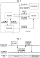
FIG. 4 shows an example of a communication sequence that is executed between an in-vehicle device and the terminal. - A vehicle control system of the invention performs control such that, in a case where vibration of a terminal is not detected for a predetermined time using a vibration detection unit that detects vibration of the terminal, an operation mode of the terminal is switched. With the above, in a case where the presence or absence of vibration of the terminal is repeatedly detected in a period shorter than the predetermined time, it is possible to further suppress frequent switching of the operation mode of the terminal due to carelessness, and to achieve electric power saving.
-
FIG. 1 is a diagram illustrating the schematic configuration of a vehicle control system 1 according to an embodiment of the invention. InFIG. 1 , the vehicle control system 1 includes an in-vehicle device 10 that is provided in a vehicle, and aterminal 20 that can be carried with a user or the like. - The vehicle control system 1 performs encryption collation processing through a predetermined communication sequence between the in-
vehicle device 10 and theterminal 20 to allow the in-vehicle device 10 to authenticate theterminal 20 and to realize predetermined vehicle control (unlocking or locking of a vehicle door, start of an engine, or the like), or switching of a predetermined operation mode in theterminal 20. - The
terminal 20 is a concept including an electronic key dedicated to a vehicle operation, and an electronic apparatus, such as a smartphone, in which predetermined key information downloaded from a server or the like is set. In the following embodiment, the vehicle control system 1 will be described in connection with an example where an electronic key is used as theterminal 20. - In
FIG. 1 , the in-vehicle device 10 includes a transmission andreception unit 11, a getting-in and getting-offdetermination unit 12, and amode switching controller 13. - The transmission and
reception unit 11 can perform communication with a transmission andreception unit 21 of an electronic key 20 described below. Specifically, the transmission andreception unit 11 can transmit an instruction command (hereinafter, referred to a "mode switching command") for switching an operation mode of the electronic key 20 generated in themode switching controller 13 to the electronic key 20 through a transmission antenna (not shown). The transmission andreception unit 11 can receive a prescribed switch operation (SW operation) input to the electronic key 20 from the electronic key 20 through a reception antenna (not shown). - The getting-in and getting-off
determination unit 12 can perform getting-in determination indicating that an occupant gets in the vehicle and getting-off determination indicating that an occupant gets off the vehicle. The getting-in determination may be performed, for example, by detecting change from a state in which any door of the vehicle is opened to a state in which all doors of the vehicle are closed. The getting-in determination may be performed, for example, by detecting change of a seating sensor, a camera sensor, or the like provided inside a vehicle cabin. The getting-in determination may be performed, for example, by detecting change of a suspension of the vehicle. The getting-off determination may be performed, for example, by detecting change from a state in which all doors of the vehicle are closed to a state in which any door of the vehicle is opened. The getting-off determination may be performed, for example, by detecting change of the seating sensor, a camera sensor, or the suspension. - The
mode switching controller 13 generates the mode switching command based on the getting-in determination or the getting-off determination performed in the getting-in and getting-offdetermination unit 12. Themode switching controller 13 performs control such that the transmission andreception unit 11 transmits the generated mode switching command. - The whole or a part of the in-
vehicle device 10 described above can be constituted as an electronic control unit (ECU) typically including a central processing unit (CPU), a memory, an input/output interface, and the like. In the electronic control unit, the CPU reads and executes a predetermined program stored in the memory, whereby a predetermined function is realized. - In
FIG. 1 , theelectronic key 20 includes a transmission andreception unit 21, avibration detection unit 22, and amode switching controller 23. - The transmission and
reception unit 21 can perform communication with the transmission andreception unit 11 of the in-vehicle device 10. Specifically, the transmission andreception unit 21 can receive the mode switching command for switching the operation mode of the electronic key 20 from the in-vehicle device 10 through a reception antenna (not shown). The transmission andreception unit 21 can transmit information of a prescribed switch operation (SW operation) input to the electronic key 20 to the in-vehicle device 10 through a transmission antenna (not shown). - The
vibration detection unit 22 can detect whether or not the electronic key 20 vibrates. For the vibration detection, for example, an acceleration sensor can be used. A result of the vibration detection is output to themode switching controller 23. - The
mode switching controller 23 can switch and set the operation mode of the electronic key 20 according to the result of the vibration detection output from thevibration detection unit 22 or the mode switching command received by the transmission andreception unit 21. The electronic key 20 according to the embodiment has a plurality of modes as a switchable operation mode. The modes will be described below. -
FIG. 2 is a state transition diagram of the electronic key 20 in the vehicle control system 1 according to the embodiment of the invention. As shown inFIG. 2 , in the vehicle control system 1, theelectronic key 20 has a first mode, a second mode, a third mode, and a fourth mode as a switchable operation mode. - The first mode is a mode that is set based on getting-off determination in the in-
vehicle device 10, and is, for example, an extra-vehicle cabin mode. The first mode can be set based on a first signal that is transmitted from the in-vehicle device 10 in a case where the getting-off determination is performed in the in-vehicle device 10. In the first mode, communication between theelectronic key 20 and the in-vehicle device 10 is not restricted. - In the first mode, in a case where vibration of the
electronic key 20 is not detected by thevibration detection unit 22 for a predetermined time (hereinafter, referred to as a "first time N1"), the operation mode of theelectronic key 20 is switched from the first mode to the third mode, and state transition is made. In the first mode, in a case where the getting-in determination is performed in the in-vehicle device 10, the operation mode of theelectronic key 20 is switched from the first mode to the third mode, and state transition is made. - The second mode is a mode that is set based on getting-in determination in the in-
vehicle device 10, and is, for example, an intra-vehicle cabin mode. The second mode can be set based on a second signal that is transmitted from the in-vehicle device 10 in a case where the getting-in determination is performed in the in-vehicle device 10. As in the first mode, in the second mode, communication between theelectronic key 20 and the in-vehicle device 10 is not restricted. - In the second mode, in a case where vibration of the
electronic key 20 is not detected by thevibration detection unit 22 for a predetermined time (hereinafter, referred to as a "second time N2") or in a case where the getting-off determination is performed in the in-vehicle device 10, the operation mode of theelectronic key 20 is switched from the second mode to the first mode, and state transition is made. In the former case, in the second mode, in a case where vibration of theelectronic key 20 is not detected by thevibration detection unit 22 for the first time N1 besides the second time N2, the operation mode of theelectronic key 20 is switched from the second mode to the third mode. Accordingly, in the second mode, in a case where vibration of theelectronic key 20 is not detected by thevibration detection unit 22 for a time (= the first time N1 + the second time N2) longer than the first time N1, the operation mode of theelectronic key 20 is switched from the second mode to the third mode. - The third mode is a mode that is set based on the result of the vibration detection in the
vibration detection unit 22. In the third mode, communication between theelectronic key 20 and the in-vehicle device 10 is restricted. A content of restriction in the third mode may be disabling reception of an electric wave signal from the in-vehicle device 10, disabling a response to an electric wave signal received from the in-vehicle device 10, or a combination thereof. With the restriction of the third mode, since it is possible to reduce electric power of the electronic key 20 that is consumed for communication with the in-vehicle device 10, the third mode may also be referred to as an electric power reduction mode or an electric power saving mode. - In the third mode, in a case where vibration is detected by the
vibration detection unit 22 or in a case where a prescribed switch operation (SW operation) is performed, the operation mode of theelectronic key 20 is switched from the third mode to the first mode, and state transition is made. The prescribed switch operation is, for example, depression of a door unlock button provided in theelectronic key 20, or the like. - The fourth mode is a mode where communication between the
electronic key 20 and the in-vehicle device 10 is restricted. A content of restriction in the fourth mode may be the same as in the third mode, or further restriction may be put compared to the third mode (for example, stopping of the operation of thevibration detection unit 22, or the like). - Switching to the fourth mode is performed in a case where a prescribed special operation is performed in the first mode or the second mode. The prescribed special operation is, for example, an operation of a dedicated button provided in the
electronic key 20, or the like. - In the fourth mode, in a case where a prescribed switch operation (SW operation) is performed, the operation mode of the
electronic key 20 is switched from the fourth mode to the first mode or the second mode, and state transition is made. The mode to be switched may be prescribed or may be determined according to an electric wave signal transmitted from the vehicle. The prescribed switch operation is, for example, depression of a door unlock button provided in theelectronic key 20, or the like. - In the operation mode of the electronic key 20 described above, for example, in a scene where the first mode assuming that the
electronic key 20 is outside the vehicle cabin is set, the first time N1 is set to be relatively short, and it is possible to quickly switch the operation mode of the electronic key 20 from the first mode to the third mode. Accordingly, electric power saving of theelectronic key 20 is achieved. Since communication with the in-vehicle device 10 is restricted in the third mode, it is possible to reduce erroneous transmission of theelectronic key 20 due to exogenous noise, and to expect an effect of further improving security of the vehicle. - For example, in a scene where the second mode assuming that the
electronic key 20 is inside the vehicle cabin is set, the second time N2 is set to be relatively long, for example, longer than the first time N1, and it is possible to further delay the time until the operation mode of theelectronic key 20 is switched from the second mode to the third mode. For this reason, it is possible to further suppress switching of the operation mode of the electronic key 20 to the third mode due to carelessness at the time of vehicle traveling. - Determination about whether the
electronic key 20 is outside the vehicle cabin or inside the vehicle cabin can be performed with an electric wave signal that is transmitted from the in-vehicle device 10 outward of the vehicle cabin or inward of the vehicle cabin, other than determining the opening and closing of the vehicle doors. -
FIG. 3 is a state transition diagram of the electronic key 20 according to a modification example in the vehicle control system 1 according to the embodiment. In comparison of the state transition diagram shown inFIG. 3 with the state transition diagram shown inFIG. 2 , while the switchable operation modes of the electronic key 20 are the same, a condition for switching from the second mode to the first mode and the third mode is different as follows. - In the second mode, in a case where vibration of the
electronic key 20 is not detected by thevibration detection unit 22 for a predetermined time (hereinafter, referred to as a "third time N3"), the operation mode of theelectronic key 20 is switched directly from the second mode to the third mode, and state transition is made. In the second mode, in a case where the getting-off determination is performed in the in-vehicle device 10, the operation mode of theelectronic key 20 is switched from the second mode to the first mode, and state transition is made. The third time N3 may be a time longer than the first time N1, or may be a time (= N1 + N2) obtained by adding the first time N1 and the second time N2. - According to the modification example, it is possible to achieve electric power saving of the
electronic key 20, to further reduce erroneous transmission of theelectronic key 20 due to exogenous noise, and to further improve security of the vehicle. Furthermore, it is possible to further suppress switching of the operation mode of the electronic key 20 to the first mode due to carelessness at the time of vehicle traveling. - In the embodiment, an example where the electronic key 20 can switch the operation mode according to the mode switching command transmitted from the in-
vehicle device 10 has been described. Here, a switching method example of the operation mode of the electronic key 20 with further improved security will be described. - In a specific example of mode switching, in a case where predetermined communication using a signal that is generated based on a predetermined value X updated each time the first signal is received is successful between the
electronic key 20 and the in-vehicle device 10, theelectronic key 20 performs switching processing of the operation mode according to the mode switching command. The predetermined communication can be performed, for example, as follows referring toFIG. 4 . - In a case where there is a need to switch the operation mode of the electronic key 20 with determination in the getting-in and getting-off
determination unit 12, the in-vehicle device 10 transmits the first signal including a mode switching request to theelectronic key 20. In a case where the first signal is received from the in-vehicle device 10, theelectronic key 20 generates the second signal based on the predetermined value X and transmits the second signal to the in-vehicle device 10. In a case where the second signal is received from theelectronic key 20, the in-vehicle device 10 generates the mode switching command (third signal) based on the second signal and transmits the mode switching command (third signal) to the in-vehicle device 10. In a case where the mode switching command (third signal) is received from the in-vehicle device 10, theelectronic key 20 determines whether or not the command is generated based on the predetermined value X. In a case where determination is made that the mode switching command is generated based on the predetermined value X, the electronic key 20 switches the operation mode of theelectronic key 20. - For the predetermined value X, for example, a random number, reception strength (received signal strength indicator (RSSI)) of the first signal in the
electronic key 20, a communication frequency between theelectronic key 20 and the in-vehicle device 10, and the like can be used. For example, in a case where theelectronic key 20 is provided with random number generation means, a random number that is generated each time theelectronic key 20 receives the first signal can be acquired as the predetermined value X. For example, a Burst signal for RSSI measurement is included in the first signal in advance, and reception strength of the Burst signal that is measured each time theelectronic key 20 receives the first signal can be acquired as the predetermined value X. For example, theelectronic key 20 is provided with a counter, and a counter value that is integrated each time theelectronic key 20 receives the first signal can be acquired as the predetermined value X. - As described above, with the vehicle control system 1 according to the embodiment of the invention, in a case where vibration of the
electronic key 20 is not detected for the first time N1 using thevibration detection unit 22 that detects vibration of theelectronic key 20, control is performed such that the operation mode of theelectronic key 20 is switched from the second mode to the first mode, and in a case where vibration of theelectronic key 20 is not detected in thevibration detection unit 22 for "the first time N1 + the second time N2" or "the third time N3" longer than the first time N1, control is performed such that the operation mode of theelectronic key 20 is switched from the third mode to the first mode. - With the above-described control, even though vibration of the
electronic key 20 is not detected, the operation mode of theelectronic key 20 is not switched from the second mode or the third mode to the first mode instantly. Accordingly, it is possible to further suppress frequent switching of the operation mode of theelectronic key 20 due to carelessness in a case where the presence or absence of vibration of theelectronic key 20 is repeatedly detected in a period shorter than the first time N1. - The time until the operation mode of the
electronic key 20 is switched to the first mode in a case where vibration of theelectronic key 20 is not detected is set to the relatively short first time N1 in the second mode, and to be the relatively long "first time N1 + second time N2" or "third time N3" in the third mode. With the above, for example, in the second mode that is the extra-vehicle cabin mode, it is possible to achieve separation and division of control, such as quickly performing mode switching to achieve electric power saving of theelectronic key 20 and to further reduce erroneous transmission due to exogenous noise, and in the third mode that is the intra-vehicle cabin mode, preventing unneeded switching of the operation mode of theelectronic key 20. - The invention is usable in a vehicle control system that an in-vehicle device and an electronic key perform communication to control a vehicle, or the like. In addition, the invention is not limited to the above-described embodiment, and various alterations may be made without departing from the spirit and scope of the invention described in the claims.
Claims (13)
- A terminal (20) that performs communication with an in-vehicle device (10) to control a vehicle, the terminal (20) comprising:a controller configured to switch and set a plurality of operation modes of the terminal; anda vibration detection unit (22) configured to detect vibration of the terminal (20), wherein:the operation modes of the terminal includea first mode,a second mode different from the first mode, anda third mode where communication with the in-vehicle device (10) is more restricted than in the first mode and the second mode; andthe controller is configured towhen the first mode is executed, in a case where vibration is not detected in the vibration detection unit (22) for a predetermined time, switch the operation mode of the terminal (20) to the third mode, andwhen the second mode is executed, in a case where vibration is not detected in the vibration detection unit (22) for a time longer than the predetermined time, switch the operation mode of the terminal (20) to the third mode.
- The terminal (20) according to claim 1, wherein the controller is configured to set the operation mode of the terminal (20) to the first mode based on getting-off determination in the in-vehicle device (10).
- The terminal (20) according to claim 1 or 2, wherein the controller is configured to set the operation mode of the terminal (20) to the second mode based on getting-in determination in the in-vehicle device (10).
- The terminal (20) according to claim 3, wherein the getting-in determination is performed in a case where all doors of the vehicle are closed.
- The terminal (20) according to claim 2, wherein the getting-off determination is performed in a case where at least one door of the vehicle is opened.
- The terminal (20) according to any one of claims 1 to 5, wherein the controller is configured to, when the third mode is executed, in a case where a first input operation on the terminal (20) is detected or in a case where vibration is detected in the vibration detection unit (22), switch the operation mode of the terminal (20) to the first mode.
- The terminal (20) according to any one of claims 1 to 6, wherein the controller is configured to, in a case where predetermined communication using a signal that is generated based on a random number generated by the terminal (20) is successful between the terminal (20) and the in-vehicle device (10), perform switching of the operation mode of the terminal (20).
- The terminal (20) according to any one of claims 1 to 6, wherein the controller is configured to, in a case where predetermined communication using a signal that is generated based on reception strength of a signal transmitted from the in-vehicle device (10) is successful between the terminal (20) and the in-vehicle device (10), perform switching of the operation mode of the terminal (20).
- The terminal (20) according to any one of claims 1 to 6, wherein the controller is configured to, in a case where predetermined communication using a signal that is generated based on the number of communications between the terminal (20) and the in-vehicle device (10) is successful between the terminal (20) and the in-vehicle device (10), perform switching of the operation mode of the terminal (20).
- The terminal (20) according to any one of claims 1 to 9, wherein the vibration detection unit (22) is configured to detect vibration using an acceleration sensor.
- The terminal (20) according to any one of claims 1 to 10, wherein the controller is configured towhen the first mode or the second mode is executed, in a case where a second input operation on the terminal (20) is detected, switch the operation mode of the terminal (20) to a fourth mode where communication with the in-vehicle device (10) is restricted, andwhen the fourth mode is executed, in a case where a third input operation on the terminal (20) is detected, switch the operation mode of the terminal (20) to the first mode and the second mode.
- A vehicle control method that a terminal (20) configured to perform communication with an in-vehicle device (10) to control a vehicle executes, the terminal (20) having operation modes of a first mode, a second mode different from the first mode, and a third mode where communication with the in-vehicle device (10) is more restricted than in the first mode and the second mode, the vehicle control method comprising:detecting vibration of the terminal (20);when the first mode is executed, in a case where vibration is not detected in the detecting of the vibration for a predetermined time, switching the operation mode of the terminal (20) to the third mode; andwhen the second mode is executed, in a case where vibration is not detected in the detecting of the vibration for a time longer than the predetermined time, switching the operation mode of the terminal (20) to the third mode.
- A vehicle control system (1) comprising:an in-vehicle device (10); anda terminal (20) performing communication with the in-vehicle device (10) to control a vehicle, the terminal includinga controller configured to switch and set a first mode that is set based on a first signal transmitted from the in-vehicle device (10), a second mode that is set based on a second signal transmitted from the in-vehicle device (10), and a third mode where communication with the in-vehicle device (10) is more restricted than in the first mode and the second mode,a vibration detection unit (22) configured to detect vibration of the terminal (20), anda transmission unit configured to receive getting-in determination and getting-off determination from the in-vehicle device (10), wherein:the controller is configured towhen the first mode is executed, in a case where vibration is not detected in the vibration detection unit (22) for a predetermined time, switch an operation mode of the terminal (20) to the third mode, andwhen the second mode is executed, in a case where vibration is not detected in the vibration detection unit (22) for a time longer than the predetermined time, switch the operation mode of the terminal (20) to the third mode.
Applications Claiming Priority (1)
| Application Number | Priority Date | Filing Date | Title |
|---|---|---|---|
| JP2017186792A JP6812939B2 (en) | 2017-09-27 | 2017-09-27 | Terminals, vehicle control systems, and vehicle control methods |
Publications (2)
| Publication Number | Publication Date |
|---|---|
| EP3462421A1 true EP3462421A1 (en) | 2019-04-03 |
| EP3462421B1 EP3462421B1 (en) | 2021-10-20 |
Family
ID=63404962
Family Applications (1)
| Application Number | Title | Priority Date | Filing Date |
|---|---|---|---|
| EP18188302.6A Active EP3462421B1 (en) | 2017-09-27 | 2018-08-09 | Electronic vehicle key with power saving mode |
Country Status (6)
| Country | Link |
|---|---|
| US (1) | US10988108B2 (en) |
| EP (1) | EP3462421B1 (en) |
| JP (1) | JP6812939B2 (en) |
| KR (1) | KR102144729B1 (en) |
| CN (2) | CN113561938B (en) |
| RU (1) | RU2699748C1 (en) |
Families Citing this family (8)
| Publication number | Priority date | Publication date | Assignee | Title |
|---|---|---|---|---|
| CN112144966A (en) * | 2019-08-01 | 2020-12-29 | 安波福电子(苏州)有限公司 | Automobile intelligent key capable of prolonging service life of battery |
| JP2021098937A (en) * | 2019-12-20 | 2021-07-01 | セイコーエプソン株式会社 | Circuit device, electronic device, communication system, and vehicular electronic key system |
| JP7331782B2 (en) * | 2020-05-29 | 2023-08-23 | トヨタ自動車株式会社 | Communication device, system, vehicle, and communication method |
| WO2022113357A1 (en) * | 2020-11-30 | 2022-06-02 | パイオニア株式会社 | Communication control terminal, communication control method, and communication control program |
| JP7627842B2 (en) * | 2021-06-25 | 2025-02-07 | パナソニックIpマネジメント株式会社 | CONTROL SYSTEM, CONTROL METHOD, AND PROGRAM |
| CN113347711B (en) * | 2021-08-06 | 2021-11-09 | 杭州控客信息技术有限公司 | Terminal self-adaption method and system in personnel positioning system |
| JP7829455B2 (en) | 2022-09-26 | 2026-03-13 | 株式会社東海理化電機製作所 | Control device, control method, and program |
| CN117912143A (en) * | 2024-02-04 | 2024-04-19 | 小米汽车科技有限公司 | Vehicle key processing method and device, vehicle key and storage medium |
Citations (2)
| Publication number | Priority date | Publication date | Assignee | Title |
|---|---|---|---|---|
| JP2012227586A (en) | 2011-04-15 | 2012-11-15 | Nippon Soken Inc | Portable radio communication apparatus |
| US20170197586A1 (en) * | 2014-09-12 | 2017-07-13 | Kabushiki Kaisha Tokai Rika Denki Seisakusho | Portable device |
Family Cites Families (42)
| Publication number | Priority date | Publication date | Assignee | Title |
|---|---|---|---|---|
| DE19937915A1 (en) | 1998-09-02 | 2000-03-09 | Mannesmann Vdo Ag | Electronic key for remotely unlocking a motor vehicle has a power supply that can be interrupted to prevent transmission of an identification signal |
| JP4649703B2 (en) * | 1999-08-27 | 2011-03-16 | トヨタ自動車株式会社 | Automatic moving body locking device |
| US6337626B1 (en) * | 2000-07-25 | 2002-01-08 | Dennis Huang | User recognition system |
| FR2834344A1 (en) | 2001-12-28 | 2003-07-04 | Siemens Vdo Automotive | METHOD FOR DETECTING A BADGE WITHIN A VEHICLE EQUIPPED WITH A HANDS-FREE SYSTEM |
| JP3988618B2 (en) * | 2002-10-30 | 2007-10-10 | 株式会社デンソー | Vehicle remote control device |
| JP2005290900A (en) * | 2004-04-02 | 2005-10-20 | Auto Network Gijutsu Kenkyusho:Kk | Keyless entry system |
| US7292137B2 (en) * | 2005-05-13 | 2007-11-06 | Lear Corporation | Energy efficient passive entry system |
| JP4613788B2 (en) * | 2005-10-17 | 2011-01-19 | トヨタ自動車株式会社 | Vehicle door unlock control device |
| JP5205897B2 (en) | 2007-09-27 | 2013-06-05 | 株式会社Jvcケンウッド | Portable content processing apparatus, control method, and program |
| US8193915B2 (en) * | 2008-03-06 | 2012-06-05 | GM Global Technology Operations LLC | Multiple transceiver synchronous communication system |
| US20090243795A1 (en) * | 2008-03-27 | 2009-10-01 | Lear Corporation | Automotive passive entry system and method of operating same |
| KR100958081B1 (en) * | 2008-04-22 | 2010-05-14 | 동아대학교 산학협력단 | Passive entry system and method of performing its function |
| JP2010128610A (en) | 2008-11-25 | 2010-06-10 | Fujitsu Ten Ltd | Drive recorder |
| JP5173891B2 (en) * | 2009-03-02 | 2013-04-03 | 株式会社東海理化電機製作所 | Secret key registration system and secret key registration method |
| US8547253B2 (en) * | 2009-09-04 | 2013-10-01 | GM Global Technology Operations LLC | Method of determining vehicle location from key fob |
| US8659414B1 (en) * | 2010-12-22 | 2014-02-25 | Chad Schuk | Wireless object-proximity monitoring and alarm system |
| DE102011013605A1 (en) * | 2011-03-10 | 2012-09-13 | Volkswagen Aktiengesellschaft | Mobile transmission device of an access system of a vehicle |
| KR101927217B1 (en) * | 2011-05-03 | 2018-12-10 | 엘지이노텍 주식회사 | Method for controlling smartkey system for door lock |
| WO2013044221A2 (en) * | 2011-09-23 | 2013-03-28 | Honda Motor Co., Ltd | Selective current reduction enabled with electrically deactivated key fob |
| EP2784249B1 (en) * | 2011-11-25 | 2018-02-14 | Mitsubishi Electric Corporation | Mobile device |
| JP5803724B2 (en) * | 2012-02-15 | 2015-11-04 | トヨタ自動車株式会社 | Authentication system and authentication device |
| CN104302517A (en) * | 2012-05-18 | 2015-01-21 | 丰田自动车株式会社 | Vehicle information display device |
| US20140114503A1 (en) * | 2012-10-24 | 2014-04-24 | Lear Corporation | Remote Function Fob for a Vehicle Passive Entry Passive Start System and Method for Operating Same |
| JP5977146B2 (en) | 2012-11-05 | 2016-08-24 | 株式会社東海理化電機製作所 | Electronic key system |
| JP5704180B2 (en) * | 2013-01-31 | 2015-04-22 | トヨタ自動車株式会社 | Electronic key terminal power consumption suppression system and electronic key terminal power consumption suppression method |
| JP6026910B2 (en) | 2013-02-08 | 2016-11-16 | 学校法人 関西大学 | Wireless device and wireless communication system including the same |
| US20140335816A1 (en) * | 2013-05-13 | 2014-11-13 | Jesse Wayne Long | Key fob communicator |
| US9086879B2 (en) * | 2013-07-26 | 2015-07-21 | GM Global Technology Operations LLC | Methods and apparatus for optimizing battery life in a remote device |
| DE102013017523A1 (en) * | 2013-10-23 | 2015-04-23 | Airbus Ds Gmbh | ELECTRONICALLY CONTROLLED LOCKING SYSTEM AND ELECTRONIC KEY TO CONTROL THE LOCKING SYSTEM |
| US9646436B1 (en) * | 2013-12-31 | 2017-05-09 | Huf North America Automotive Parts Manufacturing, Corp. | Gesture controls for remote vehicle access systems |
| KR20150130818A (en) * | 2014-05-14 | 2015-11-24 | 엘지전자 주식회사 | Mobile terminal and method for controlling the same |
| CN104709231B (en) * | 2015-01-21 | 2017-05-10 | 扬州阿尔斯特科技有限公司 | Intelligent key system based on automobile control system and working method thereof |
| JP6520283B2 (en) * | 2015-03-25 | 2019-05-29 | 株式会社デンソー | User identification system, portable device for vehicle |
| CN105128816A (en) * | 2015-09-14 | 2015-12-09 | 广东顺德车联管家科技有限公司 | Vehicle control method and vehicle-mounted terminal |
| KR101744727B1 (en) * | 2015-12-07 | 2017-06-08 | 현대자동차주식회사 | A smart key, a method for controlliong the smart key and a vehicle including the smart key |
| US10054607B2 (en) * | 2016-05-12 | 2018-08-21 | Google Llc | Using accelerometer to self-test piezoelectric component in a portable device |
| JP2018028182A (en) * | 2016-08-15 | 2018-02-22 | 株式会社東海理化電機製作所 | Portable machine and electronic key system |
| CN206264989U (en) * | 2016-12-21 | 2017-06-20 | 成都亿佰特电子科技有限公司 | A kind of automobile PKE systems |
| JP6705373B2 (en) * | 2016-12-27 | 2020-06-03 | トヨタ自動車株式会社 | Automatic driving system |
| DE102017201087B4 (en) * | 2017-01-24 | 2019-08-14 | Volkswagen Aktiengesellschaft | Device, key remote and method for controlling operating conditions of a key module |
| CN107097753B (en) * | 2017-05-02 | 2020-01-31 | 大陆汽车电子(长春)有限公司 | Vehicle smart key system and method for verifying vehicle smart key |
| JP6866818B2 (en) * | 2017-09-27 | 2021-04-28 | トヨタ自動車株式会社 | Terminals, vehicle control systems, and vehicle control methods |
-
2017
- 2017-09-27 JP JP2017186792A patent/JP6812939B2/en active Active
-
2018
- 2018-08-03 US US16/054,433 patent/US10988108B2/en active Active
- 2018-08-07 RU RU2018128794A patent/RU2699748C1/en active
- 2018-08-09 EP EP18188302.6A patent/EP3462421B1/en active Active
- 2018-08-21 KR KR1020180097301A patent/KR102144729B1/en active Active
- 2018-09-04 CN CN202110968683.XA patent/CN113561938B/en active Active
- 2018-09-04 CN CN201811027399.7A patent/CN109552248B/en active Active
Patent Citations (2)
| Publication number | Priority date | Publication date | Assignee | Title |
|---|---|---|---|---|
| JP2012227586A (en) | 2011-04-15 | 2012-11-15 | Nippon Soken Inc | Portable radio communication apparatus |
| US20170197586A1 (en) * | 2014-09-12 | 2017-07-13 | Kabushiki Kaisha Tokai Rika Denki Seisakusho | Portable device |
Also Published As
| Publication number | Publication date |
|---|---|
| CN113561938B (en) | 2023-12-22 |
| EP3462421B1 (en) | 2021-10-20 |
| JP6812939B2 (en) | 2021-01-13 |
| KR102144729B1 (en) | 2020-08-14 |
| CN109552248A (en) | 2019-04-02 |
| CN109552248B (en) | 2021-09-10 |
| BR102018069745A2 (en) | 2019-04-16 |
| CN113561938A (en) | 2021-10-29 |
| JP2019059405A (en) | 2019-04-18 |
| RU2699748C1 (en) | 2019-09-09 |
| KR20190036464A (en) | 2019-04-04 |
| US10988108B2 (en) | 2021-04-27 |
| US20190092278A1 (en) | 2019-03-28 |
Similar Documents
| Publication | Publication Date | Title |
|---|---|---|
| EP3462421B1 (en) | Electronic vehicle key with power saving mode | |
| EP3461699B1 (en) | Terminal, vehicle control system, and vehicle control method | |
| WO2015145497A1 (en) | Vehicular near field communication system, portable device, and on-board instrument | |
| JP6760206B2 (en) | In-vehicle authentication device, portable device authentication method | |
| JP2019156283A (en) | Walking detection device and system | |
| JP2020090159A (en) | In-vehicle device, electronic key system and communication method | |
| US10632967B2 (en) | Vehicle alarm system | |
| KR102192457B1 (en) | In-vehicle communication device and communication method | |
| WO2021192598A1 (en) | Distance estimation device | |
| US20240144758A1 (en) | Vehicle control device, vehicle, vehicle control method and recording medium on which a program is recorded | |
| JP2008169663A (en) | Portable device and vehicle remote control system using the same | |
| BR102018069745B1 (en) | TERMINAL, VEHICLE CONTROL SYSTEM AND VEHICLE CONTROL METHOD | |
| BR102018016578B1 (en) | TERMINAL, VEHICLE CONTROL SYSTEM, AND VEHICLE CONTROL METHOD |
Legal Events
| Date | Code | Title | Description |
|---|---|---|---|
| PUAI | Public reference made under article 153(3) epc to a published international application that has entered the european phase |
Free format text: ORIGINAL CODE: 0009012 |
|
| STAA | Information on the status of an ep patent application or granted ep patent |
Free format text: STATUS: REQUEST FOR EXAMINATION WAS MADE |
|
| 17P | Request for examination filed |
Effective date: 20180809 |
|
| AK | Designated contracting states |
Kind code of ref document: A1 Designated state(s): AL AT BE BG CH CY CZ DE DK EE ES FI FR GB GR HR HU IE IS IT LI LT LU LV MC MK MT NL NO PL PT RO RS SE SI SK SM TR |
|
| AX | Request for extension of the european patent |
Extension state: BA ME |
|
| STAA | Information on the status of an ep patent application or granted ep patent |
Free format text: STATUS: EXAMINATION IS IN PROGRESS |
|
| 17Q | First examination report despatched |
Effective date: 20200709 |
|
| GRAP | Despatch of communication of intention to grant a patent |
Free format text: ORIGINAL CODE: EPIDOSNIGR1 |
|
| STAA | Information on the status of an ep patent application or granted ep patent |
Free format text: STATUS: GRANT OF PATENT IS INTENDED |
|
| INTG | Intention to grant announced |
Effective date: 20210414 |
|
| RIN1 | Information on inventor provided before grant (corrected) |
Inventor name: KAMEYAMA, YUUTO Inventor name: KOMEYA, MASASHI Inventor name: NISHIYAMA, SHIGEKI Inventor name: YOSHIHARA, TORU Inventor name: FUNAYAMA, TOMOYUKI Inventor name: OKADA, HIROKI |
|
| GRAJ | Information related to disapproval of communication of intention to grant by the applicant or resumption of examination proceedings by the epo deleted |
Free format text: ORIGINAL CODE: EPIDOSDIGR1 |
|
| STAA | Information on the status of an ep patent application or granted ep patent |
Free format text: STATUS: EXAMINATION IS IN PROGRESS |
|
| GRAP | Despatch of communication of intention to grant a patent |
Free format text: ORIGINAL CODE: EPIDOSNIGR1 |
|
| STAA | Information on the status of an ep patent application or granted ep patent |
Free format text: STATUS: GRANT OF PATENT IS INTENDED |
|
| INTC | Intention to grant announced (deleted) | ||
| INTG | Intention to grant announced |
Effective date: 20210802 |
|
| GRAS | Grant fee paid |
Free format text: ORIGINAL CODE: EPIDOSNIGR3 |
|
| GRAA | (expected) grant |
Free format text: ORIGINAL CODE: 0009210 |
|
| STAA | Information on the status of an ep patent application or granted ep patent |
Free format text: STATUS: THE PATENT HAS BEEN GRANTED |
|
| AK | Designated contracting states |
Kind code of ref document: B1 Designated state(s): AL AT BE BG CH CY CZ DE DK EE ES FI FR GB GR HR HU IE IS IT LI LT LU LV MC MK MT NL NO PL PT RO RS SE SI SK SM TR |
|
| REG | Reference to a national code |
Ref country code: GB Ref legal event code: FG4D |
|
| REG | Reference to a national code |
Ref country code: CH Ref legal event code: EP |
|
| REG | Reference to a national code |
Ref country code: DE Ref legal event code: R096 Ref document number: 602018025220 Country of ref document: DE |
|
| REG | Reference to a national code |
Ref country code: IE Ref legal event code: FG4D |
|
| REG | Reference to a national code |
Ref country code: AT Ref legal event code: REF Ref document number: 1440563 Country of ref document: AT Kind code of ref document: T Effective date: 20211115 |
|
| REG | Reference to a national code |
Ref country code: LT Ref legal event code: MG9D |
|
| REG | Reference to a national code |
Ref country code: NL Ref legal event code: MP Effective date: 20211020 |
|
| REG | Reference to a national code |
Ref country code: AT Ref legal event code: MK05 Ref document number: 1440563 Country of ref document: AT Kind code of ref document: T Effective date: 20211020 |
|
| PG25 | Lapsed in a contracting state [announced via postgrant information from national office to epo] |
Ref country code: RS Free format text: LAPSE BECAUSE OF FAILURE TO SUBMIT A TRANSLATION OF THE DESCRIPTION OR TO PAY THE FEE WITHIN THE PRESCRIBED TIME-LIMIT Effective date: 20211020 Ref country code: LT Free format text: LAPSE BECAUSE OF FAILURE TO SUBMIT A TRANSLATION OF THE DESCRIPTION OR TO PAY THE FEE WITHIN THE PRESCRIBED TIME-LIMIT Effective date: 20211020 Ref country code: FI Free format text: LAPSE BECAUSE OF FAILURE TO SUBMIT A TRANSLATION OF THE DESCRIPTION OR TO PAY THE FEE WITHIN THE PRESCRIBED TIME-LIMIT Effective date: 20211020 Ref country code: BG Free format text: LAPSE BECAUSE OF FAILURE TO SUBMIT A TRANSLATION OF THE DESCRIPTION OR TO PAY THE FEE WITHIN THE PRESCRIBED TIME-LIMIT Effective date: 20220120 Ref country code: AT Free format text: LAPSE BECAUSE OF FAILURE TO SUBMIT A TRANSLATION OF THE DESCRIPTION OR TO PAY THE FEE WITHIN THE PRESCRIBED TIME-LIMIT Effective date: 20211020 |
|
| PG25 | Lapsed in a contracting state [announced via postgrant information from national office to epo] |
Ref country code: IS Free format text: LAPSE BECAUSE OF FAILURE TO SUBMIT A TRANSLATION OF THE DESCRIPTION OR TO PAY THE FEE WITHIN THE PRESCRIBED TIME-LIMIT Effective date: 20220220 Ref country code: SE Free format text: LAPSE BECAUSE OF FAILURE TO SUBMIT A TRANSLATION OF THE DESCRIPTION OR TO PAY THE FEE WITHIN THE PRESCRIBED TIME-LIMIT Effective date: 20211020 Ref country code: PT Free format text: LAPSE BECAUSE OF FAILURE TO SUBMIT A TRANSLATION OF THE DESCRIPTION OR TO PAY THE FEE WITHIN THE PRESCRIBED TIME-LIMIT Effective date: 20220221 Ref country code: PL Free format text: LAPSE BECAUSE OF FAILURE TO SUBMIT A TRANSLATION OF THE DESCRIPTION OR TO PAY THE FEE WITHIN THE PRESCRIBED TIME-LIMIT Effective date: 20211020 Ref country code: NO Free format text: LAPSE BECAUSE OF FAILURE TO SUBMIT A TRANSLATION OF THE DESCRIPTION OR TO PAY THE FEE WITHIN THE PRESCRIBED TIME-LIMIT Effective date: 20220120 Ref country code: NL Free format text: LAPSE BECAUSE OF FAILURE TO SUBMIT A TRANSLATION OF THE DESCRIPTION OR TO PAY THE FEE WITHIN THE PRESCRIBED TIME-LIMIT Effective date: 20211020 Ref country code: LV Free format text: LAPSE BECAUSE OF FAILURE TO SUBMIT A TRANSLATION OF THE DESCRIPTION OR TO PAY THE FEE WITHIN THE PRESCRIBED TIME-LIMIT Effective date: 20211020 Ref country code: HR Free format text: LAPSE BECAUSE OF FAILURE TO SUBMIT A TRANSLATION OF THE DESCRIPTION OR TO PAY THE FEE WITHIN THE PRESCRIBED TIME-LIMIT Effective date: 20211020 Ref country code: GR Free format text: LAPSE BECAUSE OF FAILURE TO SUBMIT A TRANSLATION OF THE DESCRIPTION OR TO PAY THE FEE WITHIN THE PRESCRIBED TIME-LIMIT Effective date: 20220121 Ref country code: ES Free format text: LAPSE BECAUSE OF FAILURE TO SUBMIT A TRANSLATION OF THE DESCRIPTION OR TO PAY THE FEE WITHIN THE PRESCRIBED TIME-LIMIT Effective date: 20211020 |
|
| REG | Reference to a national code |
Ref country code: DE Ref legal event code: R097 Ref document number: 602018025220 Country of ref document: DE |
|
| PG25 | Lapsed in a contracting state [announced via postgrant information from national office to epo] |
Ref country code: SM Free format text: LAPSE BECAUSE OF FAILURE TO SUBMIT A TRANSLATION OF THE DESCRIPTION OR TO PAY THE FEE WITHIN THE PRESCRIBED TIME-LIMIT Effective date: 20211020 Ref country code: SK Free format text: LAPSE BECAUSE OF FAILURE TO SUBMIT A TRANSLATION OF THE DESCRIPTION OR TO PAY THE FEE WITHIN THE PRESCRIBED TIME-LIMIT Effective date: 20211020 Ref country code: RO Free format text: LAPSE BECAUSE OF FAILURE TO SUBMIT A TRANSLATION OF THE DESCRIPTION OR TO PAY THE FEE WITHIN THE PRESCRIBED TIME-LIMIT Effective date: 20211020 Ref country code: EE Free format text: LAPSE BECAUSE OF FAILURE TO SUBMIT A TRANSLATION OF THE DESCRIPTION OR TO PAY THE FEE WITHIN THE PRESCRIBED TIME-LIMIT Effective date: 20211020 Ref country code: DK Free format text: LAPSE BECAUSE OF FAILURE TO SUBMIT A TRANSLATION OF THE DESCRIPTION OR TO PAY THE FEE WITHIN THE PRESCRIBED TIME-LIMIT Effective date: 20211020 Ref country code: CZ Free format text: LAPSE BECAUSE OF FAILURE TO SUBMIT A TRANSLATION OF THE DESCRIPTION OR TO PAY THE FEE WITHIN THE PRESCRIBED TIME-LIMIT Effective date: 20211020 |
|
| PLBE | No opposition filed within time limit |
Free format text: ORIGINAL CODE: 0009261 |
|
| STAA | Information on the status of an ep patent application or granted ep patent |
Free format text: STATUS: NO OPPOSITION FILED WITHIN TIME LIMIT |
|
| 26N | No opposition filed |
Effective date: 20220721 |
|
| PG25 | Lapsed in a contracting state [announced via postgrant information from national office to epo] |
Ref country code: AL Free format text: LAPSE BECAUSE OF FAILURE TO SUBMIT A TRANSLATION OF THE DESCRIPTION OR TO PAY THE FEE WITHIN THE PRESCRIBED TIME-LIMIT Effective date: 20211020 |
|
| PG25 | Lapsed in a contracting state [announced via postgrant information from national office to epo] |
Ref country code: SI Free format text: LAPSE BECAUSE OF FAILURE TO SUBMIT A TRANSLATION OF THE DESCRIPTION OR TO PAY THE FEE WITHIN THE PRESCRIBED TIME-LIMIT Effective date: 20211020 |
|
| PG25 | Lapsed in a contracting state [announced via postgrant information from national office to epo] |
Ref country code: MC Free format text: LAPSE BECAUSE OF FAILURE TO SUBMIT A TRANSLATION OF THE DESCRIPTION OR TO PAY THE FEE WITHIN THE PRESCRIBED TIME-LIMIT Effective date: 20211020 |
|
| REG | Reference to a national code |
Ref country code: CH Ref legal event code: PL |
|
| PG25 | Lapsed in a contracting state [announced via postgrant information from national office to epo] |
Ref country code: LU Free format text: LAPSE BECAUSE OF NON-PAYMENT OF DUE FEES Effective date: 20220809 Ref country code: LI Free format text: LAPSE BECAUSE OF NON-PAYMENT OF DUE FEES Effective date: 20220831 Ref country code: CH Free format text: LAPSE BECAUSE OF NON-PAYMENT OF DUE FEES Effective date: 20220831 |
|
| REG | Reference to a national code |
Ref country code: BE Ref legal event code: MM Effective date: 20220831 |
|
| PG25 | Lapsed in a contracting state [announced via postgrant information from national office to epo] |
Ref country code: IT Free format text: LAPSE BECAUSE OF FAILURE TO SUBMIT A TRANSLATION OF THE DESCRIPTION OR TO PAY THE FEE WITHIN THE PRESCRIBED TIME-LIMIT Effective date: 20211020 |
|
| P01 | Opt-out of the competence of the unified patent court (upc) registered |
Effective date: 20230427 |
|
| REG | Reference to a national code |
Ref country code: DE Ref legal event code: R084 Ref document number: 602018025220 Country of ref document: DE |
|
| PG25 | Lapsed in a contracting state [announced via postgrant information from national office to epo] |
Ref country code: IE Free format text: LAPSE BECAUSE OF NON-PAYMENT OF DUE FEES Effective date: 20220809 |
|
| REG | Reference to a national code |
Ref country code: GB Ref legal event code: 746 Effective date: 20230801 |
|
| PG25 | Lapsed in a contracting state [announced via postgrant information from national office to epo] |
Ref country code: BE Free format text: LAPSE BECAUSE OF NON-PAYMENT OF DUE FEES Effective date: 20220831 |
|
| PG25 | Lapsed in a contracting state [announced via postgrant information from national office to epo] |
Ref country code: HU Free format text: LAPSE BECAUSE OF FAILURE TO SUBMIT A TRANSLATION OF THE DESCRIPTION OR TO PAY THE FEE WITHIN THE PRESCRIBED TIME-LIMIT; INVALID AB INITIO Effective date: 20180809 |
|
| PG25 | Lapsed in a contracting state [announced via postgrant information from national office to epo] |
Ref country code: CY Free format text: LAPSE BECAUSE OF FAILURE TO SUBMIT A TRANSLATION OF THE DESCRIPTION OR TO PAY THE FEE WITHIN THE PRESCRIBED TIME-LIMIT Effective date: 20211020 |
|
| PG25 | Lapsed in a contracting state [announced via postgrant information from national office to epo] |
Ref country code: MK Free format text: LAPSE BECAUSE OF FAILURE TO SUBMIT A TRANSLATION OF THE DESCRIPTION OR TO PAY THE FEE WITHIN THE PRESCRIBED TIME-LIMIT Effective date: 20211020 |
|
| PG25 | Lapsed in a contracting state [announced via postgrant information from national office to epo] |
Ref country code: TR Free format text: LAPSE BECAUSE OF FAILURE TO SUBMIT A TRANSLATION OF THE DESCRIPTION OR TO PAY THE FEE WITHIN THE PRESCRIBED TIME-LIMIT Effective date: 20211020 |
|
| PG25 | Lapsed in a contracting state [announced via postgrant information from national office to epo] |
Ref country code: MT Free format text: LAPSE BECAUSE OF FAILURE TO SUBMIT A TRANSLATION OF THE DESCRIPTION OR TO PAY THE FEE WITHIN THE PRESCRIBED TIME-LIMIT Effective date: 20211020 |
|
| PGFP | Annual fee paid to national office [announced via postgrant information from national office to epo] |
Ref country code: GB Payment date: 20250619 Year of fee payment: 8 |
|
| PGFP | Annual fee paid to national office [announced via postgrant information from national office to epo] |
Ref country code: FR Payment date: 20250610 Year of fee payment: 8 |
|
| PGFP | Annual fee paid to national office [announced via postgrant information from national office to epo] |
Ref country code: DE Payment date: 20250618 Year of fee payment: 8 |