EP3462407A1 - Method and device for generating associated images and verifying them - Google Patents
Method and device for generating associated images and verifying them Download PDFInfo
- Publication number
- EP3462407A1 EP3462407A1 EP18186889.4A EP18186889A EP3462407A1 EP 3462407 A1 EP3462407 A1 EP 3462407A1 EP 18186889 A EP18186889 A EP 18186889A EP 3462407 A1 EP3462407 A1 EP 3462407A1
- Authority
- EP
- European Patent Office
- Prior art keywords
- image file
- image
- file
- random time
- time value
- Prior art date
- Legal status (The legal status is an assumption and is not a legal conclusion. Google has not performed a legal analysis and makes no representation as to the accuracy of the status listed.)
- Granted
Links
Images


Classifications
-
- G—PHYSICS
- G06—COMPUTING OR CALCULATING; COUNTING
- G06T—IMAGE DATA PROCESSING OR GENERATION, IN GENERAL
- G06T1/00—General purpose image data processing
- G06T1/0007—Image acquisition
-
- G—PHYSICS
- G06—COMPUTING OR CALCULATING; COUNTING
- G06F—ELECTRIC DIGITAL DATA PROCESSING
- G06F21/00—Security arrangements for protecting computers, components thereof, programs or data against unauthorised activity
- G06F21/10—Protecting distributed programs or content, e.g. vending or licensing of copyrighted material ; Digital rights management [DRM]
- G06F21/16—Program or content traceability, e.g. by watermarking
-
- G—PHYSICS
- G01—MEASURING; TESTING
- G01N—INVESTIGATING OR ANALYSING MATERIALS BY DETERMINING THEIR CHEMICAL OR PHYSICAL PROPERTIES
- G01N23/00—Investigating or analysing materials by the use of wave or particle radiation, e.g. X-rays or neutrons, not covered by groups G01N3/00 – G01N17/00, G01N21/00 or G01N22/00
- G01N23/02—Investigating or analysing materials by the use of wave or particle radiation, e.g. X-rays or neutrons, not covered by groups G01N3/00 – G01N17/00, G01N21/00 or G01N22/00 by transmitting the radiation through the material
- G01N23/04—Investigating or analysing materials by the use of wave or particle radiation, e.g. X-rays or neutrons, not covered by groups G01N3/00 – G01N17/00, G01N21/00 or G01N22/00 by transmitting the radiation through the material and forming images of the material
-
- G—PHYSICS
- G01—MEASURING; TESTING
- G01V—GEOPHYSICS; GRAVITATIONAL MEASUREMENTS; DETECTING MASSES OR OBJECTS; TAGS
- G01V5/00—Prospecting or detecting by the use of ionising radiation, e.g. of natural or induced radioactivity
-
- G—PHYSICS
- G06—COMPUTING OR CALCULATING; COUNTING
- G06F—ELECTRIC DIGITAL DATA PROCESSING
- G06F21/00—Security arrangements for protecting computers, components thereof, programs or data against unauthorised activity
- G06F21/60—Protecting data
- G06F21/606—Protecting data by securing the transmission between two devices or processes
-
- G—PHYSICS
- G06—COMPUTING OR CALCULATING; COUNTING
- G06F—ELECTRIC DIGITAL DATA PROCESSING
- G06F7/00—Methods or arrangements for processing data by operating upon the order or content of the data handled
- G06F7/58—Random or pseudo-random number generators
- G06F7/588—Random number generators, i.e. based on natural stochastic processes
Definitions
- Embodiments of the present disclosure relate to security of image files, and more particularly, to a method and device for generating associated images and a method and device for verifying associated images.
- a radiation image inspecting system objects are scanned by a radiation imaging device to generate high-energy and low-energy images. Then, the high-energy and low-energy image data is transmitted to an image inspecting workstation, and analyzed by professional software therein, so as to determine whether any dangerous, or otherwise undesirable, object is enclosed or present.
- rays emitted by an X-ray source can penetrate enclosed compartments and enable the internal objects to be visualized, and are received by a detector at the other side.
- the absorbability of the rays is different due to different densities of different parts of the objects, and thus the intensity of signals output from the detectors is different.
- the processed signals are displayed on the screen of a computer, which can clearly show the outline and shape of, for example, the objects inside a vehicle. Therefore, it is possible to know the objects in an enclosed compartment by simply viewing the display of the computer.
- an image inspecting workstation acquires high-energy and low-energy images collected by the device, if someone copies pre-prepared images to the image library and replaces the actual images with the fake images, it may cause security problems with respect to the customs image inspecting service and bring losses to the customs security inspection.
- a device for generating associated images and a method thereof and an device for verifying associated images and a method thereof which can improve security in the inspecting process of security inspection images.
- a method of generating associated image files comprising the steps of: scanning an object to be inspected, to obtain first image body data and second image body data that are associated with each other; creating a first image file based on the first image body data at a first time; generating a random time value; and generating a second image file associated with the first image file based on the second image body data at a second time, wherein the random time value is recorded in a file header of the second image file.
- the method further comprises the step of: calculating a parameter value representing a size of the first image body data and/or the second image body data, and determining a recording position of the random time value in the file header of the second image file based on the parameter value.
- the recording position is determined by the remainder after dividing the parameter value by a fixed value.
- the step of generating the random time value comprises: setting a random time threshold based on a service processing speed and a network speed; generating the random time value based on the random time threshold.
- the first image file and the second image file are generated for the same object to be inspected, and represent different physical properties of the object.
- the first image file and the second image file are specifically the following files of the object to be inspected: a high-energy image file and a low-energy image file; or a CT (Computed Tomography) image file and a DR (Digital Radiography) image file; or a material type image file and an attenuation coefficient image file; or a first angle-of-view image file and a second angle-of-view image file.
- a high-energy image file and a low-energy image file or a CT (Computed Tomography) image file and a DR (Digital Radiography) image file
- a material type image file and an attenuation coefficient image file or a first angle-of-view image file and a second angle-of-view image file.
- the step of generating the random time value comprises: generating the random time value by utilizing a pseudo random number generator or a true random number generator.
- a method of verifying associated image files comprising the steps of: reading a first image file and a second image file; parsing a generation time of the first image file, a generation time of the second image file and a random time value from a file header of one of the first image file and the second image file; determining whether the first image file and the second image file are genuine based on the random time value and the difference between the generation time of the first image file and the generation time of the second image file.
- the first image file and the second image file are determined to be genuine (i.e. faithful representations of the originally-created files) if the difference between the generation time of the first image file and the generation time of the second image file equals to the random time value.
- an imaging device comprising: a scanning apparatus configured to scan an object to be inspected to obtain first image body data and second image body data that are associated with each other; a processor configured to create a first image file based on the first image body data at a first time, to generate a random time value, and to generate a second image file associated with the first image file based on the second image body data at a second time, wherein the random time value is recorded in a file header of the second image file.
- the processor is further configured to calculate a parameter value representing a size of the first image body data and/or the second image body data, and to determine a recording position of the random time value in the file header of the second image file based on the parameter value.
- the processor is configured to determine the recording position by the remainder after dividing the parameter value by a fixed value.
- the processor is configured to set a random time threshold based on a service processing speed and a network speed, and to generate the random time value based on the random time threshold.
- the random time value is generated by utilizing a pseudo random number generator or a true random number generator.
- an device for verifying associated image files comprising: a memory, configured to store a plurality of image files; a processor, configured to read a first image file and a second image file, to parse a generation time of the first image file, a generation time of the second image file and a random time value from a file header of one of the first image file and the second image file, and to determine whether the first image file and the second image file are genuine based on the random time value and the difference between the generation time of the first image file and the generation time of the second image file.
- the processor is configured to determine that the first image file and the second image file are genuine if the difference between the generation time of the first image file and the generation time of the second image file equals to the random time value.
- an object to be inspected is scanned by, for example, a dual energy X-ray scanning device, to obtain first image body data (e.g., high-energy data) and second image body data (e.g., low-energy data) associated with each other.
- first image body data e.g., high-energy data
- second image body data e.g., low-energy data
- a first image file is created based on the first image body data at a first time and a random time value is generated.
- a second image file associated with the first image file is generated based on the second image body data at a second time after the random time value, wherein the random time value is recorded in a file header of the second image file.
- the image can be verified based on the generation time of the image file and the random time value recorded in the file header.
- the first image file and the second image file are read, and the generation time of the first image file, the generation time of the second image file and the random time value are parsed from the file header of one of the first image file and the second image file. Then, it is determined whether the first image file and the second image file are genuine based on the random time value and the difference between the generation time of the first image file and the generation time of the second image file.
- Such approach can verify the first image file and second image file associated with each other, thereby improving the security of the security inspection device.
- Fig. 1 illustrates a schematic structural diagram of a security inspection device according to an embodiment of the present disclosure.
- the security inspection device shown in Fig. 1 includes a carrying (conveying) mechanism 140 which moves and carries an object 130 to be inspected, such as a belt or the like, an X-ray source 110, a detector module 150, an acquisition circuit 160, a controller 170, a data processing computer 180, and an image inspecting workstation 190 or the like.
- the ray source 110 includes an X-ray generator such as an X-ray machine or an electron linear accelerator, which generates an X-ray beam to scan the object 130 to be inspected.
- the X-ray source 110 generates high-energy and low-energy X-rays in a switching mode, and scans the object to be inspected with the high-energy and low-energy X-rays.
- the carrying mechanism 140 passes through a scanning zone between the X-ray source 110 and the detector 150 with the object 130 to be inspected being carried thereon.
- the detector 150 and the acquisition circuit 160 are, for example, detectors and data acquisition devices having an integral modular structure, such as multiple rows of detectors, for detecting the X-rays penetrating the object to be inspected, to obtain an analog signal, and converting the analog signal into a digital signal so as to output radiation data of the object to be inspected with respect to X-rays.
- the controller 170 is coupled to the X-ray source 110, the detector module 150, and the acquisition circuit 160, and may control various portions of the overall system to operate synchronously.
- the data processing computer 180 may process the data acquired by the acquisition circuit, reconstruct the data, and output a result.
- the detector 150 and the acquisition circuit 160 are coupled to each other to obtain the radiation data of the object 130 to be inspected.
- the acquisition circuit 160 includes a data amplifying and shaping circuit which operates in either (current) integration mode or pulse (counting) mode.
- the acquisition circuit 160 is coupled to the controller 170 and the data processing computer 180 via its data output cable, and stores the acquired data in the data processing computer 180 according to a trigger command.
- the detector module 150 includes a plurality of detecting units which receive X-rays penetrating the object to be inspected.
- the data acquisition circuit 160 and the detector module 150 are coupled to each other to convert signals generated by the detector module 150 into detection data.
- the controller 170 is connected to the X-ray source 110 via a control line CTRL1, connected to the detector module 150 via a control line CTRL2, and connected to the data acquisition circuit 160.
- the controller 170 may control at least two X-ray generators of a plurality of X-ray generators in the X-ray source to generate high-energy and low-energy X-rays alternatively, which penetrate the object to be inspected as the object to be inspected moves.
- controller 170 may control the detector module 150 and the data acquisition circuit 160 to obtain detection data corresponding to the at least two X-ray generators, respectively.
- the data processing computer 180 may reconstruct images, of the object to be inspected, of at least two energies based on the detection data.
- Fig. 2 illustrates a structural block diagram of the data processing computer 180 shown in Fig. 1 .
- the data acquired by the acquisition circuit 160 is stored in a memory 181 via an interface unit 187 and a bus 188.
- Configuration information and programs of the data processing computer are stored in a read only memory (ROM) 182.
- a random access memory (RAM) 183 may temporarily store various data during the operation of a processor 185.
- a computer program for performing data processing is also stored in the memory 181.
- An internal bus 188 is connected to the memory 181, read only memory 182, random access memory 183, input device 184, processor 185, display device 186, and interface unit 187 described above.
- the instruction code of the computer program commands the processor 185 to execute a predetermined data reconstruction algorithm, and to display a data processing result on the display device 186 (such as an LCD display), or to output the processing result in the way of hard copying such as printing directly.
- the object 130 to be inspected is X-ray scanned
- the carrying mechanism 140 rotates or the X-ray source 110 and the detector 150 rotates around the object to be inspected, a dual energy CT scanning on the object to be inspected may be realized, and thus high-energy and low-energy CT images associated with each other may be obtained.
- two images associated with each other may be generated for security inspection.
- images of different angles-of-view of the same object such as a first angle-of-view image and a second angle-of-view image
- a CT image and a DR image such as a CT image and a DR image
- a material type image and an attenuation coefficient image of an object to be inspected or the like may be generated for security inspection.
- Fig. 3 illustrates a schematic flowchart of a method of generating associated security inspection images according to an embodiment of the present disclosure.
- images are stored in the memory 183, and a non-constant time difference among a plurality of images is generated by a random delay processing mechanism.
- the time difference is stored in an image file (such as a low-energy image).
- image processing is performed at a service site (for example, the image inspecting station 190)
- the time difference information obtained from the images may be used to conduct verification, so as to determine whether the images in the image inspecting workstation 190 have been tampered with.
- an object 130 to be inspected may be scanned by a security inspection device, to obtain first image body data and second image body data which are associated with each other, for example, high-energy data and low-energy data. It should be noted that, however, no image file has been generated yet at that time.
- a first image file is created based on the first image body data at a first time.
- the image file is generated in a desired format in which the image body data described above is filled in the image body portion, and related attribute data (for example, generation time) is filled in the image header portion, and the like.
- step S330 a random time value is generated.
- step S340 a second image file associated with the first image file is generated based on the second image body data at a second time, wherein the random time value is recorded in the file header of the second image file.
- any one of a high-energy image file or a low-energy image file is generated in the system image library, and TIME(Create A) is stored in the file header.
- the other image file, for example, the low-energy image file (named B) is not generated immediately, but is temporarily stored in a memory.
- the system sets a random time threshold based on the service processing speed and the network speed in the deployment environment, and generates a random time value (TRandom) by utilizing a random time generator.
- the system waits until a time period specified by the random time value has elapsed. Then the image file B is generated and written into a disk. Simultaneously, the time period specified by the random time value and the generation time of the image file B are recorded in the file header of the image file B.
- the threshold is used to control the range of the generated random time value. For example, if the threshold is set to 2 seconds, the randomly generated time value should be in the range of 0 to 2 seconds.
- the above random time value can be generated by software or by hardware.
- the manner in which the random time value is generated is not particularly limited in embodiments of the present disclosure.
- Rand() Function in C language can be called to generate the pseudo-random number.
- Fig. 4A illustrates a schematic structural diagram of an apparatus for generating a random time value according to an embodiment of the present disclosure.
- Fig. 4B illustrates a schematic structural diagram of LFSR 401 in the apparatus shown in Fig. 4A .
- Fig. 4C illustrates an example of a calculation function used in CASE 404 in the apparatus shown in Fig. 4A .
- Fig. 4A illustrates the generation of a pseudo random number by means of a combination of a linear feedback shift register (LFSR) 401 and a cellular automata shift register (CASE) 404.
- the random number generator shown in Fig. 4A includes the linear feedback shift register (LFSR) 401, the cellular automata shift register 404, two 32-bit multiplexers 402 and 405, and an exclusive OR gate 403.
- the linear feedback shift register 401 receives a clock signal at its input, and transmits a first output signal from the output of the LFSR 401 to the input of the multiplexer 402.
- a first multiplexed signal is generated at the output of the multiplexer 402.
- the cellular automata shift register 404 receives a clock signal and transmits a second output signal from the output of the cellular automata shift register 404 to the input of the multiplexer 405. A second multiplexed signal is generated at the output of the multiplexer 405.
- the respective outputs of multiplexers 402 and 405 are coupled to two inputs of the XOR gate 403, respectively, and a pseudo random number is generated at the output of the XOR gate 403.
- the LFSR 401 may be a 43-bit LFSR and may consist of two parts, a 43-bit shift register 412 and a feedback unit 411.
- the feedback unit 411 generates one new bit to add into the bit stream by calculating the input bit sequence, so that all bits of the bit stream are shifted to the right by one bit simultaneously. As a result, the rightmost bit is the output result.
- the CASE 404 may be a 37-bit CASE (Cellular Automata Shift Register), for example, which calculates each bit of the bit sequence by a calculation function unit, inserts the calculated new bit at the leftmost end of the bit sequence to have all bits of the bit stream shift to the right. As a result, the bit being shifted out is the output bit.
- the calculation functions used by the 37-bit cellular automata pseudo-random generator herein may be CA90 and CA150, as shown in Fig. 4C .
- Fig. 5 illustrates a schematic structural diagram of another apparatus for generating a random time value according to an embodiment of the present disclosure.
- a schematic structural diagram of a physical true random number generator PTRNG
- Physical random number generators are based on the random characteristics of physical phenomena in nature, for example, molecular motion, decay of elements, thermal noise of resistors and diodes.
- PTRNG physical true random number generator
- an analog thermal noise signal is generated by a noise source 501 first.
- a processing circuit 502 includes, for example, a sampling circuit and an AID converter, configured to convert the thermal noise signal into a digital signal, or the like. Then, the digital signal is output to the data processing computer 180 via an output interface 503, thereby resulting in random numbers that are more uniform in distribution and relatively independent of one another.
- the byte code when a time parameter generated by a random time generator is added to a file header of a low-energy image file, the byte code may not be written at a fixed position, but may be written at a random position instead, for example, at a random position B of the file header of the image file.
- the method of determining the random position can be performed as shown in Fig. 6 below.
- Fig. 6 illustrates a schematic structural diagram of an apparatus for generating a random position value according to an embodiment of the present disclosure.
- the size C of an image body portion is calculated in step S610.
- the size of the high-energy image body or the size of the low-energy image body is calculated.
- the random position B of the random time value in the file header is calculated by the remainder after dividing the calculated size C of the image body by a fixed value S.
- a fixed value S Those skilled in the art will understand that other ways of determining the position of the random time value in the file header may be employed.
- Fig. 7 illustrates a schematic flowchart of a method of verifying (validating) associated images according to an embodiment of the present disclosure.
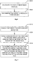
- it is determined whether the entire image (including the high-energy image and the low-energy image) is genuine (valid) based on the time when the second image was generated by the radiation imaging device, the generation time TIME (Create A) stored in the first image, and the time period TIME PERIOD (random) (being read at the header of the image file B) stored in the second image (for example, the low-energy image file B).
- TIME Create B TIME Create A + TIME PERIOD random If the above determination formula is not satisfied, the system will determine that associated images are not genuine, and an alarm signal will be issued.
- images of the object to be inspected may also be generated by means of other rays radiated by, for example, neutrons, protons, electrons, muons, heavy ions, and the like.
- ASICs Application Specific Integrated Circuits
- FPGAs Field Programmable Gate Arrays
- DSPs Digital Signal Processors
- ASICs Application Specific Integrated Circuits
- FPGAs Field Programmable Gate Arrays
- DSPs Digital Signal Processors
- those skilled in the art will recognize that some aspects of the embodiments disclosed herein, in whole or in part, may be equivalently implemented in integrated circuits, as one or more computer programs running on one or more computers (e.g., as one or more programs running on one or more computer systems), as one or more programs running on one or more processors (e.g., as one or more programs running on one or more microprocessors), as firmware, or as virtually any combination thereof, and that designing the circuitry and/or writing the code for the software and/or firmware would be well within the skill of those skilled in the art in ray of this disclosure.
- Examples of a signal bearing medium include, but are not limited to, the following: a recordable type medium such as a floppy disk, a hard disk drive, a Compact Disc (CD), a Digital Versatile Disk (DVD), a digital tape, a computer memory, etc.; and a transmission type medium such as a digital and/or an analog communication medium (e.g., a fiber optic cable, a waveguide, a wired communications link, a wireless communication link, etc.).
Landscapes
- Engineering & Computer Science (AREA)
- Physics & Mathematics (AREA)
- General Physics & Mathematics (AREA)
- Theoretical Computer Science (AREA)
- Software Systems (AREA)
- General Engineering & Computer Science (AREA)
- Health & Medical Sciences (AREA)
- Life Sciences & Earth Sciences (AREA)
- General Health & Medical Sciences (AREA)
- Computer Hardware Design (AREA)
- Computer Security & Cryptography (AREA)
- Mathematical Analysis (AREA)
- Geophysics (AREA)
- Computational Mathematics (AREA)
- Multimedia (AREA)
- Mathematical Optimization (AREA)
- Pure & Applied Mathematics (AREA)
- High Energy & Nuclear Physics (AREA)
- Bioethics (AREA)
- General Life Sciences & Earth Sciences (AREA)
- Technology Law (AREA)
- Chemical & Material Sciences (AREA)
- Analytical Chemistry (AREA)
- Biochemistry (AREA)
- Immunology (AREA)
- Pathology (AREA)
- Analysing Materials By The Use Of Radiation (AREA)
- Image Processing (AREA)
Abstract
Description
- Embodiments of the present disclosure relate to security of image files, and more particularly, to a method and device for generating associated images and a method and device for verifying associated images.
- In a radiation image inspecting system, objects are scanned by a radiation imaging device to generate high-energy and low-energy images. Then, the high-energy and low-energy image data is transmitted to an image inspecting workstation, and analyzed by professional software therein, so as to determine whether any dangerous, or otherwise undesirable, object is enclosed or present.
- In a security inspection device used for, for example, customs container cargo inspection, aviation security inspection, and non-destructive detection of large equipment, rays emitted by an X-ray source can penetrate enclosed compartments and enable the internal objects to be visualized, and are received by a detector at the other side. The absorbability of the rays is different due to different densities of different parts of the objects, and thus the intensity of signals output from the detectors is different. After performing image processing on signals of different intensity, the processed signals are displayed on the screen of a computer, which can clearly show the outline and shape of, for example, the objects inside a vehicle. Therefore, it is possible to know the objects in an enclosed compartment by simply viewing the display of the computer. As an example, in a large container inspecting system, when an image inspecting workstation acquires high-energy and low-energy images collected by the device, if someone copies pre-prepared images to the image library and replaces the actual images with the fake images, it may cause security problems with respect to the customs image inspecting service and bring losses to the customs security inspection.
- In view of one or more problems in the prior art, there is proposed a device for generating associated images and a method thereof and an device for verifying associated images and a method thereof, which can improve security in the inspecting process of security inspection images.
- In an aspect of the present disclosure, there is proposed a method of generating associated image files, comprising the steps of: scanning an object to be inspected, to obtain first image body data and second image body data that are associated with each other; creating a first image file based on the first image body data at a first time; generating a random time value; and generating a second image file associated with the first image file based on the second image body data at a second time, wherein the random time value is recorded in a file header of the second image file.
- According to an embodiment of the present disclosure, the method further comprises the step of: calculating a parameter value representing a size of the first image body data and/or the second image body data, and determining a recording position of the random time value in the file header of the second image file based on the parameter value.
- According to an embodiment of the present disclosure, the recording position is determined by the remainder after dividing the parameter value by a fixed value.
- According to an embodiment of the present disclosure, the step of generating the random time value comprises: setting a random time threshold based on a service processing speed and a network speed; generating the random time value based on the random time threshold.
- According to an embodiment of the present disclosure, the first image file and the second image file are generated for the same object to be inspected, and represent different physical properties of the object.
- According to an embodiment of the present disclosure, the first image file and the second image file are specifically the following files of the object to be inspected: a high-energy image file and a low-energy image file; or a CT (Computed Tomography) image file and a DR (Digital Radiography) image file; or a material type image file and an attenuation coefficient image file; or a first angle-of-view image file and a second angle-of-view image file.
- According to an embodiment of the present disclosure, the step of generating the random time value comprises: generating the random time value by utilizing a pseudo random number generator or a true random number generator.
- In another aspect of the present disclosure, there is proposed a method of verifying associated image files, comprising the steps of: reading a first image file and a second image file; parsing a generation time of the first image file, a generation time of the second image file and a random time value from a file header of one of the first image file and the second image file; determining whether the first image file and the second image file are genuine based on the random time value and the difference between the generation time of the first image file and the generation time of the second image file.
- According to an embodiment of the present disclosure, the first image file and the second image file are determined to be genuine (i.e. faithful representations of the originally-created files) if the difference between the generation time of the first image file and the generation time of the second image file equals to the random time value.
- In still another aspect of the present disclosure, there is proposed an imaging device, comprising: a scanning apparatus configured to scan an object to be inspected to obtain first image body data and second image body data that are associated with each other; a processor configured to create a first image file based on the first image body data at a first time, to generate a random time value, and to generate a second image file associated with the first image file based on the second image body data at a second time, wherein the random time value is recorded in a file header of the second image file.
- According to an embodiment of the present disclosure, the processor is further configured to calculate a parameter value representing a size of the first image body data and/or the second image body data, and to determine a recording position of the random time value in the file header of the second image file based on the parameter value.
- According to an embodiment of the present disclosure, the processor is configured to determine the recording position by the remainder after dividing the parameter value by a fixed value.
- According to an embodiment of the present disclosure, the processor is configured to set a random time threshold based on a service processing speed and a network speed, and to generate the random time value based on the random time threshold.
- According to an embodiment of the present disclosure, the random time value is generated by utilizing a pseudo random number generator or a true random number generator.
- In yet another aspect of the present disclosure, there is proposed an device for verifying associated image files, comprising: a memory, configured to store a plurality of image files; a processor, configured to read a first image file and a second image file, to parse a generation time of the first image file, a generation time of the second image file and a random time value from a file header of one of the first image file and the second image file, and to determine whether the first image file and the second image file are genuine based on the random time value and the difference between the generation time of the first image file and the generation time of the second image file.
- According to an embodiment of the present disclosure, the processor is configured to determine that the first image file and the second image file are genuine if the difference between the generation time of the first image file and the generation time of the second image file equals to the random time value.
- With the above-described technical scheme of the present disclosure, it is able to improve the security of the image inspecting process, and to determine whether actual security inspection images have been replaced with fake security inspection images.
- In order to better understand the present invention, the present invention will be described in detail with reference to the following drawings, in which:
-
Fig. 1 illustrates a schematic structural diagram of a security inspection device according to an embodiment of the present disclosure; -
Fig. 2 illustrates a schematic structural diagram of a computer apparatus in the security inspection device according to an embodiment of the present disclosure; -
Fig. 3 illustrates a schematic flowchart of a method of generating associated security inspection images according to an embodiment of the present disclosure; -
Fig. 4A illustrates a schematic structural diagram of an apparatus for generating a random time value according to an embodiment of the present disclosure; -
Fig. 4B illustrates a schematic structural diagram ofLFSR 401 in the apparatus shown inFig. 4A ; -
Fig. 4C illustrates an example of a calculation function used inCASE 404 in the apparatus shown inFig. 4A ; -
Fig. 5 illustrates a schematic structural diagram of another apparatus for generating a random time value according to an embodiment of the present disclosure; -
Fig. 6 illustrates an example of generating a random position for writing a time value into a file header of an image file according to an embodiment of the present disclosure; -
Fig. 7 illustrates a schematic flowchart of a method of verifying associated images according to an embodiment of the present disclosure. - The specific embodiments of the present invention will be described in detail below. It should be noted that the embodiments herein are used for illustration only, without limiting the present invention. In the description below, a number of specific details are explained to provide better understanding of the present invention. However, it is apparent to those skilled in the art that the present invention can be implemented without these specific details. In other instances, well known circuits, materials or methods are not described specifically so as not to obscure the present invention.
- Throughout the specification, the reference to "one embodiment," "an embodiment," "one example" or "an example" means that the specific features, structures or properties described in conjunction with the embodiment or example are included in at least one embodiment of the present invention. Therefore, the phrases "in one embodiment," "in an embodiment," "in one example" or "in an example" occurred in various positions throughout the specification may not necessarily refer to the same embodiment or example. Furthermore, specific features, structures or properties may be combined into one or more embodiments or examples in any appropriate combination and/or sub-combination. Moreover, it should be understood by those skilled in the art that the term "and/or" used herein means any and all combinations of one or more listed items.
- In view of one or more problems in the prior art, there is proposed a device for generating associated images and a method thereof and a device for verifying associated images and a method thereof. According to an embodiment of the present disclosure, an object to be inspected is scanned by, for example, a dual energy X-ray scanning device, to obtain first image body data (e.g., high-energy data) and second image body data (e.g., low-energy data) associated with each other. A first image file is created based on the first image body data at a first time and a random time value is generated. A second image file associated with the first image file is generated based on the second image body data at a second time after the random time value, wherein the random time value is recorded in a file header of the second image file. Thus, in the image verifying phase, the image can be verified based on the generation time of the image file and the random time value recorded in the file header. As an example, the first image file and the second image file are read, and the generation time of the first image file, the generation time of the second image file and the random time value are parsed from the file header of one of the first image file and the second image file. Then, it is determined whether the first image file and the second image file are genuine based on the random time value and the difference between the generation time of the first image file and the generation time of the second image file. Such approach can verify the first image file and second image file associated with each other, thereby improving the security of the security inspection device.
-
Fig. 1 illustrates a schematic structural diagram of a security inspection device according to an embodiment of the present disclosure. The security inspection device shown inFig. 1 includes a carrying (conveying)mechanism 140 which moves and carries anobject 130 to be inspected, such as a belt or the like, anX-ray source 110, adetector module 150, anacquisition circuit 160, acontroller 170, adata processing computer 180, and animage inspecting workstation 190 or the like. Theray source 110 includes an X-ray generator such as an X-ray machine or an electron linear accelerator, which generates an X-ray beam to scan theobject 130 to be inspected. In the above embodiment, theX-ray source 110 generates high-energy and low-energy X-rays in a switching mode, and scans the object to be inspected with the high-energy and low-energy X-rays. - As shown in
Fig. 1 , the carryingmechanism 140 passes through a scanning zone between theX-ray source 110 and thedetector 150 with theobject 130 to be inspected being carried thereon. In some embodiments, thedetector 150 and theacquisition circuit 160 are, for example, detectors and data acquisition devices having an integral modular structure, such as multiple rows of detectors, for detecting the X-rays penetrating the object to be inspected, to obtain an analog signal, and converting the analog signal into a digital signal so as to output radiation data of the object to be inspected with respect to X-rays. Thecontroller 170 is coupled to theX-ray source 110, thedetector module 150, and theacquisition circuit 160, and may control various portions of the overall system to operate synchronously. Thedata processing computer 180 may process the data acquired by the acquisition circuit, reconstruct the data, and output a result. - According to this embodiment, the
detector 150 and theacquisition circuit 160 are coupled to each other to obtain the radiation data of theobject 130 to be inspected. Theacquisition circuit 160 includes a data amplifying and shaping circuit which operates in either (current) integration mode or pulse (counting) mode. Theacquisition circuit 160 is coupled to thecontroller 170 and thedata processing computer 180 via its data output cable, and stores the acquired data in thedata processing computer 180 according to a trigger command. - In some embodiments, the
detector module 150 includes a plurality of detecting units which receive X-rays penetrating the object to be inspected. Thedata acquisition circuit 160 and thedetector module 150 are coupled to each other to convert signals generated by thedetector module 150 into detection data. Thecontroller 170 is connected to theX-ray source 110 via a control line CTRL1, connected to thedetector module 150 via a control line CTRL2, and connected to thedata acquisition circuit 160. Thecontroller 170 may control at least two X-ray generators of a plurality of X-ray generators in the X-ray source to generate high-energy and low-energy X-rays alternatively, which penetrate the object to be inspected as the object to be inspected moves. Furthermore, thecontroller 170 may control thedetector module 150 and thedata acquisition circuit 160 to obtain detection data corresponding to the at least two X-ray generators, respectively. Thedata processing computer 180 may reconstruct images, of the object to be inspected, of at least two energies based on the detection data. - The obtained radiation images are transmitted to the
image inspecting workstation 190 in a wired or wireless manner. The images generated by scanning are manually inspected at theimage inspecting workstation 190, so as to determine whether the object to be inspected is an undesired object, e.g. a dangerous object or an illegal object. -
Fig. 2 illustrates a structural block diagram of thedata processing computer 180 shown inFig. 1 . As shown inFig. 2 , the data acquired by theacquisition circuit 160 is stored in amemory 181 via aninterface unit 187 and abus 188. Configuration information and programs of the data processing computer are stored in a read only memory (ROM) 182. A random access memory (RAM) 183 may temporarily store various data during the operation of aprocessor 185. In addition, a computer program for performing data processing is also stored in thememory 181. Aninternal bus 188 is connected to thememory 181, read onlymemory 182,random access memory 183,input device 184,processor 185,display device 186, andinterface unit 187 described above. - After an operation command is input by an user via the
input device 184 such as a keyboard and a mouse, the instruction code of the computer program commands theprocessor 185 to execute a predetermined data reconstruction algorithm, and to display a data processing result on the display device 186 (such as an LCD display), or to output the processing result in the way of hard copying such as printing directly. - Although it is shown in
Fig. 1 that theobject 130 to be inspected is X-ray scanned, it will be understood by those skilled in the art that, when thecarrying mechanism 140 rotates or theX-ray source 110 and thedetector 150 rotates around the object to be inspected, a dual energy CT scanning on the object to be inspected may be realized, and thus high-energy and low-energy CT images associated with each other may be obtained. It will be appreciated by those skilled in the art that, in other embodiments, two images associated with each other, for example, images of different angles-of-view of the same object (such as a first angle-of-view image and a second angle-of-view image), a CT image and a DR image, or a material type image and an attenuation coefficient image of an object to be inspected or the like, may be generated for security inspection. -
Fig. 3 illustrates a schematic flowchart of a method of generating associated security inspection images according to an embodiment of the present disclosure. As shown inFig. 3 , in an embodiment of the present disclosure, images are stored in thememory 183, and a non-constant time difference among a plurality of images is generated by a random delay processing mechanism. The time difference is stored in an image file (such as a low-energy image). When image processing is performed at a service site (for example, the image inspecting station 190), the time difference information obtained from the images may be used to conduct verification, so as to determine whether the images in theimage inspecting workstation 190 have been tampered with. - Referring to
Fig. 3 , in step S310, anobject 130 to be inspected may be scanned by a security inspection device, to obtain first image body data and second image body data which are associated with each other, for example, high-energy data and low-energy data. It should be noted that, however, no image file has been generated yet at that time. - Then, in step S320, a first image file is created based on the first image body data at a first time. As an example, in the case where the image body data is known, the image file is generated in a desired format in which the image body data described above is filled in the image body portion, and related attribute data (for example, generation time) is filled in the image header portion, and the like.
- In step S330, a random time value is generated. In step S340, a second image file associated with the first image file is generated based on the second image body data at a second time, wherein the random time value is recorded in the file header of the second image file.
- As an example, immediately after generating high-energy and low-energy image data of the
object 130 to be inspected by the security inspection device, any one of a high-energy image file or a low-energy image file, for example, the high-energy image file (named A), is generated in the system image library, and TIME(Create A) is stored in the file header. The other image file, for example, the low-energy image file (named B), is not generated immediately, but is temporarily stored in a memory. In the present embodiment, the system sets a random time threshold based on the service processing speed and the network speed in the deployment environment, and generates a random time value (TRandom) by utilizing a random time generator. The system waits until a time period specified by the random time value has elapsed. Then the image file B is generated and written into a disk. Simultaneously, the time period specified by the random time value and the generation time of the image file B are recorded in the file header of the image file B. The threshold is used to control the range of the generated random time value. For example, if the threshold is set to 2 seconds, the randomly generated time value should be in the range of 0 to 2 seconds. - The above random time value can be generated by software or by hardware. The manner in which the random time value is generated is not particularly limited in embodiments of the present disclosure. For example, in the case where a pseudo-random number is generated by the software, Rand() Function in C language can be called to generate the pseudo-random number.
-
Fig. 4A illustrates a schematic structural diagram of an apparatus for generating a random time value according to an embodiment of the present disclosure.Fig. 4B illustrates a schematic structural diagram ofLFSR 401 in the apparatus shown inFig. 4A .Fig. 4C illustrates an example of a calculation function used inCASE 404 in the apparatus shown inFig. 4A . -
Fig. 4A illustrates the generation of a pseudo random number by means of a combination of a linear feedback shift register (LFSR) 401 and a cellular automata shift register (CASE) 404. The random number generator shown inFig. 4A includes the linear feedback shift register (LFSR) 401, the cellularautomata shift register 404, two 32-bit multiplexers gate 403. As shown inFig. 4A , the linearfeedback shift register 401 receives a clock signal at its input, and transmits a first output signal from the output of theLFSR 401 to the input of themultiplexer 402. A first multiplexed signal is generated at the output of themultiplexer 402. - The cellular
automata shift register 404 receives a clock signal and transmits a second output signal from the output of the cellularautomata shift register 404 to the input of themultiplexer 405. A second multiplexed signal is generated at the output of themultiplexer 405. The respective outputs ofmultiplexers XOR gate 403, respectively, and a pseudo random number is generated at the output of theXOR gate 403. - As shown in
Fig. 4B , theLFSR 401 may be a 43-bit LFSR and may consist of two parts, a 43-bit shift register 412 and afeedback unit 411. Thefeedback unit 411 generates one new bit to add into the bit stream by calculating the input bit sequence, so that all bits of the bit stream are shifted to the right by one bit simultaneously. As a result, the rightmost bit is the output result. In the example ofFig.4B , the feedback function employed by the feedback unit is as follows:

- The
CASE 404 may be a 37-bit CASE (Cellular Automata Shift Register), for example, which calculates each bit of the bit sequence by a calculation function unit, inserts the calculated new bit at the leftmost end of the bit sequence to have all bits of the bit stream shift to the right. As a result, the bit being shifted out is the output bit. The calculation functions used by the 37-bit cellular automata pseudo-random generator herein may be CA90 and CA150, as shown inFig. 4C . -
Fig. 5 illustrates a schematic structural diagram of another apparatus for generating a random time value according to an embodiment of the present disclosure. As shown inFig. 5 , a schematic structural diagram of a physical true random number generator (PTRNG) is provided. Physical random number generators are based on the random characteristics of physical phenomena in nature, for example, molecular motion, decay of elements, thermal noise of resistors and diodes. For the PTRNG, there is no initial sequence or seed, and no algorithm can predetermine what is to be output next. During the operation of the PTRNG system according to one embodiment of the apparatus ofFig.5 , an analog thermal noise signal is generated by anoise source 501 first. Aprocessing circuit 502 includes, for example, a sampling circuit and an AID converter, configured to convert the thermal noise signal into a digital signal, or the like. Then, the digital signal is output to thedata processing computer 180 via anoutput interface 503, thereby resulting in random numbers that are more uniform in distribution and relatively independent of one another. - According to other embodiments, when a time parameter generated by a random time generator is added to a file header of a low-energy image file, the byte code may not be written at a fixed position, but may be written at a random position instead, for example, at a random position B of the file header of the image file. The method of determining the random position can be performed as shown in
Fig. 6 below. -
Fig. 6 illustrates a schematic structural diagram of an apparatus for generating a random position value according to an embodiment of the present disclosure. As shown inFig. 6 , the size C of an image body portion is calculated in step S610. For example, the size of the high-energy image body or the size of the low-energy image body is calculated. Then, in step S620, the random position B of the random time value in the file header is calculated by the remainder after dividing the calculated size C of the image body by a fixed value S. Those skilled in the art will understand that other ways of determining the position of the random time value in the file header may be employed. -
Fig. 7 illustrates a schematic flowchart of a method of verifying (validating) associated images according to an embodiment of the present disclosure. In the embodiment shown inFig. 7 , after entering the image verification process, it is determined whether the entire image (including the high-energy image and the low-energy image) is genuine (valid) based on the time when the second image was generated by the radiation imaging device, the generation time TIME (Create A) stored in the first image, and the time period TIME PERIOD (random) (being read at the header of the image file B) stored in the second image (for example, the low-energy image file B). - The determination formula for the generation time of the image B is as follows:

- With the above embodiments, it is able to bring great benefits to the robustness of the customs image inspecting service, to prevent the replacement of actual images with fake images, and to improve the security level of customs security inspection. The same method can also be applied in other fields to conduct a verification of relevancy according to the relevance of objects/events in the field. More particularly, independent entities are placed in a system with associated attributes, and then it may be determined whether the entities are genuine and valid according to the associated attributes of the system.
- Moreover, although the above description is directed to high-energy and low-energy images, those skilled in the art will appreciate that two images generated by performing radiation imaging on the same object can be used as associated images. Furthermore, although Radiography imaging is described above, those skilled in the art will appreciate that, images of the object to be inspected may also be generated by means of other rays radiated by, for example, neutrons, protons, electrons, muons, heavy ions, and the like.
- The foregoing detailed description has set forth various embodiments of a device for generating associated images and a method thereof and a device for verifying associated images and a method thereof via the use of diagrams, flowcharts, and/or examples. In a case that such diagrams, flowcharts, and/or examples contain one or more functions and/or operations, it will be understood by those skilled in the art that each function and/or operation within such diagrams, flowcharts or examples may be implemented, individually and/or collectively, by a wide range of structures, hardware, software, firmware, or virtually any combination thereof. In one embodiment, several portions of the subject matter described in the embodiments of the present invention may be implemented via Application Specific Integrated Circuits (ASICs), Field Programmable Gate Arrays (FPGAs), Digital Signal Processors (DSPs), or other integrated formats. However, those skilled in the art will recognize that some aspects of the embodiments disclosed herein, in whole or in part, may be equivalently implemented in integrated circuits, as one or more computer programs running on one or more computers (e.g., as one or more programs running on one or more computer systems), as one or more programs running on one or more processors (e.g., as one or more programs running on one or more microprocessors), as firmware, or as virtually any combination thereof, and that designing the circuitry and/or writing the code for the software and/or firmware would be well within the skill of those skilled in the art in ray of this disclosure. In addition, those skilled in the art will appreciate that the mechanisms of the subject matter described herein are capable of being distributed as a program product in a variety of forms, and that an illustrative embodiment of the subject matter described herein applies regardless of the particular type of signal bearing medium used to actually carry out the distribution. Examples of a signal bearing medium include, but are not limited to, the following: a recordable type medium such as a floppy disk, a hard disk drive, a Compact Disc (CD), a Digital Versatile Disk (DVD), a digital tape, a computer memory, etc.; and a transmission type medium such as a digital and/or an analog communication medium (e.g., a fiber optic cable, a waveguide, a wired communications link, a wireless communication link, etc.).
- While the present invention has been described with reference to several typical embodiments, it is apparent to those skilled in the art that the terms are used for illustration and explanation purpose and not for limitation. The present invention may be practiced in various forms without departing from the spirit or essence of the present invention. It should be understood that the embodiments are not limited to any of the foregoing details, and shall be interpreted broadly within the scope as defined by the following claims. Therefore, all of modifications and alternatives falling within the scope of the claims or equivalents thereof are to be encompassed by the claims as attached.
Claims (15)
- A method of generating associated image files, comprising:scanning an object to be inspected to obtain first image body data and second image body data that are associated with each other;creating a first image file based on the first image body data at a first time;generating a random time value; andgenerating a second image file associated with the first image file based on the second image body data at a second time, wherein the random time value is recorded in a file header of the second image file.
- The method of claim 1, further comprising:
calculating a parameter value representing a size of the first image body data and/or the second image body data, and determining a recording position of the random time value in the file header of the second image file based on the parameter value. - The method of claim 1, wherein the recording position is determined by the remainder after dividing the parameter value by a fixed value.
- The method of claim 1, wherein the generating a random time value comprises:setting a random time threshold based on a service processing speed and a network speed;generating the random time value based on the random time threshold.
- The method of any one of claims 1 to 4, wherein the first image file and the second image file are generated for the same object to be inspected, and represent different physical properties of the object, respectively; and
wherein the first image file and the second image file are the following files of the object to be inspected:a high-energy image file and a low-energy image file; ora CT image file and a DR image file; ora material type image file and an attenuation coefficient image file; ora first angle-of-view image file and a second angle-of-view image file. - The method of claim 1, wherein the generating a random time value comprises:
generating the random time value by utilizing a pseudo random number generator or a true random number generator. - A method of verifying associated image files, comprising the steps of:reading a first image file and a second image file;parsing a generation time of the first image file, a generation time of the second image file and a random time value from a file header of one of the first image file and the second image file;determining whether the first image file and the second image file are valid based on the random time value and the difference between the generation time of the first image file and the generation time of the second image file.
- The method of claim 7, wherein the first image file and the second image file are determined to be valid if the difference between the generation time of the first image file and the generation time of the second image file equals to the random time value.
- The method of any one of claims 7-8, wherein the first image file and the second image file are generated for the same object to be inspected, and represent different physical properties of the object; and
wherein the first image file and the second image file are the following files of the object to be inspected:a high-energy image file and a low-energy image file; ora CT image file and a DR image file; ora material type image file and an attenuation coefficient image file; ora first angle-of-view image file and a second angle-of-view image file. - An imaging device, comprising:a scanning apparatus (110,150-170) configured to scan an object (130) to be inspected to obtain first image body data and second image body data that are associated with each other;a processor (185) configured to:create a first image file based on the first image body data at a first time;generate a random time value; andgenerate a second image file associated with the first image file based on the second image body data at a second time, wherein the random time value is recorded in a file header of the second image file.
- The imaging device of claim 10, wherein the processor (185) is further configured to:
calculate a parameter value representing a size of the first image body data and/or the second image body data, and determine a recording position of the random time value in the file header of the second image file based on the parameter value. - The imaging device according to claim 11, wherein the processor (185) is configured to determine the recording position by the remainder after dividing the parameter value by a fixed value.
- The imaging device of claim 10, wherein the processor (185) is configured to:set a random time threshold based on a service processing speed and a network speed;generate the random time value based on the random time threshold.
- The imaging device of any one of claims 10 to 13, wherein the first image file and the second image file are generated for the same object to be inspected, and represent different physical properties of the object, respectively; and
wherein the first image file and the second image file are the following files of the object to be inspected:a high-energy image file and a low-energy image file; ora CT image file and a DR image file; ora material type image file and an attenuation coefficient image file; ora first angle-of-view image file and a second angle-of-view image file. - The imaging device of claim 10, wherein the random time value is generated by utilizing a pseudo random number generator (401-405) or a true random number generator (501-503).
Applications Claiming Priority (1)
| Application Number | Priority Date | Filing Date | Title |
|---|---|---|---|
| CN201710905603.XA CN107526948B (en) | 2017-09-28 | 2017-09-28 | Method and device for generating associated image and image verification method and device |
Publications (2)
| Publication Number | Publication Date |
|---|---|
| EP3462407A1 true EP3462407A1 (en) | 2019-04-03 |
| EP3462407B1 EP3462407B1 (en) | 2020-10-28 |
Family
ID=60737684
Family Applications (1)
| Application Number | Title | Priority Date | Filing Date |
|---|---|---|---|
| EP18186889.4A Not-in-force EP3462407B1 (en) | 2017-09-28 | 2018-08-01 | Method and device for generating associated images and verifying them |
Country Status (3)
| Country | Link |
|---|---|
| EP (1) | EP3462407B1 (en) |
| CN (1) | CN107526948B (en) |
| WO (1) | WO2019062308A1 (en) |
Families Citing this family (2)
| Publication number | Priority date | Publication date | Assignee | Title |
|---|---|---|---|---|
| CN107526948B (en) * | 2017-09-28 | 2023-08-25 | 同方威视技术股份有限公司 | Method and device for generating associated image and image verification method and device |
| CN111782884B (en) * | 2020-06-10 | 2024-09-17 | 北京金和网络股份有限公司 | Event information management method, system and computer readable storage medium |
Citations (2)
| Publication number | Priority date | Publication date | Assignee | Title |
|---|---|---|---|---|
| US20040201751A1 (en) * | 2002-01-03 | 2004-10-14 | Genevieve Bell | Secure digital photography system |
| US20080259404A1 (en) * | 2007-04-19 | 2008-10-23 | Fumio Yoshizawa | Image distributing apparatus and image forming apparatus |
Family Cites Families (18)
| Publication number | Priority date | Publication date | Assignee | Title |
|---|---|---|---|---|
| EP1055989A1 (en) * | 1999-05-28 | 2000-11-29 | Hewlett-Packard Company | System for digitally signing a document |
| CN101034429A (en) * | 2000-02-29 | 2007-09-12 | 通用电器横河医疗系统株式会社 | Method for preventing illegal copying date processing device and medical treatment imaging device |
| JP4734726B2 (en) * | 2000-03-14 | 2011-07-27 | ソニー株式会社 | Information providing apparatus and method, information processing apparatus and method, program storage medium, and program |
| US8849068B2 (en) * | 2005-04-08 | 2014-09-30 | Canon Kabushiki Kaisha | Image management system, image management method, and program |
| US7402807B2 (en) * | 2005-11-02 | 2008-07-22 | Siemens Medical Solutions Usa, Inc. | Method for reducing an electronic time coincidence window in positron emission tomography |
| JP4548520B2 (en) * | 2008-07-02 | 2010-09-22 | ソニー株式会社 | Coefficient generation apparatus and method, image generation apparatus and method, and program |
| US8208633B2 (en) * | 2008-11-24 | 2012-06-26 | Pitney Bowes Inc. | Method and system for securing communications in a metering device |
| CN102855235B (en) * | 2011-06-27 | 2016-03-30 | 联想(北京)有限公司 | For e-file sets up the method and apparatus of relative time information |
| US8775377B1 (en) * | 2012-07-25 | 2014-07-08 | Symantec Corporation | Efficient data backup with change tracking |
| RU2012154657A (en) * | 2012-12-17 | 2014-06-27 | ЭлЭсАй Корпорейшн | METHODS AND DEVICE FOR COMBINING IMAGES WITH DEPTH GENERATED USING DIFFERENT METHODS FOR FORMING IMAGES WITH DEPTH |
| EP2765774A1 (en) * | 2013-02-06 | 2014-08-13 | Koninklijke Philips N.V. | System for generating an intermediate view image |
| US9940972B2 (en) * | 2013-08-15 | 2018-04-10 | Cellular South, Inc. | Video to data |
| JP6149741B2 (en) * | 2014-01-24 | 2017-06-21 | 富士ゼロックス株式会社 | Information processing apparatus and program |
| KR101664432B1 (en) * | 2014-02-12 | 2016-10-10 | 삼성전자주식회사 | Computer tomography apparatus and method for displaying a computer tomography image thereof |
| RU2633185C2 (en) * | 2014-05-28 | 2017-10-11 | Сергей Валентинович Баушев | Method of creating digital photos protected from forgery, and device for its implementation |
| US9917854B2 (en) * | 2015-09-30 | 2018-03-13 | Emc Corporation | Security detection |
| CN106707295B (en) * | 2017-01-03 | 2019-05-17 | 中国科学院上海光学精密机械研究所 | Three-dimensional imaging device and imaging method based on time correlation |
| CN107526948B (en) * | 2017-09-28 | 2023-08-25 | 同方威视技术股份有限公司 | Method and device for generating associated image and image verification method and device |
-
2017
- 2017-09-28 CN CN201710905603.XA patent/CN107526948B/en active Active
-
2018
- 2018-07-25 WO PCT/CN2018/097032 patent/WO2019062308A1/en not_active Ceased
- 2018-08-01 EP EP18186889.4A patent/EP3462407B1/en not_active Not-in-force
Patent Citations (2)
| Publication number | Priority date | Publication date | Assignee | Title |
|---|---|---|---|---|
| US20040201751A1 (en) * | 2002-01-03 | 2004-10-14 | Genevieve Bell | Secure digital photography system |
| US20080259404A1 (en) * | 2007-04-19 | 2008-10-23 | Fumio Yoshizawa | Image distributing apparatus and image forming apparatus |
Non-Patent Citations (1)
| Title |
|---|
| ARUN ANOOP M: "Image forgery and its detection: A survey", 2015 INTERNATIONAL CONFERENCE ON INNOVATIONS IN INFORMATION, EMBEDDED AND COMMUNICATION SYSTEMS (ICIIECS), IEEE, 19 March 2015 (2015-03-19), pages 1 - 9, XP033192551, ISBN: 978-1-4799-6817-6, [retrieved on 20150812], DOI: 10.1109/ICIIECS.2015.7193253 * |
Also Published As
| Publication number | Publication date |
|---|---|
| EP3462407B1 (en) | 2020-10-28 |
| WO2019062308A1 (en) | 2019-04-04 |
| CN107526948A (en) | 2017-12-29 |
| CN107526948B (en) | 2023-08-25 |
Similar Documents
| Publication | Publication Date | Title |
|---|---|---|
| US10379252B2 (en) | Methods and devices for estimating weight of an object to be inspected in an inspection system | |
| US7492862B2 (en) | Computed tomography cargo inspection system and method | |
| Chrząszcz et al. | HECATE: A long-lived particle detector concept for the FCC-ee or CEPC | |
| CN105806856B (en) | Dual Energy Ray Imaging Method and System | |
| CN110660111B (en) | PET scattering correction and image reconstruction method, device and equipment | |
| Luo et al. | Hybrid model for muon tomography and quantitative analysis of image quality | |
| CN101647706A (en) | Image reconstruction method for high-energy double-energy CT system | |
| JP2009534631A (en) | Dirty isotope PET reconstruction | |
| CN103728324B (en) | A kind of nuclear fuel assembly nondestructive detection device for high-energy X-ray | |
| Ji et al. | A novel 4D resolution imaging method for low and medium atomic number objects at the centimeter scale by coincidence detection technique of cosmic-ray muon and its secondary particles | |
| JP2018189598A (en) | PET apparatus with positron lifetime measurement function, and positron lifetime measurement method in PET apparatus | |
| Sullivan et al. | Validation of a Bayesian-based isotope identification algorithm | |
| EP3462407B1 (en) | Method and device for generating associated images and verifying them | |
| CN103460075A (en) | Methods and databases for identifying nuclides | |
| Song et al. | Inverse Compton emission from millisecond pulsars in the Galactic bulge | |
| JP6917356B2 (en) | Decomposition method and equipment by combining main components | |
| McCabe et al. | In silico modeling of a clinical photon‐counting CT system: verification and validation | |
| Göppel et al. | Dose‐efficiency quantification of computed tomography systems using a model‐observer | |
| JP2009122043A (en) | Material discrimination testing apparatus and method therefor | |
| EP2749901B1 (en) | Back-scattering inspection systems and methods for human body | |
| CN114518607A (en) | Object Detection Method and System | |
| Wang et al. | Image-based synthetic CT: simulating arbitrary low dose single and dual energy protocols from dual energy images | |
| JP6803768B2 (en) | Material analyzer, material analysis method and X-ray CT equipment | |
| Haith | Radiographic imaging of subsea pipelines | |
| CN110988966A (en) | Neutron and gamma ray compound photography method and system based on CLYC crystal |
Legal Events
| Date | Code | Title | Description |
|---|---|---|---|
| PUAI | Public reference made under article 153(3) epc to a published international application that has entered the european phase |
Free format text: ORIGINAL CODE: 0009012 |
|
| STAA | Information on the status of an ep patent application or granted ep patent |
Free format text: STATUS: REQUEST FOR EXAMINATION WAS MADE |
|
| 17P | Request for examination filed |
Effective date: 20180801 |
|
| AK | Designated contracting states |
Kind code of ref document: A1 Designated state(s): AL AT BE BG CH CY CZ DE DK EE ES FI FR GB GR HR HU IE IS IT LI LT LU LV MC MK MT NL NO PL PT RO RS SE SI SK SM TR |
|
| AX | Request for extension of the european patent |
Extension state: BA ME |
|
| GRAP | Despatch of communication of intention to grant a patent |
Free format text: ORIGINAL CODE: EPIDOSNIGR1 |
|
| STAA | Information on the status of an ep patent application or granted ep patent |
Free format text: STATUS: GRANT OF PATENT IS INTENDED |
|
| INTG | Intention to grant announced |
Effective date: 20200514 |
|
| GRAS | Grant fee paid |
Free format text: ORIGINAL CODE: EPIDOSNIGR3 |
|
| GRAA | (expected) grant |
Free format text: ORIGINAL CODE: 0009210 |
|
| STAA | Information on the status of an ep patent application or granted ep patent |
Free format text: STATUS: THE PATENT HAS BEEN GRANTED |
|
| AK | Designated contracting states |
Kind code of ref document: B1 Designated state(s): AL AT BE BG CH CY CZ DE DK EE ES FI FR GB GR HR HU IE IS IT LI LT LU LV MC MK MT NL NO PL PT RO RS SE SI SK SM TR |
|
| REG | Reference to a national code |
Ref country code: GB Ref legal event code: FG4D |
|
| REG | Reference to a national code |
Ref country code: CH Ref legal event code: EP |
|
| REG | Reference to a national code |
Ref country code: DE Ref legal event code: R096 Ref document number: 602018009080 Country of ref document: DE |
|
| REG | Reference to a national code |
Ref country code: AT Ref legal event code: REF Ref document number: 1328968 Country of ref document: AT Kind code of ref document: T Effective date: 20201115 |
|
| REG | Reference to a national code |
Ref country code: IE Ref legal event code: FG4D |
|
| REG | Reference to a national code |
Ref country code: AT Ref legal event code: MK05 Ref document number: 1328968 Country of ref document: AT Kind code of ref document: T Effective date: 20201028 |
|
| REG | Reference to a national code |
Ref country code: NL Ref legal event code: MP Effective date: 20201028 |
|
| PG25 | Lapsed in a contracting state [announced via postgrant information from national office to epo] |
Ref country code: GR Free format text: LAPSE BECAUSE OF FAILURE TO SUBMIT A TRANSLATION OF THE DESCRIPTION OR TO PAY THE FEE WITHIN THE PRESCRIBED TIME-LIMIT Effective date: 20210129 Ref country code: NO Free format text: LAPSE BECAUSE OF FAILURE TO SUBMIT A TRANSLATION OF THE DESCRIPTION OR TO PAY THE FEE WITHIN THE PRESCRIBED TIME-LIMIT Effective date: 20210128 Ref country code: PT Free format text: LAPSE BECAUSE OF FAILURE TO SUBMIT A TRANSLATION OF THE DESCRIPTION OR TO PAY THE FEE WITHIN THE PRESCRIBED TIME-LIMIT Effective date: 20210301 Ref country code: RS Free format text: LAPSE BECAUSE OF FAILURE TO SUBMIT A TRANSLATION OF THE DESCRIPTION OR TO PAY THE FEE WITHIN THE PRESCRIBED TIME-LIMIT Effective date: 20201028 Ref country code: FI Free format text: LAPSE BECAUSE OF FAILURE TO SUBMIT A TRANSLATION OF THE DESCRIPTION OR TO PAY THE FEE WITHIN THE PRESCRIBED TIME-LIMIT Effective date: 20201028 |
|
| REG | Reference to a national code |
Ref country code: LT Ref legal event code: MG4D |
|
| PG25 | Lapsed in a contracting state [announced via postgrant information from national office to epo] |
Ref country code: BG Free format text: LAPSE BECAUSE OF FAILURE TO SUBMIT A TRANSLATION OF THE DESCRIPTION OR TO PAY THE FEE WITHIN THE PRESCRIBED TIME-LIMIT Effective date: 20210128 Ref country code: SE Free format text: LAPSE BECAUSE OF FAILURE TO SUBMIT A TRANSLATION OF THE DESCRIPTION OR TO PAY THE FEE WITHIN THE PRESCRIBED TIME-LIMIT Effective date: 20201028 Ref country code: LV Free format text: LAPSE BECAUSE OF FAILURE TO SUBMIT A TRANSLATION OF THE DESCRIPTION OR TO PAY THE FEE WITHIN THE PRESCRIBED TIME-LIMIT Effective date: 20201028 Ref country code: PL Free format text: LAPSE BECAUSE OF FAILURE TO SUBMIT A TRANSLATION OF THE DESCRIPTION OR TO PAY THE FEE WITHIN THE PRESCRIBED TIME-LIMIT Effective date: 20201028 Ref country code: IS Free format text: LAPSE BECAUSE OF FAILURE TO SUBMIT A TRANSLATION OF THE DESCRIPTION OR TO PAY THE FEE WITHIN THE PRESCRIBED TIME-LIMIT Effective date: 20210228 Ref country code: ES Free format text: LAPSE BECAUSE OF FAILURE TO SUBMIT A TRANSLATION OF THE DESCRIPTION OR TO PAY THE FEE WITHIN THE PRESCRIBED TIME-LIMIT Effective date: 20201028 Ref country code: AT Free format text: LAPSE BECAUSE OF FAILURE TO SUBMIT A TRANSLATION OF THE DESCRIPTION OR TO PAY THE FEE WITHIN THE PRESCRIBED TIME-LIMIT Effective date: 20201028 |
|
| PG25 | Lapsed in a contracting state [announced via postgrant information from national office to epo] |
Ref country code: HR Free format text: LAPSE BECAUSE OF FAILURE TO SUBMIT A TRANSLATION OF THE DESCRIPTION OR TO PAY THE FEE WITHIN THE PRESCRIBED TIME-LIMIT Effective date: 20201028 Ref country code: NL Free format text: LAPSE BECAUSE OF FAILURE TO SUBMIT A TRANSLATION OF THE DESCRIPTION OR TO PAY THE FEE WITHIN THE PRESCRIBED TIME-LIMIT Effective date: 20201028 |
|
| REG | Reference to a national code |
Ref country code: DE Ref legal event code: R097 Ref document number: 602018009080 Country of ref document: DE |
|
| PG25 | Lapsed in a contracting state [announced via postgrant information from national office to epo] |
Ref country code: RO Free format text: LAPSE BECAUSE OF FAILURE TO SUBMIT A TRANSLATION OF THE DESCRIPTION OR TO PAY THE FEE WITHIN THE PRESCRIBED TIME-LIMIT Effective date: 20201028 Ref country code: SK Free format text: LAPSE BECAUSE OF FAILURE TO SUBMIT A TRANSLATION OF THE DESCRIPTION OR TO PAY THE FEE WITHIN THE PRESCRIBED TIME-LIMIT Effective date: 20201028 Ref country code: LT Free format text: LAPSE BECAUSE OF FAILURE TO SUBMIT A TRANSLATION OF THE DESCRIPTION OR TO PAY THE FEE WITHIN THE PRESCRIBED TIME-LIMIT Effective date: 20201028 Ref country code: SM Free format text: LAPSE BECAUSE OF FAILURE TO SUBMIT A TRANSLATION OF THE DESCRIPTION OR TO PAY THE FEE WITHIN THE PRESCRIBED TIME-LIMIT Effective date: 20201028 Ref country code: EE Free format text: LAPSE BECAUSE OF FAILURE TO SUBMIT A TRANSLATION OF THE DESCRIPTION OR TO PAY THE FEE WITHIN THE PRESCRIBED TIME-LIMIT Effective date: 20201028 Ref country code: CZ Free format text: LAPSE BECAUSE OF FAILURE TO SUBMIT A TRANSLATION OF THE DESCRIPTION OR TO PAY THE FEE WITHIN THE PRESCRIBED TIME-LIMIT Effective date: 20201028 |
|
| PG25 | Lapsed in a contracting state [announced via postgrant information from national office to epo] |
Ref country code: DK Free format text: LAPSE BECAUSE OF FAILURE TO SUBMIT A TRANSLATION OF THE DESCRIPTION OR TO PAY THE FEE WITHIN THE PRESCRIBED TIME-LIMIT Effective date: 20201028 |
|
| PLBE | No opposition filed within time limit |
Free format text: ORIGINAL CODE: 0009261 |
|
| STAA | Information on the status of an ep patent application or granted ep patent |
Free format text: STATUS: NO OPPOSITION FILED WITHIN TIME LIMIT |
|
| 26N | No opposition filed |
Effective date: 20210729 |
|
| PG25 | Lapsed in a contracting state [announced via postgrant information from national office to epo] |
Ref country code: IT Free format text: LAPSE BECAUSE OF FAILURE TO SUBMIT A TRANSLATION OF THE DESCRIPTION OR TO PAY THE FEE WITHIN THE PRESCRIBED TIME-LIMIT Effective date: 20201028 Ref country code: AL Free format text: LAPSE BECAUSE OF FAILURE TO SUBMIT A TRANSLATION OF THE DESCRIPTION OR TO PAY THE FEE WITHIN THE PRESCRIBED TIME-LIMIT Effective date: 20201028 |
|
| PG25 | Lapsed in a contracting state [announced via postgrant information from national office to epo] |
Ref country code: SI Free format text: LAPSE BECAUSE OF FAILURE TO SUBMIT A TRANSLATION OF THE DESCRIPTION OR TO PAY THE FEE WITHIN THE PRESCRIBED TIME-LIMIT Effective date: 20201028 |
|
| REG | Reference to a national code |
Ref country code: DE Ref legal event code: R119 Ref document number: 602018009080 Country of ref document: DE |
|
| REG | Reference to a national code |
Ref country code: CH Ref legal event code: PL |
|
| PG25 | Lapsed in a contracting state [announced via postgrant information from national office to epo] |
Ref country code: MC Free format text: LAPSE BECAUSE OF FAILURE TO SUBMIT A TRANSLATION OF THE DESCRIPTION OR TO PAY THE FEE WITHIN THE PRESCRIBED TIME-LIMIT Effective date: 20201028 |
|
| REG | Reference to a national code |
Ref country code: BE Ref legal event code: MM Effective date: 20210831 |
|
| PG25 | Lapsed in a contracting state [announced via postgrant information from national office to epo] |
Ref country code: LI Free format text: LAPSE BECAUSE OF NON-PAYMENT OF DUE FEES Effective date: 20210831 Ref country code: CH Free format text: LAPSE BECAUSE OF NON-PAYMENT OF DUE FEES Effective date: 20210831 |
|
| PG25 | Lapsed in a contracting state [announced via postgrant information from national office to epo] |
Ref country code: IS Free format text: LAPSE BECAUSE OF FAILURE TO SUBMIT A TRANSLATION OF THE DESCRIPTION OR TO PAY THE FEE WITHIN THE PRESCRIBED TIME-LIMIT Effective date: 20210228 Ref country code: LU Free format text: LAPSE BECAUSE OF NON-PAYMENT OF DUE FEES Effective date: 20210801 |
|
| PG25 | Lapsed in a contracting state [announced via postgrant information from national office to epo] |
Ref country code: IE Free format text: LAPSE BECAUSE OF NON-PAYMENT OF DUE FEES Effective date: 20210801 Ref country code: FR Free format text: LAPSE BECAUSE OF NON-PAYMENT OF DUE FEES Effective date: 20210831 Ref country code: DE Free format text: LAPSE BECAUSE OF NON-PAYMENT OF DUE FEES Effective date: 20220301 Ref country code: BE Free format text: LAPSE BECAUSE OF NON-PAYMENT OF DUE FEES Effective date: 20210831 |
|
| GBPC | Gb: european patent ceased through non-payment of renewal fee |
Effective date: 20220801 |
|
| PG25 | Lapsed in a contracting state [announced via postgrant information from national office to epo] |
Ref country code: CY Free format text: LAPSE BECAUSE OF FAILURE TO SUBMIT A TRANSLATION OF THE DESCRIPTION OR TO PAY THE FEE WITHIN THE PRESCRIBED TIME-LIMIT Effective date: 20201028 |
|
| PG25 | Lapsed in a contracting state [announced via postgrant information from national office to epo] |
Ref country code: HU Free format text: LAPSE BECAUSE OF FAILURE TO SUBMIT A TRANSLATION OF THE DESCRIPTION OR TO PAY THE FEE WITHIN THE PRESCRIBED TIME-LIMIT; INVALID AB INITIO Effective date: 20180801 |
|
| PG25 | Lapsed in a contracting state [announced via postgrant information from national office to epo] |
Ref country code: GB Free format text: LAPSE BECAUSE OF NON-PAYMENT OF DUE FEES Effective date: 20220801 |
|
| PG25 | Lapsed in a contracting state [announced via postgrant information from national office to epo] |
Ref country code: MK Free format text: LAPSE BECAUSE OF FAILURE TO SUBMIT A TRANSLATION OF THE DESCRIPTION OR TO PAY THE FEE WITHIN THE PRESCRIBED TIME-LIMIT Effective date: 20201028 |
|
| PG25 | Lapsed in a contracting state [announced via postgrant information from national office to epo] |
Ref country code: TR Free format text: LAPSE BECAUSE OF FAILURE TO SUBMIT A TRANSLATION OF THE DESCRIPTION OR TO PAY THE FEE WITHIN THE PRESCRIBED TIME-LIMIT Effective date: 20201028 |
|
| PG25 | Lapsed in a contracting state [announced via postgrant information from national office to epo] |
Ref country code: MT Free format text: LAPSE BECAUSE OF FAILURE TO SUBMIT A TRANSLATION OF THE DESCRIPTION OR TO PAY THE FEE WITHIN THE PRESCRIBED TIME-LIMIT Effective date: 20201028 |