EP3462231A1 - A method and means for evaluating toric contact lens rotational stability - Google Patents
A method and means for evaluating toric contact lens rotational stability Download PDFInfo
- Publication number
- EP3462231A1 EP3462231A1 EP18197705.9A EP18197705A EP3462231A1 EP 3462231 A1 EP3462231 A1 EP 3462231A1 EP 18197705 A EP18197705 A EP 18197705A EP 3462231 A1 EP3462231 A1 EP 3462231A1
- Authority
- EP
- European Patent Office
- Prior art keywords
- contact lens
- lens
- eye
- electronic device
- camera
- Prior art date
- Legal status (The legal status is an assumption and is not a legal conclusion. Google has not performed a legal analysis and makes no representation as to the accuracy of the status listed.)
- Granted
Links
Images


Classifications
-
- A—HUMAN NECESSITIES
- A61—MEDICAL OR VETERINARY SCIENCE; HYGIENE
- A61B—DIAGNOSIS; SURGERY; IDENTIFICATION
- A61B3/00—Apparatus for testing the eyes; Instruments for examining the eyes
- A61B3/0016—Operational features thereof
- A61B3/0025—Operational features thereof characterised by electronic signal processing, e.g. eye models
-
- A—HUMAN NECESSITIES
- A61—MEDICAL OR VETERINARY SCIENCE; HYGIENE
- A61B—DIAGNOSIS; SURGERY; IDENTIFICATION
- A61B3/00—Apparatus for testing the eyes; Instruments for examining the eyes
- A61B3/10—Objective types, i.e. instruments for examining the eyes independent of the patients' perceptions or reactions
- A61B3/14—Arrangements specially adapted for eye photography
- A61B3/145—Arrangements specially adapted for eye photography by video means
-
- H—ELECTRICITY
- H04—ELECTRIC COMMUNICATION TECHNIQUE
- H04M—TELEPHONIC COMMUNICATION
- H04M1/00—Substation equipment, e.g. for use by subscribers
- H04M1/02—Constructional features of telephone sets
- H04M1/0202—Portable telephone sets, e.g. cordless phones, mobile phones or bar type handsets
- H04M1/026—Details of the structure or mounting of specific components
- H04M1/0264—Details of the structure or mounting of specific components for a camera module assembly
-
- G—PHYSICS
- G01—MEASURING; TESTING
- G01M—TESTING STATIC OR DYNAMIC BALANCE OF MACHINES OR STRUCTURES; TESTING OF STRUCTURES OR APPARATUS, NOT OTHERWISE PROVIDED FOR
- G01M11/00—Testing of optical apparatus; Testing structures by optical methods not otherwise provided for
-
- A—HUMAN NECESSITIES
- A61—MEDICAL OR VETERINARY SCIENCE; HYGIENE
- A61B—DIAGNOSIS; SURGERY; IDENTIFICATION
- A61B3/00—Apparatus for testing the eyes; Instruments for examining the eyes
- A61B3/10—Objective types, i.e. instruments for examining the eyes independent of the patients' perceptions or reactions
-
- G—PHYSICS
- G02—OPTICS
- G02B—OPTICAL ELEMENTS, SYSTEMS OR APPARATUS
- G02B13/00—Optical objectives specially designed for the purposes specified below
- G02B13/001—Miniaturised objectives for electronic devices, e.g. portable telephones, webcams, PDAs, small digital cameras
-
- G—PHYSICS
- G02—OPTICS
- G02B—OPTICAL ELEMENTS, SYSTEMS OR APPARATUS
- G02B15/00—Optical objectives with means for varying the magnification
- G02B15/02—Optical objectives with means for varying the magnification by changing, adding, or subtracting a part of the objective, e.g. convertible objective
- G02B15/10—Optical objectives with means for varying the magnification by changing, adding, or subtracting a part of the objective, e.g. convertible objective by adding a part, e.g. close-up attachment
-
- G—PHYSICS
- G02—OPTICS
- G02B—OPTICAL ELEMENTS, SYSTEMS OR APPARATUS
- G02B7/00—Mountings, adjusting means, or light-tight connections, for optical elements
- G02B7/02—Mountings, adjusting means, or light-tight connections, for optical elements for lenses
- G02B7/14—Mountings, adjusting means, or light-tight connections, for optical elements for lenses adapted to interchange lenses
-
- G—PHYSICS
- G02—OPTICS
- G02C—SPECTACLES; SUNGLASSES OR GOGGLES INSOFAR AS THEY HAVE THE SAME FEATURES AS SPECTACLES; CONTACT LENSES
- G02C7/00—Optical parts
- G02C7/02—Lenses; Lens systems ; Methods of designing lenses
- G02C7/021—Lenses; Lens systems ; Methods of designing lenses with pattern for identification or with cosmetic or therapeutic effects
-
- G—PHYSICS
- G02—OPTICS
- G02C—SPECTACLES; SUNGLASSES OR GOGGLES INSOFAR AS THEY HAVE THE SAME FEATURES AS SPECTACLES; CONTACT LENSES
- G02C7/00—Optical parts
- G02C7/02—Lenses; Lens systems ; Methods of designing lenses
- G02C7/04—Contact lenses for the eyes
-
- G—PHYSICS
- G02—OPTICS
- G02C—SPECTACLES; SUNGLASSES OR GOGGLES INSOFAR AS THEY HAVE THE SAME FEATURES AS SPECTACLES; CONTACT LENSES
- G02C7/00—Optical parts
- G02C7/02—Lenses; Lens systems ; Methods of designing lenses
- G02C7/04—Contact lenses for the eyes
- G02C7/048—Means for stabilising the orientation of lenses in the eye
Definitions
- the present invention is directed to a method for evaluating the rotational stability of toric contact lenses on eye, and more particularly to a method enabling contact lens wearers to photograph their own eyes using an electronic device having a camera with a macro lens and a custom three-dimensional printed eyecup attachment.
- Myopia or nearsightedness is an optical or refractive defect of the eye wherein rays of light from an image focus to a point before they reach the retina.
- Myopia generally occurs because the eyeball or globe is too long or the dome of the cornea is too steep.
- a minus powered spherical lens may be utilized to correct myopia.
- Hyperopia or farsightedness is an optical or refractive defect of the eye wherein rays of light from an image focus to a point after they reach or behind the retina. Hyperopia generally occurs because the eyeball or globe is too short or the dome of the cornea is too flat.
- a plus powered spherical lens may be utilized to correct hyperopia.
- Astigmatism is an optical or refractive defect in which an individual's vision is blurred due to the inability of the eye to focus a point object into a point image. Astigmatism is caused by an uneven curvature of the cornea or other ocular refracting surfaces whereby the curvature of the refracting surface varies with angular meridian.
- a non-astigmatic cornea is rotationally symmetrical whereas in an individual with astigmatism, the cornea is not rotationally symmetrical. In other words, the cornea is more curved or steeper in one meridian than another, thereby causing a point object to be focused as two line foci rather than a single point focus.
- a cylindrical lens rather than a spherical lens may be utilized to resolve astigmatism.
- a toric lens is an optical element having two different powers in two principal meridians that are perpendicular to one another. Each principal meridian of the toric lens corrects the refractive error of the eye within the corresponding plane. The powers of the correcting lens along its principal meridians are created with curvatures of the lens surface that are different at each principal meridian. The orientation of the correcting lens, which may be referred to clinically as the cylinder axis, is preferably maintained relative to the eye for optimal vision correction.
- Toric lenses may be utilized in eyeglasses, intraocular lenses and contact lenses. The toric lenses used in eyeglasses are held fixed relative to the eye thereby always providing optimal vision correction. However, toric contact lenses may tend to rotate on the eye thereby temporarily providing sub-optimal vision correction. Accordingly, toric contact lenses also include a mechanism to keep the contact lens relatively stable on the eye, including if the wearer blinks or gaze direction changes.
- correction of certain optical defects may be accomplished by imparting non-rotationally symmetric corrective characteristics to one or more surfaces of a contact lens such as cylindrical, bifocal, multifocal, wavefront corrective characteristics or decentration of the optical zone.
- certain cosmetic features such as print patterns for treating certain medical conditions, for example problems with the iris or portions thereof, markings and/or fiducials, and the like are required to be placed in a specific orientation relative to the wearer's eye.
- the use of toric contact lenses is problematic in that the lens must be maintained at a specific orientation while on the eye to be effective.
- the contact lens When the contact lens is first placed on-eye, it must automatically position, or auto-position, itself and then maintain that position over time. However, once the contact lens is positioned, it's rotational position tends to fluctuate over time due to the force exerted on the contact lens by the eyelids during blinking and changes in the direction of gaze.
- ⁇ -eye orientation of a toric contact lens typically is accomplished by altering the mechanical characteristics of the contact lens. For example, prism stabilization, including tilting of the contact lens' front surface relative to the back surface, thickening of the inferior contact lens periphery, forming depressions or elevations on the contact lens' surface, and truncating the contact lens edge, are all methods that have been utilized to maintain on-eye orientation. Fluctuation in toric contact lens orientation over time directly impacts the quality of vision for astigmatic soft contact lens wearers. Poor vision quality is a key reason for toric lens wearer dropout.
- the present invention is directed to a novel test method and device for tracking lens rotation on eye using self-photography, and to characterize the distribution of the resultant data. More specifically, the present invention is directed to a novel method and means for enabling contact lens wearers to photograph their own eyes using an electronic device with a camera such as an iPhone with a macro lens, for example, Olloclip® Macro Pro Lens Set 7x lens, and a custom three-dimensional printed eyecup attachment.
- the eyecup attachment is designed to position the camera at a suitable and reproducible distance from the eye to ensure that the system can focus appropriately on the lens details.
- the eyecup attachment also serves to block stray light and diffuse the ambient lighting. In addition, the eyecup attachment ensures that the camera is held in the correct orientation while photos are being captured.
- the method and means for evaluating toric contact lens rotational stability provides an easy to utilize and inexpensive way of ensuring desired rotational stability of contact lenses. With this device, there is no need for the patient to travel to the eye care professional. In addition, highly accurate results may be achieved.
- Contact lenses or contacts are simply lenses placed on the eye. Contact lenses are considered medical devices and may be worn to correct vision and/or for cosmetic or other therapeutic reasons. Contact lenses have been utilized commercially to improve vision since the 1950s. Early contact lenses were made or fabricated from hard materials, were relatively expensive and fragile. In addition, these early contact lenses were fabricated from materials that did not allow sufficient oxygen transmission through the contact lens to the conjunctiva and cornea which potentially could cause a number of adverse clinical effects. Although these contact lenses are still utilized, they are not suitable for all patients due to their poor initial comfort. Later developments in the field gave rise to soft contact lenses, based upon hydrogels, which are extremely popular and widely utilized today.
- silicone hydrogel contact lenses that are available today combine the benefit of silicone, which has extremely high oxygen permeability, with the proven comfort and clinical performance of hydrogels. Essentially, these silicone hydrogel based contact lenses have higher oxygen permeabilities and are generally more comfortable to wear than the contact lenses made of the earlier hard materials. The design of the contact lenses and the material choice of silicone hydrogel result in a very comfortable interaction of the lenses to that of the wearer's eyelids.
- contact lenses remain a cost-effective means for vision correction.
- the thin plastic lenses fit over the cornea of the eye to correct vision defects, including myopia or nearsightedness, hyperopia or farsightedness, astigmatism, and presbyopia i.e. the loss of the ability of the crystalline lens to accommodate.
- Contact lenses are available in a variety of forms and are made of a variety of materials to provide different functionality.
- Soft contact lenses are typically made from soft polymer materials combined with water.
- Daily wear soft contact lenses may be daily disposable, reusable or extended wear. Daily disposable contact lenses are usually worn for a single day and then thrown away, reusable disposable lenses are usually reworn over multiple days, and extended wear disposable contact lenses are usually worn for a period of up to thirty days.
- a visibility tint contact lens uses a light tint to aid the wearer in locating a dropped contact lens
- enhancement tint contact lenses have a translucent tint that is meant to enhance one's natural eye color
- the color tint contact lens comprises a darker, opaque tint meant to change one's eye color
- the light filtering tint contact lens functions to enhance certain colors while muting others.
- Rigid gas permeable hard contact lenses are made from siloxane-containing polymers but are more rigid than soft contact lenses and thus hold their shape and are more durable.
- Bifocal contact lenses are designed specifically for patients with presbyopia and are available in both soft and rigid varieties.
- Toric contact lenses are designed specifically for patients with astigmatism and are also available in both soft and rigid varieties. Combination lenses combining different aspects of the above are also available, for example, hybrid contact lenses.
- a study was designed to evaluate a novel test method for tracking lens rotation using self-photography, and to characterize the distribution of the resultant data.
- the results of the study demonstrate that it is feasible to quantify the stability of a toric contact lens under real-world conditions. It is important to note that in addition to rotational stability; lens movement may be investigated during various activities or eye movements and/or to quantitatively compare the performance of alternate contact lens designs.
- the study utilized the same system and methodology that is to be utilized by patients and eye care professionals. A detailed description of the study is given subsequent to a detailed description of the system.
- the present invention is directed to a method and means for enabling contact lens wearers to photograph their own eyes using a hand-held electronic device having a camera, a macro lens, and an eyecup attachment.
- Figure 1 illustrates the system 100 comprising the electronic device 102, the macro lens 104 and the eyecup attachment 106.
- the hand-held electronic device 102 comprising a camera may be any suitable device currently available for capturing images with sufficient resolution as set forth below.
- Examples of hand-held electronic devices with cameras include phones, smart phones, for example, iPhones, tablet computing devices, for example, iPads, high definition webcam, as well as digital cameras and video cameras with wireless and/or Bluetooth connectivity, all with at least a camera option for capturing still images and or video.
- the hand-held electronic device 102 comprises an iPhone, and more specifically an iPhone 6 Plus, although in alternative exemplary embodiments, other smartphone brands and mobile devices may be utilized as set forth above.
- a macro lens in its most general terms, is an optical device that is able to reproduce a life-sized image of an object on a recording medium.
- True macro lenses provide a magnification factor of 1.0x or 1:1 at its closest focus setting. Essentially, macro lenses can provide massive enlargements of small objects.
- Any suitable macro lens 104 may be utilized with the present invention and is preferably easy to connect to the camera and is lightweight.
- a Olloclip® Macro Pro Lens Set 7x lens 104 is utilized with the iPhone 6 Plus 102. This macro lens essentially converts the iPhone into a digital microscope or loupe with edge-to-edge clarity.
- the Olloclip® Macro Pro Lens Set 7x lens 104 comes with all the necessary components for attachment to the iPhone 102.
- the eyecup attachment or eyepiece 106 is designed to position the camera of the electronic device 102 at a suitable distance from the user's eye to ensure that the camera can focus appropriately on the lens details, block stray light and diffuse ambient light and ensure that the camera is held in correct orientation while images are captured. Each image should preferably be from the same vantage point and thus the eyepiece 106 is required to maintain distance and orientation.
- the eyepiece 106 comprises a wing shaped element 108 that facilitates correct orientation by the user.
- the eyepiece 106 is preferably manufactured from a lightweight material, for example, a polymer or lightweight metal such as aluminum and may be manufactured by any type of process, including, machining, injection molding and various forms of three-dimensional printing processes.
- the eyepiece 106 is manufactured from a plastic material utilizing a three-dimensional printing process and smoothed sufficiently for placement in contact with the sensitive skin surrounding the eye. In other words, the eyepiece 106 should preferably promote a favorable tactile response.
- the eyepiece 106 has a threaded section for attachment to the lens 104; however, any suitable attachment means may be utilized.
- a contact lens with fiducial markings is photographed using the system 100 illustrated in Figure 1 .
- a detailed description of the contact lens and process is given below in the description of the study.
- Current clinical methods of measuring toric soft contact lens rotational stability are short in duration, subject to variability and may not reflect real-world performance.
- the study set forth below investigated the feasibility of a method for quantifying the stability of a toric contact lens under real-world conditions via self-photography.
- the study's contact lens parameters are given in Table 1 below.
- Study lenses featured the same stabilization design used in ACUVUE OASYS® 1-Day for ASTIGMATISM brand contact lenses available from Johnson & Johnson Vision Care and were manufactured with a white fiducial print pattern as illustrated in Figure 2 .
- the study contact lens 200 comprises two + sign fiducials positioned at 90 and 270 degrees and two - sign fiducials positioned at 0 and 180 degrees.
- An example image of the study contact lens design captured using the system 100 of Figure 1 is illustrated in Figure 3 . As may be readily seen, three out of four of the fiducials are clearly seen.
- images were transferred from the iPhone to a computer using a standard USB connector. Images were then analyzed by a trained investigator using custom image processing software application written in MATLAB (The MathWorks, Inc). For each photograph, the image processing software was used to identify the position of certain features within that photograph, including the horizontal lens fiducials (depicted by a - sign) and the ocular canthi. The software used the identified location of these features to calculate the angle of the fiducials with respect to the intercanthal angle.
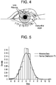
- the first acceptable image of each session was analyzed. Images were considered acceptable if both canthi were within the frame, the image was in focus and exposed well enough that lens fiducials and canthi were visible, and the eye was fixated toward the camera. Images were analyzed to determine the angle of lens rotation ⁇ , defined as the angle of the 0 and 180 degree - sign fiducials relative to the intercanthal angle as illustrated in Figure 4 .
- SD standard deviation
- Rotational stability is likely to be dependent on the activities or tasks that the wearer is performing and the physiological state of the eye.
- one lens may be utilized as a benchmark to compare one lens against another. More specifically, images of a first contact lens may be analyzed to determine the angle of the first contact lens with the visible fiducial marking relative to a reference line connecting, for example, the nasal and temporal canthi to calculate and characterize the distribution of contact lens rotation data over a predetermined or extended time period. This distribution of the first contact lens may be utilized as the benchmark. The process may be repeated with a second contact lens and the results compared to the benchmark.
- the eyelid stabilized design used in the study lenses demonstrated good rotational stability throughout a six (6) hour wear period.
Landscapes
- Health & Medical Sciences (AREA)
- Physics & Mathematics (AREA)
- Ophthalmology & Optometry (AREA)
- Life Sciences & Earth Sciences (AREA)
- General Health & Medical Sciences (AREA)
- General Physics & Mathematics (AREA)
- Optics & Photonics (AREA)
- Engineering & Computer Science (AREA)
- Animal Behavior & Ethology (AREA)
- Medical Informatics (AREA)
- Molecular Biology (AREA)
- Surgery (AREA)
- Heart & Thoracic Surgery (AREA)
- Biomedical Technology (AREA)
- Public Health (AREA)
- Veterinary Medicine (AREA)
- Biophysics (AREA)
- Signal Processing (AREA)
- Multimedia (AREA)
- Chemical & Material Sciences (AREA)
- Analytical Chemistry (AREA)
- Eyeglasses (AREA)
- Grinding And Polishing Of Tertiary Curved Surfaces And Surfaces With Complex Shapes (AREA)
- Testing Of Optical Devices Or Fibers (AREA)
- Length Measuring Devices By Optical Means (AREA)
Abstract
Description
- This patent application claims the benefit of United States Provisional Application No.
62/565437 filed September 29, 2017 - The present invention is directed to a method for evaluating the rotational stability of toric contact lenses on eye, and more particularly to a method enabling contact lens wearers to photograph their own eyes using an electronic device having a camera with a macro lens and a custom three-dimensional printed eyecup attachment.
- Myopia or nearsightedness is an optical or refractive defect of the eye wherein rays of light from an image focus to a point before they reach the retina. Myopia generally occurs because the eyeball or globe is too long or the dome of the cornea is too steep. A minus powered spherical lens may be utilized to correct myopia. Hyperopia or farsightedness is an optical or refractive defect of the eye wherein rays of light from an image focus to a point after they reach or behind the retina. Hyperopia generally occurs because the eyeball or globe is too short or the dome of the cornea is too flat. A plus powered spherical lens may be utilized to correct hyperopia. Astigmatism is an optical or refractive defect in which an individual's vision is blurred due to the inability of the eye to focus a point object into a point image. Astigmatism is caused by an uneven curvature of the cornea or other ocular refracting surfaces whereby the curvature of the refracting surface varies with angular meridian. A non-astigmatic cornea is rotationally symmetrical whereas in an individual with astigmatism, the cornea is not rotationally symmetrical. In other words, the cornea is more curved or steeper in one meridian than another, thereby causing a point object to be focused as two line foci rather than a single point focus. A cylindrical lens rather than a spherical lens may be utilized to resolve astigmatism.
- A toric lens is an optical element having two different powers in two principal meridians that are perpendicular to one another. Each principal meridian of the toric lens corrects the refractive error of the eye within the corresponding plane. The powers of the correcting lens along its principal meridians are created with curvatures of the lens surface that are different at each principal meridian. The orientation of the correcting lens, which may be referred to clinically as the cylinder axis, is preferably maintained relative to the eye for optimal vision correction. Toric lenses may be utilized in eyeglasses, intraocular lenses and contact lenses. The toric lenses used in eyeglasses are held fixed relative to the eye thereby always providing optimal vision correction. However, toric contact lenses may tend to rotate on the eye thereby temporarily providing sub-optimal vision correction. Accordingly, toric contact lenses also include a mechanism to keep the contact lens relatively stable on the eye, including if the wearer blinks or gaze direction changes.
- It is known that correction of certain optical defects may be accomplished by imparting non-rotationally symmetric corrective characteristics to one or more surfaces of a contact lens such as cylindrical, bifocal, multifocal, wavefront corrective characteristics or decentration of the optical zone. It is also known that certain cosmetic features such as print patterns for treating certain medical conditions, for example problems with the iris or portions thereof, markings and/or fiducials, and the like are required to be placed in a specific orientation relative to the wearer's eye. The use of toric contact lenses is problematic in that the lens must be maintained at a specific orientation while on the eye to be effective. When the contact lens is first placed on-eye, it must automatically position, or auto-position, itself and then maintain that position over time. However, once the contact lens is positioned, it's rotational position tends to fluctuate over time due to the force exerted on the contact lens by the eyelids during blinking and changes in the direction of gaze.
- Maintenance of the on-eye orientation of a toric contact lens typically is accomplished by altering the mechanical characteristics of the contact lens. For example, prism stabilization, including tilting of the contact lens' front surface relative to the back surface, thickening of the inferior contact lens periphery, forming depressions or elevations on the contact lens' surface, and truncating the contact lens edge, are all methods that have been utilized to maintain on-eye orientation. Fluctuation in toric contact lens orientation over time directly impacts the quality of vision for astigmatic soft contact lens wearers. Poor vision quality is a key reason for toric lens wearer dropout.
- Previous research suggests smaller palpebral aperture, tighter lens fit, lower myopia, and slower reorientation speed correlate with greater toric lens rotational stability.
- Current clinical test methods for quantifying rotational instability (stability with blinks, stability with eye versions) are generally not well controlled (e.g., number and frequency of blinks, size and angle of versional eye movements) and may not reflect lens stability in 'real world' conditions.
- Accordingly, improved test methods for quantifying toric lens rotational stability under natural wearing conditions would enable more meaningful assessment of lens performance.
- The advantages of the present method and means for evaluating toric contact lens rotational stability overcome the disadvantages associated with current clinical test methods for quantifying rotational stability.
- The present invention is directed to a novel test method and device for tracking lens rotation on eye using self-photography, and to characterize the distribution of the resultant data. More specifically, the present invention is directed to a novel method and means for enabling contact lens wearers to photograph their own eyes using an electronic device with a camera such as an iPhone with a macro lens, for example, Olloclip® Macro Pro Lens Set 7x lens, and a custom three-dimensional printed eyecup attachment. The eyecup attachment is designed to position the camera at a suitable and reproducible distance from the eye to ensure that the system can focus appropriately on the lens details. The eyecup attachment also serves to block stray light and diffuse the ambient lighting. In addition, the eyecup attachment ensures that the camera is held in the correct orientation while photos are being captured.
- The method and means for evaluating toric contact lens rotational stability provides an easy to utilize and inexpensive way of ensuring desired rotational stability of contact lenses. With this device, there is no need for the patient to travel to the eye care professional. In addition, highly accurate results may be achieved.
- The foregoing and other features and advantages of the invention will be apparent from the following, more particular description of preferred embodiments of the invention, as illustrated in the accompanying drawings.
-
Figure 1 is a diagrammatic representation of an exemplary electronic device having a camera, a macro lens and eyecup attachment in accordance with the present invention. -
Figure 2 is a diagrammatic representation of an exemplary contact lens with a fiducial marking scheme in accordance with the present invention. -
Figure 3 is an image of the exemplary contact lens with a fiducial marking scheme on eye taken with an exemplary electronic device having a camera, a macro lens and eyecup attachment in accordance with the present invention. -
Figure 4 is an image of the exemplary contact lens with a fiducial marking scheme on eye illustrating the calculation of lens angle relative to a reference line in accordance with the present invention. -
Figure 5 illustrates the distribution of relative lens rotation over the course of a sample evaluation in accordance with the present invention. -
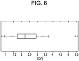
Figure 6 illustrates a boxplot of standard deviation of lens rotation data by eye in accordance with the present invention. - Contact lenses or contacts are simply lenses placed on the eye. Contact lenses are considered medical devices and may be worn to correct vision and/or for cosmetic or other therapeutic reasons. Contact lenses have been utilized commercially to improve vision since the 1950s. Early contact lenses were made or fabricated from hard materials, were relatively expensive and fragile. In addition, these early contact lenses were fabricated from materials that did not allow sufficient oxygen transmission through the contact lens to the conjunctiva and cornea which potentially could cause a number of adverse clinical effects. Although these contact lenses are still utilized, they are not suitable for all patients due to their poor initial comfort. Later developments in the field gave rise to soft contact lenses, based upon hydrogels, which are extremely popular and widely utilized today. Specifically, silicone hydrogel contact lenses that are available today combine the benefit of silicone, which has extremely high oxygen permeability, with the proven comfort and clinical performance of hydrogels. Essentially, these silicone hydrogel based contact lenses have higher oxygen permeabilities and are generally more comfortable to wear than the contact lenses made of the earlier hard materials. The design of the contact lenses and the material choice of silicone hydrogel result in a very comfortable interaction of the lenses to that of the wearer's eyelids.
- Currently available contact lenses remain a cost-effective means for vision correction. The thin plastic lenses fit over the cornea of the eye to correct vision defects, including myopia or nearsightedness, hyperopia or farsightedness, astigmatism, and presbyopia i.e. the loss of the ability of the crystalline lens to accommodate. Contact lenses are available in a variety of forms and are made of a variety of materials to provide different functionality. Soft contact lenses are typically made from soft polymer materials combined with water. Daily wear soft contact lenses may be daily disposable, reusable or extended wear. Daily disposable contact lenses are usually worn for a single day and then thrown away, reusable disposable lenses are usually reworn over multiple days, and extended wear disposable contact lenses are usually worn for a period of up to thirty days. Colored soft contact lenses use different materials to provide different functionality. For example, a visibility tint contact lens uses a light tint to aid the wearer in locating a dropped contact lens, enhancement tint contact lenses have a translucent tint that is meant to enhance one's natural eye color, the color tint contact lens comprises a darker, opaque tint meant to change one's eye color, and the light filtering tint contact lens functions to enhance certain colors while muting others. Rigid gas permeable hard contact lenses are made from siloxane-containing polymers but are more rigid than soft contact lenses and thus hold their shape and are more durable. Bifocal contact lenses are designed specifically for patients with presbyopia and are available in both soft and rigid varieties. Toric contact lenses are designed specifically for patients with astigmatism and are also available in both soft and rigid varieties. Combination lenses combining different aspects of the above are also available, for example, hybrid contact lenses.
- In accordance with the present invention, a study was designed to evaluate a novel test method for tracking lens rotation using self-photography, and to characterize the distribution of the resultant data. The results of the study demonstrate that it is feasible to quantify the stability of a toric contact lens under real-world conditions. It is important to note that in addition to rotational stability; lens movement may be investigated during various activities or eye movements and/or to quantitatively compare the performance of alternate contact lens designs. The study utilized the same system and methodology that is to be utilized by patients and eye care professionals. A detailed description of the study is given subsequent to a detailed description of the system.
- As set forth above, the present invention is directed to a method and means for enabling contact lens wearers to photograph their own eyes using a hand-held electronic device having a camera, a macro lens, and an eyecup attachment.
Figure 1 illustrates thesystem 100 comprising theelectronic device 102, themacro lens 104 and theeyecup attachment 106. - The hand-held
electronic device 102 comprising a camera may be any suitable device currently available for capturing images with sufficient resolution as set forth below. Examples of hand-held electronic devices with cameras include phones, smart phones, for example, iPhones, tablet computing devices, for example, iPads, high definition webcam, as well as digital cameras and video cameras with wireless and/or Bluetooth connectivity, all with at least a camera option for capturing still images and or video. In an exemplary embodiment in accordance with the present invention, the hand-heldelectronic device 102 comprises an iPhone, and more specifically aniPhone 6 Plus, although in alternative exemplary embodiments, other smartphone brands and mobile devices may be utilized as set forth above. - A macro lens, in its most general terms, is an optical device that is able to reproduce a life-sized image of an object on a recording medium. True macro lenses provide a magnification factor of 1.0x or 1:1 at its closest focus setting. Essentially, macro lenses can provide massive enlargements of small objects. Any suitable
macro lens 104 may be utilized with the present invention and is preferably easy to connect to the camera and is lightweight. In the present invention, a Olloclip® Macro Pro LensSet 7x lens 104 is utilized with theiPhone 6Plus 102. This macro lens essentially converts the iPhone into a digital microscope or loupe with edge-to-edge clarity. The Olloclip® Macro Pro LensSet 7x lens 104 comes with all the necessary components for attachment to theiPhone 102. - The eyecup attachment or
eyepiece 106 is designed to position the camera of theelectronic device 102 at a suitable distance from the user's eye to ensure that the camera can focus appropriately on the lens details, block stray light and diffuse ambient light and ensure that the camera is held in correct orientation while images are captured. Each image should preferably be from the same vantage point and thus theeyepiece 106 is required to maintain distance and orientation. Theeyepiece 106 comprises a wing shapedelement 108 that facilitates correct orientation by the user. Theeyepiece 106 is preferably manufactured from a lightweight material, for example, a polymer or lightweight metal such as aluminum and may be manufactured by any type of process, including, machining, injection molding and various forms of three-dimensional printing processes. In the exemplary embodiment in accordance with the present invention, theeyepiece 106 is manufactured from a plastic material utilizing a three-dimensional printing process and smoothed sufficiently for placement in contact with the sensitive skin surrounding the eye. In other words, theeyepiece 106 should preferably promote a favorable tactile response. In the exemplary embodiment, theeyepiece 106 has a threaded section for attachment to thelens 104; however, any suitable attachment means may be utilized. - A contact lens with fiducial markings is photographed using the
system 100 illustrated inFigure 1 . A detailed description of the contact lens and process is given below in the description of the study. Current clinical methods of measuring toric soft contact lens rotational stability are short in duration, subject to variability and may not reflect real-world performance. The study set forth below investigated the feasibility of a method for quantifying the stability of a toric contact lens under real-world conditions via self-photography. The study's contact lens parameters are given in Table 1 below.Table 1 Specification Parameter Material Senofilcon A Water content (%) 38 Base curve (mm) 8.6 Diameter (mm) 14.3 Lens power (D) 0.00 (plano) Stabilization design Blink Stabilized Design (BSD) - Study lenses featured the same stabilization design used in ACUVUE OASYS® 1-Day for ASTIGMATISM brand contact lenses available from Johnson & Johnson Vision Care and were manufactured with a white fiducial print pattern as illustrated in
Figure 2 . Thestudy contact lens 200 comprises two + sign fiducials positioned at 90 and 270 degrees and two - sign fiducials positioned at 0 and 180 degrees. An example image of the study contact lens design captured using thesystem 100 ofFigure 1 is illustrated inFigure 3 . As may be readily seen, three out of four of the fiducials are clearly seen. - Twelve (12) healthy habitual soft contact lens wearers, twenty-four (24) eyes, between nineteen (19) and thirty-five (35) years of age were enrolled in the study. Subjects were given detailed training and instructions for capturing images in primary position and to review each image immediately following capture to ensure acceptable quality. A timing app 'Timer+' was used to sound an alarm at thirty (30) minute intervals to signal a new capture session. That is, every thirty (30) minutes, an alarm sounded to remind the patient to collect images of both eyes using the device. Subjects wore lenses bilaterally and were instructed to capture a minimum of two (2) images per eye, per capture session over a wear period of at least six (6) hours using the
system 100 ofFigure 1 . Following completion of the wear period, images were transferred from the iPhone to a computer using a standard USB connector. Images were then analyzed by a trained investigator using custom image processing software application written in MATLAB (The MathWorks, Inc). For each photograph, the image processing software was used to identify the position of certain features within that photograph, including the horizontal lens fiducials (depicted by a - sign) and the ocular canthi. The software used the identified location of these features to calculate the angle of the fiducials with respect to the intercanthal angle. - For each eye, the first acceptable image of each session was analyzed. Images were considered acceptable if both canthi were within the frame, the image was in focus and exposed well enough that lens fiducials and canthi were visible, and the eye was fixated toward the camera. Images were analyzed to determine the angle of lens rotation θ, defined as the angle of the 0 and 180 degree - sign fiducials relative to the intercanthal angle as illustrated in
Figure 4 . - An exploratory analysis was conducted to characterize the distribution of relative lens rotation data. Both eyes of one subject were excluded from the analysis due to poor quality photographs (under-exposure, poor focus, variable fixation). In total, two-hundred seventy-three (273) images from eleven (11) subjects or twenty-two (22) eyes were analyzed. Subject demographics are summarized in Table 2 below.
Table 2 Gender Male 7 Female 4 Race Asian 4 African American 1 White 6 Age (Mean ± SD) 26.5 ± 4.6 Mean spherical refraction (Mean ± SD) -3.2 ± 1.1 - For each eye, the total number of capture sessions range from eleven (11) to fourteen (14) with a median of twelve (12). A histogram of relative lens rotation data for all eyes combined suggested that these data are normally distributed, as illustrated in
Figure 5 . - For each eye, the variability in lens orientation over time was quantified by calculating the standard deviation (SD) of lens rotation data points for that eye. A boxplot of SDs for all eyes included in the analysis is illustrated in
Figure 6 . This SD ranged from 0.9 degrees to 5.4 degrees, with a mean standard deviation of 2.4 degree (median 2.2 degrees). - The successful acquisition and analysis of photographs in this study supports the feasibility of this novel test method for evaluating toric lens rotational stability. In addition, the data suggests that the fluctuation in toric lens orientation for this design follows a normal distribution. Given the mean standard deviation of 2.4 degrees, it can be inferred that, for an average eye wearing the toric design used in this study, ninety-five (95) percent of the time the lens was within approximately ±5 degrees (2 x SD) of its mean rotational position.
- Rotational stability is likely to be dependent on the activities or tasks that the wearer is performing and the physiological state of the eye.
- It is important to note that one lens may be utilized as a benchmark to compare one lens against another. More specifically, images of a first contact lens may be analyzed to determine the angle of the first contact lens with the visible fiducial marking relative to a reference line connecting, for example, the nasal and temporal canthi to calculate and characterize the distribution of contact lens rotation data over a predetermined or extended time period. This distribution of the first contact lens may be utilized as the benchmark. The process may be repeated with a second contact lens and the results compared to the benchmark.
- A potential limitation associated with this study was that it measured lens orientation relative to intercanthal angle which does not account for cyclotorsion of the globe; this could be addressed in future studies by using more sophisticated image analysis using, for example, conjunctival blood vessels or iris features as landmarks. In addition, future investigations could use this method to investigate toric lens stability during different activities or to compare the relative stability of alternative stabilization designs.
- Results of this study; however, support the feasibility of using a device with a digital camera with a macro lens and eyecup with custom printed toric lenses to evaluate toric lens stability during natural wear conditions.
- The eyelid stabilized design used in the study lenses demonstrated good rotational stability throughout a six (6) hour wear period.
- Although shown and described in what is believed to be the most practical and preferred embodiments, it is apparent that departures from specific designs and methods described and shown will suggest themselves to those skilled in the art and may be used without departing from the spirit and scope of the invention. The present invention is not restricted to the particular constructions described and illustrated, but should be constructed to cohere with all modifications that may fall within the scope of the appended claims.
Claims (3)
- A method for evaluating toric contact lens rotational stability on-eye, the method comprising the steps of:providing lens wearers with an electronic device including a camera having a macro lens and eyecup attachment and at least a first contact lens with visible fiducial markers;instructing lens wearers to photograph each eye while wearing their contact lens at fixed time intervals over an extended time period using the electronic device; andanalyzing photographs of the contact lens on-eye using image processing software to determine the angle of the first contact lens with visible fiducial markers relative to a reference line connecting the nasal and temporal canthi to calculate and characterize the distribution of contact lens rotation data over the extended time period.
- The method of Claim 1 further comprising the steps of:using the calculated and characterized distribution of contact lens rotation data over the extended time period as a reference benchmark;providing lens wearers with an electronic device including a camera having a macro lens and eyecup attachment and a second contact lens different from the first contact lens, the second contact lens including visible fiducial markers;instructing lens wearers to photograph each eye while wearing the second contact lens at fixed time intervals over an extended time period using the electronic device;analyzing photographs using image processing software to determine the angle of the second contact lens with visible fiducial markers relative to a reference line connecting the nasal and temporal canthi to calculate and characterize the distribution of contact lens rotation data over the extended time period; and comparing the calculated and characterized contact lens rotation data of the second contact lens with that of the first contact lens which serves as a reference benchmark.
- A system for evaluating toric contact lens rotational stability on-eye, the system comprising:a hand-held electronic device including a camera;a macro lens configured for attachment to the hand-held electronic device;an eyepiece attached to the hand-held electronic device, the eyepiece being configured to orient the camera of the hand-held electronic device at a fixed position from an eye of a contact lens wearer; anda contact lens comprising fiducial markings that are capturable in an image, wherein the images are analyzed using image processing software to determine the angle of the contact lens with fiducial markers relative to a reference line connecting the nasal and temporal canthi to calculate and characterize the distribution of contact lens rotation data over an extended time period.
Applications Claiming Priority (2)
| Application Number | Priority Date | Filing Date | Title |
|---|---|---|---|
| US201762565437P | 2017-09-29 | 2017-09-29 | |
| US15/851,843 US11509755B2 (en) | 2017-09-29 | 2017-12-22 | Method and means for evaluating toric contact lens rotational stability |
Publications (2)
| Publication Number | Publication Date |
|---|---|
| EP3462231A1 true EP3462231A1 (en) | 2019-04-03 |
| EP3462231B1 EP3462231B1 (en) | 2024-04-17 |
Family
ID=63713710
Family Applications (1)
| Application Number | Title | Priority Date | Filing Date |
|---|---|---|---|
| EP18197705.9A Active EP3462231B1 (en) | 2017-09-29 | 2018-09-28 | A method and means for evaluating toric contact lens rotational stability |
Country Status (5)
| Country | Link |
|---|---|
| US (1) | US11509755B2 (en) |
| EP (1) | EP3462231B1 (en) |
| JP (1) | JP7305325B2 (en) |
| KR (1) | KR102710119B1 (en) |
| CN (1) | CN109580176B (en) |
Families Citing this family (4)
| Publication number | Priority date | Publication date | Assignee | Title |
|---|---|---|---|---|
| BR112019010513A2 (en) * | 2016-11-29 | 2019-09-17 | Y Soft Scanning Solutions s.r.o. | system for distributing image scan tasks to networked devices |
| US12369794B2 (en) * | 2020-08-10 | 2025-07-29 | Welch Allyn, Inc. | Microvascular assessment using eye imaging device |
| US12622585B2 (en) | 2022-09-19 | 2026-05-12 | Pes Innovations, Llc | Ophthalmic system for imaging the interior of an eye |
| US12191038B2 (en) | 2022-09-19 | 2025-01-07 | Alan Andrew Norman | Method for analyzing a retinal image of an eye |
Citations (6)
| Publication number | Priority date | Publication date | Assignee | Title |
|---|---|---|---|---|
| WO2005015290A2 (en) * | 2003-07-24 | 2005-02-17 | Technovision Gmbh Gesellschaft Für Die Entwicklung Medizinischer Technologien | Method and apparatus for online contact lens evaluation |
| WO2006135561A1 (en) * | 2005-06-08 | 2006-12-21 | Johnson & Johnson Vision Care, Inc. | Method for evaluating eyelid movement and contact lens position |
| CA2717328A1 (en) * | 2010-10-14 | 2012-04-14 | Anton Sabeta | Method and system for determining the orientation of an ophthalmic lens |
| WO2016156810A1 (en) * | 2015-04-02 | 2016-10-06 | Coopervision International Holding Company, Lp | Systems and methods for determining an angle of repose of an asymmetric lens |
| WO2016179370A1 (en) * | 2015-05-05 | 2016-11-10 | The Arizona Board Of Regents On Behalf Of The University Of Arizona | Smartphone-based handheld ophthalmic examination devices |
| US20170119250A1 (en) * | 2015-11-04 | 2017-05-04 | The Charles Stark Draper Laboratory, Inc. | Portable hardware fixture for fundoscopy |
Family Cites Families (12)
| Publication number | Priority date | Publication date | Assignee | Title |
|---|---|---|---|---|
| JP2003126040A (en) | 2001-10-19 | 2003-05-07 | Menicon Co Ltd | Contact lens suitability evaluation apparatus and suitability evaluation method |
| US20090033864A1 (en) | 2007-07-30 | 2009-02-05 | Shone Thomas R | Multifocal contact lenses and methods for improving vision and for producing multifocal contact lenses |
| US8636357B2 (en) | 2009-07-31 | 2014-01-28 | Johnson & Johnson Vision Care, Inc. | Custom contact lenses with fiducial markings |
| US8439499B2 (en) | 2009-12-17 | 2013-05-14 | Johnson & Johnson Vision Care, Inc. | Method for producing stabilized contact lenses |
| JP2013070941A (en) | 2011-09-29 | 2013-04-22 | Nidek Co Ltd | Ophthalmologic photographing apparatus |
| JP6005488B2 (en) | 2012-11-26 | 2016-10-12 | 株式会社クリュートメディカルシステムズ | Ophthalmic observation system |
| KR101702558B1 (en) * | 2014-04-23 | 2017-02-13 | 주식회사 한국존슨앤드존슨 | Device for measuring off-axis of astigmatic lens and method thereof |
| JP6355438B2 (en) * | 2014-06-05 | 2018-07-11 | キヤノン株式会社 | Ophthalmic measuring apparatus, control method thereof, and program |
| US10739617B2 (en) | 2015-06-12 | 2020-08-11 | Johnson & Johnson Vision Care, Inc. | Comfort-optimized contact lens system for non-rotationally symmetric eye aberration |
| US9778487B2 (en) * | 2015-08-26 | 2017-10-03 | Johnson & Johnson Vision Care, Inc. | Rotationally stabilized contact lens with improved comfort and method of optimization |
| US10788683B2 (en) * | 2015-10-12 | 2020-09-29 | Rude Loren | Method and system of creating an optimized lens for an eye |
| CN105974611B (en) * | 2016-07-27 | 2019-01-29 | 东南大学 | The multi-functional detection contact lenses of one kind and its preparation and inspection method |
-
2017
- 2017-12-22 US US15/851,843 patent/US11509755B2/en active Active
-
2018
- 2018-09-28 JP JP2018183339A patent/JP7305325B2/en active Active
- 2018-09-28 KR KR1020180115610A patent/KR102710119B1/en active Active
- 2018-09-28 EP EP18197705.9A patent/EP3462231B1/en active Active
- 2018-09-28 CN CN201811144766.1A patent/CN109580176B/en active Active
Patent Citations (6)
| Publication number | Priority date | Publication date | Assignee | Title |
|---|---|---|---|---|
| WO2005015290A2 (en) * | 2003-07-24 | 2005-02-17 | Technovision Gmbh Gesellschaft Für Die Entwicklung Medizinischer Technologien | Method and apparatus for online contact lens evaluation |
| WO2006135561A1 (en) * | 2005-06-08 | 2006-12-21 | Johnson & Johnson Vision Care, Inc. | Method for evaluating eyelid movement and contact lens position |
| CA2717328A1 (en) * | 2010-10-14 | 2012-04-14 | Anton Sabeta | Method and system for determining the orientation of an ophthalmic lens |
| WO2016156810A1 (en) * | 2015-04-02 | 2016-10-06 | Coopervision International Holding Company, Lp | Systems and methods for determining an angle of repose of an asymmetric lens |
| WO2016179370A1 (en) * | 2015-05-05 | 2016-11-10 | The Arizona Board Of Regents On Behalf Of The University Of Arizona | Smartphone-based handheld ophthalmic examination devices |
| US20170119250A1 (en) * | 2015-11-04 | 2017-05-04 | The Charles Stark Draper Laboratory, Inc. | Portable hardware fixture for fundoscopy |
Also Published As
| Publication number | Publication date |
|---|---|
| KR102710119B1 (en) | 2024-09-27 |
| KR20190038406A (en) | 2019-04-08 |
| JP2019066846A (en) | 2019-04-25 |
| CN109580176B (en) | 2023-07-18 |
| US20190104210A1 (en) | 2019-04-04 |
| RU2018134179A3 (en) | 2021-11-08 |
| RU2018134179A (en) | 2020-04-01 |
| CN109580176A (en) | 2019-04-05 |
| EP3462231B1 (en) | 2024-04-17 |
| US11509755B2 (en) | 2022-11-22 |
| JP7305325B2 (en) | 2023-07-10 |
Similar Documents
| Publication | Publication Date | Title |
|---|---|---|
| US11497931B2 (en) | Lens with asymmetric projection to treat astigmatism | |
| EP3649577B1 (en) | Application to determine reading/working distance | |
| KR102021750B1 (en) | Multi-axis lens design for astigmatism | |
| AU2010276507B2 (en) | Custom contact lenses with fiducial markings | |
| WO2021252318A1 (en) | Lens with asymmetric projection to treat astigmatism | |
| US20130297015A1 (en) | Customized wavefront-guided methods, systems, and devices to correct higher-order aberrations | |
| KR102710119B1 (en) | A method and means for evaluating toric contact lens rotational stability | |
| KR20150036147A (en) | Device and method for measuring objective ocular refraction and at least one geometric-morphological parameter of an individual | |
| WO2021056059A9 (en) | A freeform contact lens solution for myopia | |
| KR20140053793A (en) | Contact lens with improved fitting characteristics | |
| CN116507301B (en) | Systems and methods for determining the appropriate timing to modify or change an initial myopia control program. | |
| RU2774315C2 (en) | Method and device for assessment of rotational stability of toric contact lenses | |
| HK40006043A (en) | A method and means for evaluating toric contact lens rotational stability | |
| ES2929214T3 (en) | Apparatus and method for customizing an optical lens | |
| HK40006043B (en) | A method and means for evaluating toric contact lens rotational stability | |
| WO2023064792A1 (en) | Adaptive system for the treatment of myopia progression | |
| GB2288033A (en) | Contact lens having central aspherical and annular spherical lens | |
| AU2016225918B2 (en) | Multi-axis lens design for astigmatism | |
| EP4105713B1 (en) | Eyewear for a subject having an eye provided with a myopia control solution and associated method | |
| Maheshwari et al. | Learning optics using vision | |
| HK40029694B (en) | Application to determine reading/working distance | |
| HK40029694A (en) | Application to determine reading/working distance | |
| Orbeck et al. | Rigid gas-permeable fitting system | |
| Johnson et al. | Patient brochure on contact lens options | |
| HK1221628B (en) | Method and system for determining the refractive properties of an eye of a child |
Legal Events
| Date | Code | Title | Description |
|---|---|---|---|
| PUAI | Public reference made under article 153(3) epc to a published international application that has entered the european phase |
Free format text: ORIGINAL CODE: 0009012 |
|
| STAA | Information on the status of an ep patent application or granted ep patent |
Free format text: STATUS: THE APPLICATION HAS BEEN PUBLISHED |
|
| AK | Designated contracting states |
Kind code of ref document: A1 Designated state(s): AL AT BE BG CH CY CZ DE DK EE ES FI FR GB GR HR HU IE IS IT LI LT LU LV MC MK MT NL NO PL PT RO RS SE SI SK SM TR |
|
| AX | Request for extension of the european patent |
Extension state: BA ME |
|
| STAA | Information on the status of an ep patent application or granted ep patent |
Free format text: STATUS: REQUEST FOR EXAMINATION WAS MADE |
|
| 17P | Request for examination filed |
Effective date: 20191002 |
|
| RBV | Designated contracting states (corrected) |
Designated state(s): AL AT BE BG CH CY CZ DE DK EE ES FI FR GB GR HR HU IE IS IT LI LT LU LV MC MK MT NL NO PL PT RO RS SE SI SK SM TR |
|
| REG | Reference to a national code |
Ref country code: HK Ref legal event code: DE Ref document number: 40006043 Country of ref document: HK |
|
| STAA | Information on the status of an ep patent application or granted ep patent |
Free format text: STATUS: EXAMINATION IS IN PROGRESS |
|
| 17Q | First examination report despatched |
Effective date: 20220412 |
|
| GRAP | Despatch of communication of intention to grant a patent |
Free format text: ORIGINAL CODE: EPIDOSNIGR1 |
|
| STAA | Information on the status of an ep patent application or granted ep patent |
Free format text: STATUS: GRANT OF PATENT IS INTENDED |
|
| INTG | Intention to grant announced |
Effective date: 20231117 |
|
| GRAS | Grant fee paid |
Free format text: ORIGINAL CODE: EPIDOSNIGR3 |
|
| GRAA | (expected) grant |
Free format text: ORIGINAL CODE: 0009210 |
|
| STAA | Information on the status of an ep patent application or granted ep patent |
Free format text: STATUS: THE PATENT HAS BEEN GRANTED |
|
| AK | Designated contracting states |
Kind code of ref document: B1 Designated state(s): AL AT BE BG CH CY CZ DE DK EE ES FI FR GB GR HR HU IE IS IT LI LT LU LV MC MK MT NL NO PL PT RO RS SE SI SK SM TR |
|
| REG | Reference to a national code |
Ref country code: GB Ref legal event code: FG4D |
|
| REG | Reference to a national code |
Ref country code: CH Ref legal event code: EP |
|
| REG | Reference to a national code |
Ref country code: DE Ref legal event code: R096 Ref document number: 602018068114 Country of ref document: DE |
|
| REG | Reference to a national code |
Ref country code: IE Ref legal event code: FG4D |
|
| REG | Reference to a national code |
Ref country code: LT Ref legal event code: MG9D |
|
| REG | Reference to a national code |
Ref country code: NL Ref legal event code: MP Effective date: 20240417 |
|
| REG | Reference to a national code |
Ref country code: AT Ref legal event code: MK05 Ref document number: 1677798 Country of ref document: AT Kind code of ref document: T Effective date: 20240417 |
|
| PG25 | Lapsed in a contracting state [announced via postgrant information from national office to epo] |
Ref country code: NL Free format text: LAPSE BECAUSE OF FAILURE TO SUBMIT A TRANSLATION OF THE DESCRIPTION OR TO PAY THE FEE WITHIN THE PRESCRIBED TIME-LIMIT Effective date: 20240417 |
|
| PG25 | Lapsed in a contracting state [announced via postgrant information from national office to epo] |
Ref country code: NL Free format text: LAPSE BECAUSE OF FAILURE TO SUBMIT A TRANSLATION OF THE DESCRIPTION OR TO PAY THE FEE WITHIN THE PRESCRIBED TIME-LIMIT Effective date: 20240417 |
|
| PG25 | Lapsed in a contracting state [announced via postgrant information from national office to epo] |
Ref country code: IS Free format text: LAPSE BECAUSE OF FAILURE TO SUBMIT A TRANSLATION OF THE DESCRIPTION OR TO PAY THE FEE WITHIN THE PRESCRIBED TIME-LIMIT Effective date: 20240817 |
|
| PG25 | Lapsed in a contracting state [announced via postgrant information from national office to epo] |
Ref country code: BG Free format text: LAPSE BECAUSE OF FAILURE TO SUBMIT A TRANSLATION OF THE DESCRIPTION OR TO PAY THE FEE WITHIN THE PRESCRIBED TIME-LIMIT Effective date: 20240417 |
|
| PG25 | Lapsed in a contracting state [announced via postgrant information from national office to epo] |
Ref country code: HR Free format text: LAPSE BECAUSE OF FAILURE TO SUBMIT A TRANSLATION OF THE DESCRIPTION OR TO PAY THE FEE WITHIN THE PRESCRIBED TIME-LIMIT Effective date: 20240417 Ref country code: FI Free format text: LAPSE BECAUSE OF FAILURE TO SUBMIT A TRANSLATION OF THE DESCRIPTION OR TO PAY THE FEE WITHIN THE PRESCRIBED TIME-LIMIT Effective date: 20240417 |
|
| PG25 | Lapsed in a contracting state [announced via postgrant information from national office to epo] |
Ref country code: GR Free format text: LAPSE BECAUSE OF FAILURE TO SUBMIT A TRANSLATION OF THE DESCRIPTION OR TO PAY THE FEE WITHIN THE PRESCRIBED TIME-LIMIT Effective date: 20240718 |
|
| PG25 | Lapsed in a contracting state [announced via postgrant information from national office to epo] |
Ref country code: PT Free format text: LAPSE BECAUSE OF FAILURE TO SUBMIT A TRANSLATION OF THE DESCRIPTION OR TO PAY THE FEE WITHIN THE PRESCRIBED TIME-LIMIT Effective date: 20240819 |
|
| PG25 | Lapsed in a contracting state [announced via postgrant information from national office to epo] |
Ref country code: ES Free format text: LAPSE BECAUSE OF FAILURE TO SUBMIT A TRANSLATION OF THE DESCRIPTION OR TO PAY THE FEE WITHIN THE PRESCRIBED TIME-LIMIT Effective date: 20240417 |
|
| PG25 | Lapsed in a contracting state [announced via postgrant information from national office to epo] |
Ref country code: AT Free format text: LAPSE BECAUSE OF FAILURE TO SUBMIT A TRANSLATION OF THE DESCRIPTION OR TO PAY THE FEE WITHIN THE PRESCRIBED TIME-LIMIT Effective date: 20240417 |
|
| PG25 | Lapsed in a contracting state [announced via postgrant information from national office to epo] |
Ref country code: PL Free format text: LAPSE BECAUSE OF FAILURE TO SUBMIT A TRANSLATION OF THE DESCRIPTION OR TO PAY THE FEE WITHIN THE PRESCRIBED TIME-LIMIT Effective date: 20240417 |
|
| PG25 | Lapsed in a contracting state [announced via postgrant information from national office to epo] |
Ref country code: LV Free format text: LAPSE BECAUSE OF FAILURE TO SUBMIT A TRANSLATION OF THE DESCRIPTION OR TO PAY THE FEE WITHIN THE PRESCRIBED TIME-LIMIT Effective date: 20240417 |
|
| PG25 | Lapsed in a contracting state [announced via postgrant information from national office to epo] |
Ref country code: PT Free format text: LAPSE BECAUSE OF FAILURE TO SUBMIT A TRANSLATION OF THE DESCRIPTION OR TO PAY THE FEE WITHIN THE PRESCRIBED TIME-LIMIT Effective date: 20240819 Ref country code: PL Free format text: LAPSE BECAUSE OF FAILURE TO SUBMIT A TRANSLATION OF THE DESCRIPTION OR TO PAY THE FEE WITHIN THE PRESCRIBED TIME-LIMIT Effective date: 20240417 Ref country code: NO Free format text: LAPSE BECAUSE OF FAILURE TO SUBMIT A TRANSLATION OF THE DESCRIPTION OR TO PAY THE FEE WITHIN THE PRESCRIBED TIME-LIMIT Effective date: 20240717 Ref country code: LV Free format text: LAPSE BECAUSE OF FAILURE TO SUBMIT A TRANSLATION OF THE DESCRIPTION OR TO PAY THE FEE WITHIN THE PRESCRIBED TIME-LIMIT Effective date: 20240417 Ref country code: IS Free format text: LAPSE BECAUSE OF FAILURE TO SUBMIT A TRANSLATION OF THE DESCRIPTION OR TO PAY THE FEE WITHIN THE PRESCRIBED TIME-LIMIT Effective date: 20240817 Ref country code: HR Free format text: LAPSE BECAUSE OF FAILURE TO SUBMIT A TRANSLATION OF THE DESCRIPTION OR TO PAY THE FEE WITHIN THE PRESCRIBED TIME-LIMIT Effective date: 20240417 Ref country code: GR Free format text: LAPSE BECAUSE OF FAILURE TO SUBMIT A TRANSLATION OF THE DESCRIPTION OR TO PAY THE FEE WITHIN THE PRESCRIBED TIME-LIMIT Effective date: 20240718 Ref country code: FI Free format text: LAPSE BECAUSE OF FAILURE TO SUBMIT A TRANSLATION OF THE DESCRIPTION OR TO PAY THE FEE WITHIN THE PRESCRIBED TIME-LIMIT Effective date: 20240417 Ref country code: ES Free format text: LAPSE BECAUSE OF FAILURE TO SUBMIT A TRANSLATION OF THE DESCRIPTION OR TO PAY THE FEE WITHIN THE PRESCRIBED TIME-LIMIT Effective date: 20240417 Ref country code: BG Free format text: LAPSE BECAUSE OF FAILURE TO SUBMIT A TRANSLATION OF THE DESCRIPTION OR TO PAY THE FEE WITHIN THE PRESCRIBED TIME-LIMIT Effective date: 20240417 Ref country code: AT Free format text: LAPSE BECAUSE OF FAILURE TO SUBMIT A TRANSLATION OF THE DESCRIPTION OR TO PAY THE FEE WITHIN THE PRESCRIBED TIME-LIMIT Effective date: 20240417 Ref country code: RS Free format text: LAPSE BECAUSE OF FAILURE TO SUBMIT A TRANSLATION OF THE DESCRIPTION OR TO PAY THE FEE WITHIN THE PRESCRIBED TIME-LIMIT Effective date: 20240717 |
|
| PG25 | Lapsed in a contracting state [announced via postgrant information from national office to epo] |
Ref country code: DK Free format text: LAPSE BECAUSE OF FAILURE TO SUBMIT A TRANSLATION OF THE DESCRIPTION OR TO PAY THE FEE WITHIN THE PRESCRIBED TIME-LIMIT Effective date: 20240417 |
|
| REG | Reference to a national code |
Ref country code: DE Ref legal event code: R097 Ref document number: 602018068114 Country of ref document: DE |
|
| PG25 | Lapsed in a contracting state [announced via postgrant information from national office to epo] |
Ref country code: EE Free format text: LAPSE BECAUSE OF FAILURE TO SUBMIT A TRANSLATION OF THE DESCRIPTION OR TO PAY THE FEE WITHIN THE PRESCRIBED TIME-LIMIT Effective date: 20240417 |
|
| PG25 | Lapsed in a contracting state [announced via postgrant information from national office to epo] |
Ref country code: CZ Free format text: LAPSE BECAUSE OF FAILURE TO SUBMIT A TRANSLATION OF THE DESCRIPTION OR TO PAY THE FEE WITHIN THE PRESCRIBED TIME-LIMIT Effective date: 20240417 |
|
| PG25 | Lapsed in a contracting state [announced via postgrant information from national office to epo] |
Ref country code: SK Free format text: LAPSE BECAUSE OF FAILURE TO SUBMIT A TRANSLATION OF THE DESCRIPTION OR TO PAY THE FEE WITHIN THE PRESCRIBED TIME-LIMIT Effective date: 20240417 Ref country code: RO Free format text: LAPSE BECAUSE OF FAILURE TO SUBMIT A TRANSLATION OF THE DESCRIPTION OR TO PAY THE FEE WITHIN THE PRESCRIBED TIME-LIMIT Effective date: 20240417 |
|
| PG25 | Lapsed in a contracting state [announced via postgrant information from national office to epo] |
Ref country code: SM Free format text: LAPSE BECAUSE OF FAILURE TO SUBMIT A TRANSLATION OF THE DESCRIPTION OR TO PAY THE FEE WITHIN THE PRESCRIBED TIME-LIMIT Effective date: 20240417 |
|
| PG25 | Lapsed in a contracting state [announced via postgrant information from national office to epo] |
Ref country code: SM Free format text: LAPSE BECAUSE OF FAILURE TO SUBMIT A TRANSLATION OF THE DESCRIPTION OR TO PAY THE FEE WITHIN THE PRESCRIBED TIME-LIMIT Effective date: 20240417 Ref country code: SK Free format text: LAPSE BECAUSE OF FAILURE TO SUBMIT A TRANSLATION OF THE DESCRIPTION OR TO PAY THE FEE WITHIN THE PRESCRIBED TIME-LIMIT Effective date: 20240417 Ref country code: RO Free format text: LAPSE BECAUSE OF FAILURE TO SUBMIT A TRANSLATION OF THE DESCRIPTION OR TO PAY THE FEE WITHIN THE PRESCRIBED TIME-LIMIT Effective date: 20240417 Ref country code: EE Free format text: LAPSE BECAUSE OF FAILURE TO SUBMIT A TRANSLATION OF THE DESCRIPTION OR TO PAY THE FEE WITHIN THE PRESCRIBED TIME-LIMIT Effective date: 20240417 Ref country code: DK Free format text: LAPSE BECAUSE OF FAILURE TO SUBMIT A TRANSLATION OF THE DESCRIPTION OR TO PAY THE FEE WITHIN THE PRESCRIBED TIME-LIMIT Effective date: 20240417 Ref country code: CZ Free format text: LAPSE BECAUSE OF FAILURE TO SUBMIT A TRANSLATION OF THE DESCRIPTION OR TO PAY THE FEE WITHIN THE PRESCRIBED TIME-LIMIT Effective date: 20240417 |
|
| PLBE | No opposition filed within time limit |
Free format text: ORIGINAL CODE: 0009261 |
|
| STAA | Information on the status of an ep patent application or granted ep patent |
Free format text: STATUS: NO OPPOSITION FILED WITHIN TIME LIMIT |
|
| 26N | No opposition filed |
Effective date: 20250120 |
|
| PG25 | Lapsed in a contracting state [announced via postgrant information from national office to epo] |
Ref country code: SI Free format text: LAPSE BECAUSE OF FAILURE TO SUBMIT A TRANSLATION OF THE DESCRIPTION OR TO PAY THE FEE WITHIN THE PRESCRIBED TIME-LIMIT Effective date: 20240417 Ref country code: MC Free format text: LAPSE BECAUSE OF FAILURE TO SUBMIT A TRANSLATION OF THE DESCRIPTION OR TO PAY THE FEE WITHIN THE PRESCRIBED TIME-LIMIT Effective date: 20240417 |
|
| REG | Reference to a national code |
Ref country code: CH Ref legal event code: PL |
|
| PG25 | Lapsed in a contracting state [announced via postgrant information from national office to epo] |
Ref country code: LU Free format text: LAPSE BECAUSE OF NON-PAYMENT OF DUE FEES Effective date: 20240928 |
|
| REG | Reference to a national code |
Ref country code: BE Ref legal event code: MM Effective date: 20240930 |
|
| PG25 | Lapsed in a contracting state [announced via postgrant information from national office to epo] |
Ref country code: BE Free format text: LAPSE BECAUSE OF NON-PAYMENT OF DUE FEES Effective date: 20240930 |
|
| PG25 | Lapsed in a contracting state [announced via postgrant information from national office to epo] |
Ref country code: CH Free format text: LAPSE BECAUSE OF NON-PAYMENT OF DUE FEES Effective date: 20240930 |
|
| PG25 | Lapsed in a contracting state [announced via postgrant information from national office to epo] |
Ref country code: SE Free format text: LAPSE BECAUSE OF FAILURE TO SUBMIT A TRANSLATION OF THE DESCRIPTION OR TO PAY THE FEE WITHIN THE PRESCRIBED TIME-LIMIT Effective date: 20240417 |
|
| PGFP | Annual fee paid to national office [announced via postgrant information from national office to epo] |
Ref country code: DE Payment date: 20250805 Year of fee payment: 8 |
|
| PGFP | Annual fee paid to national office [announced via postgrant information from national office to epo] |
Ref country code: IT Payment date: 20250825 Year of fee payment: 8 |
|
| PGFP | Annual fee paid to national office [announced via postgrant information from national office to epo] |
Ref country code: GB Payment date: 20250807 Year of fee payment: 8 |
|
| PGFP | Annual fee paid to national office [announced via postgrant information from national office to epo] |
Ref country code: FR Payment date: 20250808 Year of fee payment: 8 |
|
| PGFP | Annual fee paid to national office [announced via postgrant information from national office to epo] |
Ref country code: IE Payment date: 20250812 Year of fee payment: 8 |
|
| PG25 | Lapsed in a contracting state [announced via postgrant information from national office to epo] |
Ref country code: CY Free format text: LAPSE BECAUSE OF FAILURE TO SUBMIT A TRANSLATION OF THE DESCRIPTION OR TO PAY THE FEE WITHIN THE PRESCRIBED TIME-LIMIT; INVALID AB INITIO Effective date: 20180928 |
|
| PG25 | Lapsed in a contracting state [announced via postgrant information from national office to epo] |
Ref country code: HU Free format text: LAPSE BECAUSE OF FAILURE TO SUBMIT A TRANSLATION OF THE DESCRIPTION OR TO PAY THE FEE WITHIN THE PRESCRIBED TIME-LIMIT; INVALID AB INITIO Effective date: 20180928 |