EP3462213A1 - Method for precise point positioning in a satellite navigation system - Google Patents
Method for precise point positioning in a satellite navigation system Download PDFInfo
- Publication number
- EP3462213A1 EP3462213A1 EP17193912.7A EP17193912A EP3462213A1 EP 3462213 A1 EP3462213 A1 EP 3462213A1 EP 17193912 A EP17193912 A EP 17193912A EP 3462213 A1 EP3462213 A1 EP 3462213A1
- Authority
- EP
- European Patent Office
- Prior art keywords
- satellite
- cluster
- phase
- errors
- receiver
- Prior art date
- Legal status (The legal status is an assumption and is not a legal conclusion. Google has not performed a legal analysis and makes no representation as to the accuracy of the status listed.)
- Granted
Links
Images


Classifications
-
- G—PHYSICS
- G01—MEASURING; TESTING
- G01S—RADIO DIRECTION-FINDING; RADIO NAVIGATION; DETERMINING DISTANCE OR VELOCITY BY USE OF RADIO WAVES; LOCATING OR PRESENCE-DETECTING BY USE OF THE REFLECTION OR RERADIATION OF RADIO WAVES; ANALOGOUS ARRANGEMENTS USING OTHER WAVES
- G01S19/00—Satellite radio beacon positioning systems; Determining position, velocity or attitude using signals transmitted by such systems
- G01S19/01—Satellite radio beacon positioning systems transmitting time-stamped messages, e.g. GPS [Global Positioning System], GLONASS [Global Orbiting Navigation Satellite System] or GALILEO
- G01S19/03—Cooperating elements; Interaction or communication between different cooperating elements or between cooperating elements and receivers
- G01S19/04—Cooperating elements; Interaction or communication between different cooperating elements or between cooperating elements and receivers providing carrier phase data
-
- G—PHYSICS
- G01—MEASURING; TESTING
- G01C—MEASURING DISTANCES, LEVELS OR BEARINGS; SURVEYING; NAVIGATION; GYROSCOPIC INSTRUMENTS; PHOTOGRAMMETRY OR VIDEOGRAMMETRY
- G01C21/00—Navigation; Navigational instruments not provided for in groups G01C1/00 - G01C19/00
- G01C21/20—Instruments for performing navigational calculations
-
- G—PHYSICS
- G01—MEASURING; TESTING
- G01S—RADIO DIRECTION-FINDING; RADIO NAVIGATION; DETERMINING DISTANCE OR VELOCITY BY USE OF RADIO WAVES; LOCATING OR PRESENCE-DETECTING BY USE OF THE REFLECTION OR RERADIATION OF RADIO WAVES; ANALOGOUS ARRANGEMENTS USING OTHER WAVES
- G01S19/00—Satellite radio beacon positioning systems; Determining position, velocity or attitude using signals transmitted by such systems
- G01S19/01—Satellite radio beacon positioning systems transmitting time-stamped messages, e.g. GPS [Global Positioning System], GLONASS [Global Orbiting Navigation Satellite System] or GALILEO
- G01S19/03—Cooperating elements; Interaction or communication between different cooperating elements or between cooperating elements and receivers
- G01S19/07—Cooperating elements; Interaction or communication between different cooperating elements or between cooperating elements and receivers providing data for correcting measured positioning data, e.g. DGPS [differential GPS] or ionosphere corrections
- G01S19/071—DGPS corrections
-
- G—PHYSICS
- G01—MEASURING; TESTING
- G01S—RADIO DIRECTION-FINDING; RADIO NAVIGATION; DETERMINING DISTANCE OR VELOCITY BY USE OF RADIO WAVES; LOCATING OR PRESENCE-DETECTING BY USE OF THE REFLECTION OR RERADIATION OF RADIO WAVES; ANALOGOUS ARRANGEMENTS USING OTHER WAVES
- G01S19/00—Satellite radio beacon positioning systems; Determining position, velocity or attitude using signals transmitted by such systems
- G01S19/01—Satellite radio beacon positioning systems transmitting time-stamped messages, e.g. GPS [Global Positioning System], GLONASS [Global Orbiting Navigation Satellite System] or GALILEO
- G01S19/03—Cooperating elements; Interaction or communication between different cooperating elements or between cooperating elements and receivers
- G01S19/07—Cooperating elements; Interaction or communication between different cooperating elements or between cooperating elements and receivers providing data for correcting measured positioning data, e.g. DGPS [differential GPS] or ionosphere corrections
- G01S19/073—Cooperating elements; Interaction or communication between different cooperating elements or between cooperating elements and receivers providing data for correcting measured positioning data, e.g. DGPS [differential GPS] or ionosphere corrections involving a network of fixed stations
Definitions
- the invention relates to a method for Precise Point Positioning in a satellite navigation system comprising a plurality of navigations satellites and a plurality of base stations each provided with a receiver that receives satellite signals and is used for determining ambiguity-free phase biases and further instrumental and atmospheric errors wherein the errors are arranged for being transmitted to navigation devices and arranged for being used by the navigation devices for performing Precise Point Positioning including ambiguity fixing, the method comprising the steps:
- the invention further relates satellite navigation system, a software product and a navigation device.
- PPP Precise Point Positioning
- ZUMBERGE et al. [1] have introduced PPP using precise orbits and clocks obtained from a large network of reference stations.
- KOUBA and HÉROUX [2] describe PPP including a precise modeling of satellite antenna offsets, phase wind-up corrections, solid earth tides, ocean loading and earth rotation parameters. They have also assessed the performance using IGS (International GNSS Service) products.
- Precise satellite orbit and clock information can be obtained by the Bernese software as described by DACH et al. [3].
- LAURICHESSE et al. [5] estimated undifferenced satellite phase clocks, station clocks, satellite differential code/ phase bias, station differential code/ phase biases, station coordinate corrections, satellite orbit corrections and ambiguities in a Kalman filter. They used the same combinations as [4], but processed undifferenced measurements. The assumptions on the process noise statistics are accurately described for each state parameter. [5] analyzed the evolution of the narrowlane pseudorange minus phase biases over the whole year 2008 for all GPS satellites. They distinguished between blocks IIA and IIR satellites and observed a drift of only 3 narrowlane cycles per year.
- WEN et al. [6] proposed to estimate the undifferenced satellite phase biases, non-dispersive geometry correction terms including their time derivatives, slant ionospheric delays, and carrier phase ambiguities in a Kalman filter.
- the ambiguity fixing was triggered based on the stability of the float solution and the statistics of the Kalman filter. The method was applied to the regional network of SAPOS reference stations in Germany.
- Carrier phase integer ambiguity fixing is essential for precise satellite phase bias estimates.
- BLEWITT et al. [7] proposed a sequential ambiguity fixing, which partially exploits the correlation between float ambiguities. The correlation was obtained from a triangular decomposition of the float ambiguity covariance matrix.
- TEUNISSEN [8] developed the famous Least-squares AMBiguity Decorrelation Adjustment (LAMBDA) method to solve the integer least-squares problem.
- the LAMBDA method includes an integer decorrelation and a sequential tree search to find the integer ambiguities which minimize the sum of squared ambiguity residuals.
- TEUNISSEN [9] provides an expression for the success rate of integer bootstrapping based on the cumulative Gaussian distribution.
- BRACK et al [10] proposed a sequential Best-Integer Equivariant (BIE) estimator for high-dimensional integer ambiguity fixing. The authors performed one-dimensional searches instead of one-dimensional search, which is much more efficient. The Sequential BIE was used for satellite phase bias estimation with 20 reference stations.
- BIE Best-Integer Equivariant
- HENKEL et al. [11] developed an ambiguity transformation for GLONASS double difference carrier phase measurements to enable integer ambiguity fixing for FDMA-modulated signals.
- the transformation is used for joint ambiguity fixing of GPS and GLONASS.
- LI et al. [12] discloses a multi-layer processing scheme for determining correction to be used for PPP.
- the scheme comprises four layers: In the first layer, precise satellites orbits are obtained by a network solution. The orbits from the first layer will be fixed for the precise clock estimation in the second layer. In the third and fourth layer, uncalibrated phase delays and ionospheric and tropospheric corrections are generated using the orbits and clock estimation derived from the previous layers.
- the present invention seeks to provide a method that fully exploits the information content obtained from code and phase measurements performed by a global network of receivers.
- the invention is further based on the object to provide a corresponding network of base station, a software product and a navigation device.
- the whole information content of the phase and code measurements can be used with a moderate computational burden.
- the vector elements of the measurement vector formed for the determination of the single cluster solution are undifferenced and uncombined code and phase measurements.
- a navigation device of an end user can freely choose the type of processing for determining its position, either by combining measurements or by forming differences of measurements with measurements of a base station that is used as a reference base station.
- the determination of the single cluster solution may comprise the following method steps:
- phase ambiguities are determined together with the selected satellite error and an intermediate phase ambiguity fixing is performed while performing the recursive state estimator in order to enhance the speed and/or accuracy of the estimation process.
- a temporal reference satellite can be selected among the satellites associated with the cluster, wherein instrumental errors of the satellites associated with the respective cluster are determined as differential errors with respect to the errors of the respective reference satellite. This allows a transformation instead of a re-estimation of the estimated error in case the reference satellite is changed.
- a permanent reference receiver can be selected. This allows to map the phase ambiguities into integer double difference ambiguities that can easily be resolved during the estimation process due to their integer nature.
- the state vector may comprise a selection of parameters selected from the group including satellite position corrections, receiver and satellite clock errors, tropospheric zenith delays, slant ionospheric delays, receiver and satellite phase biases, and double difference integer ambiguities.
- This list contains the parameters that affect code and phase measurement. These parameters are typically determined together if they cannot be determined by other means.
- the step of determining the single cluster solution may further contain in each cluster the following method steps:
- the determination of the multi-cluster solution may comprise the following method steps:
- the least-square-estimation can be followed by a method step in which the phase ambiguities are fixed, and a further method step, in which the selected satellite error are adjusted in order to increase the accuracy and/or speed of the estimation process.
- one of the clusters can be selected as a reference cluster and the further state vector may comprise:
- cluster are non-overlapping clusters.
- the method may be performed in a network of base stations for a satellite navigation system, the network comprising a plurality of base stations arranged for receiving satellite signals from a plurality of navigation satellites and wherein the network is arranged for determining ambiguity-free phase biases and further instrumental and atmospheric errors wherein the errors are provided for being transmitted to navigation devices and provided for being used by the navigation devices for performing Precise Point Positioning including ambiguity fixing.
- the computational steps relating to the determination of the single network solution may be performed by a processor associated with the respective cluster or a central processing unit, whereas the computational steps relating to the multi-cluster solution may be performed by a processor associated with a reference cluster, any other cluster or any other central processing unit.
- a software product may contain program code for implementing the method if the program code is executed on a processor located at one of the base stations or a central processing unit. Also distributed computing is feasible.
- the results obtained by the method may be used by a mobile navigation device for Precise Point Positioning.
- the navigation device comprises a receiver for receiving satellite navigation signals and a processing unit for processing the satellite navigation signal for obtaining a position of the mobile navigation device, wherein the processing unit is arranged for receiving the errors and for processing the errors for navigation purposes.
- the navigation may particularly be arranged to choose among suitable combinations of phase and code measurements and between suitabel difference with measurements of a reference base station depending on precision requirements and/or environmental conditions such as number of visible satellite, atmospheric conditions and the availability of a reference base station.
- Figure 1 shows a global navigation satellite system 1 which comprises satellites 2 orbiting around the earth 3 and emitting navigation signals 4 modulated on a number of carriers 5.
- a end user navigation device 6 uses the navigation signal 4 for determining its position.
- the navigation device 6 For Precise Point Positioning, the navigation device 6 must perform code and phase measurements on the navigation signals 4.
- the phase measurements on the navigation signals 4 are affected by phase ambiguities which needs to be resolved if positioning with high precision is required. If Precise Point Positioning with integer ambiguity resolution is performed by the navigation device 6, the positioning process requires precise knowledge of satellite phase biases, satellite positions and satellite clock corrections.
- the receivers 7 are generally located at base stations 8 distributed over the earth 3.
- the receivers 7 are grouped into clusters 9.
- a reference receiver 10 is selected for each cluster 9.
- the reference satellite 11 is typically a satellite 2 near the zenith at the location of the reference receiver 10.
- one of the clusters 9 is selected as a reference cluster 12.
- the base stations 8 form part of a global data network 13.
- the data network 13 may also comprise a processing unit 14, in which the code and phase measurement performed by the receivers 7 are processed by a software product executed on processors of the processing unit 14 to determine ambiguity-free phase biases and further instrumental and atmospheric errors. These errors are transmitted to the navigation device 6, for instance via the navigation signals 4 of the satellites 2, and used to correct the phase and code measurements of the navigation device 6 so that the navigation device 6 can perform Precise Point Positioning including ambiguity fixing.
- the receivers 7 Since the satellites 2 continuously change their postion, the receivers 7 will receive navigation signals from most satellites 2 over time. Inspite of the large number of code and phase measurements acquired by the receivers 7, the satellite phase biases, satellite position and satellite clock corrections can not be determined for all type of measurements that might be performed by various navigation devices 6, due to the high computational burden for resolving all possible phase ambiguities that might needed for a particular type of positioning.
- the method described hereafter processes uncombined and undifferenced measurements of an arbitrary number of frequencies such that the obtained orbit, clock and bias corrections can be used for any type of differenced and/or combined measurements.
- the method further uses the global network 13 of base stations 8 and consists of three main steps as shown in Figure 2 .
- the first step includes a splitting 15 of the global network 13 into the clusters 9.
- the second step includes a determination 16 of a single cluster solution by a separate processing of undifferenced and uncombined measurements of each cluster 9.
- the third step includes the combination of the individual solutions in a multi-cluster solution 17.
- FIG. 3 shows more details of the method.
- the determination 16 of a single cluster solution comprises the use of a Kalman filter with intermediate ambiguity fixing, wherein the phase and codes measurements performed by the receivers 7 of individual clusters 9 are processed to determine local values for the satellite phase biases, satellite positions and satellite clock corrections. Since all satellites 2 pass over nearly all clusters, local values for these satellite errors can be obtained for nearly all satellites.
- the local values are combined in the multi-cluster solution 17, where final values for these satellite errors are estimated, for example by performing a least-square estimation of the final values. In this step and in the context fo the Kalman filter ambiguity fixing can be helpful for enhancing the speed and/or the accuracy of the process.
- Figure 4 depicts the splitting 15 into the clusters 9, which constitutes preparatory work for the determination of the errors.
- a determination 18 of the number and size of the clusters 9 is performed. For the sake of simplicity, only non-overlapping clusters 9 are considered.
- the optimum size of the clusters 9 depends on the geographical distribution of the base stations 8. A large cluster size provides more measurements related to a certain satellite 2, which improves the accuracy of the respective clock and phase bias estimates.
- the reference receiver 10 for each cluster 9 is determined by a selection 19.
- FIG. 5 is a flow diagram depicting more details on the method steps performed during the determination 16 of the single cluster solution.
- the determination 16 of the single cluster solution starts with a selection 20 of the reference satellite 11. This step is followed by forming 21 a measurement vector that is composed if undifferenced und uncombined pseudoranges and carrier phases that are based on code and phase measurements by the receivers 7 in the respective cluster 9, followed by a estimation 22 of the measurement covariance matrix and a determination 23 of a state vector based on parameters to be estimated, for instance the satellite position errors, the receiver and satellite clock errors, the tropospheric zenith delays, slant ionospheric delays, the receiver and satellite phase biases and double difference integer ambiguities.
- Mapping some of these parameters into other parameters is used for the determination 24 of a full rank observation matrix relating the state vector with the measurement vector.
- a determination 25 of a covariance matrix of the matrix of the process noise is followed by a Kalman-filter based estimation 26 of the above mentioned parameters such as the satellite position errors, the receiver and satellite clock errors, the tropospheric zenith delays, slant ionospheric delays, the receiver and satellite phase biases and double difference integer ambiguities.
- the estimation process can be accelerated and its accuracy can be improved by an intermediate ambiguity fixing 27, in which at least a subset of the double difference ambiguities is fixed.
- an integer decorrelation 28 for high-dimensional ambiguity fixing within dense global networks is used.
- After each ambiguity fixing a sequential adjustment 29 of the parameters is performed until a final adjustment 30 of the parameters is achieved that is executed after the ambiguity fixing 27 has been completed.
- the determination 16 of the single cluster solution is performed at a time period ranging from 1 min to 6 hours, typically every 2 hours.
- the results of the determination 16 of the single cluster solution is further processed by the determination 17 of the mult-cluster solution that is depicted in more detail in Figure 6 .
- the further processing starts with a determination 31 of a multi-cluster measurements vector, that is composed of the results obtained by the determination 16 of the single cluster solution, in particular the satellite position corrections estimates, satellite clock corrections estimates and the satellite phase biases estimates of all clusters.
- the multi-cluster state vector is formed by relating some of the searched satellite parameters to the corresponding parameters of the reference cluster 12 and by using the fact that some satellites 2 can be observed from the reference receiver 10 of the reference cluster 12 and the reference receiver 7 of another cluster 9 resulting in integer double difference phase ambiguities.
- a determination 32 of a full-rank multi-cluster observation matrix between a multi-cluster state vector and the multi-cluster measurement vector can be achieved.
- a least-square estimation 33 improved values for the the satellite position corrections estimates, satellite clock corrections estimates, the satellite phase biases estimates and double difference ambiguities are obtained.
- Fixing 34 at least a subset of the double difference ambiguities can improve the accuracy of the estimation and thus enables a final adjustment 35 of the satellite position errors , the satellite clock errors and the satellite phase biases.
- the clustering allows to determine satellite errors based on the measurements performed by all receivers 7.
- the clustering also enables a common satellite visibility within each cluster and an efficient fixing of the double difference ambiguities within each cluster 9. Additionally, the double difference ambiguities between the receivers 7 of different clusters 9 can be taken into account and fixed.
- the global receiver network 13 is separated into the clusters 9 for the following reasons:
- Figure 7 shows a map with the locations of the 424 IGS stations. The selected 16 clusters are centered around the densest areas of receivers. The satellite position, clock and phase bias corrections were obtained with an accuracy of better than 2 cm.
- ⁇ r , m k e ⁇ r k T x ⁇ r + ⁇ x ⁇ ET , r + x ⁇ r k + ⁇ x ⁇ k + c ⁇ r ⁇ ⁇ k + ⁇ ⁇ ⁇ k + m T E r k T z , r + q 1 m 2 I r , 1 k + ⁇ m ⁇ ⁇ PCO , r , m k + ⁇ ⁇ PCV , r , m k + b r , m ⁇ b m k + ⁇ ⁇ MP r , m k + ⁇ r , m k ⁇ r , m k , m , k , m k , m k , m k , m k , m k , m k , m k , m k
- a parameter mapping is introduced that (a) combines some of the above parameters to enable a full-rank system of observation equations and (b) combines ambiguities mainly with ambiguities to preserve the integer property of ambiguities.
- the mapping requires the selection of a reference receiver 10 and reference satellite 11 being denoted by the lower/upper index ref .
- the index c ⁇ 1,..., C ⁇ is introduced to denote all cluster dependent parameters.
- ⁇ ⁇ ⁇ ⁇ k , c : ⁇ ⁇ ⁇ k ⁇ ⁇ ⁇ ref , c ⁇ k , c .
- the satellite clock offsets are adjusted respectively, i.e.
- N ⁇ r , c , m s r k ⁇ : N r , m s r k ⁇ ⁇ N r , m ref , c ⁇ N ref , c , m s r k ⁇ ⁇ N ref , c , m ref , c ⁇ r , c , k ⁇ , where s r denotes the subset of visible satellites at the r -th receiver and k is the satellite index within this subset.
- the undifferenced carrier phase measurements of Equation (1) can be expressed in terms of the reduced parameter set ⁇ r,c , ⁇ ⁇ k,c , ⁇ r,c,m , ⁇ ⁇ m k , c and N ⁇ r , c , m k .
- ⁇ m ⁇ ⁇ r , m k e ⁇ r k T ⁇ ⁇ x ⁇ k + m T E r k ⁇ T z , r ⁇ q 1 m 2 I ⁇ r , 1 k + ⁇ c ⁇ ⁇ ⁇ r , c ⁇ ⁇ ⁇ ⁇ ⁇ k , c + ⁇ m ( ⁇ ⁇ r , c , m ⁇ ⁇ ⁇ m k , c + N ⁇ r , c , m k ) + ⁇ r , m k r ⁇ ref , k ⁇ ref c ⁇ ⁇ ⁇ r , c + ⁇ m ( ⁇ ⁇ r , c , m ⁇ ⁇ ⁇ m k , c ) + ⁇ r , m k r ⁇ ref , k ⁇ ref ⁇
- This section describes the estimation of satellite positions, clock offsets and phase biases for an individual cluster.
- the corrected carrier phase and pseudorange measurements of all receivers r ⁇ ⁇ 1,..., R ⁇ and frequencies m ⁇ ⁇ 1,..., M ⁇ in cluster c of a certain epoch are stacked in a column vector, i.e.
- a standard Kalman filter (see BROWN and HWANG [14]) is used to estimate x from the extended measurement vector, and denote the resulting state estimate by x ⁇ + .
- the fixing of a few hundred of ambiguities to integers is computationally demanding.
- the integer-decorrelation of [8] is still feasible. However, a tree search is no longer feasible for this network size. Therefore, integer-decorrelation and bootstrapping is used for integer fixing.
- ⁇ ( k,m ) v ( c,m ) and w ( k,c,m ) from ⁇ m ⁇ ⁇ ⁇ m k , c + is not feasible due to rank-deficiency and as the integer property of w ( k,c,m ) shall be exploited
- a satellite k is selected that is visible both at cluster c and cluster c ref as dual-cluster reference satellite (being denoted by ref ), and map the differential ambiguity w ( ref ,c,m ) -w ( ref , c ref ,m ) to v(c, m).
- the number of ambiguities in x ⁇ is for typical values of K, C and M much larger than the number of satellite positions, clock offsets and phase biases. Therefore, the ambiguity fixing of the multi-cluster combination is very beneficial.
- the method therefore uses the integer decorrelation of the LAMBDA method of [8] and bootstrapping.
- Galileo measurements on the frequencies E1 and E5a of the full Galileo constellation are simulated for the stations of the global IGS network.
- the IGS stations are grouped into 16 clusters as shown in Figure 7 .
- the measurement noise was simulated as white Gaussian noise. In particular, a standard deviation of 2 mm is assumed for the phase noise and of 20 cm for the pseudorange noise. A sampling interval of 100 s was chosen.
- the process noise of the satellite position errors, receiver and satellite clock offsets, receiver and satellite phase biases, tropospheric zenith delays and ionospheric slant delays was modeled as Gaussian noise with a standard deviation of 1 mm/ epoch.
- the accuracy is better than 3 cm for almost all epochs and satellites after the initial convergence.
- the errors reduce to less than 5 cm within 20 epochs (33 min) and to less than 3 cm within 40 epochs (66 min).
- Figure 10 shows the accuracy of the satellite phase bias estimates referring to the reference cluster.
- the errors are below 0.2 cycles (4 cm) for all satellites and epochs except of a few epochs, where some satellites are only weakly observable at the reference cluster.
- the fixed solution is shown in Fig. 11 and benefits from a lower noise level and higher stability than the float solution.
- Figure 12 shows the benefit in precision of the multi -cluster over the single -cluster solution of satellite orbit corrections, satellite clock offsets and satellite phase biases.
- the ambiguities were estimated as float values.
- the subfigures on the left side refer to the single-cluster and those on the right side refer to the multi-cluster solution.
- Each plotted line refers to a satellite pass.
- the single-cluster solution has a poor precision for the parameters related to satellites rising at the edge of the cluster.
- the multi-cluster solution provides orbit corrections, satellite clock offsets and phase biases with a precision varying between 8 and 50 mm for all satellites and epochs after initial convergence.
- a faster convergence and a lower error floor can be observed especially for the orbital and clock errors of the multi-cluster combined solution.
- the ambiguity-fixed solution is shown for the same scenario and parameters in Figure 12 .
- the convergence time is significantly lower for both the single- and multi-cluster solutions.
- a higher precision is also achieved for the multi-cluster solution of orbit corrections, satellite clock offsets and phase biases with a standard deviation between 5 and 20 mm for all satellites.
- MGEX Multi-GNSS Experiment
- a pre-processing was performed to eliminate outliers, to correct for cycle slips and to estimate the measurement noise statistics.
- the process noise statistics were modeled according to Table 2.
- Figure. 15 shows the estimates of the L1 satellite phase biases of the single -cluster solution of the Western European cluster for float ambiguities. A stable behaviour is observed for the phase bias estimates of almost all satellites. The convergence time ranges from a few to several hours. Therefore, the phase bias estimates referring to satellites being observed only for a short amount of time do not converge sufficiently.
- Figure 16 illustrates the achieved precision of the L1 satellite phase bias estimates.
- the convergence time for satellite phase bias estimates of newly tracked satellites is in the order of three hours.
- a precision of 0.05 and 0.20 cycles, or 1 and 4 cm respectively, is achieved after initial convergence.
- Figure 17 shows the fixed phase measurement residuals for DOY 150/2017, derived again from the Western European single cluster solution.
- the residuals are an indicator for the quality of the measurement model and the used observations, since the former include the measurement noise, multipath and other unmodelled effects.
- the phase residuals do not exceed the level of 3 cm, and remain even below 1 cm for 99.7% of the time, which confirms the high quality of the selected data.
- Figure 18 presents a more precise picture of the satellite phase bias estimates by depicting the L1 satellite phase biases of four representative GPS satellites, plus their formal standard deviations. It can be clearly seen that the satellite phase biases show a high stability with variations between 2 and 5 cm per hour during a satellite's pass. An hour or even less is sufficient for the bias estimates to converge to an almost constant value. It has to be noted that the value of the satellite phase biases is irrelevant, as the phase bias and ambiguity of the reference receiver are mapped to the absolute satellite phase biases. Moreover, the formal precision of the satellite phase biases on L1 reaches the 0.10 cycles ( : 2 cm) level after 2 hours, while the stable level of 0.05 cycles (: 1 cm) is achieved after about 5 hours.
- Figure 19 shows the widelane (L1-L2) satellite phase bias estimates obtained by differencing the satellite phase bias estimates on frequencies L1 and L2.
- the errors of the satellite phase bias estimates on frequencies L1 and L2 are highly correlated and mostly drop by differencing. Therefore, the widelane phase bias estimates show an even higher stability over time than the uncombined satellite phase bias estimates on L1 and L2.
- the method described herein can be used for the estimation of satellite position, clock and phase bias corrections, tropospheric zenith and ionospheric slant delays, and integer ambiguities with a global network of reference stations.
- Undifferenced and uncombined measurements of an arbitrary number of frequencies were processed such that the method can be applied to any type of differenced or combined measurements.
- the method uses a parameter mapping, that enables a full rank system and maintains the integer property of ambiguities for a maximum number of ambiguities. This mapping was derived from a global perspective.
- the method splits the global network into multiple clusters and selects a reference receiver and reference satellite within each cluster as well as one reference cluster among all clusters.
- the clustering enables a common satellite visibility within each cluster and, thus, the exploitation of the integer property of double difference ambiguities.
- a Kalman filter was set up for each cluster to estimate satellite position, clock and phase bias corrections, atmospheric delays and ambiguities.
- An integer decorrelation and sequential adjustment was used to fix the double difference ambiguities within each cluster, and to adjust all other state parameters respectively.
- the satellite position, clock and phase bias corrections of each cluster were combined into a global multi-cluster solution by a least-squares estimation.
- an integer decorrelation and sequential adjustment was used again to fix the double difference ambiguities related to reference stations of different clusters, and to re-adjust the other state parameters.
- the proposed method was validated with both simulated Galileo measurements and real GPS measurements of the global IGS network. It was possible to obtain satellite position, clock and phase bias corrections with an accuracy of better than 2 cm.
- the method described here in detail includes the determination of particular parameters. This is based on a typical scenario in which the parameters cannot be deriverd otherwise. If the parameters, however, can be determined by other means, it might be possible to reduce the set of parameters to be determined.
- the method can be implemented by a computer program product, that contains code for implementing the method described herein, if the code is executed by a processor either in one of the base station 8 or the processing unit 14 connected to the network 12 including the base stations 8.
- the computer program product may be code stored on a computer readable data carrier such as a disc, a compact disc or a digital versatile disc or the like.
- the computer program product may also be code stored on a data storage unit on a server or an array of servers. Such a data storage unit may be a hard disc or an array of hard disc or the like.
- the data carrier may also be an electrical carrier signal that can be used for transferring the code from a server, which can be used for downloading the program code to a client.
- Table 1 Main characteristics of the reduced parameter set for the combined solution of multiple cluster-wise solutions ( C , K and M denote the number of clusters, satellites and frequencies.) Notation Dimensions Lumped parameters satellite phase biases ⁇ ( k,m ) KM - satellite code biases - receiver phase and code biases of ref. receiver at ref. cluster - integer ambiguity of ref. receiver at ref. cluster receiver phase biases ⁇ ( k,m ) ( C -1) M - receiver phase bias of ref. receiver at ref.
Landscapes
- Engineering & Computer Science (AREA)
- Radar, Positioning & Navigation (AREA)
- Remote Sensing (AREA)
- Physics & Mathematics (AREA)
- General Physics & Mathematics (AREA)
- Computer Networks & Wireless Communication (AREA)
- Automation & Control Theory (AREA)
- Position Fixing By Use Of Radio Waves (AREA)
Abstract
- obtaining code and phase measurements which were performed on the satellite signals (4) by the plurality of receivers (7) at two or more frequencies,
- determining separate individual values for a plurality of phase ambiguities and a plurality of the errors based on the code and phase measurements,
wherein
- the receivers (7) are grouped into clusters (9),
- in each cluster (9) a determination (16) of a single cluster solution is performed, in which satellite errors selected from the group of satellite position errors, satellite clock errors and satellite phase biases are determined based on the phase and code measurements performed by the receivers (7) of the respective cluster (9);
- a determination (17) of a multi-cluster solution is performed, in which values of the selected satellite errors, which were determined in different clusters (9) are adjusted by an estimation process (33) applied to the values of the selected errors determined in different clusters.
Description
- The invention relates to a method for Precise Point Positioning in a satellite navigation system comprising a plurality of navigations satellites and a plurality of base stations each provided with a receiver that receives satellite signals and is used for determining ambiguity-free phase biases and further instrumental and atmospheric errors wherein the errors are arranged for being transmitted to navigation devices and arranged for being used by the navigation devices for performing Precise Point Positioning including ambiguity fixing, the method comprising the steps:
- obtaining code and phase measurements which were performed on the satellite signals by the plurality of receivers at two or more frequencies,
- determining separate individual values for a plurality of phase ambiguities and a plurality of the errors based on the code and phase measurements.
- The invention further relates satellite navigation system, a software product and a navigation device.
- Precise Point Positioning (PPP) is becoming attractive as the user does not need any raw measurements from a reference station. ZUMBERGE et al. [1] have introduced PPP using precise orbits and clocks obtained from a large network of reference stations. KOUBA and HÉROUX [2] describe PPP including a precise modeling of satellite antenna offsets, phase wind-up corrections, solid earth tides, ocean loading and earth rotation parameters. They have also assessed the performance using IGS (International GNSS Service) products. Precise satellite orbit and clock information can be obtained by the Bernese software as described by DACH et al. [3].
- Precise knowledge of satellite phase biases is required for PPP with integer ambiguity fixing. GE et al. [4] used the Melbourne Wübbena combination and the ionosphere-free phase combination. These combinations were applied to satellite-satellite single difference measurements of 450 IGS (International GNSS Service) stations to estimate the single-difference widelane biases and phase biases. The estimation is performed in two steps, i.e. a first step for the widelane ambiguity fixing, and a subsequent step for fixing the narrowlane ambiguities. The estimated phase biases of [4] vary by only 0.4 cycles per day for some GPS satellites. [4] also shows that their corrections enable a narrowlane (NL) integer ambiguity fixing, i.e. 91 % of the float NL ambiguity estimates are deviating by at most 0.1 cycles from the nearest integer.
- LAURICHESSE et al. [5] estimated undifferenced satellite phase clocks, station clocks, satellite differential code/ phase bias, station differential code/ phase biases, station coordinate corrections, satellite orbit corrections and ambiguities in a Kalman filter. They used the same combinations as [4], but processed undifferenced measurements. The assumptions on the process noise statistics are accurately described for each state parameter. [5] analyzed the evolution of the narrowlane pseudorange minus phase biases over the whole year 2008 for all GPS satellites. They distinguished between blocks IIA and IIR satellites and observed a drift of only 3 narrowlane cycles per year.
- WEN et al. [6] proposed to estimate the undifferenced satellite phase biases, non-dispersive geometry correction terms including their time derivatives, slant ionospheric delays, and carrier phase ambiguities in a Kalman filter. The ambiguity fixing was triggered based on the stability of the float solution and the statistics of the Kalman filter. The method was applied to the regional network of SAPOS reference stations in Germany.
- Carrier phase integer ambiguity fixing is essential for precise satellite phase bias estimates. BLEWITT et al. [7] proposed a sequential ambiguity fixing, which partially exploits the correlation between float ambiguities. The correlation was obtained from a triangular decomposition of the float ambiguity covariance matrix. TEUNISSEN [8] developed the famous Least-squares AMBiguity Decorrelation Adjustment (LAMBDA) method to solve the integer least-squares problem. The LAMBDA method includes an integer decorrelation and a sequential tree search to find the integer ambiguities which minimize the sum of squared ambiguity residuals. TEUNISSEN [9] provides an expression for the success rate of integer bootstrapping based on the cumulative Gaussian distribution.
- BRACK et al [10] proposed a sequential Best-Integer Equivariant (BIE) estimator for high-dimensional integer ambiguity fixing. The authors performed one-dimensional searches instead of one-dimensional search, which is much more efficient. The Sequential BIE was used for satellite phase bias estimation with 20 reference stations.
- HENKEL et al. [11] developed an ambiguity transformation for GLONASS double difference carrier phase measurements to enable integer ambiguity fixing for FDMA-modulated signals. The transformation is used for joint ambiguity fixing of GPS and GLONASS.
- LI et al. [12] discloses a multi-layer processing scheme for determining correction to be used for PPP. The scheme comprises four layers: In the first layer, precise satellites orbits are obtained by a network solution. The orbits from the first layer will be fixed for the precise clock estimation in the second layer. In the third and fourth layer, uncalibrated phase delays and ionospheric and tropospheric corrections are generated using the orbits and clock estimation derived from the previous layers.
- Proceeding from this related art, the present invention seeks to provide a method that fully exploits the information content obtained from code and phase measurements performed by a global network of receivers. The invention is further based on the object to provide a corresponding network of base station, a software product and a navigation device.
- This object is achieved by a method having the features of the independent claim. Advantageous embodiments and refinements are specified in claims dependent thereon.
- In the method for Precise Point Positioning,
- the receivers are grouped into clusters,
- in each cluster, a determination of a single cluster solution is performed, in which satellite errors selected from the group of satellite position errors, satellite clock errors and satellite phase biases are determined based on the phase and code measurements performed by the receivers of the respective cluster;
- a determination of a multi-cluster solution is performed, in which values of the selected satellite errors, which were determined in different clusters are adjusted by an estimation process applied to the values of the selected errors determined in different clusters.
- By grouping the receivers into clusters and by processing the measurement first within individual clusters and then in a common estimation process, the whole information content of the phase and code measurements can be used with a moderate computational burden.
- In one embodiment, the vector elements of the measurement vector formed for the determination of the single cluster solution are undifferenced and uncombined code and phase measurements. Thus a navigation device of an end user can freely choose the type of processing for determining its position, either by combining measurements or by forming differences of measurements with measurements of a base station that is used as a reference base station.
- The determination of the single cluster solution may comprise the following method steps:
- the code and phase measurements are used to form a measurement vector,
- variables for unknown phase ambiguities and unknown errors are mapped into other variables in order to establish a state vector and a full-rank observation matrix between the measurement vector and the state vector, and
- a recursive state estimator is performed using the observation matrix for estimating values for the variables in each cluster.
- In each cluster, phase ambiguities are determined together with the selected satellite error and an intermediate phase ambiguity fixing is performed while performing the recursive state estimator in order to enhance the speed and/or accuracy of the estimation process.
- In each cluster, a temporal reference satellite can be selected among the satellites associated with the cluster, wherein instrumental errors of the satellites associated with the respective cluster are determined as differential errors with respect to the errors of the respective reference satellite. This allows a transformation instead of a re-estimation of the estimated error in case the reference satellite is changed.
- In each cluster, a permanent reference receiver can be selected. This allows to map the phase ambiguities into integer double difference ambiguities that can easily be resolved during the estimation process due to their integer nature.
- In each cluster, the state vector may comprise a selection of parameters selected from the group including satellite position corrections, receiver and satellite clock errors, tropospheric zenith delays, slant ionospheric delays, receiver and satellite phase biases, and double difference integer ambiguities. This list contains the parameters that affect code and phase measurement. These parameters are typically determined together if they cannot be determined by other means.
- The step of determining the single cluster solution may further contain in each cluster the following method steps:
- the satellite clock error and satellite code biases are mapped into the receiver clock errors,
- the phase bias and the phase ambiguities of the reference receiver are mapped to satellite phase biases, and
- the ambiguities of the reference satellite are mapped to receiver biases.
- The determination of the multi-cluster solution may comprise the following method steps:
- the results obtained for the state vector by performing the determination of a single cluster solution are used to form a composed further measurement vector,
- variables for phase biases and phase ambiguities to be determined are mapped into other phase biases and phase ambiguities and composed with variables for the selected satellite errors to establish a further state vector and a full-rank observation matrix between the further measurement vector and the further state vector, and
- values for the variables of the state vector are estimated by a least-square-estimation. By these method steps a multi-cluster solution for the selected satellite errors can achieved for obtaining a common value for the satellite errors.
- The least-square-estimation can be followed by a method step in which the phase ambiguities are fixed, and a further method step, in which the selected satellite error are adjusted in order to increase the accuracy and/or speed of the estimation process.
- In the determination of the multi-cluster solution, one of the clusters can be selected as a reference cluster and the further state vector may comprise:
- the satellite position errors,
- satellite clock offsets, which relate to the reference satellite clock errors of the reference cluster and include a differential satellite clock error, that is defined as the difference between the reference satellite clock error of the respective cluster and the satellite clock errors at the reference cluster,
- satellite phase biases, in which the satellite code biases, the receiver phase and code biases and phase ambiguities of the reference receiver at the reference cluster are mapped,
- receiver phase biases, in which the receiver phase bias of the reference receiver at the reference cluster and integer ambiguities of the reference receiver at the reference cluster and at any other cluster are mapped.
- double difference integer ambiguities between the reference receivers at the reference cluster and any other cluster.
- For the sake of simplicity the cluster are non-overlapping clusters.
- The method may be performed in a network of base stations for a satellite navigation system, the network comprising a plurality of base stations arranged for receiving satellite signals from a plurality of navigation satellites and wherein the network is arranged for determining ambiguity-free phase biases and further instrumental and atmospheric errors wherein the errors are provided for being transmitted to navigation devices and provided for being used by the navigation devices for performing Precise Point Positioning including ambiguity fixing. The computational steps relating to the determination of the single network solution may be performed by a processor associated with the respective cluster or a central processing unit, whereas the computational steps relating to the multi-cluster solution may be performed by a processor associated with a reference cluster, any other cluster or any other central processing unit.
- A software product may contain program code for implementing the method if the program code is executed on a processor located at one of the base stations or a central processing unit. Also distributed computing is feasible.
- The results obtained by the method may be used by a mobile navigation device for Precise Point Positioning. The navigation device comprises a receiver for receiving satellite navigation signals and a processing unit for processing the satellite navigation signal for obtaining a position of the mobile navigation device, wherein the processing unit is arranged for receiving the errors and for processing the errors for navigation purposes. The navigation may particularly be arranged to choose among suitable combinations of phase and code measurements and between suitabel difference with measurements of a reference base station depending on precision requirements and/or environmental conditions such as number of visible satellite, atmospheric conditions and the availability of a reference base station.
- Further advantages and properties of the present invention are disclosed in the following description, in which exemplary embodiments of the present invention are explained in detail based on the drawings:
- Figure 1
- illustrates a satellite navigation system for PPP comprising clusters of receivers and satellites wherein each cluster includes a reference receiver and a reference satellite and wherein one cluster is a reference cluster;
- Figure 2
- is a flow chart showing the main sections of the method;
- Figure 3
- is a functional diagram of a method for satellite phase bias estimation with clustering of global network;
- Figure 4
- is a flow chart depicting a preparatory section of the method;
- Figure 5
- is a flow chart showing a section of the method relating separately to each cluster;
- Figure 6
- is a flow chart showing a section relating to all clusters;
- Figure 7
- shows the global network of IGS stations, split into clusters centered around the densest areas of reference stations;
- Figure 8
- is a diagram depicting errors of multi-cluster satellite orbit correction estimates with float ambiguities;
- Figure 9
- is a diagram depicting errors of multi-cluster satellite orbit correction estimates with fixed ambiguities;
- Figure 10
- is a diagram depicting errors of multi-cluster satellite phase bias estimates on E1 and E5a (referring to the reference cluster) with float ambiguities;
- Figure 11
- is a diagram depicting errors of multi-cluster satellite phase bias estimates on E1 and E5a (referring to the reference cluster) with fixed ambiguities;
- Figure 12
- depicts the benefit in precision of multi-cluster estimation of orbit corrections, satellite clock offsets and phase biases with float ambiguities;
- Figure 13
- depicts the benefit in precision of multi-cluster estimation of orbit corrections, satellite clock offsets and phase biases with fixed ambiguities;
- Figure 14
- shows an IGS Multi-GNSS network with 11 clusters;
- Figure 15
- shows satellite phase bias estimates on L1 with float ambiguities on
DOY 150/2017, derived from the Western European cluster solution; - Figure 16
- shows the standard deviation of satellite phase bias estimates on L1 with float ambiguities on
DOY 150/2017, derived from the Western European cluster solution; - Figure 17
- shows code and phase measurement residuals on
DOY 150/2017, derived from the Western European cluster solution; - Figure 18
- shows satellite phase bias estimates on L1 along with their standard deviations for four representative GPS satellites on
DOY 150/2017, derived from the Western European cluster solution; - Figure 19
- shows widelane satellite phase bias estimates with float ambiguities on
DOY 150/2017, derived from the Western European cluster solution. -
Figure 1 shows a globalnavigation satellite system 1 which comprisessatellites 2 orbiting around theearth 3 and emitting navigation signals 4 modulated on a number ofcarriers 5. A enduser navigation device 6 uses the navigation signal 4 for determining its position. For Precise Point Positioning, thenavigation device 6 must perform code and phase measurements on the navigation signals 4. The phase measurements on the navigation signals 4 are affected by phase ambiguities which needs to be resolved if positioning with high precision is required. If Precise Point Positioning with integer ambiguity resolution is performed by thenavigation device 6, the positioning process requires precise knowledge of satellite phase biases, satellite positions and satellite clock corrections. - In the following, a method for the estimation of these parameters with a globally distributed set of
receivers 7 is described. Thereceivers 7 are generally located atbase stations 8 distributed over theearth 3. For the method described herein, thereceivers 7 are grouped intoclusters 9. Areference receiver 10 is selected for eachcluster 9. Among thesatellites 2, that are visible form the locations of thereceivers 7 associated with aparticular cluster 9, a reference satellite 11 is selected. The reference satellite 11 is typically asatellite 2 near the zenith at the location of thereference receiver 10. For reasons that will become clear later on, one of theclusters 9 is selected as a reference cluster 12. - In
Figure 1 , thesatellites 2 that are associated with aparticular cluster 9 are encircled by the same type of lign that marks theparticular cluster 9. - The
base stations 8 form part of aglobal data network 13. Thedata network 13 may also comprise aprocessing unit 14, in which the code and phase measurement performed by thereceivers 7 are processed by a software product executed on processors of theprocessing unit 14 to determine ambiguity-free phase biases and further instrumental and atmospheric errors. These errors are transmitted to thenavigation device 6, for instance via the navigation signals 4 of thesatellites 2, and used to correct the phase and code measurements of thenavigation device 6 so that thenavigation device 6 can perform Precise Point Positioning including ambiguity fixing. - Since the
satellites 2 continuously change their postion, thereceivers 7 will receive navigation signals frommost satellites 2 over time. Inspite of the large number of code and phase measurements acquired by thereceivers 7, the satellite phase biases, satellite position and satellite clock corrections can not be determined for all type of measurements that might be performed byvarious navigation devices 6, due to the high computational burden for resolving all possible phase ambiguities that might needed for a particular type of positioning. - The method described hereafter processes uncombined and undifferenced measurements of an arbitrary number of frequencies such that the obtained orbit, clock and bias corrections can be used for any type of differenced and/or combined measurements.
- The method further uses the
global network 13 ofbase stations 8 and consists of three main steps as shown inFigure 2 . - The first step includes a splitting 15 of the
global network 13 into theclusters 9. The second step includes adetermination 16 of a single cluster solution by a separate processing of undifferenced and uncombined measurements of eachcluster 9. The third step includes the combination of the individual solutions in amulti-cluster solution 17. -
Figure 3 shows more details of the method. Thedetermination 16 of a single cluster solution comprises the use of a Kalman filter with intermediate ambiguity fixing, wherein the phase and codes measurements performed by thereceivers 7 ofindividual clusters 9 are processed to determine local values for the satellite phase biases, satellite positions and satellite clock corrections. Since allsatellites 2 pass over nearly all clusters, local values for these satellite errors can be obtained for nearly all satellites. The local values are combined in themulti-cluster solution 17, where final values for these satellite errors are estimated, for example by performing a least-square estimation of the final values. In this step and in the context fo the Kalman filter ambiguity fixing can be helpful for enhancing the speed and/or the accuracy of the process. -
Figure 4 depicts the splitting 15 into theclusters 9, which constitutes preparatory work for the determination of the errors. In a first step, adetermination 18 of the number and size of theclusters 9 is performed. For the sake of simplicity, onlynon-overlapping clusters 9 are considered. The optimum size of theclusters 9 depends on the geographical distribution of thebase stations 8. A large cluster size provides more measurements related to acertain satellite 2, which improves the accuracy of the respective clock and phase bias estimates. However, there are also two arguments for small to moderate cluster sizes: First, an integer ambiguity decorrelation is only feasible with small to moderate cluster size. Secondly, the joint visibility between areference receiver 10 and anyother receiver 7 of thecluster 9 reduces with the cluster size. Thus, the optimum cluster size is a trade-off between maximizing the number of measurements and maximizing common satellite visibility. In a second step, thereference receiver 10 for eachcluster 9 is determined by aselection 19. -
Figure 5 is a flow diagram depicting more details on the method steps performed during thedetermination 16 of the single cluster solution. Thedetermination 16 of the single cluster solution starts with aselection 20 of the reference satellite 11. This step is followed by forming 21 a measurement vector that is composed if undifferenced und uncombined pseudoranges and carrier phases that are based on code and phase measurements by thereceivers 7 in therespective cluster 9, followed by aestimation 22 of the measurement covariance matrix and adetermination 23 of a state vector based on parameters to be estimated, for instance the satellite position errors, the receiver and satellite clock errors, the tropospheric zenith delays, slant ionospheric delays, the receiver and satellite phase biases and double difference integer ambiguities. Mapping some of these parameters into other parameters is used for thedetermination 24 of a full rank observation matrix relating the state vector with the measurement vector. Adetermination 25 of a covariance matrix of the matrix of the process noise is followed by a Kalman-filter basedestimation 26 of the above mentioned parameters such as the satellite position errors, the receiver and satellite clock errors, the tropospheric zenith delays, slant ionospheric delays, the receiver and satellite phase biases and double difference integer ambiguities. - The estimation process can be accelerated and its accuracy can be improved by an intermediate ambiguity fixing 27, in which at least a subset of the double difference ambiguities is fixed. In view of the large number of ambiguities an
integer decorrelation 28 for high-dimensional ambiguity fixing within dense global networks is used. After each ambiguity fixing asequential adjustment 29 of the parameters is performed until afinal adjustment 30 of the parameters is achieved that is executed after the ambiguity fixing 27 has been completed. Thedetermination 16 of the single cluster solution is performed at a time period ranging from 1 min to 6 hours, typically every 2 hours. - The results of the
determination 16 of the single cluster solution is further processed by thedetermination 17 of the mult-cluster solution that is depicted in more detail inFigure 6 . The further processing starts with adetermination 31 of a multi-cluster measurements vector, that is composed of the results obtained by thedetermination 16 of the single cluster solution, in particular the satellite position corrections estimates, satellite clock corrections estimates and the satellite phase biases estimates of all clusters. The multi-cluster state vector is formed by relating some of the searched satellite parameters to the corresponding parameters of the reference cluster 12 and by using the fact that somesatellites 2 can be observed from thereference receiver 10 of the reference cluster 12 and thereference receiver 7 of anothercluster 9 resulting in integer double difference phase ambiguities. Thus adetermination 32 of a full-rank multi-cluster observation matrix between a multi-cluster state vector and the multi-cluster measurement vector can be achieved. - By a least-
square estimation 33, improved values for the the satellite position corrections estimates, satellite clock corrections estimates, the satellite phase biases estimates and double difference ambiguities are obtained. Fixing 34 at least a subset of the double difference ambiguities can improve the accuracy of the estimation and thus enables afinal adjustment 35 of the satellite position errors , the satellite clock errors and the satellite phase biases. - The clustering allows to determine satellite errors based on the measurements performed by all
receivers 7. The clustering also enables a common satellite visibility within each cluster and an efficient fixing of the double difference ambiguities within eachcluster 9. Additionally, the double difference ambiguities between thereceivers 7 ofdifferent clusters 9 can be taken into account and fixed. - In summary, the
global receiver network 13 is separated into theclusters 9 for the following reasons: - the selection of the common reference satellite 11 and the
common reference receiver 10 for all measurements within aparticular cluster 9 is only feasible with regional coverage - common visibility at the
reference receiver 10 and anyother receiver 7 within acluster 9 enables relationship between real-valued undifferenced ambiguity/phase biases using double difference integer ambiguities - reduced dimensions of measurements and states within each
cluster 9 enables integer ambiguity decorrelation and fixing - the selection of the receiver-
independent reference satellite 10 enables transformation instead of re-estimation of receiver and satellite clock offsets, receiver phase biases and double difference integer ambiguities in case of changingreference satellite 10 - The performance of the proposed method was analyzed with both simulated Galileo measurements on E1 and E5a and real GPS measurements of the IGS network.
Figure 7 shows a map with the locations of the 424 IGS stations. The selected 16 clusters are centered around the densest areas of receivers. The satellite position, clock and phase bias corrections were obtained with an accuracy of better than 2 cm. - In this section, the measurement model for uncombined and undifferenced carrier phase and pseudorange observations is provided. The carrier phase measured at receiver r ∈ {1,...,R} on frequency m = {1,...,M} of satellite k = {1,...,K} is modeled as


x r and
x ET,r , the correction Δx k of the estimated satellite position, the speed of light c, the estimated clock offsets δτr and δτk of the receiver and satellite, the correction Δδτk of the estimated satellite clock offset, the tropospheric mapping function mT depending on the elevation angle


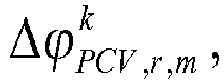


- The pseudoranges that are based on code measurements are modeled similarly as:


- The raw carrier phases are corrected for the known parameters of the receiver's position, the Earth tides, the estimated satellite position, the phase wind-up, the phase center offset and variation:

- Similarly, the pseudoranges are corrected as:

- In this section, a parameter mapping is introduced that (a) combines some of the above parameters to enable a full-rank system of observation equations and (b) combines ambiguities mainly with ambiguities to preserve the integer property of ambiguities. The mapping requires the selection of a
reference receiver 10 and reference satellite 11 being denoted by the lower/upper index ref . As thereference receiver 10 and reference satellite 11 are cluster dependent, the index c = {1,..., C} is introduced to denote all cluster dependent parameters. - The rank-defect of the absolute clock offset estimation is prevented by mapping the satellite clock offset of the reference satellite ref of cluster c to the receiver clock offset, i.e.

- The clock offsets of the other satellites are adjusted respectively:

- The code biases br,m and


- Solving for the biases of the clock offsets and ionospheric delays gives:

- The receiver clock offset is redefined and extended to:


- The slant ionospheric delay is adjusted similar as:

- The estimation of an individual receiver phase bias for each receiver, of an individual satellite phase bias for each satellite, and of an individual integer ambiguity for each link is not feasible due to a rank deficiency. The following parameter mappings is therefore performed to overcome the rank defect:
- mapping of phase bias of reference receiver to satellite phase biases
- mapping of ambiguities of reference receiver to satellite phase biases
- mapping of ambiguities of reference satellite to receiver phase biases
- Additionally, the phase biases have to be corrected for the code biases being mapped into the clock offsets and ionospheric delay. Thus, the receiver phase bias with lumped code biases and ambiguities of reference receiver and satellite is given by

- The satellite phase bias is adjusted respectively, i.e.

- The individual integer ambiguity is related to the integer ambiguity of the reference receiver and reference satellite, which results in the well-known double difference integer ambiguity:

k is the satellite index within this subset. - The undifferenced carrier phase measurements of Equation (1) can be expressed in terms of the reduced parameter set δτ̃r,c , Δδτ̃k,c , β̃r,c,m ,


- This section describes the estimation of satellite positions, clock offsets and phase biases for an individual cluster.
- The corrected carrier phase and pseudorange measurements of all receivers r ∈ {1,..., R} and frequencies m ∈ {1,..., M} in cluster c of a certain epoch are stacked in a column vector, i.e.

- Similarly, all unknowns of cluster c are stacked in the state vector x given by

- As the satellite positions and clock offsets are known from the broadcast orbits with an accuracy of 1 m and 1.5 m and as the order of magnitude of atmospheric errors and satellite phase biases is also known, we introduce some prior knowledge on these state parameters:

x . - Both measurements and prior information are linear dependent on the state vector. Thus, z and
x are combined to
x describes the error of the prior information. It is assumes that both errors can be modeled by white Gaussian noise. Colored noise is precisely modeled in BRYSON and HENRIKSON [13]. - A standard Kalman filter (see BROWN and HWANG [14]) is used to estimate x from the extended measurement vector, and denote the resulting state estimate by x̂ +. The estimated state vector also includes

- This section describes the combination of the satellite positions, clock offsets and phase bias estimates of all clusters. A multi-cluster solution is used to achieve the following benefits:
- satellites being visible from more than one cluster provide multiple correlated satellite position, clock and phase bias estimates
- a selection of a reference cluster cref enables the relation of cluster-dependent satellite phase biases to satellite phase biases of the reference cluster and to exploit integer property of double difference ambiguities related to the reference satellite of the reference cluster and any other satellite being jointly visible at reference cluster and any other cluster, and being observed by the reference stations of both clusters.
- The satellite position correction obtained from the Kalman filter of the c -th cluster can be related to the true satellite position correction:


- The estimates of the cluster-dependent satellite clock offsets of Equation (6) are related to the satellite clock offsets of the reference cluster and differential (cluster to reference cluster) satellite clock offsets, i.e.

- The estimates of the satellite phase biases


- The satellite phase bias estimates of any cluster c can be related to the satellite phase bias estimates of the reference cluster, i.e.

- The first three terms can be combined to


ref ), and map the differential ambiguity w(ref ,c,m)-w(ref ,cref,m) to v(c, m). Thus, the satellite phase bias estimate is expressed in terms of the reduced parameter set:


- The meaning, dimensions and notation of the reduced parameter set are summarized in Table 1.
- The multi-cluster solution of satellite positions, clock offsets and phase biases from the single cluster solutions is obtained by stacking the estimates of all clusters in a column vector:

- The stacked estimates of all clusters are considered as measurements that are linear related to the satellite positions, clock offsets and phase biases, i.e.


- The least-squares solution of x is given by

- The number of ambiguities in x̂ is for typical values of K, C and M much larger than the number of satellite positions, clock offsets and phase biases. Therefore, the ambiguity fixing of the multi-cluster combination is very beneficial. The method therefore uses the integer decorrelation of the LAMBDA method of [8] and bootstrapping. The real-valued states xreal are re-adjusted after ambiguity fixing as

- In this section, the performance of the proposed dual stage multi-cluster based estimation of satellite orbit, clock and phase bias corrections, tropospheric zenith and ionospheric slant delays and integer ambiguities is analyzed. Galileo measurements on the frequencies E1 and E5a of the full Galileo constellation (27 satellites) are simulated for the stations of the global IGS network. The IGS stations are grouped into 16 clusters as shown in
Figure 7 . The measurement noise was simulated as white Gaussian noise. In particular, a standard deviation of 2 mm is assumed for the phase noise and of 20 cm for the pseudorange noise. A sampling interval of 100 s was chosen. The process noise of the satellite position errors, receiver and satellite clock offsets, receiver and satellite phase biases, tropospheric zenith delays and ionospheric slant delays was modeled as Gaussian noise with a standard deviation of 1 mm/ epoch. - The convergence of the satellite position corrections of the multi-cluster combination is shown for float ambiguities in
Figure. 8 and for fixed ambiguities inFigure 9 . In both figures and also in subsequent figures, different shades of gray refer todifferent satellites 2. The float solution requires approximately 150 epochs (4 hours) to converge to a level with errors of less than 5 cm. The errors remain for almost all satellites and epochs below this threshold except for a few epochs, where some satellites show a larger error due to weak observability. However, a much faster convergence and higher stability over time can be observed after fixing of the real-valued ambiguity estimates to their integer values. In particular, it can be observed that the accuracy is better than 3 cm for almost all epochs and satellites after the initial convergence. The errors reduce to less than 5 cm within 20 epochs (33 min) and to less than 3 cm within 40 epochs (66 min). -
Figure 10 shows the accuracy of the satellite phase bias estimates referring to the reference cluster. The errors are below 0.2 cycles (4 cm) for all satellites and epochs except of a few epochs, where some satellites are only weakly observable at the reference cluster. The fixed solution is shown inFig. 11 and benefits from a lower noise level and higher stability than the float solution. One can also observe a high correlation between the errors of the satellite phase bias estimates from different satellites. -
Figure 12 shows the benefit in precision of the multi-cluster over the single-cluster solution of satellite orbit corrections, satellite clock offsets and satellite phase biases. The ambiguities were estimated as float values. The subfigures on the left side refer to the single-cluster and those on the right side refer to the multi-cluster solution. Each plotted line refers to a satellite pass. - It can be clearly seen that the single-cluster solution has a poor precision for the parameters related to satellites rising at the edge of the cluster. On the contrary, the multi-cluster solution provides orbit corrections, satellite clock offsets and phase biases with a precision varying between 8 and 50 mm for all satellites and epochs after initial convergence. In addition, a faster convergence and a lower error floor can be observed especially for the orbital and clock errors of the multi-cluster combined solution.
- The ambiguity-fixed solution is shown for the same scenario and parameters in
Figure 12 . The convergence time is significantly lower for both the single- and multi-cluster solutions. A higher precision is also achieved for the multi-cluster solution of orbit corrections, satellite clock offsets and phase biases with a standard deviation between 5 and 20 mm for all satellites. - For validating the proposed estimation of satellite position, clock and phase bias corrections, tropospheric zenith and ionospheric slant delays and integer ambiguities with real GPS measurements, the Multi-GNSS Experiment (MGEX) stations described in MONTENBRUCK [15] were used and 11 clusters were defined as shown in
Figure 12 . The reference cluster and the reference receiver of each cluster are highlighted. The number of receivers per cluster is additionally provided in the upper left corner of each cluster. - A pre-processing was performed to eliminate outliers, to correct for cycle slips and to estimate the measurement noise statistics. The process noise statistics were modeled according to Table 2.
-
Figure. 15 shows the estimates of the L1 satellite phase biases of the single-cluster solution of the Western European cluster for float ambiguities. A stable behaviour is observed for the phase bias estimates of almost all satellites. The convergence time ranges from a few to several hours. Therefore, the phase bias estimates referring to satellites being observed only for a short amount of time do not converge sufficiently. -
Figure 16 illustrates the achieved precision of the L1 satellite phase bias estimates. The convergence time for satellite phase bias estimates of newly tracked satellites is in the order of three hours. A precision of 0.05 and 0.20 cycles, or 1 and 4 cm respectively, is achieved after initial convergence. -
Figure 17 shows the fixed phase measurement residuals forDOY 150/2017, derived again from the Western European single cluster solution. The residuals are an indicator for the quality of the measurement model and the used observations, since the former include the measurement noise, multipath and other unmodelled effects. The phase residuals do not exceed the level of 3 cm, and remain even below 1 cm for 99.7% of the time, which confirms the high quality of the selected data. -
Figure 18 presents a more precise picture of the satellite phase bias estimates by depicting the L1 satellite phase biases of four representative GPS satellites, plus their formal standard deviations. It can be clearly seen that the satellite phase biases show a high stability with variations between 2 and 5 cm per hour during a satellite's pass. An hour or even less is sufficient for the bias estimates to converge to an almost constant value. It has to be noted that the value of the satellite phase biases is irrelevant, as the phase bias and ambiguity of the reference receiver are mapped to the absolute satellite phase biases. Moreover, the formal precision of the satellite phase biases on L1 reaches the 0.10 cycles ( : 2 cm) level after 2 hours, while the stable level of 0.05 cycles (: 1 cm) is achieved after about 5 hours. -
Figure 19 shows the widelane (L1-L2) satellite phase bias estimates obtained by differencing the satellite phase bias estimates on frequencies L1 and L2. The errors of the satellite phase bias estimates on frequencies L1 and L2 are highly correlated and mostly drop by differencing. Therefore, the widelane phase bias estimates show an even higher stability over time than the uncombined satellite phase bias estimates on L1 and L2. - The method described herein can be used for the estimation of satellite position, clock and phase bias corrections, tropospheric zenith and ionospheric slant delays, and integer ambiguities with a global network of reference stations. Undifferenced and uncombined measurements of an arbitrary number of frequencies were processed such that the method can be applied to any type of differenced or combined measurements. The method uses a parameter mapping, that enables a full rank system and maintains the integer property of ambiguities for a maximum number of ambiguities. This mapping was derived from a global perspective.
- The method splits the global network into multiple clusters and selects a reference receiver and reference satellite within each cluster as well as one reference cluster among all clusters. The clustering enables a common satellite visibility within each cluster and, thus, the exploitation of the integer property of double difference ambiguities. A Kalman filter was set up for each cluster to estimate satellite position, clock and phase bias corrections, atmospheric delays and ambiguities. An integer decorrelation and sequential adjustment was used to fix the double difference ambiguities within each cluster, and to adjust all other state parameters respectively. Subsequently, the satellite position, clock and phase bias corrections of each cluster were combined into a global multi-cluster solution by a least-squares estimation. Finally, an integer decorrelation and sequential adjustment was used again to fix the double difference ambiguities related to reference stations of different clusters, and to re-adjust the other state parameters.
- The proposed method was validated with both simulated Galileo measurements and real GPS measurements of the global IGS network. It was possible to obtain satellite position, clock and phase bias corrections with an accuracy of better than 2 cm.
- It should be noted that the method described here in detail, includes the determination of particular parameters. This is based on a typical scenario in which the parameters cannot be deriverd otherwise. If the parameters, however, can be determined by other means, it might be possible to reduce the set of parameters to be determined.
- It should also be noted that the method can be implemented by a computer program product, that contains code for implementing the method described herein, if the code is executed by a processor either in one of the
base station 8 or theprocessing unit 14 connected to the network 12 including thebase stations 8. In some embodiments, the computer program product may be code stored on a computer readable data carrier such as a disc, a compact disc or a digital versatile disc or the like. In other embodiments, the computer program product may also be code stored on a data storage unit on a server or an array of servers. Such a data storage unit may be a hard disc or an array of hard disc or the like. In further embodiments, the data carrier may also be an electrical carrier signal that can be used for transferring the code from a server, which can be used for downloading the program code to a client. - It should further be noted that throughout the description and claims of this specification, the singular encompasses the plural unless the context otherwise requires. In particular, where the indefinite article is used, the specification is to be understood as contemplating plurality as well as singularity, unless the context requires otherwise.
- Features, integers, characteristics, compounds or groups described in conjunction with a particular aspect, embodiment or example of the invention are to be understood to be applicable to any other aspect, embodiment or example described herein unless incompatible therewith.
Table 1: Main characteristics of the reduced parameter set for the combined solution of multiple cluster-wise solutions (C, K and M denote the number of clusters, satellites and frequencies.) Notation Dimensions Lumped parameters satellite phase biases ũ(k,m) KM - satellite code biases - receiver phase and code biases of ref. receiver at ref. cluster - integer ambiguity of ref. receiver at ref. cluster receiver phase biases ũ(k,m) (C-1)M - receiver phase bias of ref. receiver at ref. cluster - integer ambiguities of ref. receiver at cluster and ref. cluster double difference integer ambiguities between ref. receivers at ref. cluster and any other cluster w̃(k,c,m) (C-1)M(K-1) Table 2: Process noise statistics and accuracy of prior information State parameters σ x σ X Satellite position corrections 0.02 m 1.0 m Receiver clock offsets 1 m - Satellite clock offset corrections 1 m 1.5 m Tropospheric zenith delays 0.002 m - Ionospheric slant delays 0.02 m - Receiver phase biases 0.001 m - Satellite phase biases 0.001 m - Integer ambiguities 0 - -
- [1] Zumberge JF, Heflin MB, Jefferson DC, Watkins MM, Webb FH (1997) Precise Point Positioning for the efficient and robust analysis of GPS data from large networks. J of Geophysical Research 102:5005-5017
- [2] Kouba J, Héroux P (2000) GPS Precise Point Positioning using IGS orbit products. GPS Solutions 5:12-28
- [3] Dach R, Hugentobler U, Fridez P, Meindl M (2007) Bernese GPS Software Version 5.0, User manual. Astronomical Institute, University of Bern, Switzerland
- [4] Ge M, Gendt G, Rothacher M, Shi C, Liu J (2008) Resolution of GPS carrier-phase ambiguities in Precise Point Positioning (PPP) with daily observations. Journal of Geodesy 82:389-399
- [5] Laurichesse D, Mercier F, Berthias JP (2010) Real-time PPP with undifferenced integer ambiguity resolution, experimental results. In: Proc. of 23rd ION GNSS, ION, Portland, Oregon, USA, pp 2534-2544
- [6] Wen Z, Henkel P, Günther C (2011) Reliable Estimation of Phase Biases of GPS Satellites with a Local Reference Network. In: Proc. of 53rd Int. IEEE Symp. ELMAR, IEEE, Zadar, Croatia, pp 321-324
- [7] Blewitt G (1989) Carrier Phase Ambiguity Resolution for the Global Positioning System Applied to Geodetic Baselines up to 2000 km. J of Geophysical Research 94(B8):10,187-10,203
- [8] Teunissen PJG (1995) The least-squares ambiguity decorrelation adjustment: a method for fast GPS ambiguity estimation. Journal of Geodesy 70:65-82
- [9] Teunissen PJG (1998) Success probability of integer GPS ambiguity rounding and bootstrapping. Journal of Geodesy 72:606-612
- [10] Brack A, Henkel P, Günther C (2013) Sequential Best Integer-Equivariant Estimation for Geodetic Network Solutions. In: Proc. of ION ITM, ION, San Diego, CA, USA, pp 310-317
- [11] Henkel P, Mittmann U, Iafrancesco M (2016) Real-time Kinematic Positioning with GPS and GLONASS. In: Proc. of 24th European Signal Processing Conference (EUSIPCO), IEEE, Budapest, Hungary, pp 1-5
- [12] Li X, Ge M, Dousa J Wickert J (2014) Real time precise point positioning regional augmentation for large GPS reference networks.
- [13] Bryson AE, Henrikson LJ (1968) Estimation using sampled data containing sequentially correlated noise. Journal of Spacecraft and Rockets 5(6):662-665
- [14] Brown RG, Hwang PYC (2012) Introduction to Random Signals and Applied Kalman Filtering
- [15] Montenbruck O, Steigenberger P, Prange L, Deng Z, Zhao Q, Perosanz F, Romero I, Noll C, St¨urze A, Weber G, Schmid R, MacLeod K, Schaer S (2016) The Multi-GNSS Experiment (MGEX) of the International GNSS Service (IGS) - Achievements, Prospects and Challenges. Advances in Space Research 59(7):1671-1697
Claims (15)
- A method for Precise Point Positioning in a satellite navigation system (1) comprising a plurality of navigations satellites (2) and a plurality of base stations (8) each provided with a receiver (7) that receives satellite signals (4) and is used for determining ambiguity-free phase biases and further instrumental and atmospheric errors wherein the errors are arranged for being transmitted to navigation devices (6) and arranged for being used by the navigation devices (6) for performing Precise Point Positioning including ambiguity fixing, the method comprising the steps:- obtaining code and phase measurements which were performed on the satellite signals (4) by the plurality of receivers (7) at two or more frequencies,- determining separate individual values for a plurality of phase ambiguities and a plurality of the errors based on the code and phase measurements,
characterized in that- the receivers (7) are grouped into clusters (9),- in each cluster (9) a determination (16) of a single cluster solution is performed, in which satellite errors selected from the group of satellite position errors, satellite clock errors and satellite phase biases are determined based on the phase and code measurements performed by the receivers (7) of the respective cluster (9);- a determination (17) of a multi-cluster solution is performed, in which values of the selected satellite errors, which were determined in different clusters (9) are adjusted by an estimation process (33) applied to the values of the selected errors determined in different clusters. - The method according to claim 1,
wherein the vector elements of the measurement vector formed for the determination of the single cluster solution are undifferenced and uncombined code and phase measurements. - The method according to claim 1 or 2,
wherein the determination of the single cluster solution comprises the following method steps:- the code and phase measurements are used to form (21) a measurement vector,- variables for unknown phase ambiguities and unknown errors are mapped into other variables in order to establish (23) a state vector and a full-rank observation matrix between the measurement vector and the state vector, and- a recursive state estimator (26) is performed using the observation matrix for estimating values for the variables in each cluster (9). - The method according to claim 3,
wherein, in each cluster (9), phase ambiguities are determined together with the selected satellite error and an intermediate phase ambiguity fixing is performed while performing the recursive state estimator. - The method according to any one of claims 1 to 4,
wherein, in each cluster (9), a temporal reference satellite (11) is selected among the satellites (2) associated with the cluster (9), wherein instrumental errors of the satellites (2) associated with the respective cluster (9) are determined as differential errors with respect to the errors of the respective reference satellite (11). - The method according to any one of claims 1 to 5,
wherein, in each cluster (9), a permanent reference receiver (10) is selected. - The method according to any one of claims 1 to 6,
wherein, in each cluster (9), the state vector comprises a selection of parameters selected from the group including satellite position corrections, receiver and satellite clock errors, tropospheric zenith delays, slant ionospheric delays, receiver and satellite phase biases, and double difference integer ambiguities. - The method according to claim 7,
wherein, in each cluster (9):- the satellite clock error and satellite code biases are mapped into the receiver clock errors,- the phase bias and the phase ambiguities of the reference receiver are mapped to satellite phase biases, and- the ambiguities of the reference satellite are mapped to receiver biases. - The method according to any one of claims 1 to 8,
wherein the determination (17) of the multi-cluster solution comprises the following method steps:- the results obtained for the state vector by performing the determination of a single cluster solution are used to form a composed further measurement vector,- variables for phase biases and phase ambiguities to be determined are mapped into other phase biases and phase ambiguities and composed with variables for the selected satellite errors to establish a further state vector and a full-rank observation matrix between the further measurement vector and the further state vector, and- values for the variables of the state vector are estimated by a least-square-estimation. - The method according to claim 9,
wherein the least-square-estimation is followed by a method step (34) in which the phase ambiguities are fixed, and a further method step (35), in which the selected satellite error are adjusted. - The method according to claims 9 or 10 in combination with claim 7,
wherein one of the clusters (9) is selected as a reference cluster (12) and wherein the further state vector comprises:- the satellite position errors,- satellite clock offsets, which relate to the reference satellite clock errors of the reference cluster (12) and include a differential satellite clock error, that is defined as the difference between the reference satellite clock error of the respective cluster and the satellite clock errors at the reference cluster (12),- satellite phase biases, in which the satellite code biases, the receiver phase and code biases and phase ambiguities of the reference receiver (10) at the reference cluster (12) are mapped,- receiver phase biases, in which the receiver phase bias of the reference receiver (10) at the reference cluster (12) and integer ambiguities of the reference receiver (10) at the reference cluster (12) and at any other cluster (9) are mapped.- double difference integer ambiguities between the reference receivers (10) at the reference cluster (12) and any other cluster (9). - The method according to any one of claims 1 to 11,
wherein the cluster are non-overlapping clusters (9). - A network of base stations (8) for a satellite navigation system, the network comprising a plurality of base stations (8) arranged for receiving satellite signals (4) from a plurality of navigation satellites (2) and wherein the network is arranged for determining ambiguity-free phase biases and further instrumental and atmospheric errors wherein the errors are provided for being transmitted to navigation devices (6) and provided for being used by the navigation devices (6) for performing Precise Point Positioning including ambiguity fixing
characterized in that
the network of base stations is arranged for performing a method according to any one of claims 1 to 12. - A software product,
characterized in that
the software product contains program code for implementing any one of the methods according to any one of claims 1 to 12. - A mobile navigation device for Precise Point Positioning comprising a receiver for receiving satellite navigation signals (4) and a processing unit for processing the satellite navigation signal (4) for obtaining a position of the mobile navigation device,
characterized in that
the processing unit is arranged for receiving the errors obtained by the method according to any of claims 1 to 12 and for processing the errors for navigation purposes.
Priority Applications (4)
| Application Number | Priority Date | Filing Date | Title |
|---|---|---|---|
| EP17193912.7A EP3462213B1 (en) | 2017-09-28 | 2017-09-28 | Method for precise point positioning in a satellite navigation system |
| CA3113865A CA3113865A1 (en) | 2017-09-28 | 2018-09-26 | Method for precise point positioning in a satellite navigation system |
| US16/651,864 US11573328B2 (en) | 2017-09-28 | 2018-09-26 | Method for precise point positioning in a satellite navigation system |
| PCT/EP2018/076182 WO2019063645A1 (en) | 2017-09-28 | 2018-09-26 | Method for precise point positioning in a satellite navigation system |
Applications Claiming Priority (1)
| Application Number | Priority Date | Filing Date | Title |
|---|---|---|---|
| EP17193912.7A EP3462213B1 (en) | 2017-09-28 | 2017-09-28 | Method for precise point positioning in a satellite navigation system |
Publications (2)
| Publication Number | Publication Date |
|---|---|
| EP3462213A1 true EP3462213A1 (en) | 2019-04-03 |
| EP3462213B1 EP3462213B1 (en) | 2026-04-29 |
Family
ID=59997201
Family Applications (1)
| Application Number | Title | Priority Date | Filing Date |
|---|---|---|---|
| EP17193912.7A Active EP3462213B1 (en) | 2017-09-28 | 2017-09-28 | Method for precise point positioning in a satellite navigation system |
Country Status (4)
| Country | Link |
|---|---|
| US (1) | US11573328B2 (en) |
| EP (1) | EP3462213B1 (en) |
| CA (1) | CA3113865A1 (en) |
| WO (1) | WO2019063645A1 (en) |
Cited By (5)
| Publication number | Priority date | Publication date | Assignee | Title |
|---|---|---|---|---|
| CN110045634A (en) * | 2019-05-09 | 2019-07-23 | 自然资源部第二大地测量队(黑龙江第一测绘工程院) | A kind of non-mistake difference modeling method of GNSS base station |
| CN114895327A (en) * | 2022-05-10 | 2022-08-12 | 国汽大有时空科技(安庆)有限公司 | Multi-system UPD product estimation and checking method |
| CN116449400A (en) * | 2023-06-19 | 2023-07-18 | 武汉大学 | A Beidou-3 PPP service real-time satellite clock error evaluation method and system |
| CN119030654A (en) * | 2024-10-28 | 2024-11-26 | 中国人民解放军国防科技大学 | Satellite network distributed time synchronization control method and system |
| CN120011469A (en) * | 2025-02-12 | 2025-05-16 | 武汉大学 | A method and system for determining earth rotation parameters based on GNSS data stream |
Families Citing this family (30)
| Publication number | Priority date | Publication date | Assignee | Title |
|---|---|---|---|---|
| US9933528B2 (en) | 2014-10-27 | 2018-04-03 | Swift Navigation, Inc. | Systems and methods for real time kinematic satellite positioning |
| US10274606B1 (en) | 2016-03-09 | 2019-04-30 | Rockwell Collins, Inc. | High integrity partial almost fix solution |
| US10473790B2 (en) | 2017-11-17 | 2019-11-12 | Swift Navigation, Inc. | Systems and methods for distributed dense network processing of satellite positioning data |
| US10578747B2 (en) | 2017-12-14 | 2020-03-03 | Swift Navigation, Inc. | Systems and methods for reduced-outlier satellite positioning |
| US11363643B2 (en) | 2018-08-10 | 2022-06-14 | Telefonaktiebolaget Lm Ericsson (Publ) | Random access procedures for satellite communications |
| US11079496B2 (en) * | 2018-08-27 | 2021-08-03 | Industrial Technology Research Institute | Precise point positioning method and positioning apparatus and recording medium thereof |
| EP3857734B1 (en) * | 2018-09-27 | 2024-04-17 | Telefonaktiebolaget LM Ericsson (publ) | Device and method for timing adaptation for satellite communications |
| EP3963352A4 (en) | 2019-05-01 | 2023-09-20 | Swift Navigation, Inc. | Systems and methods for high-integrity satellite positioning |
| WO2021119493A1 (en) | 2019-12-11 | 2021-06-17 | Swift Navigation, Inc. | System and method for validating gnss ambiguities |
| EP4103973A4 (en) | 2020-02-14 | 2024-06-05 | Swift Navigation, Inc. | System and method for reconverging gnss position estimates |
| CN116075747A (en) | 2020-06-09 | 2023-05-05 | 斯威夫特导航股份有限公司 | Systems and methods for satellite positioning |
| WO2022015744A1 (en) | 2020-07-13 | 2022-01-20 | Swift Navigation, Inc. | System and method for determining gnss positioning corrections |
| CN111982128B (en) * | 2020-08-21 | 2022-03-18 | 上海航天控制技术研究所 | On-orbit calibration method of gyro installation matrix and satellite-borne software |
| US11550067B2 (en) | 2020-12-17 | 2023-01-10 | Swift Navigation, Inc. | System and method for fusing dead reckoning and GNSS data streams |
| CN112924999B (en) * | 2021-01-14 | 2023-08-22 | 华南理工大学 | A positioning method, system, device and medium for an unmanned aerial vehicle |
| CN113050135B (en) * | 2021-03-26 | 2022-09-13 | 同济大学 | Low-cost GNSS terminal data exception handling method |
| US11606756B2 (en) | 2021-03-29 | 2023-03-14 | Snap Inc. | Scheduling requests for location data |
| CN113156369B (en) * | 2021-04-26 | 2021-10-29 | 哈尔滨工程大学 | A marine acoustic phase center calibration method |
| US11733397B2 (en) | 2021-07-24 | 2023-08-22 | Swift Navigation, Inc. | System and method for computing positioning protection levels |
| US11693120B2 (en) | 2021-08-09 | 2023-07-04 | Swift Navigation, Inc. | System and method for providing GNSS corrections |
| US20230184956A1 (en) | 2021-12-10 | 2023-06-15 | Swift Navigation, Inc. | System and method for correcting satellite observations |
| US11860287B2 (en) | 2022-03-01 | 2024-01-02 | Swift Navigation, Inc. | System and method for detecting outliers in GNSS observations |
| WO2023167899A1 (en) | 2022-03-01 | 2023-09-07 | Swift Navigation, Inc. | System and method for fusing sensor and satellite measurements for positioning determination |
| EP4273584A1 (en) * | 2022-05-04 | 2023-11-08 | u-blox AG | Precise point positioning methods, devices and systems |
| US12013468B2 (en) | 2022-09-01 | 2024-06-18 | Swift Navigation, Inc. | System and method for determining GNSS corrections |
| WO2024058999A1 (en) * | 2022-09-12 | 2024-03-21 | Swift Navigation, Inc. | System and method for gnss correction transmission |
| US12498493B2 (en) | 2022-10-21 | 2025-12-16 | Swift Navigation, Inc. | System and method for distributed integrity monitoring |
| CN116299618B (en) * | 2023-03-24 | 2024-03-19 | 中国科学院精密测量科学与技术创新研究院 | Carrier phase satellite common view time transfer method based on PPP (point-to-point protocol) calculation parameters |
| CN116879927B (en) * | 2023-09-06 | 2023-11-21 | 智慧司南(天津)科技发展有限公司 | Ship satellite compass heading determination method based on three-antenna collinear common clock architecture |
| CN121541232B (en) * | 2026-01-21 | 2026-04-03 | 武汉大学 | A method and apparatus for detecting anomaly observations in precise single-point positioning using a multi-satellite system |
Family Cites Families (4)
| Publication number | Priority date | Publication date | Assignee | Title |
|---|---|---|---|---|
| NL2009695C2 (en) * | 2012-10-25 | 2014-05-06 | Fugro N V | Ppp-rtk method and system for gnss signal based position determination. |
| NL2013472B1 (en) * | 2014-09-15 | 2016-09-28 | Fugro N V | Integer Ambiguity-Fixed Precise Point Positioning method and system. |
| US10422884B2 (en) * | 2015-02-26 | 2019-09-24 | Profound Positioning Inc. | Method and system for performing precise point positioning (PPP) ambiguity resolution using GNSS triple frequency signals |
| US10222483B2 (en) * | 2016-03-18 | 2019-03-05 | Deere & Company | Satellite navigation receiver with improved ambiguity resolution |
-
2017
- 2017-09-28 EP EP17193912.7A patent/EP3462213B1/en active Active
-
2018
- 2018-09-26 US US16/651,864 patent/US11573328B2/en active Active
- 2018-09-26 CA CA3113865A patent/CA3113865A1/en active Pending
- 2018-09-26 WO PCT/EP2018/076182 patent/WO2019063645A1/en not_active Ceased
Non-Patent Citations (19)
| Title |
|---|
| BLEWITT G: "Carrier Phase Ambiguity Resolution for the Global Positioning System Applied to Geodetic Baselines up to 2000 km", J OF GEOPHYSICAL RESEARCH, vol. 94, no. B8, 1989, pages 10,187 - 10,203 |
| BRACK A ET AL: "Sequential Best Integer-Equivariant Estimation for Geodetic Network Solutions", ITM 2013 - PROCEEDINGS OF THE 2013 INTERNATIONAL TECHNICAL MEETING OF THE INSTITUTE OF NAVIGATION, THE INSTITUTE OF NAVIGATION, 8551 RIXLEW LANE SUITE 360 MANASSAS, VA 20109, USA, 27 January 2013 (2013-01-27), pages 310 - 317, XP056007972 * |
| BRACK A; HENKEL P; GUNTHER C: "Sequential Best Integer-Equivariant Estimation for Geodetic Network Solutions", PROC. OF ION ITM, ION, 2013, pages 310 - 317, XP056007972 |
| BROWN RG; HWANG PYC, INTRODUCTION TO RANDOM SIGNALS AND APPLIED KALMAN FILTERING, 2012 |
| BRYSON AE; HENRIKSON LJ: "Estimation using sampled data containing sequentially correlated noise", JOURNAL OF SPACECRAFT AND ROCKETS, vol. 5, no. 6, 1968, pages 662 - 665 |
| DACH R; HUGENTOBLER U; FRIDEZ P; MEINDL M: "User manual", 2007, ASTRONOMICAL INSTITUTE, UNIVERSITY OF BERN, article "Bernese GPS Software Version 5.0" |
| GE M; GENDT G; ROTHACHER M; SHI C; LIU J: "Resolution of GPS carrier-phase ambiguities in Precise Point Positioning (PPP) with daily observations", JOURNAL OF GEODESY, vol. 82, 2008, pages 389 - 399, XP019620115 |
| HENKEL P; MITTMANN U; IAFRANCESCO M: "Proc. of 24th European Signal Processing Conference (EUSIPCO", 2016, IEEE, article "Real-time Kinematic Positioning with GPS and GLONASS", pages: 1 - 5 |
| KOUBA J; HEROUX P: "GPS Precise Point Positioning using IGS orbit products", GPS SOLUTIONS, vol. 5, 2000, pages 12 - 28 |
| LAURICHESSE D; MERCIER F; BERTHIAS JP: "Real-time PPP with undifferenced integer ambiguity resolution, experimental results", PROC. OF 23RD ION GNSS, ION, 2010, pages 2534 - 2544, XP056000358 |
| LI X; GE M; DOUSA J; WICKERT J: "Real time precise point positioning regional augmentation for large GPS reference networks", GPS SOLUSTIONS, vol. 19, 2014, pages 61 - 71 |
| MONTENBRUCK O; STEIGENBERGER P; PRANGE L; DENG Z; ZHAO Q; PEROSANZ F; ROMERO I; NOLL C; SF'URZE A; WEBER G: "The Multi-GNSS Experiment (MGEX) of the International GNSS Service (IGS) - Achievements, Prospects and Challenges", ADVANCES IN SPACE RESEARCH, vol. 59, no. 7, 2016, pages 1671 - 1697 |
| RADEMAKERS ERWIN ET AL: "Obtaining real-time sub-meter accuracy using a low cost GNSS device", 2016 EUROPEAN NAVIGATION CONFERENCE (ENC), IEEE, 30 May 2016 (2016-05-30), pages 1 - 8, XP032935312, [retrieved on 20160802], DOI: 10.1109/EURONAV.2016.7530555 * |
| SEEPERSAD G ET AL: "Examining the Interoperability of PPP-AR Products", GNSS 2015 - PROCEEDINGS OF THE 28TH INTERNATIONAL TECHNICAL MEETING OF THE SATELLITE DIVISION OF THE INSTITUTE OF NAVIGATION (ION GNSS+ 2015), THE INSTITUTE OF NAVIGATION, 8551 RIXLEW LANESUITE 360MANASSAS, VA 20109, USA, 18 September 2015 (2015-09-18), pages 2845 - 2857, XP056011055 * |
| TEUNISSEN PJG: "Success probability of integer GPS ambiguity rounding and bootstrapping", JOURNAL OF GEODESY, vol. 72, 1998, pages 606 - 612 |
| TEUNISSEN PJG: "The least-squares ambiguity decorrelation adjustment: a method for fast GPS ambiguity estimation", JOURNAL OF GEODESY, vol. 70, 1995, pages 65 - 82 |
| WEN Z ET AL: "Satellite Bias Determination with Global Station Network and Best-Integer Equivariant Estimation", GNSS 2012 - PROCEEDINGS OF THE 25TH INTERNATIONAL TECHNICAL MEETING OF THE SATELLITE DIVISION OF THE INSTITUTE OF NAVIGATION (ION GNSS 2012), THE INSTITUTE OF NAVIGATION, 8551 RIXLEW LANE SUITE 360 MANASSAS, VA 20109, USA, 21 September 2012 (2012-09-21), pages 3675 - 3682, XP056008647 * |
| WEN Z; HENKEL P; GUNTHER C: "Proc. of 53rd Int. IEEE Symp. ELMAR", 2011, IEEE, article "Reliable Estimation of Phase Biases of GPS Satellites with a Local Reference Network", pages: 321 - 324 |
| ZUMBERGE JF; HEFLIN MB; JEFFERSON DC; WATKINS MM; WEBB FH: "Precise Point Positioning for the efficient and robust analysis of GPS data from large networks", J OF GEOPHYSICAL RESEARCH, vol. 102, 1997, pages 5005 - 5017 |
Cited By (7)
| Publication number | Priority date | Publication date | Assignee | Title |
|---|---|---|---|---|
| CN110045634A (en) * | 2019-05-09 | 2019-07-23 | 自然资源部第二大地测量队(黑龙江第一测绘工程院) | A kind of non-mistake difference modeling method of GNSS base station |
| CN114895327A (en) * | 2022-05-10 | 2022-08-12 | 国汽大有时空科技(安庆)有限公司 | Multi-system UPD product estimation and checking method |
| CN116449400A (en) * | 2023-06-19 | 2023-07-18 | 武汉大学 | A Beidou-3 PPP service real-time satellite clock error evaluation method and system |
| CN116449400B (en) * | 2023-06-19 | 2023-08-29 | 武汉大学 | Real-time satellite clock error evaluation method and system for Beidou No. three PPP service |
| CN119030654A (en) * | 2024-10-28 | 2024-11-26 | 中国人民解放军国防科技大学 | Satellite network distributed time synchronization control method and system |
| CN119030654B (en) * | 2024-10-28 | 2025-02-07 | 中国人民解放军国防科技大学 | Satellite network distributed time synchronization control method and system |
| CN120011469A (en) * | 2025-02-12 | 2025-05-16 | 武汉大学 | A method and system for determining earth rotation parameters based on GNSS data stream |
Also Published As
| Publication number | Publication date |
|---|---|
| EP3462213B1 (en) | 2026-04-29 |
| CA3113865A1 (en) | 2019-04-04 |
| US20200257002A1 (en) | 2020-08-13 |
| WO2019063645A1 (en) | 2019-04-04 |
| US11573328B2 (en) | 2023-02-07 |
Similar Documents
| Publication | Publication Date | Title |
|---|---|---|
| EP3462213B1 (en) | Method for precise point positioning in a satellite navigation system | |
| CN108415049B (en) | Method for improving network RTK double-difference wide lane ambiguity fixing accuracy | |
| EP2336807B1 (en) | Method and software product for determining code and phase biases of satellite signals | |
| EP1704421B1 (en) | A method for combined use of a local rtk system and a regional, wide-area, or global carrier-phase positioning system | |
| Teunissen et al. | PPP-RTK: results of CORS network-based PPP with integer ambiguity resolution | |
| US8094065B2 (en) | Method for processing a set of signals of a global navigation satellite system with at least three carriers | |
| CN111751853A (en) | GNSS double-frequency carrier phase integer ambiguity resolution method | |
| EP3430433A1 (en) | Navigation satellite orbit and clock determination with low latency clock corrections | |
| CN106338738A (en) | Pierce point-based regional augmentation system real-time ionosphere modeling method | |
| CN109212562A (en) | A method of generating carrier wave pseudo range observed quantity | |
| CN108508470A (en) | Towards the instantaneous decimeter grade navigation locating method that the whole world is seamless | |
| Kabir et al. | Performance evaluation of GNSS positioning with geometric dilution of precision | |
| Bisnath | Relative Positioning and Real‐Time Kinematic (RTK) | |
| Amami | Investigations into the quality of final-product dual-frequency static PPP over fixing time using CSRS-PPP free online service: GPS Vs. GPS+ GLONASS | |
| Amami | Investigations into the quality of final-product dual frequency kinematic PPP in open sky using CSRSPPP free online service: GPS Vs. GPS+ GLONASS | |
| Amami | Kinematic PPP Using PPP-WIZARD Free Online Service: GPS Vs. GPS+ GLONASS | |
| Amami | Dual-Frequency Static PPP Over Fixing Time Using Final-Product Free Online Services: CSRS-PPP Vs. PPP-WIZARD Vs. APPS | |
| Ogutcu | Performance analysis of ambiguity resolution on PPP and relative positioning techniques: consideration of satellite geometry | |
| Li et al. | Assessment and analysis of the four-satellite QZSS precise point positioning and the integrated data processing with GPS | |
| Henkel et al. | Estimation of satellite position, clock and phase bias corrections | |
| Wang et al. | GPS un-differenced ambiguity resolution and validation | |
| Feng et al. | Multiple carrier ambiguity resolution and performance benefits for RTK and PPP positioning services in regional areas | |
| Vaclavovic et al. | COMPARISON AND ASSESSMENT OF FLOAT, FIXED, AND SMOOTHED PRECISE POINT POSITIONING. | |
| Deo et al. | Precise point positioning with decimetre accuracy using wide-lane ambiguities and triple-frequency GNSS data | |
| Amami | Dual-frequency static GNSS solution over fixing time using Trimble RTX-PP free online service: GPS Vs. GPS+ GLONASS |
Legal Events
| Date | Code | Title | Description |
|---|---|---|---|
| PUAI | Public reference made under article 153(3) epc to a published international application that has entered the european phase |
Free format text: ORIGINAL CODE: 0009012 |
|
| STAA | Information on the status of an ep patent application or granted ep patent |
Free format text: STATUS: THE APPLICATION HAS BEEN PUBLISHED |
|
| AK | Designated contracting states |
Kind code of ref document: A1 Designated state(s): AL AT BE BG CH CY CZ DE DK EE ES FI FR GB GR HR HU IE IS IT LI LT LU LV MC MK MT NL NO PL PT RO RS SE SI SK SM TR |
|
| AX | Request for extension of the european patent |
Extension state: BA ME |
|
| STAA | Information on the status of an ep patent application or granted ep patent |
Free format text: STATUS: REQUEST FOR EXAMINATION WAS MADE |
|
| 17P | Request for examination filed |
Effective date: 20191002 |
|
| RBV | Designated contracting states (corrected) |
Designated state(s): AL AT BE BG CH CY CZ DE DK EE ES FI FR GB GR HR HU IE IS IT LI LT LU LV MC MK MT NL NO PL PT RO RS SE SI SK SM TR |
|
| STAA | Information on the status of an ep patent application or granted ep patent |
Free format text: STATUS: EXAMINATION IS IN PROGRESS |
|
| 17Q | First examination report despatched |
Effective date: 20230719 |
|
| RAP1 | Party data changed (applicant data changed or rights of an application transferred) |
Owner name: ANAVS GMBH |
|
| GRAP | Despatch of communication of intention to grant a patent |
Free format text: ORIGINAL CODE: EPIDOSNIGR1 |
|
| STAA | Information on the status of an ep patent application or granted ep patent |
Free format text: STATUS: GRANT OF PATENT IS INTENDED |
|
| INTG | Intention to grant announced |
Effective date: 20251121 |
|
| GRAS | Grant fee paid |
Free format text: ORIGINAL CODE: EPIDOSNIGR3 |
|
| GRAA | (expected) grant |
Free format text: ORIGINAL CODE: 0009210 |
|
| STAA | Information on the status of an ep patent application or granted ep patent |
Free format text: STATUS: THE PATENT HAS BEEN GRANTED |
|
| AK | Designated contracting states |
Kind code of ref document: B1 Designated state(s): AL AT BE BG CH CY CZ DE DK EE ES FI FR GB GR HR HU IE IS IT LI LT LU LV MC MK MT NL NO PL PT RO RS SE SI SK SM TR |
|
| REG | Reference to a national code |
Ref country code: CH Ref legal event code: F10 Free format text: ST27 STATUS EVENT CODE: U-0-0-F10-F00 (AS PROVIDED BY THE NATIONAL OFFICE) Effective date: 20260429 Ref country code: GB Ref legal event code: FG4D |