EP3462029A1 - Gas leak determining method, and multi-stage compressor - Google Patents
Gas leak determining method, and multi-stage compressor Download PDFInfo
- Publication number
- EP3462029A1 EP3462029A1 EP17833934.7A EP17833934A EP3462029A1 EP 3462029 A1 EP3462029 A1 EP 3462029A1 EP 17833934 A EP17833934 A EP 17833934A EP 3462029 A1 EP3462029 A1 EP 3462029A1
- Authority
- EP
- European Patent Office
- Prior art keywords
- compressing unit
- compressing
- gas
- unit
- proportion
- Prior art date
- Legal status (The legal status is an assumption and is not a legal conclusion. Google has not performed a legal analysis and makes no representation as to the accuracy of the status listed.)
- Granted
Links
Images

Classifications
-
- F—MECHANICAL ENGINEERING; LIGHTING; HEATING; WEAPONS; BLASTING
- F04—POSITIVE - DISPLACEMENT MACHINES FOR LIQUIDS; PUMPS FOR LIQUIDS OR ELASTIC FLUIDS
- F04B—POSITIVE-DISPLACEMENT MACHINES FOR LIQUIDS; PUMPS
- F04B25/00—Multi-stage pumps
- F04B25/02—Multi-stage pumps of stepped piston type
-
- F—MECHANICAL ENGINEERING; LIGHTING; HEATING; WEAPONS; BLASTING
- F04—POSITIVE - DISPLACEMENT MACHINES FOR LIQUIDS; PUMPS FOR LIQUIDS OR ELASTIC FLUIDS
- F04B—POSITIVE-DISPLACEMENT MACHINES FOR LIQUIDS; PUMPS
- F04B25/00—Multi-stage pumps
-
- F—MECHANICAL ENGINEERING; LIGHTING; HEATING; WEAPONS; BLASTING
- F04—POSITIVE - DISPLACEMENT MACHINES FOR LIQUIDS; PUMPS FOR LIQUIDS OR ELASTIC FLUIDS
- F04B—POSITIVE-DISPLACEMENT MACHINES FOR LIQUIDS; PUMPS
- F04B25/00—Multi-stage pumps
- F04B25/005—Multi-stage pumps with two cylinders
-
- F—MECHANICAL ENGINEERING; LIGHTING; HEATING; WEAPONS; BLASTING
- F04—POSITIVE - DISPLACEMENT MACHINES FOR LIQUIDS; PUMPS FOR LIQUIDS OR ELASTIC FLUIDS
- F04B—POSITIVE-DISPLACEMENT MACHINES FOR LIQUIDS; PUMPS
- F04B41/00—Pumping installations or systems specially adapted for elastic fluids
- F04B41/06—Combinations of two or more pumps
-
- F—MECHANICAL ENGINEERING; LIGHTING; HEATING; WEAPONS; BLASTING
- F04—POSITIVE - DISPLACEMENT MACHINES FOR LIQUIDS; PUMPS FOR LIQUIDS OR ELASTIC FLUIDS
- F04B—POSITIVE-DISPLACEMENT MACHINES FOR LIQUIDS; PUMPS
- F04B49/00—Control, e.g. of pump delivery, or pump pressure of, or safety measures for, machines, pumps, or pumping installations, not otherwise provided for, or of interest apart from, groups F04B1/00 - F04B47/00
- F04B49/02—Stopping, starting, unloading or idling control
- F04B49/022—Stopping, starting, unloading or idling control by means of pressure
-
- F—MECHANICAL ENGINEERING; LIGHTING; HEATING; WEAPONS; BLASTING
- F04—POSITIVE - DISPLACEMENT MACHINES FOR LIQUIDS; PUMPS FOR LIQUIDS OR ELASTIC FLUIDS
- F04B—POSITIVE-DISPLACEMENT MACHINES FOR LIQUIDS; PUMPS
- F04B49/00—Control, e.g. of pump delivery, or pump pressure of, or safety measures for, machines, pumps, or pumping installations, not otherwise provided for, or of interest apart from, groups F04B1/00 - F04B47/00
- F04B49/06—Control using electricity
- F04B49/065—Control using electricity and making use of computers
-
- F—MECHANICAL ENGINEERING; LIGHTING; HEATING; WEAPONS; BLASTING
- F04—POSITIVE - DISPLACEMENT MACHINES FOR LIQUIDS; PUMPS FOR LIQUIDS OR ELASTIC FLUIDS
- F04B—POSITIVE-DISPLACEMENT MACHINES FOR LIQUIDS; PUMPS
- F04B49/00—Control, e.g. of pump delivery, or pump pressure of, or safety measures for, machines, pumps, or pumping installations, not otherwise provided for, or of interest apart from, groups F04B1/00 - F04B47/00
- F04B49/10—Other safety measures
-
- F—MECHANICAL ENGINEERING; LIGHTING; HEATING; WEAPONS; BLASTING
- F04—POSITIVE - DISPLACEMENT MACHINES FOR LIQUIDS; PUMPS FOR LIQUIDS OR ELASTIC FLUIDS
- F04B—POSITIVE-DISPLACEMENT MACHINES FOR LIQUIDS; PUMPS
- F04B2201/00—Pump parameters
- F04B2201/02—Piston parameters
- F04B2201/0208—Leakage across the piston
-
- F—MECHANICAL ENGINEERING; LIGHTING; HEATING; WEAPONS; BLASTING
- F04—POSITIVE - DISPLACEMENT MACHINES FOR LIQUIDS; PUMPS FOR LIQUIDS OR ELASTIC FLUIDS
- F04B—POSITIVE-DISPLACEMENT MACHINES FOR LIQUIDS; PUMPS
- F04B2201/00—Pump parameters
- F04B2201/06—Valve parameters
- F04B2201/0605—Leakage over a valve
-
- F—MECHANICAL ENGINEERING; LIGHTING; HEATING; WEAPONS; BLASTING
- F04—POSITIVE - DISPLACEMENT MACHINES FOR LIQUIDS; PUMPS FOR LIQUIDS OR ELASTIC FLUIDS
- F04B—POSITIVE-DISPLACEMENT MACHINES FOR LIQUIDS; PUMPS
- F04B2201/00—Pump parameters
- F04B2201/08—Cylinder or housing parameters
- F04B2201/0803—Leakage
-
- F—MECHANICAL ENGINEERING; LIGHTING; HEATING; WEAPONS; BLASTING
- F04—POSITIVE - DISPLACEMENT MACHINES FOR LIQUIDS; PUMPS FOR LIQUIDS OR ELASTIC FLUIDS
- F04B—POSITIVE-DISPLACEMENT MACHINES FOR LIQUIDS; PUMPS
- F04B2205/00—Fluid parameters
- F04B2205/06—Pressure in a (hydraulic) circuit
- F04B2205/063—Pressure in a (hydraulic) circuit in a reservoir linked to the pump outlet
-
- F—MECHANICAL ENGINEERING; LIGHTING; HEATING; WEAPONS; BLASTING
- F04—POSITIVE - DISPLACEMENT MACHINES FOR LIQUIDS; PUMPS FOR LIQUIDS OR ELASTIC FLUIDS
- F04B—POSITIVE-DISPLACEMENT MACHINES FOR LIQUIDS; PUMPS
- F04B53/00—Component parts, details or accessories not provided for in, or of interest apart from, groups F04B1/00 - F04B23/00 or F04B39/00 - F04B47/00
- F04B53/14—Pistons, piston-rods or piston-rod connections
Definitions
- the present invention relates to a gas leak determining method for a multi-stage compressor.
- Patent Literature 1 discloses a multi-stage compressor having five compressing units. Each compressing unit includes a cylinder having a compressing chamber, a piston, and a piston ring provided on the piston. A gas suctioned into a first compressing chamber of a first compressing unit is compressed in order from the first compressing unit, and is discharged from a fifth compressing unit.
- a gas may leak from each compressing unit (gas may leak from a compressing chamber to a space lower than the compressing chamber in pressure), and there are needs for detecting this gas leak.
- Patent Literature 1 JP 2016-113907 A
- An object of the present invention is to provide a multi-stage compressor that can detect a gas leak, and a gas leak determining method for the multi-stage compressor.
- a gas leak determining method is a gas leak determining method for a multi-stage compressor including: a first compressing unit that compresses a gas; and a second compressing unit that further compresses the gas compressed by the first compressing unit, the gas leak determining method including: a step of calculating a proportion of discharge pressure from the second compressing unit to discharge pressure from the first compressing unit or suction pressure into the second compressing unit; and a step of determining that a gas is leaking from the second compressing unit when the proportion becomes equal to or less than a set value.
- a multi-stage compressor includes: a first compressing unit compressable a gas; a second compressing unit compressable the gas compressed by the first compressing unit; and a determining unit, wherein the determining unit determines that a gas is leaking from the second compressing unit, when a proportion of discharge pressure from the second compressing unit to discharge pressure from the first compressing unit or suction pressure into the second compressing unit becomes equal to or less than a set value.
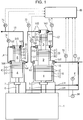
- a multi-stage compressor of one embodiment of the present invention will be described with reference to FIG. 1 .
- the multi-stage compressor includes a crank case 1, a plurality of (five in the present embodiment) compressing units 10 to 50, and a determining unit 60.
- each of the compressing units 10 to 50 compresses a hydrogen gas.
- the first compressing unit 10 includes a first cylinder 11 including a first compressing chamber 11S, a first piston 12, a first piston ring 13 provided on the first piston 12, a first suction valve Vs1 provided on a suction side of the first compressing chamber 11S, and a first discharge valve Vd1 provided on a discharge side of the first compressing chamber 11S.
- the first piston 12 is connected to a first rod 2 which is connected to a crankshaft (not shown) disposed in the crank case 1.
- a first distance piece 3 is provided in the first rod 2.
- the configurations of the second compressing unit 20 to the fifth compressing unit 50 are basically similar to the configuration of the first compressing unit 10. That is, the second compressing unit 20 includes a second cylinder 21 including a second compressing chamber 21S, a second piston 22, a second piston ring 23, a second suction valve Vs2, and a second discharge valve Vd2.
- the third compressing unit 30 includes a third cylinder 31 including a third compressing chamber 31S, a third piston 32, a third piston ring 33, a third suction valve Vs3, and a third discharge valve Vd3.
- the fourth compressing unit 40 includes a fourth cylinder 41 including a fourth compressing chamber 41S, a fourth piston 42, a fourth piston ring 43, a fourth suction valve Vs4, and a fourth discharge valve Vd4.
- the fifth compressing unit 50 includes a fifth cylinder 51 including a fifth compressing chamber 51S, a fifth piston 52, a fifth piston ring 53, a fifth suction valve Vs5, and a fifth discharge valve Vd5.
- the second piston 22 is connected to the first piston 12.
- the third piston 32 is connected to the second piston 22.
- the fourth piston 42 is connected to a second rod 6 which is connected to the crankshaft. A second distance piece 7 is provided in the second rod 6.
- the fifth piston 52 is connected to the fourth piston 42.
- a size of each of the cylinders 21 to 52 gradually decreases toward a high-pressure side (toward a fifth compressing unit 50 side). This also applies to a size of each of the pistons 22 to 52.
- the present embodiment includes a suction line L0, a first connecting line L1, a second connecting line L2, a third connecting line L3, a fourth connecting line L4, a discharge line L5, a first return line L11, and a second return line L41.
- the suction line L0 supplies a gas to the first compressing chamber 11S via the first suction valve Vs1.
- the first connecting line L1 guides the gas discharged from the first compressing chamber 11S via the first discharge valve Vd1 to the second compressing chamber 21S via the second suction valve Vs2.
- the second connecting line L2 guides the gas discharged from the second compressing chamber 21S via the second discharge valve Vd2 to the third compressing chamber 31S via the third suction valve Vs3.
- the third connecting line L3 guides the gas discharged from the third compressing chamber 31S via the third discharge valve Vd3 to the fourth compressing chamber 41S via the fourth suction valve Vs4.
- the fourth connecting line L4 guides the gas discharged from the fourth compressing chamber 41S via the fourth discharge valve Vd4 to the fifth compressing chamber 51S via the fifth suction valve Vs5.
- the discharge line L5 takes out the gas compressed by the fifth compressing chamber 51S to outside via the fifth discharge valve Vd5.
- the first return line L11 returns, to the suction line L0, the gas leaked from the first compressing chamber 11S to the crank case 1 side via a gap between the first cylinder 11 and the first piston ring 13.
- the second return line L41 returns, to the suction line L0, the gas leaked from the fourth compressing chamber 41S to the crank case 1 side via a gap between the fourth cylinder 41 and the fourth piston ring 43.
- the determining unit 60 determines whether a gas is leaking from each of the compressing units 10 to 50.
- detection of a gas leak resulting from deterioration of sealing performance of each of the suction valves Vs1 to Vs5 or each of the discharge valves Vd1 to Vd5, and detection of a gas leak resulting from wear of each of the piston rings 13, 23, 33, 43, and 53 will be described in this order.
- the determining unit 60 calculates the fifth proportion regularly, and when the calculated fifth proportion becomes equal to or less than a fifth set value, the determining unit 60 outputs a fifth signal indicating that a gas is leaking from the fifth compressing unit 50.
- the above description also applies to a case where the sealing performance of other valves deteriorates. That is, when a fourth proportion (proportion of discharge pressure from the fourth compressing unit 40 to suction pressure into the fourth compressing unit 40 or discharge pressure from the third compressing unit 40) becomes equal to or less than a fourth set value, the determining unit 60 outputs a fourth signal indicating that a gas is leaking from the fourth compressing unit 40.
- the determining unit 60 when a third proportion becomes equal to or less than a third set value, the determining unit 60 outputs a third signal indicating that a gas is leaking from the third compressing unit 30, when a second proportion becomes equal to or less than a second set value, the determining unit 60 outputs a second signal indicating that a gas is leaking from the second compressing unit 20, and when a first proportion becomes equal to or less than a first set value, the determining unit 60 outputs a first signal indicating that a gas is leaking from the first compressing unit 10.
- suction pressure into the first compressing unit 10 is detected by a pressure sensor 70 provided in the suction line L0.
- Discharge pressure from the first compressing unit 10 is detected by a pressure sensor 71 provided in the first connecting line L1.
- Discharge pressure from the second compressing unit 20 is detected by a pressure sensor 72 provided in the second connecting line L2.
- Discharge pressure from the third compressing unit 30 is detected by a pressure sensor 73 provided in the third connecting line L3.
- Discharge pressure from the fourth compressing unit 40 is detected by a pressure sensor 74 provided in the fourth connecting line L4.
- Discharge pressure from the fifth compressing unit 50 is detected by a pressure sensor 75 provided in the discharge line L5.
- the determining unit 60 outputs the fifth signal when the fifth proportion becomes equal to or less than the fifth set value.
- the determining unit 60 outputting the fifth signal, it is perceived that at least one of deterioration of the sealing performance of the fifth discharge valve Vd5 or the fifth suction valve Vs5, and wear of the fifth piston ring 53 occurs.
- the above description also applies to a case where wear occurs in the third piston ring 33 and the second piston ring 23. That is, by the determining unit 60 outputting the third signal, it is perceived that at least one of deterioration of the sealing performance of the third discharge valve Vd3 or the third suction valve Vs3, and wear of the third piston ring 33 occurs. Also, by the determining unit 60 outputting the second signal, it is perceived that at least one of deterioration of the sealing performance of the second discharge valve Vd2 or the second suction valve Vs2, and wear of the second piston ring 23 occurs.
- the determining unit 60 when wear occurs in the fourth piston ring 43, part of the gas in the fourth compressing chamber 41S flows into the suction line L0 through a gap between the fourth cylinder 41 and the fourth piston ring 43 and the second return line L41. At this time, a second temperature T2 of the second return line L41 rises. Therefore, when the second temperature T2 becomes equal to or higher than a second reference temperature T ⁇ , the determining unit 60 outputs a signal indicating that wear occurs in the fourth piston ring 43.
- the above description also applies to a case where wear occurs in the first piston ring 13. That is, when a first temperature T1 of the first return line L11 becomes equal to or higher than a first reference temperature T ⁇ , the determining unit 60 outputs a signal indicating that wear occurs in the first piston ring 13.
- the first temperature T1 is detected by a temperature sensor 81 provided in the first return line L11
- the second temperature T2 is detected by a temperature sensor 84 provided in the second return line L41.
- the multi-stage compressor of the present embodiment effectively detects that a gas is leaking from each of the compressing units 10 to 50.
- the embodiment shows an example in which when the third proportion becomes equal to or less than the third set value, the determining unit 60 outputs the third signal indicating that a gas is leaking from the third compressing unit 30.
- the determining unit 60 may output the third signal when the second proportion becomes greater than a predetermined value.
- FIG. 2 is a table showing suction pressure and discharge pressure in each of the compressing units 10 to 50 of the multi-stage compressor of the embodiment. Note that numerical values in this table are values when a gas is not leaking from each of the compressing units 10 to 50. In this example, the fifth proportion is 82/45.
- suction pressure into the fifth compressing unit 50 becomes 47 MPa, for example. Therefore, the fifth proportion changes to 82/47. Therefore, by setting the fifth set value, for example, at 82/46, detection of a gas leak from the fifth compressing unit 50 becomes possible.
- a gas leak determining method of the embodiment is a gas leak determining method for a multi-stage compressor including: a first compressing unit that compresses a gas; and a second compressing unit that further compresses the gas compressed by the first compressing unit, the gas leak determining method including: a step of calculating a proportion of discharge pressure from the second compressing unit to discharge pressure from the first compressing unit or suction pressure into the second compressing unit; and a step of determining that a gas is leaking from the second compressing unit when the proportion becomes equal to or less than a set value.
- This gas leak determining method effectively detects that a gas is leaking from the second compressing unit at higher pressure than the first compressing unit. Specifically, even if a negligible gas (amount of leak allowable from a design viewpoint) is leaking from the second compressing unit, the proportion is an almost constant value. However, when a gas leaks from the second compressing unit resulting from deterioration of sealing of the suction valve or the discharge valve in the second compressing unit, wear of the piston ring, or other reasons, discharge pressure from the first compressing unit (suction pressure into the second compressing unit) will rise, thereby decreasing the proportion. Therefore, it becomes possible to determine that, when the proportion becomes equal to or less than a threshold, a gas is leaking from the second compressing unit.
- a multi-stage compressor of the embodiment includes: a first compressing unit compressable a gas; a second compressing unit compressable the gas compressed by the first compressing unit; and a determining unit.
- the determining unit determines that a gas is leaking from the second compressing unit.
- This multi-stage compressor also effectively detects that a gas is leaking from the second compressing unit.
Landscapes
- Engineering & Computer Science (AREA)
- Mechanical Engineering (AREA)
- General Engineering & Computer Science (AREA)
- Computer Hardware Design (AREA)
- Control Of Positive-Displacement Pumps (AREA)
- Compressors, Vaccum Pumps And Other Relevant Systems (AREA)
- Compressor (AREA)
Abstract
Description
- The present invention relates to a gas leak determining method for a multi-stage compressor.
- Conventionally, reciprocating multi-stage compressors are known. For example,
Patent Literature 1 discloses a multi-stage compressor having five compressing units. Each compressing unit includes a cylinder having a compressing chamber, a piston, and a piston ring provided on the piston. A gas suctioned into a first compressing chamber of a first compressing unit is compressed in order from the first compressing unit, and is discharged from a fifth compressing unit. - In the multi-stage compressor described in
Patent Literature 1, a gas may leak from each compressing unit (gas may leak from a compressing chamber to a space lower than the compressing chamber in pressure), and there are needs for detecting this gas leak. - Patent Literature 1:
JP 2016-113907 A - An object of the present invention is to provide a multi-stage compressor that can detect a gas leak, and a gas leak determining method for the multi-stage compressor.
- A gas leak determining method according to one aspect of the present invention is a gas leak determining method for a multi-stage compressor including: a first compressing unit that compresses a gas; and a second compressing unit that further compresses the gas compressed by the first compressing unit, the gas leak determining method including: a step of calculating a proportion of discharge pressure from the second compressing unit to discharge pressure from the first compressing unit or suction pressure into the second compressing unit; and a step of determining that a gas is leaking from the second compressing unit when the proportion becomes equal to or less than a set value.
- A multi-stage compressor according to one aspect of the present invention includes: a first compressing unit compressable a gas; a second compressing unit compressable the gas compressed by the first compressing unit; and a determining unit, wherein the determining unit determines that a gas is leaking from the second compressing unit, when a proportion of discharge pressure from the second compressing unit to discharge pressure from the first compressing unit or suction pressure into the second compressing unit becomes equal to or less than a set value.
-
-
FIG. 1 is a diagram schematically showing a configuration of a multi-stage compressor of one embodiment of the present invention. -
FIG. 2 is a diagram showing an example of suction pressure and discharge pressure in each compressing unit of the multi-stage compressor shown inFIG. 1 . - A multi-stage compressor of one embodiment of the present invention will be described with reference to
FIG. 1 . - As shown in
FIG. 1 , the multi-stage compressor includes acrank case 1, a plurality of (five in the present embodiment) compressing units 10 to 50, and a determiningunit 60. In the present embodiment, each of the compressing units 10 to 50 compresses a hydrogen gas. - The first compressing unit 10 includes a first cylinder 11 including a first
compressing chamber 11S, afirst piston 12, afirst piston ring 13 provided on thefirst piston 12, a first suction valve Vs1 provided on a suction side of the firstcompressing chamber 11S, and a first discharge valve Vd1 provided on a discharge side of thefirst compressing chamber 11S. Thefirst piston 12 is connected to afirst rod 2 which is connected to a crankshaft (not shown) disposed in thecrank case 1. Afirst distance piece 3 is provided in thefirst rod 2. - The configurations of the second compressing
unit 20 to the fifth compressingunit 50 are basically similar to the configuration of the first compressing unit 10. That is, the secondcompressing unit 20 includes asecond cylinder 21 including a secondcompressing chamber 21S, asecond piston 22, asecond piston ring 23, a second suction valve Vs2, and a second discharge valve Vd2. The third compressingunit 30 includes athird cylinder 31 including a thirdcompressing chamber 31S, athird piston 32, athird piston ring 33, a third suction valve Vs3, and a third discharge valve Vd3. The fourthcompressing unit 40 includes afourth cylinder 41 including afourth compressing chamber 41S, afourth piston 42, afourth piston ring 43, a fourth suction valve Vs4, and a fourth discharge valve Vd4. The fifthcompressing unit 50 includes afifth cylinder 51 including a fifthcompressing chamber 51S, afifth piston 52, afifth piston ring 53, a fifth suction valve Vs5, and a fifth discharge valve Vd5. Thesecond piston 22 is connected to thefirst piston 12. Thethird piston 32 is connected to thesecond piston 22. Thefourth piston 42 is connected to asecond rod 6 which is connected to the crankshaft. Asecond distance piece 7 is provided in thesecond rod 6. Thefifth piston 52 is connected to thefourth piston 42. Note that a size of each of thecylinders 21 to 52 (each of thecompressing chambers 21S to 51S) gradually decreases toward a high-pressure side (toward a fifth compressingunit 50 side). This also applies to a size of each of thepistons 22 to 52. - The present embodiment includes a suction line L0, a first connecting line L1, a second connecting line L2, a third connecting line L3, a fourth connecting line L4, a discharge line L5, a first return line L11, and a second return line L41. The suction line L0 supplies a gas to the first
compressing chamber 11S via the first suction valve Vs1. The first connecting line L1 guides the gas discharged from the firstcompressing chamber 11S via the first discharge valve Vd1 to the secondcompressing chamber 21S via the second suction valve Vs2. The second connecting line L2 guides the gas discharged from the secondcompressing chamber 21S via the second discharge valve Vd2 to the thirdcompressing chamber 31S via the third suction valve Vs3. The third connecting line L3 guides the gas discharged from the thirdcompressing chamber 31S via the third discharge valve Vd3 to the fourthcompressing chamber 41S via the fourth suction valve Vs4. The fourth connecting line L4 guides the gas discharged from the fourthcompressing chamber 41S via the fourth discharge valve Vd4 to the fifthcompressing chamber 51S via the fifth suction valve Vs5. The discharge line L5 takes out the gas compressed by the fifth compressingchamber 51S to outside via the fifth discharge valve Vd5. The first return line L11 returns, to the suction line L0, the gas leaked from the firstcompressing chamber 11S to thecrank case 1 side via a gap between the first cylinder 11 and thefirst piston ring 13. The second return line L41 returns, to the suction line L0, the gas leaked from the fourthcompressing chamber 41S to thecrank case 1 side via a gap between thefourth cylinder 41 and thefourth piston ring 43. - The determining
unit 60 determines whether a gas is leaking from each of the compressing units 10 to 50. Hereinafter, detection of a gas leak resulting from deterioration of sealing performance of each of the suction valves Vs1 to Vs5 or each of the discharge valves Vd1 to Vd5, and detection of a gas leak resulting from wear of each of thepiston rings - For example, when the sealing performance of the fifth discharge valve Vd5 or the fifth suction valve Vs5 deteriorates, suction pressure into the fifth
compressing unit 50, that is, discharge pressure from the fourth compressingunit 40 rises. Therefore, by monitoring a proportion of discharge pressure from the fifth compressingunit 50 to the suction pressure into the fifth compressingunit 50 or the discharge pressure from the fourth compressing unit 40 (hereinafter referred to as "fifth proportion"), it becomes possible to detect deterioration of the sealing performance of the fifth discharge valve Vd5 or the fifth suction valve Vs5, that is, a gas leak from the fifth compressingunit 50. Specifically, when the sealing performance of the fifth discharge valve Vd5 or the fifth suction valve Vs5 deteriorates, the fifth proportion will decrease. Therefore, the determiningunit 60 calculates the fifth proportion regularly, and when the calculated fifth proportion becomes equal to or less than a fifth set value, the determiningunit 60 outputs a fifth signal indicating that a gas is leaking from the fifthcompressing unit 50. - The above description also applies to a case where the sealing performance of other valves deteriorates. That is, when a fourth proportion (proportion of discharge pressure from the fourth compressing
unit 40 to suction pressure into the fourth compressingunit 40 or discharge pressure from the third compressing unit 40) becomes equal to or less than a fourth set value, the determiningunit 60 outputs a fourth signal indicating that a gas is leaking from the fourth compressingunit 40. Hereinafter, similarly, when a third proportion becomes equal to or less than a third set value, the determiningunit 60 outputs a third signal indicating that a gas is leaking from the third compressingunit 30, when a second proportion becomes equal to or less than a second set value, the determiningunit 60 outputs a second signal indicating that a gas is leaking from the second compressingunit 20, and when a first proportion becomes equal to or less than a first set value, the determiningunit 60 outputs a first signal indicating that a gas is leaking from the first compressing unit 10. - Note that suction pressure into the first compressing unit 10 is detected by a
pressure sensor 70 provided in the suction line L0. Discharge pressure from the first compressing unit 10 (suction pressure into the second compressing unit 20) is detected by apressure sensor 71 provided in the first connecting line L1. Discharge pressure from the second compressing unit 20 (suction pressure into the third compressing unit 30) is detected by apressure sensor 72 provided in the second connecting line L2. Discharge pressure from the third compressing unit 30 (suction pressure into the fourth compressing unit 30) is detected by apressure sensor 73 provided in the third connecting line L3. Discharge pressure from the fourth compressing unit 40 (suction pressure into the fifth compressing unit 50) is detected by apressure sensor 74 provided in the fourth connecting line L4. Discharge pressure from the fifth compressingunit 50 is detected by apressure sensor 75 provided in the discharge line L5. - Next, detection when wear occurs in each of the
piston rings 13 to 53 will be described. - For example, when wear occurs in the
fifth piston ring 53, part of the gas in the fifth compressingchamber 51S flows into the fourthcompressing chamber 41S through a gap between thefifth cylinder 51 and thefifth piston ring 53, leading to a rise in suction pressure into the fifth compressingunit 50, that is, discharge pressure from the fourth compressingunit 40. Therefore, in a similar manner to a case where the sealing performance of the fifth discharge valve Vd5 or the fifth suction valve Vs5 deteriorates, the determiningunit 60 outputs the fifth signal when the fifth proportion becomes equal to or less than the fifth set value. That is, in the present embodiment, by the determiningunit 60 outputting the fifth signal, it is perceived that at least one of deterioration of the sealing performance of the fifth discharge valve Vd5 or the fifth suction valve Vs5, and wear of thefifth piston ring 53 occurs. - The above description also applies to a case where wear occurs in the
third piston ring 33 and thesecond piston ring 23. That is, by the determiningunit 60 outputting the third signal, it is perceived that at least one of deterioration of the sealing performance of the third discharge valve Vd3 or the third suction valve Vs3, and wear of thethird piston ring 33 occurs. Also, by the determiningunit 60 outputting the second signal, it is perceived that at least one of deterioration of the sealing performance of the second discharge valve Vd2 or the second suction valve Vs2, and wear of thesecond piston ring 23 occurs. - Meanwhile, in the present embodiment, when wear occurs in the
fourth piston ring 43, part of the gas in thefourth compressing chamber 41S flows into the suction line L0 through a gap between thefourth cylinder 41 and thefourth piston ring 43 and the second return line L41. At this time, a second temperature T2 of the second return line L41 rises. Therefore, when the second temperature T2 becomes equal to or higher than a second reference temperature Tβ, the determiningunit 60 outputs a signal indicating that wear occurs in thefourth piston ring 43. The above description also applies to a case where wear occurs in thefirst piston ring 13. That is, when a first temperature T1 of the first return line L11 becomes equal to or higher than a first reference temperature Tα, the determiningunit 60 outputs a signal indicating that wear occurs in thefirst piston ring 13. - Note that the first temperature T1 is detected by a
temperature sensor 81 provided in the first return line L11, and the second temperature T2 is detected by atemperature sensor 84 provided in the second return line L41. - As described above, the multi-stage compressor of the present embodiment effectively detects that a gas is leaking from each of the compressing units 10 to 50.
- It should be appreciated that the embodiment disclosed this time is in all aspects illustrative and not restrictive. The scope of the present invention is indicated by the appended claims rather than by the foregoing description, and all changes which come within the meaning and scope of the claims and equivalents are therefore intended to be embraced therein.
- For example, the embodiment shows an example in which when the third proportion becomes equal to or less than the third set value, the determining
unit 60 outputs the third signal indicating that a gas is leaking from thethird compressing unit 30. However, the determiningunit 60 may output the third signal when the second proportion becomes greater than a predetermined value. -
FIG. 2 is a table showing suction pressure and discharge pressure in each of the compressing units 10 to 50 of the multi-stage compressor of the embodiment. Note that numerical values in this table are values when a gas is not leaking from each of the compressing units 10 to 50. In this example, the fifth proportion is 82/45. - Here, when a gas leaks from the
fifth compressing unit 50, suction pressure into the fifth compressing unit 50 (discharge pressure from the fourth compressing unit 40) becomes 47 MPa, for example. Therefore, the fifth proportion changes to 82/47. Therefore, by setting the fifth set value, for example, at 82/46, detection of a gas leak from thefifth compressing unit 50 becomes possible. - Here, the embodiment will be outlined.
- A gas leak determining method of the embodiment is a gas leak determining method for a multi-stage compressor including: a first compressing unit that compresses a gas; and a second compressing unit that further compresses the gas compressed by the first compressing unit, the gas leak determining method including: a step of calculating a proportion of discharge pressure from the second compressing unit to discharge pressure from the first compressing unit or suction pressure into the second compressing unit; and a step of determining that a gas is leaking from the second compressing unit when the proportion becomes equal to or less than a set value.
- This gas leak determining method effectively detects that a gas is leaking from the second compressing unit at higher pressure than the first compressing unit. Specifically, even if a negligible gas (amount of leak allowable from a design viewpoint) is leaking from the second compressing unit, the proportion is an almost constant value. However, when a gas leaks from the second compressing unit resulting from deterioration of sealing of the suction valve or the discharge valve in the second compressing unit, wear of the piston ring, or other reasons, discharge pressure from the first compressing unit (suction pressure into the second compressing unit) will rise, thereby decreasing the proportion. Therefore, it becomes possible to determine that, when the proportion becomes equal to or less than a threshold, a gas is leaking from the second compressing unit.
- Meanwhile, a multi-stage compressor of the embodiment includes: a first compressing unit compressable a gas; a second compressing unit compressable the gas compressed by the first compressing unit; and a determining unit. When a proportion of discharge pressure from the second compressing unit to discharge pressure from the first compressing unit or suction pressure into the second compressing unit becomes equal to or less than a set value, the determining unit determines that a gas is leaking from the second compressing unit.
- This multi-stage compressor also effectively detects that a gas is leaking from the second compressing unit.
Claims (2)
- A gas leak determining method for a multi-stage compressor including:a first compressing unit that compresses a gas; anda second compressing unit that further compresses the gas compressed by the first compressing unit,the gas leak determining method comprising:a step of calculating a proportion of discharge pressure from the second compressing unit to discharge pressure from the first compressing unit or suction pressure into the second compressing unit; anda step of determining that a gas is leaking from the second compressing unit when the proportion becomes equal to or less than a set value.
- A multi-stage compressor comprising:a first compressing unit compressable a gas;a second compressing unit compressable the gas compressed by the first compressing unit; anda determining unit,wherein the determining unit determines that a gas is leaking from the second compressing unit, when a proportion of discharge pressure from the second compressing unit to discharge pressure from the first compressing unit or suction pressure into the second compressing unit becomes equal to or less than a set value.
Applications Claiming Priority (2)
| Application Number | Priority Date | Filing Date | Title |
|---|---|---|---|
| JP2016146562A JP6698461B2 (en) | 2016-07-26 | 2016-07-26 | Gas leak determination method and multi-stage compressor |
| PCT/JP2017/023384 WO2018020925A1 (en) | 2016-07-26 | 2017-06-26 | Gas leak determining method, and multi-stage compressor |
Publications (3)
| Publication Number | Publication Date |
|---|---|
| EP3462029A1 true EP3462029A1 (en) | 2019-04-03 |
| EP3462029A4 EP3462029A4 (en) | 2019-04-17 |
| EP3462029B1 EP3462029B1 (en) | 2021-03-10 |
Family
ID=61015969
Family Applications (1)
| Application Number | Title | Priority Date | Filing Date |
|---|---|---|---|
| EP17833934.7A Not-in-force EP3462029B1 (en) | 2016-07-26 | 2017-06-26 | Gas leak determining method, and multi-stage compressor |
Country Status (5)
| Country | Link |
|---|---|
| US (1) | US11085430B2 (en) |
| EP (1) | EP3462029B1 (en) |
| JP (1) | JP6698461B2 (en) |
| CN (1) | CN109477480B (en) |
| WO (1) | WO2018020925A1 (en) |
Families Citing this family (7)
| Publication number | Priority date | Publication date | Assignee | Title |
|---|---|---|---|---|
| AU2018204532B1 (en) * | 2017-11-06 | 2019-06-13 | Quantum Servo Pumping Technologies Pty Ltd | Fault detection and prediction |
| JP6889652B2 (en) * | 2017-11-20 | 2021-06-18 | 株式会社神戸製鋼所 | Compressor |
| US11181103B2 (en) * | 2018-06-19 | 2021-11-23 | Waters Technologies Corporation | Multi-stage displacement pump |
| KR102142940B1 (en) * | 2019-04-09 | 2020-08-11 | 가부시키가이샤 고베 세이코쇼 | Compressor unit and stopping method of compressor unit |
| JP6625783B1 (en) * | 2019-08-23 | 2019-12-25 | 株式会社神戸製鋼所 | Compressor unit |
| US11346348B2 (en) * | 2019-09-04 | 2022-05-31 | Advanced Flow Solutions, Inc. | Liquefied gas unloading and deep evacuation system |
| JP7857109B2 (en) | 2022-02-09 | 2026-05-12 | 株式会社神戸製鋼所 | Reciprocating compressor |
Family Cites Families (11)
| Publication number | Priority date | Publication date | Assignee | Title |
|---|---|---|---|---|
| DE1195427B (en) * | 1961-07-05 | 1965-06-24 | Basf Ag | Three-stage high pressure gas compressor with a piston seal |
| JPS5847187A (en) * | 1981-09-12 | 1983-03-18 | Mikuni Jukogyo Kk | Apparatus for controlling operation of multiple stage gas compressor |
| JPS623975U (en) * | 1985-06-21 | 1987-01-10 | ||
| JPH089992B2 (en) * | 1990-06-19 | 1996-01-31 | トキコ株式会社 | Multi-stage compressor |
| US5863186A (en) * | 1996-10-15 | 1999-01-26 | Green; John S. | Method for compressing gases using a multi-stage hydraulically-driven compressor |
| JP2002371960A (en) * | 2001-06-14 | 2002-12-26 | Toshiba Eng Co Ltd | Gas compression equipment |
| JP2006178712A (en) * | 2004-12-22 | 2006-07-06 | Hitachi Industries Co Ltd | Self-diagnosis method for equipment and screw compressor using the same |
| US20100054958A1 (en) * | 2006-09-05 | 2010-03-04 | New York Air Brake Corporation | Oil-free air compressor system with inlet throttle |
| JP2011007098A (en) * | 2009-06-25 | 2011-01-13 | Honda Motor Co Ltd | Compression device and failure determination method of compression device |
| US20130280095A1 (en) * | 2012-04-20 | 2013-10-24 | General Electric Company | Method and system for reciprocating compressor starting |
| JP6363488B2 (en) * | 2014-12-11 | 2018-07-25 | 株式会社神戸製鋼所 | Compressor |
-
2016
- 2016-07-26 JP JP2016146562A patent/JP6698461B2/en active Active
-
2017
- 2017-06-26 WO PCT/JP2017/023384 patent/WO2018020925A1/en not_active Ceased
- 2017-06-26 CN CN201780040256.7A patent/CN109477480B/en not_active Expired - Fee Related
- 2017-06-26 US US16/312,237 patent/US11085430B2/en active Active
- 2017-06-26 EP EP17833934.7A patent/EP3462029B1/en not_active Not-in-force
Also Published As
| Publication number | Publication date |
|---|---|
| WO2018020925A1 (en) | 2018-02-01 |
| US11085430B2 (en) | 2021-08-10 |
| JP6698461B2 (en) | 2020-05-27 |
| US20190331103A1 (en) | 2019-10-31 |
| CN109477480B (en) | 2020-07-14 |
| CN109477480A (en) | 2019-03-15 |
| EP3462029A4 (en) | 2019-04-17 |
| EP3462029B1 (en) | 2021-03-10 |
| JP2018017145A (en) | 2018-02-01 |
Similar Documents
| Publication | Publication Date | Title |
|---|---|---|
| US11085430B2 (en) | Gas leak determining method, and multi-stage compressor | |
| KR101656558B1 (en) | Gas compressor and abrasion state determining method | |
| KR102901788B1 (en) | Method and device for monitoring the condition of a piston rod sealing system of a piston compressor | |
| EP3225845B1 (en) | Compressor | |
| CN107917069B (en) | Reciprocating compressor flow sensing | |
| US20250382959A1 (en) | Packing case with degradation monitoring | |
| US11754067B2 (en) | Fault detection and prediction | |
| KR101843847B1 (en) | Nitrogen gas pressure monitoring system of Intake and exhaust valve actuation device for very large engine | |
| JP5695583B2 (en) | Fault diagnosis device for hydraulic pump | |
| JP7001538B2 (en) | Fluid leak detection system | |
| CN115681115B (en) | Method and device for detecting faults of reciprocating compressor | |
| EP4621228A1 (en) | Leakage monitoring for booster pump | |
| JP2002242842A (en) | Diaphragm pump | |
| KR102607296B1 (en) | Diaphragm compressor | |
| US20230250812A1 (en) | Reciprocating compressor |
Legal Events
| Date | Code | Title | Description |
|---|---|---|---|
| STAA | Information on the status of an ep patent application or granted ep patent |
Free format text: STATUS: THE INTERNATIONAL PUBLICATION HAS BEEN MADE |
|
| PUAI | Public reference made under article 153(3) epc to a published international application that has entered the european phase |
Free format text: ORIGINAL CODE: 0009012 |
|
| STAA | Information on the status of an ep patent application or granted ep patent |
Free format text: STATUS: REQUEST FOR EXAMINATION WAS MADE |
|
| 17P | Request for examination filed |
Effective date: 20181227 |
|
| AK | Designated contracting states |
Kind code of ref document: A1 Designated state(s): AL AT BE BG CH CY CZ DE DK EE ES FI FR GB GR HR HU IE IS IT LI LT LU LV MC MK MT NL NO PL PT RO RS SE SI SK SM TR |
|
| AX | Request for extension of the european patent |
Extension state: BA ME |
|
| A4 | Supplementary search report drawn up and despatched |
Effective date: 20190319 |
|
| RIC1 | Information provided on ipc code assigned before grant |
Ipc: F04B 25/02 20060101ALI20190313BHEP Ipc: F04B 49/10 20060101AFI20190313BHEP Ipc: F04B 49/06 20060101ALI20190313BHEP |
|
| DAV | Request for validation of the european patent (deleted) | ||
| DAX | Request for extension of the european patent (deleted) | ||
| GRAP | Despatch of communication of intention to grant a patent |
Free format text: ORIGINAL CODE: EPIDOSNIGR1 |
|
| STAA | Information on the status of an ep patent application or granted ep patent |
Free format text: STATUS: GRANT OF PATENT IS INTENDED |
|
| INTG | Intention to grant announced |
Effective date: 20201204 |
|
| GRAS | Grant fee paid |
Free format text: ORIGINAL CODE: EPIDOSNIGR3 |
|
| GRAA | (expected) grant |
Free format text: ORIGINAL CODE: 0009210 |
|
| STAA | Information on the status of an ep patent application or granted ep patent |
Free format text: STATUS: THE PATENT HAS BEEN GRANTED |
|
| AK | Designated contracting states |
Kind code of ref document: B1 Designated state(s): AL AT BE BG CH CY CZ DE DK EE ES FI FR GB GR HR HU IE IS IT LI LT LU LV MC MK MT NL NO PL PT RO RS SE SI SK SM TR |
|
| REG | Reference to a national code |
Ref country code: GB Ref legal event code: FG4D |
|
| REG | Reference to a national code |
Ref country code: AT Ref legal event code: REF Ref document number: 1370092 Country of ref document: AT Kind code of ref document: T Effective date: 20210315 Ref country code: CH Ref legal event code: EP |
|
| REG | Reference to a national code |
Ref country code: DE Ref legal event code: R096 Ref document number: 602017034506 Country of ref document: DE |
|
| REG | Reference to a national code |
Ref country code: IE Ref legal event code: FG4D |
|
| REG | Reference to a national code |
Ref country code: LT Ref legal event code: MG9D |
|
| PG25 | Lapsed in a contracting state [announced via postgrant information from national office to epo] |
Ref country code: HR Free format text: LAPSE BECAUSE OF FAILURE TO SUBMIT A TRANSLATION OF THE DESCRIPTION OR TO PAY THE FEE WITHIN THE PRESCRIBED TIME-LIMIT Effective date: 20210310 Ref country code: FI Free format text: LAPSE BECAUSE OF FAILURE TO SUBMIT A TRANSLATION OF THE DESCRIPTION OR TO PAY THE FEE WITHIN THE PRESCRIBED TIME-LIMIT Effective date: 20210310 Ref country code: GR Free format text: LAPSE BECAUSE OF FAILURE TO SUBMIT A TRANSLATION OF THE DESCRIPTION OR TO PAY THE FEE WITHIN THE PRESCRIBED TIME-LIMIT Effective date: 20210611 Ref country code: NO Free format text: LAPSE BECAUSE OF FAILURE TO SUBMIT A TRANSLATION OF THE DESCRIPTION OR TO PAY THE FEE WITHIN THE PRESCRIBED TIME-LIMIT Effective date: 20210610 Ref country code: BG Free format text: LAPSE BECAUSE OF FAILURE TO SUBMIT A TRANSLATION OF THE DESCRIPTION OR TO PAY THE FEE WITHIN THE PRESCRIBED TIME-LIMIT Effective date: 20210610 Ref country code: LT Free format text: LAPSE BECAUSE OF FAILURE TO SUBMIT A TRANSLATION OF THE DESCRIPTION OR TO PAY THE FEE WITHIN THE PRESCRIBED TIME-LIMIT Effective date: 20210310 |
|
| REG | Reference to a national code |
Ref country code: AT Ref legal event code: MK05 Ref document number: 1370092 Country of ref document: AT Kind code of ref document: T Effective date: 20210310 |
|
| REG | Reference to a national code |
Ref country code: NL Ref legal event code: MP Effective date: 20210310 |
|
| PG25 | Lapsed in a contracting state [announced via postgrant information from national office to epo] |
Ref country code: RS Free format text: LAPSE BECAUSE OF FAILURE TO SUBMIT A TRANSLATION OF THE DESCRIPTION OR TO PAY THE FEE WITHIN THE PRESCRIBED TIME-LIMIT Effective date: 20210310 Ref country code: LV Free format text: LAPSE BECAUSE OF FAILURE TO SUBMIT A TRANSLATION OF THE DESCRIPTION OR TO PAY THE FEE WITHIN THE PRESCRIBED TIME-LIMIT Effective date: 20210310 Ref country code: SE Free format text: LAPSE BECAUSE OF FAILURE TO SUBMIT A TRANSLATION OF THE DESCRIPTION OR TO PAY THE FEE WITHIN THE PRESCRIBED TIME-LIMIT Effective date: 20210310 |
|
| PG25 | Lapsed in a contracting state [announced via postgrant information from national office to epo] |
Ref country code: NL Free format text: LAPSE BECAUSE OF FAILURE TO SUBMIT A TRANSLATION OF THE DESCRIPTION OR TO PAY THE FEE WITHIN THE PRESCRIBED TIME-LIMIT Effective date: 20210310 |
|
| PG25 | Lapsed in a contracting state [announced via postgrant information from national office to epo] |
Ref country code: SM Free format text: LAPSE BECAUSE OF FAILURE TO SUBMIT A TRANSLATION OF THE DESCRIPTION OR TO PAY THE FEE WITHIN THE PRESCRIBED TIME-LIMIT Effective date: 20210310 Ref country code: AT Free format text: LAPSE BECAUSE OF FAILURE TO SUBMIT A TRANSLATION OF THE DESCRIPTION OR TO PAY THE FEE WITHIN THE PRESCRIBED TIME-LIMIT Effective date: 20210310 Ref country code: CZ Free format text: LAPSE BECAUSE OF FAILURE TO SUBMIT A TRANSLATION OF THE DESCRIPTION OR TO PAY THE FEE WITHIN THE PRESCRIBED TIME-LIMIT Effective date: 20210310 Ref country code: EE Free format text: LAPSE BECAUSE OF FAILURE TO SUBMIT A TRANSLATION OF THE DESCRIPTION OR TO PAY THE FEE WITHIN THE PRESCRIBED TIME-LIMIT Effective date: 20210310 |
|
| PG25 | Lapsed in a contracting state [announced via postgrant information from national office to epo] |
Ref country code: IS Free format text: LAPSE BECAUSE OF FAILURE TO SUBMIT A TRANSLATION OF THE DESCRIPTION OR TO PAY THE FEE WITHIN THE PRESCRIBED TIME-LIMIT Effective date: 20210710 Ref country code: PT Free format text: LAPSE BECAUSE OF FAILURE TO SUBMIT A TRANSLATION OF THE DESCRIPTION OR TO PAY THE FEE WITHIN THE PRESCRIBED TIME-LIMIT Effective date: 20210712 Ref country code: PL Free format text: LAPSE BECAUSE OF FAILURE TO SUBMIT A TRANSLATION OF THE DESCRIPTION OR TO PAY THE FEE WITHIN THE PRESCRIBED TIME-LIMIT Effective date: 20210310 Ref country code: RO Free format text: LAPSE BECAUSE OF FAILURE TO SUBMIT A TRANSLATION OF THE DESCRIPTION OR TO PAY THE FEE WITHIN THE PRESCRIBED TIME-LIMIT Effective date: 20210310 Ref country code: SK Free format text: LAPSE BECAUSE OF FAILURE TO SUBMIT A TRANSLATION OF THE DESCRIPTION OR TO PAY THE FEE WITHIN THE PRESCRIBED TIME-LIMIT Effective date: 20210310 |
|
| REG | Reference to a national code |
Ref country code: DE Ref legal event code: R097 Ref document number: 602017034506 Country of ref document: DE |
|
| PLBE | No opposition filed within time limit |
Free format text: ORIGINAL CODE: 0009261 |
|
| STAA | Information on the status of an ep patent application or granted ep patent |
Free format text: STATUS: NO OPPOSITION FILED WITHIN TIME LIMIT |
|
| PG25 | Lapsed in a contracting state [announced via postgrant information from national office to epo] |
Ref country code: AL Free format text: LAPSE BECAUSE OF FAILURE TO SUBMIT A TRANSLATION OF THE DESCRIPTION OR TO PAY THE FEE WITHIN THE PRESCRIBED TIME-LIMIT Effective date: 20210310 Ref country code: DK Free format text: LAPSE BECAUSE OF FAILURE TO SUBMIT A TRANSLATION OF THE DESCRIPTION OR TO PAY THE FEE WITHIN THE PRESCRIBED TIME-LIMIT Effective date: 20210310 Ref country code: MC Free format text: LAPSE BECAUSE OF FAILURE TO SUBMIT A TRANSLATION OF THE DESCRIPTION OR TO PAY THE FEE WITHIN THE PRESCRIBED TIME-LIMIT Effective date: 20210310 Ref country code: ES Free format text: LAPSE BECAUSE OF FAILURE TO SUBMIT A TRANSLATION OF THE DESCRIPTION OR TO PAY THE FEE WITHIN THE PRESCRIBED TIME-LIMIT Effective date: 20210310 |
|
| REG | Reference to a national code |
Ref country code: CH Ref legal event code: PL |
|
| 26N | No opposition filed |
Effective date: 20211213 |
|
| GBPC | Gb: european patent ceased through non-payment of renewal fee |
Effective date: 20210626 |
|
| PG25 | Lapsed in a contracting state [announced via postgrant information from national office to epo] |
Ref country code: SI Free format text: LAPSE BECAUSE OF FAILURE TO SUBMIT A TRANSLATION OF THE DESCRIPTION OR TO PAY THE FEE WITHIN THE PRESCRIBED TIME-LIMIT Effective date: 20210310 |
|
| REG | Reference to a national code |
Ref country code: BE Ref legal event code: MM Effective date: 20210630 |
|
| PG25 | Lapsed in a contracting state [announced via postgrant information from national office to epo] |
Ref country code: LU Free format text: LAPSE BECAUSE OF NON-PAYMENT OF DUE FEES Effective date: 20210626 |
|
| PG25 | Lapsed in a contracting state [announced via postgrant information from national office to epo] |
Ref country code: LI Free format text: LAPSE BECAUSE OF NON-PAYMENT OF DUE FEES Effective date: 20210630 Ref country code: IT Free format text: LAPSE BECAUSE OF FAILURE TO SUBMIT A TRANSLATION OF THE DESCRIPTION OR TO PAY THE FEE WITHIN THE PRESCRIBED TIME-LIMIT Effective date: 20210310 Ref country code: IE Free format text: LAPSE BECAUSE OF NON-PAYMENT OF DUE FEES Effective date: 20210626 Ref country code: GB Free format text: LAPSE BECAUSE OF NON-PAYMENT OF DUE FEES Effective date: 20210626 Ref country code: CH Free format text: LAPSE BECAUSE OF NON-PAYMENT OF DUE FEES Effective date: 20210630 |
|
| PG25 | Lapsed in a contracting state [announced via postgrant information from national office to epo] |
Ref country code: IS Free format text: LAPSE BECAUSE OF FAILURE TO SUBMIT A TRANSLATION OF THE DESCRIPTION OR TO PAY THE FEE WITHIN THE PRESCRIBED TIME-LIMIT Effective date: 20210710 |
|
| PG25 | Lapsed in a contracting state [announced via postgrant information from national office to epo] |
Ref country code: BE Free format text: LAPSE BECAUSE OF NON-PAYMENT OF DUE FEES Effective date: 20210630 |
|
| P01 | Opt-out of the competence of the unified patent court (upc) registered |
Effective date: 20230523 |
|
| PG25 | Lapsed in a contracting state [announced via postgrant information from national office to epo] |
Ref country code: CY Free format text: LAPSE BECAUSE OF FAILURE TO SUBMIT A TRANSLATION OF THE DESCRIPTION OR TO PAY THE FEE WITHIN THE PRESCRIBED TIME-LIMIT Effective date: 20210310 |
|
| PG25 | Lapsed in a contracting state [announced via postgrant information from national office to epo] |
Ref country code: HU Free format text: LAPSE BECAUSE OF FAILURE TO SUBMIT A TRANSLATION OF THE DESCRIPTION OR TO PAY THE FEE WITHIN THE PRESCRIBED TIME-LIMIT; INVALID AB INITIO Effective date: 20170626 |
|
| PGFP | Annual fee paid to national office [announced via postgrant information from national office to epo] |
Ref country code: FR Payment date: 20230510 Year of fee payment: 7 Ref country code: DE Payment date: 20230502 Year of fee payment: 7 |
|
| PG25 | Lapsed in a contracting state [announced via postgrant information from national office to epo] |
Ref country code: MK Free format text: LAPSE BECAUSE OF FAILURE TO SUBMIT A TRANSLATION OF THE DESCRIPTION OR TO PAY THE FEE WITHIN THE PRESCRIBED TIME-LIMIT Effective date: 20210310 |
|
| PG25 | Lapsed in a contracting state [announced via postgrant information from national office to epo] |
Ref country code: MT Free format text: LAPSE BECAUSE OF FAILURE TO SUBMIT A TRANSLATION OF THE DESCRIPTION OR TO PAY THE FEE WITHIN THE PRESCRIBED TIME-LIMIT Effective date: 20210310 |
|
| REG | Reference to a national code |
Ref country code: DE Ref legal event code: R119 Ref document number: 602017034506 Country of ref document: DE |
|
| PG25 | Lapsed in a contracting state [announced via postgrant information from national office to epo] |
Ref country code: DE Free format text: LAPSE BECAUSE OF NON-PAYMENT OF DUE FEES Effective date: 20250101 |
|
| PG25 | Lapsed in a contracting state [announced via postgrant information from national office to epo] |
Ref country code: FR Free format text: LAPSE BECAUSE OF NON-PAYMENT OF DUE FEES Effective date: 20240630 |
|
| PG25 | Lapsed in a contracting state [announced via postgrant information from national office to epo] |
Ref country code: TR Free format text: LAPSE BECAUSE OF FAILURE TO SUBMIT A TRANSLATION OF THE DESCRIPTION OR TO PAY THE FEE WITHIN THE PRESCRIBED TIME-LIMIT Effective date: 20210310 |