EP3462018A1 - Methods for adapting wind farms for grid compliance - Google Patents
Methods for adapting wind farms for grid compliance Download PDFInfo
- Publication number
- EP3462018A1 EP3462018A1 EP18196039.4A EP18196039A EP3462018A1 EP 3462018 A1 EP3462018 A1 EP 3462018A1 EP 18196039 A EP18196039 A EP 18196039A EP 3462018 A1 EP3462018 A1 EP 3462018A1
- Authority
- EP
- European Patent Office
- Prior art keywords
- farm
- wind
- wind turbines
- upgraded
- level controller
- Prior art date
- Legal status (The legal status is an assumption and is not a legal conclusion. Google has not performed a legal analysis and makes no representation as to the accuracy of the status listed.)
- Granted
Links
Images


Classifications
-
- F—MECHANICAL ENGINEERING; LIGHTING; HEATING; WEAPONS; BLASTING
- F03—MACHINES OR ENGINES FOR LIQUIDS; WIND, SPRING, OR WEIGHT MOTORS; PRODUCING MECHANICAL POWER OR A REACTIVE PROPULSIVE THRUST, NOT OTHERWISE PROVIDED FOR
- F03D—WIND MOTORS
- F03D7/00—Controlling wind motors
- F03D7/02—Controlling wind motors the wind motors having rotation axis substantially parallel to the air flow entering the rotor
- F03D7/028—Controlling wind motors the wind motors having rotation axis substantially parallel to the air flow entering the rotor controlling wind motor output power
- F03D7/0284—Controlling wind motors the wind motors having rotation axis substantially parallel to the air flow entering the rotor controlling wind motor output power in relation to the state of the electric grid
-
- F—MECHANICAL ENGINEERING; LIGHTING; HEATING; WEAPONS; BLASTING
- F03—MACHINES OR ENGINES FOR LIQUIDS; WIND, SPRING, OR WEIGHT MOTORS; PRODUCING MECHANICAL POWER OR A REACTIVE PROPULSIVE THRUST, NOT OTHERWISE PROVIDED FOR
- F03D—WIND MOTORS
- F03D17/00—Monitoring or testing of wind motors, e.g. diagnostics
-
- F—MECHANICAL ENGINEERING; LIGHTING; HEATING; WEAPONS; BLASTING
- F03—MACHINES OR ENGINES FOR LIQUIDS; WIND, SPRING, OR WEIGHT MOTORS; PRODUCING MECHANICAL POWER OR A REACTIVE PROPULSIVE THRUST, NOT OTHERWISE PROVIDED FOR
- F03D—WIND MOTORS
- F03D7/00—Controlling wind motors
- F03D7/02—Controlling wind motors the wind motors having rotation axis substantially parallel to the air flow entering the rotor
- F03D7/04—Automatic control; Regulation
- F03D7/042—Automatic control; Regulation by means of an electrical or electronic controller
- F03D7/048—Automatic control; Regulation by means of an electrical or electronic controller controlling wind farms
-
- F—MECHANICAL ENGINEERING; LIGHTING; HEATING; WEAPONS; BLASTING
- F03—MACHINES OR ENGINES FOR LIQUIDS; WIND, SPRING, OR WEIGHT MOTORS; PRODUCING MECHANICAL POWER OR A REACTIVE PROPULSIVE THRUST, NOT OTHERWISE PROVIDED FOR
- F03D—WIND MOTORS
- F03D80/00—Details, components or accessories not provided for in groups F03D1/00 - F03D17/00
- F03D80/50—Maintenance or repair
-
- F—MECHANICAL ENGINEERING; LIGHTING; HEATING; WEAPONS; BLASTING
- F03—MACHINES OR ENGINES FOR LIQUIDS; WIND, SPRING, OR WEIGHT MOTORS; PRODUCING MECHANICAL POWER OR A REACTIVE PROPULSIVE THRUST, NOT OTHERWISE PROVIDED FOR
- F03D—WIND MOTORS
- F03D9/00—Adaptations of wind motors for special use; Combinations of wind motors with apparatus driven thereby; Wind motors specially adapted for installation in particular locations
- F03D9/20—Wind motors characterised by the driven apparatus
- F03D9/25—Wind motors characterised by the driven apparatus the apparatus being an electrical generator
- F03D9/255—Wind motors characterised by the driven apparatus the apparatus being an electrical generator connected to electrical distribution networks; Arrangements therefor
- F03D9/257—Wind motors characterised by the driven apparatus the apparatus being an electrical generator connected to electrical distribution networks; Arrangements therefor the wind motor being part of a wind farm
-
- H—ELECTRICITY
- H02—GENERATION; CONVERSION OR DISTRIBUTION OF ELECTRIC POWER
- H02J—CIRCUIT ARRANGEMENTS OR SYSTEMS FOR SUPPLYING OR DISTRIBUTING ELECTRIC POWER; SYSTEMS FOR STORING ELECTRIC ENERGY
- H02J3/00—Circuit arrangements for AC mains or AC distribution networks
- H02J3/38—Arrangements for parallely feeding a single network by two or more generators, converters or transformers
- H02J3/381—Dispersed generators
-
- F—MECHANICAL ENGINEERING; LIGHTING; HEATING; WEAPONS; BLASTING
- F05—INDEXING SCHEMES RELATING TO ENGINES OR PUMPS IN VARIOUS SUBCLASSES OF CLASSES F01-F04
- F05B—INDEXING SCHEME RELATING TO WIND, SPRING, WEIGHT, INERTIA OR LIKE MOTORS, TO MACHINES OR ENGINES FOR LIQUIDS COVERED BY SUBCLASSES F03B, F03D AND F03G
- F05B2230/00—Manufacture
- F05B2230/80—Repairing, retrofitting or upgrading methods
-
- H02J2101/28—
-
- H—ELECTRICITY
- H02—GENERATION; CONVERSION OR DISTRIBUTION OF ELECTRIC POWER
- H02M—APPARATUS FOR CONVERSION BETWEEN AC AND AC, BETWEEN AC AND DC, OR BETWEEN DC AND DC, AND FOR USE WITH MAINS OR SIMILAR POWER SUPPLY SYSTEMS; CONVERSION OF DC OR AC INPUT POWER INTO SURGE OUTPUT POWER; CONTROL OR REGULATION THEREOF
- H02M5/00—Conversion of AC power input into AC power output, e.g. for change of voltage, for change of frequency, for change of number of phases
- H02M5/40—Conversion of AC power input into AC power output, e.g. for change of voltage, for change of frequency, for change of number of phases with intermediate conversion into DC
- H02M5/42—Conversion of AC power input into AC power output, e.g. for change of voltage, for change of frequency, for change of number of phases with intermediate conversion into DC by static converters
-
- Y—GENERAL TAGGING OF NEW TECHNOLOGICAL DEVELOPMENTS; GENERAL TAGGING OF CROSS-SECTIONAL TECHNOLOGIES SPANNING OVER SEVERAL SECTIONS OF THE IPC; TECHNICAL SUBJECTS COVERED BY FORMER USPC CROSS-REFERENCE ART COLLECTIONS [XRACs] AND DIGESTS
- Y02—TECHNOLOGIES OR APPLICATIONS FOR MITIGATION OR ADAPTATION AGAINST CLIMATE CHANGE
- Y02E—REDUCTION OF GREENHOUSE GAS [GHG] EMISSIONS, RELATED TO ENERGY GENERATION, TRANSMISSION OR DISTRIBUTION
- Y02E10/00—Energy generation through renewable energy sources
- Y02E10/70—Wind energy
- Y02E10/72—Wind turbines with rotation axis in wind direction
-
- Y—GENERAL TAGGING OF NEW TECHNOLOGICAL DEVELOPMENTS; GENERAL TAGGING OF CROSS-SECTIONAL TECHNOLOGIES SPANNING OVER SEVERAL SECTIONS OF THE IPC; TECHNICAL SUBJECTS COVERED BY FORMER USPC CROSS-REFERENCE ART COLLECTIONS [XRACs] AND DIGESTS
- Y02—TECHNOLOGIES OR APPLICATIONS FOR MITIGATION OR ADAPTATION AGAINST CLIMATE CHANGE
- Y02E—REDUCTION OF GREENHOUSE GAS [GHG] EMISSIONS, RELATED TO ENERGY GENERATION, TRANSMISSION OR DISTRIBUTION
- Y02E10/00—Energy generation through renewable energy sources
- Y02E10/70—Wind energy
- Y02E10/76—Power conversion electric or electronic aspects
Definitions
- the present disclosure relates generally to wind farms, and more particularly to methods for adapting wind farms for grid compliance.
- the method may include controlling the subset of wind turbines so as to satisfy one or more frequency droop requirements of the power grid.
- the step of controlling the subset of wind turbines so as to satisfy one or more frequency droop requirements of the power grid may include communicating, via the upgraded farm-level controller, an upgraded network protocol with each of the wind turbines in the subset.
Landscapes
- Engineering & Computer Science (AREA)
- Life Sciences & Earth Sciences (AREA)
- Sustainable Development (AREA)
- Sustainable Energy (AREA)
- Chemical & Material Sciences (AREA)
- Combustion & Propulsion (AREA)
- Mechanical Engineering (AREA)
- General Engineering & Computer Science (AREA)
- Power Engineering (AREA)
- Control Of Eletrric Generators (AREA)
- Wind Motors (AREA)
Abstract
Description
- The present disclosure relates generally to wind farms, and more particularly to methods for adapting wind farms for grid compliance.
- Wind power is considered one of the cleanest, most environmentally friendly energy sources presently available, and wind turbines have gained increased attention in this regard. A modern wind turbine typically includes a tower, a generator, a gearbox, a nacelle, and one or more rotor blades. The nacelle includes a rotor assembly coupled to the gearbox and to the generator. The rotor assembly and the gearbox are mounted on a bedplate member support frame located within the nacelle. More specifically, in many wind turbines, the gearbox is mounted to the bedplate member via one or more torque supports or arms. The one or more rotor blades capture kinetic energy of wind using known airfoil principles. The rotor blades transmit the kinetic energy in the form of rotational energy so as to turn a shaft coupling the rotor blades to a gearbox, or if a gearbox is not used, directly to the generator. The generator then converts the mechanical energy to electrical energy that may be deployed to a utility grid.
- A plurality of wind turbines are commonly used in conjunction with one another to generate electricity and are commonly referred to as a "wind farm." Typical wind farms include a farm-level controller communicatively coupled to individual turbine controllers of each of the wind turbines in the wind farm. As such, the farm-level controller provides an interface between the power grid and each of the wind turbines. Thus, the farm-level controller communicates various commands to the turbine controllers.
- For conventional wind farms, when the farm-level controller detects one or more constraints in the power grid, the farm-level controller is configured to send a shutdown command to each of the wind turbines in the wind farm. The individual turbine controllers then disconnect their respective wind turbine from the power grid and reduce the turbine speed to zero. When the shutdown command is released, the turbine controllers increase the turbine speed up to a cut-in speed and then reconnect the turbine back to the power grid.
- At times, however, grid compliance may require the wind farm to remain connected to the power grid during periods of high or low voltage. Such capabilities are often referred to as zero voltage ride through, low voltage ride through, or high voltage ride through.
- Many existing turbines in the field, however, are not equipped with such capabilities. Thus, a system and method for operating a wind farm such that the wind farm can be adapted for such grid compliance would be welcomed in the art.
- Various aspects and advantages of the invention will be set forth in part in the following description, or may be clear from the description, or may be learned through practice of the invention.
- In one aspect, the present disclosure is directed to a method for controlling a wind farm connected to a power grid. The wind farm has a plurality of wind turbines. The method includes terminating use of an existing farm-level controller of the wind farm. The method also includes installing an upgraded farm-level controller in place of the existing farm-level controller. Further, the method includes communicatively coupling the upgraded farm-level controller to each of the plurality of wind turbines. Moreover, the method includes replacing at least one component of a subset of the wind turbines with an upgraded component capable of satisfying one or more grid requirements. Thus, the method also includes controlling the wind farm via the upgraded farm-level controller.
- In one embodiment, the component(s) may include an upgraded power converter of each of the wind turbines in the subset. In such embodiments, the step of controlling the wind farm via the upgraded farm-level controller may include controlling the subset of wind turbines via the upgraded power converters and controlling remaining wind turbines via existing power converters. In another embodiment, the subset of wind turbines may include from about 10% to about 50% of the plurality of wind turbines.
- In further embodiments, the method may include controlling the subset of wind turbines so as to satisfy one or more frequency droop requirements of the power grid. In particular embodiments, the step of controlling the subset of wind turbines so as to satisfy one or more frequency droop requirements of the power grid may include communicating, via the upgraded farm-level controller, an upgraded network protocol with each of the wind turbines in the subset.
- In several embodiments, the method may include removing the existing farm-level controller from the wind farm.
- In additional embodiments, the grid requirements may include zero voltage ride through, low voltage ride through, or high voltage ride through.
- In another aspect, the present disclosure is directed to a method for adapting a wind farm connected to a power grid to satisfy one or more grid requirements. The wind farm has a plurality of wind turbines. The method includes terminating use of an existing farm-level management system of the wind farm. The method also includes installing an upgraded farm-level management system in place of the existing farm-level management system capable of satisfying one or more grid requirements. Further, the method includes communicatively coupling the upgraded farm-level management system to each of the plurality of wind turbines. It should be understood that the method may further include any of the additional steps and/or features as described herein.
- In yet another aspect, the present disclosure is directed to a wind farm management system. The wind farm management system includes a farm-level controller and a plurality of wind turbines each having a turbine-level controller. The turbine-level controllers are communicatively coupled to the farm-level controller. As such, a first subset of the wind turbines includes an upgraded power converter and a second subset of the wind turbines includes an existing power converter. More specifically, each of the upgraded power converters is capable of satisfying one or more grid requirements. It should be understood that the wind farm management system may further include any of the additional features as described herein.
- Various features, aspects and advantages of the present invention will become better understood with reference to the following description and appended claims. The accompanying drawings, which are incorporated in and constitute a part of this specification, illustrate embodiments of the invention and, together with the description, serve to explain the principles of the invention.
- In the drawings:
-
FIG. 1 illustrates a schematic diagram of one embodiment of a wind turbine power system according to the present disclosure; -
FIG. 2 illustrates a block diagram of one embodiment of a controller suitable for use with the wind turbine power system shown inFIG. 1 ; -
FIG. 3 illustrates a schematic view of one embodiment of a wind farm according to conventional construction; -
FIG. 4 illustrates a flow diagram of one embodiment of a method for controlling a wind farm connected to a power grid according to the present disclosure; -
FIG. 5 illustrates a schematic view of one embodiment of a wind farm according to the present disclosure, particularly illustrating termination of an existing farm-level controller; -
FIG. 6 illustrates a schematic view of one embodiment of a wind farm according to the present disclosure, particularly illustrating an upgraded wind farm management system; and -
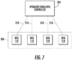
FIG. 7 illustrates a schematic view of one embodiment of an upgraded farm-level controller communicating an upgraded network protocol to a plurality of wind turbine generators in a subset of wind turbines in a wind farm. - Reference now will be made in detail to embodiments of the invention, one or more examples of which are illustrated in the drawings. Each example is provided by way of explanation of the invention, not limitation of the invention. In fact, it will be apparent to those skilled in the art that various modifications and variations can be made in the present invention without departing from the scope or spirit of the invention. For instance, features illustrated or described as part of one embodiment can be used with another embodiment to yield a still further embodiment. Thus, it is intended that the present invention covers such modifications and variations as come within the scope of the appended claims and their equivalents.
- Referring now to the drawings,
FIG. 1 illustrates a schematic diagram of one embodiment of a windturbine power system 100 according to the present disclosure. Example aspects of the present disclosure are discussed with reference to the windturbine power system 100 ofFIG. 1 for purposes of illustration and discussion. Those of ordinary skill in the art, using the disclosures provided herein, should understand that example aspects of the present disclosure are also applicable in other power systems, such as a wind, solar, gas turbine, or other suitable power generation system. - In the illustrated embodiment, the wind
turbine power system 100 includes arotor 102 includes a plurality ofrotor blades 102 coupled to arotatable hub 106, and together define a propeller. The propeller is coupled to anoptional gearbox 108, which is, in turn, coupled to agenerator 110. In accordance with aspects of the present disclosure, thegenerator 110 may be any suitable generator, including, but not limited to a doubly fed induction generator (DFIG) or a fully fed induction generator. Further, thegenerator 110 includes astator 112 and arotor 114. Thestator 112 is typically coupled to astator bus 116 and apower converter 120 via arotor bus 118. Thestator bus 116 provides an output multiphase power (e.g. three-phase power) from thestator 112 and therotor bus 118 provides an output multiphase power (e.g. three-phase power) of therotor 114. - Referring to the
power converter 120, thegenerator 110 is coupled via therotor bus 118 to a rotor-side converter 122. The rotor-side converter 122 is coupled to a line-side converter124 which in turn is coupled to a line-side bus 126. In example configurations, the rotor-side converter 122 and the line-side converter 124 are configured for normal operating mode in a three-phase, pulse width modulation (PWM) arrangement using insulated gate bipolar transistor (IGBT) switching elements. The rotor-side converter 122 and the line-side converter 124 can be coupled via aDC link 128 across which is theDC link capacitor 130. - The wind
turbine power system 100 may also include a turbine-level controller 132 configured to control the operation of the various components of thesystem 100 as well as implementing any method steps as described herein. Thus, thecontroller 132 can include any number of control devices. In one implementation, as shown inFIG. 2 , thecontroller 132 can include one or more processor(s) 134 and associated memory device(s) 136 configured to perform a variety of computer-implemented functions and/or instructions (e.g., performing the methods, steps, calculations and the like and storing relevant data as disclosed herein). The instructions when executed by theprocessor 134 can cause theprocessor 134 to perform operations, including providing control commands to the various system components. Additionally, thecontroller 132 may include acommunications module 138 to facilitate communications between thecontroller 132 and the various components of thepower system 100, e.g. any of the components ofFIG. 1 . Further, thecommunications module 138 may include a sensor interface 140 (e.g., one or more analog-to-digital converters) to permit signals transmitted from one or more sensors to be converted into signals that can be understood and processed by the processors 176. It should be appreciated that the sensors (e.g. sensors 206, 208) may be communicatively coupled to thecommunications module 138 using any suitable means. For example, as shown, thesensors sensor interface 140 via a wired connection. However, in other embodiments, thesensors sensor interface 140 via a wireless connection, such as by using any suitable wireless communications protocol known in the art. As such, theprocessor 134 may be configured to receive one or more signals from the sensors. - As used herein, the term "processor" refers not only to integrated circuits referred to in the art as being included in a computer, but also refers to a controller, a microcontroller, a microcomputer, a programmable logic controller (PLC), an application specific integrated circuit, and other programmable circuits. The
processor 134 is also configured to compute advanced control algorithms and communicate to a variety of Ethernet or serial-based protocols (Modbus, OPC, CAN, etc.). Additionally, the memory device(s) 136 may generally comprise memory element(s) including, but not limited to, computer readable medium (e.g., random access memory (RAM)), computer readable non-volatile medium (e.g., a flash memory), a floppy disk, a compact disc-read only memory (CD-ROM), a magnetooptical disk (MOD), a digital versatile disc (DVD) and/or other suitable memory elements. Such memory device(s) 136 may generally be configured to store suitable computer-readable instructions that, when implemented by the processor(s) 134, configure thecontroller 132 to perform the various functions as described herein. - During operation, alternating current (AC) power generated at the
generator 110 by rotation of therotor 102 is provided via a dual path to anelectrical grid 150. The dual paths are defined by thestator bus 116 and therotor bus 118. On therotor bus side 118, sinusoidal multi-phase (e.g. three-phase) AC power is provided to thepower converter 120. The rotor-side power converter 122 converts the AC power provided from therotor bus 118 into direct current (DC) power and provides the DC power to theDC link 128. Switching elements (e.g. IGBTs) used in bridge circuits of the rotorside power converter 122 can be modulated to convert the AC power provided from therotor bus 118 into DC power suitable for theDC link 128. - The line-
side converter 124 converts the DC power on the DC link 128 into AC output power suitable for theelectrical grid 150. In particular, switching elements (e.g. IGBTs) used in bridge circuits of the line-side power converter 124 can be modulated to convert the DC power on the DC link 128 into AC power on the line-side bus 126. The AC power from thepower converter 120 can be combined with the power from the stator of thegenerator 110 to provide multi-phase power (e.g. three-phase power) having a frequency maintained substantially at the frequency of the electrical grid 150 (e.g. 50 Hz/60 Hz). - Various circuit breakers and switches, such as
breakers power system 100 to connect or disconnect corresponding buses, for example, when current flow is excessive and can damage components of thesystem 100 or for other operational considerations. Additional protection components can also be included in thepower system 100. - As mentioned, a plurality of wind turbines, such as the wind
turbine power system 100 ofFIG. 1 , can be arranged together in a common geographic location and used in conjunction with one another to generate electricity. Such an arrangement is generally referred to as a wind farm. For example, as shown inFIG. 3 , awind farm 200 that is controlled according to the system and method of the present disclosure is illustrated. As shown, thewind farm 200 may include a plurality ofwind turbines 202, including the windturbine power system 100 described above, and a farm-level controller 204. For example, as shown in the illustrated embodiment, thewind farm 200 includes twelve wind turbines, including the windturbine power system 100. However, in other embodiments, thewind farm 200 may include any other number of wind turbines, such as less than twelve wind turbines or greater than twelve wind turbines. In one embodiment, thecontroller 132 of the windturbine power system 100 may be communicatively coupled to the farm-level controller 204 through a wired connection, such as by connecting thecontroller 132 through suitable communicative links 210 (e.g., a suitable cable). Alternatively, thecontroller 132 may be communicatively coupled to the farm-level controller 204 through a wireless connection, such as by using any suitable wireless communications protocol known in the art. In addition, the farm-level controller 204 may be generally configured similar to thecontrollers 132 for each of theindividual wind turbines 202 within thewind farm 200. - In several embodiments, one or more of the
wind turbines 202 in thewind farm 200 may include a plurality of sensors for monitoring various operating data points or control settings of theindividual wind turbines 202 and/or one or more wind parameters of thewind farm 200. For example, as shown, each of thewind turbines 202 includes awind sensor 206, such as an anemometer or any other suitable device, configured for measuring wind speeds or any other wind parameter. In addition, thewind turbine 202 may also include one or moreadditional sensors 208 for measuring additional operating parameters of thewind turbines 202. For instance, thesensors 208 may be configured to monitor the turbine speed and/or electrical properties of thegenerator 110 of eachwind turbine 202. Alternatively, thesensors 208 may include any other sensors that may be utilized to monitor the power output of thewind turbines 202. It should also be understood that thewind turbines 202 in thewind farm 200 may include any other suitable sensor known in the art for measuring and/or monitoring wind parameters and/or wind turbine operating data. - Referring now to
FIG. 4 , a flow diagram of one embodiment of amethod 400 for adapting thewind farm 200 connected to thepower grid 150 to satisfy one or more grid requirements and controlling thewind farm 200 based on the updated system is illustrated. As shown at 402, themethod 400 includes terminating use of an existing farm-level controller 204 of thewind farm 200. For example, as shown inFIG. 5 , the existing farm-level controller 204 of thewind farm 204 is terminated and disconnected from operation. In several embodiments, themethod 400 may also include removing the existing farm-level controller 204 from thewind farm 200. Alternatively, themethod 400 may include leaving the existing farm-level controller 204 in place. - Referring back to
FIG. 4 , as shown at 404, themethod 400 also includes installing an upgraded farm-level controller 304 in place of the existing farm-level controller 204. In addition, as shown at 406, themethod 400 includes communicatively coupling the upgraded farm-level controller 304 to each of the plurality ofwind turbines 202 in thewind farm 200. For example, as shown inFIG. 6 , a schematic diagram of one embodiment of a windfarm management system 300 according to the present disclosure is illustrated. As shown, the existing farm-level controller 204 of thewind farm 204 has been replaced with the upgraded farm-level controller 304. Further, as shown, the upgraded farm-level controller 304 is communicatively coupled to each of the turbine-level controllers 132 of thewind turbines 202 in thewind farm 200 via one or morecommunicative links 210. Alternatively, it should be understood that such communication may also include wireless communication. - As shown at 408 of
FIG. 4 , themethod 400 further includes replacing at least one component of afirst subset 306 of thewind turbines 202 with an upgraded component capable of satisfying one or more grid requirements. More specifically, in one embodiment, thesubset 306 ofwind turbines 202 may include from about 10% to about 50% of the plurality ofwind turbines 202. In further embodiments, thesubset 306 ofwind turbines 202 may include any suitable percentage ofwind turbines 202 in thewind farm 200 that is less than 100% of theturbines 202. - In addition, shown in the illustrated embodiment of
FIG. 6 , the replaced component(s) of thewind turbines 202 may include an upgradedpower converter 320 of each of thewind turbines 202 in thesubset 306. As such, the upgradedpower converters 320 may include new features relative to the features of the existingpower converters 120. Further, in exemplary embodiments, one or more of these features may be a technologically advanced component (relative to the corresponding component of the existing power converter) that facilitates the implementation of newer, more efficient technology. More specifically, in the present disclosure, the upgradedpower converters 320 are capable of staying connected to thepower grid 150 during various adverse grid events. Thus, the upgradedpower converters 320 are required with improved capabilities such as zero voltage ride through, low voltage ride through, and/or high voltage ride through. - Thus, referring still to
FIG. 4 , as shown at 410, themethod 400 includes controlling thewind farm 200 via the upgraded farm-level controller 304. More specifically, in certain embodiments, the upgraded farm-level controller 304 may control thewind farm 200 by controlling thesubset 306 ofwind turbines 202 via the upgradedpower converters 320 and controlling the remaining wind turbines 202 (e.g. with a second subset 308) via existingpower converters 120. - In further embodiments, the upgraded farm-
level controller 304 may also control thesubset 306 ofwind turbines 202 so as to satisfy one or more frequency droop requirements of thepower grid 150. For example, as shown inFIG. 7 , the upgraded farm-level controller 304 may communicate an upgradednetwork protocol 310 with each of thewind turbines 202 in thesubset 306 so as to satisfy one or more frequency droop requirements. More specifically, as shown, the upgradednetwork protocol 310 is configured to drive thegenerators 110 of thesubset 306 ofwind turbines 202 to run in parallel so that loads are shared amount saidgenerators 110 in proportion to their power rating. - This written description uses examples to disclose the invention, including the preferred mode, and also to enable any person skilled in the art to practice the invention, including making and using any devices or systems and performing any incorporated methods. The patentable scope of the invention is defined by the claims, and may include other examples that occur to those skilled in the art. Such other examples are intended to be within the scope of the claims if they include structural elements that do not differ from the literal language of the claims, or if they include equivalent structural elements with insubstantial differences from the literal languages of the claims.
- Various aspects and embodiments of the present invention are defined by the following numbered clauses:
- 1. A method for controlling a wind farm connected to a power grid, the wind farm having a plurality of wind turbines, the method comprising:
- terminating use of an existing farm-level controller of the wind farm;
- installing an upgraded farm-level controller in place of the existing farm-level controller;
- communicatively coupling the upgraded farm-level controller to each of the plurality of wind turbines;
- replacing at least one component of a subset of the wind turbines with an upgraded component capable of satisfying one or more grid requirements; and,
- controlling the wind farm via the upgraded farm-level controller.
- 2. The method of
clause 1, wherein the at least one component comprises an upgraded power converter of each of the wind turbines in the subset. - 3. The method of any preceding clause, wherein controlling the wind farm via the upgraded farm-level controller further comprises controlling the subset of wind turbines via the upgraded power converters and controlling remaining wind turbines via existing power converters.
- 4. The method of any preceding clause, wherein the subset of wind turbines comprises from about 10% to about 50% of the plurality of wind turbines.
- 5. The method of any preceding clause, further comprising controlling the subset of wind turbines so as to satisfy one or more frequency droop requirements of the power grid.
- 6. The method of any preceding clause, wherein controlling the subset of wind turbines so as to satisfy one or more frequency droop requirements of the power grid further comprises communicating, via the upgraded farm-level controller, an upgraded network protocol with each of the wind turbines in the subset.
- 7. The method of any preceding clause, further comprising removing the existing farm-level controller from the wind farm.
- 8. The method of any preceding clause, wherein the one or more grid requirements comprise at least one zero voltage ride through, low voltage ride through, or high voltage ride through.
- 9. A method for adapting a wind farm connected to a power grid to satisfy one or more grid requirements, the wind farm having a plurality of wind turbines, the method comprising:
- terminating use of an existing farm-level management system of the wind farm;
- installing an upgraded farm-level management system in place of the existing farm-level management system capable of satisfying one or more grid requirements;
- communicatively coupling the upgraded farm-level management system to each of the plurality of wind turbines.
- 10. The method of any preceding clause, wherein the upgraded farm-level management system comprises a farm-level controller and a plurality of upgraded power converters.
- 11. The method of any preceding clause, further comprising replacing a subset of existing power converters of the plurality of wind turbines with the plurality of upgraded power converters.
- 12. The method of any preceding clause, wherein the subset of wind turbines comprises from about 10% to about 50% of the plurality of wind turbines.
- 13. The method of any preceding clause, further comprising controlling the subset of wind turbines via the upgraded power converters and controlling remaining wind turbines via existing power converters.
- 14. The method of any preceding clause, further comprising controlling the subset of wind turbines so as to satisfy one or more frequency droop requirements of the power grid.
- 15. The method of any preceding clause, wherein controlling the subset of wind turbines so as to satisfy one or more frequency droop requirements of the power grid further comprises communicating, via the upgraded farm-level controller, an upgraded network protocol with each of the wind turbines in the subset.
- 16. The method of any preceding clause, further comprising removing the existing farm-level controller from the wind farm.
- 17. The method of any preceding clause, wherein the one or more grid requirements comprise at least one zero voltage ride through, low voltage ride through, or high voltage ride through.
- 18. A wind farm management system, comprising:
- a farm-level controller;
- a plurality of wind turbines each comprising a turbine-level controller, the turbine-level controllers communicatively coupled to the farm-level controller,
- wherein a first subset of the wind turbines comprises an upgraded power converter and a second subset of the wind turbines comprises an existing power converter, each of the upgraded power converters capable of satisfying one or more grid requirements.
- 19. The wind farm management system of any preceding clause, wherein the first subset of wind turbines comprises from about 10% to about 50% of the plurality of wind turbines.
- 20. The wind farm management system of any preceding clause, wherein the one or more grid requirements comprise at least one zero voltage ride through, low voltage ride through, or high voltage ride through.
Claims (11)
- A method (400) for controlling a wind farm (200) connected to a power grid (150), the wind farm (200) having a plurality of wind turbines (202), the method (400) comprising:terminating (402) use of an existing farm-level controller (204) of the wind farm (200);installing (404) an upgraded farm-level controller (304) in place of the existing farm-level controller (204);communicatively coupling (406) the upgraded farm-level controller (304) to each of the plurality of wind turbines (202);replacing (408) at least one component of a subset (406) of the wind turbines (202) with an upgraded component capable of satisfying one or more grid (150) requirements; and,controlling (410) the wind farm (200) via the upgraded farm-level controller (304).
- The method (400) of claim 1 wherein the at least one component comprises an upgraded power converter (320) of each of the wind turbines (202) in the subset (406).
- The method (400) of claim 2, wherein controlling the wind farm (200) via the upgraded farm-level controller (304) further comprises controlling the subset (406) of wind turbines (202) via the upgraded power converter (320)s and controlling remaining wind turbines (202) via existing power converters.
- The method (400) of any of the preceding claims, wherein the subset (406) of wind turbines (202) comprises from about 10% to about 50% of the plurality of wind turbines (202).
- The method (400) of any of the preceding claims, further comprising controlling the subset (406) of wind turbines (202) so as to satisfy one or more frequency droop requirements of the power grid (150).
- The method (400) of claim 5, wherein controlling the subset (406) of wind turbines (202) so as to satisfy one or more frequency droop requirements of the power grid (150) further comprises communicating, via the upgraded farm-level controller (304), an upgraded network protocol with each of the wind turbines (202) in the subset (406).
- The method (400) of any of the preceding claims, further comprising removing the existing farm-level controller (204) from the wind farm (200).
- The method (400) of any of the preceding claims, wherein the one or more grid requirements comprise at least one zero voltage ride through, low voltage ride through, or high voltage ride through.
- A wind farm management system (300), comprising:a farm-level controller (304);a plurality of wind turbines (202) each comprising a turbine-level controller (132), the turbine-level controllers (132) communicatively coupled to the farm-level controller (304),wherein a first subset (406) of the wind turbines (202) comprises an upgraded power converter (320) and a second subset (408) of the wind turbines (202) comprises an existing power converter (120), each of the upgraded power converters (320) capable of satisfying one or more grid requirements.
- The wind farm management system (300) of claim 9, wherein the first subset (406) of wind turbines (202) comprises from about 10% to about 50% of the plurality of wind turbines (202).
- The wind farm management system (300) of claim 9 or 10, wherein the one or more grid requirements comprise at least one zero voltage ride through, low voltage ride through, or high voltage ride through.
Applications Claiming Priority (1)
| Application Number | Priority Date | Filing Date | Title |
|---|---|---|---|
| US15/716,638 US20190093632A1 (en) | 2017-09-27 | 2017-09-27 | Methods for adapting wind farms for grid compliance |
Publications (2)
| Publication Number | Publication Date |
|---|---|
| EP3462018A1 true EP3462018A1 (en) | 2019-04-03 |
| EP3462018B1 EP3462018B1 (en) | 2023-06-14 |
Family
ID=63678522
Family Applications (1)
| Application Number | Title | Priority Date | Filing Date |
|---|---|---|---|
| EP18196039.4A Active EP3462018B1 (en) | 2017-09-27 | 2018-09-21 | Methods for adapting wind farms for grid compliance |
Country Status (5)
| Country | Link |
|---|---|
| US (1) | US20190093632A1 (en) |
| EP (1) | EP3462018B1 (en) |
| CN (1) | CN109555646B (en) |
| DK (1) | DK3462018T3 (en) |
| ES (1) | ES2955086T3 (en) |
Families Citing this family (2)
| Publication number | Priority date | Publication date | Assignee | Title |
|---|---|---|---|---|
| US11428209B2 (en) * | 2017-07-14 | 2022-08-30 | General Electric Company | System and method for operating a wind farm for fast connection after farm shutdown |
| CN112881820B (en) * | 2019-11-29 | 2024-05-24 | 西门子歌美飒可再生能源创新与技术有限公司 | Power system and method of performing a test procedure of a power system of a wind turbine |
Citations (3)
| Publication number | Priority date | Publication date | Assignee | Title |
|---|---|---|---|---|
| US20060171086A1 (en) * | 2005-02-01 | 2006-08-03 | Vrb Power Systems Inc. | Method for retrofitting wind turbine farms |
| EP2696070A1 (en) * | 2011-04-01 | 2014-02-12 | Mitsubishi Heavy Industries, Ltd. | Apparatus for controlling wind power generation apparatus, wind power generation apparatus, wind farm, and method for controlling wind power generation apparatus |
| WO2017088879A1 (en) * | 2015-11-26 | 2017-06-01 | Vestas Wind Systems A/S | A method for assessing performance impact of a power upgrade |
Family Cites Families (6)
| Publication number | Priority date | Publication date | Assignee | Title |
|---|---|---|---|---|
| US8046109B2 (en) * | 2009-12-16 | 2011-10-25 | General Electric Company | Method and systems for operating a wind turbine |
| GB2489753A (en) * | 2011-04-08 | 2012-10-10 | Cummins Generator Technologies | Power generation system |
| EP2859638B1 (en) * | 2012-06-12 | 2020-05-06 | Vestas Wind Systems A/S | Wind-power-plant control upon low-voltage grid faults |
| US9450416B2 (en) * | 2013-07-16 | 2016-09-20 | Siemens Aktiengesellschaft | Wind turbine generator controller responsive to grid frequency change |
| EP3077668B1 (en) * | 2013-11-21 | 2020-07-22 | General Electric Company | System and method for assessing the performance impact of wind turbine upgrades |
| US10443571B2 (en) * | 2014-10-16 | 2019-10-15 | Ingeteam Power Technology, S.A. | Kit for a wind station, and method |
-
2017
- 2017-09-27 US US15/716,638 patent/US20190093632A1/en not_active Abandoned
-
2018
- 2018-09-21 DK DK18196039.4T patent/DK3462018T3/en active
- 2018-09-21 EP EP18196039.4A patent/EP3462018B1/en active Active
- 2018-09-21 ES ES18196039T patent/ES2955086T3/en active Active
- 2018-09-27 CN CN201811130768.5A patent/CN109555646B/en active Active
Patent Citations (3)
| Publication number | Priority date | Publication date | Assignee | Title |
|---|---|---|---|---|
| US20060171086A1 (en) * | 2005-02-01 | 2006-08-03 | Vrb Power Systems Inc. | Method for retrofitting wind turbine farms |
| EP2696070A1 (en) * | 2011-04-01 | 2014-02-12 | Mitsubishi Heavy Industries, Ltd. | Apparatus for controlling wind power generation apparatus, wind power generation apparatus, wind farm, and method for controlling wind power generation apparatus |
| WO2017088879A1 (en) * | 2015-11-26 | 2017-06-01 | Vestas Wind Systems A/S | A method for assessing performance impact of a power upgrade |
Non-Patent Citations (2)
| Title |
|---|
| JOHN MCKENNA: "Upgrade old turbines to their full potential", WINDPOWER MONTHLY, 1 December 2012 (2012-12-01), pages 1 - 8, XP055553602, Retrieved from the Internet <URL:https://www.windpowermonthly.com/article/1161695/upgrade-old-turbines-full-potential> [retrieved on 20190207] * |
| KAROUI RIDHA ET AL: "Repowering of the wind farm of Sidi-Daoud Tunisia", 2017 INTERNATIONAL CONFERENCE ON ADVANCED SYSTEMS AND ELECTRIC TECHNOLOGIES (IC_ASET), IEEE, 14 January 2017 (2017-01-14), pages 316 - 322, XP033124584, DOI: 10.1109/ASET.2017.7983712 * |
Also Published As
| Publication number | Publication date |
|---|---|
| CN109555646B (en) | 2022-10-21 |
| ES2955086T3 (en) | 2023-11-28 |
| US20190093632A1 (en) | 2019-03-28 |
| DK3462018T3 (en) | 2023-09-04 |
| EP3462018B1 (en) | 2023-06-14 |
| CN109555646A (en) | 2019-04-02 |
Similar Documents
| Publication | Publication Date | Title |
|---|---|---|
| CN105715452B (en) | System and method for increasing wind turbine power output | |
| US20160065105A1 (en) | System and method for optimizing wind turbine operation | |
| DK177553B1 (en) | Wind Turbine with a Primary and a Secondary Generator and Method of Operating such Wind Turbine | |
| US10340829B2 (en) | Electrical power circuit and method of operating same | |
| US10855079B1 (en) | System and method for reducing oscillations in a renewable energy power system | |
| EP3410555B1 (en) | Electrical power systems having zig-zag transformers | |
| DK201570555A1 (en) | System and method for improving reactive current response time in a wind turbine | |
| US9893563B2 (en) | System and method for operating a wind turbine | |
| EP3745551B1 (en) | System and method for controlling harmonics in a renewable energy power system | |
| EP3462018B1 (en) | Methods for adapting wind farms for grid compliance | |
| EP3651350A1 (en) | System and method for wind power generation and transmission in electrical power systems | |
| EP3819496A1 (en) | System and method for farm-level control of transient power boost during frequency events | |
| US20180342875A1 (en) | Electrical power systems and subsystems | |
| US20200102935A1 (en) | Renewable Energy Source with Energy Storage Device | |
| US11428209B2 (en) | System and method for operating a wind farm for fast connection after farm shutdown | |
| US11879433B2 (en) | Method for operating a wind turbine, and a power plant | |
| EP3457417A1 (en) | Control method for protecting transformers | |
| EP3410556A1 (en) | Control method for protecting generators | |
| US12492682B2 (en) | Heating circuit for a heating system of a wind turbine and methods of operating same | |
| US12129828B2 (en) | Method for operating a wind turbine, and a power plant |
Legal Events
| Date | Code | Title | Description |
|---|---|---|---|
| PUAI | Public reference made under article 153(3) epc to a published international application that has entered the european phase |
Free format text: ORIGINAL CODE: 0009012 |
|
| STAA | Information on the status of an ep patent application or granted ep patent |
Free format text: STATUS: THE APPLICATION HAS BEEN PUBLISHED |
|
| AK | Designated contracting states |
Kind code of ref document: A1 Designated state(s): AL AT BE BG CH CY CZ DE DK EE ES FI FR GB GR HR HU IE IS IT LI LT LU LV MC MK MT NL NO PL PT RO RS SE SI SK SM TR |
|
| AX | Request for extension of the european patent |
Extension state: BA ME |
|
| STAA | Information on the status of an ep patent application or granted ep patent |
Free format text: STATUS: REQUEST FOR EXAMINATION WAS MADE |
|
| 17P | Request for examination filed |
Effective date: 20190927 |
|
| RBV | Designated contracting states (corrected) |
Designated state(s): AL AT BE BG CH CY CZ DE DK EE ES FI FR GB GR HR HU IE IS IT LI LT LU LV MC MK MT NL NO PL PT RO RS SE SI SK SM TR |
|
| STAA | Information on the status of an ep patent application or granted ep patent |
Free format text: STATUS: EXAMINATION IS IN PROGRESS |
|
| 17Q | First examination report despatched |
Effective date: 20210914 |
|
| GRAP | Despatch of communication of intention to grant a patent |
Free format text: ORIGINAL CODE: EPIDOSNIGR1 |
|
| STAA | Information on the status of an ep patent application or granted ep patent |
Free format text: STATUS: GRANT OF PATENT IS INTENDED |
|
| RIC1 | Information provided on ipc code assigned before grant |
Ipc: F03D 7/02 20060101ALN20220927BHEP Ipc: H02J 3/38 20060101ALI20220927BHEP Ipc: F03D 80/50 20160101ALI20220927BHEP Ipc: F03D 9/25 20160101ALI20220927BHEP Ipc: F03D 7/04 20060101AFI20220927BHEP |
|
| INTG | Intention to grant announced |
Effective date: 20221013 |
|
| GRAJ | Information related to disapproval of communication of intention to grant by the applicant or resumption of examination proceedings by the epo deleted |
Free format text: ORIGINAL CODE: EPIDOSDIGR1 |
|
| STAA | Information on the status of an ep patent application or granted ep patent |
Free format text: STATUS: EXAMINATION IS IN PROGRESS |
|
| GRAP | Despatch of communication of intention to grant a patent |
Free format text: ORIGINAL CODE: EPIDOSNIGR1 |
|
| STAA | Information on the status of an ep patent application or granted ep patent |
Free format text: STATUS: GRANT OF PATENT IS INTENDED |
|
| INTC | Intention to grant announced (deleted) | ||
| RIC1 | Information provided on ipc code assigned before grant |
Ipc: F03D 7/02 20060101ALN20230208BHEP Ipc: H02J 3/38 20060101ALI20230208BHEP Ipc: F03D 80/50 20160101ALI20230208BHEP Ipc: F03D 9/25 20160101ALI20230208BHEP Ipc: F03D 7/04 20060101AFI20230208BHEP |
|
| INTG | Intention to grant announced |
Effective date: 20230222 |
|
| GRAS | Grant fee paid |
Free format text: ORIGINAL CODE: EPIDOSNIGR3 |
|
| GRAA | (expected) grant |
Free format text: ORIGINAL CODE: 0009210 |
|
| STAA | Information on the status of an ep patent application or granted ep patent |
Free format text: STATUS: THE PATENT HAS BEEN GRANTED |
|
| AK | Designated contracting states |
Kind code of ref document: B1 Designated state(s): AL AT BE BG CH CY CZ DE DK EE ES FI FR GB GR HR HU IE IS IT LI LT LU LV MC MK MT NL NO PL PT RO RS SE SI SK SM TR |
|
| REG | Reference to a national code |
Ref country code: CH Ref legal event code: EP |
|
| REG | Reference to a national code |
Ref country code: DE Ref legal event code: R096 Ref document number: 602018051775 Country of ref document: DE |
|
| P01 | Opt-out of the competence of the unified patent court (upc) registered |
Effective date: 20230530 |
|
| REG | Reference to a national code |
Ref country code: AT Ref legal event code: REF Ref document number: 1579410 Country of ref document: AT Kind code of ref document: T Effective date: 20230715 |
|
| REG | Reference to a national code |
Ref country code: DK Ref legal event code: T3 Effective date: 20230828 |
|
| REG | Reference to a national code |
Ref country code: LT Ref legal event code: MG9D |
|
| REG | Reference to a national code |
Ref country code: NL Ref legal event code: MP Effective date: 20230614 |
|
| PG25 | Lapsed in a contracting state [announced via postgrant information from national office to epo] |
Ref country code: SE Free format text: LAPSE BECAUSE OF FAILURE TO SUBMIT A TRANSLATION OF THE DESCRIPTION OR TO PAY THE FEE WITHIN THE PRESCRIBED TIME-LIMIT Effective date: 20230614 Ref country code: NO Free format text: LAPSE BECAUSE OF FAILURE TO SUBMIT A TRANSLATION OF THE DESCRIPTION OR TO PAY THE FEE WITHIN THE PRESCRIBED TIME-LIMIT Effective date: 20230914 |
|
| REG | Reference to a national code |
Ref country code: AT Ref legal event code: MK05 Ref document number: 1579410 Country of ref document: AT Kind code of ref document: T Effective date: 20230614 |
|
| REG | Reference to a national code |
Ref country code: ES Ref legal event code: FG2A Ref document number: 2955086 Country of ref document: ES Kind code of ref document: T3 Effective date: 20231128 |
|
| PG25 | Lapsed in a contracting state [announced via postgrant information from national office to epo] |
Ref country code: RS Free format text: LAPSE BECAUSE OF FAILURE TO SUBMIT A TRANSLATION OF THE DESCRIPTION OR TO PAY THE FEE WITHIN THE PRESCRIBED TIME-LIMIT Effective date: 20230614 Ref country code: NL Free format text: LAPSE BECAUSE OF FAILURE TO SUBMIT A TRANSLATION OF THE DESCRIPTION OR TO PAY THE FEE WITHIN THE PRESCRIBED TIME-LIMIT Effective date: 20230614 Ref country code: LV Free format text: LAPSE BECAUSE OF FAILURE TO SUBMIT A TRANSLATION OF THE DESCRIPTION OR TO PAY THE FEE WITHIN THE PRESCRIBED TIME-LIMIT Effective date: 20230614 Ref country code: LT Free format text: LAPSE BECAUSE OF FAILURE TO SUBMIT A TRANSLATION OF THE DESCRIPTION OR TO PAY THE FEE WITHIN THE PRESCRIBED TIME-LIMIT Effective date: 20230614 Ref country code: HR Free format text: LAPSE BECAUSE OF FAILURE TO SUBMIT A TRANSLATION OF THE DESCRIPTION OR TO PAY THE FEE WITHIN THE PRESCRIBED TIME-LIMIT Effective date: 20230614 Ref country code: GR Free format text: LAPSE BECAUSE OF FAILURE TO SUBMIT A TRANSLATION OF THE DESCRIPTION OR TO PAY THE FEE WITHIN THE PRESCRIBED TIME-LIMIT Effective date: 20230915 |
|
| REG | Reference to a national code |
Ref country code: DE Ref legal event code: R081 Ref document number: 602018051775 Country of ref document: DE Owner name: GENERAL ELECTRIC RENOVABLES ESPANA, S.L., ES Free format text: FORMER OWNER: GENERAL ELECTRIC COMPANY, SCHENECTADY, NY, US Ref country code: DE Ref document number: 602018051775 Ref country code: DE Ref legal event code: R082 Ref document number: 602018051775 Country of ref document: DE Representative=s name: ZIMMERMANN & PARTNER PATENTANWAELTE MBB, DE |
|
| RAP2 | Party data changed (patent owner data changed or rights of a patent transferred) |
Owner name: GENERAL ELECTRIC RENOVABLES ESPANA, S.L. |
|
| PG25 | Lapsed in a contracting state [announced via postgrant information from national office to epo] |
Ref country code: FI Free format text: LAPSE BECAUSE OF FAILURE TO SUBMIT A TRANSLATION OF THE DESCRIPTION OR TO PAY THE FEE WITHIN THE PRESCRIBED TIME-LIMIT Effective date: 20230614 |
|
| PG25 | Lapsed in a contracting state [announced via postgrant information from national office to epo] |
Ref country code: SK Free format text: LAPSE BECAUSE OF FAILURE TO SUBMIT A TRANSLATION OF THE DESCRIPTION OR TO PAY THE FEE WITHIN THE PRESCRIBED TIME-LIMIT Effective date: 20230614 |
|
| PG25 | Lapsed in a contracting state [announced via postgrant information from national office to epo] |
Ref country code: IS Free format text: LAPSE BECAUSE OF FAILURE TO SUBMIT A TRANSLATION OF THE DESCRIPTION OR TO PAY THE FEE WITHIN THE PRESCRIBED TIME-LIMIT Effective date: 20231014 |
|
| PG25 | Lapsed in a contracting state [announced via postgrant information from national office to epo] |
Ref country code: SM Free format text: LAPSE BECAUSE OF FAILURE TO SUBMIT A TRANSLATION OF THE DESCRIPTION OR TO PAY THE FEE WITHIN THE PRESCRIBED TIME-LIMIT Effective date: 20230614 Ref country code: SK Free format text: LAPSE BECAUSE OF FAILURE TO SUBMIT A TRANSLATION OF THE DESCRIPTION OR TO PAY THE FEE WITHIN THE PRESCRIBED TIME-LIMIT Effective date: 20230614 Ref country code: RO Free format text: LAPSE BECAUSE OF FAILURE TO SUBMIT A TRANSLATION OF THE DESCRIPTION OR TO PAY THE FEE WITHIN THE PRESCRIBED TIME-LIMIT Effective date: 20230614 Ref country code: PT Free format text: LAPSE BECAUSE OF FAILURE TO SUBMIT A TRANSLATION OF THE DESCRIPTION OR TO PAY THE FEE WITHIN THE PRESCRIBED TIME-LIMIT Effective date: 20231016 Ref country code: IS Free format text: LAPSE BECAUSE OF FAILURE TO SUBMIT A TRANSLATION OF THE DESCRIPTION OR TO PAY THE FEE WITHIN THE PRESCRIBED TIME-LIMIT Effective date: 20231014 Ref country code: EE Free format text: LAPSE BECAUSE OF FAILURE TO SUBMIT A TRANSLATION OF THE DESCRIPTION OR TO PAY THE FEE WITHIN THE PRESCRIBED TIME-LIMIT Effective date: 20230614 Ref country code: CZ Free format text: LAPSE BECAUSE OF FAILURE TO SUBMIT A TRANSLATION OF THE DESCRIPTION OR TO PAY THE FEE WITHIN THE PRESCRIBED TIME-LIMIT Effective date: 20230614 Ref country code: AT Free format text: LAPSE BECAUSE OF FAILURE TO SUBMIT A TRANSLATION OF THE DESCRIPTION OR TO PAY THE FEE WITHIN THE PRESCRIBED TIME-LIMIT Effective date: 20230614 |
|
| PG25 | Lapsed in a contracting state [announced via postgrant information from national office to epo] |
Ref country code: PL Free format text: LAPSE BECAUSE OF FAILURE TO SUBMIT A TRANSLATION OF THE DESCRIPTION OR TO PAY THE FEE WITHIN THE PRESCRIBED TIME-LIMIT Effective date: 20230614 |
|
| REG | Reference to a national code |
Ref country code: DE Ref legal event code: R097 Ref document number: 602018051775 Country of ref document: DE |
|
| REG | Reference to a national code |
Ref country code: DE Ref legal event code: R082 Ref document number: 602018051775 Country of ref document: DE Representative=s name: ZIMMERMANN & PARTNER PATENTANWAELTE MBB, DE |
|
| PLBE | No opposition filed within time limit |
Free format text: ORIGINAL CODE: 0009261 |
|
| STAA | Information on the status of an ep patent application or granted ep patent |
Free format text: STATUS: NO OPPOSITION FILED WITHIN TIME LIMIT |
|
| REG | Reference to a national code |
Ref country code: CH Ref legal event code: PL |
|
| PG25 | Lapsed in a contracting state [announced via postgrant information from national office to epo] |
Ref country code: SI Free format text: LAPSE BECAUSE OF FAILURE TO SUBMIT A TRANSLATION OF THE DESCRIPTION OR TO PAY THE FEE WITHIN THE PRESCRIBED TIME-LIMIT Effective date: 20230614 |
|
| PG25 | Lapsed in a contracting state [announced via postgrant information from national office to epo] |
Ref country code: LU Free format text: LAPSE BECAUSE OF NON-PAYMENT OF DUE FEES Effective date: 20230921 |
|
| 26N | No opposition filed |
Effective date: 20240315 |
|
| REG | Reference to a national code |
Ref country code: BE Ref legal event code: MM Effective date: 20230930 |
|
| GBPC | Gb: european patent ceased through non-payment of renewal fee |
Effective date: 20230921 |
|
| PG25 | Lapsed in a contracting state [announced via postgrant information from national office to epo] |
Ref country code: SI Free format text: LAPSE BECAUSE OF FAILURE TO SUBMIT A TRANSLATION OF THE DESCRIPTION OR TO PAY THE FEE WITHIN THE PRESCRIBED TIME-LIMIT Effective date: 20230614 Ref country code: LU Free format text: LAPSE BECAUSE OF NON-PAYMENT OF DUE FEES Effective date: 20230921 Ref country code: IT Free format text: LAPSE BECAUSE OF FAILURE TO SUBMIT A TRANSLATION OF THE DESCRIPTION OR TO PAY THE FEE WITHIN THE PRESCRIBED TIME-LIMIT Effective date: 20230614 Ref country code: MC Free format text: LAPSE BECAUSE OF FAILURE TO SUBMIT A TRANSLATION OF THE DESCRIPTION OR TO PAY THE FEE WITHIN THE PRESCRIBED TIME-LIMIT Effective date: 20230614 |
|
| REG | Reference to a national code |
Ref country code: IE Ref legal event code: MM4A |
|
| PG25 | Lapsed in a contracting state [announced via postgrant information from national office to epo] |
Ref country code: IE Free format text: LAPSE BECAUSE OF NON-PAYMENT OF DUE FEES Effective date: 20230921 |
|
| PG25 | Lapsed in a contracting state [announced via postgrant information from national office to epo] |
Ref country code: GB Free format text: LAPSE BECAUSE OF NON-PAYMENT OF DUE FEES Effective date: 20230921 |
|
| PG25 | Lapsed in a contracting state [announced via postgrant information from national office to epo] |
Ref country code: CH Free format text: LAPSE BECAUSE OF NON-PAYMENT OF DUE FEES Effective date: 20230930 |
|
| PG25 | Lapsed in a contracting state [announced via postgrant information from national office to epo] |
Ref country code: IE Free format text: LAPSE BECAUSE OF NON-PAYMENT OF DUE FEES Effective date: 20230921 Ref country code: GB Free format text: LAPSE BECAUSE OF NON-PAYMENT OF DUE FEES Effective date: 20230921 Ref country code: FR Free format text: LAPSE BECAUSE OF NON-PAYMENT OF DUE FEES Effective date: 20230930 Ref country code: CH Free format text: LAPSE BECAUSE OF NON-PAYMENT OF DUE FEES Effective date: 20230930 |
|
| REG | Reference to a national code |
Ref country code: ES Ref legal event code: PC2A Owner name: GENERAL ELECTRIC RENOVABLES ESPANA S.L. Effective date: 20240809 |
|
| PG25 | Lapsed in a contracting state [announced via postgrant information from national office to epo] |
Ref country code: BE Free format text: LAPSE BECAUSE OF NON-PAYMENT OF DUE FEES Effective date: 20230930 |
|
| PG25 | Lapsed in a contracting state [announced via postgrant information from national office to epo] |
Ref country code: BG Free format text: LAPSE BECAUSE OF FAILURE TO SUBMIT A TRANSLATION OF THE DESCRIPTION OR TO PAY THE FEE WITHIN THE PRESCRIBED TIME-LIMIT Effective date: 20230614 |
|
| PG25 | Lapsed in a contracting state [announced via postgrant information from national office to epo] |
Ref country code: BG Free format text: LAPSE BECAUSE OF FAILURE TO SUBMIT A TRANSLATION OF THE DESCRIPTION OR TO PAY THE FEE WITHIN THE PRESCRIBED TIME-LIMIT Effective date: 20230614 |
|
| PG25 | Lapsed in a contracting state [announced via postgrant information from national office to epo] |
Ref country code: CY Free format text: LAPSE BECAUSE OF FAILURE TO SUBMIT A TRANSLATION OF THE DESCRIPTION OR TO PAY THE FEE WITHIN THE PRESCRIBED TIME-LIMIT; INVALID AB INITIO Effective date: 20180921 |
|
| PG25 | Lapsed in a contracting state [announced via postgrant information from national office to epo] |
Ref country code: HU Free format text: LAPSE BECAUSE OF FAILURE TO SUBMIT A TRANSLATION OF THE DESCRIPTION OR TO PAY THE FEE WITHIN THE PRESCRIBED TIME-LIMIT; INVALID AB INITIO Effective date: 20180921 |
|
| PGFP | Annual fee paid to national office [announced via postgrant information from national office to epo] |
Ref country code: DE Payment date: 20250820 Year of fee payment: 8 Ref country code: DK Payment date: 20250820 Year of fee payment: 8 |
|
| PG25 | Lapsed in a contracting state [announced via postgrant information from national office to epo] |
Ref country code: TR Free format text: LAPSE BECAUSE OF FAILURE TO SUBMIT A TRANSLATION OF THE DESCRIPTION OR TO PAY THE FEE WITHIN THE PRESCRIBED TIME-LIMIT Effective date: 20230614 |
|
| PGFP | Annual fee paid to national office [announced via postgrant information from national office to epo] |
Ref country code: ES Payment date: 20251001 Year of fee payment: 8 |